1
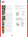
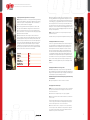
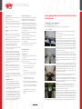
Operator, Safety, And General Maintenance Manual:
• GIO electric bicycles
• Scooter type e-bikes
• 3 wheeler
Operator, safety, and general maintenance manual:
GIO electric bicycles, scooter type e-bikes and 3 wheeler
Please read the following before use:
TABLE OF CONTENTS
Chapter 1: Electric bicycle and its components.
NOTE: Before operating please read this manual carefully to
familiarize yourself with all electric bicycle components
and how they function.
1.
Please observe all local traffic laws. Remember: ignorance of the law is no excuse.
2.
Children of any age, pregnant women, and the elderly should not use an electric bicycle.
3.
For safety, the master power key switch should always be off when pushing bike manually.
4.
Please check both front and rear brakes before operating and adjust if necessary.
5.
Check often for loose fasteners, especially the wheel nuts, handlebars and saddle fasteners.
6.
To prevent controller damage please have power switch on whenever bike is being driven.
7.
Twist the right side handle grip to go, and combine both front and rear brake levers to stop.
8.
For safety when charging please have both the charger and bike in a well ventilated area.
9.
Avoid disassembling entire bike or wiring without proper knowledge.
10. Please be responsible and dispose of all old batteries through a local battery recycler.
Chapter 2: Scooter type e-bikes and 3-wheeled mobility vehicle, components, and technical specs.
Chapter 3: Assembling an electric bicycle.
Chapter 4: Assembling a scooter type e-bike or 3-wheeled mobility vehicle.
Chapter 5: Initial and ongoing adjustments.
Chapter 6: Operating controls/security features of electric bicycles and scooter type e-bikes.
Chapter 7: Charger and correct usage.
Chapter 8: Battery care and instructions for longer battery life.
Chapter 9: Electric motor care and maintenance.
Chapter 10: Electronic speed controller care and attention.
Chapter 11: Stopping in an emergency.
Chapter 12: Electric bicycle circuit diagrams.
Chapter 13: Troubleshooting.
Chapter 14: New technical points.
Chapter 15: Serial number log, and local dealer or service centre location.
11. Please consult your local dealer with any other questions.
Note: Some photos are for general reference, and may differ slightly from your model.
CHAPTERS
Chapter 1: Electric bicycle and its components
Photos and specs of electric bicycles sold in Canada)
Chapter 2: Scooter type e-bikes and 3-wheeled mobility vehicle, components and tech. specs
(Photos of e-bikes)
2
3
Operator, safety, and general maintenance manual:
GIO electric bicycles, scooter type e-bikes and 3 wheeler
Chapter 3: Assembling an electric bicycle
Step 1: Install front wheel by sliding it between the forks assuring that the disk
brake pads are correctly positioned. Then tighten up the 2 wheel nuts according to
spec chart in Chapter 5.10.
Step 2: Install front cargo basket and/or rear luggage rack.
Step 3: Install pedals. They each have a different thread rotation, left and right, so
they will only screw into the correct pedal crank. More on this in Chapter 5, and
make sure they are very tight and torque according to spec chart 5.10.
Chapter 5: Initial and ongoing adjustments
5.1 Adjusting the saddle height: (Applicable to electric bicycle models PB-1, PB-2, PB-3, etc.)
a) The normal height of the saddle should be such that your feet are flat on the ground. (See Figure A)
b) Do not pull the saddle tube out past the safety line. (See Figure B)
c) Some models have an adjustable-suspension-type, saddle mount tube. It has a range variable from 50 to 100 Kg and
is pre-set at 75 Kg. You can adjust it by removing it from the bike and turning the bottom bolt clockwise to increase the
preload, or counter-clockwise to decrease it. kept stored on the bike, or
Step 4: Test drive to make sure that all components are tight and correctly fitted to
the intended rider.
Chapter 4: Assembling a scooter type e-bike or 3-wheeled mobility vehicle
Step1: Install front wheel. First slide the brake shoe assembly into the wheel.
Then slide this assembly between the forks making sure that you position the
brake assembly correctly so that it fits directly into the lug on the left fork tube.
This ensures that the brake hub will not spin when the brakes are applied. Then
slide the axle bolt through the left fork and into the brake hub and right through
the wheel. Now it must go through the spacer (included) that goes on the opposite
(right) side between the wheel and the right fork. Once this is correct, you may
carefully tap the bolt the rest of the way through the fork and attach the nut. Then
tighten it according to the torque specs listed in Chapter 5.10.
Step 2: Install mirrors: Install left and right mirrors making sure they are properly
aligned and tightened with a wrench, while being particularly careful not to scratch
the body work. Then slide the rubber escutcheon (decorative grommet) down to
cover the bolt, and adjust the mirrors so you can see as much as possible behind
you. Then remember to use them constantly.
Step 3: Install rear storage box. Please locate the supplied 4 bolts and 4 nuts, 8
flat washers, 2 flat rubber strips, and 4 round grommets with split ends. The split
grommets go on the mount rack (as pictured) with the flat side up. The two flat
rubber strips go
between the mounting bolts on the flat sections between them on the mount rack.
Set the storage box on top of the rack and slide all 4 bolts through the mounting
holes making sure you use one washer on each. From below, put one washer and
one nut on each bolt and tighten appropriately.
Step 4: Tighten pedals. Most laws currently state that in order to be classified as a
“Power Assisted Bicycle” or “e-bike” and thereby not requiring a driver’s license,
motorcycle plates, or insurance, e-bikes must have pedals. So they should be
assembled and usable at any time. Each one has its own thread (left or right hand
rotation) so they should be assembled according to Chapter 3, Step 3, and always
(depending upon interpretation of the law) either snapped or bolted on to the pedal
shafts
NOTE: Special care should be taken when snapping them onto the pedal shaft to
index the ball snap on the pedal shaft with the corresponding hole in the pedal
crank. The ball snap should also be lubricated.
Step 5: Removing the plastic film. The headlights, turn signals and gauge cluster
may have a thin plastic film to protect them in shipping. It is best to remove this
before it gets exposed to moisture or direct sun. Very carefully and lightly cut
around the outside edge with a small razor then peel the plastic off.
4
5
Operator, safety, and general maintenance manual:
GIO electric bicycles, scooter type e-bikes and 3 wheeler
5.2 Adjusting the brakes: (Applicable to all electric bicycles)
NOTE: Depending on the model of electric bicycle you have and the type of braking
system on it, brake adjustments can be made in a combination of any of 4 different
methods. Refer to Figure C, then adjust both brake cables so that the distance “L”
referred to, is half that when brakes are fully applied.
1) Electric bicycle type models have a basic adjustment at the end of the cable
where it goes into the handlebar lever. Simply loosen the locknut and rotate the
adjuster in or out until you acquire the correct lever specification as pictured in
Figure C, to half distance “L”. Then retighten the locknut, usually finger tight. Major
adjustments are similar to 5.2.2) below.
2) Most 350 watt models have a cable clamp at the end of the cable where it
connects to the brake actuator arm on the brake hub, and this is where you would
make a major adjustment. Being careful not to damage the cable, hold the end of
it with some form of pliers and then loosen the nut on the cable clamp. But please
note that the actuator arm is spring loaded and the cable will slip once loosened,
so you may need an assistant. You will now be able to adjust the cable length
accordingly. Then carefully retighten the cable clamp nut. Several attempts may
be necessary to get it right, but once this is done, the finer adjustments should be
made at the other end of the cable as referred to in 5.2-1) above.
Parts name
Handlebar
Front stem
Saddle
Saddle stern
Front wheel axes
Rear wheel axes
Middle wheel bolt
Moment
18NM
18NM
18NM
18NM
18NM
30NM
30NM
3) Most 500 watt models have an adjuster nut on the threaded end of the cable
where it goes into the brake actuator arm at the brake hub. Tighten or loosen as
necessary. It has detents to make it easy to adjust, and the spring tension will keep
it from rotating loose, so it usually would not require a locknut. 4) Certain models
have three adjustment screws on the outer edge of the rear brake hub. Loosen
the locknuts on all three screws and then use the throttle to slowly spin the wheel
and adjust the screws until the brakes can be heard dragging. Then back them off
slightly so that they are no longer heard dragging and retighten the locknuts. Make
sure they are all evenly balanced.
NOTE: It is normal for the brakes to wear as they are being used, so frequent
adjustments are required.
Remember: How fast you can stop is far more important than how fast you can go!
5.3 Adjusting the handlebar on an electric bicycle:
In order to correctly position the handlebar, loosen the stem bolt enough so that
the stem will be able to rotate and move up or down. Then stand in front of the
handlebar with the front wheel clamped between your legs and adjust it to the
desired height for the intended rider, making sure that the stem is not raised
past the safety line marked upon it. is properly centered (perpendicular to the
wheel when viewed from overhead) and retighten adequately. Now you should
set the handlebar rotational angle by loosening the handlebar clamp bolt, rotate
the handlebars to the desired position and retighten the clamp bolt. Then make
sure the brake levers are all the way out to the grips and at a comfortable angle to
operate, set them according to specifications in Figure C, and tighten securely.
NOTE: These are all extremely important safety items! If in doubt, please consult
your dealer.
5.4 Adjusting the handlebar on a scooter type e-bike
a) Handlebars and grips usually come preset from the factory, but both handle
grips are adjustable axially, so only minor rotational adjustments may be required.
Simply loosen the Phillips or Allen-head cap screws slightly, rotate handle grips to
a comfortable position, retighten, and readjust the mirrors.
NOTE: Both handle grips and mounts should always be tight, and slid all the way
on to the handlebar.
b) For any other adjustments see a dealer or consult service manual.
5.5 Changing front tire and flat repair:
NOTE: Please note the relative orientation of all washers, spacers, or adjustment
plates as you loosen the main axle nuts. Changing the tire or inner tube is the
same for front and rear tires.
a) R & R front wheel according to Chapter 3 or 4, step 1, as applicable.
b) Remove the valve from the valve stem with valve removal tool, to allow all the
air out of the tube.
c) “Break the bead” by pressing the tire away from the rim. Being careful not to
scratch the rim, pry the tire bead over the rim beginning with the side opposite
the valve stem. You may need to use tire lever tools for this task.
d) Pull the inner tube out of the tire, then replace. Tire too, if required, being
careful not to pinch the inner tube and be sure that you install the replacement
tire according to the rotational direction arrow on the sidewall. Reinflate and
maintain at correct pressure as listed on sidewall.
6
7
Operator, safety, and general maintenance manual:
GIO electric bicycles, scooter type e-bikes and 3 wheeler
5.6 Changing rear tire:
5.9 Lubrication of electric bicycles:
NOTE: This procedure is the same as 5.5 above, and also
involves the following steps:
The following items should be cleaned and re-lubricated
with an appropriate lubricant approximately every 6
months: (more often under heavy or bad weather use)
Step 1: Unplug the wiring harness that goes from the
centre of the rear axle to the controller. You may also have
to cut a few zip-ties, and be sure to replace them later.
Step 2: Loosen both chain tensioner nuts slightly and
equally.
Step 3: Remove the safety plate retainer bolts (If
applicable)
a) An appropriate bicycle chain and bearing lubricant
should be used on the upper and lower front fork bearings,
the front and rear axle bearings, the pedals, pedal crank
bearings, pedal crank retainer ball snaps on the pedal
shaft, chain, and the rear chain sprocket ratchet bearing
on the rear wheel hub.
Step 4: Loosen the main axle nuts and remove wheel.
b) An appropriate heavier grease should be used on both
foot peg and all kickstand pivots.
Reverse procedure to re-install, referring to Chapter 5.7
below, and torque to specs in Chapter 5.10.
c) All key locks should be regularly lubricated with an
appropriate lock lubricant as well.
NOTE: Changing the rear tire on a 3-wheeled mobility
vehicle: R&R as required, and follow Chapter 5.5 above.
Make sure you re-torque the lug-nuts evenly.
d) Fork oil service should be done at a dealer or service
centre, only if leaking.
5.7 Adjusting the chain/aligning rear wheel:
a) Loosen the 2 rear axle main nuts 2 or 3 turns (and also
the locknuts if they have them)
b) Both sides should have a chain tension and wheel
alignment adjuster plate with a threaded stud and a
“Nyloc” nut on the end of them. They will go through a
plate located on the very end of the rear suspension fork,
capping it. This adjustment not only tensions the chain
correctly, but it also adjusts the rear wheel tracking,
so both sides must be carefully and equally adjusted to
ensure that the rear wheel is always parallel with the
vehicle center line.
NOTE: This is a very important safety item. If done
incorrectly it would cause the vehicle to track incorrectly,
pull in one direction or the other, and will cause uneven
tire wear. If having difficulty please consult your local
dealer.
c) Once the wheel is correctly aligned, centered, and the
chain is properly tensioned, retighten the main axle nuts
only. The “Nyloc” nuts on the adjuster plate need only to be
snug and equal.
5.8 Adjustable rear shocks:
Some models have adjustable rear coil-over shock
absorbers. If so, they may have up to 5 detents on the
lower coil spring retainer that can be rotated to either
stiffen or soften the suspension. This is to allow for the
most appropriate spring rate, depending on how much
weight the suspension is to support.
To adjust the spring rate preload, simply insert a round
dowel of the correct diameter into the hole on the side
of the lower spring retainer and rotate it to the desired
detent, making sure that both sides are set to the same
setting. This may also be done with large piers, but you
should be careful not to scratch the coil spring retainer as
you rotate it. If in doubt, consult your dealer.
8
e) 3-wheeled mobility vehicle rear axle service should be
done at dealer, or consult service manual.
5.10 Torque specifications:
(Check all data on chart)
5.11 Regular checks:
For maximum safety please check the following items as
often as possible:
All of these apply to electric bicycles, but a) and c) do not
apply to scooter type e-bikes.
a) The centre stem and handlebar clamp bolts.
b) The front and rear main axle shaft nuts.
c) The saddle and saddle stem blots.
d) The brakes.
e) Please check your tire pressure and condition
very often. Look for flats, low pressure, bulges, or
cuts,
and constantly maintain the air pressure as
recommended on the sidewall of the tire.
f) Please check your running lights. High and low
headlights, left and right turn signals (both front and
rear) as well as the rear brake and running light. If
any of these are not working, the most likely cause
is
usually the bulb. If you are unsure how to change
a bulb, please consult your dealer or a service
manual.
Chapter 6: Operating controls/security features of electric bicycles and
scooter type e-bikes
6.1 Operating the main components:
1) Sections a), c), d) and e) apply to electric bicycles.
2) Sections b), c), d), f), g), and h) apply to scooter type e-bikes and 3-wheeled mobility vehicles. For
more on h) refer to Chapter 8.
a) Power key switch: The key lock on the handlebar serves primarily as the
main switch between the b
attery and the controller, and is on when the battery indicator lamps are lit.
Turn off when not in use.
b) Power key and emergency kill switches: Scooter type e-bikes usually have
an master power key switch located below the handlebars on the right side of
the dash console, and an additional emergency kill switch located on the right
handle-grip mount, next to the throttle. Many models also have another main
circuit breaker hidden under the seat. The master power key switch may also
incorporate a steering lock or other tamper resistant features. Some editions
have a small flap that covers the key hole if you flip the tab next to the key hole.
A special lug on the side of the key unlocks this device. Simply insert the lug
into the keyhole and rotate it slightly.
c) Throttle: The throttle is the right handle grip. Rotate the top towards you
to accelerate, and away from you to slow down. It is more efficient if you add
power gradually when accelerating, and coast as far as possible before braking.
NOTE: 3-wheeled mobility vehicles feature a reverse gear switch for backing up
or parking. It is located on the right handle grip mounts next to the emergency
shutoff switch.
d) Brakes and brake cutout switch: The brakes are actuated by squeezing the
levers that are located on both ends of the handlebars, adjacent to the handlegrips. One lever actuates the front and the other actuates the rear. Please take
extra care to balance between the two in slippery or wet conditions. The brake
cutout switch shuts off power to the motor whenever either the front or rear
brakes are applied. 3-wheeled mobility vehicles are equipped with a parking
brake on the right (rear) hand brake.
e) Bell: The bell on an electric bicycle is located on the left handlebar. Simply
push the button to warn others whenever you are approaching.
f) Horn: Scooter type e-bikes usually have horn button near the bottom of the
switches on both the left and right handle grip mounts, and 3-wheeled mobility
vehicles have one on the right only. Both are within easy reach of your thumbs,
and are marked with a horn symbol.
Remember: Electric bicycles are usually very quiet, so it is good to be
courteous at all times, especially when approaching pedestrians or other
cyclists from behind, so please gently alert them with the horn or bell. It is
safer for everyone if they know you are coming.
g) Lights and turn signals: The main headlight switch is located on the right
handle grip. It has 3 positions: Off, running lights only, and all on which includes
the headlights. The headlights also have a high-low beam switch that is located
near the top of the left handle grip mount. The turn signals have a switch that
slides left or right and this is located on the left handle grip mount just under
the headlight high-low switch. Some models have a white button in the centre
of the turn signal switch for cancelling the turn signals. Simply push it to cancel. Models that do not have this would be
9
Operator, safety, and general maintenance manual:
GIO electric bicycles, scooter type e-bikes and 3 wheeler
cancelled manually.
h) Battery level Indicator: The LCD, LED, or analog meter
that indicates the battery power level is located either on
the handlebar or gauge cluster, usually on the right side.
The LCD type models indicate in the form of bars, and 3
bars would indicate a full charge. When the LED lights
are all on in the green, yellow, and red areas it indicates
a full charge, and the analog meter indicates in a similar
way. As the battery power is consumed the LCD bars or
green and yellow lights will systematically start flickering
and will eventually go out, indicating in the red area only,
or showing 1 bar or less. This indicates a low charge level
remaining and that it is time for a recharge. Once the
controller detects that the battery power level is too low,
power to the motor may also be automatically cut off, and
this will occur without warning. The motor may continue to
work intermittently in this mode, but it will eventually stop
completely until the battery is recharged. During this time
it is not recommended to continue to operate the throttle
as equipment damage may occur.
6.2 Operating kickstands and foot pegs:
a) Basic electric bicycles have 1 kickstand, and scooter
type e-bikes usually have 2. A side-stand and a centre
stand. Either one can be used, but extra care should be
taken on soft or uneven ground, or when using the side
stand. It may easily retract in heavy wind or if the vehicle
is bumped and may allow the bike to fall over. The safest
method is to always use the centre stand. It is stronger and
more stable.
b) Foot-pegs: Some models have retractable rear footpegs. They are generally intended for rear passengers
and are designed to fold in for safety if bumped or when
not being used. Simply push the button to deploy, or push
them back in to stow.
6.3 Other noteworthy tips:
a) In rough terrain, during heavy loading, or in the kind
of traffic where you frequently start and stop, the battery
level may lower quickly, but it should increase again as you
continue riding.
b) It is not recommended to use the throttle when the
charging light is lit. Turning the key switch on and off
during this time may damage the battery.
b) Do not lend your electric bicycle to people who are
unfamiliar with them.
c) Please observe all your local traffic laws and other
general social courtesies. Especially when approaching
others from behind.
d) Never ride without proper brakes, and be especially
careful in slippery or wet conditions. Always watch the
road ahead of you, and be ready to brake early, steadily,
and safely to avoid brake lockup. Please use the parking
brake whenever parking a 3-wheeled mobility vehicle.
e) Always wear a well fitted helmet of the correct rating,
and never without the strap properly secured.
f) Leather gloves and high-visibility protective clothing are
always recommended when riding.
g) Whenever passing parked vehicles it is best to allow 4’
in case someone opens a car door.
h) Always turn lights on when riding at night or in low
visibility conditions. Some models work automatically
when necessary.
i) Be extra careful on rough roads as strong vibrations can
damage the tires, wheels, or electronics.
j) Many e-bikes come with a locking rear hub. It may have
a green flap to keep water and dirt out. To lock the rear
wheel hub, simply insert the key and rotate it 360 degrees.
To unlock, reverse this procedure. There are also key locks
for the main power key switch, seat, rear storage box, and
auxiliary wheel lock. It is a good idea to use them.
k) Some electric bicycles have an alarm system. If so, this
will be activated by the master power key switch (check
with dealer) or a key fob remote. Push the locked button
to enable, the unlocked button to disable. It will also chirp
to let you know whenever the main power key switch is
turned on or off.
6.5 Daily maintenance inspection checklist:
a) Wheels, tires, and brakes.b) Key switch and handlegrips. If loose or not working, replace immediately.c) Motor
should be clean and dry. Clean with a damp rag. Avoid
using a power washer or garden hose.
6.6 Riding tips:
c) For maximum mileage range, we suggest operating the
electric bicycle in a low power mode.
a) To protect tires and wheels avoid driving through
obstacles or on rough roads.
d) In combination with the motor, we recommend pedaling
from a standing start and when going uphill.
b) Pedal when climbing for long distances or steep
inclines.
e) When riding downhill you should release the throttle.
6.7 Parking tips:
f) Whenever parking a 3-wheeled mobility vehicle, please
use the parking brake.
a) Park the bicycle smoothly.
6.4 Security and safe operation:
a) Do not ride an electric bicycle without reading this
manual first!
10
b) To avoid inadvertently applying power when parking,
always shut off the emergency kill switch as soon as you
stop to get off the bike, and before you release the brakes
or deploy the kickstand.
c) Try to always use the centre stand.
Both types indicate as follows:
d) Avoid parking the electric bicycle in, or exposing the
battery to the hot sun for long periods of time.
A- Red: The battery needs or is charging
e) To protect the paint, always take care when pulling
into bike stands, or when securing any bicycle locks, and
always avoid parking the electric bicycle in moist or high
temperature conditions.
B- Orange: The battery is partially charged
C-Green: The battery is fully charged and in maintenance
mode
b) Charging the battery off the bike
f) Please use the parking brake when parking a 3-wheeled
mobility vehicle.
Unlock the battery and remove it from the bike. Then
follow instructions 7.2 a), and c).
IMPORTANT NOTE: Always dispose of old batteries
through an approved battery recycler, and keep children
and pets away from batteries. Do not break or burn
the battery. The battery acid or lithium-ion substrates
contained inside are highly corrosive and flammable and
may cause severe injuries or explosion. If this should
occur, rinse with plenty of water and call emergency
services immediately.
NOTE: Lithium-ion bikes have 2 battery packs. So they
would have to be charged in pairs.
Chapter 7: Charger and correct usage
7.1 Charger
Both our lithium-ion and lead-acid-gel batteries as well as
their respective chargers are purpose built for GIO electric
bicycles, and are not interchangeable. Use of any other
chargers may result in serious damage to all components.
The polarity, as well as the input and output voltages of the
charger supplied with your bike at the point of the original
sale is of the correct rating and type, and this information
should be located on a label on the bottom of the charger.
They are CE certified (UL and CSA pending)
7.2 How to use the charger correctly:
NOTE: Unless the riding distance was very short, it is
generally advisable to fully recharge the battery after
each ride. This will insure the longest possible battery
life, because if the battery is left in a low state of charge
for long periods of time the battery life will be diminished.
Please use only the correct charger supplied, and only
according to the following directions.
a) Charging the battery on the bike
After making sure that the master power key switch is off,
connect the output plug from the charger to the charging
receptacle on the bike. Many (but not all) models have
an indicator light on the charger that should turn green
when plugged in to the bike. Then plug the charger into
the correct voltage power outlet and the light should turn
red which would indicate that it is charging. It is normal
for the charger to get warm, and always be sure it is well
ventilated, unobstructed and kept dry at all times. More in
Chapters 7.2 c), and 7.4 a), and b).
NOTE: Certain models have charge-level indicator lights
in addition to the ones on the charger. The GIO electric
bicycle usually has them near the right handle-grip, and
some lithium-ion scooter type e-bikes may also have
another meter in the battery compartment under the seat.
More in Section 10.4 a).
c) Disconnecting the charger
Depending on how discharged the battery is, it may take
several (2-6, but not more than 12) hours to achieve a
full charge. At this point the charging indicator light will
turn green and the charger should be disconnected. First
remove the plug from the local power source and then
disconnect it from the bike.
7.3 Care and attention when charging:
a) When charging a battery separate from the bicycle,
always place the battery on a cool, flat surface. Concrete
floors are not recommended for lengthy periods, and never
place the battery on its side or upside down. Also, never
put anything on top of the charger when charging and keep
it dry at all times.
b) Avoid dropping the battery or charger.
c) Never allow children to insert objects into the charger or
plugs. There are high voltages inside.
d) Please keep charger out of reach of children.
e) Never submerse the charger in liquids, or expose
them directly to rain.7.4 Important notes:a) Use only the
appropriate lead-acid-gel or lithium-ion type battery
charger supplied. Other chargers are likely to cause
significant damage to the equipment or serious injury to
you.
b) When both ends of the charger are plugged in (and
the battery is charging) the indicator light on the charger
will turn red. It is designed to turn green once the battery
is fully charged. If it does not do so after 12 hours, it is
likely some problem has developed. To avoid overcharging
or other damage, immediately unplug the charger and
contact your local dealer.
7.5 BM (Battery management) Charger
The battery management charger has a high-tech CPU
chip which automatically optimizes the battery life. It
constantly monitors and precisely adjusts the battery state
of charge by modulating the voltage.
Chapter 8: Battery care and instructions for longer
battery life
11
Operator, safety, and general maintenance manual:
GIO electric bicycles, scooter type e-bikes and 3 wheeler
8.1 Batteries:
may be required.
NOTE: The electrical power for this bicycle is stored in
either a lead-acid-gel or lithium-ion battery pack. Battery
capacity will always diminish over time, but proper care
and attention to the following will extend the battery life.
a) It is normal for batteries to degrade over time, possibly
in as little as 8 months. If you experience reduced running
distance the batteries may require maintenance or
replacement.
8.2 Care, attention, and correct use of battery:
b) If after 12 hours of charging, the charge indicator light
does not indicate a full charge, both the battery pack and
charger should be checked by a service centre, and are not
recommended to be used until they are.
a) The first 3 times you charge the lithium-ion batteries
you should do so for more than 12 hours.
b) If the daily riding distance is short, it is not mandatory
to charge the battery every time you ride, but it should be
fully charged as often as possible, and never stored in a
low charge state.
c) If the battery is to be unused for a lengthy period of
time, it is advisable to store it only fully-charged (and never
totally discharged) and it should only be in a dry, cool,
ventilated, and shady area in order to maintain the longest
battery life. You should then make sure that it is recharged
at least once a month.
d) Whenever charging an electric bike battery, frequently
verify that the battery pack cover is not getting too hot,
and note the color of the charging indicator light. If the
battery cover does get too hot (getting soft or melting) then
promptly take both the charger and the battery pack to
your local dealer.
NOTE: After several years use the battery capacity will
slowly diminish. It may be possible to recondition the
battery by adding a special liquid and then recharge
it using the battery maintenance charger which will
gradually renew the battery capacity. This service may only
be available through your dealer.
c) The batteries should be charged at least monthly,
especially if they are to be not used for three months or
more. If this is not possible then they should be checked by
an authorized service centre prior to use.
NOTE: Batteries should only be disposed of through a
proper battery recycler.
Chapter 9: Electric motor care and maintenance
9.1 Permanent magnet (brushless) motor:
This electric bicycle features a high torque, high efficiency,
permanent magnet (brushless) motor.
9.2 Motor maintenance:
The motor is maintenance-free, but it is generally
advisable to check all other components for loose or
corroded connections on a regular basis, and it is normal
for the motor to make some noise when activated.
9.3 Important note:
8.3 Important notes:
This bicycle is not designed to be driven in heavy rain or
in water deeper than the height of the motor. This is likely
to cause severe damage to components resulting in costly
repairs or total replacement.
a) Do not use another brand of charger.
9.4 Super power (SP) Geared motor:
b) Do not mount another brand of battery on our electric
bicycle. Different polarity or voltage could damage the
electronic control module (E.C.M.)
Some models may have a variable ratio gear motor which
delivers higher torque under higher loads such as when
going uphill. This converts energy more efficiently by
providing higher power when necessary. 9.5 SP motor
maintenance:
c) Battery capacity diminishes in temperatures below 15
degrees C, and will reduce distance capability by 20%-30%.
d) In low temperature conditions the low voltage protection
system may be more easily activated. To avoid this power
loss you should pedal whenever leaving from a dead stop,
or going uphill.
e) Keep battery away from fire, heat, and other caustic
substances.
Lubrication and maintenance of SP motor should be
carried out in accordance with the service manual.
Chapter 10: Electric speed controller care and attention
10.1 Controller system:
g) Please protect batteries and chargers from shock and
vibration.
The controller system is comprised of a control module,
throttle, and front and rear brake levers. Their functions
are to control the speed of the bicycle by regulating the
power going to the motor, and to protect it against either
too much or too little voltage. On some models this is also
augmented by the EABS (Electrically Assisted Braking
System) which actually recharges the batteries under
braking.
8.4 Battery maintenance
10.2 Protection and use of controller
The following conditions may indicate that battery service
The main electronic control module (E.C.M.) is located
f) Never mix charged and uncharged batteries together
in the battery pack when replacing them. The different
voltages may cause damage to other components.
12
under the battery pack of the electric bicycle, and under
the front of the seat area on the scooter type e-bike. It
handles high current so it does need adequate ventilation.
For maximum efficiency and controller life please make
sure it is not subjected to prolonged periods in direct
sunlight or rain. To reduce excessive power consumption
you should pedal assist whenever going uphill or starting
from a standing stop, and to introduce power gradually
once the bike is in motion.
10.3 Control modes: a), b), and c) apply to electric bicycles,
and a), d), and e) apply to scooter type e-bikes.
a) Throttle only: Simply twist the throttle to drive an
electric bicycle.
b) Pedalec: Some models have a smart sensor located
on the pedal axle which signals the E.C.M. to regulate the
power output going to the motor.
c) Dual Controls: Some models have controls on both
the throttle and the pedals. You may use them in any
combination.
d) Cruise control: Some models are equipped with an
adjustable cruise control feature. This is activated by a red
button on the right handle grip mount that will lock the
speed you set (Once moving) and it will automatically shut
off whenever you hit the brakes, or push the button again.
e) Dual power: Certain models have a green “high and
low range” power button, located on the right handle grip
mount. This will cut the power consumption level in half,
and slightly reduces the maximum speed (From 32 KPH to
24 KPH). High mode (Button out) supplies approximately
10 Amp/Hours to the motor allowing full power and speed.
Low power mode (Button in) limits power consumption to
roughly half (Approx. 5 Amp/Hours) which will enable you
to go considerably farther on a charge, because you will be
able to run at approximately 75% of the speed, while using
only 50% of the power, especially on level ground, and
depending on how you drive.
tNOTE: Refer to photos in Chapter 6.
10.4 Other control functions:
a) The battery level indicator on bicycle type models is
located on the throttle controller, and on scooter type
models this is located on the gauge cluster. The lithiumion models may also have an additional one under the
seat, near the batteries, featuring all red lights, adjacent
to the corresponding colors on a sticker. When the lights
in the green, yellow and red areas are all on, it indicates
a maximum charge. As the power is gradually consumed
they will systematically begin blinking or fading until they
go out completely, leaving only one red light or indicator
on, meaning that it is time to recharge.
b) On models that include an EABS (Electronic Assisted
Braking System) the electro-magnetic field inside the
motor is reversed under braking, and will use this inertia
energy to return power to the battery. But please do not
turn off any power switches when going downhill or this
may destroy the controller.
NOTE: The models with EABS will show a positive charge
on the amp gauge located on the gauge cluster. This will
show you in real time both the power consumed while
running, as well as the power being regenerated while
using the rear brakes, and even a partial application of the
rear brakes will do this.
c) Emergency power off or kill-switch: Most models have a
red main power emergency kill switch. It is usually located
right next to the throttle control on the right handle grip
mount.
NOTE: Refer to photos in Chapter 6.
Chapter 11: Stopping in an emergency
11.1 Brake failure:
Always check front and rear brakes before operating, and
never operate an electric bicycle without doing so first. If
they are not working and you are not able to remedy this
using the information contained in this book, then please
proceed to your local dealer for repairs or adjustments.
Safety is the most important thing, and brake failure is
particularly dangerous on declines or in situations when
something pulls or runs out in front of you. If the brakes do
fail while riding, try to slow down before you hit something,
seek an alternate escape route, and be glad you were
wearing your safety items.
Remember: It isn’t the speed that can hurt, it is the
sudden stop! Always assume that automobiles cannot see
you, and never drive dangerously, without a properly fitted
and secured helmet, under the influence, when over-tired,
in bad weather, or on unsafe road conditions.
11.2 Dealing with momentary power failure:
a) Check the battery terminals and connections for
cleanliness or corrosion.
b) Check the main power plug connections. If loose or
disconnected, please properly reconnect.
c) Check the brake cut-out switch function. If it shorts out
due to rain, dry it with a blow drier, and do not leave an
electric bicycle in the rain for long periods of time.
Chapter 12: Electric bicycle circuit diagram: See charts on
next page
Chapter 14: New technical points
Foot pegs: Push the button in front of the foot peg to
deploy. Push the foot peg toward the rear to retract. Refer
to Chapter 6.2, b).
Kick stands: Refer to Chapter 6.2, a).
Locks: Most e-bikes have an master power key switch (that
may also lock the steering) as well as a seat compartment,
13
Operator, safety, and general maintenance manual:
GIO electric bicycles, scooter type e-bikes and 3 wheeler
trunk, and auxiliary locks. Many feature a rear hub lock. Refer to Chapter 6.1.2, a) and b).
Remote: Some models have an alarm. This is activated or deactivated by a either the master power key switch or a keyfob remote. The vehicle will chirp to remind you. Refer to Chapter 6.4, k).
Electric bicycle
circuit diagrams
Turn signal return: Some models have a white button in the centre of the turn signal switch for cancelling the turn
signals. Others must be cancelled manually. Refer to Chapter 6.2 g).
Adjustable shocks: Refer to Chapter 5.8.
Chapter 15: Serial number log, local dealer and service centre location…
RECORD OF SERIAL NUMBER: __________________________________
LOCAL DEALER INFORMATION:
14
15
Operator, safety, and general maintenance manual:
GIO electric bicycles, scooter type e-bikes and 3 wheeler
Chapter 13:
Troubleshooting
Problem
Condition
Turn vehichle on and
nothing happens. No
any light indications on
the display
A. Check the main
A. Flip dhe breaker
breaker of the handle
lever on “ON”
bar and check if it is on
“ON” position
B. Fasten connections
B. Check power connector
and battery level
Motor dosen’t
rotate but the power
indication light is on
Power indicator light is
on and the breake light
is on
A. Check the battery
and motor connections
16
B. Fastern the motor
connections with the
controller under the seat
A. Loosen the breake,
if there is any corrosion
replace, change a new
one.
B. Battery voltage is
below 42 volts
B. Change or replace the
battery
A. Check the grip for
damage
A. Use the flat head
screwdriver to adjust
the gap between the
rubber handle and the
cover
A. Charger A. Bad connection
light is off between the charger
and the battery
B. Battery
dosen’t
hold the
charger
A. Clearn and fasten
battery terminal
connectors
A. Check the breake
levels if they return to
normal position
The throttle does not
work or switch on, the B. Check the throttle
vehichle moves without spring
acceleration
C. Check the throttle
spring
The range
is low
Solution
B. Check throttle
connections
A. Check the charger
plusg position
B. Charger dosen’t
charge
B. Replace the charger
A. Connections
between the battery
are not good
A. Check all
connections between
the batteries.
B. Replace the bad
battery cell
B. Bad battery cell
17
Operator, safety, and general maintenance manual:
GIO electric bicycles, scooter type e-bikes and 3 wheeler
Authors rights and copyright info;
This electric bicycle and e-bike operator, safety, and general maintenance manual was written by and remains the
intellectual property of Danny A. Halmo, Langley, British Columbia. It is licensed indefinitely to GIO Bikes of Canada for
distribution
through them in continental North America and Hawaii only, as understood between us. Therefore, any printed or
transmitted reproduction of any kind, in whole or in part, anywhere in the world, and in any other language, without the
author’s written consent and paid or payable fee agreement, is a violation of internationalcopyright law, and thereby
enforceable, subject and punishable to the fullest extent thereof. It may be available legally online through the author
or assigned agent www.giobikes.com, and may be licensable to others at a reasonable fee. Please respect the authors
rights.
Furthermore: Whenever and wherever this manual or any part of it thereof is sold separately in printed form, a
10% royalty of the retail sale price is immediately payable to the author from the source vendor or printer. If any of
the aforementioned or any part of it thereof is sold online or as a download, a 50% royalty of the retail sale price is
immediately payable to the author from the source vendor or distributor.
18
19