1
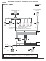
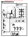
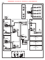
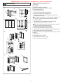
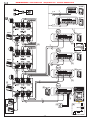
DISTRIBUTED BY: www.leedan.com [email protected] Toll-Free: 800-231-1414
0706 A
GH SERIES
Apartment Intercom System
QuikStart Installation Guide
ATTENTION:
This is an abbreviated Installation Manual, addressing Wiring and Programming of the GH System
only. The complete GH System Installation and Operation Manual is located on the CD that comes
with the GH-BC Bus Control Unit. Access the PDF file from the CD and print the entire manual if a
hard copy is needed. If installing a digital entry system, the program for loading names and numbers
for each tenant is also located on the CD.
ABBREVIATED INSTALLATION & OPERATION MANUAL
-1-
DISTRIBUTED BY: www.leedan.com [email protected] Toll-Free: 800-231-1414
Cabling
1P(Audio)
1P(Video)
1P
Standard system
Capacity
5 Entrance stations
2 Security guard stations
48 Residential stations
Monitor to monitor cabling
Trunk line No.2
Divided cabling with GH-4Z
1Px2
Trunk line No.1
1Px2
Doorbell
GH-4Z 1Px2
1Px2
GH-1KD
1Px2
1Px2
1Px2
1Px2
1Px2
1P
1P
1Px2
GH-4Z
Doorbell
Doorbell
Doorbell
Doorbell
GH-1KD
GH-1KD
GH-1KD
GH-1MD
GH-1MD, unlike GH-1KD,
is only available to connect
on a trunk line
with GH-4Z used
1Px2
GH-1AD
GH-1AD
GH-1KD
Max. 4 apartment stations can be linked per Residence
(including max. 2 monitor stations)
1Px2
On the same trunk line, do not have two wiring methods mixed,
Monitor to monitor & Divided cabling with GH-4Z
1Px2
Trunk line
No. 3 to 6
1Px2
Distribution
point
R1
PS24
R2
PS24
GH-BC
GH-VBC
1Px2
Light control
Timer
Entrance
No. 2 to 5
GH-RY
1Px2
1P
1P
AC
1P
Light
Doorbell
PS24
PS24
Door release
GH-MK
Entrance station
Security guard station
Cable: 1P x 2, 2-conductor cable solid copper & non-braided, polyethylene insulation
Use Aiphone Wire #872002 for Audio, Aiphone Wire #871802 for Video.
-2-
DISTRIBUTED BY: www.leedan.com [email protected] Toll-Free: 800-231-1414
Wiring
Monitor to monitor cabling
Divided cabling with GH-4Z
Trunk line No.2
Trunk line No.1
GH-4Z
A
B
R1 R2 B1 B2
GH-1KD
OUT
B1
B2
R1 R2 B1 B2
LINE OUT
B1
B2
OUT 3
OUT 4
R1
R2
1Px2
B1
IN
B2
OUT
IN
R1
R2
R1
R2
C
CE
A
B
Terminate
the last GH-4Z
1Px2
B1
B2
R1
R2
A
B
IN
1Px2
B1
B2
B1
B2
OUT 1
R1
R2
B1
B2
OUT 2
R1
R2
LINE IN
R1 R2 B1 B2
R1
R2
C
CE
GH-1MD
Doorbell
1Px2
R1
OUT
R2
R1
OUT
R2
R1
IN
R2
C
CE
R1
IN
R2
C
CE
GH-1AD
GH-1AD
Doorbell
R1
OUT
R2
R1
IN
R2
C
CE
A
B1
OUT
B2
R1
IN
R2
C
CE
R1
IN
R2
C
CE
A
Door
bell
B
IN2
IN3
IN4
+
-
+
-
AC
Power supply
IN5
A1 A2 A1 A2 A1 A2 A1 A2 A1 A2
EXP
STD
Video Entrance station No. 2 to 5
Light control
Timer Orange
Blue
1Px2
GH-MK
1P
Orange GH-RYWhite
Light
GH-DA
Doorbell
CN2
R1 R2 ELB ELC ELM RY RY
CN1
A1 A2
CN3
+
GH-VA
GH-NS
CN1
+
CN3
-
AC
+
-
AC
GH-10K CN100
-
2nd
GH-MK
R1
R2
R1
R2
R1
R2
C
CE
+
-
R1
R2
C
CE
+
-
Power supply
Power supply
SW4
Entrance station
-3-
A
B
GH-1KD
OUT1 OUT2 OUT3 OUT4 OUT5 OUT6
IN1
B1
OUT
B2
R1
OUT
R2
B1 B2 B1 B2 B1 B2 B1 B2 B1 B2 B1 B2
AC
B
R1
OUT
R2
1Px2
+
-
A
GH-1KD
B1
IN
B2
GH-BC
+
-
R1
IN
R2
C
CE
B1
IN
B2
Trunk line
No. 3 to 6
Distribution
point
1Px2
GH-1KD
1Px2
Power supply
Door
bell
B
GH-1KD
R1
R2
R1
OUT
R2
B1
IN
B2
1Px2
IN
B1
IN
B2
B1
OUT
B2
1Px2
GH-4Z
Doorbell
B1
OUT
B2
SW4
DISTRIBUTED BY: www.leedan.com [email protected] Toll-Free: 800-231-1414
1
1-1
SYSTEM CONFIGURATIONS
a
e
c
d
Max. 48
Max. 25 / Trunk
(1)
(2)
(3)
[9]
GH-1KD
b
GH-VA + GH-DA +
GH-NS, GH-10K
[1]
GH-VBC
[6]
GH-VA
[5]
[7]
PS
GH-DA
GH-VA + GH-DA +
GH-SW
[10]
GH-1KD
[10]
GH-1KD
[10]
GH-1KD
[9]
GH-1KD
[10]
[5]
[8]
GH-4Z
Max. 6
[10]
GH-1KD
PS
Max. 5
(3 per trunk)
[10]
GH-1KD
PS
GH-BC
GH-4Z
Max. 6
GH-1KD
[10]
2
[5]
[10]
GH-1KD
#6 ~ #2
[10]
a
Max. 48
Max. 25 / Trunk
[10]
GH-1KD
Trunk
:A
:V
:P
c (d)
b
Trunk
#1
1
[10]
GH-1KD
2
1
DP
[2]
[11] GH-1AD
[12] GH-1MD
1
[13] GH-1KD + GH-HS
2
2
1
1
GH-DA +
GH-NS, GH-10K
[3]
SW
[5]
PS
GH-VBC
GH-DA + GH-SW
[4]
GH-VBC
GH-VBC
GH-VBC
GH-VA
GH-1KD / GH-4Z
PS
150 m
STD
e
EXP
SW
PS
150 m
STD
EXP
SW
1
2
A
B
D
G
5
I
J
K
L
3
PQ
8
T
V
O
9Z
WX
U
F
6
N
M
R
C
E
4
H
7S
Y
0
PS
PS-2410LC PS-2410LD
AC
AC
PS-2410DIN
[5]
AC
PS
Max. 2
-4-
STD
SW
GH-MK
[14]
PS
150 m
EXP
DISTRIBUTED BY: www.leedan.com [email protected] Toll-Free: 800-231-1414
1-1
Standard System Configuration Diagram
(1) Audio signal line
(2) Video signal line
(3) Power supply line
a. Entrance station (For details, see 2-1 and 2-2)
[1] Video/audio + digital name scrolling type
GH-VA + GH-DA + GH-NS, GH-10K
[2] Video/audio + direct selection type
GH-VA + GH-DA + GH-SW
[3] Audio + digital name scrolling type
GH-DA + GH-NS, GH-10K
[4] Audio + direct selection type
GH-DA + GH-SW
b. Bus control units
[5] Power supply adapter PS-2410LC, PS-2410LD, PS-2410DIN
[6] Video bus control unit GH-VBC
GH-VBC can be used as an extension adapter as well. To do so,
set the setting switch to "EXP." (2 units per trunk line)
[7] Bus control unit GH-BC
[8] Distribution terminal (junction): sold separately, not available from Aiphone.
c. Residential station (For details, see 2-4): Station-to-station wiring.
d. Residential station (For details, see 2-4): Homerun wiring
Do not mix station-to-station wiring and homerun wiring.
[9] 4-way video junction unit GH-4Z
[10] Color video residential station GH-1KD
[11] Audio residential station GH-1AD
[12] Black &White video residential station GH-1MD
[13] Color video residential station +handset (option) GH-1KD + GH-HS
e. Security Guard Station
[14] Security guard station GH-MK
Entrance Station
Residential Station
Security Guard Station
Residential stations
in the same residence
4-way video junction unit
Capacity
Maximum 5 stations
(up to 3 stations per trunk)
Maximum 48 stations
(up to 25 stations per trunk)
Maximum 2 stations
Maximum 4 stations
(up to 2 monitor stations)
Maximum 6 units per trunk
-5-
DISTRIBUTED BY: www.leedan.com [email protected] Toll-Free: 800-231-1414
1-2
1
2
#1
a
e
f
#2
#1
b
c (d)
#2
b
c (d)
#3
b
c (d)
#4
b
c (d)
a
(1)
(2)
(3)
e
:A
:V
:P
#1
#1
a
f
[1] GH-VBX
#2
GH-VA + GH-DA +
GH-NS, GH-10K
#3
#4
[4]
PS
GH-VA
GH-DA
Max. 8
(3 per trunk)
e GH-MK
1
2
A
B
C
D
G
5
I
J
K
L
M
PQ
T
WX
PS
Y
Max. 2
PS
[4]
c (d)
[2] GH-BCX
[4]
PS
a
GH-VA + GH-DA +
GH-NS, GH-10K
#2
[3] DP
[4]
PS
#2
GH-VA
GH-DA
#4
GH-BC
e GH-MK
1
2
A
B
C
D
G
5
I
J
K
L
M
PQ
T
Y
Max. 2
#4
[3] DP
O
9Z
WX
V
F
6
N
8
U
[4]
PS
3
E
4
H
0
#3
#3
Max. 8
(3 per trunk)
R
Max. 125
Max. 25 / Trunk
GH-1KD / GH-4Z
[4]
#2
7S
[4]
[3] DP
F
O
9Z
V
PS
[3] DP
6
N
8
U
0
[4]
PS
3
E
4
H
R
GH-VBC
GH-BC
GH-BC
7S
b
PS
[4]
PS
PS-2410LC PS-2410LD
AC
AC
PS-2410DIN
AC
-6-
DISTRIBUTED BY: www.leedan.com [email protected] Toll-Free: 800-231-1414
1-2
1-3
Expanded System Configuration Diagram
1. Common trunk line #1, 2
2. Sub trunk line #1 - 4
Sub trunk line #2 - #4 are the same as #1. Maximum 125 units
per sub trunk line.
(1) Audio signal line
(2) Video signal line
(3) Power supply line
a. Entrance station (For details, see 2-1 and 2-2)
b. Bus control unit
c. Residential station (For details, see 2-4):
Station-to-station wiring (For details, see 3-2)
d. Residential station (For details, see 2-4):
Homerun wiring (For details, see 3-3)
Do not mix station-to-station wiring and homerun wiring.
e. Security Guard Station
f. Expanded bus control unit
[1] Expanded video bus control unit GH-VBX
[2] Expanded bus control unit GH-BCX
[3] Distribution terminal (junction): sold separately
[4] Power supply adapter PS-2410LC, PS-2410LD, PS-2410DIN
Wiring Distance
DP = Distribution Point
Entrance Station
Residential stations
per sub trunk line
Residential Station
Security Guard Station
Residential stations
in the same residence
Diameter of wires
GH-BC - DP
DP - GH-DA
GH-VBC - GH-VA
GH-MK - DP
DP - farthest residential station
(R1-R2)
(Includes system with GH-4Z)
GH-VBC - farthest residential station
(1 monitor units/residence)
(Includes system with GH-4Z)
GH-VBC - farthest residential station
(2 monitor units/residence)
(Includes system with GH-4Z)
GH-VBC (SW: STD)
- GH-VBC (SW: EXP)
GH-BC - power supply
Capacity
Maximum 16 stations
(up to 3 stations per trunk)
Maximum 125 stations
(up to 25 stations per trunk)
Maximum 500 stations
Maximum 4 stations
Maximum 4 stations
(up to 2 monitor stations)
100 m
(330')
150 m
(500')
-
50 m
(165')
100 m
(330')
150 m
(500')
100 m
(330')
-
150 m
(500')
5m
(16')
5m
(16')
300 m
(980')
300 m
(980')
2500 m
(8200')
-
GH-VBC - power supply
-
GH-NS - power supply
-
GH-MK - power supply
-
Common trunk line
(Maximum 2 trunk lines)
total wiring length per trunk line
Sub trunk line
(Maximum 4 trunk lines)
total wiring length per trunk line
GH-BC - GH-BCX
-
GH-VBC -GH-VBX
-
GH-DA - GH-BCX
-
GH-VA - GH-VBX
150 m
(500')
-
GH-BCX - farthest residential station
(R1-R2)
(Includes system with GH-4Z)
GH-VBX - farthest residential station
(1 monitor units/residence)
(Includes system with GH-4Z)
GH-VBX - farthest residential station
(2 monitor units/residence)
(Includes system with GH-4Z)
-7-
0.65 mm 0.8 mm 1.0 mm
(22 AWG) (20 AWG) (18 AWG)
5m
(16')
300 m
(980')
300 m
150 m
(980')
(490')
300 m
(980')
300 m
(980')
5m
(16')
5m
(16')
300 m
(980')
300 m
(980')
-
-
2500 m
(8200')
-
-
5m
(16')
150 m
(500')
300 m
(980')
300 m
(980')
300 m
(980')
-
100 m
(330')
150 m
(500')
-
50 m
(165')
100 m
(330')
150 m
(500')
-
DISTRIBUTED BY: www.leedan.com [email protected] Toll-Free: 800-231-1414
2
2-1
1
[1]
[2]
200mm
(7-7/8")
[1]
25mm
(1")
[2]
[3]
Mounting the Entrance Station (1)
[1] Back box
[2] Joint pipe
[3] Back box assembly dimensions
[4] Special screwdriver (enclosed with GH-BC)
1. Mounting the back box
• Make a hole for the cable.
• Use the joint pipe to assemble the back box.
• Make sure the back box is mounted level.
• Mount the camera and GH-NS module at eye-level for the
average height of an adult.
Do not mount the back box on a surface that is recessed by 15
mm (1/2") or more from the external surface of the wall.
2. Set up the modules.
• For information on what modules can be used, see full
Installation Manual provided on CD, pg. 10
6 GH-SW modules can be used. If you would like to connect 7
modules or more, please contact Aiphone.
3. Mount each module panel to the front frame.
• Mount the panels from behind the front frame.
• Insert the notch into the slots on both sides and slide it downward.
4. Mount each module to the mounting bracket.
• Set the modules in the mounting bracket until they click in place.
5. Options
a. Rain hood GF-H
b. Surface-mount box GF-202B
c. Hooded surface-mount box GF-HB
d. 80 cm (32") connection cable GF-C
MOUNTING
W
[1]
GF-2B/3B W (mm)
x1
110
x2
245
x3
380
x4
515
x5
650
x6
785
x7
920
x8
1055
x9
1190
44mm
(1-3/4")
15mm
(1/2")
W (inch)
4-5/16"
4-5/8"
15"
20-1/4"
25-9/16"
30-7/8"
36-1/4"
41-9/16"
46-1/8"
295mm
(11-5/8")
25mm
(1")
25mm
(1")
44mm
(1-3/4")
15mm
(1/2")
W
2
[4]
4
3
5
b
a
c
d
-8-
DISTRIBUTED BY: www.leedan.com [email protected] Toll-Free: 800-231-1414
2-2
2-3
1
1
GH-DA
GH-DA
CN3
GH-NS
CN1
CN2
GH-VA
CN3
CN1
ON
CN1
1
2
3
GH-DA
4
CN2
CN1
103
CN100
CN2
GH-AD
2
GH-10K
3
GF-C
2
ON
1
2
3
4
GH-VA
GH-NS
GH-DA
GH-10K
GH-AD
GF-BP
GF-3B
GF-3B
1 03
GH-DA
GH-DA
ON
1
2
3
4
ON
CN2
10 3
GF-3B
GH-SW
ON
1
GF-3B
GF-3B
GF-C
2
ON
CN1
3
CN2
Mounting the Entrance Station (3)
1. Example of interconnection of modules.
2. Use GF-C to connect to the name scrolling module.
3. To position the speech module in the center row, run GF-C
through the joint pipe in advance.
CN1
CN1
CN2
CN2
CN1
CN1
CN2
CN2
CN1
4
5
GH-DA
CN1
ON
1
2
3
4
CN2
103
Mounting the Entrance Station (2)
1. Remove the terminal cover.
2. From the speech module to the next module, insert the attached
connector into the socket. Make sure to run the cable under the
terminal cover for protection.
3. Plug in the ribbon cables between modules in a daisy-chained manner.
4. Run the connection cable through the joint pipe (which you
should have made open in advance) and connect CN1 of GH-SW
to the next row.
5. Put back the terminal cover.
-9-
DISTRIBUTED BY: www.leedan.com [email protected] Toll-Free: 800-231-1414
2-4
2-5
[3]
GH-1AD
GH-1KD
[1]
1
[2]
[2]
[1]
[3]
83.5mm (3-5/16")
OR
60mm (2-3/8")
[3]
2
SW1 A
B Do not remove the wires (For end users)
IN
OUT
0.65 10 9
R1 R2 R1 R2 C CE
K KE
[4]
SW1 A
d users)
es (For en
e the wir 10 9
not remov OUT 0.65 K KE
B Do IN
CE
1 R2 C
R
R1 R2
Optional Handset
[1] Chassis
[2] Handset (GH-HS)
[3] Screws (x2)
• Connect the station unit joint connector.
GH-HS can be installed only for the color monitor residential
station (GH-1KD).
3
GH-1MD
Residential Station
[1] Mounting screws (x2)
[2] Mounting bracket
[3] 1-gang box or round back box
[4] Terminal block (GH-1AD, GH-1KD)
1. Mount the mounting bracket on the 1-gang box.
2. Connect the wiring to the terminal block.
3. Mount the station unit to the mounting bracket.
Strip away the jacket of the cable and insert all wires into the
slots in an orderly fashion. Failure to do so could result in
pinching that may damage the wiring.
NOTES: To remove the terminal block, slide the terminal block
and pull it out. (GH-1AD, GH-1KD)
- 10 -
DISTRIBUTED BY: www.leedan.com [email protected] Toll-Free: 800-231-1414
3
3-1
WIRING
a
c (d)
b
e
[9]
PS-2410LC PS-2410LD
AC
PS-2410DIN
AC
PS
AC
a
GH-NS #1
NP
1P
1P
A1 A2 A1 A2 A1 A2 A1 A2 A1 A2
b
GH-VA #1
1P
1P
NP
NP
1P
NP
NP
PS
GH-VA
#2 - #5
GH-NS
#2 - #5
SW2
[1]
STD
EXP
A1 A2 A1 A2 A1 A2 A1 A2 A1 A2
IN1 IN2 IN3 IN4 IN5
GH-VBC
[10]
GH-VBC
OUT1 OUT2 OUT3 OUT4 OUT5 OUT6
+ –
+ –
[4]
1P
1P
NP
GH-DA #1
NP
B1 B2 B1 B2 B1 B2 B1 B2 B1 B2 B1 B2
NP
–
1P
+
NP
GH-10K #1
PS
1P
CN1
NP
CN3
A1 A2
CN3
1P
A1A2
NP
+ –
1P
9mm
B1 B2 B1 B2 B1 B2 B1 B2 B1 B2 B1 B2
c (d)
GH-RY
AC
CN1
1
CN100
CN2
A1 A2 A1 A2 A1 A2 A1 A2 A1 A2
R1R2 ELB ELCELMRYRY
ON
CN1
2
3
4
SW2
SW2
VR1
EXP
STD
A1 A2 A1 A2 A1 A2 A1 A2 A1 A2
IN1 IN2 IN3 IN4 IN5
PS
DP
1P
NP
GH-DA
#2 - #5
1P
NP
4 3
2
1
R1
B1 B2 B1 B2 B1 B2 B1 B2 B1 B2 B1 B2
1P
NP
e
R1 R2 R1 R2 C CE +
1P
NP
[6]
1
2
A
B
D
G
5
I
J
K
M
PQ
T
V
[12]
F
O
9Z
WX
U
c (d)
[8]
6
L
N
8
R
-
3
C
E
4
H
7S
Y
0
SW1 #1
ON
1 2 3 4
GH-BC
PS
GH-MK #1
[7]
–
R2
1P
NP
GH-MK
#2
+
NP
1 2 3 4
1P
1 2 3 4
AC
NP
1 2 3 4
PT
PT
[13]
1P
ON
B1 B2 B1 B2 B1 B2 B1 B2 B1 B2 B1 B2
NP
#5
ON
OUT1 OUT2 OUT3 OUT4 OUT5 OUT6
+ –
1P
#4
ON
AC/DC
24V
NP
#3
1P
NP
GH-VBC
1P
1 2 3 4
GH-VBC
NP
M
103
[11]
[5]
ON
1 2 3 4
20
0.5
#2
1P
SW2 #1
ON
[3]
NP
VR1
1P
[2]
GH-BC
#2
ON
1 2 3 4
+ -
PS
1P
NP
- 11 -
R1R2
DISTRIBUTED BY: www.leedan.com [email protected] Toll-Free: 800-231-1414
3-2
3-1
a
b
e
Standard System (1)
[1] Entrance Station
[2] Door release timer (set to "M" at time of shipment)
• Set the duration for the door release function when the door
release button is pressed.
[0.5] - [20]: 0.5 secs - 20 secs
[20] - [M]: Activates while the button is pressed.
[3] Setting switch (GH-DA)
• SW2: 1: Setting switch for camera entrance station monitoring
function (set to OFF at time of shipment)
ON (Up): Monitored.
OFF (Down): Skipped at time of entrance station monitoring.
• SW2: 2 - 4: Entrance station number setting switch (set to #1 at
time of shipment)
[4] External relay GH-RY
For details, see full Installation Manual provided on CD, pg. 23.
[5] Door release relay contact
Less than AC/DC 24 V, 4 A (resistance load)
[6] Security guard station GH-MK
[7] Setting switch (GH-MK)
• SW1: 1: Password reset switch
Set the password reset switch to ON for 2 seconds or more
during standby will reset the password (set to " 1111" at time
of shipment).
• SW1: 2, 3: Unused switch
• SW1: 4: Security guard station number setting switch (set to #1
at time of shipment)
[8] Doorbell button
[9] Power supply adapter PS-2410LC, PS-2410LD, PS-2410DIN
[10] Video bus control unit GH-VBC (SW: STD)
[11] Video bus control unit GH-VBC (SW: EXP)
• To use GH-VBC as an extension adapter, set the setting switch
to "EXP."
[12] Bus control unit GH-BC
[13] Distribution terminal (junction): sold separately
c
1P
NP
GH-1AD
IN OUT
R1R2 R1R2 C CE K KE
1P
NP
R1, R2
SW1
A
c
B
GH-1KD
IN OUT
B1B2 B1B2
1P
NP
IN OUT
R1R2 R1R2 C CE K KE
1P
NP
[2]
K KE
SW1
B
A
GH-1KD
IN OUT
B1B2 B1B2
IN OUT
R1R2R1R2 C CE K KE
[2]
[1]
SW1
GH-1KD
A
B
1P
NP
NP: Non-polarized
1P
NP
SW1 A
B Do not remove the wires (For end users)
IN
OUT
0.65 10 9
R1 R2 R1 R2 C CE
IN OUT
B1B2 B1B2
3-2
K KE
IN OUT
R1R2R1R2 C CE K KE
Standard System (2) Station-to-Station Wiring
[1] Residential station GH-1KD, GH-1AD
• There can be a maximum of 25 stations per system.
• For the terminating residential station, set the setting switch to "A".
[2] Short lead
• To use the emergency alarm switch (see full Installation Manual
provided on CD, pg. 41),
disconnect the short lead and connect the switch.
[3] External relay GH-RY
For details, see full Installation Manual provided on CD, pg. 23.
[4] Doorbell button
1. Do not mix station-to-station wiring with homerun wiring.
2. Station-to-station wiring is not possible for GH-1MD.
GH-VBC
[2]
b
1P
NP
[3]
GH-BC
GH-RY
1P
NP
[4]
B
AC
NP: Non-polarized
- 12 -
3-3
DISTRIBUTED BY: www.leedan.com [email protected] Toll-Free: 800-231-1414
GH-1MD
a
b
e
d
d
1P
NP
B1, B2
B1 B2 R1 R2 C CE K KE
Do not remove the wires!
GH-4Z
1P
NP
R1, R2
GH-1AD
A
IN OUT
R1R2 R1R2 C CE K KE
B
SW1
R1, R2
B1 B2 R1 R2
B1 B2 R1 R2
GH-4Z
B1 B2 R1 R2
1P
NP
SW1
A
B
GH-4Z
[2] GH-1KD
IN OUT
B1B2 B1B2
B1 B2 R1 R2
1P
NP
B1 B2 R1 R2
IN OUT
R1R2R1R2 C CE K KE
B1 B2 R1 R2
1P
NP
[2]
[3]
1P
NP
K KE
A
1P
NP
B
SW1
SW1
A
B1 B2 R1 R2
B1 B2 R1 R2
B
[2] GH-1KD
B1 B2 R1 R2
IN OUT
B1B2 B1B2
GH-4Z
IN OUT
R1R2R1R2 C CE K KE
1P
NP
[3]
B1 B2 R1 R2
B1 B2 R1 R2
B1 B2 R1 R2
1P
NP
SW1
A
1P
NP
B
[2] GH-1KD
1P
NP
IN OUT
B1B2 B1B2
IN OUT
R1R2R1R2 C CE K KE
A
B
1P
NP
1P
NP
SW1
B1 B2 R1 R2
[1]
B1 B2 R1 R2
[3]
B1 B2 R1 R2
GH-4Z
SW1
A
B
[2] GH-1KD
SW1 A
B1 B2 R1 R2
GH-VBC
1P
NP
1P
NP
B1 B2 R1 R2
IN
OUT
IN OUT
R1R2R1R2 C CE K KE
B1 B2 R1 R2
[3]
1P
NP
1P
NP
b
B Do not remove the wires (For end users)
[5]
[4]
GH-BC
GH-RY
B
- 13 -
0.65 10 9
R1 R2 R1 R2 C CE
IN OUT
B1B2 B1B2
AC
K KE
3-4
DISTRIBUTED BY: www.leedan.com [email protected] Toll-Free: 800-231-1414
f
1
2
a
e
1P
NP
1P
NP
1P
NP
GH-VBX
b
b
b
b
f
a
e
[3]
(d)
(d)
(d)
(d)
c
c
c
c
B1 B2 B1 B2
CN2
CN2
B1 B2 B1 B2
B1 B2 B1B2
B1B2 B1B2
SUB1
SUB2
1P
NP
2
b
GH-VBC
GH-VBX
A1
COMMON1
COMMON2
A1A2 A1A2 A1A2 A1A2 A1A2 A1A2 A1A2 A1A2
A1A2 A1A2 A1A2 A1A2 A1A2 A1A2 A1A2 A1A2
A2
A1 A2 A1 A2 A1 A2 A1 A2 A1 A2
IN1 IN2 IN3 IN4 IN5
A1 A2 A1 A2 A1 A2 A1 A2 A1 A2 A1 A2 A1 A2 A1 A2
GH-VBC
1
OUT1 OUT2 OUT3 OUT4 OUT5 OUT6
+ –
1P
NP
1P
NP
1P
NP
[1]
a
[4]
GH-VA #1
B1 B2 B1 B2 B1 B2 B1 B2 B1 B2 B1 B2
1
GH-BCX
R1
+ –
SW2
1P
NP
1P
NP
R2
R1
R2
1P
NP
1P
NP
R1
R2
R1
PS
R2
c(d)
A1 A2
R1R2 R1R2 R1R2 R1R2 R1R2 R1R2 R1R2 R1R2
R1R2 R1R2 R1R2 R1R2 R1R2 R1R2 R1R2 R1R2
CN3
#1
#2
ON
ON
1 2 3 4
SUB1A
A1
#4
ON
ON
1 2 3 4
SUB2A
SUB2B
GH-BCX
GH-DA #1
1 2 3 4
#3
SUB1B
A2
DC24V Power
COMMON1
COMMON2
GH-BC
+
OFF ON
–
CN1
R1 R2 R1R2 R1R2 R1R2 R1R2 R1R2 R1R2 R1R2
1 2 3 4
#5
#6
ON
ON
1 2 3 4
CN1
#8
ON
ON
1 2 3 4
CN1
R1
1
2
3
4
SW2
CN2
[6] DP
VR1
R1
1P
NP
1
R2
4 3
2
1
R1R2
R1
1P
NP
[6] DP
4 3
2
1
R1
R2
1P
NP
R1 R2 R1 R2 C CE +
e [2]
1P
NP
1
2
A
B
C
D
G
5
I
J
K
L
M
PQ
T
V
O
GH-BC
9Z
WX
U
F
6
N
8
R
c(d)
[5]
PS
3
E
4
H
7S
-
R2
GH-BC
PS
1P
NP
1P
NP
1P
NP
+ -
1P
NP
R1
R2
1P
NP
R2
1P
NP
1P
NP
R1R2 ELB ELCELMRYRY
ON
1 2 3 4
GH-VA
#2 - #8
GH-DA
#2 - #8
GH-MK
#2
R2
PS
1 2 3 4
#7
R1
Y
0
GH-BC
GH-MK #1
#2
ON
ON
1 2 3 4
+ -
PS
SW1
#1
R1R2
R1
R2
1 2 3 4
[5]
GH-BC
[7]
GH-BC
GH-VA
#1 - #8
+ -
PS
1P
NP
[6] DP
1
2
A
B
C
D
G
5
I
J
K
L
6
N
M
PQ
8
R
T
V
9Z
WX
U
0
3
E
4
H
7S
Y
O
F
GH-DA
#1 - #8
GH-MK
#1 - #2
1P
NP
4 3
2
1
R1
R2
1P
NP
- 14 -
1P
NP
AC
PS
R1R2
R1
PS-2410DIN
R2
PS-2410LC
AC
PS-2410LD
AC
DISTRIBUTED BY: www.leedan.com [email protected] Toll-Free: 800-231-1414
4
Setting up the System
1. Make sure that all units are installed and wired properly. Turn
on the power switch to GH-BC. When the system includes GHNS, program the resident information (names and room
numbers) in advance. (For details, see 4-2)
2. Loosen the base screw and open and remove the front panel.
3. Set the system to program mode.
• Lift up the rubber cap.
• Press the program switch once. Use any long thin tool, such as
a fine screwdriver.
• The In-Use LED will blink for approximately 15 seconds for
entrance stations with GH-SW and between approximately 6 to
15 seconds for entrance stations with GH-NS.
4. Once the In-Use LED is lit solid, press the talk button of the
first residential station. The corresponding communication
channel will be established.
5. For GH-SW, press the (corresponding) call button and release
quickly. (Do not press the button longer than 1 second) For GH-NS,
display the assigned room No. and press the call button
(bell symbol). (Do not press the button longer than 1 second)
An electronic beep will be emitted once.
6. Press the talk button to end. Repeat these steps and program all
residential stations.
If there is a second residential station installed in a single apartment,
program the residential station following the same method detailed
in steps 4 through 6. An electronic beep will be emitted twice. An
electronic sound will be emitted three times for a third residential
station and four times for a fourth residential station.
7. Correcting or changing the settings
• Press and hold down the call button of GH-SW or GH-NS until
you hear a continuous beep. For GH-NS, display the room you
want to correct and reprogram all the residential stations in the
single apartment (following steps 4 and following).
8. Ending programming
• Push the GH-DA program switch. The In-Use LED will go off.
• Replace the cap.
9. Checking the programming
• Pressing the program switch for 5 seconds or more will light up
the In-Use LED.
• In the case of GH-SW, an electronic beep will be emitted once
when the programming was successful. If the programming was
unsuccessful, an alarm beep will be emitted.
• For GH-NS, use the arrow keys or 10-key to select the room
and press the call button. An electronic sound will be emitted
once when the programming was successful. If the
programming was unsuccessful, an alarm sound will be emitted.
• Press the programming switch to end the check.
If power supply is interrupted during programming, the
programmed information might be lost. In such cases, retry
the programming again from the beginning.
NOTES: 1. Setting up the light button (GH-SW) In Step 3, press the
call button of the assigned GH-SW while the In-Use
LED is blinking (within 15 seconds in program mode),
the light button will be set up. (The assigned call button
cannot be used as the residential call button
simultaneously.) An electronic beep will be emitted once.
2. If you attempt to setup a fifth residential station when four
residential stations have already been established, an alarm
beep will be emitted. To cancel the communication link,
display the assigned name and press the call button for at
least 3 seconds. A continuous beep will be emitted to verify
the communication link has been cleared.
PROGRAMMING
4-1
1
2
3
GH-DA
ON
ON
GH-BC
OF F
4
5
6
GH-SW
GH-NS
101
SMITH
7
8
GH-SW
GH-NS
eep
eep
Bee
Bee
3
GH-DA
GH-SW
- 15 -
DISTRIBUTED BY: www.leedan.com [email protected] Toll-Free: 800-231-1414
4-2
Programming (GH-NS)
a. Programming with a PC
• You can use a PC to enter data and write in or change resident
names.
• Use the connection cable that comes with GH-NS to connect
your PC to GH-NS.
• In your PC, install the setup tool program from the CD that
comes with the GH-BC.
For information on how to use the setup tool, see the text (.txt)
file that is installed in the same folder as the setup tool (.exe).
b. Programming with GH-NS and GH-10K
• Confirm that "Welcome" is shown on the Display, indicating
that the system is in standby mode.
You can change the "Welcome" text.
• First, set the system to program mode. (For details, see above.)
Before you begin programming, we recommend that you
register a new exclusive ID code for yourself so that the
system is not accessed by others. (For details, see 4-3)
If you have forgotten your ID code, set the switch (#1) to ON
for approximately 2 seconds. The ID code will be reset to the
default setting of " 1111".
a
GH-NS
PC
b
Enter Program Mode
YOUR OPERATION
DISPLAY
WELCOME
1
1
1
1
INITIAL ID CODE
RE-ENTER ID CODE
1
1
1
1
INITIAL ID CODE
ID CODE =
+ 4 digit
Select Menu & Quit
DISPLAY
YOUR OPERATION
SELECT LANGUAGE
BACKWARD FORWARD
MENU
1
2
3
4
5
6
7
8
9
SELECT LANGUAGE
CHANGE ID CODE
ACCESS CODE
RESIDENT INFO
SET TIMER
CHANGE GREETING
TRANSFER DATA
SCROLL SPEED
QUIT
Scroll
Go to Menu 1-8
DECIDE & NEXT
Standby
DECIDE & BACK
ON
ON
1 2 3 4
1
- 16 -
DISTRIBUTED BY: www.leedan.com [email protected] Toll-Free: 800-231-1414
4-3
5
YOUR OPERATION
DISPLAY
YOUR OPERATION
SET TIMER
SELECT LANGUAGE
DECIDE & NEXT
DECIDE & NEXT
MENU ENGLISH
FRANCAIS
DEUTSCH BACKWARD FORWARD
ESPANOL
Scroll
NEDERLANDS
OPERATION TIMER
15
3
0
D
DECIDE & NEXT
2-digit (15-99)
W
PROGRAM TIMER
60
SELECT LANGUAGE
ENGLISH
E
F
DISPLAY
9
Z
1
X Y
0
2-digit (30-99)
Menu 2
DECIDE & BACK
CALL DURATION
45
6
0
O
M
N
2-digit (30-99)
2
DISPLAY
YOUR OPERATION
CHANGE ID CODE
Menu 6
Move cursor
DECIDE & BACK
DECIDE & NEXT
F
WELCOME
Enter " WELCOME TO..." (example)
3
9
W
+ 4 digit
TO LEFT
3
E
D
D
X Y
E
CHANGE GREETING
WELCOME TO ...
E
F
Menu 3
DECIDE & BACK
TO RIGHT
F
C
Move cursor
DECIDE & NEXT
TO LEFT
NEW ID (4-digit)
W
ID CODE =
YOUR OPERATION
CHANGE GREETING
Z
CHANGE ID CODE
0123
DISPLAY
E
D
A
INITIAL ID
B
6
TO RIGHT
Enter new ID code
0 1 2 3
CHANGE ID CODE
1111
......
Menu 7
DECIDE & BACK
3
DISPLAY
YOUR OPERATION
7
ACCESS CODE
DECIDE & NEXT
DISPLAY
DECIDE & NEXT
S
N
O
L
I
K
M
J
G
H
P
Enter a code.
4 5 6 Q7
ACCESS CODE (01)
YOUR OPERATION
TRANSFER DATA
R
ENTER UNIT ID#
MAIN ENTRANCE:
ID 01 (4-digit)
0
1-or-2-digit (1-16)
ACCESS CODE (01)
4567
DECIDE & NEXT
ENTER UNIT ID#
SECURITY GUARD:
1
1-digit (1-4)
ACCESS CODE (02)
8910
Max. 20 (01)~(20)
programmable
......
TRANSFERRING.
DATA TRANSFERRED
DISPLAY
DECIDE & NEXT
Menu 4
DECIDE & BACK
Menu 8
YOUR OPERATION
DECIDE & BACK
Move cursor
RESIDENT INFO.
DECIDE & NEXT
O
S
M
101
SMITH
Q R
1-digit (0-9)
......
QUIT
Menu 5
DECIDE & NEXT
7
S
SCROLL SPEED
8
N
P
R
M
S
R
P
R
P
P
P
R
YOUR OPERATION
DECIDE & NEXT
TO LEFT
Enter a name 'SMITH' (example)
6
7 Q7 Q7 Q7
Q
S
101
DISPLAY
SCROLL SPEED
DECIDE & NEXT
1-to 6-digit
8
TO RIGHT
Enter ROOM #
1 0 1
S
ROOM #
S
4
1
DECIDE & BACK
Standby
DECIDE & BACK
- 17 -
DISTRIBUTED BY: www.leedan.com [email protected] Toll-Free: 800-231-1414
4-4
a
2
GH-MK
1
A
2
G
H
B
C
3
D
4
I
E
J
5
K
L
R
N
S
8
T
U
F
6
M
P
7
Q
V
O
W
9
X
Z
Y
0
PC
b
Enter Program Mode
DISPLAY
YOUR OPERATION
AIPHONE
1
1
1
1
INITIAL ID CODE
RE-ENTER ID CODE
1
1
1
3
1
INITIAL ID CODE
ID CODE =
+ 4 digit
Select Menu & Quit
DISPLAY
YOUR OPERATION
4
SELECT LANGUAGE
101
SMITH
BACKWARD FORWARD
MENU
Scroll
Go to Menu 1-7
1
2
G
4
H
I
C
3
5
J
DECIDE & NEXT
B
D
7
K
L
M
Q
S
R
F
N
T
8
U
E
6
P
V
O
9
W
X
Y
Z
SELECT LANGUAGE
CHANGE ID CODE
RESIDENT INFO
SET TIMER
PROGRAMMING
TRANSFER DATA
VERIFY PROGRAM
QUIT
A
1
2
3
4
5
6
7
8
0
Standby
DECIDE & BACK
5
1
Menu 5
DISPLAY
YOUR OPERATION
PROGRAMMING<<
Bee
p
DECIDE & NEXT
1
2
A
PROGRAMMING<<
CONNECTING...
G
H
B
C
3
D
4
I
J
5
K
L
M
P
7
Q
S
R
T
U
V
E
N
O
W
9
X
Z
Y
0
PROGRAMMING<<
CONNECTING...
F
6
8
6
Menu 6
DECIDE & BACK
1
1
ON
G
I
S
K
3
L
T
8
U
V
W
ON
1
- 18 -
N
F
O
9
X
0
E
6
M
P
1 2 3 4
C
5
J
R
B
D
H
7
Y
Z
A
2
4
Q
DISTRIBUTED BY: www.leedan.com [email protected] Toll-Free: 800-231-1414
4-5
1
DISPLAY
5
YOUR OPERATION
SELECT LANGUAGE
DISPLAY
YOUR OPERATION
PROGRAMMING<<
DECIDE & NEXT
MENU
DECIDE & NEXT
ENGLISH
FRANCAIS
BACKWARD FORWARD
DEUTSCH
ESPANOL
Scroll
NEDERLANDS
SELECT LANGUAGE
ENGLISH
PROGRAMMING<<
CONNECTING...
Menu 2
DECIDE & BACK
PROGRAMMING<<
CONNECTING...
2
DISPLAY
YOUR OPERATION
CHANGE ID CODE
Move cursor
6
DECIDE & NEXT
2
YOUR OPERATION
TRANSFER DATA
3
DECIDE & NEXT
E
D
A
B
DISPLAY
F
1
C
0
INITIAL ID
ID CODE =
TO RIGHT
Enter new ID code
CHANGE ID CODE
1111
CHANGE ID CODE
0123
Menu 6
DECIDE & BACK
TO LEFT
NEW ID (4-digit)
ENTER UNIT ID#
MAIN ENTRANCE:
Menu 3
0
DECIDE & BACK
+ 4 digit
ENTER UNIT ID#
SECURITY GUARD:
1
1-digit (1-4)
3
DISPLAY
Move cursor
DECIDE & NEXT
TRANSFERRING.
TO RIGHT
Enter ROOM #
1 0 1
DECIDE & NEXT
1-to 6-digit
S
DECIDE & BACK
6
N
M
101
SMITH
QUIT
......
Menu 7
DECIDE & BACK
Menu 4
DECIDE & NEXT
DISPLAY
DATA TRANSFERRED
O
S
S
7
Q R
M
S
7
Q R
P
Q R
P
7
P
P
7
Q R
DECIDE & BACK
YOUR OPERATION
7
SET TIMER
DISPLAY
YOUR OPERATION
VERIFY PROGRAM
DECIDE & NEXT
DECIDE & NEXT
3
E
0
F
D
OPERATION TIMER
15
9
Z
W
PROGRAM TIMER
60
X Y
Standby
VERIFYING...
2-digit (15-99) DECIDE & NEXT
DECIDE & BACK
0
2-digit (30-99)
101
9
X
W
CALL DURATION
45
Z
4
TO LEFT
Enter a name 'SMITH' (example)
S
101
DECIDE & NEXT
YOUR OPERATION
RESIDENT INFO.
ROOM #
1
1-or-2-digit (1-16)
Y
SMITH
0
DECIDE & NEXT
2-digit (30-99)
DECIDE & BACK
Menu 5
DECIDE & BACK
- 19 -
DECIDE & BACK
DISTRIBUTED BY: www.leedan.com [email protected] Toll-Free: 800-231-1414
5
6
TECHNICAL PRECAUTIONS
Technical precautions
• Operating temperature: Entrance Station: -10 - 60 C
Residential Station: 0 - 40 C
Security Guard Station: 0 - 40 C
Control Unit: 0 - 40 C
• Mounting location:
Do not install the entrance station in a
place where there would be a bright
light behind a visitor (or where there
would be a bright background) or in a
place where the camera lens would be
directly exposed to sunlight or a bright
light.
• Rain hood (option):
Although the entrance station is
weather resistant, it is recommended
that it not be directly exposed to
weather conditions. The rain hood (GF-H)
can be installed to protect the
entrance station from rainfall.
• Post-replacement setup: After all wiring is completed and the
residential station has been replaced,
turn off the power to GH-BC
temporarily and then turn it back on.
Next, reprogram the relevant
residential station.
• Operation:
When an entrance station is calling a
residential station, the call tone from
the doorbell button will not sound.
• Cleaning:
Clean the units with a soft cloth
dampened with a neutral household
cleanser. Never use an abrasive
cleanser or cloth.
• Repair requests:
When units do not operate normally,
request repairs from a qualified
technician.
Technical Support:
Monday - Friday
PH: (800) 692-0200
6:00AM to 4:30PM
FAX: (800) 832-3765
(Pacific Time)
E-mail [email protected]
For live, internet communication with Aiphone
during business hours, visit us at
www.aiphone.com/quikchat.htm
Aiphone Communication Systems
1700 130th Ave. N.E.
Bellevue, WA 98005
(425) 455-0510
FAX (425) 455-0071
#94501 - QuikStart GH Installation Manual
- 20 -
SPECIFICATIONS
Specifications
• Power supply:
DC 24V supplied by PS-2410LC, PS-2410LD, PS-2410DIN
(for GH-BC, GH-VBC, GH-NS/10K, GH-MK, GH-BCX)
• Current consumption:
GH-BC: 0.9 A, GH-VBC: 0.9 A, GH-NS: 0.13 A,
GH-MK: 0.18 A, GH-BCX: 0.35 A
• Call tone:
There are three different types of call tones:a call tone for the
entrance station, a call tone for the security guard station and
a call tone for the doorbell button.
• Communication route: Secure single channel
• Communication:
Voice-actuated communication (or press-to-talk communication)
• Door release:
Connecting terminals: Between ELM-ELC (N/O) and ELBELC (N/C)
Specifications: less than 4A (resistance load), AC/DC 24V,
dry closure contact for door release
• Wiring: 2 pair cables
• Type of cables:
Pair cable (solid wire not stranded), polyethylene insulated,
diameter 0.65 1.0 mm
• Dimensions:
GH-1MD:
160 (W) x 210 (H) x 55.5 (D) mm
(6-5/16 x 8-1/4 x 2-3/16 inch)
GH-1AD:
125 (W) x 175 (H) x 32 (D) mm
(4-15/16 x 6-14/16 x 1-1/4 inch)
GH-1KD:
125 (W) x 175 (H) x 32 (D) mm
(4-15/16 x 6-14/16 x 1-1/4 inch)
GH-BC:
122.5 (W) x 108.5 (H) x 61 (D) mm
(4-13/16 x 4-1/4 x 2-3/8 inch)
GH-VBC:
122.5 (W) x 108.5 (H) x 61 (D) mm
(4-13/16 x 4-1/4 x 2-3/8 inch)
GH-4Z:
122.5 (W) x 108.5 (H) x 61 (D) mm
(4-13/16 x 4-1/4 x 2-3/8 inch)
GH-MK:
215 (W) x 210 (H) x 69 (D) mm
(8-7/16 x 8-1/4 x 2-3/4 inch)
GH-BCX:
210 (W) x 108.5 (H) x 61 (D) mm
(8-1/4 x 4-1/4 x 2-3/8 inch)
GH-VBX:
210 (W) x 108.5 (H) x 61 (D) mm
(8-1/4 x 4-1/4 x 2-3/8 inch)
Entrance Station
2 module, 2 row panel: 270 (W) x 225 (H) x 16 (D) mm
(10-5/8 x 8-7/8 x 5/8 inch)
(Box depth: 44mm (1-3/4"))
3 module, 1 row panel: 135 (W) x 320 (H) x 16 (D) mm
(15-5/16 x 12-5/8 x 5/8 inch)
(Box depth: 44mm (1-3/4"))
• Weight:
GH-1MD: Approx. 980 g (2.2 lbs.)
GH-1AD: Approx. 330 g (0.7 lbs.)
GH-1KD: Approx. 400 g (0.9 lbs.)
GH-BC: Approx. 450 g (1.0 lbs.)
GH-VBC: Approx. 250 g (0.6 lbs.)
GH-4Z: Approx. 190 g (0.4 lbs.)
GH-MK: Approx. 900 g (2.0 lbs.)
GH-BCX: Approx. 400 g (0.9 lbs.)
GH-VBX: Approx. 350 g (0.8 lbs.)