1
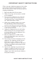
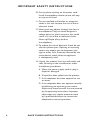
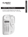
C4210™ User Guide
2.4 GHz Cordless Telephone with Caller ID
Featuring Digital Clarity Power Technology
E
N
G
L
I
S
H
TM
E
S
P
A
~
N
O
L
F
R
A
N
Ç
A
I
S
TABLE OF CONTENTS
Safety Instructions ....................................................... 5
Features ......................................................................... 9
Getting Started ..........................................................11
Choosing a Location ...........................................11
Telephone Installation ........................................12
Battery Installation .............................................14
Handset Battery Charging ................................14
Low Battery .........................................................14
Battery Life ...........................................................15
Headset Jack.........................................................15
Belt Clip ................................................................15
Hearing Aid Compatibility .................................15
Feature Set Up ...........................................................16
Handset Features ................................................16
Set Up Mode..................................................16
Digital Clarity Power ...................................19
Boost Clarity Power On/Off ......................19
Volume Control .............................................19
Tone Switch ....................................................19
Handset Ringer .............................................20
Pulse/Tone ......................................................20
Flash .................................................................20
Mute ................................................................20
Redial/Pause ...................................................20
Base Features .......................................................21
Ringer Volume ................................................21
Ringer Style ....................................................21
Visual Ringers .................................................21
Boost On/Off ................................................21
Battery Backup ..............................................22
TABLE OF CONTENTS
Telephone Operations .............................................24
Placing a Call ........................................................24
Answering a Call ..................................................24
Last Number Redial............................................24
Pause Feature .......................................................25
Temporary Tone ...................................................25
Lighted Key Pad ...................................................25
Page/Handset Locator........................................25
Channel Operation .............................................26
Security Code ......................................................26
Memory Storage ........................................................26
Review Phonebook Information ......................26
Adding a Phonebook Number..........................27
Dialing a Phonebook Entry ...............................28
Deleting a Stored Number ...............................28
Deleting All Stored Numbers ...........................28
Changing a Stored Number ..............................29
Adding the Emergency Number ......................29
Dialing the Emergency Number ......................30
Deleting the Emergency Number ...................30
Caller ID Operations ...............................................31
Caller ID Information ........................................31
Caller ID Review .................................................32
Saving Caller ID Information to Phonebook .33
Callback from Caller ID Information ..............34
Delete Caller ID Information ...........................36
Maintenance and Care .............................................37
Troubleshooting .........................................................37
Regulatory Compliance ...........................................40
Warranty and Service...............................................45
IMPORTANT SAFETY INSTRUCTIONS
When using your telephone equipment, basic safety
precautions should always be followed to reduce
the risk of fire, electric shock and injury to persons
including the following:
1. Read and understand all instructions.
2. Follow all warnings and instructions marked
on the telephone.
3. Do not use this telephone near a bath tub,
wash basin, kitchen sink or laundry tub, in
a wet basement, near a swimming pool or
any where else there is water.
4. Avoid using a telephone (other than a cordless type) during a storm. There may be a
remote risk of electrical shock from lightning.
5. Do not use the telephone to report a gas leak
in the vicinity of the leak.
6. Unplug this telephone from the wall outlets
before cleaning. Do not use liquid cleaners
or aerosol cleaners on the telephone. Use a
damp cloth for cleaning.
7. Place this telephone on a stable surface.
Serious damage and/or injury may result if
the telephone falls.
8. Do not cover the slots and openings on this
telephone. This telephone should never be
placed near or over a radiator or heat
register. This telephone should not be placed
in a built-in installation unless proper ventilation is provided.
9. Operate this telephone using the electrical
voltage as stated on the base unit or in the
owner’s manual. If you are not sure of the
voltage in your home, consult your dealer or
local power company.
SAVE THESE INSTRUCTIONS
5
IMPORTANT SAFETY INSTRUCTIONS
10. Do not place anything on the power cord.
Install the telephone where no one will step
or trip on the cord.
11. Do not overload wall outlets or extension
cords as this can increase the risk of fire or
electrical shock.
12. Never push any objects through the slots in
the telephone. They can touch dangerous
voltage points or short out parts that could
result in a risk of fire or electrical shock.
Never spill liquid of any kind on
the telephone.
13. To reduce the risk of electrical shock, do not
take this phone apart. Opening or removing
covers may expose you to dangerous voltages or other risks. Incorrect reassembly can
cause electric shock when the appliance
is subsequently used.
14. Unplug this product from the wall outlet and
refer servicing to the manufacturer under
the following conditions:
A. When the power supply cord or plug is
frayed or damaged.
B. If liquid has been spilled into the product.
C. If the telephone has been exposed to rain
or water.
D. If the telephone does not operate normally
by following the operating instructions.
Adjust only those controls that are covered
by the operating instructions. Improper
adjustment may require extensive work
by a qualified technician to restore the
telephone to normal operation.
6
SAVE THESE INSTRUCTIONS
IMPORTANT SAFETY INSTRUCTIONS
E. If the telephone has been dropped or the
case has been damaged.
F. If the telephone exhibits a distinct change
in performance.
15. Never install telephone wiring during a
lightning storm.
16. Never install telephone jacks in wet locations
unless the jack is specifically designed for
wet locations.
17. Never touch uninsulated telephone wires or
terminals unless the telephone line has been
disconnected at the network interface.
18. Use caution when installing or modifying
telephone lines.
19. Use only the power cord and batteries
indicated in the manual. Do not dispose
of batteries in a fire. They may explode.
Check with local codes for possible special
disposal instructions.
20. Plug the AC adaptor into the outlet that is
nearest and most accessible to the telephone.
SAVE THESE INSTRUCTIONS
7
IMPORTANT SAFETY INSTRUCTIONS
SAFETY INSTRUCTIONS FOR BATTERIES
Caution: Risk of explosion if battery is replaced by
an incorrect type. Dispose of used batteries
according to the instructions.
1. Use only the approved battery pack in the
handset of your cordless phone.
For Handset Unit: 3.6V 600mAHr
NiMH Rechargeable Battery
Sanik Battery Co. Ltd.: 3SNAAA60HSJ1
GPI International Ltd.: GP60AAAH3BMJZ
For Base Unit:
Four (4) AA alkaline batteries
2. Do not dispose of the battery in a fire as it
may explode. Check with local codes for
possible special disposal instructions.
3. Do not open or mutilate the battery.
Released electrolyte is corrosive and may
cause damage to the eyes and skin. It may
be toxic if swallowed.
4. Exercise care in handling batteries in order
not to short the battery with conducting
materials such as rings, bracelets and keys.
The battery or conduction material may
overheat and cause burns.
5. Charge the battery (ies) provided with or
identified for use with this product only in
accordance with the instructions and
limitations specified in this manual.
6. Observe proper polarity orientation between
the battery pack and the battery charger.
8
SAVE THESE INSTRUCTIONS
FEATURES
Telephone Base
1.
2.
3.
4.
5.
6.
7.
Handset Page
Ringer Volume
Ringer Style
Ringer On/Off
Antenna/Visual Ringer
Pulse/Tone
Boost On/Off
5
7
6
1
4
3
2
9
FEATURES
Handset
1.
2.
3.
4.
5.
6.
7.
8.
9.
10.
11.
12.
13.
14.
15.
16.
17.
18.
19.
20.
Neckloop Jack
Handset Tone
Boost
Handset Volume
Mute
Talk
Dial Pad
LCD Screen
Up/Down Arrow Keys
Mode
Program
Enter
Flash
Emergency Button
Redial/Pause
Visual Ringer
Handset Ringer Off/Vibe/On
Delete/Channel
Belt Clip
Headset Jack
20
1
16
8
2
9
3
5
10 17
4
6
11
12
19
7
13
10
18
14
15
GETTING STARTED
CHOOSING A LOCATION
1. This phone requires a modular phone
jack (RJ11C) and a standard 120V AC
wall outlet.
2. Plug the AC Adapter directly into outlet.
3. Do not plug other appliances into the
same outlet or have outlet controlled by a
wall switch.
TEL
4. Choose a location that is out of the way of
normal activities.
9V DC
400 mA
USE ONLY WITH CLASS
(CLASSE) 2 POWER SOURCE
CAUTION: USE ONLY WITH CLASS
2 POWER SOURCE 9V DC, 400MA.
Always connect the AC Adapter to the phone before
you connect it to the AC power. When you finish,
disconnect the AC power before you disconnect it
from the phone.
Connecting telephone
line cord
CONNECTING YOUR TELEPHONE
Carefully remove your cordless telephone from its
box. If there is any visible damage, do not attempt
to operate this equipment. Return it to the place of
purchase. Check to be sure that you have all items
that come with your telephone.You should have a
HANDSET, BASE UNIT, BATTERY, AC ADAPTER,
TELEPHONE LINE CORD, BELT CLIP and
OWNERS MANUAL.
If at any time you have questions about your
telephone please contact our Customer Service
Department at: 1-800-552-3368 or 423-622-7793.
TEL
9V DC
400 mA
USE ONLY WITH CLASS
(CLASSE) 2 POWER SOURCE
Connecting AC Adapter
11
GETTING STARTED
TABLE/DESK TOP INSTALLATION
CAUTION: Disconnect the telephone line cord
before connecting or disconnecting the battery
backup in the wall mount bracket.
1. Plug one end of the supplied modular telephone line cord into the jack marked TEL
located on the back of the telephone base
as shown in the diagram.
2. Plug the modular telephone line cord’s other
end into a modular phone jack.
3. Insert the supplied AC Adapter’s plug into the
jack marked 9V DC 400mA located on the
back of the telephone base.
4. Plug the adapter into a standard 120V AC
power (electrical) outlet.
5. Align the mounting bracket on the back of
the base so that the black rubber feet are
towards the bottom of the phone. Insert the
bracket’s tabs into the slots and secure the
bracket by sliding it upward.
6. Lift the base’s antenna to a vertical position.
7. Set the TONE/PULSE switch located on the
back of the base to correct dialing mode.
Please check with your local Phone Company
if uncertain of the type of service.
8. Place handset in the cradle to begin
initial charging.
WALL MOUNTING INSTALLATION
CAUTION: Disconnect the telephone line cord
before connecting or disconnecting the battery
backup in the wall mount bracket.
The base unit may be mounted on a standard
wall plate.
12
GETTING STARTED
1. Plug one end of the supplied short modular
telephone line cord into the TEL jack located
on the back of the base of the phone.
2. Insert the plug of the AC adapter into the
jack marked DC 9V 400mA located on the
back of the telephone base.
3. Align the mounting bracket on the back of
the base so that the black rubber feet are
towards the bottom of the phone. Insert the
bracket’s tabs into the slots and secure the
bracket by sliding it upward.
4. Plug the short modular telephone line cord
into the wall plate jack, then align the mounting
bracket’s keyhole slots with the wall plate
studs and slide the base of the phone downward to secure it on the wall.
5. Plug the adapter into a standard AC power
(electrical) outlet.
6. Press and lift out the handset holder tab, turn
it around so the narrow tab end extends out
and slide back into its slot. This will hold the
handset in the cradle when the phone is
wall mounted.
7. Lift the base’s antenna to a vertical position.
8. Set the Tone/Pulse switch located on the
end of the base to correct dialing mode.
Please check with your local Phone Company
if uncertain of the type of service.
9. Place handset in the cradle to begin initial
charging. Remember, you must charge the
phone for at least 12 hours before you use
the phone for the first time.
Note: Remember, you must charge the phone for
at least 12 hours before you use the phone for the
first time.
13
GETTING STARTED
HANDSET BATTERY INSTALLATION
The C4210 uses a 3.6Volt 600mAh NiMH rechargeable 3 cell (AAA Type) battery that is included with
your unit.
Handset Battery must be connected before
beginning initial charging.
To Install a New Battery
1.
2.
3.
4.
5.
Battery
Connector
Battery
Pack Plug
Remove battery cover
Install new battery
Connect battery pack
Replace battery cover
Charge for 12 hours before first use
Handset Battery Charging
1. Place the handset in the base. The
CHARGE LED on the base will light RED.
2. After the batteries are fully charged,
check for dial tone by pressing TALK on
the handset.
Battery
Compartment
Cover
Installing and
connecting battery
Note:The battery in the
handset must be fully charged
for 12 hours before using the
telephone for the first time.
Low Battery
When the handset battery gets low, there will be
two (2) beeps every thirty (30) seconds. If the battery becomes low while you are on a call, you will be
disconnected after about two (2) minutes. Terminate
the call and recharge the battery. To recharge the
battery pack, place the handset in the base.
1. Make sure the contact points are touching
and the CHARGE LED is lit.
2. Be careful not to short battery with
Conducting materials such as rings,
bracelets and keys.
14
GETTING STARTED
Battery Life
A fully charged battery provides an average talk time
of about four (4) hours, or standby time of about (8)
days. Talk time and standby time may vary depending
on operating conditions.
Talk Time: about
four (4) hours
Standby Time: about
eight (8) days
Headset Jack
You can use this telephone hands-free when you
install a 2.5mm headset (purchased separately). To
install, plug the headset into the HEADSET JACK
at the top of the handset. While in headset mode,
the volume of headset is controlled by the telephone and the handset’s earpiece and microphone
are disconnected.
Ordering a Headset
In the event you wish to purchase a headset for your
C4210, please contact Plantronics at 1-800-544-4660
for a location near you. We recommend using the
Plantronics M110 or M130 headset.
Belt Clip
You may choose to use the optional belt clip with
your handset.
1. To attach slide belt clip down onto grooves.
Press the tabs on the belt clip into the slots
to attach.
2. To remove, lift one side of the belt clip with
your thumbnail and push back.
Hearing Aid Compatibility
The handset has a special coil inside of it to couple
the sound to hearing aids equipped with T-Switches/
T-Coils.
15
FEATURE SET UP
TELEPHONE HANDSET
Set-up Mode
The C4210 handset goes into setup mode automatically when the battery is connected.
Or press and hold MODE button for 3 seconds to
enter setup mode. If there is no input within 30
seconds, the language will be set to the last selected
one and go back to standby mode.
Setting Language
1. After entering setup mode, the LCD display
will show SEL LANGUAGE and then 1.ENG
2.SPA alternately with a tick mark against the
selected language.
2. Press the 1 or 2 button once to change the
language. The tick mark will move against the
new selection.
3. Press UP (▲) to go to the next menu.
Setting Contrast
There are 3 contrast levels and the default is set to
level 2.
1. After setting the language, press UP (▲) key
to begin setting contrast.
2. The LCD display will show LCD CONTRAST
and 1 2 3.
3. Press the 1, 2 or 3 key to change the level.
The current selected level will be highlighted.
4. Press the UP (▲) or DOWN (▼) button to go
to the next menu.
Setting Area Code 1
1. After setting Contrast, press UP (▲) button
to set Area Code 1.
16
2. The LCD display will show AREA CODE 1
and XYZ with X digit blinking.
FEATURE SET UP
3. Enter the area code number using the
numeric keys on the handset.
4. Press the UP (▲) or DOWN (▼) button to go
to the next menu.
Setting Area Code 2
1. After setting Area Code 1, press UP (▲)
button to set Area Code 2.
2. The LCD display will show AREA CODE 2
and XYZ with X digit blinking.
3. Enter the area code number using the
numeric keys on the handset.
4. Press the UP (▲) or DOWN (▼) button to go
to the next menu.
Setting Long Distance Service
(LDS) Code
1. After setting Area Code 2, press UP (▲)
button to set LDS Code.
2. The LCD display will show LDS CODE and X
with X digit blinking.
3. Enter the LDS number using the numeric keys
on the handset.
4. Press the UP (▲) or DOWN (▼) button to go
to the next menu.
Setting Easy Mode
1. After setting LDS Code, press UP (▲) button
to set the Easy Mode.
2. The LCD display will show EASY MODE and
1.ON 2.OFF.
3. Press 1 or 2 to change the mode. The tick
mark will move against the selected mode.
4. Press the UP (▲) or DOWN (▼) button to
change the mode.
17
FEATURE SET UP
Setting Voicemail Number
1. After setting Easy Mode, press UP (▲) button
to set VOICEMAIL Number.
2. The LCD display will show VOICEMAIL NO
and XXX-XXX-XXXX with the last
digit blinking.
3. Enter the voicemail number using the numeric
keys on the handset. Press DEL/CH key to
delete and move cursor back one place.
4. Press the UP (▲) or DOWN (▼) button to go
to the next menu.
Setting Message Waiting ON/OFF
1. After setting Voicemail No, press UP (▲)
button to set Message Waiting function
ON/OFF.
2. The LCD display will show MESSAGE,
WAITING, and 1.ON 2.OFF with a tick
mark against the selected item.
3. Press 1 or 2 button to change the mode.
4. Press the UP (▲) or DOWN (▼) button to go
to the next menu.
Setting Autoconnect ON/OFF
1. After setting Message Waiting Light ON/OFF,
press UP (▲) button to set
AUTOCONNECT ON/OFF (default to ON).
2. The LCD display will show AUTOCONNECT,
1.ON 2.OFF.
3. Press 1 or 2 to change or current selected
value. The tick mark will move against the
selected value.
4. Press the UP (▲) or DOWN (▼) button to go
to the next menu.
18
FEATURE SET UP
Digital Clarity Power™ Technology
With Digital Clarity Power, the high frequency
sounds are amplified more than the low frequency
sounds so words are not just louder, but clearer and
easier to understand. It also provides intelligent
amplification to make soft sounds audible, while
keeping loud sounds bearable.
BOOST – Clarity Power On/Off
The C4210 has a button that controls the loudness
of the receiver. Once the BOOST button is pressed,
an extra level of amplification is added over the
entire range of the volume control.
The TALK button will light ORANGE to indicate the
CLARITY POWER feature is activated.
WARNING: When the TALK button is lit ORANGE
volume may be at a high level. To protect
hearing, lower the volume control to minimum
before using.
Volume Control
The dial controls the level of volume the handset and
headset receive. The volume dial provides up to 15
dB of volume before the CLARITY POWER button
is activated. Once the CLARITY POWER button
is pressed, the C4210 will provide up to 50 dB of
amplification.
Tone Switch
The C4210 has three (3) TONE settings. Adjusting
the TONE switch changes the style of amplification
and allows you to customize your hearing experience. We all have different hearing preferences. We
suggest exploring each setting to find the one you
find most comfortable.
19
FEATURE SET UP
Handset Ringer
Set the switch marked Ringer OFF/VIBE/ON located
on the side of the handset. When VIBE is selected
the handset will ring and vibrate when receiving and
incoming call. The ringer switch must be set to ON
or VIBE for the handset
to ring.
Note: If both handset and base ringers are set to
OFF, the visual ringer will flash to indicate there is an
incoming call.
Pulse/Tone
Slide the switch to the type of telephone service you
have; TONE for touch-tone service or PULSE for
rotary dialing. Please check with your local telephone
company if uncertain of the type of service.
Flash
The FLASH button is activated to use custom calling
services such as Call Waiting or Three-Way Calling.
Please contact your local telephone company for
information on these services.
Mute
The MUTE button allows the user to conduct a
private conversation that you do not want the
person on the other end to hear. While in the mute
mode, the MUTE button will illuminate RED and the
microphone in the handset is disabled. Pressing the
MUTE button again will disengage the MUTE feature.
Redial/Pause
Press the RD/P button to redial the last number
dialed. Pressing the RD/P button while storing a
telephone number will insert a four (4) second
pause. This is commonly used when storing both the
telephone number and an extension or PIN number.
20
FEATURE SET UP
TELEPHONE BASE
Ringer Volume
The base ringer volume adjustments are located on
the side of the telephone base.
Pressing the UP (▲) key on the base increases the
ringer sound by one level while pressing the DOWN
(▼) key reduces the sound by one level. There are a
total of six levels from maximum to minimum. The
ringer will sound for two (2) seconds while choosing
a ringer volume, to allow the user to make a choice.
Ringer Style
The base ringer style adjustments are located on the
side of the telephone base. The style of ring can be
adjusted by pressing the RING STYLE button. Six (6)
styles are available allowing you to customize your
ring. The ringer will sound for two (2) seconds while
choosing a ringer style, to allow the user to make a
choice.
Visual Ringers
Visual ringers are located in both the handset
antenna and the base of the telephone. When an
incoming call is received, these lights will flash. The
handset visual ringer will also stay lit while the phone
is in use.
BOOST ON/OFF Switch
This switch will disable the reset feature of the
BOOST Clarity Power button as follows:
ON – When the BOOST ON/OFF switch is set to
ON, the Boost function will be ON every time a call
starts, and will default to ON every time the phone
hangs up. During a call, the BOOST Clarity Power
button can toggle the Clarity Power ON or OFF
according to the user’s needs.
21
FEATURE SET UP
OFF – When the BOOST ON/OFF switch is set to
OFF, the Boost function will be OFF every time a call
starts, and the user will need to press the BOOST
Clarity Power button in order to gain the extra level
of amplification. If the phone hangs up, the Clarity
Power will reset to OFF. During a call, the BOOST
Clarity Power button can toggle the Clarity Power
function ON or OFF according to the user’s needs.
CAUTION:VOLUME WILL BE LOUD
WHEN BOOST SWITCH IS SET TO “ON.”
Battery Back-up
Installing four (4) AA Alkaline batteries into the
desk/wall mount bracket attached to the telephone
base will offer you a limited amount of time to continue operating your telephone in the event of
a power failure.
To Install Battery Back-up Batteries
1. Disconnect telephone line cord and
remove desk/wall mount bracket from
telephone base.
2. Disconnect battery back-up connector from
the telephone base.
3. Install four (4) AA Alkaline batteries
with negative (-) end of battery touching
the spring.
4. Connect battery back-up connector to
terminal on bottom of telephone base.
5. Install desk/wall mount bracket to
telephone base.
22
FEATURE SET UP
To Replace Battery Backup Batteries
1. Disconnect telephone line cord and
remove desk/wall mount bracket from
telephone base.
2. Disconnect battery back-up connector from
the telephone base.
3. Remove batteries from desk/wall
mount bracket.
4. Install four (4) AA Alkaline batteries with
negative (-) end of battery touching
the spring.
5. Connect battery back-up connector to
terminal on bottom of telephone base
6. Install desk/wall mount bracket to
telephone base
After installing the four (4) AA Alkaline batteries
please refer to the chart below:
Power Supply
Power LED Status
AC adapter and
good batteries
Steady Green
AC adapter and
no batteries
Steady Red
AC adapter and
bad batteries
Flashing green and red
Power failure and
good batteries
Slow flashing red
Power failure and
bad batteries
Fast flashing red
23
TELEPHONE OPERATIONS
Placing a Call
1. Press the TALK button (TALK button will
illuminate GREEN) and dial the number you
wish to call.
2. To end the call press the TALK button or place
the handset in the base.
Or
1. Press the keys of the numbers needed to dial.
The LCD will display PREDIAL and the
keys pressed.
2. Press the TALK button. Handset will go offhook and dial the displayed numbers.
Answering a Call
If the handset is out of the cradle, press the
TALK button.
If the handset is in the cradle with Auto-Connect
Mode ON, lift the handset. The handset will be in
receiver mode.
If the handset is in the cradle with AutoConnect
mode OFF, lift the handset. The handset will be in
standby mode. Press TALK button to receive
the call.
Refer to BOOST Clarity Power and Volume Control
for information on adjusting volume controls on
Page 19.
Last Number Redial
The last number dialed (up to 32 digits) is stored in
the redial memory until another number is dialed.
To use this feature:
1. Press the TALK button.
2. When you hear the dial tone, press the
RD/P button.
24
3. The phone will automatically dial for you.
TELEPHONE OPERATIONS
Pause Feature
Programming in a pause will cause the phone to wait
four (4) seconds before dialing additional numbers.
This feature may be used when it is necessary to dial
an access code (9, for example) and wait for a second dial tone before you can dial an outside number.
Press the RD/P button at the required point during
the memory storage process to program a pause.
Temporary Tone
If you have rotary (pulse) dial service, you can change
from pulse to touch tone (tone) during a call.
1. Make phone call and wait until it
is connected.
2. Press the * key. Keys pressed after this are
sent as tone signals.
3. The phone will automatically reset to rotary
(pulse) service after the call ends.
Lighted Key Pad
The key pad will light for fifteen (15) seconds after
removing the handset from the base. To reactivate
the feature while in standby, press the TALK or the
MEM button. To activate while the phone is in use,
press any key.
Page/Handset Locator
To send a page signal from the base to the handset,
press the PAGE button located on the base of
the telephone. A series of rings will sound from
the handset.
To locate the handset if it is away from the base,
press and hold the PAGE button for approximately
five (5) seconds. A series of rings will sound. Return
the handset to the base or press any
button to cancel the page.
25
TELEPHONE OPERATIONS
Channel Operation
The C4210 cordless telephone automatically
searches and selects the clearest of 40 channels
when it is being used. If interference develops on the
line, pressing this button will move to
another channel.
Security Code
The security code prevents your cordless phone
conversations from being accessed by a phone on
a different line. Once the handset battery is fully
charged, the handset will automatically select the
code from over 65,000 different combinations. The
code is changed every time the handset is placed in
the cradle. If you have trouble with placing or receiving calls, a lost security code may be the cause of
the problem. When this occurs, the handset can no
longer communicate with the base.
MEMORY STORAGE
Review Phonebook Information
1. Unit must be in standby mode only.
2. Press MODE key twice. The LCD will show
PHONEBOOK.
3. If the phonebook is empty, after 1 second the
display shows - NO RECORDS -.
4. Otherwise, the display will show the first
alphabetical record with the record number
on the top icon line. The record number may
not be the first one.
5. Press the UP (▲) or DOWN (▼) button to go
to the next record. Or select any other alphabetical list pressing “2” to “9” key.
6. When at the end of the list, pressing DOWN
(▼) button will show END OF LIST. Press the
UP (▲) button to go to the last record.
26
TELEPHONE OPERATIONS
Adding a Phonebook Number
1. Unit must be in standby mode only.
2. Press MODE key twice. The display will show
PHONEBOOK for 1 second and
then display the first available record.
3. Press PROG key to add new phone record.
4. If the phonebook is full, the display will show
PHONEBOOK FULL for 1 second together
with an error keynote. Then return to
review mode.
5. If memory is available, the display will show
SAVE NEW NUM and then ENTER NUMBER.
6. After pressing any number key, the second
line will change to ENTER TO END and
the third line shows the number(s) pressed.
Enter phone number up to 23 digits, (RD/P)
treated as Pause, counted as one digit, shown as
(P). Press DEL/CH to erase any mistake.
7. Press ENTER to confirm number. The LCD will
display ENTER NAME and then the second
line is blanked.
8. Enter name up to 21 characters using
keys 2 to 9.
• Press 2 once for A and twice for B.
• Press # to insert # or punctuation marks.
• Use RD/P key to insert a space between
alphabets.
• Press DEL/CH key to erase any mistake.
The cursor will move forward one space
automatically.
9. Press ENTER to confirm name. The LCD will
display NUMBER STORED. Then it displays the
just entered information.
27
TELEPHONE OPERATIONS
Dialing a Phonebook Entry
1. Locate the phonebook record you wish
to call.
2. Press TALK or ENTER button to dial the
displayed number.
Deleting a Stored Number
1. Unit must be in standby mode and display
is showing a phonebook record.
2. Press DEL/CH key once. The LCD will
show DELETE?
3. Press DEL/CH to confirm.
4. The display will show MEM DELETED for 3
seconds together with a success keynote.
5. The display will show the next available
record or -NO RECORDS-.
• If the memory location is empty, pressing
DEL key will have no action.
• This sequence will time-out after 30
seconds if no key is pressed.
Deleting All Stored Numbers
1. Unit must be in standby mode and display is
showing a valid phone record.
2. Press and hold DEL/CH button for 3 seconds
to delete all phonebook records. Display will
flash DELETE ALL?.
3. Press DEL/CH to confirm. Display will show
-NO RECORDS- for 2 seconds together with
a success keynote.
• If the memory location is empty, pressing
DEL key will have no action.
• This sequence will time-out after 30
seconds if no key is pressed.
28
TELEPHONE OPERATIONS
Changing a Stored Number
1. Unit must be in standby mode only.
2. Press MODE key twice. The display will show
PHONEBOOK for 1 second and then display
the first available record.
3. Press the UP (▲) or DOWN (▼) button to go
to the record to be changed, e.g. ABC, 567
4. Press # key to change the phone record.
5. The display will show ENTER TO END and
the stored number 567 with the blinking
cursor after the digit 7.
6. Press any numeric key to add extra numbers.
Or
Press DEL/CH key to move the cursor to the
digit 7. Then press other numeric key to
replace 7.
7. Press ENTER after finishing the digits.
8. The display shows ABC with the cursor
blinking after the character C.
9. Press any numeric key 2 to 9 to add
extra characters.
Or
Press DEL/CH key to move the cursor back
to character C. Then press any other
numeric key to change this character.
10. Press ENTER to finish. The modified
characters and numbers will replace the
original phone record.
11. The display will show NUMBER STORED.
Adding the EMERGENCY Number
1. Unit must be in standby mode only.
2. Press MODE key twice. The display will show
PHONEBOOK for 1 second and then display
the first available record.
29
TELEPHONE OPERATIONS
3. Press the UP (▲) or DOWN (▼) button
to go to the record to be stored to the
EMERGENCY key.
4. Press and hold the EMERGENCY key for
2 seconds.
5. The phone number is copied to the
EMERGENCY key. The LCD will display MEM
STORING for one (1) second and the
handset will give a success keynote.
Dialing the EMERGENCY Number
1. Unit must be in standby mode only.
2. Press the EMERGENCY key once.
3. The display will show the stored name and
number for 5 seconds. Otherwise it will show
-MEMORY EMPTY-.
4. Then the handset goes off-hook and dial out
the stored numbers.
Or
5. Press TALK key to make handset goes off-hook.
6. Press the EMERGENCY key once. The display
will show the stored name and number for 1
sec. Then the numbers will be sent out.
Deleting the EMERGENCY Number
1. Unit must be in standby mode.
2. Press the EMERGENCY key once.
3. If this key has been programmed, the display
will show the stored number. Otherwise, it
will show MEMORY EMPTY.
4. Press DEL/CH key once to delete number.
5. The display will flash DELETE?.
6. Press DEL/CH to delete. The handset will
give a success keynote and the display will
show MEM DELETED.
30
TELEPHONE OPERATIONS
CALLER ID OPERATIONS
Visual Message Waiting Indicator (VMWI)
Note: This is a service that is provided through your
local telephone company.
If the C4210 finds that there is voice message to be
retrieved, it will turn on the Message Waiting Indicator (the ENTER key).
To retrieve the voice message, press the ENTER key
while the indicator is on. The handset will go offhook and dial the stored Voicemail number.
CALLER ID Information
This function is turned off when EASY MODE is set
to ON during setup.
Caller Information
When somebody calls, the received caller information is displayed on the LCD. If the call is answered
by this phone, this caller information is considered
“old”. Otherwise, the Caller ID information will be
stored in the call log. Information which has not been
reviewed will be considered as “new call”.
The NEW CALL LED will blink. The top row displays
the time and date of the call. The second row displays
the caller’s ID or is blank if there is no information.
The third row displays the incoming telephone number. If the number is longer than twelve (12) digits,
the LCD will toggle the displayed number between
the first 12 digits and the remaining digits.
Receiving Call Waiting Caller ID
When you are on an existing call, you will hear a
beep and the display will show incoming call waiting
Caller ID information.
31
TELEPHONE OPERATIONS
If you access the call waiting call, the Caller ID
information will disappear and the Time/Day screen
will appear.
If you do not access the call waiting call, the Caller
ID information will be transferred into the Caller log.
This caller information is considered “old”.
Unknown Call
If a call is from another country or the caller’s
number is not available, UNKNOWN is displayed
and stored in the Caller ID log.
Blocked Call
If the number is blocked or withheld, PRIVATE is
displayed and stored in Caller ID log.
Repeated Call
If this is a repeated call, it means the same number
called before and has not been reviewed.
CALLER ID Review
If there is new call information, the MODE button
will flash RED.
During standby mode, press MODE button once.
LCD will display CID MODE and then the last Caller
ID information.
Press UP (▲) or DOWN (▼) again to view the
Caller ID content. Press DOWN (▼) to scroll the
caller ID information from the most recent record.
Or, press the UP (▲) button to scroll the Caller ID
information from the oldest record.
If the caller’s number is more than (12) digits, the
LCD will toggle the displayed message between the
first 12 digits and the remaining digits.
32
TELEPHONE OPERATIONS
If the Caller ID list is empty, the display will show
- NO CALLS -.
• At anytime, the user can press FLASH button
one time to go back to standby mode.
Or
• It will go back to standby automatically at
30 seconds time out if there is no action.
Saving CALLER ID Information to
Phonebook
1. While reviewing Caller information, press
PROG key once.
2. The display shows SAVE TO PHONEBOOK.
Then it changes to ENTER TO END, and the
Caller number on the third line with the blinking cursor at the end of the number.
3. Use numeric key to add extra numbers. Press
DEL/CH to erase any mistakes.
Or
Press DEL/CH to move cursor back one digit.
Then press any other numeric key to replace
the number.
4. Press ENTER to confirm the number.
5. The display shows ENTER NAME first and
then the Caller’s name on the second line
with blinking cursor at the end. The entered
number is displayed on the third line.
6. Press 2-9 keys to add extra characters. Press
DEL/CH to erase any mistakes.
Or
Press DEL/CH to move cursor back one character. Then press any other numeric key to
replace the character.
7. Press ENTER to confirm the name.
8. The display will show NUMBER STORED
first. Then it shows the name and number
just saved.
33
TELEPHONE OPERATIONS
• At anytime, the user can press FLASH
button one time to go back to
standby mode.
Or
• It will go back to standby automatically at
30 seconds time out if there is no action.
Callback from CALLER ID Information
To callback from incoming call information, the base
T/P switch should be set at T.
While reviewing the incoming call list, press
ENTER and the UP (▲) or DOWN (▼) key will
format the number with the following
dialing variations:
• 7 digits without a 1 prefix:
If the area code of the Caller ID number
matches to the setting of the stored area
code, the dialed numbers can be 7
digits only.
• Area Code + 7 digits without a 1 prefix:
If the area code of the Caller ID number
matches to the setting of the stored area
code, the dialed numbers can be Area
Code + 7 digits.
• 10 digits without a 1 prefix:
If the area code of the Caller ID number is
different from the stored area code, the
dialed numbers can be 10 digits without a
1 prefix.
• 10 digits with a 1 prefix:
If the area code of the Caller ID number is
different from the stored area code, the
dialed numbers can be 1 + 10 digits.
When reviewing the Caller ID information, press
ENTER to display the phone number in a
different format.
34
TELEPHONE OPERATIONS
Example 1:
Stored Long Distance Service code: 1.
Stored area code: 770.
Stored incoming call number 770-123-4567.
1. Pressing the ENTER key will show blinking
123-4567.
2. Pressing the TALK or ENTER key again will
dial out 1234567.
Or
3. Pressing the UP (▲) key will show blinking
770-123-4567. Then press the TALK or
ENTER key again will dial out 7701234567.
Or
4. Pressing the UP (▲) key will show blinking
1-7701234567. Press the TALK or ENTER
key will dial out 17701234567.
Or
5. Pressing the UP (▲) key will show blinking
123-4567 again.
Example 2:
Stored Long Distance Service code: 1.
Stored area code: 770.
Stored incoming call number 413-456-7890.
1. Pressing the ENTER key will show blinking
413-456-7890.
2. Pressing the TALK or ENTER key again will
dial out 4134567890.
Or
3. Pressing the UP (▲) key will show blinking
1-413-456-7890. Press the TALK or ENTER
key will dial out 14134567890.
Or
35
TELEPHONE OPERATIONS
4. Pressing the UP (▲) key will show blinking
413-456-7890 again.
Delete Caller ID Information
While reviewing the Caller ID, press DEL/CH button
to delete the displayed caller information. LCD will
flash DELETE ?.
Press DEL/CH to confirm. CID DELETED will be
displayed for 2 seconds. The next record is shown
automatically or - NO CALLS - if the list is empty.
• At anytime, the user can press FLASH button
one time to go back to standby mode.
Or
• It will go back to standby automatically at
30 seconds time out if there is no action.
Deleting All Caller ID Information
While reviewing the Caller ID, press and hold the
DEL/CH button for two seconds. LCD will flash
DELETE ALL?. Press DEL/CH to confirm. LCD will
display ALL CID and DELETED for 2 seconds and
then - NO CALLS -.
• At anytime, the user can press FLASH button
one time to go back to standby mode.
Or
• It will go back to standby automatically at
30 seconds time out if there is no action.
The C4210 has been designed to give you years
of dependable service with a minimum of care. To
ensure the utmost in performance, follow these
guidelines in caring for the unit:
1. Avoid dropping or knocking the unit.
2. Dust the unit regularly. Wipe the unit with a
soft damp cloth.
36
MAINTENANCE AND CARE
3. Do not use detergents and avoid
excess moisture.
4. The C4210 is an electrical device. Avoid
electric shock by keeping the phone away
from water (i.e. bathroom, kitchen sink, etc.).
The unit will not operate/no dial tone:
•
Verify the TALK Button is lit.
•
Verify the AC Adapter is securely plugged
into AC outlet, the base and the telephone.
•
Verify the telephone line cord is securely
plugged into the wall jack and the telephone.
•
Make sure the base antenna is in an
upright position.
•
Make sure the handset battery is fully charged.
•
Verify the telephone is in the correct dialing
mode, tone (touch) or pulse (rotary).
•
Make sure you are in the usable range of the
base station.
•
Reset the security code by placing the handset
in the base for 5-10 seconds.
The phone does not ring when you
receive a call:
•
Make sure the RINGER switch on the handset
and base are set to ON.
•
Verify the AC Adapter is securely plugged into
AC outlet, the base and the telephone.
•
Verify the telephone line cord is securely
plugged into the wall jack and the telephone.
•
Make sure you are in the usable range of the
base station.
• You may have too many extensions on your
line. Try unplugging a few devices.
37
TROUBLESHOOTING
Noise, Static, Interference or Other Calls
Heard while Using the Handset:
•
Try changing channels.
•
Make sure the base antenna is in an
upright position.
•
Make sure you are in the usable range of the
base station.
•
Make sure the handset battery is fully charged.
•
Try relocating the base unit to another location.
•
Make sure the AC Adapter is not plugged into
the wall outlet with other appliances.
Phone Will Not Hold Charge:
38
•
Make sure the charging contacts on the
handset and base are free of dust and dirt.
Clean the contacts with a soft cloth.
•
Make sure CHARGE LED on the base is lit
when handset is in the cradle.
•
If necessary, replace the handset battery. (See
Handset Battery Charging)
TROUBLESHOOTING
Difficulty in Placing or Receiving Calls:
•
Move closer to the base and try again.
•
If moving closer does not work, you may have
lost the security code.
•
Reset code by placing the handset back on
the base for 5-10 seconds. (See Security
Code Section)
•
Make sure you have selected the correct
dialing mode, tone or pulse.
•
Make sure the AC Adapter is not plugged into
a wall outlet with other appliances. Disconnect for 5-10 seconds then reconnect. Place
the handset back on the base and reinsert the
AC Adapter.
•
Make sure the handset battery is fully charged.
39
REGULATORY COMPLIANCE
Part 68 of FCC Rules Information
a) This equipment complies with Part 68 of the FCC
rules and the requirements adopted by the ACTA.
On the bottom of this equipment is a label that
contains, among other information, a product
identifier in the format US:AAAEQ##TXXXX. If
requested, this number must be provided to the
telephone company.
b) A plug and jack used to connect this equipment
to the premises wiring and telephone network must
comply with the applicable FCC Part 68 rules and
requirements adopted by the ACTA. A compliant
telephone cord and modular plug, RJ11C USOC,
is provided with this product. It is designed to be
connected to a compatible modular jack that is also
compliant. See installation instructions for details.
c) The REN is used to determine the number of
devices that may be connected to a telephone line.
Excessive RENs on a telephone line may result in the
devices not ringing in response to an incoming call. In
most but not all areas, the sum of RENs should not
exceed five (5.0). To be certain of the number of devices that may be connected to a line, as determined
by the total RENs, contact the local telephone company. For products approved after July 23, 2001, the
REN for this product is part of the product identifier
that has the format US:AAAEQ##TXXXX.
The digits represented by ## are the REN without
a decimal point (e.g., 03 is a REN of 0.3). For earlier
products, the REN is separately shown on the label.
d) If this telephone equipment causes harm to
the telephone network, the telephone company will
notify you in advance that temporary discontinuance
of service may be required. But if advance notice isn’t
practical, the telephone company will notify the
40
REGULATORY COMPLIANCE
customer as soon as possible. Also, you will be
advised of your right to file a complaint with the
FCC if you believe it is necessary.
e) The telephone company may make changes
in its facilities, equipment, operations or procedures
that could affect the operation of the equipment. If
this happens the telephone company will provide
advance notice in order for you to make necessary
modifications to maintain uninterrupted service.
f) If trouble is experienced with this telephone
equipment, for repair or warranty information, please
contact Clarity, 1-800-552-3368. If the equipment is
causing harm to the telephone network, the telephone company may request that you disconnect the
equipment until the problem is resolved.
g) This telephone equipment is not intended to be
repaired and it contains no repairable parts. Opening
the equipment or any attempt to perform repairs
will void the warranty. For service or repairs, call
1-800-552-3368.
h) Connection to party line service is subject to
state tariffs. Contact the state public utility
commission, public service commission or
corporation commission for information.
i) If your home has specially wired alarm equipment
connected to the telephone line, ensure the installation of this telephone equipment does not disable
your alarm equipment. If you have questions about
what will disable alarm equipment, consult your
telephone company or a qualified installer.
j) This telephone equipment is hearing
aid compatible.
41
REGULATORY COMPLIANCE
Customer-Owned Coin/Credit Card
Phones:
To comply with state tariffs, the telephone company
must be given notification prior to connection. In
some states, the state public utility commission, public service commission or corporation commission
must give prior approval of connection.
Part 15 of FCC Rules Information
This device complies with Part 15 of the FCC Rules.
Operation is subject to the following two conditions:
(1) This device may not cause harmful interference,
and (2) this device must accept any interference
received, including interference that may cause
undesired operation.
Your equipment has been tested and found to
comply with the limits of a Class B digital device,
pursuant to Part 15 of FCC rules. These limits are
designed to provide reasonable protection against
harmful interference in residential installation.
This equipment generates, uses and can radiate radio
frequency energy and, if not installed and used in accordance with the instructions, may cause harmful interference to radio communications. However, there
is no guarantee that interference will not occur in a
particular installation; if this equipment does cause
harmful interference to radio or television reception,
which can be determined by turning the equipment
off and on, you are encouraged to try to correct the
interference by one of the following measures:
1. Where it can be done safely, reorient the
receiving television or radio antenna.
2. To the extent possible, relocate the television,
radio or other receiver with respect to the
telephone equipment. (This increases the
separation between the telephone equipment
and the receiver.)
42
REGULATORY COMPLIANCE
3. Connect the telephone equipment into an
outlet on a circuit different from that to which
the television, radio, or other receiver is
connected.
4. Consult the dealer or an experienced Radio/
TV Technician for help.
CAUTION: Changes or modifications not expressly approved by the manufacturer responsible for
compliance could void the user’s authority to operate the equipment.
Industry Canada Technical Specifications
This product meets the applicable Industry Canada
technical specifications.
Before installing this equipment, users should ensure
that it is permissible to be connected to the facilities of the local telecommunications company. The
equipment must also be installed using an acceptable
method of connection. In some cases, the company’s
inside wiring associated with a single line individual
service may be extended by means of a certified
connector assembly (telephone extension cord). The
customer should be aware that compliance with the
above conditions may not prevent degradation of
service in some situations. Repairs to certified equipment should be made by an authorized Canadian
maintenance facility designated by the supplier.
Any repairs or alterations made by the user to this
equipment, or equipment malfunctions, may give the
telecommunications company cause to request the
user to disconnect the equipment.
Users should ensure for their own protection that
the electrical ground connections of the power utility, telephone lines and internal metallic water pipe
system, if present, are connected together. This precaution may be particularly important in rural areas.
43
REGULATORY COMPLIANCE
CAUTION: Users should not attempt to make
such connections themselves, but should contact the
appropriate electrical inspection authority, or electrician, as appropriate.
The Ringer Equivalence Number is an indication of
the maximum number of terminals allowed to be
connected to a telephone interface. The termination
on an interface may consist of any combination of
devices subject only to the requirement that the sum
of the Ringer Equivalence Numbers of all the devices
does not exceed five.
(The term “IC:” before the certification/
registration number only signifies that the Industry
Canada technical specifications were met.)
The party responsible for regulatory
compliance:
Clarity, A Division of Plantronics, Inc.
4289 Bonny Oaks Drive, Suite 106
Chattanooga, TN 37406
Phone: 1-800-552-3368
44
WARRANTY & SERVICE
The following warranty and service information applies only to products purchased and used in the U.S.
and Canada. For warranty information in other countries, please contact your local retailer or distributor.
Limited Warranty
Clarity, a division of Plantronics, Inc. (“Clarity”) warrants to the original consumer purchaser that, except
for limitations and exclusions set forth below, this
product shall be free from defects in materials and
workmanship for a period of one (1) year from the
date of original purchase (“Warranty Period”). The
obligation of Clarity under this warranty shall be at
Clarity‘s option, without charge, of any part or unit
that proves to be defective in material or workmanship during the Warranty Period.
Exclusions from Warranty
This warranty applies only to defects in factory
materials and factory workmanship.
Any condition caused by accident, abuse, misuse or
improper operation, violation of instructions furnished by Clarity, destruction or alteration, improper
electrical voltages or currents, or repair or maintenance attempted by anyone other than Clarity or
an authorized service center, is not a defect covered
by this warranty. Telephone companies manufacture
different types of equipment and Clarity does not
warrant that its equipment is compatible with the
equipment of a particular phone company.
45
WARRANTY & SERVICE
Implied Warranties
Under state law, you may be entitled to the benefit
of certain implied warranties. These implied warranties will continue in force only during the warranty
period. Some states do allow limitations on how long
an implied warranty lasts, so the above limitation may
not apply to you.
Incidental or Consequential Damages
Neither Clarity nor your retail dealer or selling
distributors has any responsibility for any incidental
or consequential damages including without limitation, commercial loss or profit, or for any incidental
expenses, expenses, loss of time, or inconvenience.
Some states do not allow exclusion or limitation of
incidental or consequential damage, so the above
limitation or exclusion may not apply to you.
Other Legal Rights
This warranty gives you specific legal rights and you
may also have other rights which vary from state to
state.
How to Obtain Warranty Service
To obtain warranty service, please prepay shipment
and return the unit to the appropriate facility listed
below.
In the United States
Clarity Service Center
4289 Bonny Oaks Drive, Suite 106
Chattanooga, Tennessee 37406
Tel: (423) 622-7793 or (800) 426-3738
Fax: (423) 622-7646 or (800) 325-8871
46
WARRANTY & SERVICE
In Canada
Plantronics Service Center
8112 Trans-Canada Hwy.
Ville St. Laurent. Que.
Canada H4S 1M5
Tel: (800) 540-8363
(514) 956-8363
Fax: (514) 956-1825
Please use the original container, or pack the unit(s)
in a sturdy carton with sufficient packing material to
prevent damage.
Include the following information:
1. A proof-of-purchase indicating model number
and date of purchase.
2. Bill-to address.
3. Ship-to address.
4. Number and description of units shipped.
5. Name and telephone number of person to
call, should contact be necessary.
6. Reason for return and description of the
problem.
Damage occurring during shipment is deemed the
responsibility of the carrier, and claims should be
made directly with the carrier.
47