1
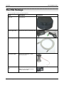
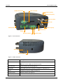
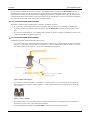
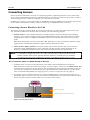
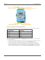
CVG Installation Guide May 2012 SerVision CVG Installation Guide Trademarks & Copyright Trademarks All trademarks mentioned in this manual are the sole property of their respective manufacturers. Copyright SerVision Ltd., Jerusalem, Israel www.servision.net • [email protected] © 2012 SerVision Ltd. All rights reserved. Notice Information in this document is subject to change without notice. SerVision Ltd. assumes no responsibility for any errors that may appear in this manual. Companies, names and data used in examples herein are fictitious unless otherwise noted. No part of this document may be copied or reproduced in any form, or by any means, electronic or mechanical, for any purpose, without the express written permission of SerVision Ltd. SerVision Ltd. makes no warranties with respect to this documentation and disclaims any implied warranties of merchantability or fitness for a particular purpose. 1 SerVision CVG Installation Guide Table of Contents Introduction 3 The CVG Package 4 Additional Equipment 5 Installing the CVG System 6 Selecting a Location for the Unit 6 Diagrams of Connectors 6 Supplying Power to Devices Connected to the Unit 8 Connecting Devices to the CVG Connecting Cameras Connecting a PTZ Controller Connecting Sensors Connecting a Sensor Directly to the Unit Connecting Sensors Using an ADAM Module 9 9 9 11 11 12 Connecting Activators 15 Connecting Sensors and Activators Using an IA Relay Board 16 Connecting a Microphone 17 Connecting a Speaker or Headphones 18 Connecting a CCTV Monitor 18 Connecting a Switch Connecting Multiple Monitors 19 20 Connecting the CVG to a Network 21 Connecting the CVG to a Power Source 22 Appendix: Removing the Micro SD Card 23 Removing the Micro SD Card from the Unit 23 Inserting a Micro SD Card into the Unit 23 2 SerVision CVG Installation Guide Introduction This guide explains how to set up the hardware components of SerVision’s standard CVG security system. The standard CVG belongs to SerVision’s line of embedded Video Gateway units. These units provide state-of-the-art security functionality, including live video streaming, video recording and playback, motion detection, sensor management, real-time event notification, and device activation. All of these features can be accessed remotely via PC, PDA, or cellular telephone. The standard CVG is a basic unit that is optimized for deployment in buildings in which high-speed internet access is available through a cable-based local network (LAN). Once the CVG has been installed as explained in this guide, it must be configured. Configuration is performed by connecting to the CVG unit using a PC that is on the same network as the unit (or connected to the unit directly using a LAN cross cable) and opening the unit’s configuration utility in a browser. For additional information about configuring your CVG, please refer to the Embedded Video Gateway System Guide. Client software is used for accessing the CVG unit remotely in order to view video and events and control the system in various ways. SerVision offers client software for PCs and for certain cellular telephone and PDA models. Full instructions for the use of the client applications are available in separate manuals, which can be downloaded at http://www.servision.net. Introduction 3 SerVision CVG Installation Guide The CVG Package The CVG package contains the following items: Item Description CVG unit Video gateway Power supply cable Connects the unit to an electrical outlet Ethernet (LAN) cable Connects the unit to a local network RS232/485 adapter Connects PTZ controllers or other devices to the unit Micro SD memory card Stores recorded video and other data The CVG Package Illustration Note: The unit is supplied with the memory card in its slot. 4 SerVision CVG Installation Guide Additional Equipment One or two video cameras should be connected to the CVG. You must acquire the cameras you require; they are not included in the CVG package. For information about camera compatibility and about connecting the cameras to the unit, see Connecting Cameras, page 9, or consult your vendor. In addition to the cameras, you may wish to connect some or all of the optional equipment listed below to the CVG unit. For additional information about these items and the cables required to connect them, please refer to the installation instructions for each type of device. NOTE: This equipment is not included in the CVG package. Dry-contact sensor, toggle (on-off) switch to change the active outline (see Connecting Sensors, page 11), or push-button switch to change the display in a connected CCTV monitor (see Connecting a Switch, page 19) Note: A dry-contact sensor or switch can be connected directly to the Sensor connector on the CVG unit. If you use either an ADAM module or an IA relay board, as described below, you can connect an additional 16 dry-contact sensors via the unit’s RS232/485 connector. Note: If you connect a touchscreen monitor to the CVG, you cannot also connect an ADAM module or an IA relay board. In this case, you can only connect one dry-contact sensor to the unit. ADAM Data Acquisition Module and ADAM isolated RS232->RS422/RS485 converter, for connecting up to 16 dry-contact sensors (see Connecting Sensors, page 11) Intelligent Appliance IA-3126-2 relay board, for connecting up to 16 dry-contact sensors (see Connecting Sensors and Activators Using an IA Relay Board, page 16) and 16 activators to the CVG unit Dry-contact activator (an alarm or other device that is turned on or off in response to the activation of a sensor; see Connecting Activators, page 15) Note: An activator can be connected directly to the CVG unit. If you use an IA relay board, as described above, you can connect an additional 16 activators via the unit’s RS232/485 connector. Note: If you connect a touchscreen monitor to the CVG, you cannot also connect an IA relay board. In this case, you can only connect one activator to the unit. Microphone (see Connecting a Microphone, page 17) Speaker or headphones (the unit already contains a built-in speaker; for additional information, please refer to the Embedded Video Gateway System Guide) CCTV monitor for closed-circuit video display (see Connecting a CCTV Monitor, page 18) Additional micro SD cards (see Appendix: Removing the Micro SD Card, page 23) Additional Equipment 5 SerVision CVG Installation Guide Installing the CVG System These are the steps that you will typically follow in order to install the CVG system: 1. Place the CVG unit in its desired location; see Selecting a Location for the Unit, page 6. 2. Install the video cameras in their desired locations. 3. Install a CCTV monitor in its desired location (optional). 4. Install either a dry sensor, a toggle switch (for outline switching), or a push-button switch (for changing the display on a connected CCTV monitor) in its desired location (optional); see Connecting Sensors, page 11. 5. Install an alarm or other activator in its desired location (optional); see Connecting Activators, page 15. 6. If you are using either an ADAM module to connect additional sensors to the CVG, install the sensors in their desired locations (optional); see Connecting Sensors, page 11. 7. If you are using an IA relay board to connect additional sensors or activators to the CVG, install them in their desired locations (optional); see Connecting Sensors and Activators Using an IA Relay Board, page 16. 8. Connect the cameras and other devices to the CVG and to a power supply, as required; see Connecting Devices to the CVG, page 9. 9. Connect the CVG unit to a LAN; see Connecting the CVG to a Network, page 21. 10. Connect the CVG unit to a power source; see Connecting the CVG to a Power Source, page 22. Selecting a Location for the Unit The CVG unit should be placed on a flat surface such as a table or shelf. (It is not designed for mounting directly on a wall.) Ensure the unit has at least a few centimeters (1–2 inches) of space above it and on all sides for ventilation. When choosing a location for the CVG, bear in mind that the unit must be connected to a power source and a LAN or a PC, and that other devices (camera, sensor, etc.) must be connected to it. Choose a location in which these connections are feasible. Diagrams of Connectors The standard CVG unit contains the following connectors. Installing the CVG System 6 SerVision CVG Installation Guide Micro SD Card 12VDC Power Out Audio In (Ain1) Audio Out (Aout) Video In (Vin2) TV-Out RS232/485 Video In (Vin1) Ethernet Out Power Activator (Out1) Sensor (In1) Figure 1: CVG connectors Audio Out Audio In (Ain1) Figure 2: Audio connectors Connector Description 12VDC Power Out Supplies power to external devices, such as cameras and sensors (see page 8) Note: The unit can supply up to 250 mA of power. Micro SD Card Slot for the micro SD card (see page 23) RS232/485 Serial (COM) port for PTZ controllers (see page 9) or technicians' use Power Connector for the power supply (see page 22) Activator (Out1) Activator connector (see page 15) Sensor (In1) Sensor connector (see page 11) Installing the CVG System 7 SerVision CVG Installation Guide Connector Description Ethernet Out 10/100 Base-T LAN connector for connecting the unit to an external network (LAN or WAN; see page 21) TV Out Connector for a CCTV monitor (see page 18) Video In (Vin1 and Vin2) Connectors for video cameras (see page 9) Audio Out (Aout) Connector for an external speaker or headphones (see page 18) Audio In (Ain1) Connector for a microphone (see page 17) Supplying Power to Devices Connected to the Unit The CVG can supply power directly to cameras and other devices via the 12VDC Power Out connector on the rear panel of the unit. However, only a limited amount of power can be supplied by the CVG in this way. If the devices connected to the 12VDC Power Out connector draw too much power, the unit may overheat or otherwise malfunction. Therefore, it is best to provide independent power supplies for devices connected to the unit whenever possible by connecting them directly to a wall outlet. The unit can supply a maximum of 250 mA (3W at 12V) of power through the 12VDC Power Out connector. Typically, this means it can power at most one camera. Nonetheless, you must consult the device documentation to ascertain the actual power usage of each device you want to connect to the CVG unit. For example, if a camera uses 150 mA and a sensor uses 50 mA, the total power usage of the two devices is 200 mA. Since the CVG can supply a maximum of 250 mA, this means that 50 mA are available for other devices when these two devices are connected to the 12VDC Power Out connector on the CVG. NOTE: It is, of course, possible to connect some devices to the 12VDC Power Out connector on the CVG and others directly to a power source – as long as the total power consumption for the devices connected to the 12VDC Power Out connector does not exceed 250 mA. Installing the CVG System 8 SerVision CVG Installation Guide Connecting Devices to the CVG This section explains how to connect devices such as a camera or a sensor to the CVG unit. Connecting Cameras Up to two cameras can be connected to the CVG. If the cameras have PTZ controls for remote aiming and zooming, and the PTZ protocol they use is supported, the control cables can also be connected to the unit. Any PAL or NTSC video camera with a composite video output can be connected to the unit. A cable with a composite video connector on one end, and a male BNC connector on the other, should be used to connect each camera to the CVG. NOTE: A cable with a male RCA connector can be connected to a female BNC connector by using an RCAto-BNC adaptor. Figure 3: RCA-to-BNC adaptor Cameras that are connected to the CVG can receive their power from the CVG unit through the 12VDC Power Out connector on the rear panel of the unit. However, bear in mind that the unit can supply a maximum of 250 mA (3W) of power through this connector. Typically, this is only enough power for one camera. If the devices connected to the unit require more than this amount of power, you must power some or all of them independently by connecting them directly to a power source, as explained under Supplying Power to Devices Connected to the Unit, page 8. To connect a camera: 1. Install the camera in its desired location. 2. Connect the output of the camera to one of the Video In connectors on the unit. 3. Connect the camera's power connector to a power source. Connecting a PTZ Controller If a camera has remote PTZ control features (pan, tilt, zoom, and/or focus), and uses a supported PTZ protocol, you can connect the control cable to the unit. Both RS232 and RS485 PTZ connection types are supported. Consult the camera documentation for information about which connection type to use. NOTE: If you are connecting sensors to the unit using an ADAM module or you are using the RS232/485 connector to connect a touchscreen CCTV monitor to the unit, you cannot connect any RS232 PTZ controllers. For additional information, see Connecting Sensors Using an ADAM Module, page 12; Connecting a CCTV Monitor, page 18. If you want to connect the PTZ controllers of two cameras to the unit, only one of the controllers can use an RS232 connector – the other must use an RS485 connector. PTZ controllers for more than one RS232 camera cannot be connected to the unit simultaneously. Connecting Devices to the CVG 9 SerVision CVG Installation Guide If you connect two RS485 PTZ camera controllers, they should be daisy-chained to the RS232/485 connector, as described below. In this case, each camera in the chain must be given a different ID number. Please refer to your camera's documentation for information about configuring its ID number. In addition, note that you can only create an RS485 daisy chain if both cameras use the same PTZ protocol. Attempting to connect cameras that use different protocols will prevent both of the cameras from working properly. To connect an RS232 PTZ controller: The RS232 controller cable should end with a female 9-pin RS232 connector. If you are only connecting the RS232 PTZ controller to the unit, and are not connecting any RS485 PTZ controllers, plug the 9-pin RS232 connector directly into the RS232/485 connector on the side panel of the unit. If you are also connecting one or two RS485 PTZ controllers to the unit, plug the 9-pin RS232 connector into the RS232/485 adapter supplied with the unit. To connect an RS485 PTZ controller: Each RS485 controller cable should end with two wires. 1. Use a wire connector to connect the wires to the RS485 connection wires of the adapter. Be sure to match the positive (+) wire of the controller cable to the positive (+ red) wire of the adapter, and the negative (-) wire of the controller cable to the negative (- grey) wire of the adapter (see figure 4). Plug into RS232/485 connector on CVG-M RS485 connection wires RS232 connector Negative (-) wire for RS485 connector (grey) Positive (+) wire for RS485 connector (red) Figure 4: RS232/485 adapter To connect two RS485 controllers to the adapter, insert the positive (+) wires of both of the controllers into one slot in the wire connector, and the negative (-) wires of both of the controllers into the other slot of the wire connector. Figure 5: Wire connector 2. If two PTZ cameras are connected to the unit, configure each camera to use a different ID. For information about how to do this, refer to the camera documentation. 3. Connect the RS232/485 adapter to the RS232/485 connector on the side panel of the unit. Connecting Devices to the CVG 10 SerVision CVG Installation Guide Connecting Sensors Sensors are devices that detect events such as a door being opened or a light being turned on. A dry-contact input sensor can be connected directly to the unit. Alternatively, the sensor connector on the unit can be used to connect a switch to change the active outline or the display on a connected CCTV monitor. In addition, if you wish, you can connect either an ADAM Data Acquisition Module or an IA-3126-2 relay board to the unit. Either of these devices makes it possible to connect up to 16 additional sensors to the unit. Connecting a Sensor Directly to the Unit The unit has one sensor connector (In1). You can use this connector to connect a dry-contact input sensor to the unit. Alternatively, In1 can be used to connect a switch for one of the following purposes: Outline switch: If you are defining more than one outline (alternate sets of recording and event-handling settings), you can connect a toggle (on-off) switch to In1 instead of a sensor. The switch can then be used to change the active outline. For additional information, please refer to the Embedded Video Gateway System Guide. Note: Some alarm panels can also be connected to In1. When they are, they can function as automatic outline toggle switches. For additional information, please consult the alarm panel vendor. CCTV-monitor display controller: If a CCTV monitor will be connected to the unit, you can connect a push-button switch to In1 instead of a sensor. The button can then be used to change the display on the monitor. For additional information, please refer to the Embedded Video Gateway System Guide. NOTE: It is possible to configure the CVG to use a single switch as both an outline switch and a CCTVmonitor controller, but this is not generally advisable, because it is unlikely that you will find it convenient to have the outline switched every time the CCTV display changes, and vice-versa. To connect a sensor or switch directly to the unit: 1. Install the sensor or switch in its desired location in accordance with the manufacturer's instructions. Note: If the sensor requires an external power supply, you may be able to connect it to the 12VDC Power Out connector on the rear panel of the unit. However, bear in mind that the unit can supply a maximum of 250 mA (3W) of power. If the devices connected to the unit require more than this amount of power, you must power some or all of them independently (see Supplying Power to Devices Connected to the Unit, page 8). 2. Connect the two wire contacts of the sensor or switch to the In1 connector on the rear panel of the CVG, as illustrated in figure 6. Insert the wires into the connectors and tighten the screws below each connector to hold the wires in place. It does not matter which wire you connect to each contact. Sensor CVG rear panel Input/Output terminal block Out1 In1 Figure 6: Connecting a sensor Connecting Devices to the CVG 11 SerVision CVG Installation Guide Connecting Sensors Using an ADAM Module If you want to connect additional dry sensors to the CVG, you can do so by connecting an ADAM Data Acquisition Module to the unit. Up to 16 additional dry sensors can then be connected to the unit through the ADAM module. NOTE: Alternatively, you can connect additional sensors using an IA-3126-2 relay board, as explained Connecting Sensors and Activators Using an IA Relay Board, page 16. To connect sensors using an ADAM module, you will need the following items: ADAM-4051 Data Acquisition Module (available from SerVision) ADAM-4520 isolated RS232->RS422/RS485 converter (available from SerVision) Flat ribbon cable with D-type 9-pin female connector on one end and a D-type 9-pin male connector on the other end Wire to connect the ADAM module to the ADAM converter – red, black, yellow, and green Wire and an electrical plug (optional) to connect the ADAM module to a power source (either a power supply from the unit or an independent connection) Figure 7: ADAM-4051 module NOTE: Figure 8: ADAM-4520 isolated converter The instructions below explain how to connect sensors to the CVG using the ADAM module and converter described above. For additional information about connecting and configuring the ADAM module and converter, please refer to the manufacturer's documentation, or contact your vendor. To connect sensors using an ADAM module: 1. Install the sensors in their desired locations in accordance with the manufacturer's instructions. 2. Connect the wire contacts of each of the sensors to the terminal blocks of the ADAM-4051 module as follows: Connect all of the negative (-) wires of all of the sensors to one of the ground (D GND) connectors on the ADAM module. If the wires cannot all be inserted into the connector, use a wire connector to connect them together, and then connect the wire connector to the ground (D GND) connector on the ADAM module. Connect each of the positive (+) sensor wires to one of the numbered connectors (D1 0 through D1 15) in the terminal blocks of the module. Connecting Devices to the CVG 12 SerVision CVG Installation Guide D GND D1 0 through D1 10 Connect sensor ground wires to this connector Connect positive (+) sensor wires to these connectors D GND D1 11 through D1 15 Connect sensor ground wires to this connector Connect positive (+) sensor wires to these connectors Figure 9: Connecting sensors to the ADAM-4051 module 3. Connect the ADAM-4051 module to the ADAM-4520 isolated converter as follows (see figure 11, page 15): Connect this connector on the ADAM-4051 To this connector on the ADAM-4520 (Y) Data+ Data+ (G) Data- Data- (R) +Vs (R)+Vs (B) GND (B)GND 4. Connect the ADAM-4520 isolated converter to the RS232/485 connector on the rear panel of the CVG unit in one of the following ways: If you are not connecting any RS485 PTZ controllers to the unit, using the 9-pin flat ribbon cable, connect the RS232 connector of the ADAM-4520 converter directly into the RS232/485 connector. If you are also connecting one or more RS485 PTZ controllers to the unit, using the 9-pin flat ribbon cable, connect the RS232 connector of the ADAM-4520 converter into the RS232 connector of the RS232/485 adapter supplied with the unit. Connect the PTZ controllers to the adaptor as explained under Connecting a PTZ Controller, page 9. Then plug the adaptor into the RS232/485 connector on the unit. Connecting Devices to the CVG 13 SerVision CVG Installation Guide Plug into RS232/485 connector on MVG RS232 connector Figure 10: RS232/485 adapter Note: If you connect an ADAM module to the unit, you cannot connect any RS232 PTZ controllers, a touchscreen controller, or an IA relay board to the unit. For additional information, see Connecting a PTZ Controller, page 9; Connecting a CCTV Monitor, page 18; Connecting Sensors and Activators Using an IA Relay Board, page 16. 5. Connect the ADAM-4051 module to the power source as follows (see figure 11, page 15): Connect the positive (+) wire of the power supply cable to the (R) +Vs connector on the module Connect the negative (-) wire of the power supply cable to the (B) GND connector on the module Note: Each of the power connectors on the module will then have two wires connected to it – one connecting it to the power supply, and one connecting it to the power connectors of the ADAM-4520 converter. Connecting Devices to the CVG 14 SerVision CVG Installation Guide Note: You may be able to use the CVG to supply power to the modules by connecting the power supply cables to the 12VDC Power Out connector on the rear panel of the unit. However, bear in mind that the unit can supply a maximum of 250 mA (3W) of power. If the devices connected to the unit require more than this amount of power, you must power some or all of them independently (see Supplying Power to Devices Connected to the Unit, page 8). Connect to RS232/485 connector on the MVG (Y) Data + (R) +Vs (B) GND (G) Data Connect to power supply (+) Connect to power supply (-) Figure 11: Connecting the module to the converter, the CVG, and the power supply Connecting Activators Activators are external devices such as alarms and lights that can be turned on by the system in response to an event. Essentially, the unit functions as an on/off switch for the device. The unit activates the activator by closing the circuit of its power supply. One activator can be connected directly to the unit. In addition, if you wish, you can connect an IA-3126-2 relay board to the unit. This makes it possible to connect up to 16 additional activators to the unit (see Connecting Sensors and Activators Using an IA Relay Board, page 16). In addition to the activator itself, you will need 16 AWG red and black cables to connect an activator to the unit. To connect an activator directly to the unit: 1. Install the activator in its desired location in accordance with the manufacturer's instructions. Note: If the activator requires an external power supply, you may be able to connect it to the 12VDC Power Out connector on the rear panel of the unit. However, bear in mind that the unit can supply a maximum of 250 mA of power. If the devices connected to the unit require more than this amount of power, you must power some or all of them independently. For additional information, see Supplying Power to Devices Connected to the Unit, page 8. 2. Connect the two contacts of the activator to the Out1 connector on the CVG, as illustrated in figure 12. It does not matter which wire you connect to each contact. Connecting Devices to the CVG 15 SerVision CVG Installation Guide Activator + Power - CVG rear panel Input/Output terminal block Out1 In1 Figure 12: Connecting an activator that has its own power supply Connecting Sensors and Activators Using an IA Relay Board If you want to connect additional dry sensors and/or one activator to the CVG, you can do so by connecting an Intelligent Appliance IA 3126-2 relay board to the unit. Up to 16 additional dry sensors and 16 additional activators can then be connected to the unit through the relay board. Sensor and activator events from devices connected to an IA relay board can be seen in SerVision client applications and activators can be turned on and off via these applications. However, the sensors and activators cannot be configured using the CVG’s configuration utility. NOTE: Alternatively, you can connect additional sensors using an ADAM module, as explained under Connecting Sensors Using an ADAM Module, page 12. Sensors that are connected through an ADAM module can be configured using the CVG’s configuration utility. Figure 13: IA 3126-2 relay board For information about connecting sensors and activators to the IA 3126-2 relay board, and about connecting the relay board to a power source, please consult the relay-board’s documentation. Connecting Devices to the CVG 16 SerVision CVG Installation Guide NOTE: If you are connecting less than 16 activators or 16 sensors to the relay board, be sure to connect them to the relay beginning with the lowest connector, and do not leave open connectors between those that you use. For example, if you are connecting 4 activators and 3 sensors, connect the activators to output connectors 1-4 on the board and the sensors to input connectors 1-3 on the board. To connect the IA 3126-2 relay board to the CVG: 1. Set the ID of the relay board to 0. (For information about how to do this, consult the relay-board documentation.) 2. Connect the relay board to the RS232/485 connector on the rear panel of the CVG unit in one of the following ways: If you are not connecting any RS485 PTZ controllers to the unit, using a 9-pin flat ribbon cable, connect the RS232 connector of the relay board directly into the RS232/485 connector. If you are also connecting one or more RS485 PTZ controllers to the unit, using a 9-pin flat ribbon cable, connect the RS232 connector of the relay board into the RS232 connector of the RS232/485 adapter supplied with the unit. Connect the PTZ controllers to the adaptor as explained under Connecting a PTZ Controller, page 9. Then plug the adaptor into the RS232/485 connector on the unit. Plug into RS232/485 serial port connector on HVG RS232 connector Figure 14: RS232/485 adapter Note: If you connect a relay board to the unit, you cannot connect any RS232 PTZ controllers or an ADAM module to the unit. For additional information about connecting PTZ controllers to the unit, see Connecting a PTZ Controller, page 9. For information about connecting an ADAM module to the unit, see Connecting Sensors Using an ADAM Module, page 12. Connecting a Microphone A microphone can be connected to the unit. When one is connected, you can hear and record sound along with video images. Either a passive microphone, which requires external amplification, or an active (self-amplifying) microphone, can be used. Microphones with an output voltage of 1 Vrms or 1.41 Peak are supported. To connect a microphone: 1. Install the microphone in the desired location. 2. Plug the microphone connector into the Audio In (Ain1) connector on the side of the unit. Connecting Devices to the CVG 17 SerVision CVG Installation Guide Connecting a Speaker or Headphones The CVG unit contains a built-in, 1-watt, internal speaker, which is located on top of the unit. You can also connect an external speaker or headphones to the unit. The speakers (and headphones) allow you to hear audio that is transmitted from client applications. The external speaker or headphones can be used in addition to the internal speaker or instead of it. (For additional information, please refer to the Embedded Video Gateway System Guide.) Internal speaker Audio Out Figure 15: Internal speaker and Audio Out connector To connect a speaker or headphones: 1. Install the speaker in its desired location, if necessary. 2. Plug the speaker or headphone connector into the Audio Out (Aout) connector on the side of the unit. 3. If the speaker requires an independent power supply, connect its power supply cable to a power source. Connecting a CCTV Monitor A CCTV monitor can be connected to the CVG unit. The monitor offers an alternative way to view live video from the CVG. It is primarily useful if you want to view video when the user is near the unit. For example, if the CVG is set up in a grocery store, and you sit at the check-out counter, you can use a CCTV monitor to keep tabs on parts of the store that you cannot see from your seat. The following types of monitors can be used: Surveillance monitors: Monitors that are designed to be plugged directly into surveillance cameras. Entertainment monitors: Monitors that are intended to be plugged into portable DVD players in vehicles. Standard television sets with AV connectors When choosing a monitor to connect to the unit, ensure the monitor supports the video format used by the cameras (NTSC or PAL). Some SECAM monitors will also work when the PAL video format is used. If you choose a monitor with touchscreen support, you can use the monitor to view recorded video as well as live video. For information about recommended types of touchscreen monitors, please consult your vendor. NOTE: If you are connecting an RS232 PTZ controller to the unit, you cannot use touchscreen functionality because the RS232 serial port is not available. For additional information, see Connecting a PTZ Controller, page 9. To connect the monitor to the CVG, you will need a cable with the following connectors: Connecting Devices to the CVG 18 SerVision CVG Installation Guide An appropriate connector (BNC or RCA) for the Video In connector of the monitor. (Consult the monitor documentation or your vendor to find out which kind of connector is required for the particular monitor you are using.) A BNC male connector to connect to the TV Out connector of the CVG. (A cable with an RCA connector can be used by attaching a BNC-to-RCA adaptor to the connector. See figure 7, page 9.) To connect the output of a touchscreen to the unit, you will need a cable with the following connectors: An appropriate connector to connect to the touch output connector on the monitor A female 9-pin RS232 connector to connect to the CVG’s RS232/485 connector. An appropriate cable should be supplied with the monitor. To connect a CCTV monitor: 1. Install the monitor in its desired location. 2. Connect the Video In connector of the monitor to the TV Out connector of the CVG, using a cable with an appropriate connector (BNC or RCA) for the Video In connector of the monitor on one end, and a BNC male connector on the other end. Note: If you are using a standard television set as a monitor, use the television’s AV connector as the Video Input connector. 3. If the monitor is touch-sensitive, connect the touch output to the RS232/485 connector as follows: If you are not connecting any RS485 PTZ controllers to the unit, connect the RS232 connector of the touch output cable directly into the RS232/485 connector. If you are also connecting one or more RS485 PTZ controllers to the unit, connect the RS232 connector of the touch output cable to the RS232 connector of the RS232/485 adapter supplied with the unit (see figure 16 below). Connect the PTZ controllers to the adaptor as explained under Connecting a PTZ Controller, page 9. Then plug the adaptor into the RS232/485 connector on the unit. Plug into RS232/485 connector on CVG-M RS232 connector Figure 16: RS232/485 adapter 4. If the monitor is touch-sensitive, it is recommended that you calibrate it before you use it. For information about how to calibrate the monitor, please refer to the monitor’s documentation. Connecting a Switch If you wish, you can connect a switch to the unit to change the display on the monitor. The switch must be connected to the In1 connector. For additional information, see Connecting Sensors, page 11, and refer to the Embedded Video Gateway System Guide. Connecting Devices to the CVG 19 SerVision CVG Installation Guide Connecting Multiple Monitors If you wish, you can connect multiple CCTV monitors to the CVG. For example, you may wish to have one monitor beside the driver’s seat and another beside the conductor’s seat. To connect multiple monitors, you must use video splitters to split the connection. Bear in mind, however, that the image quality in each of the monitors will be slightly degraded. To correct this problem, you can use a video amplifier (booster) for each monitor. To ensure you have the correct equipment, consult a video equipment supplier. Connecting Devices to the CVG 20 SerVision CVG Installation Guide Connecting the CVG to a Network The standard CVG should be connected to a local network using a network cable. Once connected, it can be accessed either from a PC on the same LAN network or via the internet through the LAN’s gateway (router). To connect the CVG unit to a LAN: Connect the Ethernet Out connector on the CVG unit to a LAN connection point (a hub, wall socket, or any other connection point) using the supplied Ethernet cable (see The CVG Package, page 4). Connecting the CVG to a Network 21 SerVision CVG Installation Guide Connecting the CVG to a Power Source The standard CVG must be connected to an electrical outlet using the supplied power-supply cable. Once it is connected, the unit starts up automatically. During the start-up process, the Power LED on the top of the unit flashes at various intervals. When the start-up process is completed successfully, the Power LED should display as a solid color and blink momentarily every second. (Depending on the configuration settings, it should either be solid orange and then blink green or solid green and then blink orange.) Power LED Figure 17: Power LED NOTE: When the start-up process is completed, if the Power LED does not flash – it displays as a solid green or orange all the time – the start-up process was not successful. In this case, disconnect the unit from the power supply and then reconnect it. WARNING: Only the power supply cable that came with the unit should be used. Use of a power supply other then the one provided in the package may cause irreparable damage to the unit. In particular, do not use the power supply cable from an HVG 200 unit, because it will not supply sufficient power to the unit. Furthermore, and most important, never use the CVG power supply cable with an HVG 200, because this will ruin the HVG 200. To connect the standard CVG to a power source: Connect the Power connector on the rear of the CVG unit to a standard wall socket using the supplied power supply cable (see The CVG Package, page 4). The unit starts up. Connecting the CVG to a Power Source 22 SerVision CVG Installation Guide Appendix: Removing the Micro SD Card The CVG unit stores all recorded video and event information on a standard micro SD card. The unit is supplied with a 4 GB micro SD card. You can remove this card from the unit in order to copy video files from it and/or replace it with a different micro SD card. NOTE: The CVG cannot record video or event information unless an appropriate micro SD card is in the card slot. NOTE: SerVision provides a software application for downloading recorded video and other data from a micro SD card. The software can be downloaded from the SerVision website (http://www.servision.net). Once the data is downloaded, you can view it in the MultiClient. For additional information, please contact SerVision technical support. Removing the Micro SD Card from the Unit You can remove the micro SD card from the CVG unit. To remove the micro SD card: 1. Press the edge of the card that protrudes slightly from the card slot. The card pops partway out of the slot. Press here Figure 18: Removing the micro SD card 2. Pull the card out of the slot. Inserting a Micro SD Card into the Unit You can reinsert the supplied micro SD card or a different micro SD card into the CVG unit. Appendix: Removing the Micro SD Card 23 SerVision CVG Installation Guide To insert a micro SD card into the unit: Hold the card as illustrated below and push it gently into the card slot until it clicks into place. Hold the card on this edge, with the lettering facing up. Figure 19: Micro SD card Appendix: Removing the Micro SD Card 24 POB 45205 Jerusalem 91450 Israel Tel: +972-2-535 0000 • Fax: +972-2-586 8683 www.servision.net • [email protected] CVG Installation Guide