1
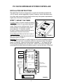
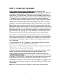
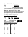
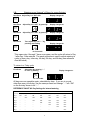
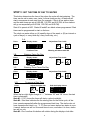
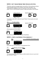
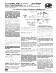
RAIN CLOCK
OWNERS MANUAL
SPRINKLER SYSTEM CONTROLLER
RAIN CLOCK MODELS
PC-104
PC-106
4 Station
6 Station
PC-104-PS
4 Station with Pump Relay
Circuit
PC-106-PS
6 Station with Pump Relay
Circuit
Rain Bird Sales, Inc.
Customer Support Center
6991 E. Southpoint Rd., Bldg. #1, Tucson, AZ 85706
1
PC-104/106 SPRINKLER SYSTEM CONTROLLER
INSTALLATION INSTRUCTIONS
Rain Bird Rain Clocks are designed for use with all standard residential 24
volt AC electric valves regardless of brand. However, some older brass electric valves and commercial duty plastic valves may have power requirements
higher than this series is designed for
STEP 1: MOUNT THE TIMER
Location: Select a location inside a building,
and within six feet of a grounded electrical
outlet. This is not an outdoor timer. Do not
mount it where it is exposed to any of natures elements. If it must be outside,
be sure to use an outdoor enclosure and a
weatherproof electrical connection.
Lift
Cover Removal: Remove the front cover of
the timer by depressing the bottom tab and
lifting as shown in Figure 1.
FIGURE 1
Press Here
Mounting: Mount the timer to a wall using two #10 screws installed at centers
13
3 /16" apart at eye level. Use plastic anchors to secure screws if the wall is
plastic or masonry. Leave the screw heads extended ¼ " and hang the Rain
Clock using the keyhole slots on the back. Install a third screw through the
mounting hole (located below the battery area) to secure the timer to the wall.
Mounting Holes
FUSE
1
/2A 250V 3AG
OR
YELLOW
1
RED
2
FUSE
3
/4A 250V 3AG
BLUE
3
Station
Output
Terminals
AS INDICATED
ON THE UNIT
Plug Transformer
into 120 volt AC
electrical outlet
4
5
6
ONLY ON SIX
STATION MODELS
Key Pad
MV
ONLY ON PUMP START
MASTER VALVE MODELS
9 Volt Battery
Mounting Hole
To
Control
Valves
!
ATTENTION
Battery must be installed
to ensure proper operation.
2
FIGURE 2
STEP 2: CONNECTING THE WIRING
How to choose the right type of sprinkler wire: Use 18-gauge “bell,”
“thermostat” or “underground burial” wire for the sprinkling system. “Bell wire”
is available in single strands or twisted in 2 or 3 wire sets and can only be
used indoors. “Thermostat wire,” the most common sprinkling system wire, is
typically available with up to 7 wires twisted inside a brown PVC jacket (about
¼” in diameter), and is suitable for most indoor and conduit installations.
“Direct Burial” cable is similar to thermostat wire, except the jacket is made of
a black Poly UV resistant material, and is suitable for any indoor or outdoor
installation, including sunlight exposure. Each individual wire is color-coded.
Note: Some areas require by code the use of UL approved cable only. Most
Direct Burial Cables have this approval. Most thermostat and bell wires do not.
Important: 18 gauge wire or /larger is recommended for sprinkler system wire,
allowing cable to be run up to 600’ without problems. Some thermostat wire
that is referred to as “sprinkler wire” may actually be a smaller gauge (#19 or
#20) and will not have the UL listing or the capacity to run long distances.
The number of wires needed is determined by the number of valves being
wired, plus a common wire. For example, three valves in a grouping require a
4-wire cable since the 4th wire serves as the common wire. If a system had
two valves in the front yard, and four in the back, the wiring could be run in
one of two ways:
1) Use a single run or 18/7 (18 gauge, 7 wires) cable connected ‘in-series’
from the front valves to the back valves to the timer;
2) Use one run of 18/3 cable from the timer to the front valves, and one run of
18/5 cable from the timer to the back valves.
All wiring connections should be sealed with a water-tight connector. Cables
that are run indoors should be properly secured with a staple or clip.
How to connect the valves: Each valve connects to the timer through two
wires. One wire from each valve solenoid must connect to the output terminal
of the timer. This is the “HOT” connection. The second wire of each solenoid
must connect to the (COM.) common terminal of the timer. This is the
“COMMON” connection. If the valves are grouped together, it is easier to join
the common from all valves and just run one wire to the timer’s (COM.) common terminal.
Note: Only one valve may be connected to each station output terminal.
3
STEP 3: CONNECTING THE TRANSFORMER
Refer to Figure 2 and connect the yellow wire to the terminal marked
"YELLOW," and red wire to the terminal marked "RED" and the blue wire to the
terminal marked "BLUE." Caution: Always connect the wires before plugging in
the transformer. If not, you run a risk of short circuiting the transformer and/or
clock.
STEP 4: USING THE PUMP START CIRCUIT
Pump start or master valve capability is available only on the PC-106-PS and
PC-104-PS models. This circuit allows the timer to be used in conjunction with
a "pump relay switch" (Rain Bird model PCR-1) which when activated by the
timer, will in turn activate the pump. The pump start circuit can also be used to
operate a standard 24-volt "master valve."
The hot wire of the relay switch connects to the terminal marked "MV" The common wire connects to the regular system common wire or terminal. See the
pump relay’s instruction booklet for details.
Caution: Be sure the total current draw of the relay switch plus the station valve
doesn't exceed 650 milliamps.
Important: To avoid pump damage caused during a "default schedule," wire
each unused station terminal to a terminal that is being used. This prevents the
pump from operating against closed valves if the default program kicks-in during
a power failure.
STEP 5: INSTALL A BATTERY
To ensure proper timer operation, install a 9-volt alkaline battery (not included)
to the snap connector near the bottom edge of the control panel. In the event of
a power failure the battery will maintain the programmed watering schedule in
memory for up to 24 hours.
The battery will not allow the timer to open any valves, but the timer will remember the approximate time of the power failure. When the power resumes, an uncompleted watering cycle will be completed. If a watering start was missed during the outage, it will be initiated once the power resumes. After a power outage, reset the exact time of day.
If the battery is dead or doesn't have enough power left, none of the programming will be retained. In this event, the timer will revert to its "default program,"
which waters once per day, 10 minutes per station, 8 hours after the power is
restored. All programming steps must be repeated.
4
PROGRAMMING INSTRUCTIONS
Use to set the
days to water
Use to set the
daily start times
Use to set
current time
Adjust time up
and days to on
Use to set
length of
watering
SET
CLOCK
WATER
DAYS
STATION
TIMING
MANUAL
START &
WATER
TIMES
PER DAY
AUTO
ADVANCE
ON
Adjust time
down and days
to off
OFF
OFF
Use to operate
system manually
Use to put timer
in rain shut down mode
STEP 1: SET THE CURRENT TIME AND DAY
SET
CLOCK
The PC-104/106 Series holds a 7 day program which repeats after the
seventh day. The days of the week relate to a number as follows.
Actual Days >>>
Sun
Mon
Tue
Wed
Thu
Fri
Sat
Day Number>>>
1
2
3
4
5
6
7
This timer displays in military time. To convert from AM/PM time to military time,
see the reference chart on the next page.
1-A:
Enter Today’s Day Number
Press
Adjust day setting with:
Display Shows:
OFF
SET
CLOCK
ON
OR
Day
Tues.
Setting “:d 3”
Example:
To set Tuesday = Day 3
1-B:
Enter the Current Hour in Military Time
First Press
Adjust the hour with:
Display Shows:
OFF
SET
CLOCK
ON
OR
Hour
Example:
2:00 PM = 1400 Hrs
1-C:
Enter the Current Minute
First Press
Adjust the minutes with:
2:00 pm
Setting “:h 14”
Display Shows:
OFF
SET
CLOCK
ON
OR
Hour
Example:
20 minutes past the hour
Setting “:n
5
20”
1-D:
To display the Current Time
Press
Display Shows:
SET
CLOCK
The above setting of 2:20 PM = 1420 military time
You can also press the “SET CLOCK” button during any other programming
operation to return it to the time of day display.
STEP 2: SET THE DAYS OF THE WEEK TO WATER
When shipped from the factory, the PC-104/106 Series is pre-set to water every
day of the week. Since this is a single program timer, all stations will water on
the same program of watering days.
The clock can water either on (A) specific days of the week, or (B) an interval or
cycle of days (i.e. every third day, every fourth day, etc.).
2-A:
Press
Watering on specific days of the week
Then turn on/off with:
Display Should be:
OFF
SET
CLOCK
ON
OR
Day
Example:
If Monday should be off, display
Repeat this process for each day of the week
REFERENCE CHART #1: Military Time Conversion Table
Normal
Military
Normal
Military
12:00 Midnight
0000
12:00 Noon
1200
1:00 AM
0100
1:00 PM
1300
2:00
0200
2:00
1400
3:00
0300
3:00
1500
4:00
0400
4:00
1600
5:00
0500
5:00
1700
6:00
0600
6:00
1800
7:00
0700
7:00
1900
8:00
0800
8:00
2000
9:00
0900
9:00
2100
10:00
1000
10:00
2200
11:00
1100
11:00
2300
6
2-B:
Watering on an “Interval” of Days (i.e. every 3rd day)
Now Press Adjust Day 1 to “ON” with:
WATER
DAYS
Display changes to:
ON
Now Press
Adjust Day 2 to “OFF” by pressing:
Display changes to:
OFF
WATER
DAYS
Now Press
Adjust Day 3 to “OFF” by pressing:
Display changes to:
OFF
WATER
DAYS
Now Press
Then adjust Day 4 to “- -” by
pressing and holding
Display changes to:
OFF
WATER
DAYS
for 3 seconds.
This means day 4 through 7 have no program, and the cycle will return to Day
1 after Day 3 has watered. The same procedure is used to adjust watering in
cycles of every day, other day, 4th day, 5th day, and 6th day (see reference
chart #2 below).
To return to a 7-day cycle
First Press
Adjust the day showing “- -”
to “ON” by holding
WATER
DAYS
Display changes to:
ON
for 2 seconds.
All days are now operable again, selectable by days. If you are in a cycle
other than every fourth day, use the same process and change “- -” into “ON”
on the first day shown to be “- -”.
REFERENCE CHART #2: Day Settings for interval watering
Desired Watering Cycle
Day Number
Every Day
Every Other Day
Every Third Day
Every Fourth Day
Every Fifth Day
Every Sixth Day
Every Seventh Day
Day 1
ON
ON
ON
ON
ON
ON
ON
Day 2
--
OFF
OFF
OFF
OFF
OFF
OFF
Day 3
--
--
OFF
OFF
OFF
OFF
OFF
Day 4
--
--
--
OFF
OFF
OFF
OFF
Day 5
--
--
--
--
OFF
OFF
OFF
Day 6
--
--
--
--
--
OFF
OFF
Day 7
--
--
--
--
--
--
OFF
7
STEP 3: SET THE TIME OF DAY TO WATER
This button determines the time of day when the cycle will start watering. The
timer can be set to water once, twice, or three times per day. All stations will
start in sequence at each start time (for example, if this is a four station timer,
and the start times are set at 8:00 AM, 1:00 PM, and 6:00 PM, all four stations
will go on sequentially at 8:00 AM, 1:00 PM, and 6:00 PM).
Start #1 is preset at 8:00. Starts #2 and #3 are blank unless programmed. Start
times can be programmed to start on the hour.
The clock can water either on (A) specific days of the week, or (B) an interval or
cycle of days (i.e. every third day, every fourth day, etc.).
3-A:
Press
Display shows:
Adjust Start Time 1 with:
OFF
WATER
TIMES
PER DAY
ON
First Start Time
3-B:
Press
OR
Watering will start at 8:00 AM
Watering Twice Per Day
Display shows:
Adjust Start Time 2 with:
OFF
WATER
TIMES
PER DAY
ON
OR
i.e. 6:00 PM
3-C:
Press
Watering Three Times Per Day
Display shows:
Adjust Start Time 3 with:
OFF
WATER
TIMES
PER DAY
ON
OR
i.e. 6:00 PM
3-D:
Press
WATER
TIMES
PER DAY
To remove a Start Time
Adjust the digits with:
Until the display shows:
OFF
ON
OR
When the two right digits change to “- -” between “23” and “00” hours, the start
time is eliminated.
Note #1: If “00” shows the timer will start a cycle at midnight.
Note #2: Start time indicates the the starting time for the entire cycle, all stations operate sequentially after the programmed start time. The stations do not
have separate start times; e.g., “2 12” does not mean station two starts at noonit means station one will run a second time at noon, and when it is done, station
two will run, etc.
Note #3: Don’t confuse this button with station timing-the displays look alike.
8
STEP 4: SET THE WATERING TIME FOR EACH STATION
This button sets how long each station (zone) will run. Each station can be separately adjusted between 0-99 minutes in one minute increments. This
“watering time” is always the same for that station, every time the system
waters. The PC-106/106 series is preset to water each station for ten minutes.
Press
Display will show:
Adjust the time using:
OFF
STATION
TIMING
ON
OR
Station 1 10 min-
To repeat for station #2 to station #6, push “Station Timing” again and repeat
adjustments.
4-B:
To skip a station
Press
Display will show:
Adjust the time to 00:
OFF
STATION
TIMING
ON
OR
Station 2 0 minutes
After programming the last station,
Press
Display will show:
STATION
TIMING
Press “Set Clock” to return to the normal time of day display.
STEP 5: START A WATERING CYCLE MANUALLY
To start an entire watering cycle
5-A:
Press
The display will show:
MANUAL
START &
ADVANCE
Station 1 Blink
Each station will run sequentially for its programmed time.
5-B:
Press
To advance to the next station
The display will show:
MANUAL
START &
ADVANCE
Station 2 Runtime
The clock will stop the manual operation after last station has run or you touch
the “AUTO/OFF” button.
9
STEP 6: TO INTERRUPT WATERING FOR RAIN
The “AUTO/OFF” button allows the watering and programming to be interrupted
until pressed again. it does not affect the program, but it does prevent power
from going to the valves.
Press
Display will show: The Current Time
AUTO
OFF
Last Digit Blinks
i.e. the current time is 8:00 a.m.
Press “AUTO/OFF” again to return to normal.
TROUBLE-SHOOTING
Sometimes when problems occur they can be easily solved by rechecking some
often overlooked possibilities. So check here before you call your dealer or
contractor. It could save you time and money
IF YOU'RE HAVING THIS PROBLEM:
CHECK FOR THESE THINGS:
Automatic Cycle doesn't turn on and the Manual
Start won’t operate:
-If the display is blank, check the fuse.
-Check the wire connections for improper
wiring or shorts.
-Check the valve and valve solenoid for
proper operation.
-If the last digit blinks, the timer is in the
Rain Shutoff Mode. Press 'Auto/Off" for
normal operation.
-Check the wiring for a short or a crossconnection.
-This is probably not a timer problem, but
a valve problem. Check the solenoid and
the inside of the valve for obstructions.
-Check the fuse and transformer
-Circuit problem/replace timer
-9 volt battery needs replacing and the
timer needs reprogramming.
-Timer is in Rain Shutdown Mode. Press
"Auto/Off" for normal operation.
-Timer is counting down time remaining on
the station currently watering.
-Caused by intermittent power fluctuations.
Nothing can be done except to correct
time.
-There is a short in the wire between the
timer and valve. Make sure connections
are watertight and no bare wires are exposed.
-Maximum current is being exceeded.
Check amperage draw of solenoid
(especially older models and brass
valves). On pump start models, check
combined amperage draw of pump relay
and valve.
Automatic Cycle doesn't operate but the Manual
Start does:
Automatic Cycle doesn't turn off:
Entire Display is blank:
Some of the display won’t appear:
Entire Display blinks:
Last Digit blinks:
Last Two Digits blink:
Timer gains/loses a few minutes/week:
Fuse Blows too often/display goes blank:
10
Programming limitations of this timer
The PC-104/106 series are very flexible timers available at a very economical
price. However, there are some things it will not do:
-It will not run more than one valve per station (i.e. two valves can't be connected to one terminal/station);
-It will not run some stations on one set of days and some stations on another set of days. This
feature is called dual programmability.
-It will not run stations on separate start times. All stations will start on the same schedule.
-It is not designed for outdoor installation.
-It is not in a waterproof case, and will therefore be adversely affected by the climate, nor is it
electrically prudent to plug the transformer in an exterior outlet.
If you need any or all of these features, Rain Bird manufactures a variety of additional models incorporating these and other features. Please contact your
dealer for details.
GENERAL INFORMATION
What happens during a power failure?
In the event of a power failure, the emergency battery back-up will maintain the
watering program in memory for up to 24 hours. However, the battery will not
operate the valves. If the power is off for longer than the battery will last, the
entire program is lost and the entire display will blink after power is restored.
The timer is now operating in the default mode: eight hours after the power
came back on, each station will water for 10 minutes, every 24 hours. To
change this, just reprogram.
When is the best time to water?
The early morning hours -between 2 and 6 a.m. - are the best hours to water.
There is low evaporation very little wind, and water pressure is usually highest
then. Watering in the middle of the day tends to "scorch" the grass, and watering in the late evening tends to "mildew” the grass before sunrise.
How long should the system water?
During hot weather, most lawns require ½” water every other day, or about an
inch and a half of water per week. Hotter climates require more and cooler climates require less. Sandy soils need frequent and greater amounts because of
excess drainage but clay soil needs lesser, more infrequent amounts to prevent
runoff. New lawns require frequent but short burst of water. See our special
"Watering Tips" brochure at your dealer, or check with your garden center for
local conditions.
Different sprinklers water at different rates. Sprayheads and bubblers water fast
(usually 5-15 minutes will put down ½”), but impulse sprinklers and rotors water
slow (usually 45-90 minutes will put down ½"). To check your watering rates,
place a flat bottom pan and measure the time takes to fill it.
11
What should be done in the winter?
If you live in an area where you don't use the timer for an extended period of
time, we recommend unplugging and possibly storing the timer. The "Auto/Off "
rain shutdown mode is a short-term shutdown only, not a winterization mode. In
addition, if you're in a freezing area, be sure your sprinkler lines don't have any
water left in them.
NOTE: This Rain Clock Timer generates radio frequency energy and may
cause interference to radio and television reception. It has been type tested
and found to comply with the limits for a Class B computing device in accordance with the specifications in Subpart J of Part 15 of FCC Rules, which are
designed to provide reasonable protection against such interference in a residential installation. However, there is no guarantee that interference will not
occur in a particular installation. If this equipment does cause interference to
radio or television reception, which can be determined by turning the equipment off and on, the user is encouraged to try to correct the interference by
one or more of the following measures:
-reorient the receiving antenna
-move the timer away from the receiver
-plug the timer into a different outlet so out timer and receiver are on different
branch circuits.
If necessary, the user should consult the dealer or an experienced radio and
television technician for additional suggestions. The user may find the following
booklet prepared by the Federal Communications Commission helpful: "How To
Identify and Resolve Radio-TV Interference Problems." This booklet is available
from the US Government Printing Office, Washington D.C. 20402,
Stock No. 004-000-0034504. (Price is $2.00 postpaid.)
Rain Bird Sales, Inc.
Customer Support Center
6640 S. Bonney Ave. Tucson, AZ 85706
1-800-RAIN-BIRD (520) 434-6289 FAX
© Rain Bird Sprinkler Mfg. Corp.
12