1
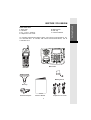
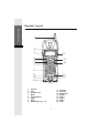
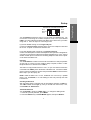
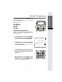
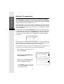
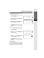
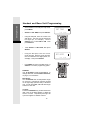
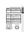
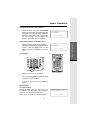
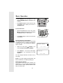
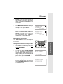
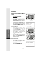
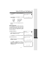
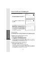
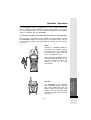
Important Safety Instructions When using your telephone equipment, basic safety precautions should always be followed to reduce the risk of fire, electric shock and injury, including the following: 1. Read and understand all instructions. 2. Follow all warnings and instructions marked on the product. 3. Unplug this product from the wall outlet before cleaning. Do not use liquid cleaners or aerosol cleaners. Use a damp cloth for cleaning. 4. Do not use this product near water (for example, near a bath tub, kitchen sink, or swimming pool). 5. Do not place this product on an unstable cart, stand, or table. The product may fall, causing serious damage to the product. 6. Slots and openings in the cabinet and the back or bottom are provided for ventilation. To protect it from overheating, these openings must not be blocked by placing the product on the bed, sofa, rug, or other similar surface. This product should never be placed near or over a radiator or heat register. This product should not be placed in a built-in-installation where proper ventilation is not provided. 7. This product should be operated only from the type of power source indicated on the marking label. If you are not sure of the type of power supply to your home, consult your dealer or local power company. 8. Do not allow anything to rest on the power cord. Do not locate this product where the cord will be abused by persons walking on it. 9. Never push objects of any kind into this product through cabinet slots as they may touch dangerous voltage points or short out parts that could result in a risk of fire or electric shock. Never spill liquid of any kind on the product. 10. To reduce the risk of electric shock, do not disassemble this product. If service or repair work is required, contact VTech Customer Service at 1-800-595-9511. Opening or removing cabinet parts other than specified access doors may expose you to dangerous voltages or other risks. Incorrect reassembling can cause electric shock when the appliance is subsequently used. 11. Do not overload wall outlets and extension cords as this can result in the risk of fire or electric shock. 12. Unplug this product from the wall outlet: a)When the power supply cord or plug is damaged or frayed. b)If liquid has been spilled into the product. c)If the product has been exposed to rain or water. d)If the product does not operate normally by following the operating instructions. Adjust only those controls that are covered by the operating instructions because improper adjustment of other controls may result in damage and will often require extensive work to restore the product to normal operation. e)If the product has been dropped and the cabinet has been damaged. f)If the product exhibits a distinct change in performance. 13. Avoid using a telephone (other than a cordless type) during an electrical storm. There may be a remote risk of electric shock from lighting. 14. Do not use the telephone to report a gas leak in the vicinity of the leak. If you have questions about this product, or if you're having difficulty with setup or operation, do not return your phone to the store.Call our Customer Support Center at: 1-800-595-9511 In Canada, call 1-800-267-7377 1 Getting Started BEFORE YOU BEGIN Enhanced 2.4GHz Technology - Dual Band transmission combines the best of 2.4GHz and 900MHz technologies, providing enhanced performance over standard cordless telephones. About Caller Identification (Caller ID) This product has a Caller ID with Call Waiting feature that works with service from your local phone service provider. Caller ID with Call Waiting lets you see whos calling before you answer the phone, even when youre on another call. You may need to change your phone service to use this feature. Contact your phone service provider if : You have both Caller ID and Call Waiting, but as separate services (you may need combined service). You have only Caller ID service, or only Call Waiting service. You dont subscribe to any Caller ID or Call Waiting services. You can use this product with regular Caller ID service, and you can use this products other features without subscribing to either Caller ID or combined Caller ID with Call Waiting service. There are fees for Caller ID services, and these services may not be available in all areas.This product can provide information only if both you and the caller are in areas offering Caller ID service, and if both telephone companies use compatible equipment. 2 Parts Check List: 1. Base Unit 2. Handset 3. AC Power Adaptor 4. Telephone Line Cords 5. Battery Pack 6. Belt Clip 7. Owners Manual To purchase replacement battery packs, call VTech Communications, Inc. at 1-800-595-9511. In Canada, call VTech Telecommunications, Ltd. at 1-800-267-7377. LINE LINE LINE LINE Base Unit Handset Battery Pack Belt Clip AC Power Adaptor Owners Manual 3 Telephone Line Cords Getting Started BEFORE YOU BEGIN Getting Started Handset Layout 1 2 3 12 4 5 6 7 13 14 LINE LINE 8 9 10 11 1. 2. 3. 4. 5. 6. 7. 8. 15 16 Antenna LCD Headset Jack Menu Scroll Up/Down LINE 1 Hold Dialing Keys (0-9, *, #) 9. 10. 11. 12. 13. 14. 15. 16. 4 Directory Intercom Microphone Volume Select LINE 2 Redial Flash 2 3 1 4 26 25 12 5 6 7 8 9 10 11 LINE LINE 21 22 1. 2. 3. 4. 5. 6. 7. 8. 9. 10. 11. 12. 13. 14. 15. 16. 17. 18. 19. 20. 21. 22. 23. 24. 25. 26. DC IN LINE 1/L1+L2 Jack LINE 2 Jack Data Port Flash Program/Memory Redial Charge Cradle Handset Charging LED LINE 1 L1 Message LED LCD Contrast 5 13 14 15 16 17 18 19 20 23 24 Antenna Dialing Keys ( 0-9; *; # ) Intercom Volume UP Volume DOWN Mute LED Mute Conference HOLD LINE 2 L2 Message LED L1 Ringer (OFF/LO/HI) L2 Ringer (OFF/LO/HI) Getting Started Base Unit Layout Getting Started Setup LINE1/ LINE2 L1+L2 DATA Connecting Power to Base Unit Plug the AC power adapter into an electrical outlet, and the DC connector into the back of the Base Unit Installation of Battery Pack in Handset Follow the steps below: 1. Remove the battery cover by pressing on the indent and sliding downward. 1 2. With the red and black wires at the bottom right corner of the pack, angle the top of the battery into the compartment, under the two claws. Next, press the lower end of the battery pack down, so it snaps in place, under the lower claw. Now, plug the connector into the socket, located below the battery. Slip the wires under the wire guide, located below and to the left of the socket. 3. Replace the battery cover by sliding it upwards. 2 4. If the new battery pack is not already charged, place the Handset in the Base Unit, and allow it to charge for 12 hours. After the initial charge, a maintenance charge of 8 hours should be sufficient. Maximum talk time is 5 hours on a full charge. Maximum standby time is 5 days. Connect to Telephone Lines 6 Examples of 1-Line and 2-Line Cords RJ-11 One line cord RJ-14 2 line cord Your VT 20-2438 will work fine even if you only have one telephone line. We recommend connecting the modular telephone cord to the jack labelled LINE 1 / L1 + L2, located on the back of the Base Unit; in which case, you will be using LINE 1. Here are steps for connecting 2 lines: If you have 2 Lines coming out of a single wall jack: Connect a 4-element (RJ14) modular phone cord to the telephone outlet and the L1 / L1 + L2 jack on the back of the Base Unit. If you have 2 Lines, each coming out of a separate wall jack: Connect a modular phone cord from the telephone outlet you wish to designate as your LINE 1, to the L1 / L1 + L2 jack on the back of the Base Unit. Next, connect another modular phone cord from the remaining telephone outlet to the L2 jack on the back of the Base Unit. Data Port Your VT 20-2438 has a Data Port on the back of the Base Unit.This port provides an easy way to connect your fax machine, laptop computer, modem or other telephone device for direct access to LINE 2. The Data Port only provides access to Line 2, so you must have an active line connected to the LINE 2 jack on the bottom of the Base Unit. Connect a modular phone cord from the Data Port (look for the jack marked DATA on the back of the Base Unit) to your fax, laptop, etc. NOTE: While the Data Port is in use, accidental use of Line 2 by a parallel phone, your VT 20-2438, or a Call Waiting ID alert may interrupt the data transmission. Checking for Dial Tone After the battery pack is charged, pick up the Handset and press a LINE key. The LINE indicator should light up, and you should hear a dial tone; if not, see IN CASE OF DIFFICULTY. Tone/Pulse Selection Your VT 20-2438 is preset for TONE dialing. To change the dialing mode: 1. At the idle (on hook) Handset, press MENU. 2. Press the SCROLL key until DIAL MODE appears, then press SELECT. 7 Getting Started Setup Getting Started Setup 3. Press the SCROLL key to change dial mode between TONE and PULSE. 4. Press SELECT to confirm your choice. Press MENU to return to the idle screen. CAUTION: Use only the VTech power supply provided with your telephone IMPORTANT: For best performance the VT20-2438 should be installed as follows: In an elevated location, in the center of the room, with no obstructions nearby. In a location that is away from other electrical appliances such as microwave ovens, personal computers, or televisions. 8 Getting Started Handset Programming In the idle (on hook) mode, press MENU, then press the SCROLL key to access the following programming options: LINE 1 RINGER LINE 2 RINGER VOICE MESSAGES SET TIME SET DATE DIAL MODE LINE LINE Programming the Handset Ringer There are 4 different ring styles for each line. In addition, you can turn the Handset ringer off for one or both lines. In the idle (on hook) mode, press MENU. LINE 1 RINGER is displayed. SCROLL down if you want to program the LINE 2 RINGER. LINE1 RINGER 8/28 Press SELECT. The current ringer setting will be displayed, along with an audible sample of the current setting (unless the current setting is RINGER OFF): To choose other ring styles, press 1, 2, 3, or 4 on the dial pad. Or, to switch between a ring style and RINGER OFF, press the SCROLL key. With the desired choice displayed, press SELECT to confirm. Press MENU to return to the idle mode, or press the SCROLL key to select another programming option. 9 2:19PM RINGER ON:4 8/28 LINE 2:19PM LINE Getting Started Handset Programming Voice Messages (for Voicemail service from your local phone company) Your VT 20-2438 is designed to work with most local and regional telephone service providers Voice Messaging service, providing alerts on both the Handset and Base Unit when new messages come in. Voice Messaging is a subscription service, available through most local and regional service providers, for a monthly fee. Some service providers may not offer compatatible Voicemail service. Contact your local telephone company for more information. The idle Handset will display NO MESSAGES on the top line when there are no new (unplayed) messages in your voicemail service. When a caller leaves a message in your voice mailbox, the MESSAGE light on the Base Unit (there is a light for each line) will illuminate. In addition, the Handset will display, for example: L1(&L2)MESSAGES 12/28 2:34 AM After calling your voicemail service and listening to all new messages, the indicators will be turned off within a few seconds after you complete your call. You can retrieve your voicemail messages from any telephone. If the indicators remain on after all new messages have been reviewed, you can turn them off manually (each line is programmed separately): At the Handset, in the idle (on hook) mode, press MENU. SCROLL down to VOICE MESSAGES, then press SELECT. SCROLL to L1 (or L2) INDICATE OFF, then press SELECT to confirm. VOICE MESSAGES 8/28 L1 INDICATE OFF 8/28 Press MENU to return to the idle screen, or SCROLL to another programming option. 10 2:19PM 2:19PM To turn this feature off for all calls (each line is programmed separately): At the Handset, in the idle (on hook) mode, press MENU. SCROLL down to VOICE MESSAGES, then press SELECT. SCROLL to L1 (or L2) VOICEMSG OFF, then press SELECT to confirm. VOICE MESSAGES 8/28 2:19PM L1 VOICEMSG OFF 8/28 2:19PM Press MENU to return to the idle screen, or SCROLL to another programming option. You can reactivate this feature for each line: At the Handset, in the idle (on hook) mode, press MENU. SCROLL down to VOICE MESSAGES, then press SELECT. SCROLL to L1 ( or L2) VOICEMSG ON, then press SELECT to confirm. VOICE MESSAGES 8/28 L1 VOICEMSG ON 8/28 Press MENU to return to the idle screen, or SCROLL to another programming option. Set Time/Set Date The idle Handset displays current date and time, on the bottom row of the screen. Incoming Caller ID will set the time and date automatically. You can also set it manually: 11 2:19PM 2:19PM Getting Started Handset Programming Getting Started Handset and Base Unit Programming At the Handset, in the idle (on hook) mode, press MENU. SCROLL to SET TIME, then press SELECT. Using the dial pad, enter the correct hour and minute. The hour must be entered as two digits (03, for example). Use the SCROLL key to select AM or PM. Then press SELECT. Now, SCROLL to SET DATE, then press SELECT. Using the dial pad, enter the correct month and day. Both the month and day must be entered as two digits (08/04, for example). Then press SELECT. Press MENU to return to the idle screen, or SCROLL to another programming option. Dial Mode Your VT 20-2438 is preset for Tone dialing. To change dial mode, see Tone/Pulse Selection, on page7, for instructions. Base Ringer Your VT 20-2438 has an independent ringer for each line, controlled by switches located on the right edge (antenna side) of the Base Unit. You can select OFF, LO or HI Base ringer volume for each line. Contrast Press the CONTRAST key, located at the lower right corner of the Base display, to adjust the screen contrast. Repeated pressings will cycle from lightest to darkest contrast. 12 SET TIME 8/28 2:19PM LINE LINE SET DATE 8/28 LINE 2:19PM LINE Handset LEDs Icons Description LINE 1 and LINE 2 keys Glows when Handset or Base is on an active call. Blinks slowly while call is on hold. Flashes in cadence with the incoming ring. Base Unit LEDs Icons Description LINE 1 and LINE 2 keys Glows when Handset or Base is on an active call. Blinks slowly while call is on hold. Flashes in cadence with the incoming ring. CHARGING Illuminates when the Handset is charging in the cradle. MUTE Illuminates when the Base microphone is muted. Flashes slowly to indicate new, unplayed voicemail. LINE 1 MESSAGE LINE 2 MESSAGE Handset and Base Unit Idle Screen 8/28 2:19PM NO MESSAGES 0 CALLS 8/28 2:19PM 13 Getting Started Handset and Base Unit Indicators Basic Operation Making Calls from the Handset Basic Operation Enter the telephone number, up to 32 digits. If you make a mistake, press the SCROLL key to backspace. Press the desired LINE key. The number will be dialed. To end your call, press the appropriate LINE key, or place the Handset in the charging cradle. You can also press a LINE key first, then dial the number. LINE LINE Making Calls from the Base Unit Enter the telephone number, up to 32 digits. Press the desired LINE key. The number will be dialed. To end your call, press the appropriate LINE key. You can also press a LINE key first, then dial the number. LINE LINE Receiving Calls from Handset and Base Unit LINE LINE LINE When a call comes in, press the appropriate LINE key to answer. To end your call, press the appropriate LINE key, or, if using the Handset, place it in the charging cradle. 14 LINE Basic Operation How to Adjust Volume on the Handset During an active call, press the VOLUME button, located on the right (antenna) side of Handset. There are four levels. Repeated pressings of the button will cycle through the four settings. As you adjust, the Handset will display the current level: VOLUME=3 8/28 2:19PM During an active call, press the + VOL or VOL key to adjust the Base Speakerphone volume. There are eight levels. As you adjust, the Base will display the current level: VOLUME=5 8/28 2:19PM Hold Function LINE LINE LINE LINE During an active call, press HOLD. The corresponding LINE key will slowly flash to indicate a hold condition. To return to the call, press the LINE key again. Mute Function From the Handset During an active call, you can mute your microphone. The other party cannot hear you. However, you can hear the other party. When youre on a call, the Handset displays: 15 TURN MUTE ON 11/26 5:35PM Basic Operation How to Adjust Volume on the Base Unit Basic Operation Press SELECT. The microphone is now muted. TURN MUTE OFF is displayed on the Handset. Press SELECT again to return to the two-way conversation. The display will return to TURN MUTE ON. LINE LINE Basic Operation From the Base Unit With the Speakerphone ON (in use), press MUTE. The Base microphone is now muted. The MUTE indicator is illuminated. LINE LINE Press MUTE again to return to the two-way conversation. Channel Changing on the Handset If you experience noise or interference, try moving to a different location or walking in the direction of the Base Unit. You can also try to switch to clearer channel. While on a call, press SCROLL. The screen will display CHANGE CHANNEL. Press SELECT. The screen will display SCANNING as it searches for a new channel. You may change channels more than once, if necessary. NOTE: To get the optimum performance, the Base Unit antenna should be pointing up. Redial from the Handset The Handset saves the last 5 numbers you dialed from it. You can easily search through the list, and then redial. With the Handset in the idle (on Hook) mode: 16 CHANGE CHANNEL 8/28 2:19PM SCANNING... 8/28 2:19PM Basic Operation Press REDIAL. The last phone number dialed from the Handset is displayed. SCROLL UP or DOWN to view the other phone numbers stored in Redial memory. With the desired number displayed, press a LINE key to dial. LINE LINE Press REDIAL. The last phone number dialed from the Base Unit is displayed. Press the desired LINE key to dial. Basic Operation Redial from the Base Unit - OR Press the desired LINE key first; listen for a dial tone. LINE LINE Press REDIAL. The displayed number will be dialed. Intercom/Page LINE LINE LINE The Handset and Base Unit can page each other and communicate internally using the INTERCOM feature. The Handset and Base must be the idle (on hook) mode to use this feature. For example, if the Handset is in use (off hook), and you press INT.COM on the Base, the Base will display BUSY and emit a double beep. 17 LINE Basic Operation Intercom from Handset to Base Unit Basic Operation Press INT.COM. The Handset displays CALLING BASE. Both Handset and Base emit a page tone, lasting three minutes. Press INT.COM at the Base Unit to respond to the Handset. Both units will display INTERCOM. The Handset and Base can now talk to each other. CALLING BASE 8/28 2:19PM INTERCOM 8/28 2:19PM Press INTER.COM at either unit to end the Intercom call. Intercom from Base Unit to Handset Press INT.COM. The Base displays CALLING HANDSET. Both Handset and Base emit a page tone, lasting three minutes. Press INT.COM at the Handset to respond to the Handset. Both units will display INTERCOM. The Handset and Base can now talk to each other. Press INT.COM at either unit to end the Intercom call. 18 CALLING HANDSET 8/28 2:19PM INTERCOM 8/28 2:19PM Directory Your VT20-2438 Handset can store 50 Names and Numbers in its Phone Book Directory, providing you with easy access to frequently called friends and businesses. LINE LINE Saving Names and Numbers in the Directory With the Handset in the idle (on hook) mode, press DIR. The Handset displays ADD NEW ENTRY. Press SELECT. The Handset displays ENTER NUMBER. Use the keypad to enter the phone number. If you make a mistake, press SCROLL to backspace. To enter a pause in the dialing sequence, press and hold any number (09, *, #) key. Each pause will insert a four second pause in the sequence. When finished press SELECT. The screen now displays ENTER NAME. Following the guide on the next page, enter the name. If you make a mistake, press SCROLL to backspace. To add a space, SCROLL. When finished, press press SELECT. ADD NEW ENTRY ENTER NAME 9735550123 8/28 2:19PM The screen will display ENTRY ADDED, then NORMAL RING. If you prefer a distinctive ring, press or SCROLL. The Handset will display DISTINCTIVE RNG. Press SELECT to confirm your decision. You will hear a confirmation tone. A special icon will be displayed in the top right corner of each directory entry that has been programmed for Distinctive Ring. The screen will return to ENTER NUMBER. You can now enter more names and number into the Directory. Otherwise, press DIR to return to the idle mode. 19 DISTINCTIVE RNG 9735550123 8/28 2:19PM ENTER NUMBER 8/28 2:19PM Advanced Operation 8/28 2:19PM Directory What is Distinctive Ring? You can program your VT20-2438 to add a unique ring when certain parties in your Directory call you. If the incoming Caller ID number matches the phone number programmed in your directory entry, the Handset will add additional tones to the ring. This allows you to prioritize your incoming calls. Note: Caller ID must be received before the distinctive ring is engaged. Guide to the Letters, Numbers and Characters When prompted to ENTER NAME, use the keypad to spell the name. Each press of a key causes letters/numbers/characters to be displayed in the following sequence: Advanced Operation Dial Key 1 2 3 4 5 6 7 8 9 0 * # 1 1 A D G J M P T W 0 * & 2 Presses 3 4 B E H K N Q U X C F I L O R V Y 2 3 4 5 6 S 8 Z , - 5 6 7 9 . # LINE LINE Dialing from the Directory With the Handset in the idle (on hook) mode, press DIR. SCROLL until you see the desired entry. OR SCROLL to any entry, then press the first letter or letters of the name. If the desired name is not displayed, SCROLL to the correct name. Press a LINE key to dial the displayed number. 20 Directory Editing and Deleting a Directory Entry You can Delete a directory entry, Edit the Number, Edit the Name, Change the Ring. Delete a Directory Entry LINE LINE With the Handset in the idle (on hook) mode, press DIR. SCROLL until you see the desired entry. OR Press MENU. DELETE ENTRY is displayed. Press SELECT to confirm deletion. ENTRY DELETED is displayed, and you hear a confirmation tone. You can now SCROLL to another entry, or press DIR to exit. DELETE ENTRY 9735550123 8/28 2:19PM ENTRY DELETED 8/28 2:19PM Edit the Number in a Directory Entry With the Handset in the idle (on hook) mode, press DIR. LINE SCROLL until you see the desired entry. OR SCROLL to any entry, then press the first letter or letters of the name. If the desired name is not displayed, SCROLL to the correct name. Press MENU. DELETE ENTRY is displayed. Press SCROLL until EDIT NUMBER is displayed. Then press SELECT. 21 EDIT NUMBER 9735550123 8/28 2:19PM LINE Advanced Operation SCROLL to any entry, then press the first letter or letters of the name. If the desired name is not displayed, SCROLL to the correct name. Directory Edit the phone number as needed, using the SCROLL key to backspace. When finished, press SELECT. Youll hear a confirmation tone. SCROLL to another entry, or press DIR to exit. JOHNSON CHARLIE 9735550123 8/28 2:19PM Edit the Name in a Directory Entry With the Handset in the idle (on hook) mode, press DIR. LINE LINE SCROLL until you see the desired entry. Advanced Operation OR SCROLL to any entry, then press the first letter or letters of the name. If the desired name is not displayed, SCROLL to the correct name. Press MENU. DELETE ENTRY is displayed. Press SCROLL until EDIT NAME is displayed. Then press SELECT. Edit the name as needed, using the SCROLL key to backspace and SCROLL to add a space. When finished, press SELECT. Youll hear a confirmation tone. SCROLL to another entry, or press DIR to exit. EDIT NAME 9735550123 8/28 2:19PM ANDREW SMITH 9735550123 8/28 2:19PM Change your Ring Preference for a Directory Entry With the Handset in the idle (on hook) mode, press DIR. SCROLL until you see the desired entry. OR 22 LINE LINE Directory SCROLL to any entry, then press the first letter or letters of the name. If the desired name is not displayed, SCROLL to the correct name. Press MENU. DELETE ENTRY is displayed. Press SCROLL until CHANGE RING is displayed. Then press SELECT. Press SCROLL to toggle between NORMAL RING and DISTINCTIVE RNG. Press SELECT to confirm your choice.Youll hear a confirmation tone. SCROLL to another entry, or press DIR to exit. CHANGE RING 9735550123 8/28 2:19PM NORMAL RING 9735550123 8/28 2:19PM Storing a Phone Number in a Memory Location LINE With the Base in the idle (off) mode, press and hold PROG/MEM. The Base will display ENTER NUMBER. Use the keypad to enter the phone number.To place a four second pause in a dialing sequence, press and hold any number (0-9*, *, #)key. When finished entering the phone number, press PROG/MEM. The Base displays ENTER MEM 0-9. Enter the desired location. The Base now displays NUMBER SAVED and youll hear a confirmation tone. ENTER NUMBER 8/28 2:19PM NUMBER SAVED 9735559735 8/28 2:19PM 23 LINE Advanced Operation Memory Dialing from the Base Your VT20-2438 Base Unit can store 10 phone numbers of frequently dialed friends and businesses. Directory Storing the Contents of REDIAL in a Memory Location With the Base in the idle (off) mode, press and hold PROG/MEM. The Base will display ENTER NUMBER. Press REDIAL. The last phone number dialed at the Base will be displayed. Press PROG/MEM. The Base displays ENTER MEM 0-9. Enter the desired location.The Base now displays NUMBER SAVED and youll hear a confirmation tone. LINE NUMBER SAVED 9735559735 8/28 2:19PM Dialing from Memory Advanced Operation LINE With the Base in the idle (off) mode, press PROG/MEM. The Base Unit will display ENTER MEM 0-9. Use the keypad to choose the desired location. Press a LINE key. You will hear a dial tone, and the number is dialed. OR First, press a LINE key, and listen for a dial tone. Press PROG/MEM and then the desired location. LINE LINE LINE LINE Delete a Memory Entry With the Base in the idle (off) mode, press and hold PROG/MEM. The Base will display ENTER NUMBER. Then press PROG/MEM again. ENTER NUMBER 8/28 2:19PM 24 Directory The Base displays ENTER MEM 0-9. Enter the desired location that to be deleted. The Base now displays ENTRY DELETED and youll hear a confirmation tone. ENTRY DELETED 8/28 2:19PM Advanced Operation Replacing a Memory Entry Stored in the Base Unit If you want to replace a phone number stored in a particular memory location, simply follow the procedure in the section Storing a Phone Number in a Memory Location, on page 23. The new phone number you enter will replace the previous number in that location. 25 Caller ID (CID) and Call Waiting ID Caller ID (CID) and Call Waiting ID Your VT20-2438 is capable of displaying the name and number of the calling party, before you answer the phone (Caller ID). It is also capable of displaying Caller ID information in conjunction with a Call Waiting alert signal (Call Waiting ID). It will also store up to 90 CID records. You can review call history at the Handset. NOTE: Caller ID and Call Waiting ID are subscription services, provided for a fee by your local or regional telephone service provider.You must subscribe to these services in order to reap the benefits of these features. Contact your service provider for more information. Advanced Operation In addition, due to regional incompatibilities, Caller ID information may not be available for every call. Also, the calling party may intentionally block their Caller ID data from being sent. When Caller ID/Call Waiting ID data comes in, the Handset and Base Unit will display: JOHN DOE (Name) 555 555 5555 L2 (Phone number & Line) 8/30 3:20pm OLD01 (Day, Time, position) NEW indicates the record is being reviewed for the first time. OLD indicates the record was previously reviewed. Reviewing, Dialing, Saving and Deleting CID records are done using the VT202438 Handset. Reviewing CID In the idle (on hook) mode, the Handset will display X CALLS, with X representing the number of CID records not previously reviewed. Press the or SCROLL key to enter CID review mode. Continued pressings of the SCROLL key will cycle you through the CID records. After you have reviewed all new records, the Handset will display 0 CALLS, until new CID records are received. To exit CID review mode, press DIR twice. Dialing from CID With a Caller ID record displayed, press a LINE key. If the displayed number is not in the correct dialing format, you can use the Smart Dialing feature: REMOVE Smart Dialing from CID With a Caller ID record displayed, press MENU. REMOVE is displayed. 26 555 555 555 8/30 3:20PM OLD 01 L2 Caller ID (CID) and Call Waiting ID Press SCROLL until DIAL ALTERNATE is displayed. DIAL ALTERNATE 555 555 555 Press SELECT, then SCROLL to see the format options: 11 digits 10 digits 8 digits 7 digits L2 8/30 3:20PM OLD01 1555 555 5555 555 555 5555 1 555 5555 555 5555 With the correct format displayed, press a LINE key. Deleting CID Records NOTE: You do not have to delete CID records. Your VT20-2438 stores the most current CID information, automatically deleting the oldest records to make room for new records. In this way, you also have an updated list of parties who have called you. Deleting a CID Record REMOVE With the desired CID record displayed, press MENU. REMOVE is displayed. 555 555 555 L2 8/30 3:20PM OLD 01 Press SELECT. The record has been deleted. Delete all CID Records END OF LIST SCROLL through your CID records until END OF LIST is displayed. Press MENU. REMOVE ALL CALLS is displayed. Press SELECT to confirm. CALLS REMOVED is displayed, and you will hear a confirmation tone. 8/28 2:19PM REMOVE ALL CALLS 8/28 2:19PM 27 Advanced Operation Caller ID (CID) and Call Waiting ID Save a CID Record in the Directory REMOVE With the desired CID record displayed, press MENU. REMOVE is displayed. Press SCROLL until MOVE TO DIR is displayed. 555 555 5555 L2 8/30 3:20PM OLD 01 MOVE TO DIR 555 555 5555 L2 8/30 3:20PM OLD 01 Advanced Operation Press SELECT then enter the name. Press SELECT again. The screen will display ENTRY ADDED then NORMAL RING. If you prefer a distinctive ring, press SCROLL. The Handset will display DISTINCTIVE RNG. Press SELECT to confirm your decision. You will hear a confirmation. 555 555 5555 L2 8/30 3:20PM OLD 01 Conference Calling The VT20-2438 Handset and Base Speakerphone can be active on the same call (on the same Line). You can also conference calls on both lines together. To Establish a 2-Line Conference Call at the Handset Make or receive a call on either line. Press HOLD. Establish a call on the other line. Press SCROLL. CONFERENCE is displayed. Press SELECT to enter CONFERENCE mode. To end your conference call, press either LINE key twice. For example, if you press LINE1, the call established on Line 2 will be terminated first. Press LINE1 again to terminate the call on Line 1. To Establish a 2-Line Conference at the Base Unit Make or receive a call on either line. Press HOLD. Establish a call on the other line. Press CONF. The two lines are conferenced together. To end your conference call, press either LINE key twice. For example, if you press LINE1, the call established on Line 2 will be terminated first. Press LINE1 again to terminate the call on Line 1. 28 Headset Operation Your VT20-2438 Handset is equipped with a 2.5mm Headset Jack for use with an optional accessory Headset for hands-free operation. If you choose to use the Headset option, you must obtain an optional accessory Headset, which is compatible with the VT20-2438. To purchase a Headset, call VTECH Customer Service at 1-800-595-9511. Once you have a compatible 2.5mm Headset, locate the Headset Jack on the VT20-2438 Handset. Connect the plug on the Headset cord to the jack on the cordless Handset. The plug should fit securely. Do not force the connection. NOTE : Whenever a compatible Headset is connected to the cordless Handset, the microphone on the Handset will be muted. This is done to limit the effect of background noise. LINE Belt Clip The VT20-2438 is also equipped with a detachable belt clip. Align the pins on the inside edge of the clip with the notches on the sides of the Handset. The belt clip should snap securely into place. Do not force the connection. 29 Additional Information LINE Many compatible Headsets have a reversible, monaural design.You can wear your Headset on either ear, leaving one ear free for room conversation. Maintenance Taking Care Of Your Telephone Your VT20-2438 cordless telephone contains sophisticated electronic parts, so it must be treated with care. Avoid rough treatment Place the Handset down gently. Save the original packing materials to protect your telephone if you ever need to ship it. Avoid water Your telephone can be damaged if it gets wet. Do not use the Handset outdoors in the rain, or handle it with wet hands. Do not install your Base Unit near a sink, bathtub or shower. Electrical storms Electrical storms can sometimes cause power surges harmful to electronic equipment. For your own safety, use caution when using electric appliances during storms. Cleaning your telephone Your telephone has a durable plastic casing that should retain its luster for many years. Clean it only with a soft cloth slightly dampened with water or a mild soap. Do not use excess water or cleaning solvents of any kind. Remember that electrical appliances can cause serious injury if used when you are wet or standing in water. If your Base Unit should fall into water, DO NOT RETRIEVE IT UNTIL YOU UNPLUG THE POWER CORD AND TELEPHONE LINE CORDS FROM THE WALL. Then pull the unit out by the unplugged cords. Additional Information Periodic cleaning of the charge contacts For optimum performance, regularly clean the metal charge contacts located in the Base Unit charge cradle and on the bottom of the Handset. Gently rub the contacts with a clean pencil eraser. In most environments, monthly contact maintenance is sufficient. 30 In Case Of Difficulty If you have difficulty operating your phone, the suggestions below should solve the problem. If you still have difficulty after trying these suggestions, call VTech Communications at 1-800-595-9511. In Canada, call VTech Telecommunications at 1-800-267-7377. The Phone Doesn't Work At All Make sure the Power Cord is plugged in. Make sure the telephone line cord is plugged firmly into the Base Unit and the telephone wall jack. Make sure the batteries are properly charged. If BATTERY LOW is displayed on the Handset, the battery pack needs charging. No Dial Tone First check all the suggestions above. If you still don't hear a dial tone, disconnect the Base Unit from the telephone jack and connect a different phone. If there is no dial tone on that phone either, the problem is in your wiring or local service. Contact your local telephone company. You Get Noise, Static, Or A Weak Signal Even When You're Near The Base Unit Household appliances plugged into the same circuit as the Base Unit can sometimes cause interference. Try moving the appliance or the Base Unit to another outlet. You Get Noise, Static, Or A Weak Signal When You're Away From The Base Unit You may be out of range. Either move closer to the Base, or relocate the Base Unit. The layout of your home may be limiting the range. Try moving the Base Unit to another position. Make sure you have the Handset ringer activated. See Programming the Handset Ringer. Make sure the telephone line cord is plugged firmly into the Base Unit and the telephone jack. Make sure the power cord is plugged in. You may be too far from the Base Unit. You may have too many extension phones on your telephone line to allow all of them to ring. Try unplugging some of the other phones. You Hear Other Calls While Using Your Phone Disconnect your Base Unit from the telephone jack, and plug in a regular telephone. 31 Additional Information The Handset Does Not Ring When You Receive A Call In Case Of Difficulty If you still hear other calls, the problem is probably in your wiring or local service. Call your local telephone company. You Hear Noise In The Handset, And None Of The Keys Or Buttons Work Make sure the power cord is plugged in. Common Cure For Electronic Equipment If the unit does not seem to be responding normally, then try putting the Handset in the cradle. If it does not seem to respond, do the following(in the order listed) : 1. Disconnect the power to the Base. 2. Disconnect the Handset battery. 3. Wait a few minutes. 4. Connect power to the Base. 5. Re-install the battery pack, and return the Handset to the charge cradle. Additional Information 6. After a few seconds, try using your Handset again. 32 Warranty Statement What does this limited warranty cover? The manufacturer of this VTECH product, VTECH Communications, warrants to the holder of a valid proof of purchase (Consumer or you) that the product and all accessories provided by VTECH in the sales package (Product) are free from material defects in material and workmanship, pursuant to the following terms and conditions, when installed and used normally and in accordance with operation instructions. This limited warranty extends only to the Consumer for Products purchased and used in the United States of America. What will VTECH Communications do if the Product is not free from material defects in materials and workmanship during the limited warranty period (Materially Defective Product)? During the limited warranty period, VTECHs authorized service representative will repair or replace at VTECHs option, without charge, a Materially Defective Product. If we repair this product, we may use new or refurbished replacement parts. If we choose to replace this product, we may replace it with a new or refurbished product of the same or similar design.VTECH will return repaired or replacement products to you in working condition. VTECH will retain defective parts, modules, or equipment. Repair or replacement of Product, at VTECHs option, is your exclusive remedy. You should expect the repair or replacement to take approximately 30 days. How long is the limited warranty period ? The limited warranty period for the product extends for ONE(1)YEAR from the date of purchase if we repair or replace a Materially Defective Product under the terms of this limited warranty. This limited warranty also applies to repaired or replacement Products for a period of either (a) 90 days from the date the repaired or replacement Product is shipped to you or (b) the time remaining on the original one-year warranty; whichever is longer. This limited warranty does not cover 1. Product that has been subjected to misuse, accident, shipping or other physical damage, improper installation, abnormal operation or handling, neglect, inundation, fire, water or other liquid intrusion; or 2. Product that has been damaged due to repair, alteration or modification by anyone other than an authorized service representative of VTECH; or 3. Product to the extent that the problem experienced is caused by signal conditions, network reliability or cable or antenna systems; or 4. Product to the extent that the problem is caused by use with non-VTECH electrical accessories; or 5. Product whose warranty/quality stickers, Product serial numbers plates or electronic serial numbers have been removed, altered or rendered illegible; or 6. Product purchased, used, serviced, or shipped for repair from outside the United States, or used for commercial or institutional purposes (including but not limited to Products used for rental purposes); or 33 Additional Information What is not covered by this limited warranty ? Warranty Statement 7. Product returned without valid proof of purchase (see 2 below); or 8. Charges for installation or set up, adjustment of customer controls, and installation or repair of systems outside the unit. How do you get warranty service? To obtain warranty service in the United States of America, call 1 800-595-9511 for instructions regarding where to return the Product. Before calling for service, please check the users manual. A check of the Product controls and features may save you a service call. Except as provided by applicable law, you assume the risk of loss or damage during transit and transportation and are responsible for delivery or handling charges incurred in the transport of Product(s) to the service location . VTECH will return repaired or replaced product under this limited warranty to you, transportation, delivery or handling charges prepaid .VTECH assumes no risk for damage or loss of the Product in transit. If the Product failure is not covered by this limited warranty, or proof of purchase does not meet the terms of this limited warranty, VTECH will notify you and will request that you authorize the cost of repair prior to any further repair activity. You must pay for the cost of repair and return shipping costs for the repair of Products that are not covered by this limited warranty. What must you return with the Product to get warranty service? 1. Return the entire original package and contents including the Product to the VTECH service location along with a description of the malfunction or difficulty; 2. Include valid proof of purchase (sales receipt) identifying the Product purchased (Product model) and the date of purchase or receipt; and 3. Provide your name, complete and correct mailing address, and telephone number. Additional Information Other Limitations This warranty is the complete and exclusive agreement between you and VTECH. It supersedes all other written or oral communications related to this Product. VTECH provides no other warranties for this product. The warranty exclusively describes all of VTECHs responsibilities regarding the product. There are no other express warranties. No one is authorized to make modifications to this limited warranty and you should not rely on any such modification. 34 Warranty Statement State Law Rights: This warranty gives you specific legal rights, and you may also have other rights which vary from state to state. Limitations: Implied warranties, including those of fitness for a particular purpose and merchantability (an unwritten warranty that the product is fit for ordinary use) are limited to one year from date of purchase. Some states do not allow limitations on how long an implied warranty lasts, so the above limitation may not apply to you. Additional Information In no event shall VTECH be liable for any indirect, special, incidental, consequential, or similar damages (including, but not limited to lost profits or revenue, inability to use the product, or other associated equipment, the cost of substitute equipment, and claims by third parties) resulting from the use of this product. Some states do not allow the exclusion or limitation of incidental or consequential damages, so the above limitation or exclusion may not apply to you. 35 FCC, ACTA and IC Regulations This equipment complies with Parts 15 of the Federal Communications Commission (FCC) rules for the United States. It also complies with regulations RSS210 and CS-03 of Industry and Science Canada. Operation is subject to the following two conditions: (1) this device may not cause interference, and (2) this device must accept any interference, including interference that may cause undesired operation of the device. A label is located on the underside of the Base Unit containing either the FCC registration number and Ringer Equivalence Number (REN) or the IC registration number and Load Number. You must, upon request, provide this information to your local telephone company. This equipment is compatible with inductively coupled hearing aids. Should you experience trouble with this telephone equipment, please contact: VTech Communications Inc. CUSTOMER SERVICE at 1-800-595-9511. In Canada, call VTech Telecommunications at 1-800-267-7377. For repair/warranty information. The telephone company may ask you to disconnect this equipment from the line network until the problem has been corrected. FCC Part 15 Warning: Changes or modifications to this unit not expressly approved by the party responsible for compliance could void the user's authority to operate the equipment. The equipment has been tested and found to comply with part 15 of the FCC rules. These limits are designed to provide reasonable protection against harmful interference in a residential installation. This equipment generates, uses and can radiate radio frequency energy and, if not installed and used in accordance with the instructions, may cause harmful interference to radio communications. However, there is no guarantee that interference will not occur in a particular installation. If this equipment does cause harmful interference to radio or television reception, which can be determined by turning the equipment off and on, the user is encouraged to try and correct the interference by one or more of the following measures: Additional Information Reorient or relocate the receiving antenna. Increase the separation between the equipment and receiver. Connect the equipment into an outlet or on a circuit different from that to which the receiver is connected. Consult the dealer or an experienced radio/TV technician for help. 36 FCC, ACTA and IC Regulations FCC and ACTA Information If this equipment was approved for connection to the telephone network prior to July 23, 2001, it complies with Part 68 of the Federal Communications Commission (FCC) rules. If the equipment was approved after that date, it complies with the Part 68 rules and with Technical Requirements for Connection of Equipment to the Telephone Network adopted by the Administrative Council for Terminal Attachments (ACTA). We are required to provide you with the following information. 1. Product identifier and REN information The label on the back or bottom of this equipment contains, among other things, an identifier indicating product approval and the Ringer Equivalence Number (REN). This information must be provided to your local telephone company upon request. For equipment approved prior to July 23, 2001, the product identifier is preceded by the phrase FCC Reg No. and the REN is listed separately. For equipment approved after that date, the product identifier is preceded by US and a colon (:), and the REN is encoded in the product identifier without a decimal point as the sixth and seventh characters following the colon. For example, the product identifier US:AAAEQ03T123XYZ would indicate an REN of 0.3. The REN is used to determine how many devices you may connect to your telephone line and still have them ring when you are called. In most, but not all areas, the sum of all RENs should be five (5.0) or less. You may want to contact your local telephone company for more information. 3. Repair instructions If this equipment is malfunctioning, it must be unplugged from the modular jack until the problem has been corrected. Repairs to this telephone equipment can only be made by the manufacturer or its authorized agents. For repair procedures, follow the instructions outlined under the Limited Warranty. 4. Rights of the telephone company If this equipment is causing harm to the telephone network, the telephone company may temporarily discontinue your telephone service. The telephone company is required to notify you before interrupting service. If advance notice is not practical, you will be notified as soon as possible. You will be given the opportunity to correct the problem and the telephone company is required to inform you of your right to file a complaint 37 Additional Information 2. Connection and use with the nationwide telephone network The plug and jack used to connect this equipment to the premises wiring and the telephone network must comply with the applicable Part 68 rules and technical requirements adopted by ACTA. A compliant telephone cord and modular plug is provided with this product. It is designed to be connected to a compatible modular jack that is also compliant. An RJ11 jack should normally be used for connecting to a single line and an RJ14 jack for two lines. See Installation Instructions in the users manual. This equipment may not be used with Coin Telephone Lines or with Party Lines. If you have specially wired alarm dialing equipment connected to your telephone line, ensure the connection of this equipment does not disable your alarm equipment. If you have questions about what will disable alarm equipment, consult your telephone company or a qualified installer. FCC, ACTA and IC Regulations with the FCC. Your telephone company may make changes in its facilities, equipment, operation, or procedures that could affect the proper functioning of this product. The telephone company is required to notify you if such changes are planned. 5. Hearing aid compatibility If this product is equipped with a corded or cordless handset, it is hearing aid compatible. 6. Programming/testing of emergency numbers If this product has memory dialing locations, you may choose to store police, fire department and emergency medical service telephone numbers in these locations. If you do, please keep three things in mind: a. We recommend that you also write the telephone number on the directory card, so that you can still dial the emergency number manually if the memory dialing feature doesnt work. b. This feature is provided only as a convenience, and the manufacturer assumes no responsibility for customer reliance upon the memory feature. c. Testing the emergency telephone numbers you have stored is not recommended. However, if you do make a call to an emergency number: You must remain on the line and briefly explain the reason for the call before hanging up. Programming/testing of emergency numbers should be performed during off-peak hours, such as in the early morning or late evening, when the emergency services tend to be less busy. IC (Industry Canada) This telephone is registered for use in Canada. The term IC: before the radio certification number only signifies that Industry Canada technical specifications were met. Additional Information Notice: This equipment meets the applicable Industry Canada Terminal Equipment Technical Specifications. This is confirmed by the registration number. The abbreviation, IC, before the registration number signifies that registration was performed based on a Declaration of Conformity indicating that Industry Canada technical specifications were met. It does not imply that Industry Canada approved the equipment. The Ringer Equivalence Number (REN) for this terminal equipment is 0.3. The REN assigned to each terminal equipment provides an indication of the maximum number of terminals allowed to be connected to a telephone interface. The termination on an interface may consist of any combination of devices subject only to the requirement that the sum of the Ringer Equivalence Numbers of all the devices does not exceed five. Repairs to certified equipment should be made by an authorized Canadian maintenance facility designated by the supplier. Any repairs or alterations made by the user to 38 FCC, ACTA and IC Regulations this equipment, or equipment malfunctions, may give the telecommunications company cause to request the user to disconnect the equipment. Users should ensure for their own protection that the electrical ground connections of the power utility, telephone lines and internal metallic water pipe system, if present, are connected together. This precaution may be particularly important in rural areas. Caution : Users should not attempt to make such connections themselves, but should contact the appropriate electrical inspection authority, or electrician, as appropriate. Your Cordless Phone is designed to operate at the maximum power allowed by the FCC and IC. This means your Handset and Base Unit can communicate only over a certain distance - which will depend on the location of the Base Unit and Handset, weather, and the construction and layout of your home or office. The RBRC ® Seal The RBRC® Seal on the nickel-cadmium battery indicates that VTech Communications, Inc. is voluntarily participating in an industry program to collect and recycle these batteries at the end of their useful lives, when taken out of service within the United States and Canada. The RBRC ® program provides a convenient alternative to placing used nickel-cadmium batteries into the trash or municipal waste, which may be illegal in your area. RBRC ® is a registered trademark of Rechargeable Battery Recycling Corporation. 39 Additional Information VTech s participation in RBRC ® makes it easy for you to drop off the spent battery at local retailers participating in the RBRC® program or at authorized VTech product service centers. Please call 1-800-8-BATTERY for information on Ni-Cd battery recycling and disposal bans/restrictions in your area. VTechs involvement in this program is part of its commitment to protecting our environment and conserving natural resources. Technical Specifications FREQUENCY CONTROL Crystal controlled PLL synthesizer TRANSMIT FREQUENCY Base: 2411.15 - 2418.40 MHz Handset: 912.75 - 917.10 MHz POWER RE QUIREMENTS Handset: 3.6V 400mAh Ni-Cd Battery Pack RECEIVE FREQUENCY Base: 912.75 - 917.10 MHz Handset: 2411.15 -2418.40 MHz Base : 9V DC @ 500mA MEMORY CHANNELS Speed Dial: Handset : 50 locations Base : 10 locations 24 digits per location 30 Channels NOMINAL EFFECTIVE Base : 198mm x 143mm x 78mm (including antenna) WEIGHT Handset : 199 grams Base : 512 grams (excluding battery pack) RANGE Maximum power allowed by FCC and IC. Actual operating range may vary according to environmental conditions at the time of use. SPECIFICATIONS ARE TYPICAL AND MAY CHANGE WITHOUT NOTICE. Additional Information SIZE Handset: 192mm x 64mm x 36mm (including antenna) 40 VTECH TELECOMMUNICATIONS LTD. A member of THE VTECH GROUP OF COMPANIES. Distributed in the U.S.A. by VTech Communications Inc.; Beaverton, Oregon. Distributed in Canada by VTech Telecommunications Canada Ltd., Suite 200, 7671 Alderbridge Way, Richmond, B.C. V6X 1Z9. Copyright 2002 for VTECH TELECOMMUNICATIONS LTD. Printed in China 41 91-5362-20-00 ISSUE 0 Table of Contents Important Safety Instructions .................................................................. 1 Getting Started ............................................................................................ 2 Before your Begin ........................................................................................ 2 About Caller Identification ........................................................................... 2 Parts Check List .......................................................................................... 3 Handset Layout ............................................................................................ 4 Base Unit Layout ......................................................................................... 5 Setup ............................................................................................................ 6 Connecting Power to Base Unit ................................................................ 6 Installation of Battery Pack in Handset .................................................... 6 Connect to Telephone Lines .................................................................... 6 Data Port ...................................................................................................... 7 Checking for Dial Tone ............................................................................... 7 Tone/Pulse Selection .................................................................................. 7 Handset Programming ............................................................................... 9 Programming the Handset Ringer ............................................................ 9 Voice Messages ....................................................................................... 10 Set Time/Set Date ..................................................................................... 11 Handset and Base Unit Programming ................................................... 12 Dial Mode ................................................................................................... 12 Base Ringer ............................................................................................... 12 Contrast ...................................................................................................... 12 Handset and Base Unit Indicators ......................................................... 13 Handset LEDs .......................................................................................... 13 Base Unit LEDs ....................................................................................... 13 Basic Operation ........................................................................................ 14 Making Calls from the Handset ............................................................... 14 Making Calls from the Base Unit ............................................................ 14 Receiving Calls from Handset and Base Unit ..................................... 14 How to Adjust Volume on the Handset .................................................. 15 How to Adjust Volume on the Base Unit ................................................ 15 Hold Function ............................................................................................. 15 Mute Function ............................................................................................. 15 Channel Changing on the Handset ........................................................ 16 Redial from the Handset .......................................................................... 16 Redial from the Base Unit ....................................................................... 17 Intercom/Page ............................................................................................ 17 Intercom from Handset to Base Unit ...................................................... 18 Intercom from Base Unit to Handset ...................................................... 18 Advanced Operation ................................................................................. 19 Directory ...................................................................................................... 19 Saving Names and Numbers in the Directory ....................................... 19 What is Distinctive Ring? ......................................................................... 20 Guide to the Letters, Numbers and Characters ..................................... 20 42 Table of Contents Dialing from the Directory ......................................................................... 20 Editing and Deleting a Directory Entry .................................................... 21 Change Your Ring Preference for a Directory Entry .............................. 22 Memory Dialing from the Base ................................................................ 23 Storing a Phone Nummber in a Memory Location ................................ 23 Storing the Contents of REDIAL in a Memory Location ........................ 24 Dialing from Memory ................................................................................. 24 Delete a Memory Entry .............................................................................. 24 Replacing a Memory Entry Stored in the Base Unit .............................. 25 Caller ID (CID) and Call Waiting ID ......................................................... 26 Reviewing CID ........................................................................................... 26 Dialing from CID ........................................................................................ 26 Smart Dialing from CID ............................................................................ 26 Deleting CID Records ............................................................................... 27 Save a CID Record in the Directory ........................................................ 28 Conference Calling .................................................................................. 28 To Establish a 2-Line Conference Call at the Handset ........................ 28 To Establish a 2-Line Conference Call at the Base Unit ..................... 28 Additional Information ............................................................................. 29 Headset Operation .................................................................................... 29 Maintenance ............................................................................................... 30 In Case of Difficulty ................................................................................... 31 Warranty Statement ................................................................................... 33 FCC, ACTA and IC Regulations ............................................................... 36 The RBRC Seal ......................................................................................... 39 Technical Specifications ............................................................................ 40 43