1
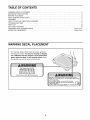
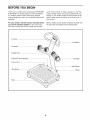
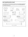
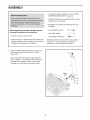
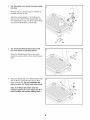
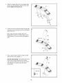
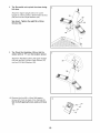
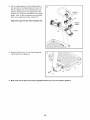
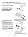
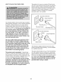
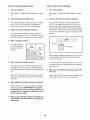
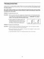
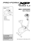
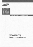
-lr|
TM
Model No. 83t.14787.0
Serial No.
Write the serial number in the
space above for reference,
USER'S MANUAL
Serial
Number
Decal
• Assembly
• Operation
• Troubleshooting
• Part List and Drawing
Sears, Roebuck and Co., Hoffman Estates, IL 60179
TABLE OF CONTENTS
WARNING DECAL PLACEMENT ..............................................................
IMPORTANT PRECAUTIONS
................................................................
BEFORE YOU BEGIN ......................................................................
PART IDENTIFICATION CHART ..............................................................
ASSEMBLY ...............................................................................
HOW TO USE THE VIBRATION PLATFORM ...................................................
TROUBLESHOOTING
.....................................................................
PART LIST ..............................................................................
EXPLODED DRAWING ....................................................................
ORDERING REPLACEMENT PARTS ..................................................
90 DAY FULL WARRANTY ..........................................................
2
3
5
6
7
13
17
18
19
Back Cover
Back Cover
WARNING DECAL PLACEMENT
The warning decals shown here have been applied in
the locations shown. If a decal is missing or illegible,
call 1-888-533-1333 and request a free replacement
decal. Apply the decal in the location shown. Note:
The decals may not be shown at actual size.
User Weight: Max 300 LBS
Weight Crutch: Max 310 LBS
Leg Developer: Max 150 LBS
Weight Carriage: Max 150 LBS
Chest Fly Per Arm: Max 50 LBS
Product
may not offer all listed exercises.
• Misuse of this machine may result in serious injury.
• Read user's manual prior to use and follow
all warnings
and instructions.
• Do not allow children on or around machine.
• Keep body, clothing, and hair free and clear of
all moving parts.
label if dama
or removed
2
IMPORTANT PRECAUTIONS
3
4
BEFORE YOU BEGIN
Thank you for selecting the revolutionary PROFORM ®
ACTIVATOR V7 vibration platform. The ACTIVATOR
V7 vibration platform offers whole body vibration
options designed to make tour workouts effective and
enjoyable.
cover of this manual. To help us assist you, note the
product model number and serial number before contacting us. The model number and the location of the
serial number decal are shown on the front cover of
this manual.
For your benefit, read this manual carefully before
you use the vibration platform. If you have questions after reading this manual, please see the back
Before reading further, please familiarize yourself with
the parts that are labeled in the drawing below.
Console
Handlebar
Dumbbell
Weight Rest
Reset/Off Circuit Breaker
Dumbbell
Power Cord
Start Button
Stop Button
Wheel
Base
5
PART IDENTIFICATION
CHART
See the drawings below to identify small parts used in assembly, The number in parentheses by each drawing is
the key number of the part, from the PART LIST near the end of this manual. Note: Some small parts may
have been preattached. If a part is not in the hardware kit, check to see if it has been preattached. If a
part is missing, call t-888-533-t333.
©D
M10 Nylon
Locknut (32)
M5 x 38mm Screw (40)
M4 x 16mm
Patch Screw (26)
MIO Split
Washer (38)
MIO x 20mm
M4 x 19mm
Screw (45)
M!0 x 35mm Screw (34)
Patch Screw (28)
M10 x 55mm Patch Screw (20)
M!O x 50mm Patch Screw (5!)
H
M!0 x 62ram Patch Screw (37)
M10 x 68mm Bolt (55)
M10 x 114mm Bolt (33)
6
ASSEMBLY
• For help identifying small parts, see the PART
IDENTIFICATION CHART on page 6.
• Tighten all parts as you assemble them, unless
instructed to do otherwise.
• Assembly may require the following tools (not
included):
Before beginning assembly, carefully read the
following information and instructions:
one adjustable wrench
• Assembly requires two persons.
one Phillips screwdriver
one rubber mallet
• Place all parts in a cleared area and remove the
packing materials. Do not dispose of the packing
materials until assembly is completed.
1,
Assembly will be more convenient if you have a
socket set, a set of open-end or closed-end
wrenches, or a set of ratchet wrenches.
Attach a Rubber Spacer (29) and a Foot (13) to
the Lower Upright (!) with an M!0 x 35mm
Screw (34).
Next, locate the Wire Harness (43) inside the
Lower Upright (!). Connect the Wire Harness to
the base wire as shown. Then, pull the Wire
Harness out of the top of the Lower Upright.
Base
Wire
7
2. Tip: Be careful not to pinch the wires during
this step.
With the help of a second person, carefully tip
the Base (5) onto its side.
Attach the Lower Upright (1) to the Base (5)
with two M10 x 55mm Patch Screws (20), two
M10 Split Washers (38), two M10 x 68ram Bolts
(55), and two M10 Nylon Locknuts (32).
20
38
3. Tip: Orient the Wheel Bracket (35) so that
the arrow sticker is pointing upward.
28
Attach the Wheel Bracket (35) to the Lower
Upright (1) with two M10 x 20mm Patch Screws
(28).
4.
Attach the Wheel (30) to the Wheel Bracket (35)
with an M!0 x 114mm Bolt (33) and an M!0
Nylon Locknut (32). Do not overtighten the
Nylon Locknut; the Wheel must rotate freely.
32
3O
Note: If the Wheel (30) rattles when the
vibration platform is in use, tighten the M1O
Nylon Locknut (32) until the rattling stops.
33
8
5.
Attach the Weight Rest (42) to the Weight Rest
Frame (41) with eight M5 x 38ram Screws (40).
Do not tighten the Screws yet.
5
42
40
40
40
6,
Locate the wire tie inside the Upper Upright (36).
Insert the wire tie through the hole in the Weight
Rest Frame (41).
Next, attach the Upper Upright (36) to the
Weight Rest Frame (41) with two M10 x 50ram
Patch Screws (51) and two M!0 Split Washers
(38).
Wire Tie ,..__)
Hole
/
7,
Have a second person hold the Upper Upright
(36) near the Lower Upright (1).
See the inset
wire tie to the
Then, pull the
Wire Harness
Upright (36).
drawing. Tie the lower end of the
Wire Harness (43) as shown.
upper end of the wire tie until the
is routed through the Upper
ire Tie
43
9
8. Tip: Be careful not to pinch the wires during
this step.
Attach the Upper Upright (36) to the Lower
Upright (1) with four M10 x 20mm Patch Screws
(28) and four M!0 Split Washers (38).
28
See step 5. Tighten the eight M5 x 38ram
Screws (40).
28
9. Tip: Orient the Handlebar (39) so that the
sticker with an "R" is in the location shown.
Attach the Handlebar (39) to the Upper Upright
(36) with two M10 x 62mm Patch Screws (37)
and two M10 Split Washers (38).
10. Remove the four M4 x 12ram Self-tapping
Screws (27) from the back of the Console (3).
Set the Self-tapping Screws aside until step
13.
10
27
27
10
11. Attach the back of the Console (3) to the Upper
Upright (36) with two M4 x 16mm Patch Screws
(26). Do not tighten the Screws yet.
11
3
26
12. While a second person holds the Front of the
Console (3) near the Upper Upright (36), connect the console ground wire to the Ground
Wire (52). Next, connect the console wire to the
Wire Harness (43). Then, insert the wires into
the Upper Upright.
12
13. Tip: Be careful not to pinch the wires during
this step.
13
3_.
Console
Console
27
Attach the front of the Console (3) to the back
of the Console with the four M4 x 12mm Selftapping Screws (27) you removed in step 10
and an M4 x 19ram Screw (45).
27
See step tt. Tighten the two M4 x 16ram
Patch Screws (26).
45
11
14. Set ten weight plates into the indicated slots in
the right side of the Weight Rest (42). Next, lift
the two selector pins on a Dumbbell (44), and
slide the selector pins to the adjustment holes
marked "2.5." Place the Dumbbell on the weight
plates. Then, lift the two selector pins and slide
them to the adjustment holes marked "15."
14
Selector
,Pins
Repeat this step with the other Dumbbell (44).
Weight
42
15. Plug the Power Cord (17) into the Receptacle
(!8) located on the Base (5).
17
16. Make sure that all parts are properly tightened before you use the vibration platform.
12
Slots
HOW TO USE THE VIBRATION
PLATFORM
HOW TO MOVE THE VIBRATION PLATFORM
Before moving the vibration platform, unplug
the power cord and remove the dumbbells from
the weight rest.
Hold the handlebar and place one foot against the
wheel. Tilt the vibration platform until it rolls freely
on the wheel. Carefully move the vibration platform
to the desired location. To reduce the risk of
injury, use extreme caution while moving the
vibration platform. Do not move the vibration
platform over an uneven surface.
Wheel
Dumbbell
Dumbbell
HOW TO USE THE ADJUSTABLE-WEIGHT
DUMBBELLS
Each dumbbell handle can be used with two, four,
six, eight, or ten weight plates; each dumbbell ham
die can also be used without weight plates.
Selector
Pin
To select the desired number of weight plates, first
set a dumbbell on the weight rest as shown. Next,
lift one of the selector pins, slide the selector pin to
one of the adjustment holes, and then release the
selector pin. Rock the selector pin from side to side
to make sure that it is fully inserted into one of the
adjustment holes. Adjust the other selector pin on
the dumbbell in the same way. Always attach the
same number of weight plates to both sides of
each dumbbell handle.
Handle
Weight
Weight
Rest
To use the dumbbell, lift it straight upward off the
weight rest, making sure that the unattached weight
plates remain on the weight rest.
13
HOW TO PLUG IN THE POWER CORD
This product is for use on a nominal 12g-volt circuit,
and has a grounding plug that looks like the plug illustrated in drawing 1 below. Atemporary adapter that
looks like the adapter illustrated in drawing 2 may be
used to connect the surge suppressor to a 2-pole
receptacle as shown in drawing 2 if a properly
grounded outlet is not available.
_Grounded
_.1
Your vibration platform, like any other type of sophisticated electronic equipment, can be seriously damaged
by sudden voltage changes in your home's power.
Voltage surges, spikes, and noise interference can
result from weather conditions or from other appliances
being turned on or off. To decrease the possibility of
your vibration platform being damaged, always
use a surge suppressor with your vibration platform (see drawing t at the right). To purchase a
surge suppressor, see your local Sears store or
call the telephone number on the back cover of
this manual and order part number 146148, or see
your local electronics store.
_
Outlet Box
_SurgeSupp
_r_ln"_l
G ou de
I: l_'J
O
ressor
GroLlnding Pin
e
Grounding Plug_
2
Grounded
Outlet Box
Adapter
i_1_
Use only a single-outlet surge suppressor that is
UL t449 listed as a transient voltage surge suppressor (TVSS). The surge suppressor must have
a UL suppressed voltage rating of 400 volts or less
and a minimum surge dissipation of 450 joules.
The surge suppressor must be electrically rated
for t20 volts AC and t5 amps. There must be a
monitoring light on the surge suppressor to indicate whether it is functioning properly.
Metal Screw
Surge suppressor
_
The temporary adapter should be used only until a
properly grounded outlet (drawing 1) can be installed
by a qualified electrician.
The green-colored rigid ear, lug, or the like extending
from the adapter must be connected to a permanent
ground such as a properly grounded outlet box cover.
Whenever the adapter is used it must be held in place
by a metal screw. Some 2-pole receptacle outlet
box covers are not grounded. Contact a qualified
electrician to determine if the outlet box cover is
grounded before using an adapter.
This product must be grounded. If it should malfunction or break down, grounding provides a path of
least resistance for electric current to reduce the risk
of electric shock. This product is equipped with a cord
having an equipment-grounding conductor and a
grounding plug. Plug the power cord into a surge
suppressor, and plug the surge suppressor into an
appropriate outlet that is properly installed and
grounded in accordance with all local codes and
ordinances. IMPORTANT: The vibration platform is
not compatible with GFCl-equipped
outlets.
14
CONSOLE DIAGRAM
f
CONSOLE FEATURES
you do not do this, the console or other electronic
components may become damaged.
The console offers a selection of features designed to
make your workouts more effective and enjoyable.
You can change the time and frequency of your vibration sessions with the touch of a button,
Plug the power cord
into the receptacle on
the base of the vibration platform (see
Position
Reset
assembly step 15 on
page 12). Then, plug
the power cord into a
120-volt outlet. Next,
locate the reset/off circuit breaker on the vibration platform near the power cord. Make sure that the circuit
breaker is in the reset position.
The console also features the new iFIT Interactive
Workout System. The iFIT Interactive Workout System
is compatible with iFIT cards containing workout programs designed to help you achieve specific fitness
goals. IFIT programs control the time and frequency of
the vibration platform while the voice of a personal
trainer coaches you and motivates you through your
workouts. IFIT cards are available separately. To purchase iFIT cards, go to www.iFIT.com or call t-888533-t333. iFIT cards are also available at select
stores.
EXERCISE FORM
See the accompanying exercise DVD to learn the correct form for several exercises that can be performed
on the vibration platform. When standing on the vibration platform, bend your knees slightly and balance
your weight on the balls of your feet.
HOW TO TURN ON THE POWER
IMPORTANT: If the vibration platform has been
exposed to cold temperatures,
allow it to warm to
room temperature before turning on the power. If
15
HOW TO USE THE MANUAL MODE
HOW TO USE AN IFIT PROGRAM
1.
1. Turn on the power.
Turn on the power.
See HOW TO TURN ON THE POWER on page
15.
2.
See HOW TO TURN ON THE POWER on page
15.
Select the desired vibration time.
2.
Press the desired time button to select a vibration
To use an iFIT program, insert an iFIT card into
the iFIT slot; make sure that the iFIT card is oriented so the metal contacts are face down and
time of 30, 45, or 60 seconds. The display will
show which length of time you have selected.
3.
are facing the slot. When the iFIT card is properly
inserted, the indicator next to the slot will light and
the number of the iFIT program will appear in the
display.
Select the desired vibration frequency.
Press the desired frequency button to select a
vibration frequency of 25, 30, or 35 hertz. The display will show which frequency you have selected.
4.
Insert an iFIT card and select a program.
Start a vibration session.
Press the start button on the platform
to start a vibration
session.
Stop
Button
\
\
iFIT Slot
[_
Start
iFIT Card
Next, select the desired program on the iFIT card
by pressing the increase and decrease buttons
next to the iFIT slot.
5.
Stop or pause a vibration session.
A moment after you select a program, the voice of
a personal trainer will begin guiding you through
your workout.
Press the stop button (see the drawing above) on
the platform to stop or pause a vibration session.
Press the start button to continue the vibration session.
.
Note: When the session ends, a tone will sound to
alert you, and the vibration platform will automatically stop.
6.
Start additional
exercising,
remove the
Remove the iFIT card when you are finished exercising. Store the iFIT card in a secure place.
vibration sessions as desired.
Repeat steps 2-5 for as many additional vibration
sessions as desired. IMPORTANT: It is recommended that you use the vibration platform for
no more than 15 minutes per day and no more
than 3 times per week.
7.
When you are finished
iFIT card.
When you are finished, switch the reset/off circuit breaker to the off position and unplug the
power cord.
16
TROUBLESHOOTING
Inspect all parts of the vibration platform regularly. Replace any worn parts immediately. Outer surfaces of the vibration platform can be cleaned with a damp cloth and a mild, non-abrasive detergent; do not use solvents to clean
the vibration platform.
Most vibration platform problems can be solved by following the simple steps below. Find the symptom
that applies, and follow the steps listed. If further assistance is needed, call the telephone number listed
on the back cover of this manual.
PROBLEM:
The power does not turn on
SOLUTION: a. Make sure that the power cord is plugged into a surge suppressor, and that the surge suppressor is plugged into a properly grounded outlet (see page 14). Use only a single-outlet surge suppressor that meets all of the specifications described on page 14. IMPORTANT: The vibration
platform is not compatible with GFCl-equipped outlets.
b.
PROBLEM:
Check the reset/off circuit breaker located on the
vibration platform frame near the power cord. If
the switch protrudes as shown, the circuit breaker
has tripped. To reset the circuit breaker, wait for
five minutes and then press the switch back in.
c
Tripped
Reset
The power turns off during use
SOLUTION: a. Check the reset/off circuit breaker (see the drawing above). If the circuit breaker has tripped,
wait for five minutes and then press the switch back in.
b. Make sure that the power cord is plugged in. If the power cord is plugged in, unplug it, wait for
five minutes, and then plug it back in.
c. If the vibration platform still will not run, please see the back cover of this manual.
17
PART LIST--Model
Key No. Qty.
No. 831.14787.0
Description
Ro4o8A
Key No.
Qty.
Description
1
2
3
4
5
6
1
1
1
1
!
1
Lower Upright
Platform Cover
Console
Platform Plate
Base
Vibration Platform
32
33
34
35
36
37
3
!
5
1
1
2
M10 Nylon Locknut
M10 x 114mm Bolt
M10 x 35mm Screw
Wheel Bracket
Upper Upright
M10 x 62mm Patch Screw
7
8
9
1
!
!
Stop Button
Start Button
Controller Box
38
39
40
10
!
8
M10 Split Washer
Handlebar
M5 x 38mm Screw
10
11
12
1
!
1
Controller
Controller Cover
Motor
41
42
43
1
!
!
Weight Rest Frame
Weight Rest
Wire Harness
13
14
15
5
4
4
Foot
Shock Absorber Cover
Shock Absorber
44
45
46
1
!
4
Dumbbell (Pair)
M4 x 19mm Screw
M8 Washer
16
17
4
1
Platform Endcap
Power Cord
47
48
4
4
M8 Split Washer
Frame Cover
18
19
20
21
1
1
2
2
Receptacle
Reset/Off Circuit Breaker
M10 x 55mm Patch Screw
Star Washer
49
50
51
52
1
1
2
1
Motor Mounting Bracket
Motor Cover
M10 x 50mm Patch Screw
Ground Wire
22
23
24
25
26
27
28
29
30
31
2
2
4
4
2
4
6
1
1
4
Spring
M8 x 16mm Screw
M!0 x 46mm Flat Head Screw
M8 x 30ram Screw
M4 x 16mm Patch Screw
M4 x 12mm Self-tapping Screw
M10 x 20mm Patch Screw
Rubber Spacer
Wheel
M4 x 8mm Screw
53
54
55
56
3
1
2
1
-
M4 x 12mm Screw
Grommet
M10 x 68mm Bolt
Switch Wire Harness
Wiring Tie
Hex Key
User's Manual
DVD
iFIT Demo Card
Note: Specifications are subject to change without notice. See the back cover of this manual for information about
ordering replacement parts. *These parts are not illustrated. If a part is missing, call 1-888-533-t333.
18
EXPLODED DRAWING--
Model No. 831.14787.0
Ro4oaA
27
27
45
26 _52
42
23
40
28
38
38
30
28
5
43
54
25
17
19
Your Home
For repair--in
or heating
your home--of
all major brand appliances, lawn and garden equipment,
and cooling systems, no matter who made it, no matter who sold it!
For the replacement
parts, accessories,
and user's manuals that you need to do-it-yourself.
For Sears professional installation of home appliances
and items like garage door openers and water heaters.
1-800-4-MY-HOME
_ (1-800-469-4663)
Call anytime, day or night (U.S.A. and Canada)
www.sears.com
www.sears,ea
Our Home
For repair of carry-in items like vacuums, lawn equipment,
and electronics, call or go on-line for the location of your nearest
Sears Parts & Repair Center.
1-800-488-1222
Call anytime, day or night (U.S.A only)
www.sears.corn
TO purchase a protection agreement (U.S.A.)
or maintenance agreement (Canada) on a product serviced by Sears:
Sears
(_) Registered
Trademark
/ T_ Trademark
,_) Marca
Registrada
/ 1M Marca de Fabrica
/ SM Service
Mark of Sears
Brands
LLC
/ sf4 Marca
de Servicio
de Sears Brands,
LLC
90 DAY FULL WARRANTY
this Sears Vibration Platform fails due to a defect in material or workmanship within 90 days of the
date of purchase, call !-800-4-MY-HOME ¢' (!-800-469-4663) to arrange for free repair (or replacement
if repair proves impossible). There is a five year warranty on the frame.
This warranty does not apply when the Vibration Platform is used commercially or for rental purposes.
This warranty gives you specific legal rights, and you may also have other rights which vary from state
to state.
Sears, Roebuck and Co., Hoffman Estates, IL 60179
/
J
Part No. 264767 R0408A
Printed in China © 2008 ICON IP, Inc.