1
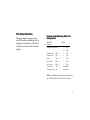
This manual covers installation and operating instructions for the following U.S. Robotics modems: • Sportster 56K* faxmodem for Macintosh computers Sportster, U.S. Robotics, and the U.S. Robotics logo are registered trademarks and Connections, x2, and the x2 logo are trademarks of U.S. Robotics. Macintosh is a registered trademark and Mac is a trademark of Apple Computer, Inc. MacComCenter is a trademark of Smith Micro Software, Inc. America Online is a registered trademark of America Online Inc. CompuServe is a registered trademark of CompuServe Inc. Other trademarks, trade names, and service marks owned or registered by any other company and used in this manual are the property of their respective companies. © 1997 U.S. Robotics 7770 North Frontage Road Skokie, IL 60077-2690 All Rights Reserved * IMPORTANT! This modem is 56Kbps capable. However, current FCC rules limit download speeds to 53Kbps. See page 3 for details. Table of Contents U.S. Robotics: The Intelligent Choice in Information Access™ 1 Welcome to x2™ Information Access 3 Features 5 Installation 7 Software and Registration 11 U.S. Robotics Online for Mac™ Users 13 Troubleshooting 17 Glossary 23 Technical Quick Reference 35 Front Panel Lights 36 Command Summary 37 S-Registers 50 Regulatory Information 59 Limited Warranty 69 U.S. Robotics: The Intelligent Choice in Information Access Congratulations! You have just purchased the Sportster® 56K faxmodem for Macintosh® computers. Since 1976, U.S. Robotics has grown to become a key manufacturer and developer of information access technology. U.S. Robotics' advanced technology allows you to use your faxmodem to open up a new world of information access. And now you can take advantage of the highest transfer rates available today with our new x2 technology! As an innovator in the data communications field, U.S. Robotics has a history of bringing the latest technology to market at an affordable price. market faster and at a lower cost while passing the savings on to you. Be sure to read the following section to learn more about the latest U.S. Robotics breakthrough, x2 technology. Your new Sportster takes advantage of this technology to make connecting over analog lines faster than ever before. For more information on U.S. Robotics, visit the U.S. Robotics Web Server at: http://www.usr.com. U.S. Robotics owns the core technology, known as the data pump, that works in its access products. This allows U.S. Robotics to bring new technologies and features to 1 Welcome to x2 x2 Information Access which restrict power output of your service provider’s modems, current download speeds are limited to 53Kbps. This modem is software upgradable, allowing easy upgrades to new features and enhancements when they become available. An integrated end-to-end solution from the leader The latest breakthrough in online communications Until now, 33.6 Kbps was thought to be the practical limit for speed over standard phone lines. Now, U.S. Robotics shatters that barrier, to bring you download speeds of up to 56 Kbps. However, due to FCC rules U.S. Robotics is well positioned to bring you x2 technology. Our Sportster® modems are the world's number one seller, and our Total ControlTM and CourierTM product lines are favored by many Internet service providers. This widespread acceptance allows U.S. Robotics to offer x2 technology to virtually anyone. 3 Taking advantage of the modern telephone network x2 technology uses the increasingly digital telephone network to bring you faster downloads by eliminating the analog-todigital conversion in the downstream path. x2 takes advantage of the typical network configuration found when an analog subscriber connects to a digitally connected server. x2 bypasses the analog-to-digital conversion in the downstream path to use nearly all of the available 64K network bandwidth. (Upstream data, typically less speed sensitive, travels at the standard V.34 rate.) The result is a completely new kind of transmission technique. Based on “encoding” rather than “modulation,” it can give you download speeds that you never thought possible. What’s more, with 4 standard V.42 bis compression, x2 can download at speeds up to a blistering 115.2 Kbps. The new standard for online speed U.S. Robotics has already submitted x2 technology to the ITU-T standards committee for acceptance as the next online standard. For more information on U.S. Robotics’ x2 technology, see our World Wide Web page at http://x2.usr.com. Features Data Communications V.42/MNP 2-4 error control and V.42 bis/MNP 5 data compression. Your new modem will transmit at speeds up to 33.6Kbps. And with x2 technology, you can download at speeds up to 56Kbps∗. This will save you money in online service charges and long distance bills. Fax Capability Not only is your modem fast, it is compatible with internationally accepted standards which allow you to connect to other modems across the globe. These standards include: V.34+, V.32 bis, V.32, V.22 bis, Bell 212A/V.22, V.23, V.25, and Bell 103/V.21 modems. Your modem is compatible with Class 1 or Class 2.0 fax software included in your package to exchange faxes with Group III fax machines worldwide at speeds up to 14.4 kbps. ∗ Current FCC rules limit download speeds to 53Kbps. To send data faster and more efficiently, your modem uses hardware-based 5 Installation Getting Started Before you begin, make sure that the following items are at hand: Install your modem: 1. This package: modem, RJ11 (standard) phone cord, power adapter, serial connecting cable, this guide. 2. Firmly attach the enclosed serial connecting cable to both the modem and the port on the back of your computer marked with a telephone icon. 2. Not with this package: analog (standard) phone jack. 1. Turn off your computer. 7 3. Connect the power adapter to your modem and plug it into the wall. 4. Plug one end of the phone cord into the telephone jack of the modem (labeled with a wall plug icon on the bottom of the case) and the other end into the telephone jack. If you wish to use your modem and phone with the same telephone wall jack, plug your phone’s cord into the other available port on the back of your modem. Once your modem is connected, you’ll need to install the MacComCenter software included with your modem. This allows you to send and receive faxes, surf the Internet, call an online service to access e-mail, or call a local bulletin board (BBS). For more information on installing the communications software and other applications included with your modem, see the Software and Registration chapter. 8 The Serial Interface Macintosh computers require an 8-pin mini-DIN hardware handshaking cable for high-speed communications. This cable is included in your Sportster for Macintosh package. Hardware Handshaking Cable Pin Assignments Mini DIN-8 Connector DB-25 Handshake Output HSKo 1 4 RTS 20 DTR Handshake Input HSKi 2 5 CTS Transmit Data+ TXD- 3 2 TXD Ground GND 4 7 GND Receive Data+ RXD+ 8 7 GND Receive Data- RXD- 3 RXD Transmit Data+ TXD+ 6 Gen. Purpose Input GPI 5 7 not connected not connected Note: The Handshake Output pin is connected to both pins 4 (RTS) and 20 (DTR) on the DB-25 connector. 9 Software and Registration MacComCenter ™ Software MacComCenter, a software application designed by Smith Micro Software, Inc., is included with your new Sportster modem. Follow these instructions to install the software. Please refer to the electronic MacComCenter user’s guide on your Connections™ CD for details about operating the software. Follow these steps to install MacComCenter: 1. Quit all other applications. 2. Insert the Connections CD-ROM into your CD-ROM drive. 3. Double-click on the U.S. Robotics Connections icon. 4. Follow the on-screen directions to install the Connections software onto your computer. NOTE: ARA scripts install along with MacComCenter. 11 Registration We recommend you fill out the enclosed registration card and send it back to us. Registering your modem allows you to automatically receive priority notification of new product releases, product upgrades, and other special services for registered users. 12 U.S. Robotics Online for Mac™ Users Downloading Enhanced Graphics Software U.S. Robotics has a Mac™ specific BBS. Please follow these instructions to view the Mac BBS with enhanced graphics capabilities. 1. Start your communications software and enter Terminal (sometimes called Command) mode. The software settings for the BBS are as follows: ANSI terminal emulation Data Bits: 8 Parity: None Stop Bits: 1 2. Enter the following command: ATDT 1-847-676-1598 13 (If you get a busy signal, use the A/ command to redial the number.) 3. Once you are connected, type MMM. 4. Next, select the Download TeleFinder/User for Macintosh option from the menu. This downloads special software used when logging onto the Macintosh BBS at U.S. Robotics. Using TeleFinder to access the Macintosh BBS at U.S. Robotics Follow these steps to run the TeleFinder software and log onto the Macintosh BBS at U.S. Robotics: 1. Double-click on the TeleFinder/User 4.0.sea icon in your hard drive. This will install the TeleFinder application onto your hard drive. 2. Double-click on the new TeleFinder/User 4.0 icon. 3. Enter your name and choose a password. Next, select Modem from the same screen. You will now be asked to select/double-click on the modem you purchased. Click on the U.S. Robotics Sportster model you purchased. 4. Type 1-847-676-1598 in the Telephone Number box. 5. Click the OK box, followed by the Connect box. The modem should now connect to our site at U.S. Robotics. Congratulations! You have successfully logged onto the Macintosh BBS at U.S. Robotics. From here you can download technical reference manuals or learn more about U.S. Robotics by clicking on the various icons. 14 Other U.S. Robotics Support Sites and Services Internet FTP Provides a free library containing the same files as the BBS site. FTP to ftp.usr.com. Internet On Demand Provides automatic technical support through a library containing product information, quick reference cards, and installation help. To obtain an index of available documents, send blank e-mail to [email protected]. To have a document e-mailed to you, send the document's multi-digit number as the subject. World Wide Web A U.S. Robotics Home Page containing much of the same information as the Internet on Demand listing as well as information about U.S. Robotics. Log on to http://www.usr.com. Fax on Demand Provides automatic technical support via fax with immediate response. This service provides documents on product information, quick reference cards and installation help. Call (800) 762-6163 toll free in the U.S. and Canada. International callers dial (847) 6768536. CompuServe Connect through the Modem Vendor Forum or e-mail us through CompuServe Mail for a response within 24 hours. Modem vendor forum address is GO USROBOTICS, Modem Vendor Section #4. Address message to 76711,707. Send messages directly to us through CompuServe Mail at 76711,707. America Online Connect to U.S. Robotics through America Online. Go to the Keyword field and type USROBOTICS to participate in the various online message forums or to download files from the library. 15 Fax and Technical Support Hotline Technical questions about U.S. Robotics modems can also be answered via fax or by live technical support representatives. Fax (847) 676-7323 (The fax machine can receive faxes 24 hours a day.) Technical Support (847) 982-5151 (8:00 a.m.—6:00 p.m., Mon.–Fri., Central time) Priority “No Hold” Service (900) 555-USR1 (8:00 a.m.—6:00 p.m., Mon.–Fri., Central time) 16 Troubleshooting Before the modems connect… If your modem doesn't respond to any AT commands, • Make sure the modem is on. • Make sure the computer is in Terminal mode. • Type in all upper (AT) or lower (at) case. • Check that the bit rate is not 14,400 or 28,800. If your modem displays double characters on your monitor (example: AATT), • You can turn the local echo off on the modem by typing ATEO <enter> in your software’s terminal mode. To turn the local echo off in the software, refer to your software’s documentation. If your modem doesn't dial a number or doesn't answer the phone, • • • • • Make sure the phone cord is connected to the jack on the modem labeled TELCO and to a phone jack. Review your software documentation to see what DTR operations are required. For MacComCenter and most other Mac applications, dip switch 1 should be down and &D0 should be in the init string. Check that the bit rate is not 14,400 or 28,800. Also, try dialing with ATX3DT as the dial string. For answering, make sure that your software has auto answer enabled. 17 If both modems exchange carrier signals but fail to establish a communications link, • • • 18 Place the call again. The telephone company routes all calls, even local calls, differently each time you call. Call a different modem to see if the problem persists. The remote modem might be an older 2400 bps modem that doesn't support error control. Disable error control by entering the following command in terminal mode: AT&M0<Enter> and place the call again. If your modem doesn't connect at 2400 bps with a 2400 bps modem, The remote modem might be an older 2400 bps modem that does not support error control. Disable error control with the following command: AT&M0<Enter> and try connecting again. When the call is finished, reset the modem: ATZ<Enter>. During data transfer… If your screen displays random or garbage characters, • Set your software to the same word length, parity, and stop bits as the remote modem. • • Make sure that your software and modem are set to the same flow control setting and to a fixed serial port rate (it should not be 14,400 or 28,800). Type the following command to load the template that enables hardware flow control and other optimal settings: AT&F1&D0<Enter> If your communications software is reporting many Cyclic Redundancy Check (CRC) errors and low Characters Per Second (CPS), • • • • Type the following command to load the template that enables hardware flow control and optimal settings: AT&F1&D0<Enter> Lower the serial port rate in your communications software to 38,400 bps or 19,200 bps. Try a different file transfer protocol. Zmodem is best. Ymodem is second best. If errors are occurring in your V.17 (14.4) fax transmissions, • Enter the following initialization string in your software modem setup screen: AT&D0&H3&I2&R2S7=90 You might have a bad phone line. Place the call again. The phone company routes calls differently each time you call. 19 Are you still having problems? • • • • 20 Review this manual. Call or visit your modem dealer. They will be able to give you assistance. If you’re able, take advantage of support available through U.S. Robotics’ various online support sites. You can access them at the addresses listed on this page and in your Quick Install Guide. If your dealer cannot help you and you cannot access the online support sites, please contact U.S. Robotics Customer Support. When you call, please have your modem’s serial number (found on the modem and on the outside of the box), the name of the software being used, and, if possible, the contents of your ATI7 screen ready. USR Mac BBS: (847) 676-1598 Fax On Demand: (800) 762-6163 CompuServe: GO USROBOTICS America Online: keyword: USROBOTICS Internet: [email protected] World Wide Web: http://www.usr.com Fax: (847) 676-7323 Technical Support: (847) 982-5151 Priority “No Hold” Service: (900) 555-USR1 Internet FTP: ftp.usr.com 21 If you must return the modem to us... • • • • 22 Call U.S. Robotics Customer Support. When you call, please have your modem serial number (found on the modem and on the outside of the box) ready. After a Support Representative has determined that you need to return the modem, they will give you a Service Request Order (SRO) number. Ship the unit, postage paid, in a strong box made of corrugated cardboard with plenty of packing material. Include your SRO number, name, and address on the shipping label as well as inside the package. Ship to the following address: U.S. Robotics U1 Receiving SRO # U.S. Robotics Access Corp. 8100 N. McCormick Blvd. Skokie, IL 60076-2999 Glossary Cross references are printed in boldface. Cross references with items in the Command Summary chapter are printed in italics. Analog Loopback A modem self-test in which data from the keyboard or an internal test pattern is sent to the modem's transmitter, modulated into analog form, looped back to the receiver, and demodulated into digital form. Analog Signals A variety of signals and wavelengths that can be transmitted over communications lines such as the sound of a voice over the phone line. Contrast with digital signals. Answer Mode The mode used by your modem when answering an incoming call from an originating modem. The transmit/receive frequencies are the reverse of the originating modem, which is in Originate mode. Application A computer program designed to perform a specific function, such as a word processor or a spreadsheet. ARQ Automatic Repeat reQuest. A general term for a function that automatically allows your modem to detect flawed data and retransmit it. See MNP and V.42. 23 ASCII American Standard Code for Information Interchange. A 7-bit binary code (0s, 1s) used to represent letters, numbers, and special characters such as $, !, and /. Asynchronous Transmission Data transmission in which the length of time between transmitted characters may vary. Because the time lapses between transmitted characters are not uniform, the receiving modem must be signaled as to when the data bits of a character begin and when they end. The addition of Start and Stop bits to each character serves this purpose. Auto Answer Sets the modem to pick up the phone line when it detects a certain number of rings. See S-register (S0) in the Technical Quick Reference. 24 Baud Rate A term used to measure the speed of an analog transmission from one point to another. Although not technically accurate, baud rate is commonly used to mean bit rate. Binary Digit A 0 or 1, reflecting the use of the binary numbering system (only two digits). Used because the computer recognizes either of two states, OFF or ON. Shortened form of binary digit is bit. Bit Rate Also referred to as transmission rate. The number of binary digits, or bits, transmitted per second (bps). Communications channels using telephone channel modems are established at set bit rates, commonly 300, 1200, 2400, 4800, 9600, 14,400, and higher. Bits Per Second (BPS) The bits (binary digits) per second rate. Thousands of bits per second are expressed as kilobits per second or kbps. Carrier A tone signifying a connection the modem can alter to communicate data across telephone lines. Buffer A memory area used as temporary storage during input and output operations. An example is the modem's command buffer. Character A representation, coded in binary digits, of a letter, number, or other symbol. Byte A group of binary digits stored and operated upon as a unit. A byte may have a coded value equal to a character in the ASCII code (letters, numbers) or have some other value meaningful to the computer. In user documentation, the term usually refers to 8-bit units or characters. 1 kilobyte (KB) is equal to 1,024 bytes or characters; 640 KB indicates 655,360 bytes or characters. Characters Per Second (CPS) A data transfer rate generally estimated from the bit rate and the character length. For example, at 2400 bps, 8-bit characters with Start and Stop bits (for a total of ten bits per character) will be transmitted at a rate of approximately 240 characters per second (cps). Some protocols, such as error-control protocols, employ advanced techniques such as longer transmission frames and data compression to increase cps. 25 Class 1 and 2.0 International standards used between facsimile application programs and facsimile modems for sending and receiving faxes. Cyclic Redundancy Checking (CRC) An error-detection technique consisting of a cyclic algorithm performed on each block or frame of data by both sending and receiving modems. The sending modem inserts the results of its computation in each data block in the form of a CRC code. The receiving modem compares its results with the received CRC code and responds with either a positive or negative acknowledgment. Data Communications A type of communications in which computers are able to exchange data over an electronic medium. 26 Data Compression Table A table containing values assigned for each character during a call under MNP5 data compression. Default values in the table are continually altered and built during each call: the longer the table, the more efficient throughput gained. Data Mode The mode in which the fax modem is capable of sending and receiving data files. A standard modem without fax capabilities is always in data mode. DCE Data Communications (or CircuitTerminating) Equipment, such as dial-up modems that establish and control the data link via the telephone network. Default Any setting assumed, at startup or reset, by the computer's software and attached devices, and operational until changed by the user or software. Detect Phase In the ITU-T V.42 error-control protocol, the first stage in establishing whether both modems attempting to connect have V.42 capability. Dictionary The term used for compression codes built by the V.42 bis data compression algorithm. Digital Loopback A test that checks the modem's RS-232 interface and the cable that connects the terminal or computer and the modem. The modem receives data (in the form of digital signals) from the computer or terminal, and immediately returns the data to the screen for verification. Digital Signals Discrete, uniform signals. In this manual, the term refers to the binary digits 0 and 1. Contrast with analog signals. DTE Data Terminal (or Terminating) Equipment. A computer that generates or is the final destination of data. Duplex Indicates a communications channel capable of carrying signals in both directions. See Half Duplex, Full Duplex. EIA Electronic Industries Association, which defines electronic standards in the U.S. Error Control Various techniques that check the reliability of characters (parity) or blocks of data. V.42 and MNP error-control protocols use 27 error detection (CRC) and retransmission of flawed frames (ARQ). Facsimile A method for transmitting the image on a page from one point to another. Commonly referred to as fax. Fax Mode The mode in which the fax modem is capable of sending and receiving files in a facsimile format. See definitions for v.17, v.27ter, and v.29. Flow Control A mechanism that compensates for differences in the flow of data input to and output from a modem or other device. See commands &Hn, &In, and &Rn. 28 Frame A data communications term for a block of data with header and trailer information attached. The added information usually includes a frame number, block size data, error-check codes, and Start/End indicators. Full Duplex Signal flow in both directions at the same time. In microcomputer communications, may refer to the suppression of the online Local Echo. Half Duplex Signal flow in both directions, but only one way at a time. In microcomputer communications, may refer to activation of the online Local Echo, which causes the modem to send a copy of the transmitted data to the screen of the sending computer. Hz Hertz, a frequency measurement unit used internationally to indicate one cycle per second. protocols, LAPM uses cyclic redundancy checking (CRC) and retransmission of corrupted data (ARQ) to ensure data reliability. ITU-T An international organization that defines standards for telegraphic and telephone equipment. For example, the Bell 212A standard for 1200-bps communication in North America is observed internationally as ITU-T V.22. For 2400-bps communication, most U.S. manufacturers observe V.22 bis. The initials ITU-T represent the French name; in English it's known as the International Telegraph and Telephone Consultative Committee. Local Echo A modem feature that enables the modem to display keyboard commands and transmitted data on the screen. See command En. LAPM Link Access Procedure for Modems, an error-control protocol defined in ITU-T Recommendation V.42. Like the MNP 29 MNP Microcom Networking Protocol, an errorcontrol protocol developed by Microcom, Inc., and now in the public domain. There are several different MNP protocols, but the most commonly used protocol ensures error-free transmission through error detection (CRC) and retransmission of errored frames. Modem A device that transmits/receives computer data through a communications channel such as radio or telephone lines. It also changes signals received from the phone line back into digital signals before passing them to the receiving computer. Nonvolatile Memory (NVRAM) User-programmable random access memory whose data is retained when power is turned 30 off. On the Sportster, it includes four stored phone numbers and the modem settings. OFF/ON Hook Modem operations that are the equivalent of manually lifting a phone receiver (taking it off-hook) and replacing it (going on-hook). Online Fallback/Fall Forward A feature that allows high-speed, errorcontrol modems to monitor line quality and fall back to the next lower speed in a defined range if line quality diminishes; as line conditions improve, the modems switch up to the next higher speed. Originate Mode The mode used by your modem when initiating an outgoing call to a destination modem. The transmit/receive frequencies are the reverse of the called modem, which is in Answer mode. Parity A simple error-detection method that checks the validity of a transmitted character. Character checking has been surpassed by more reliable and efficient forms of error checking, including the V.42 and the MNP 2-4 protocols. Either the same type of parity must be used by two communicating computers or both may omit parity. Protocol A system of rules and procedures governing communications between two or more devices. Protocols vary, but communicating devices must follow the same protocol in order to exchange data. The format of the data, readiness to receive or send, error detection and error correction are some of the operations that may be defined in protocols. RAM Random access memory. Memory that is available for use when the modem is turned on but that clears all information when the power is turned off. The modem's RAM holds the current operational settings, a flow control buffer, and a command buffer. Remote Digital Loopback A test that checks the phone link and a remote modem's transmitter and receiver. Remote Echo A copy of the data received by the remote system, returned to the sending system, and displayed on the screen. Remote echoing is a function of the remote system. ROM Read Only Memory. Permanent memory, not user-programmable. 31 Serial Transmission The consecutive flow of data in a single channel. Compare to parallel transmissions where data flows simultaneously in multiple channels. Start/Stop Bits The signaling bits attached to a character before the character is transmitted during asynchronous transmission. Terminal A device whose keyboard and display are used for sending and receiving data over a communications link. Differs from a microcomputer or a mainframe in that it has little or no internal processing capabilities. Terminal Mode Software mode that allows direct communication with the modem. Also known as command mode. 32 Throughput The amount of actual user data transmitted per second without the overhead of protocol information such as Start and Stop bits or frame headers and trailers. Compare with characters per second. V.8 The portion of the V.34 specification that covers the handshaking process. V.17 Fax A ITU-T standard for making facsimile connections at 14,400 bps, 12,000 bps, 9,600 bps, and 7,200 bps. V.21 A ITU-T standard for modems operating in asynchronous mode at 300 bps, full-duplex, on public switched telephone networks. V.22 A ITU-T standard for modem communications at 1200 bps, compatible with the Bell 212A standard observed in the U.S. and Canada. V.32 A ITU-T standard for modem communications at 9600 bps and 4800 bps. V.32 modems fall back to 4800 bps when line quality is impaired. V.22 bis A ITU-T standard for modem communications at 2400 bps. The standard includes an automatic link negotiation fallback to 1200 bps and compatibility with Bell 212A/V.22 modems. V.32 bis A ITU-T standard that extends the V.32 connection range: 4800, 7200, 9600, 12,000, and 14,400 bps. V.32 bis modems fall back to the next lower speed when line quality is impaired, fall back further as necessary, and also fall forward (switch back up) when line conditions improve. V.27 ter A ITU-T standard for facsimile operations that specifies modulation at 4800 bps, with fallback to 2400 bps. V.29 A ITU-T standard for facsimile operations that specifies modulation at 9600 bps, with fallback to 7200 bps. V.34 An ITU-T standard with recommendations that currently allow data rates as high as 33,600 bps. 33 V.42 A ITU-T standard for modem communications that defines a two-stage process of detection and negotiation for LAPM error control. Ymodem An error-checking protocol that can send several files of data at a time in 1024-byte (1K) blocks. This protocol can use either checksums or CRC for error checking. V.42 bis An extension of ITU-T V.42 that defines a specific data compression scheme for use during V.42 connections. Ymodem G Similar to Ymodem, except it includes no error checking, which makes it faster. Xmodem The first of a family of error control software protocols used to transfer files between modems. These protocols are in the public domain and are available from many bulletin board services. Zmodem Similar to Xmodem and Ymodem, except it includes batch transfer, the ability to recover from a partially complete transfer, an autostart feature, and improved efficiency. XON/XOFF Standard ASCII control characters used to tell an intelligent device to stop/resume transmitting data. 34 Technical Quick Reference The Quick Reference appendix includes information about: • • • Front Panel Lights Command Summary S-Registers 35 Front Panel Lights Symbol Meaning Status AA .......... Auto Answer......................Answer mode: ON when register S0 is set to 1 or higher (Auto Answer) and when answering a call; OFF when modem originates a call. Light flashes when there is an incoming call. CD........... Carrier Detect ....................ON if modem receives a valid data signal (carrier) from a remote modem, indicating that data transmission is possible. Always ON if CD override is ON (&C0). RD........... Received Data....................Flashes when modem sends result codes or passes received data bits from remote. SD ........... Send Data ..........................Flashes when computer sends a data bit to modem. TR ........... Data Terminal Ready.........ON if modem receives a DTR signal from computer. Always ON (modem ignores DTR) if the DTR override is ON (&D0). CS ........... Clear to Send .....................ON until modem lowers CTS when Transmit Data hardware flow control is enabled (&H1, &H3). ARQ/ Error Control/ Data Mode: Automatic Repeat Request. FAX ........ Fax Operations ..................ON if modem is set to &M4 or &M5 and successfully establishes an error control connection. Flashes when modem retransmits data to remote modem. Fax Mode: Flashes to indicate fax mode. 36 Command Summary • • • • Type commands in either upper or lower case, not a combination. Use the Backspace key to delete errors. (You cannot delete the original AT command since it is not stored in the modem buffer.) If a command has numeric options and you don’t include a number, zero is assumed. For example, if you type ATB, the command ATB0 is assumed. Every command except A/ and +++ must begin with the AT prefix and be entered by pressing <Enter>. The maximum command length is 58 characters. The modem doesn’t count the AT prefix, carriage returns, or spaces. Note: All defaults are based on the &F1Hardware Flow Control template loaded in NVRAM when the modem is shipped. Defaults are listed in italics. 37 Command Set $ Use in conjunction with D, S, or & commands (or just AT) to display a basic command list; online help. A Manual Answer: goes off hook in answer mode. Pressing any key aborts the operations. A/ Re-executes the last issued command. Used mainly to redial. This does not require the AT prefix or a Carriage Return. Any key Aborts off-hook dial/answer operation and hangs up. AT Required command prefix, except with A/ and +++. Use alone to test for OK result code. Bn U.S./ITU-T answer sequence. B0 ITU-T answer sequence B1 U.S. answer tone 38 Dn Dials the specified phone number. Includes the following: L Dials the last dialed number. P Pulse (rotary) dial R Originates call using answer (reverse) frequencies. Sn Dials the phone number string stored in NVRAM at position n (n = 0−3). Phone numbers are stored with the &Zn=s command. T Tone dial , (Comma) Pause. See S8 definition, which it’s linked to. ; (Semicolon) Return to Command mode after dialing “ Dials the letters that follow (in an alphabetical phone number). Dn (continued) ! (Exclamation point) Flashes the switch hook. / Delays for 125 msec. before proceeding with dial string. W Wait for second dial tone (X2 or X4); linked to S6 register. @ Dials, waits for quiet answer, and continues (X3 or higher). $ Displays a list of Dial commands. Fn Sets online local echo of transmitted data ON/OFF. F0 Local echo ON. Modem sends a copy of data it sends to the remote system to your screen. F1 Local echo OFF. Receiving system may send a remote echo of data it receives. Hn Controls ON/OFF hook. H0 Hangs up (goes on hook) H1 Goes off hook En In Displays the following information: I0 Four-digit product code I1 Results of ROM checksum I2 Results of RAM checksum I3 Product type I4 Current modem settings I5 Nonvolatile memory (NVRAM) settings I6 Link diagnostics I7 Product configuration Sets local echo. E0 Echo OFF E1 Modem displays keyboard commands 39 Ln Mn Controls speaker volume (internals only). L0 Low volume L1 Low volume L2 Medium volume L3 High volume Operates speaker. M0 Speaker always OFF M1 Speaker ON until CONNECT M2 Speaker always ON M3 Speaker ON after dial, until CONNECT On Returns online. O0 Returns online O1 Returns online and retrains P Sets pulse dial (for phone lines that don’t support touchtone dialing). Qn Displays/suppresses result codes. Q0 Displays result codes Q1 Quiet mode; no result codes 40 Q2 Displays result codes only in Originate mode Sr.b=n Sets bit .b of register r to n (0/OFF or 1/ON). Sr=n Sets register r to n. Sr? Displays contents of S-Register r. S$ Displays a list of the S-Registers. T Sets tone dial. Vn Displays verbal/numeric result codes. V0 Numeric codes V1 Verbal codes Xn Sets result code displayed. Default is X4. Xn Setting Result Codes 0/OK 1/CONNECT 2/RING 3/NO CARRIER 4/ERROR 5/CONNECT 1200 6/NO DIAL TONE 7/BUSY 8/NO ANSWER* 10/CONNECT 2400 11/RINGING 13/CONNECT 9600 18/CONNECT 4800 20/CONNECT 7200 21/CONNECT 12000 25/CONNECT 14400 43/CONNECT 16800 85/CONNECT 19200 91/CONNECT 21600 99/CONNECT 24000 103/CONNECT 26400 107/CONNECT 28800 151/CONNECT 31200 X0 • • • • • X1 • • • • • • X2 • • • • • • • X3 • • • • • • • • • • • • • • • • • • • • • • • • • • • • • • • • • • • • • • • • • • • • • • • X4 • • • • • • • • • • • • • • • • • • • • • • • 41 Xn Setting (cont.) Result Codes 155/CONNECT 33600 180/CONNECT 33333 184/CONNECT 37333 188/CONNECT 41333 192/CONNECT 42666 196/CONNECT 44000 200/CONNECT 45333 204/CONNECT 46666 208/CONNECT 48000 212/CONNECT 49333 216/CONNECT 50666 220/CONNECT 52000 224/CONNECT 53333 228/CONNECT 54666 232/CONNECT 56000 236/CONNECT 57333 Adaptive Dialing Wait for 2nd Dial Tone (W) Wait for Answer (@) Fast Dial X0 • • • • • • • • • • • • • • • • X1 • • • • • • • • • • • • • • • • X2 • • • • • • • • • • • • • • • • • • • *Requires @ in dial string; replaces NO CARRIER 42 X3 • • • • • • • • • • • • • • • • • • X4 • • • • • • • • • • • • • • • • • • • • Yn Zn Selects power-on/reset default configuration. Y0 Default is profile 0 setting in NVRAM Y1 Default is profile 1 setting in NVRAM Y2 Generic Template (&F0) Y3 Hardware Flow Control (&F1) Y4 Software Flow Control (&F2) Resets modem. Z0 Resets modem to NVRAM profile selected by Y command or dip 7. Z1 Resets modem to NVRAM profile 0 Z2 Resets modem to NVRAM profile 1 Z3 Resets modem to factory default profile 0 (&F0) Z4 Resets modem to factory default profile 1 (&F1) Z5 Resets modem to factory default profile 2 (&F2) &$ Displays a list of ampersand (&) commands. &An Enables/disables additional result code subsets (see Xn). &A0 ARQ result codes disabled &A1 ARQ result codes enabled &A2 V.32 modulation indicator added &A3 Protocol indicators added LAPM/MNP/NONE (error control) and V42bis/MNP5 (data compression) &Bn Manages modem’s serial port rate. &B0 Variable, follows connection rate &B1 Fixed serial port rate &B2 Fixed in ARQ mode, variable in non-ARQ mode &Cn Controls Carrier Detect (CD) signal. &C0 CD override &C1 Normal CD operations 43 &Dn Controls Data Terminal Ready (DTR) operations. &D0 DTR override &D1 DTR toggle causes online Command mode &D2 Normal DTR operations &D3 Resets on receipt of DTR &Fn Loads a read-only (nonprogrammable) factory configuration. &F0 Generic template &F1 Hardware flow control template &F2 Software flow control template 44 &Gn Sets Guard Tone. &G0 No guard tone, U.S. and Canada &G1 550 Hz guard tone, some European countries, requires B0 setting &G2 1800 Hz guard tone, U.K., requires B0 setting &Hn Sets Transmit Data (TD) flow control (see also &Rn). &H0 Flow control disabled &H1 Hardware flow control, Clear to Send (CTS) &H2 Software flow control, XON/XOFF &H3 Hardware and software flow control &In Sets Receive Data (RD) software flow control (see also &Rn). &I0 Software flow control disabled &I1 XON/XOFF signals to your modem and remote system &I2 XON/XOFF signals to your modem only &I3 Host mode. Applies only to modems attached to a Hewlett Packard mainframe that uses the ENQ/ACK protocol. Use in ARQ mode only. &I4 Terminal mode. Applies only to modems attached to terminals in a Hewlett Packard system that uses the ENQ/ACK protocol. Use in ARQ mode only. &I5 This setting is designed to enable flow control on the phone link when the connection is not under error control. For this to work for you, the remote modem must have &I5 capability. &Kn Enables/disables data compression. &K0 Data compression disabled &K1 Auto enable/disable &K2 Data compression enabled &K3 MNP5 compression disabled &Mn Sets Error Control (ARQ) for connections at 1200 bps and higher. &M0 Normal mode, error control disabled &M1 Reserved &M2 Reserved &M3 Reserved &M4 Normal/ARQ &M5 ARQ mode 45 &Nn 46 Sets connect speed. If connection cannot be established at this speed, the modem will hang up. Sets ceiling connect speed if &Un is greater than 0. See &Un. &N0 Variable rate &N1 300 bps &N2 1200 bps &N3 2400 bps &N4 4800 bps &N5 7200 bps &N6 9600 bps &N7 12,000 bps &N8 14,400 bps &N9 16,800 bps &N10 19,200 bps &N11 21,600 bps &N12 24,000 bps &N13 26,400 bps &N14 28,800 bps &N15 31,200 bps &N16 33,600 bps &N17 33,333 bps &N18 37,333 bps &N19 41,333 bps &N20 42,666 bps &N21 &N22 &N23 &N24 &N25 &N26 &N27 &N28 &N29 &N30 &N31 44,000 bps 45,333 bps 46,666 bps 48,000 bps 49,333 bps 50,666 bps 52,000 bps 53,333 bps 54,666 bps 56,000 bps 57,333 bps &Pn Sets pulse (rotary) dial make/break ratio. &P0 U.S./Canada ratio, 39%/61% &P1 U.K. ratio, 33%/67% &Rn Sets Receive Data (RD) hardware flow control, Request to Send (RTS) (see also &Hn). &R0 Reserved &R1 Modem ignores RTS &R2 Received Data to computer only on RTS &Sn Controls Data Set Ready (DSR) operations. &S0 DSR override; always ON &S1 Modem controls DSR &Tn Begins test modes. &T0 Ends testing &T1 Analog Loopback &T2 Reserved &T3 Local Digital Loopback &T4 Enables Remote Digital Loopback &T5 Prohibits Remote Digital Loopback &T6 Initiates Remote Digital Loopback &T7 Remote Digital with selftest and error detector &T8 Analog Loopback with selftest and error detector &Un Sets floor connect speed when &Un is set greater than 0. &Nn is the ceiling connect speed. See &Nn. &U0 Disabled &U1 300 bps &U2 1200 bps &U3 2400 bps &U4 4800 bps &U5 7200 bps &U6 9600 bps &U7 12,000 bps &U8 14,400 bps &U9 16,800 bps &U10 19,200 bps &U11 21,600 bps &U12 24,000 bps &U13 26,400 bps &U14 28,800 bps &U15 31,200 bps &U16 33,600 bps &U17 33,333 bps &U18 37,333 bps &U19 41,333 bps &U20 42,666 bps &U21 44,000 bps 47 &Un (cont.) &U22 &U23 &U24 &U25 &U26 &U27 &U28 &U29 &U30 &U31 &Wn &Yn &Zn=s 48 45,333 bps 46,666 bps 48,000 bps 49,333 bps 50,666 bps 52,000 bps 53,333 bps 54,666 bps 56,000 bps 57,333 bps Writes current configuration to NVRAM templates. &W0 Modifies the NVRAM 0 template (Y0) &W1 Modifies the NVRAM 1 template (Y1) Sets break handling. &Y0 Destructive, but doesn’t send break &Y1 Destructive, expedited &Y2 Nondestructive, expedited Writes phone number string s to NVRAM at position n (n = 0−3). &Zn=L Writes last executed dial string to NVRAM at position n (n = 0−3). &Zn? Displays the phone number stored at position n (n = 0−3). &ZL? Displays the last executed dial string. #CID=n Controls Caller ID feature. #CID=0 Caller ID disabled. #CID=1 Caller ID enabled. #CID=2 Caller ID enabled with extended information such as caller’s name. +++ Escapes to online-command mode. S-Registers To change a setting, use the ATSr=n command, where r is the register and n is a decimal value from 0− 255 (unless otherwise indicated). Register Default Function S0 0 Sets the number of rings on which to answer in Auto Answer Mode. When set to 0, Auto Answer is disabled. S1 0 Counts and stores the number of rings from an incoming call. (S0 must be greater than 0.) S2 43 Stores the ASCII decimal code for the escape code character. Default character is +. A value of 128–255 disables the escape code. S3 13 Stores the ASCII code for the Carriage Return character. Valid range is 0–127. S4 10 Stores the ASCII decimal code for the Line Feed character. Valid range is 0–127. S5 8 Stores the ASCII decimal code for the Backspace character. A value of 128−255 disables the Backspace key’s delete function. S6 2 Sets the number of seconds the modem waits before dialing. If Xn is set to X2 or X4, this is the time-out length if there isn't a dial tone. S7 60 Sets the number of seconds the modem waits for a carrier. May be set for much longer duration if, for example, the modem is originating an international connection. S8 2 Sets the duration, in seconds, for the pause (,) option in the Dial command. 49 Register Default Function S9 6 Sets the required duration, in tenths of a second, of the remote modem’s carrier signal before recognition by the Sportster. S10 7 Sets the duration, in tenths of a second, that the modem waits to hang up after loss of carrier. This guard time allows the modem to distinguish between a line disturbance from a true disconnect (hang up) by the remote modem. While we don’t recommend connecting the modem to a line with call waiting, if you have it, you may wish to adjust this setting upward to prevent the modem from misinterpreting the second call signal as a disconnect by the remote modem. A better alternative is to ask your phone company how to temporarily disable call waiting (usually *70W). For example: ATDT *70W phone number. Note: If you set S10 = 255, the modem will not hang up when carrier is lost. Dropping DTR hangs up the modem. 50 S11 70 Sets the duration and spacing, in milliseconds, for tone dialing. S12 50 Sets the duration, in fiftieths of a second, of the guard time for the escape code sequence (+++). Register Default S13 0 Function Bit-mapped register. Select the bit(s) you want on and set S13 to the total of the values in the Value column. For example, ATS13 = 17 enables bit 0 (value is 1) and bit 4 (value is 16). Bit 0 1 2 3 Value 1 2 4 8 4 16 5 6 7 32 64 128 Result Reset when DTR drops. Reset non-MNP transmit buffer from 1.5K to 128 bytes.* Set backspace key to delete. On DTR signal, auto dial the number stored in NVRAM at position 0. At power on/reset, Auto Dial the number stored in NVRAM at position 0. Reserved. Disable quick retrains. Disconnect on escape code. * The 1.5K non-ARQ buffer allows data transfer with Xmodem- and Ymodem-type file transfer protocols without using flow control. The 128-byte option lets remote users with slower modems keep data you’re sending from scrolling off their screens. When remote users send your computer an XOFF (Ctrl-S) and you stop transmitting, the data in transit from your modem’s buffer doesn’t exceed the size of their screen. This is also very helpful in situations when a remote modem/printer application is losing characters. 51 Register Default Function S14 0 Reserved. S15 0 Bit-mapped register setup. To set the register, see instructions for S13. Bit 0 1 2 3 4 5 6 7 8 S16 0 52 0 Result Disable ARQ/MNP for V.22 Disable ARQ/MNP for V.22bis Disable ARQ/MNP V.32/V.32bis/V.32terbo Disable MNP handshake Disable MNP level 4 Disable MNP level 3 MNP incompatibility Disable V.42 operation Disable V.42 detect phase. (The sum of the values of bits 3 and 7.) Bit-mapped register setup. To set the register, see instructions for S13. Bit 0 1 2-7 S17 Value 1 2 4 8 16 32 64 128 136 Value 1 2 4-128 Reserved Result Reserved Touch tone dialing test Reserved Register Default Function S18 0 Test timer for &T loopback testing. Sets the time in seconds of testing before the modem automatically times out and terminates the test. When set to 0, the timer is disabled. Valid range is 1-255. S19 0 Sets the duration, in minutes, for the inactivity timer. The timer activates when there is no data activity on the phone line; at time-out the modem hangs up. S19 = 0 disables the timer. S20 0 Reserved S21 10 Sets the length, in 10-millisecond units, of breaks sent from the modem to the computer; applies to MNP or V.42 mode only. S22 17 Stores the ASCII decimal code for the XON character. S23 19 Stores the ASCII decimal code for the XOFF character. S24 0 Reserved S25 20 Sets the duration, in hundredths of a second, that DTR must be dropped so that the modem doesn’t interpret a random glitch as a DTR loss. (Most users will want to use the default; this register is useful for setting compatibility with older systems running under older operating software.) S26 0 Reserved 53 Register Default S27 S28 0 Function Bit-mapped register setup. To set the register, see instructions for S13. Bit 0 Value 1 1 2 2 3 4 8 4 5 6 7 16 32 64 128 8 Value 0 8 255 54 Result Enables ITU-T V.21 modulation at 300 bps for overseas calls; in V.21 mode, the modem answers both overseas and domestic (U.S. and Canada) calls, but only originates V.21 calls. (Default Bell 103) Enables unencoded (non-trellis coded) modulation in V.32 mode. Disables V.32 modulation. Disables 2100 Hz answer tone to allow two V.42 modems to connect faster. Enables V.23 fallback mode. Disables V.32bis mode. Disable V.42 selective reject. Software compatibility mode. This setting disables the codes and displays the 9600 code instead. The actual rate of the call can be viewed on the ATI6 screen. Used for unusual software incompatibilities. Some software may not accept 7200, 12000, 14400 bps, or greater result codes. Eliminates the V.32 answer tones for a faster connection. Default time, all times are in tenths of seconds. Disables all connections except V.32 at 9600 bps. Register Default Function S29 20 Sets the duration, in tenths of a second, of the V.21 answer mode fallback timer. S30 0 Reserved S31 128 Reserved S32 2 Connection bit-mapped operations. Stores various modulation and call control flags (default=0). To set the register, see the instructions for S13. Bit 0 1 2 3 4 5 6-7 Value 1 2 4 8 16 32 32-128 Result V.8 Call Indicate enabled Enables V.8 mode Reserved Disable V.34 modulation Disable 33.6 kbps support Disable x2 Reserved 55 Register Default S33 0 Function V.34 and v.34+ connection setup bit-mapped control flags (default=0). To set registers, see the instructions for S13. Bit 0 1 2 3 4 5 6 7 S34 0 Result Disable 2400 symbol rate Disable 2743 symbol rate Disable 2800 symbol rate Disable 3000 symbol rate Disable 3200 symbol rate Disable 3429 symbol rate Reserved Disable shaping V.34 and V.34+ connection setup bit-mapped control flags (default=0). To set registers, see instructions for S13. Bit 0 1 2 3 4 5 6 7 56 Value 1 2 4 8 16 32 64 128 Value 1 2 4 8 16 32 64 128 Result Disable 8S-2D trellis encoding Disable 16S-4D trellis encoding Disable 32S-2D trellis encoding Disable 64S-4D trellis encoding Disable non-linear coding Disable TX level deviation Disable Pre-emphasis Disable Pre-coding Register Default Function S35-S37 Reserved S38 0 Sets an optional delay, in seconds, before a forced hang-up and clearing of the Transmit buffer when DTR drops during an ARQ call. This allows time for a remote modem to acknowledge receipt of all transmitted data before it is disconnected. The modem immediately hangs up when DTR drops. This option only applies to connections terminated by dropping DTR. If the modem receives the ATH command, it ignores S38 and immediately hangs up. S41 0 Bit-mapped register setup. To set registers, see instructions for S13. Bit 0 1 Value 1 1 Result Enable distinctive ring reporting Reserved 57 Regulatory Information Manufacturer’s Declaration of Conformity U.S. Robotics 7770 North Frontage Road Skokie, Illinois 60077-2690 U.S.A. declares that the product Sportster 56K Faxmodem for Macintosh computers (model 1789) conforms to the FCC’s specifications: Part 15: Operation is subject to the following two conditions: (1) this device may not cause harmful electromagnetic interference, and (2) this device must accept any interference received including interference that may cause undesired operations. Part 68: This equipment uses the following USOC jacks: RJ11C. RINGER EQUIVALENCE: 0.4B 59 (Manufacturer’s Declaration of Conformity, continued) See the bottom of your modem or your modem board for the FCC 68 number of your modem. IC (Canada) This digital apparatus does not exceed the Class B limits for radio noise emissions from digital apparatus set out in the interference-causing equipment standard entitled Digital Apparatus, ICES-003 of Industry Canada. Cet appareil numérique respecte les limites de bruits radioélectriques applicables aux appareils numériques de Classe B préscrites dans la norme sur le matériel brouilleur: Appareils Numériques, NMB-003 édictée par l'Industrie Canada. UL Listing/CUL Listing This information technology equipment is UL-listed and CUL-Listed for use with UL-Listed Macintosh computers that have installation instructions detailing user installation of card cage accessories. 60 Cable Requirements The connection from the modem to the computer must be made with a high quality, shielded cable to ensure compliance with FCC limits. Connecting to the Telephone Company It is not necessary to notify the telephone company before installing the modem. However, the telephone company may request the telephone number(s) to which the Sportster is connected and the FCC information printed on pages 59–60. Be sure that the telephone line you are connecting the modem to is a standard analog line and not a digital (PBX), party, or coin telephone line. If the modem is malfunctioning, it may affect the telephone lines. In this case, disconnect the modem until the source of the difficulty is traced. 61 Fax Branding The Telephone Consumer Protection Act of 1991 makes it unlawful for any person to use a computer or other electronic device, including fax machines, to send any message unless such message clearly contains in a margin at the top or bottom of each transmitted page or on the first page of the transmission, the date and time it is sent, an identification of the business or other entity, or other individual sending the message, and the telephone number of the sending machine or of such business, other entity, or individual. (The telephone number provided may not be a 900 number or any other number for which charges exceed local or long-distance transmission charges.) In order to program this information into your Sportster, refer to the MacComCenter documentation on your Connections CD. If you’re using a different communications software program, refer to its manual. 62 Radio and Television Interference This equipment generates and uses radio frequency energy and if not installed and used properly, in strict accordance with the manufacturer’s instructions, may cause interference to radio and television reception. The Sportster modem has been tested and found to comply with the limits for a Class B computing device in accordance with the specifications in Part 15 of FCC rules, which are designed to provide reasonable protection against such interference in a residential installation. However, there is no guarantee that interference will not occur in a particular installation. If this device does cause interference to radio or television reception, which you can determine by monitoring reception when the modem is installed and when it is removed from the computer, try to correct the problem with one or more of the following measures. • Reorient the receiving antenna (for televisions with antenna reception only) or cable input device. • Relocate the computer with respect to the receiver. • Relocate the computer and/or the receiver so that they are on separate branch circuits. 63 If necessary, consult your dealer or an experienced radio/television technician for additional suggestions. You may find the following booklet, prepared by the Federal Communications Commission, helpful: How to Identify and Resolve Radio-TV Interference Problems Stock No. 004-000-0345-4 U.S. Government Printing Office Washington, DC 20402 In accordance with Part 15 of the FCC rules, the user is cautioned that any changes or modifications to the equipment described in this manual that are not expressly approved by U.S. Robotics, Inc. could void the user’s authority to operate the equipment. For Canadian Modem Users NOTICE: The Industry Canada (IC) label identifies certified equipment. This certification means the equipment meets certain telecommunications network protective, operational, and safety requirements as prescribed in the appropriate Terminal Equipment Technical Requirements document(s). The Department does not guarantee the equipment will operate to the user’s satisfaction. Before installing this equipment, users should ensure that it is permissible to be connected to the facilities of the local telecommunications company. The equipment must also be installed using 64 an acceptable method of connection. In some cases, the company’s inside wiring associated with a single-line, individual service may be extended by means of a certified connector assembly (telephone extension cord.) The customer should be aware that compliance with the above conditions may not prevent degradation of service in some situations. Currently, telecommunication companies do not allow users to connect their equipment to jacks except in precise situations that are spelled out in tarriffing arrangements with those companies. Repairs to certified equipment should be coordinated by a representative designated by the supplier. Any repairs or alterations made by the user to this equipment, or equipment malfunctions, may give the telecommunications company cause to request the user to disconnect the equipment. For your own protection, make sure that the electrical ground connections of the power utility, telephone lines, and internal metallic water pipe system, if present, are connected together. This precaution may be particularly important in rural areas. CAUTION: Do NOT attempt to make such connections yourself. Instead contact the appropriate electric inspection authority, or electrician, as appropriate. “NOTICE: The Ringer Equivalence Number (REN) assigned to each terminal device provides an indication of the maximum number of terminals allowed to be connected to a telephone interface. The termination on an interface may consist of any combination of devices 65 subject only to the requirement that the sum of the Ringer Equivalence Numbers of all the devices does not exceed 5.” REN: _______________ WARRANTY AND REPAIR SERVICE CENTER: (Repair/service center name and address) (phone number) AVIS: L'étiquette d'Industrie Canada identifie le matériel homologué. Cette étiquette certifie que le matériel est conforme à certaines normes de protection, d'exploitation et de sécurité des réseaux de télécommunications. Cette information est indiquée dans le document suivant: “Equipment Technical Requirements”. Toutefois, le Ministère ne guarantie pas que le matériel fonctionnera à la satisfaction de l'utilisateur. Avant d'installer ce matériel, l'utilisateur doit s’assurer qu'il est permis de le raccorder aux installations de l'entreprise locale de télécommunications. Le matériel doit également être installé en suivant une méthode acceptée de raccordement. Dans certains cas, le réseau interne de la campagnie associeé avec une ligne individuelle peut être étendue en utilisant un connecteur conforme aux reglementations (rallonge de corde téléphonique). L'abonné ne doit pas oublier qu'il est possible que la conformité aux conditions énoncées ci-dessus n'empêche pas la 66 dégradation du service dans certaines situations. Actuellement, les entreprises de télécommunication ne permettent pas que l'on raccorde leur matériel à des jacks d'abonné, sauf dans les cas précis prévus par les tarifs particuliers de ces entreprises. Les réparations de matériel homologué doivent être effectuées par un centre d'entretien canadien autorisé et désigné par le fournisseur. La compagnie de télécommunications peut demander à l'utilisateur de débrancher un appareil à la suite de réparations ou de modifications effectuées par l'utilisateur, ou à cause de mauvais fonctionnement. Pour sa propre protection, l'utilisateur doit s’assurer que tous les fils de mise à la terre de la source d'énergie électrique, des lignes téléphoniques et des canalisations d'eau métalliques, s'il y en a, sont raccordés ensemble. Cette précaution est particulièrement importante dans les régions rurales. AVERTISSEMENT: L'utilisateur ne doit pas tenter de faire ces raccordements lui-même; il doit avoir recours aux services d'un électricien. NOTICE: le Ringer Equivalence Number (REN) de chaque appareil donne une indication du nombre maximal de terminaux qui peut être branché à l’interface téléphonique. La termination d’une interface peut consister de n’importe qu’elle combinaison d’appareils sur le réseau, seulement si la somme du Ringer Equivalence Numbers de tous les appareils n’excède pas 5.” 67 REN: ____________ Centre de guarantie et de service après-vente: (adresse et numéro de téléphone.) 68 Limited Warranty U.S. Robotics Access Corp. warrants to the original end-user purchaser that this product will be free from defects in materials and workmanship for a period of five years from the date of purchase. During the limited warranty period, and upon proof of purchase, the product will be repaired or replaced (with the same or a similar model, which may be a refurbished model) at U.S. Robotics’ option, without charge for either parts or labor. This limited warranty shall not apply if the product is modified, tampered with, misused, or subjected to abnormal working conditions (including, but not limited to, lightning and water damage). THIS LIMITED WARRANTY DOES NOT GUARANTEE YOU UNINTERRUPTED SERVICE. REPAIR OR REPLACEMENT AS PROVIDED UNDER THIS LIMITED WARRANTY IS THE EXCLUSIVE REMEDY OF THE PURCHASER. THIS LIMITED WARRANTY IS IN LIEU OF ALL OTHER WARRANTIES, EXPRESS OR IMPLIED, INCLUDING, BUT NOT LIMITED TO, ANY IMPLIED WARRANTY OF MERCHANTABILITY OR FITNESS FOR A PARTICULAR USE OR PURPOSE. U.S. ROBOTICS SHALL IN NO EVENT BE LIABLE FOR ANY SPECIAL, INDIRECT, INCIDENTAL, PUNITIVE, OR CONSEQUENTIAL DAMAGES OF ANY KIND OR CHARACTER, INCLUDING, WITHOUT LIMITATION, LOSS OF REVENUE OR PROFITS, FAILURE TO REALIZE SAVINGS OR OTHER BENEFITS, LOSS OF DATA OR USE, DAMAGE TO EQUIPMENT, AND CLAIMS AGAINST THE PURCHASER BY ANY THIRD PERSON, EVEN IF U.S. ROBOTICS HAS BEEN ADVISED OF THE POSSIBILITY OF SUCH DAMAGES. 69 This limited warranty gives you specific legal rights. You may have others, which vary from state to state. Some states do not allow limitations on duration of an implied warranty, or the exclusion or limitation of incidental or consequential damages, so the above exclusion or limitation may not apply to you. To obtain service under this limited warranty, contact the U.S. Robotics Technical Support Department at 847-982-5151 or by mail at U.S. Robotics, 7770 N. Frontage Road, Attn.: Technical Support Dept., Skokie, Illinois 60077-2690. You will be given a Service Repair Order (“SRO”) number to help U.S. Robotics keep track of your limited warranty request. Once you have received your SRO number, take or send the product, postage prepaid and insured, to U.S. Robotics at 8100 N. McCormick Blvd., U1 Receiving, Skokie, Illinois 600762999. Include proof of the date of purchase. IMPORTANT: If you send your unit, pack it securely, and be sure that your SRO number is visible on the outside of the package. 70