1
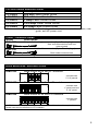
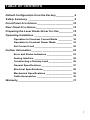
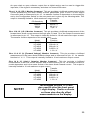
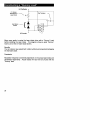
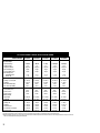
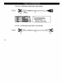
TM LFI 4500 Series Laser Diode Drivers User’s Guide 2 LFI-4500 Laser Diode Driver User’s Guide Publication number 92-130004D © Copyright 1996, 1997, Wavelength Electronics, Inc. P O Box 865, Bozeman, MT 59771 All Rights Reserved Printed in U. S. A. 3 Laser Diode Drivers The 4500 series of laser diode drivers offers an unprecedented combination of safety, performance, and value. Low noise, stable operation makes these flexible instruments ideal for even the most demanding applications. Any combination of LFI modules (both laser diode drivers and temperature controllers) can be interconnected to provide a complete laser diode control solution. Extensive protection features are incorporated into the 4500 series to protect your laser diode from damage. The output control circuitry includes a shorting relay which protects the laser diode when the output is off or the unit is powered down. The slow start circuit waits three seconds and then safely ramps the output to the preset operating level. To prevent thermal damage to your laser diode, the LFI-4500 series output can be disabled by the LFI-3500 temperature controller via the analog interface input. A unique AC power monitor circuit disables the output if AC power is above or below the recommended input level. Simple to use front panel controls make the 4500 series easy to operate. Highly visible LEDs indicate errors that effect the output, on/off status, and current limit condition. Control the laser diode forward current or monitor photodiode current using the linear ten-turn potentiometer. The current limit setting is fully independent and is set using a twelve-turn trimpot on the front panel. Interlock any combination of LFI-4500 series laser diode drivers or LFI-3500 series temperature controllers without additional hardware. Two or more modules mount into a 19" rack with optional rack mount kits KEY FEATURES ... • • • • • • • Low noise, stable current source (<20 ppm) Constant Current and Constant Power control modes Five models deliver from below 200mA to 6.5 Amps Works with all LD/PD configurations Easy to adjust, fully independent current limit Slow turn-on and comprehensive laser protection circuitry Operates on standard AC voltages ... the WAVELENGTH Advantage Low cost, flexible instrument Easy setup- Intuitive front and rear panels Display laser diode current and voltage, limit current, photodiode current Select photodiode range & modulation range for greatest sensitivity Four Selectable output filters allow maximum performance in CW or modulated mode Interface to the LFI 3500 Temperature Controller to protect laser diode from thermal runaway conditions Comprehensive Analog Interface includes: Buffered monitors: LD current & voltage, PD current, and LIMIT current Remote output ON/OFF control External control of operating current "Open Drain" ON/OFF and error status outputs Laser safety interlock 4 LFI 4500 Series Selection Guide Model Description LFI-4502 LFI-4505 LFI-4510 LFI-4532 LFI-4565 200 mA Laser Diode Driver 500 mA Laser Diode Driver 1 Amp Laser Diode Driver 3.25 Amp Laser Diode Driver 6.5 Amp Laser Diode Driver Each model includes: 9&15 pin D-sub plugs with shielded covers and hardware, user guide, and AC power cord. Cable – Selection Guide Model Description Output cable, single connector (9 pin D-sub plug) CAL-105 One end connectorized one end unterminated CAL-106 Output cable, double connector (9 pin D-sub plugs) Both ends connectorized All cables are 1 meter long. Rack Mount Kits- Selection Guide Model Description Rack mount kit for two LFI modules RMK-502 Includes two 5 1/4" panels RMK-503 Rack mount kit for three LFI modules Includes one 1" panel and one 5 1/4" panel RMK-504 Rack mount kit for four LFI modules Includes two 1" panels All RMK kits include (4)- 1/4-20 screws. No additional hardware is required to attach rack mount brackets to LFI modules. 5 Default Configuration from the Factory The following are the factory default settings. Rear Panel: CONFIGURATION SWITCH: OFF 1 2 3 4 5 6 7 8 9 10 ON CONFIGURATION Mode of Operation: Constant Current Modulation Bandwidth: Fully limited PD Current Range: 2000 µA Modulation Sensitivity: 10:1 Modulation Input: Disabled Front Panel: Current Limit: 6 25 mA for LFI-4502 50 mA for LFI-4505 100 mA for LFI-4510 250 mA for LFI-4532 & LFI-4565 TABLE OF CONTENTS Default Configuration from the Factory____________6 Safety Summary ______________________________8 Front Panel At a Glance _______________________10 Rear Panel At a Glance ________________________12 Preparing the Laser Diode Driver for Use _________15 Operating Guidelines _________________________16 Operation in Constant Current Mode __________ 16 Operation in Constant Power Mode ___________ 19 Set Current Limit ___________________________ 22 Further Information ___________________________23 Error and Status Indicators __________________ 23 Analog Interface ___________________________ 24 Constructing a Dummy Load _________________ 26 General Specifications ______________________ 27 Electrical Specifications_____________________ 28 Mechanical Specifications ___________________ 29 Cable Accessories _________________________ 30 Warranty ____________________________________31 7 Safety Summary Do not install substitute parts or perform any unauthorized modification to the product. Return the product to Wavelength Electronics for service and repair to ensure that safety features are maintained. Do not use this product beyond its specifications. SYMBOL DEFINITION OF SYMBOL WARNING Calls attention to a procedure, practice, or condition that could possibly cause bodily injury or death. ! ATTENTION Ce symbole signale une procédure ou des conditions dangereuses pouvant entraîner des blessures corporelles ou la mort. VORSICHT! Nichtbeachtung der Hinweise können die körperliche Unversehrtheit beeinträchtigen oder zum Tod führen. NOTE! Calls attention to a procedure, practice, or condition that could possibly cause damage to equipment or devices being operated by this equipment. CAUTION Risk of Electric Shock ATTENTION Risque d’Electrocution VORSICHT Hochspannung Earth Ground Symbol Chassis Ground Symbol 8 NOTE! Complete all operational steps in the order provided. Skipping a step can result in damage to the laser diode. Start with the section appropriate to the mode of operation you are using. WARNING For continued protection against fire, replace line fuse only with fuse specified, type and rating. ! ATTENTION Pour une protection permanente contre les risques d’incendie, ne remplacer les fusibles secteur que par des fusibles conformes aux spécifications. VORSICHT Defekte Sicherungen sind nur durch die angegeben Typen und mit den spezifizierten Werten zu ersetzen um die Sicherheit des Gerätes zu gewährleisten. CAUTION RISK OF ELECTRICAL SHOCK. Do not power on this instrument if the case is damaged or any of the covers or panels are removed. NO USER SERVICEABLE PARTS INSIDE. ATTENTION Risque d’Electrocution. Ne pas mettre sous tension cet instrument si le boîtier est endommagé ou si les capots ou les faces sont retirés. Aucun composant réparable par l’utilisateur. VORSICHT Hochspannung. Im Falle eines Gerätedefektes oder bei geöffneter Verkleidung Netzstecker ziehen! Gerät kann und braucht vom Anwender nicht gewartet werden. CAUTION POSSIBLE ELECTRICAL SHOCK OR FIRE HAZARD. Do not expose the LFI Laser Diode Driver to rain or moisture. Do not operate this instrument in the presence of flammable gases or fumes. ATTENTION Risque d’électrocution ou d’incendie. Ne pas exposer l’alimentation LFI à la pluie ou à l’humidité. Ne pas utiliser cet instrument en présence de gaz inflammable ou de fumée. VORSICHT Brandgefahr und Gefahr eines elektrischen Schocks! Setzen Sie das Gerät nicht dem Regen oder der Feuchtigkeit aus. Schalten Sie das Gerät in der Gegenwart entflammbarer Gase oder Dämpfe nicht ein! 9 Output Section: Output Enable Button: This switch enables and disables the laser diode current source output. When first enabled, the output current goes through a slow-start sequence. The slow start will delay the output of current for three seconds then slowly ramp the output current (approximately 500 ms) to the preset output current setting. While disabled, the LFI 4500 driver protects the laser diode by 1) shorting the laser diode with a relay, 2) taking the setpoint to zero, and 3) bringing the limit current to a low standby current. The relay will also short the laser diode when the unit is powered down. If an error occurs that shuts off the output, this button must be pressed once to clear the error and again to enable the current. Output On LED: This LED lights green whenever the output is enabled and current flows through the laser diode. Adjust Potentiometer: This ten-turn linear potentiometer is provided to adjust the Output Setpoint for either constant current or constant power mode. This potentiometer adjusts laser diode forward current in constant current mode and monitor photodiode current in constant power mode. Limit Current LED: This LED lights red whenever the laser diode output current is limited to the adjustment set by the Limit Current Trimpot. The output current will remain in this state until the setpoint is reduced below the Limit Current Trimpot setting. This condition does not create an error to shut the output off. Limit Current Trimpot: This trimpot adjusts the maximum current that can be delivered to the laser diode. Adjusting the trimpot clockwise increases the Limit Current Setpoint. Display Section: 3 1/2 Digit Display: This can be used to measure the laser diode forward current, the monitor photodiode current, the actual limit current and limit current setpoint, and the laser diode forward voltage. Display Select Switch: The position of this switch determines what value is displayed on the 3 1/2 digit LED display. 2000µ µA and 200µ µA PD I: To display the monitor photodiode current, the switch is set to one of these two positions. The switch position should be coordinated with the monitor photodiode current setting on the Configuration Switch on the rear panel for maximum resolution. To display the setpoint in constant power mode, rotate the Display Select Switch to the appropriate position and hold in the Display Set Button. LD I: This position displays the amount of current being sourced through the laser diode with these resolutions: LIMIT I MONITOR: This position displays the actual Limit Current flowing through the Limit Current Source. LIMIT I SETPOINT: This position displays the preset Limit Current Setpoint as set by the Limit Current Trimpot. LD V: This position displays the voltage across the laser diode load. 11 Rear Panel At A Glance The following terms for the rear panel components will be referenced throughout this manual. Analog Input Serial Number 6B4A1001 Output Connector Analog Interface Connector Configuration Switch Bank AC Fuse Voltage Select Switch AC Power Input Output Connector Description 9 pin D-sub recp Pin 1: Not Used 5 1 Pins 2 & 3: (Indicator -, Indicator+) These pins source 5 mA to an external LED indicating the output is on. Pins 4 & 5: (PD Anode, PD Cathode) These pins connect to the 9 OUTPUT 6 monitor photodiode. A monitor photodiode must be connected to operate the laser diode driver in constant power mode. Pins 6 & 9: (Laser Diode Anode) These two pins are jumpered for contact reliability and increased current capacity. Use both pins for best performance. Pins 7 & 8: (Laser Diode Cathode) These two pins are jumpered for contact reliability and increased current capacity. Use both pins for best performance. 12 Configuration Switch Bank: This ten position switch bank configures the mode of operation (constant current or constant power), the bandwidth of the output current, the range of photodiode sensitivity, and the modulation transfer function. Switches 1, & 2: (Constant Current or Constant Power Mode of Operation One of these switches must be on for proper operation. The following chart shows the positions for both modes of operation: Mode Switch 1 Switch 2 Constant Current ON OFF Constant Power OFF ON If both switches are accidentally left OFF, the output current will be shunted around the laser diode by the output control shunt MOSFETs. NOTE! If both switches are accidentally left ON, it is possible that the laser diode forward current could reach the Limit Current Setting. Switches 3, 4, & 5: (330µ µF, 10µ µF, 1µ µF filter capacitors) These switches select the type of capacitive filtering across the laser diode load. All or none of these switches can be ON at one time depending on the noise filtering and bandwidth requirements of the laser diode application. A minimum of 0.1µF capacitance is always present across the laser diode. The output current bandwidth will depend on the total output capacitance and impedance of the laser diode load. Switch 6: (Modulation Bandwidth) When this switch in ON, a single pole filter with a 3dB break frequency of 32Hz is inserted into the path of the setpoint control signal for the output control loop. This limits the bandwidth of the modulation signal to a frequency of less than 32Hz. This is extremely useful for very low noise applications such as spectroscopy and interferometry. Switches 7 & 8: (2000µ µA or 200µ µA Photodiode Current Sensitivity) This switch can configure the photodiode transimpedance amplifier’s sensitivity. The following table shows the available settings. Sensitivity Range Switch 7 Switch 8 ON OFF 50 - 2000µA OFF ON 15 - 200 µA OFF OFF 1 - 20 µA To increase the range to 20mA, set the switch for the 2000µA range and place a 10Ω resistor across pins 5 and 6 of the Output Connector. Switch 9: (Modulation Sensitivity) The modulation sensitivity can be controlled by this switch position. The following table details the transfer functions for each model: Switch 10: (Modulation Input Enable) This switch is used to enable or disable the modulation input. When this switch is OFF, the modulation input is disabled and the output cannot be controlled from the BNC or the Analog Interface Connector. When this switch is ON, the modulation input is enabled and the output can be controlled by these external analog inputs. 13 Analog Interface Connector: ANALOG INPUT 50 Ω Terminator 8 1 15 9 BNC & 15 pin D-sub receptacle ANALOG INTERFACE Pins 1 & 2: (Analog Input+, Analog Input-) External analog input. The BNC is in parallel, but isolated by two 1kΩ resistors. Either of the inputs can be used, but not simultaneously. Pins 3 & 4: (Interlock+, Interlock-) These pins must be shorted to turn the output on. The interlock is required by the FDA 21 CFR section 1040.10 and 1040.11 for operation of Class IIIB and IV lasers. The laser diode current output cannot be enabled if these pins are not shorted (the resistance between pins must be less than 5kΩ). Pins 5 & 6: (Error+, Error-) Connect to LFI-3500 temperature controller. If the temperature controller is disabled for any reason, the laser diode driver output will be disabled. Pin 7: (Error Detect) Error status. Pin 8: (On/Off Detect) On/Off status. Pin 9: (Common) Common for pins 7, 8, & 10 . Pin 10: (Remote On/Off) Remote On/Off control input. Pin 11: (PD I) Photodiode current monitor. Pin 12: (LD I) Laser Diode current monitor. Pin 13: (Forward Voltage- Vf ) Monitors voltage across laser diode Pin 14: (Limit I) Limit current monitor. Pin 15: (Monitor Common) Common for pins 11-14. 14 Preparing the Laser Diode Driver for Use Check the list of supplied items: o o o o o þ One Power cord One 9 pin D-Sub plug (solder cup), hood, and connecting hardware One 15 pin D-Sub plug (solder cup), hood, and connecting hardware One AC Fuse installed One AC Fuse is shipped separately This user’s Guide Verify that the correct power-line fuse is installed and the power-line voltage setting is correct. The factory sets the following defaults based on the country of destination for initial shipment: Destination Voltage Setting Fuse Rating US, Canada UK Continental Europe Japan 115V 230V 230V 115V 2A 1A 1A 2A For operation between 100 and 120VAC, install a 2 Amp slo-blow 5 x 20 mm fuse. Set the Voltage Select Switch to 115. For operation between 220 and 240V operation, install a 1 Amp slo-blow 5 x 20 mm fuse. Set the Voltage Select Switch to 230. 15 Step 4: Select the Modulation Input Bandwidth When only DC control of the output is necessary, the noise performance can be maximized by applying a single pole filter to the setpoint signal (the sum of the Adjust Potentiometer and Modulation Input). This filter is inserted when Switch 6 is ON. OFF OFF 1 2 3 4 5 6 7 8 9 10 1 2 3 4 5 6 7 8 9 10 ON ON High Bandwidth Mode CONFIGURATION Low Bandwidth Mode CONFIGURATION Step 5: Select the Photodiode Range If you connect a photodiode while in constant current mode, it will not be used in the feedback loop, but you can monitor the photodiode current to determine the laser diode power. For maximum sensitivity, three ranges of sensing are provided. If your photodiode maximum current exceeds 200µA, use the wider range. OFF 1 2 3 4 5 6 7 8 9 10 ON Max PD current 2000µA OFF OFF 1 2 3 4 5 6 7 8 9 10 ON 1 2 3 4 5 6 7 8 9 10 ON Max PD current 200µA Max PD current 20µA To increase the range to 20mA, set the switch for the 2000µA range and place a 10 Ω resistor across pins 5 & 6 of the Output Connector. Step 6: Select the Modulation Sensitivity & Enable or Disable Modulation The sensitivity selection is provided to maximize modulation performance. The modulation signal can be passed through as a 1:1 signal or attenuated by a 10:1 factor. The following details the modulation transfer functions for each model. Transfer Functions Switch 9 Switch 9 MODEL ON OFF LFI-4502 40mA / V 4 mA / V LFI-4505 100 mA / V 10 mA / V LFI-4510 200 mA / V 20 mA / V LFI-4532 0.650 A / V 0.065 A / V LFI-4565 1.3 A / V 0.13 A / V OFF 1 2 3 4 5 6 7 8 9 10 1:1 modulation range with modulation enabled. ON CONFIGURATION Switch 10 either enables or disables modulation. Modulation is disabled when Switch 10 is OFF. It is enabled when Switch 10 is ON. 17 Step 4: Select the Modulation Input Bandwidth When only DC control of the output is necessary, the noise performance can be maximized by applying a single pole filter to the setpoint signal (the sum of the Adjust Potentiometer and Modulation Input). This filter is inserted when Switch 6 is ON. OFF OFF 1 2 3 4 5 6 7 8 9 10 1 2 3 4 5 6 7 8 9 10 ON ON High Bandwidth Mode CONFIGURATION Low Bandwidth Mode CONFIGURATION Step 5: Select the Photodiode Range You must have a monitor photodiode to operate in constant power mode. For maximum sensitivity, two ranges of sensing are provided. If your photodiode maximum current exceeds 200µA, use the wider range. OFF OFF 1 2 3 4 5 6 7 8 9 10 ON OFF 1 2 3 4 5 6 7 8 9 10 ON Max PD current 2000µA 1 2 3 4 5 6 7 8 9 10 ON Max PD current 200µA Max PD current 20µA To increase the range to 20mA, set the switch for the 2000µA range and place a 10 Ω resistor across pins 5 & 6 of the Output Connector. Step 6: Select the Modulation Sensitivity & Enable or Disable Modulation The sensitivity selection is provided to maximize modulation performance. The modulation signal can be passed through as a 1:1 signal or attenuated by a 10:1 factor. The following details the modulation transfer functions for constant power mode. PD Range 2000 µA Range 200 µA Range Transfer Functions Switch 9 Switch 9 ON OFF 400 µA / V 40 µA / V 40 µA / V 4 µA / V OFF 1 2 3 4 5 6 7 8 9 10 1:1 modulation with modulation enabled ON CONFIGURATION Switch 10 either enables or disables modulation. Modulation is disabled when Switch 10 is OFF. It is enabled when Switch 10 is ON. 20 Error and Status Indicators Several LED indicators and a beeper are used to determine the status of the controller. Status Section Power LED: This LED lights green whenever the AC Power Switch on the front panel is depressed and AC power is supplied to the unit. Remote Error LED: This LED lights red whenever an error triggered by an LFI-3500 Temperature Controller is detected on the Analog Interface Connector on the rear panel. The output current is automatically switched off when a Remote Error condition occurs. Once the error is corrected, the Output On Button must be pressed once to clear the error and again to enable the output. Open Circuit LED: This LED lights red whenever the voltage measured across the laser diode exceeds the compliance voltage for the driver. This condition can occur if the impedance of the laser diode load is too high for the amount of current being sourced through the device or if the laser diode load is disconnected from the output connector. The output current is automatically switched off when an Open Circuit condition occurs. Once the error is corrected, the Output On Button must be pressed once to clear the error and again to enable the output. Interlock / Keylock Error LED: This LED lights red whenever the interlock connection is opened on the Analog Interface Connector on the rear panel, or when the Key Switch is rotated to the disabled position. The output current is automatically switched off when this error occurs. Once the error is corrected, the Output On Button must be pressed once to clear the error and again to enable the output. Output Section On LED: This LED lights green whenever the Output On Button is toggled on. This LED indicates that the output is now active and current will flow through the output connector. Limit LED: This LED lights red whenever the laser diode forward current is limited to the adjustment setting on the Limit Current Trimpot (see page 22). The output current will remain in this condition until the laser diode current falls below the Limit Current Trimpot setting. This condition does not switch the output current off. Beeper: The LFI beeps once whenever the output is turned on or off. 23 Analog Interface Pins 1 & 2: (Mod+, Mod-) An external analog signal can be directly connected to these pins (or the Analog BNC input) to remotely control the unit’s output current setpoint (Laser diode forward current in constant current mode and monitor photodiode current in constant power mode). This input is configured to accept ± 10 V signals while withstanding inputs as large as ± 40V. Any input on these pins is directly summed with the Output Current setpoint determined by the Adjust Potentiometer. The impedance of this input is 60kΩ as measured across these terminals. A total of 30kΩ isolates these inputs from pins 2 and 3 (LED Laser ON indicator) on the Output Connector. NOTE! If the laser diode is earth grounded only the Analog Input BNC may be used to modulate the laser diode. The shield side of the Analog BNC input is chassis grounded. Depending on how the laser diode is grounded, three options are available: 1. If the modulation inputs are not used, install the 50 Ω terminator (provided with the unit) and set the rear panel Configuration Switch positions 9 & 10 to OFF. 2. If the laser diode is not earth grounded, remove the 50 Ω BNC terminator and set the Configuration Switch Position 10 to ON and 9 to the appropriate modulation sensitivity. The signal can be input through either the Analog Input BNC or the Analog Interface Connector. 3. Only the Analog Input BNC may be used for modulating the laser diode when the laser diode is earth grounded. Remove the 50 Ω BNC terminator, replace it with the modulation source, and set the Configuration Switch Position 10 to ON and 9 to the appropriate modulation sensitivity. Pins 3 & 4: (Interlock+, Interlock-) These pins can be either shorted or connected to a remote interlock as required by the FDA 21 CFR, Section 1040.10 and 1040.11 for operation of Class IIIB and IV lasers. The impedance between pins 3 and 4 must be less then 5kΩ for the interlock and keylock functions to operate correctly. Pins 5 & 6: (Error+, Error-) These inputs were designed to connect to the LFI-3500 series temperature controllers. Complementary outputs on the temperature controller are located on the LFI-3500 analog interface connector. When these pins are connected to the LFI3500 temperature controller, if the temperature controller output is turned off (either by the Output On Button or any error), the LFI-4500 laser diode driver output will be disabled. These inputs require a minimum of 1.5 mA to trigger correctly. Three LFI-4500 laser diode drivers can be connected to any one LFI-3500 simultaneously. This input is optically isolated from the laser diode driver electronics. NOTE! LFI-4500’s output will NOT be disabled if the LFI-3500 is in its powered off state via its AC Power Switch. Pins 7 & 9: (Error Detect, Common) This output is an open drain connection that remains in a high impedance state while the output is enabled. If an error occurs that disables the output, this output is forced into a low impedance state with respect to the common connection (pin 9). Pins 8 & 9: (On/Off Detect, Common) This pin is an open drain connection that remains in a high impedance state when the output is disabled. When the output is enabled, this output is forced into a low impedance state with respect to the common connection (pin 9). Pins 9 & 10: (Common, Remote On/Off) These pins can be used to enable and disable the output current source and directly effect the front panel Output On LED. A normally open momentary switch with switch bounce less than 500 msec can be connected to these pins. 24 An open drain or open collector output from a digital section can be used to trigger this input also, if the signal is momentary and does not exceed 500 msec. Pins 11 & 15: (PD I, Monitor Common) This pin provides a buffered measurement of the current produced by the laser diode’s monitor photodiode (pins 4 and 5 on the Output Connector) and is referenced to pin 15. Its transfer function is dependent on the sensitivity set by the Configuration Switch on the rear panel and is given by the following table. This output is internally limited to 10mA maximum output current. Transfer PD Sensitivity Function 2000µA 400µA / V 200µA 40 µA / V 20µA 4 µA / V Pins 12 & 15: (LD I, Monitor Common) This pin provides a buffered measurement of the forward laser diode current sourced through pins 6,9 and 7,8 of the Output Connector and is referenced to pin 15. This output is internally limited to 10 mA maximum output current. The transfer function depends on the model used: Transfer Model Function LFI-4502 40 mA / V LFI-4505 100 mA / V LFI-4510 200 mA / V LFI-4532 0.650 A / V LFI-4565 1.3 A / V Pins 13 & 15: (Vf [Forward Voltage], Monitor Common) This pin provides a buffered measurement of the laser diode forward voltage and is referenced to pin 15. Its transfer function is 1 V / V. This output is internally limited to 10 mA maximum output current. Pins 14 & 15: (Limit I Setpoint, Monitor Common) This pin provides a buffered measurement of the limit current setpoint and is referenced to pin 15. Its transfer function is model dependent and is the same as that of the laser diode forward current. This output is internally limited to 10 mA maximum output current. Transfer Model Function LFI-4502 40 mA / V LFI-4505 100 mA / V LFI-4510 200 mA / V LFI-4532 0.650 A / V LFI-4565 1.3 A / V NOTE! The voltages on pins 11-15 are also used to drive the front panel 3 ½ digit display. Faults or shorts on these pins directly effect measurements on the display. 25 LFI 4500 General Specifications Power Supply: 115 or 230 VAC ±15% 50 or 60 Hz (switch selectable on rear panel) Maximum AC Input: 250VAC Power Consumption: 160VA Peak Size (W x D x H) 106 mm x 300 mm x 163 mm (4.25" x 12" x 6.5") Weight 4.5 kg (10 lb.) Operating Temperature: 0 to ≤ 40°C Storage Environment: − 40 to +70°C EMI and Safety: CE Compliant 27 LFI-4500 ELECTRICAL SPECIFICATIONS Model Number Drive Current Output Output Current Range Compliance Voltage Temperature Coefficient Short Term Stability (1 hr) Long Term Stability (24 hrs.) Noise and Ripple (rms) High Bandwidth Mode CW Mode Œ Photodiode Feedback PDI Range 1 (20 mA max.) • PDI Range 2 Max. forward PD Bias voltage Const. Power Output Stability External Analog Modulation Input Impedance (0-10 V) Transfer Function 1 Transfer Function 2 Bandwidth (3 dB) Ž High Bandwidth CW Mode Œ Display PDI Range 1 • PDI Range 2 Laser Diode Current LD Limit Monitor & Limit Setpoint LD forward voltage LFI-4502 LFI-4505 LFI-4510 LFI-4532 LFI-4565 0 - 200 mA > 4.3 V < 100 ppm/°C < 20 ppm < 50 ppm 0 - 500 mA >4V < 100 ppm/°C < 20 ppm < 50 ppm 0 - 1 Amp > 3.7 V < 100 ppm/°C < 20 ppm < 50 ppm 0 - 3.25 Amps > 3.6 V < 100 ppm/°C < 20 ppm < 50 ppm 0 - 6.5 Amps > 3.3 V < 100 ppm/°C < 20 ppm < 50 ppm < 5 µA < 1 µA < 8 µA < 1 µA < 10 µA < 3 µA < 15 µA < 5 µA < 20 µA < 5 µA 50 - 2000 µA 15 - 200 µA 0.200 V < 0.02 % 50 - 2000 µA 15 - 200 µA 0.200 V < 0.02 % 50 - 2000 µA 15 - 200 µA 0.200 V < 0.02 % 50 - 2000 µA 15 - 200 µA 0.200 V < 0.02 % 50 - 2000 µA 15 - 200 µA 0.200 V < 0.02 % 60 kΩ 40 mA/V 4 mA/V 60 kΩ 100 mA/V 10 mA/V 60 kΩ 200 mA/V 20 mA/V 60 kΩ 650 mA/V 65 mA/V 60 kΩ 1300 mA/V 130 mA/V DC -200 kHz DC - 32 Hz DC - 200 kHz DC - 32 Hz DC - 200 kHz DC - 32 Hz DC - 200 kHz DC - 32 Hz DC - 50 kHz DC - 32 Hz 0 - 1999 µA 0 - 199.9 µA 0 - 199.9 mA 0 - 199.9 mA 9.99 V max 0 - 1999 µA 0 - 199.9 µA 0 - 500 mA 0 - 500 mA 9.99 V max 0 - 1999 µA 0 - 199.9 µA 0 - 1.000 A 0 - 1.000 A 9.99 V max 0 - 1999 µA 0 - 199.9 µA 0 - 3.25 A 0 - 3.25 A 9.99 V max 0 - 1999 µA 0 - 199.9 µA 0 - 6.50 A 0 - 6.50 A 9.99 V max Œ Measured with maximum noise filtering on configuration switch. • The maximum photodiode range can be increased to 20 mA. Set the unit to the 2000 µA range and place a 10 Ω resistor across pins 5 & 6 on the output connector. Ž Modulation bandwidth is dependent on limit current setting and output load impedance. Bandwidth specifications are measured at maximum limit current setting and half maximum output current with a laser diode load. Simulated laser diode loads may produce varied results 28 MECHANICAL SPECIFICATIONS 29 WARRANTY If you have any questions or comments, please call our technical staff at (406) 587-4910. Our hours are 8:00 a.m. to 5:00 p.m. MT. Wavelength warrants the LFI 4500 Series laser diode drivers controllers for one year against defects in materials and workmanship when used within published specifications. This warranty extends only to purchaser and not to users of purchaser’s product. If Wavelength receives written notice of such defects during the warranty period, we will either repair or replace products which prove to be defective. It is purchaser’s responsibility to determine the suitability of the products ordered for its own use. Wavelength makes no warranty concerning the fitness or suitability of its products for a particular use or purpose; therefore, purchaser should thoroughly test any product and independently conclude its satisfactory performance in purchaser’s application. No other warranty exists either expressed or implied, and consequential damages are specifically excluded. The remedies provided herein are the Buyer’s sole and exclusive remedies. All products returned must be accompanied by a Return Material Authorization (RMA) number obtained from the Customer Service Department. Returned product will not be accepted for credit or replacement without our permission. Transportation charges or postage must be prepaid. All returned products must show invoice number and date and reason for return. The information contained within this document is subject to change without notice. Wavelength Electronics makes no warranty of any kind with regard to this material, including, but not limited to, the implied warranties of merchantability and fitness for a particular purpose. No part of this document may be photocopied, reproduced, or translated to another language without the prior written consent of Wavelength Electronics. PHONE (406) 587-4910 FAX (406) 587-4911 email: [email protected] P O BOX 865, BOZEMAN, MT 59771 31