1
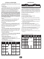
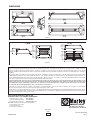
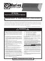
M Series
Fixed Overhead Radiant Heaters
Installation & Maintenance Instructions
Dear Owner,
Congratulations! Thank you for purchasing this new heater by Marley Engineered Products. You have made a wise investment selecting the highest quality product in the heating industry. Please carefully read the installation and maintenance
instructions shown in this manual. You should enjoy years of efficient heating comfort with this product from Marley
Engineered Products... the industry’s leader in design, manufacturing, quality and service.
... The Employees of Marley Engineered Products
!
WARNING
Read Carefully - These instructions are written to help you prevent
difficulties that might arise during installation of heaters. Studying
the instructions first may save you considerable time and money
later. Observe the following procedures and cut your installation
time to a minimum. Failure to follow these instructions may lead to
fire, electric shock, personal injury, property damage or product failure.
1. This radiant heater is a component of the complete heating system. The heating system designer must consider the risks associated with its operation and specify adequate controls and safety devices. Where the consequences of failure could result in
personal injury, property damage or fire, back-up controls are
essential.
2. Read all instructions before using the heater.
3. Do NOT use this heater as a residential or household heater.
4. This heater is hot when in use. To avoid burns, do not let bare
skin touch hot surfaces. If used as a portable heater, keep combustible materials, such as furniture and papers at least 5 feet
from the front of the heater.
5. Always disconnect the heater when not in use.
6. To prevent possible electrical shock, disconnect ALL power
coming to heater at main service panel before wiring or
servicing.
7. All wiring must be in accordance with the National and Local
Electrical Codes and the heater must be grounded as a
precaution against possible electrical shock.
8. Verify the power supply voltage coming to the heater matches
the ratings printed on the heater nameplate before energizing.
9. This heater is NOT suitable for use in hazardous locations as
described by the National Fire Protection Association (NFPA).
This heater has hot and arcing or sparking parts inside. DO NOT
use in areas where gasoline, paint or other flammable liquids are
used or stored.
10. In order to prevent fire, electric shock, injury to persons and
equipment damage, protect with a ground fault device (GFCI or
GFI) such as Marley Engineered Products WMGF240 for 240V
heaters and WMGF480 for 480 volt heaters.
11. This heater is intended for Ceiling Installation ONLY (except as
noted below.). The following clearances MUST be maintained:
a)
Top of heater to ceiling - 24" (640 mm)
b)
Bottom of heater to floor - 10' (3048 mm)
c)
Side of heater to wall - 36" (914 mm)
d)
End of heater to wall - 36" (914 mm)
e)
Side of heater to side of adjacent heater - 36" (914 mm)
f)
End of heater to end of adjacent heater - 36" (914 mm)
12. Heater MUST be securely fastened to the building structure to
prevent it from falling.
13. DO NOT stack or store combustible materials in the radiation
path under the heater, or in the space a distance of 5 feet from
any projected edge of the heater.
14. Under special controlled conditions this heater may be
converted for use as a movable heater by installation of the
optional Portable Cart Kit, Cord Kits, Grille Kit and Tip Over Kits.
Extreme care must be taken when using this heater as a
movable unit! The heater operates at very high
temperatures and could cause a fire if placed too close to
combustible materials. NEVER OPERATE THIS HEATER AS
A MOVABLE UNIT WHILE UNATTENDED. Always maintain at
least the minimum clearances as stated above. If the Tip Over
Kit is not provided, the heater could cause a fire if it falls over.
15. If used as a cord connected movable heater, always make sure
the outlet or power source to which the heater is connected is
properly grounded. Use of the heater with an extension cord is
not recommended. If one must be used, it must be provided
with a grounding conductor and must be rated to handle a load
of at least 125% of the maximum heater ampere load. Always
inspect the cord for damage before each use and do not use if
damaged. Route cord so it is not subject to being damaged
during use.
16. Use this heater only as described in this manual. Any other use
not recommended by the manufacturer may cause fire, electric
shock or injury to persons.
SAVE THESE INSTRUCTIONS
INSTALLATION
The Marley Engineered Products radiant heater is shipped
fully assembled. The heater can be hung from the ceiling with 4
chains or rigid angle brackets attached to the heater brackets
located on the back of the heater, for 2 and 4.5 kW heaters,
chains can be attached to the four holes in the corners of the back
reflector. Optional hanging chain kits are available for these
heaters that will allow for installations 2 to 6 feet from the ceiling.
(Model MHK) (See Figure 1.) Minimum spacings:
Ceiling to top of heater is 2 feet.
Wall to sides of heater is 3 feet.
Floor to bottom of heater is 10 feet.
NOTE: Installer should consult state and local codes and meet
any applicable requirements regarding this installation.
WARNING
!
!
Wall
1. Use heater only at the voltage specified on the nameplate.
2. Branch circuit wire for connection to heater must be at least
90°C wire. Use copper conductors only.
3. Heater can be wired with rigid or flexible conduit.
4. Refer to Table 1 for proper supply wiring size.
5. The heater connection points are located in the gasketed
terminal enclosure. To remove cover, remove 4 screws on the
cover. Remove the cover to expose wiring connection points.
6. A green ground terminal is provided in the bottom of the
enclosure. The ground wire should be connected before other
connections are made.
7. Attach power to pigtail leads L1 and L2 (or L1, L2 & L3 on 3
phase models) using appropriate listed connectors.
NOTE: All 3 element heaters are factory pre-wired for 3-phase
delta operation. Some units can be converted to single phase
operation by changing the wiring. Refer to Table 1 for those
heaters that can be converted to single phase. The appropriate
wiring diagram (Figure 2) is also located on the bottom of the
enclosure.
a
5' min
(1524mm)
INSTRUCTIONS FOR FIELD CONVERSION
FOR 3 PHASE TO 1 PHASE
5' min
(1524mm)
Heater
1. Remove nuts from all terminals.
2. Remove all pigtail leads and hat shaped buss bar.
3. Remove end of lead wire on terminal 5 and slip onto
terminal 4.
4. Remove lead wire attached to instruction sheet and connect
between terminals 4 and 6.
5. Install hat shaped buss bar between terminals 3 and 5.
6. Place pigtail lead marked “L1” on to terminal 2 and pigtail lead
marked “L2” on to terminal 6.
7. Install nuts and tighten.
8. Connect entrance wiring to pigtail leads “L1” and “L2”. Connect
ground to screw provided.
9. Inspect to make sure wiring is per “Single Phase Wiring”
above.
3' (914.4mm) Min.
TOP VIEW
3' (914.4mm) Min.
No Storage Area
5' min
(1524mm)
Ceiling
Chain
2' (609.6mm) Min.
Wall
Figure 1
SIDE VIEW
10' (3048mm) Min.
Area must be
kept clear of
combustible
materials
Floor - Non-combustible surface
WIRING
!
WARNING
a
FIRE HAZARD. Electric radiant heaters operate at very high
temperaures and many factors determine element life. At end of
life a radiant element in many instances will passively open circuit, however it is possible to have an arc failure that will result
in molten metal falling from the heater. To prevent personal
injury from molten metal, element damage and fire, Ground
Fault Equitment Protection must be provided.
FIRE HAZARD. Radiant heaters are capable of developing
high temperatures, care should be taken to:
A. Mount heater with the proper clearance between heater and
walls, ceiling and floor. B. Mount heater in horizontal position
only. Do not mount vertically or tilted in any direction. C. Do not
mount heater over combustible surfaces. D. Do not stack or
store combustible materials directly below the heater or in the
space a distance of 5 feet from any projected edge of the
heater. E. Do not operate the heater without Ground Fault
Equipment protection. Failure to follow these instructions can
result in personal injury and fire.
Wall
WARNING
a
ELECTRIC SHOCK HAZARD. Disconnect all power before
installing or servicing heater. Failure to do so could result in
personal injury or property damage. Heater must be effectively
grounded in accordance with the National Electrical Code,
NFPA 70.
All electrical wiring must be done by a qualified person in
accordance with National Electrical Code (NEC) and meet all
state and local regulations.
Figure 2
2
OPTIONAL ACCESSORIES
MAINTENANCE
Marley Engineered Product M series radiant heaters can be
field modified by adding optional kits. Refer to Figure 3 to select
the proper kit.
The heater requires no special maintenance other than occasional cleaning to prevent excess accumulation of dust and lint on
surfaces. It is important for the reflectors to be kept clean to
obtain the maximum radiant output. If used as a movable unit, the
cart and cord should be checked periodically to make sure the
hardware remains tight and cart and cord are not damaged. Do
not continue to use the heater if damaged.
Element Replacement
1. Remove Terminal Box Cover.
2. Disconnect lead wires from heater terminals.
3. Remove safety grills (if installed).
4. Remove retainer screw located on the reflector at the terminal
end.
5. Loosen (2), 3/8" nuts from the terminal box bracket located on
the back of the heater and slide the entire heating element
assembly out of the reflector assembly.
6. Remove wires and jumper straps as required to replace the
failed heating element(s).
7. Remove bulkhead fitting nuts and washers.
8. Remove failed element and replace with a new element.
Replace only with genuine "Arctic End" elements. Use of
other elements will cause excess temperatures inside terminal
box.
9. Place gasket on the bulkhead fitting and insert terminals and
fittings into the element holes in the terminal box.
10. Place washers and nuts on bulkhead fittings and tighten.
11. Replace wiring and jumper straps.
12. Reassemble by following the reverse procedures (steps 5
through 1).
Grill Kit
The grill kit consists of one (1.5, 2, 4.5 and 6 kW) or 2 grill
sections (13.5kW) and hardware to protect personnel from
coming into contact with hot radiant heating elements.
See instruction sheet 5200-2646-var for details.
Disconnect Kit
The disconnect kit consists of a complete assembly consisting
of a disconnect switch (3 Pole), power terminal block and all
hardware to complete the installation. This kit can be mounted to
both the fixed, overhead heater or the portable heater;
see instruction sheet 5200-2652-var for details.
Hanger Kit
Hanger kit model MHK include 24 feet of chain and four S
hooks to mount the unit in a fixed overhead position using the
universal mounting brackets included on the heater. This kit
allows installation distances from the ceiling of 2 feet to 6 feet.
See installation diagram Fig. 1 on page 2.
Cord Kits (Portable Only)
Cord kits consist of 25 feet of 90°C cable and a right angle
cord fitting which can connect directly to the heater terminal box
or disconnect switch (if used). See instruction sheet
5200-2647-var for details
Table 1 – HEATER SELECTION CHART
Tip Over and Ground Fault Kits
TOS240 Series Kit attaches to portable heater and deenergizes the heater in the event it is tipped over.
WMGF240 Series Kit mounts to wall that de-energizes heater
prior to element failure.
See instruction sheet 5200-2652-var.
Model
M2081B
M2021B
M2041B
M2061B
M4581B
M4521B
M4541B
M4561B
M6083B
M6023B
M6071B
M6043B
M6063B
M13583B
M13523B
M13571B
M13543B
M13563B
Grill
Kit
Disconnect
Kit
WG2
WG45
PDS60050
PDS60050
WG60
WG135
Wall Mount
Ground Fault
Notify Factory
WMGF240
WMGF480
Notify Factory
Notify Factory
WMGF240
WMGF480
Notify Factory
Notify Factory
WMGF240
Notify Factory
WMGF480
Notify Factory
Notify Factory
WMGF240
Notify Factory
WMGF480
Notify Factory
Model
M2081B
M2021B
M2041B
M2061B
M4581B
M4521B
M4541B
M4561B
M6083B
M6023B
M6071B
M6043B
M6063B
M13583B
M13523B
M13571B
M13543B
M13563B
Portable
Cart Kit**
NA
M45
M60
M135
Note: Order model MHK Hanging Kit to mount M Series and N Series
infrared heaters. This kit comes complete with chain and hooks.
a
ELECTRIC SHOCK HAZARD. Disconnect all power before
servicing or replacing heating elements.
Portable Cart Kit
The portable cart kit can be used to convert a fixed overhead
unit into a portable heating device where a fixed installation is not
required. This kit includes wheels, legs, handle, grill(s), baffle (if
req'd) and all of the necessary hardware to complete the
modification. See instruction sheet 5200-2648-var. for details.
“CAUTION - Use of this kit presents certain hazards
including risks for fire or burns. Extreme care must be taken
when use of any Marley Engineered Products heater with this
kit. See Warnings in front of this manual for additional
details. As an added safety precaution, we strongly recommend the Tip Over Kit and Grille Kit be used in conjunction
with the Portable Cart Kit. It will help reduce the risk of fire
if the heater and cart happen to fall over or if something happens to fall against the heater.”
Figure 3 – Optional Accessory Selection Guide
WARNING
!
3
Watts Volts
208
2000 240
480
600
208
4500 240
480
600
208
240
6000 240
480
600
208
240
13500 277
480
600
Phase
Reflector Element
Angle
Type
Ship
Wt.
1
18 lbs.
1
18 lbs.
1&3
1&3
1
1&3
1&3
3
3
1
1&3
1&3
Metal
90˚ Symm
m
Sheath
25 lbs.
55 lbs.
Avail.
NS
S
NS
NS
NS
S
S
NS
NS
S
NS
S
NS
NS
S
NS
S
NS
Wire Ga. (Min.)
1 Ph
3 Ph
14
NA
14
NA
14
NA
14
NA
12
NA
12
NA
14
NA
14
NA
10
12
10
12
10
12
12
12
12
NR
10
NR
10
8
12
12
12
12
DIMENSIONS
2.0 kW
4.5 kW
33-1/4”
33-1/4”
844.55 mm
20-7/16”
207/16”
519.11mm
6-5/16”
65/16”
134.94mm
11-1/2”
111/2”
292.1mm
99-1/2”
1/2”
241.3mm
SIDE VIEW
5555-3/4
3/4””
1416.05mm
SIDE VIEW
1-1/2”
11/2”
38.1mm
11-9/16”
119/16”
293.69mm
1515-1/2
1/2””
393.7mm
TOP VIEW
15-1/2”
151/2”
393.7mm
FRONT VIEW
Figure 3
FRONT VIEW
6.0 kW
13.5 kW
11-1/2"
(292.1mm)
11-1/2"
(292.1mm)
23-5/8"
(600.08mm)
23-5/8"
(600.08mm)
32-1/2"
(825.5mm)
Figure 4
55-5/8"
(1412.88mm)
LIMITED WARRANTY
All products manufactured by Marley Engineered Products are warranted against defects in workmanship and materials for one year from date of installation. This warranty does not apply to damage from accident, misuse, or alteration; nor where the connected voltage is more than 5% above the nameplate voltage; nor to equipment
improperly installed or wired or maintained in violation of the product’s installation instructions. All claims for warranty
work must be accompanied by proof of the date of
1
installation.
The customer shall be responsible for all costs incurred in the removal or reinstallation of products, including labor costs, and shipping costs incurred to return products
to Marley Engineered Products Service Center. Within the limitations of this warranty, inoperative units should be returned to the nearest Marley authorized service center or the Marley Engineered Products Service Center, and we will repair or replace, at our option, at no charge to you with return freight paid by Marley. It is agreed that
such repair or replacement is the exclusive remedy available from Marley Engineered Products.
THE ABOVE WARRANTIES ARE IN LIEU OF ALL OTHER WARRANTIES EXPRESSED OR IMPLIED, AND ALL IMPLIED WARRANTIES OF MERCHANTABILITY AND
FITNESS FOR A PARTICULAR PURPOSE WHICH EXCEED THE AFORESAID EXPRESSED WARRANTIES ARE HEREBY DISCLAIMED AND EXCLUDED FROM
THIS AGREEMENT. MARLEY ENGINEERED PRODUCTS SHALL NOT BE LIABLE FOR CONSEQUENTIAL DAMAGES ARISING WITH RESPECT TO THE PRODUCT, WHETHER BASED UPON NEGLIGENCE, TORT, STRICT LIABILITY, OR CONTRACT.
Some states do not allow the exclusion or limitation of incidental or consequential damages, so the above exclusion or limitation may not apply to you. This warranty
gives you specific legal rights, and you may also have other rights which vary from state to state.
For the address of your nearest authorized service center, contact Marley Engineered Products in Bennettsville, SC, at 1-800-642-4328. Merchandise returned to the factory must be accompanied by a return authorization and service identification tag, both available from Marley Engineered Products. When requesting return authorization, include all catalog numbers shown on the products.
HOW TO OBTAIN WARRANTY SERVICE AND
WARRANTY PARTS PLUS GENERAL INFORMATION
1. Warranty Service or Parts
2. Purchase Replacement Parts
3. General Product Information
1-800-642-4328
1-800-654-3545
www.marleymep.com
Note: When obtaining service always have the following:
1. Model number of the product
2. Date of manufacture
3. Part number or description
5200-2645-003
ECR 38575
12/09
4
470 Beauty Spot Rd. East
Bennettsville, SC 29512 USA
Part #161-305343-002
Rev. 2