1
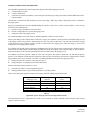
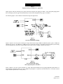
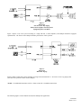
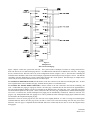
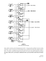
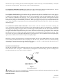
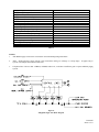
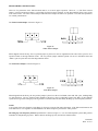
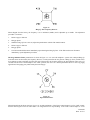
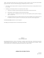
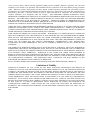
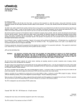
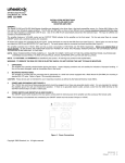
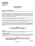
273 Branchport Avenue
Long Branch, NJ 07740
(800) 631-2148
www.wheelockinc.com
Thank you for using our products.
INSTALLATION INSTRUCTIONS
MODEL TPI-100
TELEPHONE PAGING RING START INTERFACE
Use this product according to this instruction manual. Please keep this instruction manual for future reference.
APPLICATION INFORMATION:
Wheelock Inc. manufactures high quality telephone products. The installation of this product must conform to the following
instructions. IF ANY WORDS OR LETTERS APPEAR ON THE PRODUCT INDICATING A PARTICULAR USE, THE PRODUCT
MUST BE USED ONLY IN THE MANNER SO INDICATED. THE INSTALLATION OF THIS EQUIPMENT SHOULD ONLY BE
UNDERTAKEN BY QUALIFIED PERSONNEL. FIELD ADJUSTMENT, REPAIR OR MODIFICATION OF THESE SIGNALS SHOULD
NOT BE ATTEMPTED. Malfunctioning units should be returned for factory repair or replacement in accordance with Wheelock
Inc.'s published terms and conditions. Contact Wheelock Inc., 273 Branchport Ave., Long Branch, NJ, 07740.
NOTE: All CAUTIONS and WARNINGS are identified by the symbol
. All warnings are printed in bold capital letters.
FCC REGULATIONS
-
-
This equipment complies with Part 68 of the FCC Rules. The label affixed to this product contains, among other
information, the FCC Registration Number and the Ringer Equivalence Number (REN) for this product. This information
must be provided to the telephone company if requested.
The REN is used to determine the quantity of devices which you may connect to your telephone line and still have all of
those devices ring when your telephone number is called. In most, but not all areas, the sum of the REN's of all devices
connected to one line should not exceed five (5.0). To be certain of the number of devices that you may connect to your
line, contact your local telephone company.
This equipment should not be used on coin telephone lines. Connection to party line service is subject to state tariffs.
If trouble is experienced, disconnect this equipment from the telephone line to determine if it is causing the malfunction. If
the equipment is determined to be malfunctioning, its use shall be discontinued until the problem has been corrected.
Should the equipment cause harm to the telephone network, the telephone company shall, if possible, notify the customer
that temporary discontinuance of service may be required; however, where prior written notice is not possible, the
telephone company may temporarily discontinue service without notice, if such action is necessary under the
circumstances. The telephone company may make changes in its communication facilities, equipment and operations
procedures, where such action is reasonably required in the operation of its business and is not inconsistent with the rules
and regulations of the Federal Communications Commission.
INDUSTRY CANADA REGULATIONS
NOTICE: The Industry Canada label identifies certified equipment. This certification means that the equipment meets
-
-
certain telecommunications network protective operational and safety requirements. The Department does not guarantee
the equipment will operate to the user's satisfaction.
Before installing this equipment, users should ensure that it is permissible to be connected to the facilities of the local
telecommunications company. The equipment must also be installed using an acceptable method of connection. In some
cases, the company's inside wiring associated with a single line individual service may be extended by means of a certified
connector assembly (telephone extension cord). The customer should be aware that compliance with the above conditions
may not prevent degradation of service in some situations.
Any repairs or alterations made by the user to this equipment, or equipment malfunctions, may give the
telecommunications company cause to request the user to disconnect the equipment.
Make sure that the electrical ground connections of the power utility, telephone lines and internal metallic water pipe
system, if present, are connected together.
CAUTION: The installation of this equipment should only be undertaken by qualified personnel.
The Load Number (LN) assigned to each terminal device denotes the percentage of the total load to be connected to a
telephone loop which is used by the device, to prevent overloading. The termination on a loop may consist of any
combination of devices subject only to the requirement that the total of the Load Numbers of all the devices does not
exceed 100.
Load Number for TPI-100 = 8
P82030 K
Sheet 1 of 17
GENERAL APPLICATION INFORMATION:
The Telephone Paging Interface (TPI-100) provides ring start (90V/20Hz) paging access from:
A.
B.
C.
A Central Office (CO) line.
A Centrex number line.
A station level position on telephone systems which provide analog ring voltage (90V/20Hz), and 600 OHM audio to their
extension phones.
The TPI-100 is a ring detector that monitors the line for ring voltage. When ring voltage is detected, the caller is connected to
the paging system.
Paging is accomplished by touch tone (DTMF) dialing the CO line, Centrex line, or station extension number. After one ring,
the TPI-100 will simultaneously:
A.
B.
C.
Generate a single Confirmation Tone to the caller.
Generate a single Page Alert Tone to the paging system.
Connect the caller to the paging system.
The Confirmation/Page Alert Tone volume is internally adjustable, and has an "Off" position.
When a caller hangs up the telephone at the conclusion of a page, some telephone systems generate an immediate Hang Up Tone
to the paging system, some generate a delayed Hang Up Tone, while others remain silent. The TPI-100 can interface a paging
system with all of these telephone systems, because it will disconnect the paging system before the Hang Up Tone can be
transmitted over the paging system speakers.
For telephone systems that generate a delayed or immediate Hang Up Tone, the TPI-100 is equipped with a variable Frequency
Detector (200 to 950Hz) which is adjusted during installation to detect the telephone system's specific Hang Up Tone frequency.
When that frequency is detected on Tip and Ring, the TPI-100 will disconnect the paging system.
For telephone systems that generate a Hang Up Tone with a frequency that cannot be detected by the TPI-100's Frequency
Detector, or for telephone systems that do not generate a Hang Up Tone (remain silent), the TPI-100 is equipped with a variable
Page Duration Timer (3 to 51 seconds). The timer is set during installation to disconnect the paging system by:
A.
B.
Timing out before the occurrence of the Hang Up Tone or…
Simply timing out, for telephone systems that remain silent.
Whenever the Tone Frequency Detector is used:
A.
B.
It will take precedence over the Page Duration Timer.
The Page Duration Timer is placed in the maximum (51 seconds) position.
Chart 1 shows the proper application of the Tone Frequency Detector and the Page Duration Timer.
Telephone System
"Hang Up" Tone
Immediate
Delayed
Cannot be detected by
Frequency Detector
None (Silent)
Tone Frequency
Detector
Yes
Yes
Page Duration
Timer
Yes
Yes
No
No
Yes
Yes
Chart 1.
Application of Tone Frequency Detector and Page Duration Timer
The Page Duration Timer is programmed for "VOX" (Voice Operated) or "MAN." (Manual) control using the Timer Control
Jumper, as shown in Chart 2.
Position of Timer Control Jumper for:
Position of
P82030 K
Sheet 2 of 17
Telephone "Hang Up" Tone
Immediate
Delayed
None (Silent)
Not Detectable by Frequency
Detector
Immediate
Delayed
One-Way
Paging
VOX
VOX
VOX
MAN.
VOX
Talkback
Paging
VOX
VOX
MAN.
MAN.
MAN.
One-Way Paging
Using FZC-3 Zone Control
VOX
VOX
MAN.
MAN.
MAN.
Tone Detect
Jumper
EN.
EN.
DIS.
DIS.
DIS.
Chart 2.
Timer Control Jumper and Tone Detect Jumper Settings
FOR ONE-WAY PAGING, The Timer Control Jumper is placed in the "VOX" position. This allows the TPI-100 to sense the
presence of audio on Tip and Ring, thereby delaying the Page Duration Timer as long as audio is present within the preset time.
If audio is not present for the preset time, then the TPI-100 will disconnect the paging system when the preset time has elapsed,
or the Hang Up Tone is detected, whichever occurs first.
FOR PAGING WITH TALKBACK, If the telephone system generates a Hang Up Tone that can be detected by the Tone
Frequency Detector, then the Timer Control Jumper is placed in the "VOX" position. This allows the TPI-100 to sense the
presence of audio, even after the caller hangs up, because the talkback speaker is still placing audio on the line. As a result, the
Page Duration Timer is continually delayed. Only the detection of the Hang Up Tone will disconnect the paging system.
If the telephone system generates a Hang Up Tone that cannot be detected by the Tone Frequency Detector, or if the telephone
system does not generate a Hang Up Tone (remains silent), then the Timer Control Jumper is placed in the "MAN" position.
The preset time is absolute, and the TPI-100 will disconnect the paging system when the preset time has elapsed.
NOTE:
Voice signals of the same frequency as the Hang Up Tone may cause the TPI-100 to disconnect. If the TPI-100 disconnects due
to the detection of voice signals, it is recommended that the Timer Control Jumper and Tone Detect Jumpers be placed using the
“Not Detectable by Frequency Detector” setting per Chart 2.
NOTE:
Telephone lines with less than -15dBM (0.1VRMS) audio level, could result in insufficient gain to operate talkback paging
systems.
MUSIC INPUT, The TPI-100 also provides a music input that is muted during a page. At the conclusion of the page, the
music is restored to the system.
TYPES OF PAGING SYSTEMS, The TPI-100 can be connected to the following types of paging systems:
A.
SINGLE ZONE PAGING:
1.
2.
3.
B.
Amplified speakers and horns for one-way paging, or...
A central paging amplifier and speakers/horns equipped with 25V/70V line matching transformers, for one-way
paging, or…
A Wheelock amplified talkback speaker (TBM-101) or horn (TBH-104) system, for paging with talkback.
MULTI ZONE PAGING:
Up to 3 zones of paging when used with Wheelock Fixed Zone Control (FZC-3).
1.
Items A1 and A2 above can be mixed in the same system.
SINGLE OR MULTIPLE LINE PAGING: The TPI-100 can be used in single line paging applications, or several can be
interconnected for multiple line paging applications.
In single line applications, a ring start line is dedicated to paging and connected to a TPI-100.
In multiple line applications, a TPI-100 and a ring start line are dedicated to each paging zone, each zone group, and "All Call"
paging. Interconnected TPI-100's automatically establish paging priorities as shown in Chart 3.
Type of Page
Priority
All Call
1
Zone Group
2
P82030 K
Sheet 3 of 17
Zone
3
Chart 3.
Paging Priorities for Multiple Line Applications
Higher priority TPI-100's interrupt lower priority TPI-100's and place their paging on "Hold". If the interrupted paging phone
does not Hang Up, then the page will automatically be restored when the higher priority page is concluded.
The following Figures 1 thru 4 illustrate and describe single line applications.
Figure 1.
Single Line
One Zone with Talkback Paging
Figure 1 depicts a one zone system consisting of a single TPI-100 and a single TBM-101 talkback speaker system, or TBH-104
talkback horn system. One TBM-101 or TBH-104 may be used with a TPI-100. Depending upon the telephone systems Hang
Up Tone characteristics, the Timer Control Jumper can be in the "VOX" or "MAN." position. See Chart 2.
Figure 2.
Single Line
One Zone, One-Way Paging
With Amplified Speakers and Horns
Figure 2 depicts a one zone system consisting of a single TPI-100 and multiple one-way paging amplified speakers/horns. If
more than three amplified speakers are used, a PRM-150 preamplifier is required to boost the audio level. The Timer Control
Jumper should be placed in the "VOX" position.
P82030 K
Sheet 4 of 17
Figure 3.
Single Line
One Zone, One-Way Paging
With Central Amplifier and Transformer
Equipped Speakers and Horns
Figure 3 depicts a one zone system consisting of a single TPI-100, a central amplifier, and multiple transformer equipped
speakers/horns. The Timer Control Jumper should be placed in the "VOX" position.
Figure 4.
Single Line
Multi Zone Paging
Figure 4 depicts a multi zone system consisting of a single TPI-100 and an FZC-3. All zones are one-way paging zones.
(See Chart 2 for position of Timer Control Jumper.)
*NOTE: For additional information on FZC-3 Units see the FZC-3 installation instructions.
The following Figures 5 and 6 illustrate and describe multiple line applications.
P82030 K
Sheet 5 of 17
Figure 5.
Multiple Lines
Zone and All Call Paging
Figure 5 depicts a multi zone system with "All Call". The system consists of multiple CO/Centrex or analog extension lines.
Each zone line has its own TPI-100 and page devices. An additional line and TPI-100 are dedicated to "All Call". The paging
devices connected to the TPI-100's can be any of the configurations shown in Figure 1 thru 4. The TPI-100's controlling the
individual zones should have their Timer Control Jumper programmed as described previously in Figures 1 thru 4. The TPI-100
controlling "All Call" should have its Timer Control Jumper placed in the "VOX" position. Note that single, or multiple music
sources may be used, because each TPI-100 has its own music input.
TO ACCESS AN INDIVIDUAL ZONE, dial the number of the line connected to the TPI-100 controlling that zone. An alert
tone is signaled to the zone to announce the page, and back into the phone as a confirmation tone.
TO ACCESS ALL ZONES SIMULTANEOUSLY, dial the number of the line connected to the TPI-100 controlling "All
Call". If individual zone paging is in progress when an "All Call" page is initiated, then an Alert Tone will be signaled back to
the zone paging telephones and they will be put on "Hold" for the duration of the "All Call" page. Also, a page alert tone signal
will be heard at all speakers in the system. At the conclusion of the "All Call" page, telephone still on "Hold" (did not hang up)
will receive a reconnect tone, and the interrupted zone paging will be automatically reconnected. When an "All Call" is in
progress, any attempted individual zone paging access will be prohibited, and an interrupted ringing signal (unanswered call)
will be heard in the telephone attempting to page.
When FZC-3 Units are used as page devices, the "All Call" occurs slightly different. If a FZC-3 is being accessed through an
individual TPI-100, and an "All Call" page occurs, the FZC-3 will be reset so that the incoming "All Call" may select zones.
When the "All Call" page is completed and the individual TPI-100 is reconnected, the user must re-access the original zone(s)
being paged.
P82030 K
Sheet 6 of 17
Figure 6.
Multiple Lines
Zone, Group and All Call Paging
Figure 6 depicts a multi zone system with group page and "All Call". The system consists of multiple CO/Centrex or analog
extension lines. Each zone line has its own TPI-100 and page devices. An additional line and TPI-100 is assigned to each page
group, and to "All Call". The paging devices connected to the TPI-100's can be any of the configurations shown in Figures 1
thru 4. The TPI-100's controlling the individual zones should have their Timer Control Jumper programmed as described
previously, in Figures 1 thru 4. The TPI-100's controlling group page or "All Call" should have their Timer Control Jumper
placed in the "VOX" position. Note that single or multiple music sources may be used, because each TPI-100 has its own music
input.
P82030 K
Sheet 7 of 17
There are three ways of accessing the zones with this configuration. First the zones may be accessed individually. Second, the
zones may be accessed in groups. Third, all zones can be accessed simultaneously.
TO ACCESS AN INDIVIDUAL ZONE, dial the number of the line connected to the TPI-100 controlling that zone. An alert
tone is signaled to the zone to announce the page and back into the phone as a confirmation tone.
TO ACCESS A ZONE GROUP, dial the number of the line connected to the TPI-100 controlling that zone group. An alert
tone is signaled to all zones in the group to announce the page and back into the phone as a confirmation tone. If zone paging is
in progress when a group page is initiated, then an alert tone will be signaled back to the zone page telephones and they will be
put on "Hold" for the duration of the group page. Also, a page alert tone signal will be heard at all zone speakers within the
group. At the conclusion of the group page, telephone still on "Hold" (did not hang up) will receive a reconnect tone, and the
interrupted zone paging will be automatically reconnected. When a group page is in progress, any attempted individual zone
access within the group will be prohibited and an interrupted ringing signal (unanswered call) will be heard in the telephone
attempting to page.
TO ACCESS ALL ZONES SIMULTANEOUSLY, dial the number of the line connected to the TPI-100 controlling "All
Call". An alert tone is signaled to all zones to announce the page and back into the phone as a confirmation tone. If individual
zone paging or group paging is in progress when an "All Call" page is initiated, then an alert tone will be signaled back to the
zone and/or group paging telephones and they will be put on “Hold” for the duration of the "All Call" page. Also, a page alert
tone signal will be heard at all speakers in the system. At the conclusion of the "All Call" page, telephones still on "Hold" (did
not hang up) will receive a reconnect tone, and the interrupted group, or Zone Paging will be automatically reconnected. When
an "All Call" is in progress, any attempted individual zone or group paging access will be prohibited, and an interrupted ringing
signal (unanswered call) will be heard in the telephone attempting to page.
When FZC-3 Units are used as page devices, the "Group Page" and the "All Call" occurs slightly different. If a FZC-3 is being
accessed through an individual TPI-100 and a "Group Page" or "All Call" occurs, the FZC-3 will be reset so that the incoming
"Group Page" or "All Call" may select zones. When the "Group Page" or "All Call" is completed and the individual TPI-100 is
reconnected, the user must re-access the original zone(s) being paged.
MOUNTING INFORMATION:
The TPI-100 is designed for surface mounting. Remove the top cover by pushing on the latch at the bottom of the housing base
with a small screw driver. See Figure 7. To mount the base (containing the P.C. Board Assembly), space the 2 mounting screws
provided horizontally on 2.750" centers, also shown in Figure 7.
Figure 7.
Mounting Instructions
CAUTION: These devices are not intended for use in hazardous locations as defined by the National Electrical Code (NEC)
and by the National Fire Protection Association (NFPA).
SPECIFICATIONS:
P82030 K
Sheet 8 of 17
Supply Voltage (Nominal)
Supply Voltage Range
Supply Current (Idle - BGM)
Supply Current (Nominal - Page)
Supply Current (Max. - All/Group Page)
Alert Tone Frequency
Alert Tone Duration
Audio Input/Output Levels (Note 3)
Ring Voltage Input Level (Nominal)
Ring Voltage Input Operating Range
Audio Input and Output Impedance
Hang Up Tone Detect Frequency Range
Hang Up Tone Detect Time
Page Duration Timer Range
Operating Temperature Range
Operating Humidity Range
Ringer Equivalence (REN)
-24VDC
-21.6VDC TO -26.4VDC
64mA (See Note 1)
109mA
134mA (See Note 2)
680Hz +/-10%
450m Seconds +/-10%
-15dBM(0.1VRMS) to +10dBM (2.4VRMS)
90VAC/20Hz
40V-130V,20Hz-30Hz
600 OHMS
200hz to 950Hz
250m Seconds
3 to 51 Seconds
0 to 55 Degrees C
0 to 85%
0.5A
Chart 4.
NOTES:
1.
"Idle-BGM" supply current is the current draw when transmitting background music.
2.
"Max. - All/Group Page" supply current is the current draw during an “All Page” or “Group Page”. It applies only to
systems with multiple interconnected TPI-100's.
3.
Telephone lines with less than -15dBM (0.1VRMS) audio level, could have insufficient gain to operate talkback paging
systems.
Figure 8.
Simplified Single Line Block Diagram
P82030 K
Sheet 9 of 17
WIRING INSTRUCTIONS (SEE FIGURE 9):
CAUTION: Use class 2 power source only.
1.
Make sure 24VDC power supply is disconnected from the 115VAC power source.
2.
Connect Tip and Ring from the telephone line to TB2, terminals 8 and 7 respectively.
3.
Connect the background music source to TB2, terminals 3 and 4.
4.
In single line applications, connect the paging system devices to TB2, terminals 5 and 6.
5.
When connecting a TPI-100 to a FZC-3, refer to Figure 10.
6.
In multiple line applications with “All Call”:
7.
A.
Connect TB2 terminals 5 and 6 from the "All Call" TPI-100 to TB2 terminals 1 and 2 of all individual zone TPI100's.
B.
Connect TB1 terminal 6 from the "All Call" TPI-100 to TB1 terminal 4 of all individual zone TPI-100's
In multiple line applications with “Group Page” and “All Call”:
A.
Connect TB2 terminals 5 and 6 from each "Group Page" TPI-100 to TB2 terminals 1 and 2 of each individual zone
TPI-100 within the group.
B.
Connect TB1 terminal 6 from the "Group Page" TPI-100, to TB1 terminal 4 of each individual zone TPI-100 within
the group.
C.
Connect TB2 terminals 5 and 6 from the "All Call" TPI-100 to TB2 terminals 1 and 2 of all "Group Page" TPI-100's.
D.
Connect TB1 terminal 6 from the "All Call" TPI-100 to TB1 terminal 4 of all "Group Page" TPI-100's.
8.
Connect GND (+) and (-) from the 24VDC power supply to TB1 terminals 1 and 2 respectively.
9.
Connect the 24VDC power supply to the 115VAC power source.`
P82030 K
Sheet 10 of 17
Figure 9.
Installation Programming, and Tone
Volume Adjustment Diagram
P82030 K
Sheet 11 of 17
Figure 10.
Connection to FZC-3
NOTES:
1.
Set the FZC-3 “Talk Battery/TPI-100” selector switch to the “TPI-100” position.
2.
If TPI-100 and FZC-3 use separate power supplies, then install wire between GND (TB1, terminal 5) on TPI-100 and GND
(TB1, terminal 4) on FZC-3.
3.
For additional information on FZC-3 refer to its installation instructions.
P82030 K
Sheet 12 of 17
PROGRAMMING INSTRUCTIONS:
There are five parameters in the TPI-100 which must be set to insure proper operation. These are , (1) The Timer Control
Jumper, (2) The Tone Detector Jumper, (3) The Hang Up Tone Frequency Detector, (4) The Page Duration Timer, and. (5) The
Tone Alert Volume. The Timer Control Jumper and Tone Detect Jumper each have two positions. The other three parameters
are variable potentiometers.
The Timer Control Jumper is shown in Figure 11.
Figure 11.
Timer Control Jumper
When shipped from the factory, the two position jumper is placed over the two right-hand (center and "VOX") pins for voice
operated control of the Page Duration Timer. The two position jumper should be placed over the two left-hand (center and
"MAN.") pins for preset time out of the Page Duration Timer.
The Tone Detect Jumper is shown in Figure 12.
Figure 12.
Tone Detect Jumper
When shipped from the factory, the two-position jumper is placed over the two left-hand (center and “EN”) pins, enabling Hang
Up Tone detection. The two position jumper should be placed over the two right-hand (center and “DIS”) if the telephone
system does not generate a Hang Up Tone or generates a tone that cannot be detected by the Hang Up Tone Frequency Detector.
NOTE:
Voice signals of the same frequency as the Hang Up Tone may cause the TPI-100 to disconnect. If the TPI-100 disconnects due
to the detection of voice signals it recommended the Tone Detect Jumper be placed in the “DIS” position.
The Hang Up Tone Frequency Detector potentiometer is shown in Figure 13. It is used with telephone systems that generate
immediate or delayed Hang Up Tones. When it detects the Hang Up Tone, the TPI-100 will disconnect.
P82030 K
Sheet 13 of 17
Figure 13.
Hang Up Tone Frequency Detector
When shipped from the factory, the frequency is set to minimum (200Hz), and is adjustable up to 950Hz. The adjustment
procedure is as follows:
1.
Initiate a page to TPI-100.
2.
Hang up phone.
3.
When the Hang Up Tone comes on, adjust the potentiometer until the TPI-100 disconnects.
4.
Initiate a page to TPI-100
5.
Hang up phone.
6.
The TPI-100 should disconnect immediately upon detecting the Hang Up Tone. If the TPI-100 does not disconnect
immediately, repeat adjustment procedures.
The Page Duration Timer potentiometer is shown in Figure 14. It is used with telephone systems with a delayed Hang Up
Tone that cannot be detected by the frequency detector, or with systems that do not generate a Hang Up Tone (remain silent).
For telephone systems with Hang Up Tones that can be detected by the frequency detector, the Page Duration Timer (set at 51
seconds with its Timer Control Jumper in the "VOX" position) also serves as a back-up disconnect device in one-way paging
applications if the paging party inadvertently does not hang up.
Figure 14.
Page Duration Timer
When shipped from the factory the timer is set to 51 seconds (maximum). If the Timer Control Jumper is set for "VOX" control,
then the timer begins to time out when audio is no longer detected on Tip and Ring. If the Timer Control Jumper is set for
P82030 K
Sheet 14 of 17
"MAN." control, then the timer begins to time out when the page is initiated. Therefore "VOX" will provide variable duration
paging, while "MAN." will provide fixed duration paging. The adjustment procedure is as follows:
1.
If the Hang Up Tone Frequency Detector is being used to disconnect the TPI-100, then leave the Page Duration Timer set
for 51 seconds.
2.
If the Hang Up Tone Frequency Detector is not used, then proceed as follows:
A.
Using lines not connected to the TPI-100, dial station to station and have someone answer the call.
B.
Hang up phone, while the called party remains off hook (keep listening).
C.
After the caller hangs up, called party times how long it takes for the telephone system to generate its Hang Up,
"Dial" or "Reorder" tone.
D.
Set the Page Duration Timer for just under the amount of time it takes the telephone system to generate its tone. If
the telephone system does not generate a tone (remains silent), then set the timer to the desired page duration.
The Tone Alert Volume potentiometer is shown in Figure 15.
If the Hang Up Tone Frequency Detector is not used, then proceed as follows:
Figure 15.
Tone Alert Volume Control
When shipped from the factory, volume is set to maximum. To adjust the volume, initiate a page. Listen for the tone alert in the
telephone handset and at the paging speakers. If the volume is too high or too low, adjust potentiometer accordingly. The Page
Alert/Confirmation Tone can be turned off by placing the potentiometer in the "MIN." position.
OPERATING INSTRUCTIONS
P82030 K
Sheet 15 of 17
TPI-100 TELEPHONE/PAGING RING START INTERFACE
1.
Pick up the telephone handset and dial the line number assigned to the TPI-100. After one ring, the TPI-100
connects the caller to the paging system, and it will signal the caller back with a confirmation tone.
2.
If paging speakers are connected directly to the TPI-100 the caller may begin paging immediately after hearing
the confirmation tone. If a FZC-3 is connected to the TPI-100, the caller must dial a zone number after hearing
the confirmation tone. A second confirmation tone will be generated to the caller by the zone control, after
which the caller may begin paging.
3.
After the caller hangs up, the TPI-100 will disconnect when a Hang Up Tone is detected or when the Page
Duration Timer has timed out.
TROUBLE SHOOTING:
Condition
Check
1. TPI-100 cannot be accessed.
1. Check presence and polarity of voltage on (-) 24VDC
and (+) GND terminals.
2. Check presence of Tip and Ring.
3. Check All Call Input (ACI), All Call Output (ACO)
and Zone Control Output (ZCO) wiring.
4. Verify unit has released from last page.
2. No sound or low page
volume.
1. Check presence and level of audio input at Tip and
Ring terminals.
2. Number of one-way amplified speakers/horns
connected to the TPI-100 should not exceed three. If
more then three, install a PRM-150 pre-amplifier
between the output of the TPI-100 and the inputs of
the amplified speakers.
Limited Warranty
Wheelock products must be used within their published specifications and must be PROPERLY specified, applied, installed,
operated, maintained and operationally tested in accordance with these instructions at the time of installation and at least twice a
year or more often and in accordance with local, state and federal codes, regulations and laws. Specification, application,
installation, operation, maintenance and testing must be performed by qualified personnel for proper operation in accordance
with all of the latest National Fire Protection Association (NFPA), Underwriters' Laboratories (UL), Underwriters' Laboratories
of Canada (ULC), National Electrical Code (NEC), Occupational Safety and Health Administration (OSHA), local, state,
P82030 K
Sheet 16 of 17
county, province, district, federal and other applicable building and fire standards, guidelines, regulations, laws and codes
including, but not limited to, all appendices and amendments and the requirements of the local authority having jurisdiction
(AHJ). Wheelock products when properly specified, applied, installed, operated, maintained and operationally tested as
provided above are warranted against mechanical and electrical defects for a period of three years from date of manufacture (as
determined by date code). Correction of defects by repair or replacement shall be at Wheelock's sole discretion and shall
constitute fulfillment of all obligations under this warranty. THE FOREGOING LIMITED WARRANTY SHALL
IMMEDIATELY TERMINATE IN THE EVENT ANY PART NOT FURNISHED BY WHEELOCK IS INSTALLED IN THE
PRODUCT. THE FOREGOING LIMITED WARRANTY SPECIFICALLY EXCLUDES ANY SOFTWARE REQUIRED
FOR THE OPERATION OF OR INCLUDED IN A PRODUCT. WHEELOCK MAKES NO REPRESENTATION OR
WARRANTY OF ANY OTHER KIND, EXPRESS, IMPLIED OR STATUTORY WHETHER AS TO MERCHANTABILITY,
FITNESS FOR A PARTICULAR PURPOSE OR ANY OTHER MATTER.
USERS ARE SOLELY RESPONSIBLE FOR DETERMINING WHETHER A PRODUCT IS SUITABLE FOR THE USER'S
PURPOSES, OR WHETHER IT WILL ACHIEVE THE USER'S INTENDED RESULTS. THERE IS NO WARRANTY
AGAINST DAMAGE RESULTING FROM MISAPPLICATION, IMPROPER SPECIFICATION, ABUSE, ACCIDENT OR
OTHER OPERATING CONDITIONS BEYOND WHEELOCK'S CONTROL.
SOME WHEELOCK PRODUCTS CONTAIN SOFTWARE. WITH RESPECT TO THOSE PRODUCTS, WHEELOCK
DOES NOT WARRANTY THAT THE OPERATION OF THE SOFTWARE WILL BE UNINTERRUPTED OR ERRORFREE OR THAT THE SOFTWARE WILL MEET ANY OTHER STANDARD OF PERFORMANCE, OR THAT THE
FUNCTIONS OR PERFORMANCE OF THE SOFTWARE WILL MEET THE USER'S REQUIREMENTS. WHEELOCK
SHALL NOT BE LIABLE FOR ANY DELAYS, BREAKDOWNS, INTERRUPTIONS, LOSS, DESTRUCTION,
ALTERATION, OR OTHER PROBLEMS IN THE USE OF A PRODUCT ARISING OUT OF OR CAUSED BY THE
SOFTWARE.
THE LIABILITY OF WHEELOCK ARISING OUT OF THE SUPPLYING OF A PRODUCT, OR ITS USE, WHETHER ON
WARRANTIES, NEGLIGENCE, OR OTHERWISE, SHALL NOT IN ANY CASE EXCEED THE COST OF CORRECTING
DEFECTS AS STATED IN THE LIMITED WARRANTY AND UPON EXPIRATION OF THE WARRANTY PERIOD ALL
SUCH LIABILITY SHALL TERMINATE. WHEELOCK IS NOT LIABLE FOR LABOR COSTS INCURRED IN
REMOVAL, REINSTALLATION OR REPAIR OF THE PRODUCT BY ANYONE OTHER THAN WHEELOCK OR FOR
DAMAGE OF ANY TYPE WHATSOEVER, INCLUDING BUT NOT LIMITED TO, LOSS OF PROFIT OR INCIDENTAL
OR CONSEQUENTIAL DAMAGES. THE FOREGOING SHALL CONSTITUTE THE SOLE REMEDY OF THE
PURCHASER AND THE EXCLUSIVE LIABILITY OF WHEELOCK.
IN NO CASE WILL WHEELOCK'S LIABILITY EXCEED THE PURCHASE PRICE PAID FOR A PRODUCT.
Limitation of Liability
WHEELOCK'S LIABILITY ON ANY CLAIM OF ANY KIND, INCLUDING NEGLIGENCE AND BREACH OF
WARRANTY, FOR ANY LOSS OR DAMAGE RESULTING FROM, ARISING OUT OF, OR CONNECTED WITH THIS
CONTRACT, OR FROM THE MANUFACTURE, SALE, DELIVERY, RESALE, REPAIR OR USE OF ANY PRODUCT
COVERED BY THIS ORDER SHALL BE LIMITED TO THE PRICE APPLICABLE TO THE PRODUCT OR PART
THEREOF WHICH GIVES RISE TO THE CLAIM. WHEELOCK'S LIABILITY ON ANY CLAIM OF ANY KIND SHALL
CEASE IMMEDIATELY UPON THE INSTALLATION IN THE PRODUCT OF ANY PART NOT FURNISHED BY
WHEELOCK. IN NO EVENT SHALL WHEELOCK BE LIABLE FOR ANY CLAIM OF ANY KIND UNLESS IT IS
PROVEN THAT OUR PRODUCT WAS A DIRECT CAUSE OF SUCH CLAIM. FURTHER, IN NO EVENT, INCLUDING
IN THE CASE OF A CLAIM OF NEGLIGENCE, SHALL WHEELOCK BE LIABLE FOR INCIDENTAL OR
CONSEQUENTIAL DAMAGES. SOME STATES DO NOT ALLOW THE EXCLUSION OR LIMITATION OF
INCIDENTAL OR CONSEQUENTIAL DAMAGES, SO THE PRECEDING LIMITATION MAY NOT APPLY TO ALL
PURCHASERS.
3/99
P82030 K
Sheet 17 of 17