1
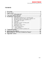
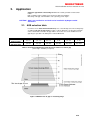
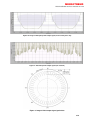
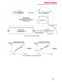
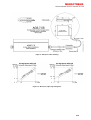
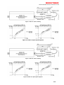
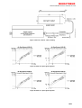
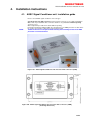
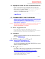
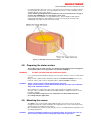
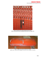
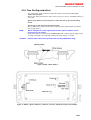
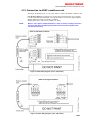
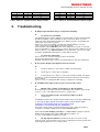
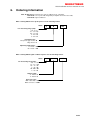
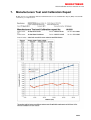
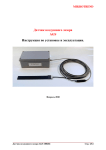
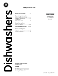
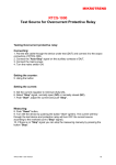
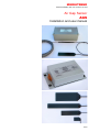
MIKROTREND
AGS Installation and user manual 141129
Air Gap Sensor
AGS
Installation and user manual
1/23
MIKROTREND
AGS Installation and user manual 141129
Contents
1. Overview ................................................................................... 3
2. Application................................................................................ 4
2.1. AGS selection table .......................................................................... 4
3. Technical specifications ......................................................... 6
4. Installation instructions ........................................................ 11
4.1.
4.2.
4.3.
4.4.
4.5.
4.6.
4.7.
4.8.
4.9.
4.10.
4.11.
4.12.
5.
6.
7.
8.
AGSC Signal Conditioner unit installation guide ............................ 11
Appropriate location for AGSC signal conditioner unit .................... 13
Grounding of AGSC signal conditioner unit .................................... 13
Power supply connection................................................................ 13
Calibration....................................................................................... 13
AGSP Sensor probe installation guide............................................ 13
Placing the sensor .......................................................................... 13
Preparing the stator surface............................................................ 14
Mounting the sensor ....................................................................... 14
True Air-Gap and offset ................................................................ 17
Cable installation .......................................................................... 18
Connection to AGSC conditioner unit ........................................... 19
Troubleshooting..................................................................... 20
Ordering information ............................................................. 21
Manufacturers Test and Calibration Report ........................ 22
Important notice ..................................................................... 23
2/23
MIKROTREND
AGS Installation and user manual 141129
THIS INSTRUCTION MANUAL SHOULD BE READ CAREFULLY
AND THE SAFETY INSTRUCTIONS OBSERVED BEFORE
INSTALLING, CALIBRATING OR USING THE EQUIPMENT
DESCRIBED HEREIN.
- Installation and maintenance must be performed by qualified personnel familiar with
the construction, operation, and hazards involved with the equipment.
- Installation and maintenance must be performed with the control out of operation
and disconnected from all sources of power
- Care should be taken when servicing electrostatic sensitive components. The
manufacturer’s recommendations for these components should be followed.
- Ventilation passages should be kept open.
- The means employed for grounding or insulating the equipment from ground should
be checked to assure its integrity.
- Care must be taken to avoid damaging any delicate components and to avoid
displacing dust, dirt, or debris in a way that permits it to enter or settle into parts of
the control equipment.
- Enclosures should be inspected for evidence of deterioration. Accumulated dust
and dirt should be removed from the top of the enclosures before opening doors or
removing covers.
1.
Overview
Air Gap Sensor (AGS) is high accuracy, non contact, capacitive type distance
measuring sensor for measuring air-gap in air-cooled generators and electric motors.
AGS is made of low profile sensor probe with triaxial cable, preamplifier and shielded
cable.
Our unique Edge Mount type for wind generators and electric motors with very small
air gap.
High stability carbon particle semiconductive electrode made from glass-epoxy fiber
(FR4).
DC/DC insulated power supply.
Optocoupler insulated output, 0…20 mA / 0...10V or 4...20mA / 2...10V.
Wide operating temperature range with +/-3% accuracy (Full Scale Deflection):
-Sensor probe: -20...140°C,
-Signal Conditioner: -20...50°C
Immune to magnetic fields, dust and oil vapours, EMI, RFI....
3/23
MIKROTREND
AGS Installation and user manual 141129
2.
Application
Capacitive type distance measuring sensor for air-cooled generators and electrical
motors.
High sensitivity, high resolution (up to 50 microns with oversampling).
Measuring of air-gap, rotor vibrations, rotor symmetry, power angle…
CAUTION: AGS is not certified for and shall not be installed in hydrogen-cooled
alternators.
2.1. AGS selection table
In order to ensure measurement headroom please select Air Gap Sensor measuring range
according to the true air gap range per Table 1. Given dimensions are absolute maximum
values. Actual value of the true air gap shall be selected as close to the middle of true air
gap range as possible. If in doubt please contact Mikrotrend.
Sensor type
Linear measuring
distance (mm)
Min / Max. true air
gap range (mm)
AGS-4S
AGS-7,5S
AGS-13
AGS-25
AGS-50
AGS-51
0,8...4
1,5... 7,5
2,6...13
5...25
10...50
5...50
1,7...4,9
2,7...8,7
3,8...14,2
8,3...28,3
13,3...53,3
8,3...53,3
Table 1. Linear measuring distance from the sensor surface vs. true air gap
(other ranges available per request)
Figure 1. Minimum true air gap vs. measuring range
4/23
MIKROTREND
AGS Installation and user manual 141129
Figure 1b: Image of AGS pole profile output signal, zoom of two poles only
Figure 2: AGS Pole profile output signal (one rotation)
Figure 3: Image of AGS output signal, polar data
5/23
MIKROTREND
AGS Installation and user manual 141129
3.
Technical specifications
Measuring range (mm)
(from sensor surface)
Linear measuring range (mm)
(from sensor surface)
Min / Max true air gap (mm)
Linearity FSD (25°C)
Linearity FSD (-20...50/80/125°C) (1)
Linearity FSD (-20...50/80/140°C) (2)
Output noise (% of FSD)
AGS-4S
AGS-7,5S
AGS-13
AGS-25
AGS-50
0...4
0...7,5
0...13
0...25
0,8...4
1,5...7,5
2,6...13
5...25
1,7...4,9
+/-1,5%
2,7...8,7
+/-1,5%
3,8...14,2
+/-1,5%
8,3...28,3
+/-1,5%
AGS-51
0...50
10...50
+/-3%
+/-3%
5...50
13,3...53
8,3...53
+/-3%
+/-5%
+/-5%
0,5%
0…20mA, (0mA=0mm), or 4...20mA (4mA=0mm)
with 500 Ohm termination resistor 0...10V (2...10V), opto-insulated
Sensitivity 0...20mA output
5mA/mm
2,667mA/mm
1,539mA/mm
0,8mA/mm
0,4mA/mm
Sensitivity 0...10V output
2,5V/mm
1,334V/mm
0,769V/mm
0,4V/mm
0,2V/mm
Sensitivity 4...20mA output
4mA/mm
2,134mA/mm
1,231mA/mm
0,64mA/mm
0,32mA/mm
Sensitivity 2...10V output
2V/mm
1,067V/mm
0,615V/mm
0,32V/mm
0,16V/mm
Typical frequency response
0...1000Hz, (-3dB) other bandwidth optional
Magnetic flux density withstand
+/-2 Tesla
Operating temp. (AGS probe)
-20...125°C or -20...140°C
Operating temp. (AGS preamp.)
-20...80°C
Operating temp. (AGS conditioner)
-20...50°C
Storage temperature (AGS conditioner)
-20...80°C
Power input
+24Vdc, ±10%, 0,15A max.
Warm-up time
approx. 20 min.
Relative humidity
95% non condensing
Vibration
IEC 68 2.27, 5 g peak, 10 Hz to 150 Hz
Shock
IEC 68 2.27, 15 g peak, 11ms
EMC
Sensor probe not affected by magnetic fields +/- 2 Tesla, 50/60 Hz
Probe immunity
magnetic fields, dust and oil vapours, without degradation of material
AGSP probe dimension (mm)
51x25x0,8
68x29x1,1
120x29x1,1
232x32x3,3
175x60x3,3
AGSP cable length (m)
0,8 or 1,8 + 10
AGSC sig. conditioner dimension (mm)
220 × 120 × 80 w/o cable inlets
AGSC sig. conditioner protection class
IP66
Weight AGS probe + cable
6g + 230g
10g + 230g
15g + 230g
50g + 250g
100g + 250g
Weight AGSC signal conditioner
1500g
(1) AGSC (signal conditioner) at 50°C, AGS (preamp.) at 80°C, AGS (probe) at 125°C
(2) AGSC (signal conditioner) at 50°C, AGS (preamp.) at 80°C, AGS (probe) at 140°C
Output pole profile
10
8
Voutput (V)
±3%
6
4
2
0
0
5
10
15
20
Linear measuring range
25
Air Gap (mm)
Figure 4. AGS-25 Linearity definition Full Scale Deflection (FSD)
6/23
MIKROTREND
AGS Installation and user manual 141129
Figure 5. AGS-4S outline drawing
Figure 5a. AGS-4S output signal diagrams
7/23
MIKROTREND
AGS Installation and user manual 141129
Figure 6. AGS-7,5S outline drawing
Figure 6a. AGS-7,5S output signal diagrams
8/23
MIKROTREND
AGS Installation and user manual 141129
Figure 7. AGS-13 outline drawing
Figure 7a. AGS-13 output signal diagrams
Figure 8. AGS-25 outline drawing
Figure 8a. AGS-25 output signal diagrams
9/23
MIKROTREND
AGS Installation and user manual 141129
Figure 9. AGS-50 / AGS-51 outline drawing
Figure 9a. AGS-50 output signal diagrams
Figure 9b. AGS-51 output signal diagrams
10/23
MIKROTREND
AGS Installation and user manual 141129
4.
Installation instructions
4.1. AGSC Signal Conditioner unit installation guide
Please select AGSC signal conditioner enclosure type:
NOTE:
a) Sealed enclosure with connectors, prefered enclosure type, use for Stator installation.
Water and oil proofed IP64 cable connectors allow for easy installation without opening
enclosure cover.
Offset adjustment possible from outside without opening.
Practical and simple installation within door and hinge box for EMC protection of cable wires.
No need to open and no replacement of desiccant needed.
Sealed enclosure must be placed inside auxiliary door and hinge enclosure for EMC
protection of connection wires.
Figure 10a. AGSC Signal Conditioner unit enclosure with connectors (CON)
Figure 10b. AGSC Signal Conditioner unit enclosure with connectors (CON),
(mounting dimensions)
11/23
MIKROTREND
AGS Installation and user manual 141129
b) Enclosure with cable inlets, use for Rotor mounted and stand alone installation where
no door and hinge enclosure is available for protection.
Cables can be installed with tight fitting, oil and water proofed up to IP64.
NOTE:
AGSC must be closed during operation, contains humidity sensitive circuits. Replace
desiccant after opening and allow at least 12h to dry-up before calibration and /or
measuring .
Figure 10c. AGS Signal Conditioner unit enclosure with cable inlets (CAB) (before S/N 144701)
Figure 10d. AGS Signal Conditioner unit enclosure with cable inlets (CAB) (after S/N 144701)
Figure 10d. AGS Signal Conditioner unit enclosure with cable inlets (CAB),
(mounting dimensions)
12/23
MIKROTREND
AGS Installation and user manual 141129
4.2. Appropriate location for AGSC Signal Conditioner unit
Distance up to 10 meters from the sensor probe (longer distance is possible, please
enquire), up to 200 meters from acquisition unit with 0...20mA loop. If voltage output is used,
interference free distance may vary, depending on type of wiring and nearby equipment
which my generate electromagnetic disturbance.
- Prefer well ventilated, dry area free of vibrations and stray magnetic fields,
- Ensure adequate grounding for enclosure with minimum lenght of wire,
- Ensure access to 24 VDC / 0,15A power supply.
NOTE:
When using enclosure with connectors auxiliary enclosure with door and hinge is
mandatory to shield AGSC signal conditioner wires from environmental influences,
for EMC protection etc.
4.3. Grounding of AGSC Signal Conditioner unit
CAUTION:
Grounding is essential for system operation integrity as well as for protection against
hazardous voltages. For best grounding, provide the shortest path possible between
the AGSC signal conditioner unit and the grounded structure.
Use flexible steel conduit to protect all cables from electromagnetic fields except
inside of stator winding where PVC conduit shall be used. Keep ample distance from
nearby power lines, ( see Figure 15b ).
WARNING:
MULTICORE CABLE SHIELD SHALL BE GROUNDED AT ACQUISITION CARD INPUT
ONLY. MULTIPLE GROUND POINTS WILL CAUSE NOISE PICK-UP AND CAN
DAMAGE CONDITIONER UNIT ELECTRONICS.
4.4. Power supply connection
Power to AGSC signal conditioner unit shall be 24VDC, ±10%, 0,15A max.
Conditioner unit input has insulated DC-DC converter allowing any pole to be grounded or
floating power supply as well as daisy chain of several Conditioner units.
4.5. Calibration
The AGSP sensor probe and AGSC signal conditioner units are factory matched and
calibrated for best performance. However if needed, may be calibrated at site. For details
please cantact www.mikrotrend.com
4.6. AGSP Sensor probe installation guide
CAUTION:
AGSP sensor probe shall be handled with care.
Do not apply paint or silicone to the sensor surface.
Never pull or use excessive force on the sensor cable or preamplifier.
The sensor surface is treated with high quality insulation varnish, it shall not be scrached as
damage to semiconductive electrodes may occur.
4.7. Placing the sensor
Choose position for AGSP sensor probe considering number of sensors and machine poles.
True acurate rotor/stator geometry can be obtained with only one Rotor mounted Air
Gap Sensors, and four Stator mounted Air Gap Sensors.
(http://www.mikrotrend.com/wrm-wireless-hydrogenerator-rotor-monitor.htm)
If Wireless Rotor AGS is not used than good practical results are achieved with:
-4 sensors per generator for diameters of less than 7,5 meters,
-8 sensors per generator with dimeter 7,5…12 meters
-and 12 to 16 sensorsr for larger diameters.
13/23
MIKROTREND
AGS Installation and user manual 141129
For vertical machines place the sensors on the upper side of the stator as it will have higher
excentricity than the lower side. For stator height of more than 1,8 meters Air Gap sensors
should be placed on the lower side also.
Sensor shall be glued against stator laminations as deep as practical in the air gap or
at stator edge if EDGE type of sensor probe is to be used.
In general, this is beneath the second ventilation hole. The preamplifier (small cylinder
shape integrated within the cable) must stay outside of the air gap and outside of the
endwindings, if possible outside of the stator casing.
Figure 11. Air Gap Sensor probe positions
4.8. Preparing the stator surface
Thoroughly clean the stator surface, use allowed cleaning liquid such as isopropanol
alcohol, disposable cotton rags and fine non-metallic sandpaper.
WARNING:
DO NOT USE ACETONE OR OTHER SOLVENTS.
Use a clean rag moistened with isopropanol over the stator surface to remove oil and carbon
deposits.
Epoxy coated or painted stator laminations inspect for mechanical stability. If necessary
polish the surface and/or remove unstable particles with non-metallic sandpaper.
CAUTION:
Sensor´s bottom surface shall be insulated from stator iron.
Sensor´ bottom surface is coated with insulating varnish and a thin coat of adhesive
will provide additional insulation.
After sanding, once again clean stator surface with a rag moistened with isopropanol.
The glue surface should be flat, without protruding laminations, Slight unevenness can be
tolerated (± 0.5mm).
Let the isopropanol evaporate at room temperature for about 10minutes before
proceeding with glue application.
4.9. Mounting the sensor
The AGSP sensor probe shall be aligned with the plane area of the rotor pole. A small
misalignement may be compensated with offset adjustment. The sensor measuring surface
shall be entirely covered by the pole surface.
We recommend three metods for fastening the sensors, each with different curing times and
operating temperatures:
CAUTION:
Commonly found Epoxy adhesive is not flexible enough. The sensor may come off
due to uneven surface tensions during high load periods on generator.
14/23
MIKROTREND
AGS Installation and user manual 141129
A. Double sided tape, (150°C):
Double Side adhesive 3M Scotch Acrylic Foam Tape VHB 4611.
With glue thickness of 1mm, a foam type tape will allow stator unevenness of up to 0,3 mm.
Alowed temperatures of 149°C (for weeks) and short time up to 230°C (hours).
Clean the back surface of the sensor with a cotton rag moistened with isopropanol.
Place double sided adhesive tape on the back side of the sensor . Remove protective foil
and carefully place sensor in position without touching adhesive surface. Using protective
gloves or a rag press the sensor firmly against the stator surface. Adhesive is pressure
sensitive and reacts on the first applied pressure. The sensor can be put in use imediatelly
after gluing, full strenght will be reached after 24 hours.
B. Silicone sealant-adhesive, non-acid (neutral), high temperature
TEMPFLEX Loctite 5145 (250°C)
Our prefered mounting technique with high flexibility and high holding force. This is only
metod recommended for Wireless Rotor AGS where high G-forces are present. Standard
operation temperatures from -85...250°C, short time up to 300°C.
A must for locations where stator surface coating has low adhesion to stator laminate.
Silicone adhesive/sealant effectively compensates uneven surface tensions during high load
periods on generator thus ensuring stable mounting of the sensor.
With paper adhesive tape, mark border area about 5 mm larger on each side than sensor
surface. Apply Silicone sealant about 1mm thick, evenly spread over entire back surface of
the sensor.
Carefuly place sensor within paper covered opening and firmly press until sealant stops
comming out.
Wipe of excess sealant with paper towel until clean and remove adhesive paper border.
Fix the sensor in position with adhesive tape (Power-Tape) for at least 6 hours.Full curing
times up to 24 h. shorter with higher ambient moisture.
C: Two component glue (short curing time) LOCTITE MULTIBOND 330
continuous operation temperature not exceding 80°C
If stator laminate coating is strong and stable, You can use two component adhesive type
LOCTITE MULTIBOND 330. It is quick and simple application, but flexibility is not great and
above mentioned precautions about surface stability and operating temperature shall be
observed.
When generator is under heavy load and if surface is not stable enough, the sensor may
come off due to stator core tensions which adhesive cannot compensate.
Clean the back surface of the sensor with a rag moistened with alcohol.
Follow manufacturers instructions. Curing times will vary with surface temperature, 50% of
the final strength is reached after 10...30 minutes, full strength after approx. 5 hours.
15/23
MIKROTREND
AGS Installation and user manual 141129
Figure 12. AGSP sensor probe installed at stator surface
(AGS sensor pictured on the left, magnetic field sensor on the right side)
Figure 13. AGSP sensor probe installed at rotor pole
(AGSP sensor pictured next to Magnetic field sensor in the middle of rotor pole)
16/23
MIKROTREND
AGS Installation and user manual 141129
4.10. True Air-Gap and offset
The output of the signal conditioner provides the distance value between the sensor
surface and rotor pole.
Offset is the distance between the stator surface and sensor surface, including the thickness
of the glue:
Offset = glue thickness+sensor thickness, varies with sensor type and mounting
metod.
True air-gap is sum of measured and offset value.
Offset compensation shall be made at the monitoring system and displayed value will be
True air gap distance.
NOTE:
Before attempting new offset adjustement let AGSC Signal conditioner unit be
powered for 20...30 minutes.
Slowly turn trimmer potentiometer labeled Offset adj. untill reaching required output current
or voltage. Normally, very small rotation will provide large changes on output.
CAUTION:
DO NOT adjust other trimmer potentiometers (factory adjustment only).
Figure 14. AGS - Offset distance
Figure 15. AGSC - signal conditioner, cable inlet enclosure, adjustments (before S/N 144701)
17/23
MIKROTREND
AGS Installation and user manual 141129
Figure 15a. AGSC - signal conditioner, cable inlet enclosure, adjustments (after S/N 144701)
4.11. Cable installation
WARNING:
BEWARE OF HIGH VOLTAGES ON THE STATOR BARS (5…22 KV).
DO NOT ATTACH TRIAXIAL CABLE DIRECTLY TO THE STATOR BARS.
THE TRIAXIAL CABLE, PREAMPLIFIER AND MULTICORE SHIELDED CABLE MUST
BE PROTECTED BY A FLEXIBLE OR SEMI-RIGID STEEL WITH POLYETHYLENE
( PVC ) CONDUIT, ( SEE FIGURE 15B ).
CAUTION:
The triaxial cable shall not be modified.
Muticore shielded cable (between preamplifier and signal conditioner unit ) may be
shortened if neccesary. This will change output readings approx. 3% / met. Please adjust
offset accordingly.
Gently preshape the triaxial cable by hand to get the right form, avoid to bend it beyond a
right angle with minimum bending radius of 30mm.
Immobilize the triaxial cable inside the air gap to prevent vibrations and/or mechanical
displacement:
-hold the triaxial cable temporary with Cyanoacrylate type glue, point-glued to the stator
laminations (iron) surface.
-applly Silicone sealant along the cable in the air gap up to the exit making a strong
permanent bond.
Figure 15b. Air Gap Sensor AGS Shielding and grounding
18/23
MIKROTREND
AGS Installation and user manual 141129
4.12. Connection to AGSC conditioner unit
The Figure 16 illustrates how to connect the multicore cable to the AGSC conditioner unit.
Pole profile output gives instantaneous air-gap value measured by the sensor (Fig.1b).
It is optocoupled and insulated from sensor ground and also from power supply negative.
Output shall be grounded at acquisition card input.
Output signal can be ordered as 0...20mA or 4...20mA.
NOTE:
When 0...10V output is needed instead of 0...20mA, a current to voltage conversion
resistor of 500 ohms should be placed at the end of line at the acquisition unit
(the lowest noise level).
Figure 16. AGS Wiring diagram (before S/N 144701)
Figure 16b. AGS Wiring diagram (after S/N 144701)
19/23
MIKROTREND
AGS Installation and user manual 141129
Distance (mm)
0
5
25
Iout (mA)
0
4
20
Vout (V) at 500 Ohm
0
2
10
Table 2. AGS-25 0...20mA 0,8mA/mm, Output example
5.
Distance (mm)
0
5
25
Iout (mA)
4
7,2
20
Vout (V) at 500 Ohm
2
3,6
10
Table 3. AGS-25 4...20mA 0,64mA/mm, Output example
Troubleshooting
1.
Q: Output signal drift with change of temperature/humidity:
A:
For units before S/N 144701:
Altough Air Gap Sensor Probe (AGSP) is not temperature sensitive, Air Gap Signal
Conditioner (AGSC) contains humidity sensitive components which can cause
significant output signal drift if humidity enters AGSC enclosure. Each AGSC unit
shall contain a fresh desiccant pack.
Please keep desiccant in tightly sealed zip-bag during installation or, better,
replace desiccant every time AGSC enclosure is opened.
Every attempt to adjust OFFSET shall be made only after fresh pack of dessicant
has been installed for at least 12 hours, in order to dry-out inside of AGSC enclosure.
Another option is to use AGSC-x-x-CON enclosure which has connectors for cable
installation and OFFSET adjustment is possible without opening.
For units after S/N 144701:
New enclosure for electronics with protection from humidity.
No desiccant replacement needed.
OFFSET adjustment trimmer shall be sealed with adhesive tape after adjustment.
2.
Q: Pole profile Output signal higher/lower than nominal:
A:
1.
Check the distance to pole surface is within measuring range.
2.
Check Sensor or Triax cable for damages.
3.
If replacement sensor probe is connected to already installed "old" Signal
Conditioner, slowly turn OFFSET adjustment trimmer potentiometer until reaching
desired output.
Please see also 5.1 (Output drift with change of temperature / humidity)
3.
Q: 50/100Hz and/or higher frequency noise in pole profile signal:
A.
1.
Metallic cable conduits are mandatory for AGS installation.
Most important for generators with newer Switching power regulators in the Exciter
circuit ( a source of broadband electrical noise ) ( Figure 15b ).
2.
Check grounding scheme. Ground loops shall be avoided
( Figure 15b ).
Installations before S/N 144701 will have lower noise level with modification
as per Fig.16. Main ground connection shall be removed from AGSC
electronics PCB and placed at the Preamplifier body.
Calibration is not affected with this modification.
Pole profile output signal is electricaly floating, minus pole shall be grounded at
acquisition card input or AGSC enclosure but not at both places.
Please do not allow multiple grounding ie. at AGSC and at acquisition card unit
and at monitoring PC-power supply, and at Ethernet adapter, etc.
Use opto-isolated Ethernet adapters if needed.
3.
Air Gap Signal Conditioner unit will tolerate aprox 0,2 Tesla of stray
magnetic fields. If stronger fields are present use aditional protection-box made from
ferromagnetic material or move to other location.
20/23
MIKROTREND
AGS Installation and user manual 141129
6.
Ordering information
AGS Air Gap Sensor is delivered as factory calibrated sets containing:
- P/N: AGSP sensor probe with integrated preamplifier and connection cable,
- P/N: AGSC signal conditioner.
When ordering AGSP sensor probe please use the following format:
AGSP -
4
-
N -
125
Lin. measuring range (mm):
0,8…4 = 4
1,5…7,5 = 7,5
2,6…13 = 13
5…25 = 25
5…50 = 51
Installation type:
Deep-in-the-gap mount = N
Edge mount = S
Operating temperature:
0...125°C = 125
-20...140°C = 140
When ordering AGSC signal conditioner please use the following format:
AGSC -
4
-
0
-
CAB
Lin. measuring range (mm):
0,8…4 = 4
1,5…7,5 = 7,5
2,6…13 = 13
5…25 = 25
10…50 = 50
5…50 = 51
Output signal:
0...20mA = 0
4...20mA = 4
Enclosure type:
With cable inlet = CAB
With connectors = CON
21/23
MIKROTREND
AGS Installation and user manual 141129
7.
Manufacturers Test and Calibration Report
Air Gap Sensors are individualy calibrated and Manufacturers Test and Calibration Report (MTR) included with
each unit as per sample below:
22/23
MIKROTREND
AGS Installation and user manual 141129
8.
Important notice
Mikrotrend d.o.o. and its subsidiaries reserve the right to make corrections, modifications, enhancements, improvements,
and other changes to its products and services at any time and to discontinue any product or service without notice.
Customers should obtain the latest relevant information before placing orders and should verify that such information is
current and complete.
All products are sold subject to Mikrotrend’s General terms and conditions of sale
(http://www.mikrotrend.com/PDF/Selling Policy GT05c.pdf), supplied at the time of order acknowledgment. Mikrotrend
warrants performance of its hardware products to the specifications applicable at the time of sale in accordance with
Mikrotrend’s standard warranty. Testing and other quality control techniques are used to the extent Mikrotrend deems
necessary to support this warranty. Except where mandated by government requirements, testing of all parameters of
each product is not necessarily performed.
Mikrotrend assumes no liability for applications assistance or customer product design. Customers are responsible for
their products and applications using Mikrotrend components. To minimize the risks associated with customer products
and applications, customers should provide adequate design and operating safeguards.
Mikrotrend does not warrant or represent that any license, either express or implied, is granted under any Mikrotrend
patent right, copyright, mask work right, or other Mikrotrend intellectual property right relating to any combination,
machine, or process in which Mikrotrend products or services are used.
Information published by Mikrotrend regarding third–party products or services does not constitute a license from
Mikrotrend to use such products or services or a warranty or endorsement thereof.
Use of such information may require a license from a third party under the patents or other intellectual property of the
third party, or a license from Mikrotrend under the patents or other intellectual property of Mikrotrend.
Reproduction of information in Mikrotrend data sheets is permissible only if reproduction is without alteration and is
accompanied by all associated warranties, conditions, limitations, and notices. Reproduction of this information with
alteration is an unfair and deceptive business practice. Mikrotrend is not responsible or liable for such altered
documentation. Resale of Mikrotrend products or services with statements different from or beyond the parameters
stated by Mikrotrend for that product or service voids all express and any implied warranties for the associated
Mikrotrend product or service and is an unfair and deceptive business practice. Mikrotrend is not responsible or liable for
any such statements.
MIKROTREND d.o.o.
4.Bizek 14, 10090 ZAGREB
CROATIA, EU
Tel: +385 98 504838, +385 1 3473106
e-mail: info(at)mikrotrend.com
www.mikrotrend.com
23/23