1
1999 S70 & V70
VOLVO
S70 & V70
1999
VOLVO
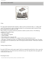
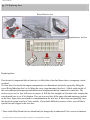
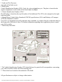
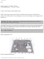
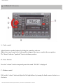
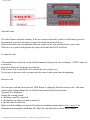
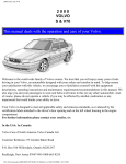
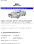
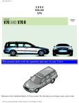
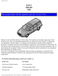
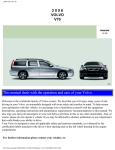
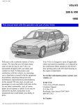
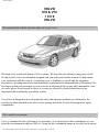
This manual deals with the operation and care of your Volvo.
Welcome to the world-wide family of Volvo owners. We trust that you will enjoy many years of safe
driving in your Volvo, an automobile designed with your safety and comfort in mind. To help ensure
your satisfaction with this vehicle, we encourage you to familiarize yourself with the equipment
descriptions, operating instructions and maintenance requirements/recommendations in this manual. We
also urge you and your passengers to wear seat belts at all times in this (or any other) automobile. And,
of course, please do not operate a vehicle if you may be affected by alcohol, medication or any
impairment that could hinder your ability to drive.
Your Volvo is designed to meet all applicable safety and emission standards, as evidenced by the
certification labels attached to the driver's door opening and on the left wheel housing in the engine
compartment.
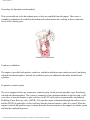
Volvo and the environment
Volvo is committed to the well being of our customers. As a natural part of this commitment, we care
about the environment in which we all live. Caring for the environment means an everyday involvement
file:///K|/ownersdocs/1999/1999_SV70/99sv70_000.htm (1 of 4)12/30/2006 3:36:45 PM
1999 S70 & V70
in reducing our environmental impact.
Volvo's environmental activities are based on a holistic view, which means we consider the overall
environmental impact of a product throughout its complete life cycle. In this context, design, production,
product use, and recycling are all important considerations.
In production, Volvo has partly or completely phased out several chemicals including freons, lead
chromates, naphtanates, asbestos, mercury and cadmium; and reduced the amount of chemicals used in
our plants 50% since 1991.
In use, Volvo was the first in the world to introduce into production a three-way catalytic converter with
a Lambda sond, now called oxygen sensor, in 1976. The current version of this highly efficient system
reduces emissions of harmful substances (CO, HC, NOx) from the exhaust pipe by approximately 95%
and the search to eliminate the remaining emissions continues. Volvo is the only automobile
manufacturer to offer CFC-free retrofit kits for the air conditioning system for all models back to the M/
Y 1975 240. Advanced electronic engine controls, refined purification systems and cleaner fuels are
bringing us closer to our goal.
After Volvo cars and parts have fulfilled their use, recycling is the next critical step in completing the
life cycle. The metal content is about 75% of the total weight of the car, which makes the car among the
most recycled industrial products. In order to have efficient and well controlled recycling, many Volvo
variants have printed dismantling manuals indication the weight and material of individual components.
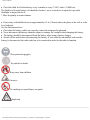
For Volvo, all homogeneous plastic parts weighing more than 1.7 oz. (50 grams)are marked with
international symbols that indicate how the component is to be sorted for recycling.
In addition to continuous environmental refinement of conventional gasoline-powered internal
combustion engines, Volvo is actively looking at advanced technology alternative-fuel vehicles.
When you drive a Volvo, you become our partner in the work to lessen the car's impact on the
environment. To reduce your vehicle's environmental impact, you can:
●
●
●
●
Maintain proper air pressure in your tires. Tests have shown decreased fuel economy with
improperly inflated tires Follow the recommended maintenance schedule
Drive at a constant speed
See an authorized Volvo retailer as soon as possible for inspection if the check engine
(malfunction indicator) lamp illuminates, or stays on after the vehicle has started
Properly dispose of any vehicle related waste such as used motor oil, used batteries, brake pads,
file:///K|/ownersdocs/1999/1999_SV70/99sv70_000.htm (2 of 4)12/30/2006 3:36:45 PM
1999 S70 & V70
●
etc.
When cleaning your car, use Volvo's own car care products, all of which have systematically
been adapted to the environment.
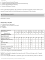
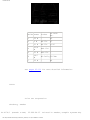
Contents
Table of Contents
Page No. Chapter and Subject
pg. 1
Chapter 1 - Occupant safety
pg. 16
Chapter 2 - Instruments and controls
pg. 41
Chapter 3 - Body and interior
pg. 65
Chapter 4 - Starting and driving
pg. 85
Chapter 5 - Wheels and tires
pg. 91
Chapter 6 - In case of emergency
pg. 109 Chapter 7 - Car care
pg. 115 Chapter 8 - Volvo Service
pg. 133 Chapter 9 - Specifications
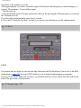
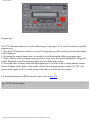
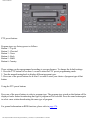
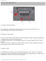
pg. 141 Chapter 10 - Audio systems
pg. 198 Index
Important
Before you operate your car for the first time, please familiarize yourself with the BREAK-IN
information on page 66. You should also be familiar with the information in the first three chapters of
this manual.
Information contained in the balance of the manual is extremely useful and should be studied after
operating the vehicle for the first time.
This manual is structured so that it can be used for reference. It should thus be kept in the car for ready
access.
Do not export your Volvo to another country before investigating the country's applicable safety and
exhaust emission requirements. In some cases it may be difficult or impossible to comply with these
requirements. Modifications to the emission control system(s) may render your Volvo not certifiable for
legal operation in the U.S., Canada or other countries.
All information, illustrations and specifications contained in this manual are based on the latest product
information available at the time of publication. Please note that some vehicles may be equipped
differently, depending of special legal requirements and that optional equipment described in this
file:///K|/ownersdocs/1999/1999_SV70/99sv70_000.htm (3 of 4)12/30/2006 3:36:45 PM
1999 S70 & V70
manual may not be available in all markets.
Volvo reserves the right to make model changes at any time, or to change specifications or design,
without notice and without incurring obligation.
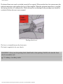
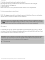
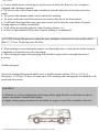
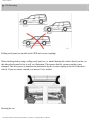
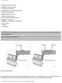
CAUTION: Certain models have reduced ground clearance due to the design of the front spoiler.
Please observe caution when e.g., driving onto garage hoists, through drifted snow or when other road
debris is encountered, or when parking near curbs.
©1998 Volvo Cars of North America Inc.
Contents | Top of Page
file:///K|/ownersdocs/1999/1999_SV70/99sv70_000.htm (4 of 4)12/30/2006 3:36:45 PM
1999 S70 & V70
Chapter 1 - Occupant safety
pg. 1 Occupant safety
Occupant safety
Despite our strongest recommendations, and your best intentions, not wearing a seat belt is like
believing "It'll never happen to me!". Volvo urges you and all adult occupants of your car to wear seat
belts and ensure that children are properly restrained, using an infant, car or booster seat determined by
age, weight and height.
Fact: In every state and province, some type of child-restraint legislation has been passed. Additionally,
most states and provinces have already made it mandatory for occupants of a car to use seat belts.
So, urging you to "buckle up" is not just our recommendation - legislation in your state or province may
mandate seat belt usage. The few seconds it takes to buckle up may one day allow you to say, "It's a
good thing I was wearing my seat belt".
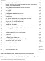
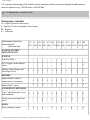
Chapter Contents
Page No. Subject
pg. 2
Seat belts
pg. 4
Volvo SRS
pg. 8
Side Impact Protection System - (SIPS) air
bag
pg. 9
Child safety
pg. 14
Occupant safety
pg. 14
Reporting Safety Defects
pg. 2 Seat belts
Seat belts
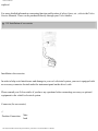
Always fasten the seat belts before you drive or ride.
file:///K|/ownersdocs/1999/1999_SV70/99sv70_001.htm (1 of 4)12/30/2006 3:36:45 PM
1999 S70 & V70
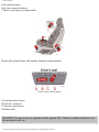
Two lights above the rear view mirror will be illuminated for 4-8 seconds after the starting (ignition) key
is turned to the driving position. A chime will sound at the same time if the driver has not fastened his
seat belt. The rear seats are provided with self-retracting inertia reel belts. The front seats are provided
with single roller belts with tensioners.
To buckle:
Pull the belt out far enough to insert the latch plate into the receptacle (buckle for rear seats) until a
distinct snapping sound is heard. The seat belt retractor is normally "unlocked" and you can move freely,
provided that the shoulder belt is not pulled out too far. The retractor will lock up as follows:
if the belt is pulled out rapidly
● during braking and acceleration
● if the vehicle is leaning excessively
● when driving in turns
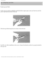
For the seat belt to provide maximum protection in the event of an accident, it must be worn correctly.
When wearing the seat belt remember:
● The belt should not be twisted or turned.
● The lap belt must be positioned low on the hips (not pressing against the abdomen).
● The shoulder section of the front seat belts adjusts automatically to the driver's height.
Make sure that the shoulder belt is rolled up into its retractor and that the shoulder and lap belts are taut.
Before exiting the car, check that the seat belt retracts fully after being unbuckled.
If necessary, guide the belt back into the retractor slot.
●
NOTE: Legislation in your state or province may mandate seat belt usage.
file:///K|/ownersdocs/1999/1999_SV70/99sv70_001.htm (2 of 4)12/30/2006 3:36:45 PM
1999 S70 & V70
WARNING! Any device used to induce slack into the shoulder belt portion of the three-point belt
system will have a detrimental effect on the amount of protection available to you in the event of a
collision. The seat back should not be tilted too far back. The shoulder belt must be taut in order to
function properly.
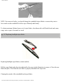
Spool-out
To make child seat installation easier, each seat belt buckle (except for the driver's belt) is equipped with
a locking mechanism to help keep the lap section of the seat belt taut. Please refer to page 12 for more
information on this function.
WARNING! Do not use child safety seats or child booster cushions/backrests in the front passenger's
seat. We also recommend that children who have outgrown these devices sit in the rear with the seat
belt properly fastened.
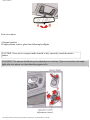
pg. 3 Seat belts, Center head restraint
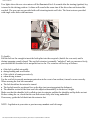
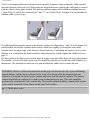
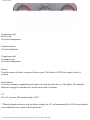
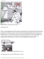
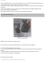
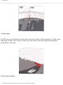
During pregnancy
Pregnant women should always wear seat belts. Remember that the belt should always be positioned in
such a way as to avoid any possible pressure on the abdomen. The lap portion of the belt should be
file:///K|/ownersdocs/1999/1999_SV70/99sv70_001.htm (3 of 4)12/30/2006 3:36:45 PM
1999 S70 & V70
located low, as shown in the above illustration.
WARNING! Never use a seat belt for more than one occupant. Never wear the shoulder portion of the
belt under the arm, behind the back or otherwise out of position. Such use could cause injury in event
of accident. As the seat belts lose much of theirstrength when exposed to violent stretching, they
should be replaced after any collision, even if they may appear to be undamaged. Never repair the belt
on your own; have this done by an authorized Volvo retailer only.
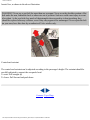
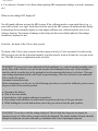
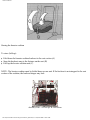
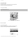
Center head restraint
The center head restraint can be adjusted according to the passenger's height. The restraint should be
carefully adjusted to support the occupant's head.
To raise: Pull straight up
To lower: Pull forward and push down
Contents | Top of Page
file:///K|/ownersdocs/1999/1999_SV70/99sv70_001.htm (4 of 4)12/30/2006 3:36:45 PM
1999 S70 & V70
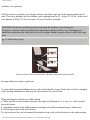
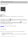
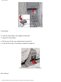
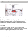
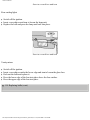
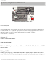
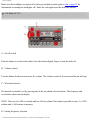
pg. 4 Volvo SRS
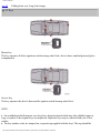
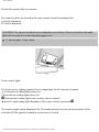
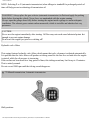
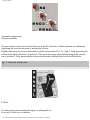
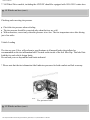
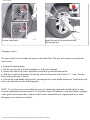
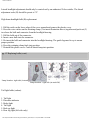
Passenger side SRS hatch
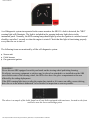
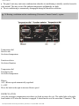
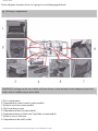
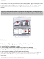
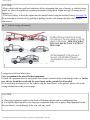
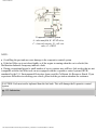
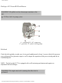
As an enhancement to the three-point seat belt system, your Volvo is equipped with a Supplemental
Restraint System (SRS). The Volvo SRS consists of an airbag (2) on both the driver's and passenger's
sides and seat belt tensioners in both front door pillars (4). The system is designed to supplement the
protection provided by the three-point seat belt system.
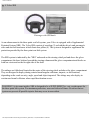
The SRS system is indicated by the "SRS" embossed on the steering wheel pad and above the glove
compartment, the knee bolsters beneath the steering column and the glove compartment and decals on
both sun visors and on the far right side of the dash.
The airbags are folded and located in the center of the steering wheel and above the glove compartment.
They are designed to deploy during certain frontal-angular collisions, impacts, or decelerations,
depending on the crash severity, angle, speed and object impacted. The airbags may also deploy in
certain non-frontal collisions where rapid deceleration occurs.
WARNING! As its name implies, SRS is designed to be a SUPPLEMENT to - not a replacement for the three-point belt system. For maximum protection, wear seat belts at all times. Be aware that no
system can prevent all possible injuries that may occur in an accident.
file:///K|/ownersdocs/1999/1999_SV70/99sv70_004.htm (1 of 8)12/30/2006 3:36:46 PM
1999 S70 & V70
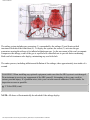
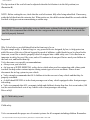
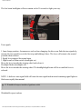
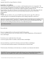
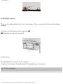
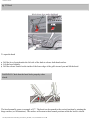
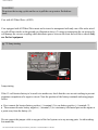
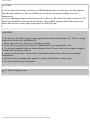
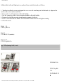
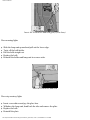
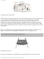
The airbag system includes gas generators (1) surrounded by the airbags (2) and front seat belt
tensioners for both of the front seats (4). To deploy the system, the sensor (3) activates the gas
generators causing the airbags to be inflated withnitrogen gas. As the movement of the seat's occupants
compresses the airbags, some of the gas is expelled at a controlled rate to provide better cushioning.
Both seat belt tensioners also deploy, minimizing any seat belt slack.
The entire process, including inflation and deflation of the airbags, takes approximately two-tenths of a
second.
WARNING! When installing any optional equipment, make sure that the SRS system is not damaged.
Do not attempt to service any component of the SRS yourself. Attempting to do so may result in
serious personal injury. If a problem arises, take your car tothe nearest authorized Volvo retailer for
inspection as soon as possible.
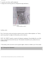
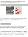
pg. 5 Volvo SRS (cont.)
NOTE: All doors will automatically be unlocked if the airbags deploy.
file:///K|/ownersdocs/1999/1999_SV70/99sv70_004.htm (2 of 8)12/30/2006 3:36:46 PM
1999 S70 & V70
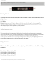
A self-diagnostic system incorporated in the sensor monitors the SRS. If a fault is detected, the "SRS"
warning light will illuminate. The light is included in the warning/indicator light cluster in the
instrument panel. Normally, the SRS warning lamp should light up when the ignition is switched on and
should go out after 5 seconds or when the engine is started. Check that this light is functioning properly
every time the car is start ed.
The following items are monitored by all the self-diagnostic system:
●
●
●
Sensor unit
Cable harness
Gas generator ignitors
WARNING!
Never drive an SRS equipped car with your hands on the steering wheel pad/airbag housing.
No objects, accessory equipment or stickers may be placed on, attached to or installed near the SRS
cover in the center of the steering wheel, the SRS cover above the glove compartment or the area
affected by the airbag deployment.
If the SRS warning light stays on after the engine has started or if it comes on while you are driving,
drive the car to the nearest authorized Volvo retailer for inspection as soon as possible.
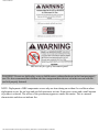
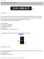
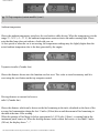
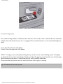
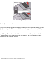
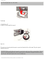
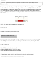
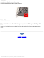
The above is a sample of the label found on all seat belts equipped with tensioners, located on the front
seat belts near the lower anchorage point.
file:///K|/ownersdocs/1999/1999_SV70/99sv70_004.htm (3 of 8)12/30/2006 3:36:46 PM
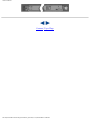
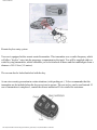
1999 S70 & V70
The above is a sample of the decal which can be found on the driver's door pillar.
There is no maintenance to perform on the SRS yourself. The only periodic maintenance recommended
on the SRS is that the air bag modules and front seat belts (including tensioners) should be replaced
approximately every ten years and that the other components in the system (wiring, connectors, etc.)
should also be inspected at this time. The SRS decal on your car shows the month and year servicing is
due. This service must be performed by an authorized Volvo retailer.
Should you have any questions about the SRS system, please contact your authorized Volvo retailer or
Volvo Customer Support.
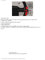
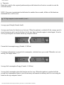
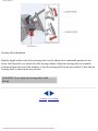
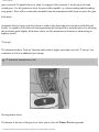
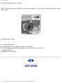
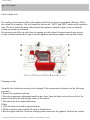
pg. 6 Volvo SRS (cont.)
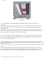
Passenger side air bag
file:///K|/ownersdocs/1999/1999_SV70/99sv70_004.htm (4 of 8)12/30/2006 3:36:46 PM
1999 S70 & V70
SRS texts as far right of instrument panel
WARNING! Do not use child safety seats or child boosters cushions/backrests in the front passenger's
seat. We also recommend that children who have outgrown these devices sit in the rear seat with the
seat belt properly fastened.
NOTE: Deployment of SRS components occurs only one time during an accident. In a collision where
deployment occurs, the air bags and seat belt tensioners activate. Some noise occurs and a small amount
of powder is released. The release of the powdermay appear as smoke-like matter. This is a normal
characteristic and does not indicate fire.
file:///K|/ownersdocs/1999/1999_SV70/99sv70_004.htm (5 of 8)12/30/2006 3:36:46 PM
1999 S70 & V70
WARNING!
Children must never be allowed in the front passenger seat. Volvo recommends that ALL occupants
(adults and children) shorter than four feet seven inches (140 cm) be seated in the back seat of the
vehicle with a front passenger side airbag. See page 12 for guidelines.
● Occupants in the front passenger's seat must never sit on the edge of the seat, sit leaning toward the
instrument panel or otherwise sit out of position. The occupant's back must be as upright as comfort
allows and be against the seat back with the seat belt properly fastened.
● Feet must be on the floor, e.g. not on the dash, seat or out of the window.
● No objects or accessory equipment, e.g. dash covers, may be placed on, attached to or installed near
the SRS hatch (the area above the glove compartment) or the area affected by airbag deployment (see
illustration).
● There should be no loose articles, e.g. coffee cups, on the floor, seat or dash area.
● Never try to open the SRS cover on the steering wheel or the passenger side SRS hatch. This should
only be done by an authorized Volvo service technician.
● Failure to follow these instructions can result in injury to the vehicle occupants in an accident.
●
pg. 7 Volvo SRS (cont.)
NOTE: The information on this page does not pertain to the Side Impact protection System airbags.
When are the airbags deployed?
The SRS system is designed to deploy during certain frontal or front-angular collisions, impacts, or
decelerations, depending in the crash severity, angle, speed, and object impacted. The SRS sensor is
designed to react to both the impact of thecollision and the inertial forces generated by it and to
determine if the intensity of the collision is sufficient for the airbags to be deployed.
WARNING! The SRS is designed to help prevent serious injury. Deployment occurs very quickly and
with considerable force. During normal deployment and depending on variables such as seating
position, one may experience abrasions, bruises, swellings, orother injuries as a result of airbag(s)
deployment.
If the airbags have been deployed, we recommend the following:
●
●
Have the car towed to an authorized Volvo retailer. Never drive with the airbags deployed.
Have an authorized Volvo retailer replace the SRS system components.
file:///K|/ownersdocs/1999/1999_SV70/99sv70_004.htm (6 of 8)12/30/2006 3:36:46 PM
1999 S70 & V70
Use only new, Genuine Volvo Parts when replacing SRS components (airbags, seat belts, tensioners,
etc.)
●
When are the airbags NOT deployed?
Not all frontal collisions activate the SRS system. If the collision involves a non-rigid object (e.g., a
snow drift or bush), or a rigid, fixed object at a low speed, the SRS system will not necessarily deploy.
Front airbags do not normally deploy in a side impact collision, in a collision from the rear or in a
rollover situation. The amount of damage to the bodywork does not reliably indicate if the airbags
should have deployed or not.
Seat belts - the heart of the Volvo safety system
The heart of the Volvo safety system is the three-point seat belt (a Volvo invention)! In order for the
SRS system to provide the protection intended, seat belts must be worn at all times by everyone in the
car. The SRS system is a supplement to the seat belts.
WARNING! If your car has been subjected to flood conditions (e.g. soaked carpeting/standing water
on the floor of the vehicle) or if your car has become flood-damaged in any way, do not attempt to
start the vehicle or put the key in the ignition before disconnecting the battery (see below). This may
cause airbag deployment which could result in personal injury. Have the car towed to an authorized
Volvo retailer for repairs.
Automatic transmission only:
Before attempting to tow the car, use the following procedure to override the shiftlock system to move
the gear selector to the neutral position.
●
●
●
●
●
Disconnect the battery
Wait at least one minute
Insert the key in the ignition and turn it to position 1
Press firmly on the shiftlock override button (located near the base of the gear selector).
While holding the override button down, move the gear selector from the park position.
WARNING! Never drive with the airbags deployed. The fact that they hang out can impair the
steering of your car. Other safety systems can also be damaged. The smoke and dust formed when the
airbags are deployed can cause skin and eye irritation in the event of prolonged exposure.
file:///K|/ownersdocs/1999/1999_SV70/99sv70_004.htm (7 of 8)12/30/2006 3:36:46 PM
1999 S70 & V70
Contents | Top of Page
file:///K|/ownersdocs/1999/1999_SV70/99sv70_004.htm (8 of 8)12/30/2006 3:36:46 PM
1999 S70 & V70
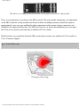
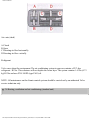
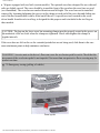
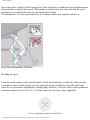
pg. 8 Volvo Side Impact Protection System (SIPS) airbag
SIPS airbag decal *
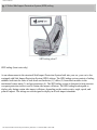
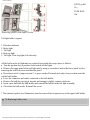
SIPS airbag (front seats only)
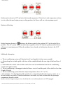
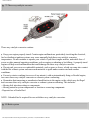
As an enhancement to the structural Side Impact Protection System built into your car, your car is also
equipped with Side Impact Protection System (SIPS) airbags. The SIPS airbag system consists of airbag
modules built into the sides of both front seat backrests (1), cables (2) from these modules to the
mechanical sensor units (3) and gas generators (4). The SIPS airbag system is designed to help increase
occupant protection in the event of certain side impact collisions. The SIPS airbags aredesigned to
deploy only during certain side-impact collisions, depending on the crash severity, angle, speed, and
point of impact. The airbags are not designed to deploy in all side impact situations.
file:///K|/ownersdocs/1999/1999_SV70/99sv70_008.htm (1 of 10)12/30/2006 3:36:47 PM
1999 S70 & V70
WARNING!
The SIPS airbag system is a supplement to the Side Impact Protection System and the three-point
seat belt system. It is not designed to deploy during collisions from the front or rear of the car or in
rollover situations.
● The use of seat covers on the front seats may impede SIPS airbag deployment.
● No objects, accessory equipment or stickers may be placed on, attached to or installed near the SIPS
airbag system or in the area affected by SIPS airbag deployment (see illustration to the right above).
● Never try to open or repair any components of the SIPS airbag system. This should only be done by
an authorized Volvo service technician.
● For best protection from the SIPS airbag system, both front seat occupants should sit in an upright
position with the seat belt properly fastened.
●
NOTE: SIPS airbag deployment (one airbag) occurs only on the side of the vehicle affected by the
impact.
1 - Airbag, 2 - cable, 3 - sensor unit, 4 - gas generator
WARNING!
Never drive with the airbags deployed. The fact that they hang out can impair the steering of your
car. Other safety systems can also be damaged. The smoke and dust formed when the airbags are
deployed can cause skin and eye irritation in the event of prolonged exposure.
● If your car has been subjected to flood conditions (e.g. soaked carpeting/standing water on the floor
of the vehicle) or if your car has become flood-damaged in any way, do not attempt to start the vehicle
or put the key in the ignition beforedisconnecting the battery. This may cause airbag deployment
which could result in personal injury. Have the car towed to an authorized Volvo retailer for repairs.
●
pg. 9 Child safety
file:///K|/ownersdocs/1999/1999_SV70/99sv70_008.htm (2 of 10)12/30/2006 3:36:47 PM
1999 S70 & V70
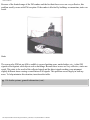
Sedan
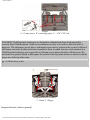
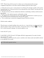
Child Restraint Anchorages
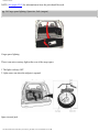
Volvo cars are fitted with Child Restraint Top Tether Anchorages in the rear seat.
Sedans: There are three pre-drilled anchorage points under the rear window shelf which are not visible
from the passenger compartment.
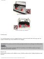
Wagons: The anchorage points are on the rear seat backrest and are hidden by plastic covers. The
backrest must be folded down to access the center anchorage point.
In cars designed for Canada, one top tether anchorage set will be in the glove box.
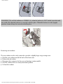
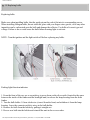
Installing the top tether
Sedans: The pre-drilled holes for the child restraint anchorages are underneath the rear window shelf and
can be accessed from the trunk or by lowering the rear seat backrests.
Wagons: Remove the plastic cover from the anchorage point you intend to use.
On either model, refer to the child seat manufacturer's instructions for securing the seat.
file:///K|/ownersdocs/1999/1999_SV70/99sv70_008.htm (3 of 10)12/30/2006 3:36:47 PM
1999 S70 & V70
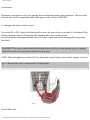
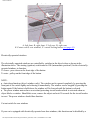
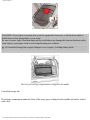
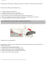
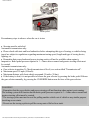
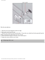
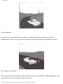
Wagon
A - 10 mm spacer, B - anchorage plate, C - 5/16" UNC bolt
WARNING! Child Restraint Anchorages are designed to withstand only those loads imposed by
correctly fitted Child Restraints. Under no circumstances are they to be used for adult seat belts or
harnesses. The anchorages are not able to withstand excessiveforces on them in the event of collision if
full harness seat belts or adult seat belts are installed to them. An adult who uses a belt anchored in a
Child Restraint Anchorage runs a great risk of suffering severe injuries should a collision occur. Do
not install rear speakers which would require the removal of the top tether anchors or interfere with the
proper use of the top tether strap.
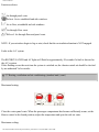
pg. 10 Child safety (cont.)
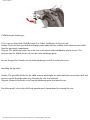
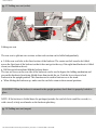
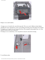
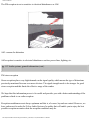
Integrated booster cushion:
1 - Sedan 2 - Wagon
Integrated booster cushion (optional)
file:///K|/ownersdocs/1999/1999_SV70/99sv70_008.htm (4 of 10)12/30/2006 3:36:47 PM
1999 S70 & V70
Volvo's own integrated booster cushion has been specially designed to help safeguard a child seated in
the center position of the rear seat. When using the integrated booster cushion, the child must be secured
with the vehicle's three-point seatbelt. The booster cushion is approved for children weighing between
15 and 40 kg (33 and 88 lbs) and between 97 and 137 cm (38 and 54 in ) in height. It is not intended for
children under 3 years of age.
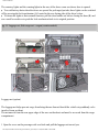
The child should be properly seated on the booster cushion (see illustrations 1 and 2 in left column). For
small children, the booster cushion backrest can be tilted back slightly by raising the center head
restraint above the upper edge of the booster cushion backrest (3) and tilting the backrest (4). For taller
children, it is essential that the head restraint be adjusted properly to help support the child's head (see
page 3).
The hip section of the three-point seat belt must fit snugly across the child's hips, not across the stomach.
The shoulder section of the three-point seat belt should be positioned across the chest and shoulder (see
illustration). The shoulder belt must never be placed behind the child's back or under the arm.
WARNING! Failure to follow the instructions on this page will increase the risk of your child being
injured during a sudden stop or collision. In the event of a collision while the integrated booster
cushion was occupied, the entire booster cushion and center seat belt must be replaced. The booster
cushion should also be replaced if it is badly worn or damaged in any way. This work should be
performed by an authorized Volvo retailer only. The booster cushion should be cleaned while in place
in the vehicle if possible. If not, please consult your Volvo retailer.
pg. 11 Child safety (cont.)
file:///K|/ownersdocs/1999/1999_SV70/99sv70_008.htm (5 of 10)12/30/2006 3:36:47 PM
1999 S70 & V70
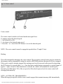
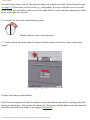
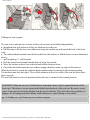
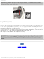
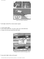
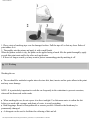
Storing the booster cushion
To store (fold up):
●
●
●
Fold down the booster cushion backrest to the seat section (A)
Snap the backrest snap to the fastener on the seat (B)
Fold up the booster cushion unit (C)
NOTE: The booster cushion must be folded down as one unit. If the backrest is not strapped to the seat
section of the cushion, the backrest hinges may lock.
Auxiliary seat - A-Fold up, B-Fold down
file:///K|/ownersdocs/1999/1999_SV70/99sv70_008.htm (6 of 10)12/30/2006 3:36:47 PM
1999 S70 & V70
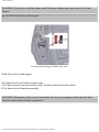
Auxiliary seat (optional)
If all the seats are occupied, a rear-facing auxiliary seat in the cargo area of the wagon models can be
used. This seat is designed for two children, each weighing between 23 - 40 kg (50 - 88 lbs.) with a total
seat capacity of 80 kg (176 lbs.) and up to 150 cm (59 inches) in height.
WARNING! Both rear seat backrests must be up when the auxiliary seat is being used.
Do not use a booster cushion or child seat in conjunction with the auxiliary seat. The luggage net
should be retracted and the child safety lock in the tailgate should be open to allow access to the cargo
area.
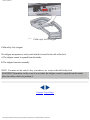
pg. 12 Child safety (cont.)
A-Lap section of belt locked in place, B-Lap section functions normally
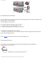
Keeping child seats in place (spool-out)
To make child restraint installation easier, each seat belt buckle (except for the driver's belt) is equipped
with a locking mechanism to help keep the lap section of the seat belt taut.
When attaching the seat belt to a child restraint:
● Make sure the red lock button is moved to the right (see illustration A). A coin, etc.. can be used to
move the button.
● Attach the seat belt to the child restraint according to the child seat manufacturer's instructions.
● Pull the lap section of the seat belt taut.
The lap section of the seat belt cannot be loosened as long as the red lock button is in the right position.
file:///K|/ownersdocs/1999/1999_SV70/99sv70_008.htm (7 of 10)12/30/2006 3:36:47 PM
1999 S70 & V70
The lap section of the seat belt can be adjusted when the lock button is in the left position (see
illustration B).
NOTE: Before exiting the car, check that the seat belt retracts fully after being unbuckled. If necessary,
guide the belt back into the retractor slot. When not in use, the child restraint should be secured with the
seat belt to help prevent movementduring a sudden stop.
WARNING! Do not use child safety seats or child booster cushions/backrests in the front passenger's
seat. We also recommend that children who have outgrown these devices sit in the rear seat with the
seat belt properly fastened.
Important!
Why Volvo believes no child should sit in the front seat of a car.
It's quite simple really. A front air bag is a very powerful device designed, by law, to help protect an
adult. Because of the size of the air bag and its speed of inflation, a child should never be placed in the
front seat, even if he or shed is properly belted or strapped into a child safety seat. Volvo has been an
innovator in safety for over fifty years, and we'll continue to do our part. But we need your children in
the back seat, and buckle them up.
Volvo has some very specific recommendations:
● Always wear your seat belt.
● Air bags are a SUPPLEMENTAL safety device which when used in conjunction with a three-point
seat belt can help reduce serious injuries during certain types of severe accidents. Please do not
disconnect the air bag system in your vehicle.
● Volvo strongly recommends that ALL children sit in the rear seat of any vehicle and that they be
properly restrained.
● A child should NEVER sit in the front passenger seat of any vehicle equipped with a front passenger
side airbag.
● Volvo recommends that ALL occupants (adults and children) shorter than four feet seven inches (140
cm) be seated in the back seat of any vehicle with a front passenger side airbag.
Drive safely!
pg. 13 Child safety (cont.)
Child safety
Volvo recommends the proper use of restraint systems for all occupants including children. Remember
file:///K|/ownersdocs/1999/1999_SV70/99sv70_008.htm (8 of 10)12/30/2006 3:36:47 PM
1999 S70 & V70
that, regardless of age and size, a child should always be properly restrained in a car.
Restraint systems for children are designed to be secured in the vehicle by lap belts or the lap portion of
a lap-shoulder belt. Such child restraint systems can help protect children in cars in the event of an
accident only if they are used properly. However, children could be endangered in a crash if the child
restraints are not properly secured in the vehicle. Failure to follow the installation instructions for your
child restraint can result in your child striking the vehicle's interior in a sudden stop.
Holding a child in your arms is NOT a suitable substitute for a child restraint system. In an accident, a
child held in a person's arms can be crushed between the vehicle's interior and an unrestrained person.
The child could also be injured bystriking the interior, or by being ejected from the vehicle during a
sudden maneuver or impact. The same can also happen if the infant or child rides unrestrained on the
seat. Other occupants should also be properly restrained to help reduce the chanceof injuries or
increasing the injury of a child.
All states and provinces have legislation governing how and where children should be carried in a car.
Find out the regulations existing in your state or province. Recent accident statistics have shown that
children are safer in rear seating positions than front seating positions when properly restrained. A child
restraint system can help protect a child in a vehicle. Here's what to look for when selecting a child
restraint system:
● It should have a label certifying that it meets applicable Federal Motor Vehicle Safety Standards
(FMVSS 213) - or in Canada, CMVSS 213.
● Make sure the child restraint system is approved for the child's height, weight and development - the
label required by the standard or regulation, or instructions for infant restraints, typically provide this
information.
● In using any child restraint system, we urge you to look carefully over the instructions that are
provided with the restraint. Be sure you understand them and can use the device properly and safely in
this vehicle. A misused child restraint system can result in increased injuries for both the infant or child
and other occupants in the vehicle.
● If your child restraint requires a top tether strap, consult your authorized Volvo retailer for top tether
anchorage and installation information.
When a child has outgrown the child safety seat, you should use the rear seat with the standard seat belt
fastened. The best way to help protect the child here is to place the child on a cushion so that the seat
belt is properly located on the hips (see page 10).
A specially designed and tested booster (not available in Canada) cushion for children between 22.7 - 36
kg (50 - 80 lbs) and 117 - 137 cm (46 - 54") can be obtained from your Volvo retailer.
If necessary, an auxiliary seat for children is available for use in the luggage compartment of station
wagon models. This seat is designed for two children, each weighing between 23 - 40 kg (50 - 88 lbs.)
file:///K|/ownersdocs/1999/1999_SV70/99sv70_008.htm (9 of 10)12/30/2006 3:36:47 PM
1999 S70 & V70
and up to 150 cm (59 inches) in height.
WARNING!
When using the auxiliary seat for children, both sections of the rear seat backrest must be secured in
the upright position
● Do not use a booster cushion or child seat in conjunction with the auxiliary seat.
●
Contents | Top of Page
file:///K|/ownersdocs/1999/1999_SV70/99sv70_008.htm (10 of 10)12/30/2006 3:36:47 PM
1999 S70 & V70
pg. 14 Occupant safety
Seat belt maintenance
Check periodically that the anchor bolts are secure and that the belts are in good condition. Use water
and a mild detergent for cleaning. Check seat belt mechanism function as follows: Attach the seat belt
and pull rapidly on the strap.
Volvo Concern for Safety
Safety is the cornerstone for Volvo. Our concern dates back to 1927 when the first Volvo rolled off the
production line. Three-point seat belts (a Volvo invention), safety cages, and energy-absorbing impact
zones were designed into Volvo cars long before it was fashionable or required by government
regulation. We will not compromise our commitment to safety. We continue to seek out new safety
features and to refine those already in our cars. You can help. We would appreciate hearing your
suggestions about improving automobile safety. We also want to know if you ever have a safety concern
with your car.
Occupant safety
How safely you drive doesn't depend on how old you are but rather on:
how well you see
● your ability to concentrate
● how quickly you make decisions under stress to avoid an accident.
The tips listed below are suggestions to help you cope with the ever changing traffic environment.
● Never drink and driver.
● If you are taking any medication, consult your physician about its potential effects on your driving
abilities.
● Take a driver-retaining course
● Have your eyes checked regularly
● Keep your windshield and headlamps clean.
● Replace wiper blades when they start to leave streaks.
● Take into account the traffic, road, and water conditions, particularly with regard to stopping distance.
●
file:///K|/ownersdocs/1999/1999_SV70/99sv70_014.htm (1 of 2)12/30/2006 3:36:47 PM
1999 S70 & V70
Reporting Safety Defects in the U.S.
If you believe that your vehicle has a defect which could cause a crash or could cause injury or death,
you should immediately inform the National Highway Traffic Safety Administration (NHTSA) in
addition to notifying Volvo Cars of North America. If NHTSA receives similar complaints, it may open
an investigation, and if it finds that a safety defect exists in a group of vehicles, it may order a recall and
remedy campaign. However, NHTSA cannot become involved in individual problems between you,your
retailer, or Volvo Cars of North America. To contact NHTSA, you may either call the Auto Safety
Hotline toll-free at 1-800-424-9393 (or 202-366-0123 in Washington, D.C. area) or write to: NHSTA, U.
S. Department of Transportation, Washington D.C. 20590. You can also obtain other information about
motor vehicle safety from the Hotline.
Contents | Top of Page
file:///K|/ownersdocs/1999/1999_SV70/99sv70_014.htm (2 of 2)12/30/2006 3:36:47 PM
1999 S70 & V70
Chapter 2 - Instruments and controls
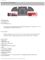
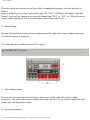
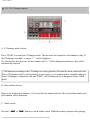
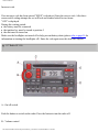
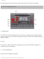
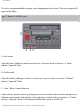
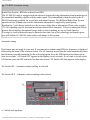
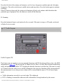
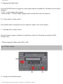
pg. 16 Instruments, switches and controls
pg. 17 Instruments, switches and controls (cont.)
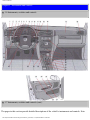
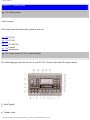
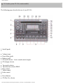
The pages in this section provide detailed descriptions of the vehicle's instruments and controls. Note
file:///K|/ownersdocs/1999/1999_SV70/99sv70_016.htm (1 of 4)12/30/2006 3:36:47 PM
1999 S70 & V70
that vehicles may be equipped differently, depending on special legal requirements.
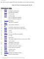
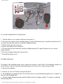
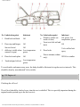
Chart for Picture of Instruments and Controls
Number Page No. Subject
pg. 35
Air vents
1
2
pg. 22
Headlights, parking lights
3
pg. 24
Instrument illumination
4
pg. 24
Rear fog light
5
pg. 24
Front fog lights
6
7
Space for additional equipment
Space for additional equipment
8
pg. 16-17 Instruments
9
pg. 25
TRACS/STC (optional)
10
pg. 2830
Trip computer (optional)
11
pg. 52
Electrically operated sun roof (optional)
12
pg. 25
Rear window demister/heated door mirrors
13
pg. 35
Air mix
14
pg. 35
Air vents
15
pg. 4-6
Passenger side SRS (air bag) hatch
16
pg. 35
Air vents
17
pg. 53
Hood release
18
pg. 22
Turn signals, high/low beams/exterior courtesy lights
pg. 31
Cruise control
19
pg. 34
Adjustable steering wheel
20
pg. 23
Windshield wiper/washer
:
pg. 26
Tailgate wiper/washer (wagons)
21
pg. 32
Heated front seats (optional)
22
pg. 33
Auxiliary socket
23
pg. 141
Audio system
24
pg. 35-39 Heating and ventilation controls
25
pg. 25
Hazard warning flashers
file:///K|/ownersdocs/1999/1999_SV70/99sv70_016.htm (2 of 4)12/30/2006 3:36:47 PM
1999 S70 & V70
26
pg. 33
27
Ash tray
Coin holder
28
pg. 108
29
pg. 70-71 Gear selector shift positions
30
pg. 72
Winter mode selectors
31
pg. 32
Parking brake
32
pg. 4-6
Horn/SRS
33
pg. 47
Trunk/tailgate open control
34
pg. 40
Power window controls
35
pg. 50
Power mirror controls
36
pg. 67
Fuel tank open control
37
pg. 43
Central locking button
Shiftlock release button (automatic transmission only)
Some of the items above are available on certain models only.
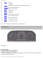
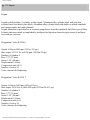
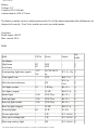
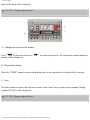
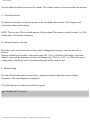
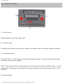
pg. 18 Instruments
1 Fuel gauge
Fuel tank capacity:
18 US gals. (68 liters) Front Wheel Drive
17.4 US gals. (66 liters) All Wheel Drive
. When the warning light comes on there is approximately 1.8 US gals. (8 liters) of fuel remaining. See
"Refueling" for further information.
file:///K|/ownersdocs/1999/1999_SV70/99sv70_016.htm (3 of 4)12/30/2006 3:36:47 PM
1999 S70 & V70
2 Temperature gauge
Do not drive the car with the pointer in the red range. The pointer should be
approximately midway on the gauge face when driving. If the pointer approaches the red
range repeatedly, check coolant level. See page 130.
3 Speedometer
4 Clock, ambient temperature sensor, trip computer (certain models)
5 Trip odometer
Used for measuring shorter distances. The last digit indicates 1/10 mile/kilometer.
6 Odometer
7 Trip odometer reset button
8 Tachometer
Reads thousands of engine rpm.
Contents | Top of Page
file:///K|/ownersdocs/1999/1999_SV70/99sv70_016.htm (4 of 4)12/30/2006 3:36:47 PM
1999 S70 & V70
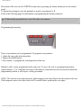
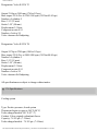
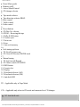
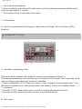
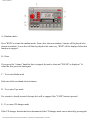
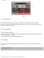
pg. 19 Indicator and warning lights
1 Turn signal, left
2 Turn signal , right
3 Cruse control
4 Low washer fluid level
If the lamp glows continuously when the engine is running, there is only about 1/2 - 1 US
qt. remaining in the washer fluid reservoir.
5 Low fuel level
When the lamp glows, only about 1.8 US gals. (8 liters) of fuel remain. If the ignition is
switched on while refueling, the gauge may read inaccurately for up to 45 minutes.
6 Rear fog light
7 High beams
8 Trunk/tailgate open
9 Bulb failure warning sensor
10 (Not in use)
11 Electronic Throttle System(ETS)
12 SRS
13 Generator not charging
14 Low engine oil pressure
15 Brake warning light
16 Parking brake applied
17 ABS-system
18 Transmission mode "W", or gear positions 3 or L engaged (automatic transmissions)
19 Low coolant level
file:///K|/ownersdocs/1999/1999_SV70/99sv70_019.htm (1 of 6)12/30/2006 3:36:48 PM
1999 S70 & V70
20 Traction Control (TRACS)/Stability and Traction Control (STC) Systems (option)
21 Malfunction indicator lamp
(See page 20 for more information)
22 Service reminder indicator
pg. 20 Warning lights
The warning lights described on pages 20 and 21 should never stay on when driving
When the ignition key is turned on, and before the engine starts, all of the warning lights should be on to
test the function of the bulbs. Should a light not go off after the engine has started, the system indicated
should be inspected. However, the parking brake reminder light will not go off until the parking brake is
fully released.
Supplemental Restraint System (SRS)
If the light comes on (or stays on after the vehicle has started), the SRS diagnostic system has detected a
fault. Drive to an authorized Volvo retailer for an inspection of the system. See the SRS section for more
information.
Malfunction indicator lamp
If the lamp comes on (or stays on after the vehicle has started), the engine diagnostic system has
detected a possible fault in the emission control system. Although driveability may not be affected, see
an authorized Volvo retailer as soon as possible for inspection.
NOTE: If the fuel filler cap is not closed tightly or if the engine is running when the car is refueled, the
Malfunction Indicator Lamp may indicate a fault. Use only Volvo original or approved fuel filler caps.
Oil pressure warning light
file:///K|/ownersdocs/1999/1999_SV70/99sv70_019.htm (2 of 6)12/30/2006 3:36:48 PM
1999 S70 & V70
If the light comes on while driving, stop the car and then stop the engine immediately and check the
engine oil level. See page 124. If the light stays on after restart, have the car towed to the nearest
authorized Volvo retailer. After hard driving, the light may come on occasionally when the engine is
idling. This is normal, provided it goes off when the engine speed is increased.
Parking brake reminder light
This light will be on when the parking brake (hand brake) is applied. The parking brake lever is situated
between the front seats. Canadian models are equipped with this warning light:
Brake fluid warning light
If the light comes on while driving or braking, stop immediately, open the hood and check the brake
fluid level in the reservoir. See page 131 for reservoir position.
Canadian models are equipped with this warning light:
WARNING! If the fluid level is below the MIN mark in either section of the reservoir: DO NOT
DRIVE. Tow the car to a Volvo retailer and have the brake system checked and any leakage repaired.
Fault in ETC (Electronic Throttle Control system)
If this lamp comes on, there is a fault in the engine control system and driveability will be affected.
Switch the ignition off and then on again. If the light remains on, the system should be inspected by an
authorized Volvo retailer.
pg. 21 Warning lights (cont.)
file:///K|/ownersdocs/1999/1999_SV70/99sv70_019.htm (3 of 6)12/30/2006 3:36:48 PM
1999 S70 & V70
TRACS disengaged (option)
If the TRACS (TRAction Control System) is manually disengaged with the switch on the dashboard (see
page 25), the warning light will come on. This will also come on to indicate a TRACS malfunction, and
when the brakes overheat, although it goes out again at the normal temperature level. If the lamp
remains on, the system should be checked by an authorized Volvo retailer. This lamp should not be
confused with the ON/OFF indicator lamp above the switch.
STC disengaged (option)
The indicator light ( ) in the instrument panel will be ON when you have switched the Stability and
Traction Control system (STC) OFF using the button of the dashboard (see page 25). The light will also
come on if there is a fault in the STC system or to indicate that the brakes have overheated. The light
will go out when the brake temperature returns to normal. Consult your Volvo retailer.
symbol will flash when STC is actively regulating power to the drive wheels. Normal power
The
may be reduced at this time. This is normal as power is momentarily reduced to help keep the drive
wheels from losing traction and spinning.
Coolant level sensor
If the light comes on while driving, the coolant level is low. The coolant level in the expansion tank
should be checked immediately and topped up if necessary. The cooling system should be inspected by
an authorized Volvo retailer.
Mode "W" engaged
The lamp will light up when the Winter/Wet starting mode is engaged or if gears "3" or "L" are selected.
If the warning lamp begins to flash , this means that there is a fault in the automatic gearbox. Contact
your Volvo retailer.
file:///K|/ownersdocs/1999/1999_SV70/99sv70_019.htm (4 of 6)12/30/2006 3:36:48 PM
1999 S70 & V70
Generator warning light
If the light comes on while the engine is running, have the charging system checked.
Service reminder indicator
This light will come on at 7,500 mile (12,000 km) intervals*, after 750 hours of driving or after 12
months, whichever occurs first. It is a reminder to the driver that the service interval has been exceeded.
The light will stay on for2 minutes after the start until reset by the servicing retailer.
* Turbo-charged model intervals: 5,000 miles (8,000 km), 500 hours of driving or after 12 months,
whichever occurs first.
Bulb failure warning light
The light will come on if any of the following bulbs are defective:
one of the low beam headlights
● one of the tail lights
● one of the brake lights when the brake pedal is depressed.
Check the fuse and bulb. See sections "Replacing bulbs" and "fuses".
Should the warning light come on after a defective outside bulb has been replaced, the corresponding
bulb on the other side of the car should also be replaced.
●
Anti-lock Brake System (ABS)
If the warning lamp lights up there is a malfunction of the ABS system (the standard braking system will
however function). The vehicle should be driven to a Volvo retailer for inspection.
See page 80 for additional information.
Canadian models are equipped with this warning light:
file:///K|/ownersdocs/1999/1999_SV70/99sv70_019.htm (5 of 6)12/30/2006 3:36:48 PM
1999 S70 & V70
Contents | Top of Page
file:///K|/ownersdocs/1999/1999_SV70/99sv70_019.htm (6 of 6)12/30/2006 3:36:48 PM
1999 S70 & V70
pg. 22 Headlights, Parking lights, Turn signals
Headlights and parking lights
O All lights off *
Parking lights on **
Headlights and parking lights are on if starting (ignition) switch is in positions I or II.
If the headlight switch is in position
With the headlight switch in position
running light screw (A) in position .
all lights will go out when starting switch is switched off.
the parking lights will stay on (headlights off) with the daytime
.
The high beams can only be switched on if the headlight switch is in position
Switch from high to low beams and vice versa by moving the turn signal switch lever on the left side of
the steering column towards the steering wheel.
* See page 26 for information on the Daytime running lights.
Exterior courtest lights
When you leave your car at night, you can make use of the exterior courtesy lighting function:
●
●
Remove the key from the ignition switch.
Pull the direction indicator lever towards the steering wheel (as when using the headlight flasher
function).
file:///K|/ownersdocs/1999/1999_SV70/99sv70_022.htm (1 of 8)12/30/2006 3:36:49 PM
1999 S70 & V70
The low beam headlights will now remain on for 30 seconds to light your way.
Turn signals
1 Lane change position : In maneuvers such as lane changing, the driver can flash the turn signals by
moving the turn signal lever to the first stop and holding it there. The lever will return to the neutral
position when released.
2 Signal lever engaged for normal turns
3 High beam/low beam switch (headlights on)
Move the lever towards the steering wheel and release it.
Headlight flasher (headlights off)
Move the lever towards the steering wheel. The headlight high beam will be on until the lever is
released.
NOTE: A defective turn signal bulb will cause the turn signal indicator and remaining signal lights to
flash more rapidly than normal.
pg. 23 Windshield wipers/washers, Ignition switch
Windshield wipers/washers
file:///K|/ownersdocs/1999/1999_SV70/99sv70_022.htm (2 of 8)12/30/2006 3:36:49 PM
1999 S70 & V70
1 Intermittent wiper
With switch in this position, the wipers will sweep approximately every seventh second.
2 "Single sweep" position.
The switch returns automatically when released
3 Wipers, normal speed.
4 Wipers, high speed
5 Windshield wiper/washer, headlight wiper/washer (certain models)
The wiper will make 2-3 complete sweeps across the windshield and headlights after the lever is
released.
O Locked position:
Remove the key to lock the steering wheel*
file:///K|/ownersdocs/1999/1999_SV70/99sv70_022.htm (3 of 8)12/30/2006 3:36:49 PM
1999 S70 & V70
WARNING: Never turn the key to position O while driving or when the car is
being towed.
I Intermediate position:
Certain accessories, radio, etc. on, daytime running lights off.
II Drive position:
Key position when engine is running.
III Starting position:
Release the key when the engine starts. The key returns automatically to the Drive
position.
* On cars equipped with an automatic transmission the gear selector must also be in
the (P)ark position.
Starting (ignition) switch/steering wheel lock
The steering wheel lock might be under tension when the car is parked. Turn the steering wheel slightly
to free the ignition key.
In order to reduce car theft, make sure the steering wheel lock is engaged before leaving the car.
A chime will sound if the starting key is left in the ignition lock and the front door on the driver's side is
opened.
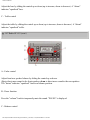
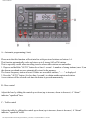
pg. 24 Instrument illumination, Fog lights
file:///K|/ownersdocs/1999/1999_SV70/99sv70_022.htm (4 of 8)12/30/2006 3:36:49 PM
1999 S70 & V70
1 - Instrument illumination
To increase the brightness: move the thumbwheel up.
To decrease the brightness: move the thumbwheel down.
2 - Rear foglight *
The rear fog light (located in the driver's side tail light cluster) is considerably brighter than the normal
tail lights and should be used only when the atmospheric conditions, such as fog, rain, snow, smoke or
dust reduce the daytime or nighttime visibility of other vehicles to less than 500 ft (150 meters).
For the rear fog light to function, the low beam headlights must be switched on.
* By design, there is one rear foglight only, located in the driver's side tail light cluster.
3 - Front fog lights (option)
The front fog lights, located in the front spoiler, will only function in combination with the low beam
headlights.
4 - Space for optional equipment
5 - Space for optional equipment
file:///K|/ownersdocs/1999/1999_SV70/99sv70_022.htm (5 of 8)12/30/2006 3:36:49 PM
1999 S70 & V70
pg. 25 TRACS, Sun roof, Trip computer, Hazard warning flashers, Demister
6 - TRAction Control System (TRACS)/Stability and Traction control (STC) - option
See Page 81 for more information of these systems.
7 - Trip computer - option
Turn the dial to the desired function. For more information, see pages 28-30.
8 - Electrically operated sun roof - option
See page 52 for operating instructions.
9 - Rear window demister, heated side-view mirrors
Press the switch to start heating the rear window and side-view mirrors. The control light in the switch
will illuminate.
A timer switches off the system after approximately 12 minutes. The control light will go out
correspondingly.
file:///K|/ownersdocs/1999/1999_SV70/99sv70_022.htm (6 of 8)12/30/2006 3:36:49 PM
1999 S70 & V70
Hazard warning flashers
The four-way flasher (located above the ashtray) should be used to indicate that the vehicle has become
a traffic hazard.
NOTE: Regulations regarding the use of the hazard warning flasher may vary from state to state.
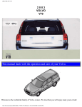
pg. 26 Daytime running lights, Tailgate wiper/washer (wagons)
Automatic daytime running lights
Screw A in the illustration (available on U.S. models only) is used to control the automatic daytime
running lights when the headlight switch is in position 0.
The low beams, tail lights, parking lights and license plates lights will come on automatically when the
ignition is switched on.
To adjust, press in the screw with a small screwdriver and turn to one of the following positions:
Automatic daytime running lights
file:///K|/ownersdocs/1999/1999_SV70/99sv70_022.htm (7 of 8)12/30/2006 3:36:49 PM
1999 S70 & V70
Automatic daytime running lights
The daytime running lights will also function when the headlight switch is in position
is in this position.
and switch A
All lights off (daytime running light function disabled)
NOTE: The daytime running light function may only be disabled (turned off) in the U.S. - Canadian law
mandates the use of daytime running lights.
Tailgate wiper/washer (wagons)
Tailgate window wiper/washer The tailgate window wiper/washer is operated by a switch at the end of
the wiper level.
1. The wiper operates continuously.
2. Intermittent position: the wiper strokes approximately every 10 seconds.
3. Tailgate washer (note that the wiper also operates when this button is depressed): after the button is
released the wiper strokes 2-3 additional times before stopping.
Contents | Top of Page
file:///K|/ownersdocs/1999/1999_SV70/99sv70_022.htm (8 of 8)12/30/2006 3:36:49 PM
1999 S70 & V70
pg. 27 Clock, Ambient temperature sensor (certain models)
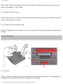
Resetting the clock
The digital clock can be reset by pressing one of the two buttons (A and B) with a pointed object such as
the tip of a pen.
h = hours
m = minutes
Maintain the pressure on the buttons for more than four seconds to change the time more quickly.
NOTE: All digital displays will go off 30 minutes after the ignition has been switched off. To view
these displays again, turn the ignition key to the position I.
Ambient temperature sensor
This sensor indicates the temperature slightly above the road surface and represents air temperature
where road icing may occur. An amber warning lamp (C) lights up when the temperature is in the range
of 23 - 36° F (-5 - +2° C). Please note that this lamp does not indicate a fault with your car.
At low speeds or when the car is not moving, the temperature readings may be slightly higher than the
actual ambient temperature due to the heat generated by the engine.
Display alternatives
If buttons A and B are pressed down simultaneously, it is possible to shift between four different display
alternatives:
Press 1st time: 12 hour clock and °F
Press 2nd time: 24 hour clock and °F
Press 3rd time: 12 hour clock and °C
Press 4th time: 24 hour clock and °C
file:///K|/ownersdocs/1999/1999_SV70/99sv70_027.htm (1 of 5)12/30/2006 3:36:49 PM
1999 S70 & V70
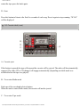
pg. 28 Trip computer (certain models)
Trip computer
The trip computer offers six functions which are presented in a single display. The cursor indicates the
selected function. The trip computer's clock is shown permanently in the left-hand field. Refer to the
previous page for more detailed information regarding the clock function.
The following data is monitored by the computer:
●
●
●
●
●
●
Average speed
Current fuel consumption
Average fuel consumption
Ambient temperature*
Tripmeter
Driving distance on current fuel reserve
* Warning light A in the illustration above. See page 30 for more details.
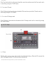
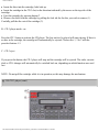
Trip computer controls
Select one of the trip computer's six functions by using control B. The Reset button (C) is used to reset
the following functions:
● Average speed
● Average fuel consumption
file:///K|/ownersdocs/1999/1999_SV70/99sv70_027.htm (2 of 5)12/30/2006 3:36:49 PM
1999 S70 & V70
Trip meter
Rotate the control to the required position and press the button for at least two seconds to reset the
selected function.
●
NOTE: If pressure is maintained on the button for another three seconds, all three of the functions
mentioned above will be reset.
pg. 29 Trip computer (certain models) (cont.)
Average speed Ø mph (Canada: km/h)
Average speed since the function was last reset. When the ignition is switched off, the average speed is
stored in memory and is used as the basis for the new figure when the engine is started again. It can be
reset by pressing the reset button on the trip computer control.
Current fuel consumption mpg (Canada: L/100 km)
Continuous information on current fuel consumption, calculated once per second. When the car is not
moving, the display shows "---".
Average fuel consumption Ø mpg (Canada: L/100 km)
Average fuel consumption since the function was last reset. When the ignition is switched off, the
average fuel consumption figure is stored in memory and remains in memory until it is reset using the
button on the trip computer control.
file:///K|/ownersdocs/1999/1999_SV70/99sv70_027.htm (3 of 5)12/30/2006 3:36:49 PM
1999 S70 & V70
pg. 30 Trip computer (certain models) (cont.)
Ambient temperature
Shows the ambient temperature just above the road surface while driving. When the temperature is in the
range 23 - 36° F (-5 - +2° C), the ambient temperature sensor activates an amber warning light. Please
note that this lamp does not indicate a fault with your car.
At low speeds or when the car is not moving, the temperature readings may be slightly higher than the
actual ambient temperature due to the heat generated by the engine.
Tripmeter in miles (Canada: km)
Shows the distance driven since the function was last reset. This value is stored in memory until it is
reset using the reset button on the trip computer control.
Driving distance on current fuel reserve
mile 0 (Canada: km)
Shows the distance which can be driven on the fuel remaining in the tank, calculated on the basis of the
average fuel consumption during the last 12 miles (20 km) dirven and the amount of fuel remaining in
the tank at the time of the reading.
When the quantity of fuel drops to below approximately 1.8 US gals. (8 liters), a warning light in the
instrument panel comes on. When the driving distance on the current fuel reserve is less than 12 miles
(20 km), the display shows "—".
file:///K|/ownersdocs/1999/1999_SV70/99sv70_027.htm (4 of 5)12/30/2006 3:36:49 PM
1999 S70 & V70
Contents | Top of Page
file:///K|/ownersdocs/1999/1999_SV70/99sv70_027.htm (5 of 5)12/30/2006 3:36:49 PM
1999 S70 & V70
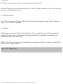
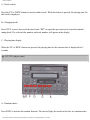
pg. 31 Cruise control
Cruise control
The cruise control switches are located on the turn signal lever.
To engage and set the desired speed:
1. Set switch (B) to ON.
2. Accelerate to the desired cruise speed.
3. Press the + or - area of the SET button (A) to set the desired speed.
NOTE: The cruise control cannot be engaged at speeds below 22 mph (35 km).
Braking
This will automatically disengage the cruise control. The previously selected cruise speed is retained in
the memory and by momentarily setting the switch to RESUME position, that speed will be re-engaged.
If the cruise control is already engaged, the cruising speed can be increased or decreased by depressing
the SET button (A) towards either + or -. One short press on the button corresponds to a speed change of
approx. 1 mph (1.6 km/h). When thebutton is released, the vehicle will maintain the current speed.
If actual speed falls below 70% of the set speed or if the wheels spin or lock, the cruise control will
disengage automatically.
NOTE: (AUTOMATIC TRANSMISSION)
When driving up steep hills with the cruise control engaged, the transmission may shift intermittently.
file:///K|/ownersdocs/1999/1999_SV70/99sv70_031.htm (1 of 6)12/30/2006 3:36:50 PM
1999 S70 & V70
Acceleration
Momentary acceleration, such as for passing, does not interrupt cruise control operation. The previously
selected speed will be maintained without having to set the switch to RESUME.
To disengage the cruise control system :
Set switch (B) to OFF, depress the brake pedal or move the gear selector to position N. Switching off the
starting (ignition) switch will automatically disengage the cruise control system.
On cars equipped with manual transmissions, the cruise control can also be disengaged by depressing
the clutch.
WARNING! The cruise control should not be used in heavy traffic or when driving on wet or slippery
roads. Do not use or resume cruise control in reverse gear.
NOTE: When the ignition is switched off, any information stored in the cruise control memory is erased.
pg. 32 Heated front seats (certain models), Parking brake
Heated front seats
file:///K|/ownersdocs/1999/1999_SV70/99sv70_031.htm (2 of 6)12/30/2006 3:36:50 PM
1999 S70 & V70
The heated front seats can be switched on and off as required. When switched on, the system senses the
ambient temperature and regulates the level of heat applied. When the optimum temperature is reached,
the heating switches off automatically. While driving, the seat heating for the passenger seat should be
switched off when the seat is not occupied.
Parking brake lever
The lever is situated between the front seats.
The brake is applied to the rear wheels.
WARNING! Always use the parking brake (hand brake) when parking. On hills, also turn the front
wheels toward the curb.
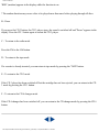
pg. 33 Ashtrays, Auxiliary socket
file:///K|/ownersdocs/1999/1999_SV70/99sv70_031.htm (3 of 6)12/30/2006 3:36:50 PM
1999 S70 & V70
Front ashtray
To open the front ashtray, press lightly on the panel.
To empty the front ashtray:
●
●
Put the gear selector (aut. transmission) in position L.
Grasp the front edge of the ashtray and pull it straight out.
Rear seat auxiliary socket* and ashtray
Rear ashtrays
file:///K|/ownersdocs/1999/1999_SV70/99sv70_031.htm (4 of 6)12/30/2006 3:36:50 PM
1999 S70 & V70
To open the rear ash tray, pull it straight out.
To empty the rear ash tray, pull it out, lift up the rear edge and remove.
Front auxiliary socket*
Auxiliary socket
This 12 volt socket can be used to plug in certain accessories such as cellular telephones, etc. The key
must be in position I (or higher) for the auxiliary socket to function.
NOTE: The "OBD II" terminal, a connector for diagnostic equipment, is located under the cover of the
storage compartment between the front seats. This terminal is intended for use by authorized service
technicians only.
* The auxiliary sockets can also be used as cigarette lighters, which are available at your Volvo retailer.
pg. 34 Steering wheel adjustment
file:///K|/ownersdocs/1999/1999_SV70/99sv70_031.htm (5 of 6)12/30/2006 3:36:50 PM
1999 S70 & V70
Steering wheel adjustment
Both the height and the reach of the steering wheel can be adjusted to a comfortable position for the
driver. Pull down the lever on the left of the steering column. Adjust the steering wheel to a suitable
position and press the lever back intoplace to lock the steering wheel in the new position. Check that the
steering wheel is locked in the new position.
WARNING! Never adjust the steering wheel while
driving.
Contents | Top of Page
file:///K|/ownersdocs/1999/1999_SV70/99sv70_031.htm (6 of 6)12/30/2006 3:36:50 PM
1999 S70 & V70
pg. 35 Heating, ventilation and air conditioning
Heating and air conditioning
Your Volvo is equipped with a heating system combined with air conditioning. Depending on which
function you select, warm or cool/cold air is distributed to the different parts of the passenger
compartment. A slight amount of condensation may beemitted from the air vents when the air
conditioning is initially switched on. This can occur when both humidity and ambient temperature are
high and is normal.
Air mix (fresh air)
The center panel vents have an air mix function which allows fresh air to enter the passenger
compartment when the vents are open (position B). This function is designed to allow you to direct cool
air toward your face while directing warmer airto the rest of the passenger compartment.
To warm/cool the compartment as quickly as possible, the air mix control should be in the closed
position.
file:///K|/ownersdocs/1999/1999_SV70/99sv70_035.htm (1 of 11)12/30/2006 3:36:53 PM
1999 S70 & V70
Air vents (dash)
A Closed
B Open
C Directing air flow horizontally
D Directing air flow vertically
Refrigerant
Volvo cares about the environment. The air conditioning system in your car contains a CFC-free
refrigerant - R134a. This substance will not deplete the ozone layer. The system contains 1.63 lbs (0.75
kg) R134a and uses ZXL 100PG (type PAG) oil.
NOTE: All maintenance on the climate control systems should be carried out by an authorized Volvo
service technician only.
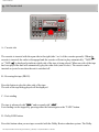
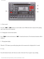
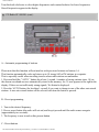
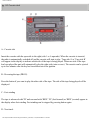
pg. 36 Heating, ventilation and air conditioning (standard unit)
file:///K|/ownersdocs/1999/1999_SV70/99sv70_035.htm (2 of 11)12/30/2006 3:36:53 PM
1999 S70 & V70
Temperature dial
Driver's side
Set desired temperature
Function selector
Set desired function
Temperature dial
Passenger's side
Set desired temperature
Blower
Turn the control clockwise to increase blower speed. The blower is OFF if the control is in the 0
position.
Recirculation
Air in the passenger compartment recirculates (no fresh air enters the car). The light is ON when the
function is engaged. It should not be used for more than 15 minutes.
AC
The A/C system is ON when the light is ON*.
* When the function selector is in the defrost setting, the A/C will automatically be ON if recirculation is
not on and the blower control is not in position 0.
file:///K|/ownersdocs/1999/1999_SV70/99sv70_035.htm (3 of 11)12/30/2006 3:36:53 PM
1999 S70 & V70
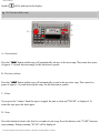
Function selector
Air through panel vents
Defrost. Air to windshield and side windows.
Air to floor, windshield and side windows.
Air through floor vents.
Bi-level. Air through floor and panel vents.
NOTE: If your windows begin to fog or mist, check that the recirculation function is NOT engaged.
Faults in the A/C system
The RECIRCULATION and AC lights will flash for approximately 20 seconds if a fault is detected in
the A/C ssystem.
If this flashing recurs the next time the system is switched on, the climate control nit should be checked
by an authorized Volvo retailer.
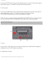
pg. 37 Heating, ventilation and air conditioning (standard unit) (cont.)
Maximum heating:
Close the center panel vents. When the passenger compartment has become sufficiently warm, set the
blower control to the fourth position, adjust the temperature and open the side air vents.
Maximum cooling:
file:///K|/ownersdocs/1999/1999_SV70/99sv70_035.htm (4 of 11)12/30/2006 3:36:53 PM
1999 S70 & V70
Open the vents. The A/C system should be ON.
Adjust the temperature with the temperature selectors to raise the temperature if necessary.
The recirculation function should not be used for more than 15 minutes.
To demist/defrost the windows:
Set the function selector to
and the blower control to the highest position. The A/C will be ON if
recirculation is not on. When the windows have cleared, set the blower control to the second position
and the function selector to the desired position. Always keep the air intake grille at the base of the
windshield under the rear edge of the hood free of snow.
Additional information
The air conditioning system will function best if it is always left on.
● Water under the vehicle in hot weather can be the result of condensation from the air conditioning
system and is quite normal.
● The air conditioning system functions only at temperatures above 32° F (0° C).
● Use the RECIRCULATION function if the outside air is contaminated with exhaust gases, smoke, etc
or to heat/cool the car quickly. In this position, very little air is drawn into the passenger compartment
from the outside. Do not leave the system in this mode for more than 10-15 minutes since the air inside
the car will become stale. The temperature can be controlled with the temperature selectors.
● If the panel vents are open, a certain amount of air will always flow through, regardless of the position
the function selector is in. To increase the flow of air to either the floor or the windows, close the panel
vents and open the outer vents .
●
file:///K|/ownersdocs/1999/1999_SV70/99sv70_035.htm (5 of 11)12/30/2006 3:36:53 PM
1999 S70 & V70
The panel vents may emit some condensation when the air conditioning is initially switched on and is
quite normal. This may occur if the ambient temperature and humidity are high.
● The air conditioning is momentarily disengaged during full-throttle acceleration.
●
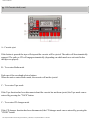
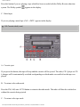
pg. 38 Heating, ventilation and air conditioning (Electronic Climate Control) - option
Temperature dial
Driver's side
Set desired temperature
Function selector
Set desired function
Temperature dial
Passenger's side
Set desired temperature
Blower
AUT=Blower speed automatically regulated.
0 = OFF
Move the knob to the right to increase blower speed.
RECIRCULATION
Air in the passenger compartment recirculates (no fresh air enters the car). The amber light in the righthand button is ON when the function is engaged. It should not be used for more than 15 minutes*. The
file:///K|/ownersdocs/1999/1999_SV70/99sv70_035.htm (6 of 11)12/30/2006 3:36:53 PM
1999 S70 & V70
green light in the left-hand button indicates that outside air can enter the passenger compartment.
AC ON/OFF
The light in the buttons indicate if the A/C is off or on**
**When the function selector is in the defrost setting, the A/C system is ON and the blower will function
at its highest speed if it is in the AUT position.
Function selector
AUT Air distribution automatically regulated
Air through panel vents
Defrost. Air to windshield and side windows. Recirculation will not function regardless of button
position.
Air to floor, windshield and side windows.
Air through floor vents.
Bi-level. Air through floor and panel vents.
* Pressing the ON section of the button for more than 3 seconds activates a timer function. Recirculation
will then always operate for 5 minutes periods, after which the button will flash to indicate that
Recirculation has automatically switched off. Pressing the OFF button at any time during 5 minute
period will allow fresh air into t he passenger compartment. Press the ON button again for more than 3
seconds to return the button to its original function (i.e., Recirculation will remain on until the OFF
button is pressed).
pg. 39 Heating, ventilation and air conditioning (Electronic Climate Control) - option (cont.)
Automatic setting
file:///K|/ownersdocs/1999/1999_SV70/99sv70_035.htm (7 of 11)12/30/2006 3:36:53 PM
1999 S70 & V70
Set the mode selector to AUT and select the desired temperature. If the driver's side temperature selector
is set to either the max heating or max cooling position, the blower will run at its maximum speed.
Optimum defrosting
Set the function selector to
and move the blower control to the position AUT (as far to the left as
possible). The A/C system will be on at this time regardless of the A/C button's position and the blower
will run at its maximum speed. When the windows have cleared, set thefunction selector in the AUT
position.
Additional information
The air conditioning system will function best if used regularly (at least once a month).
● Always keep the air intake grille at the base of the windshield under the rear edge of the hood free of
snow.
● Water under the vehicle in hot weather can be the result of condensation from the air conditioning
system and is quite normal.
● The air conditioning is disengaged when the blower is set at 0 and the speed of the vehicle is less than
20 mph (30 kn/h).
● The air conditioning system functions only at temperatures above 32° F (0° C).
● Recirculation : Use this function if the outside air is contaminated with exhaust gases, smoke, etc. or
to heat/cool the car quickly. When Recirculation is activated, very little air drawn into the passenger
compartment from the outside.
If your windows begin to fog or mist, check that the recirculation function is NOT engaged.
●
file:///K|/ownersdocs/1999/1999_SV70/99sv70_035.htm (8 of 11)12/30/2006 3:36:53 PM
1999 S70 & V70
NOTE: When driving with the sun roof or windows open, to help maintain stable passenger
compartment temperature, use the blower control to manually regulate the blower speed.
If the panel vents are open, a certain amount of air will always flow through, regardless of the position
the function dial is in. To increase the flow of air to either the floor or the windows, close the panel vents
and open the outer vents
● The panel vents may emit some condensation when the air conditioning is initially switched on and is
quite normal.
This may occur if the ambient temperature and humidity are high.
● The sunlight sensor (located at the top center of the dashboard) should not be covered in any way as
this could cause incorrect information to be sent to the ECC system.
● The air conditioning is momentarily disengaged during full-throttle acceleration.
●
Difficult weather conditions
When driving in very humid conditions, heavy rain, sleet, etc., it may be better to use the manual rather
than the automatic setting to defrost the windows. Set the mode selector to "Defrost"
floor" and the fan speed to midrange. Also shut the middle air vents.
or "Defrost/
Faults in the ECC system
The RECIRCULATION ON and AC OFF lights will flash for approximately 20 seconds if a fault is
detected in the ECC system.
If this flashing recurs the next time the system is switched on, the climate control unit should be checked
by an authorized Volvo retailer.
pg. 40 Electrically-operated windows
file:///K|/ownersdocs/1999/1999_SV70/99sv70_035.htm (9 of 11)12/30/2006 3:36:53 PM
1999 S70 & V70
A- Left front, B- right front, C- left rear, D- right rear,
E- Cutout switch, rear windows, F- central locking button (see page 43).
Electrically-operated windows
The electrically-operated windows are controlled by switches in the driver's door as shown in the
illustration above. The starting (ignition) switch must be ON (intermediate position I) for the electricallyoperated windows to function.
To lower : press down on the front edge of the button
To raise : pull up on the front edge of the button.
NOTE:
● Auto-down function (driver's window only): The window can be opened completely by pressing the
front part of the switch lightly and releasing it immediately. The window can be stopped by pressing the
button again. If the button is held down, the window will be lowered until the button is released.
● The power window motors have an overload protecting circuit breaker which is activated when an
object blocks a window. Should this occur, remove the object and wait 20 seconds for the circuit breaker
to reset. The power windows should then function.
Cut-out switch for rear windows
If your car is equipped with electrically operated rear door windows, this function can be disabled by a
file:///K|/ownersdocs/1999/1999_SV70/99sv70_035.htm (10 of 11)12/30/2006 3:36:53 PM
1999 S70 & V70
switch located on the driver's door (see illustration).
ON The rear door windows can be raised or lowered with the respective door switches as well as with
the switches on the driver's door armrest.
OFF The rear door windows cannot be raised or lowered with the respective door switches but instead
only with the corresponding switches on the driver's door armrest.
WARNING! Remove the starting (ignition) key when children are left unattended in the
vehicle.
Make sure that children's hands are clear before raising the windows.
Contents | Top of Page
file:///K|/ownersdocs/1999/1999_SV70/99sv70_035.htm (11 of 11)12/30/2006 3:36:53 PM
1999 S70 & V70
Chapter 3 - Body and interior
pg. 41 Body and interior
Body and interior
The seats, sun roof, mirrors, etc. are described on the following pages.
Page No. Subject
pg. 42
Keys
pg. 43
Doors and locks
pg. 44
Remote keyless entry system
pg. 45
Alarm
pg. 47
Trunk/tailgate
pg. 48
Child safety locks
pg. 49-50 Front seats
pg. 50
Rear/side view mirrors
pg. 51
Interior lights, Vanity mirror
pg. 52
Sun roof
pg. 53
Hood
pg. 54
Storage compartments
pg. 55
Trunk light, Spare tire, Jack
pg. 56
Cargo space lighting, Spare tire, Jack (wagon)
pg. 57
Folding rear seat (sedan)
pg. 58-59 Folding rear seat (wagon)
pg. 59
Removing seat cushions
pg. 60
Concealed storage bin/Bumper cover (wagon), Avoiding battery
drain
pg. 61
Luggage net/Side cargo net (wagon)
pg. 62
Securing cargo
file:///K|/ownersdocs/1999/1999_SV70/99sv70_041.htm (1 of 6)12/30/2006 3:36:55 PM
1999 S70 & V70
pg. 63
Folding front seat, Long load storage
pg. 42 Keys
Master key
This key operates all locks (ignition switch/steering wheel lock, driver's door, trunk/tailgate and glove
compartment).
Service key
This key operates the driver's door and the ignition switch/steering wheel lock.
NOTE:
An an added anti-theft measure, new keys have been developed which may take slightly longer to
copy or replace if the original keys are misplaced. Duplicate keys may be ordered from your Volvo
retailer.
● The key number codes are stamped on a separate tag supplied with the keys. This tag should be
●
file:///K|/ownersdocs/1999/1999_SV70/99sv70_041.htm (2 of 6)12/30/2006 3:36:55 PM
1999 S70 & V70
separated from the key ring and kept in a safe place.
Immobilizer (start inhibitor)
Each of the keys supplied with your car contains a coded transmitter and receiver (transponder). The
code in the key is transmitted to an antenna in the ignition switch where it is compared to the code stored
in the start inhibitor module. The car can only be started if a properly coded key is used.
If you misplace a key, take the other keys to an authorized Volvo retailer. The existing code in the start
inhibitor module and all the keys will be erased as an antitheft measure and a new code will be
programmed in.
NOTE:
Not more than one of the keys for you car should be kept on the same key ring. This could cause
conflicting signals to be transmitted to the ignition switch, making it imposible to start the car.
This device complies with FCC rules Part 15. Operation is subject to the following two conditions: (1)
This device may not cause harmful interference and (2) this device must accept any interference that
may be received, including interference that may cause undesired operation.
pg. 43 Doors and Locks
Doors and locks
Your car is equipped with a two door operated central locking system.
The key, used on the driver's doors, the remote control, or central locking button, will lock/unlock all
doors, trunk/tailgate.
Turn the key once to unlock the driver's door only.
Turn the key again (within 10 seconds) to unlock all doors, trunk/tailgate.
One turn with the key towards lock in the drivers door locks all doors, trunk/tailgate.
Use the switch on the front door armrests to lock/unlock the car from the inside.
Check the action of the buttons on the other doors to verify their correct function (lock/unlock).
WARNING! The doors should not be locked while driving. In case of an accident, this may hinder
rapid access to the occupants of the vehicle. (Also see information on "Child safety locks".)
file:///K|/ownersdocs/1999/1999_SV70/99sv70_041.htm (3 of 6)12/30/2006 3:36:55 PM
1999 S70 & V70
Central locking button (on both front doors)
Central locking button
The central locking buttons on both front door armrests can be used to lock or unlock all doors and trunk/
tailgate and set the alram if your car is so equipped. This switch functions even if a door/trunk/tailgate is
open.
Lock: Press the left side of the button
Unlock: Press the right side of the button
NOTE: To help prevent accidentally locking the keys in the car, the central locking system is designed
to unlock the driver's door immediately if the key is left in the ignition switch and the car is locked using
the lock button on the door. A sound from the lock will be audible at this time.
Please note that this function will not unlock the doors if the engine is running.
pg. 44 Remote keyless entry system
file:///K|/ownersdocs/1999/1999_SV70/99sv70_041.htm (4 of 6)12/30/2006 3:36:55 PM
1999 S70 & V70
Remote keyless entry system
Your car is equipped with a remote control transmitter. This transmitter uses a readio frequency which
will allow “keyless” entry into the passenger compartment or the trunk. You will be supplied with two
coded key ring transmitters, which willenable you to lock/unlock all doors and the trunk/tailgate from a
distance of 10-15 feet (3-5 meters).
The car can also be locked/unlocked with the key.
As an extra security precaution in certain situations (valet parking,etc.), Volvo recommends that the
transmitter not be included when the keys are given to anyone. The service key can be used instead. If
one of transmitters is misplaced , contact the nearest authorized Volvo retailer for assistance.
file:///K|/ownersdocs/1999/1999_SV70/99sv70_041.htm (5 of 6)12/30/2006 3:36:55 PM
1999 S70 & V70
Using the remote control
* Press the LOCK button once to lock all doors and trunk/tailgate.
* Press the UNLOCK button once to unlock the driver’s door only. Press this button again (within 10
seconds) to unlock all doors, trunk/tailgate.
* Press the OPEN TRUNK/TAILGATE button twice within 3 seconds to pop open the trunk or unlock
the tailgate
This device complies with FCC rules Part 15. Operation is subject to the following two conditions: (1)
This device may not cause harmful interference and (2) this device must accept any interference that
may be received, including interferencethat may cause undesired operation.
NOTE: If only the driver’s door is unlocked, the lock will automatically reengage (re-lock) and the
alarm will reset after 2 minutes unless the door has been opened.
The lock/unlock and alarm features can also be utilized by using the keys. See section: Doors and Locks
on page 43.
If the alarm LED glows coninuously for 5 seconds, this indicates a fault in the system or that a door is
not properly closed.
WARNING! Volvo does not recommend using the transmitter to lock the doors from inside the car.
On cars equipped with an alarm, the alarm would be activated and would sound when one of the doors
is opened. The doors must not be locked using the remote transmitter while the vehicle is occupied. In
case of an accident, this may hinder rapid access to the occupants of the vehicle. The alarm will also
sound on models equipped with this feature.
NOTE : To avoid leaving your keys in the car, make a habit of always locking the car with the remote
control.
Contents | Top of Page
file:///K|/ownersdocs/1999/1999_SV70/99sv70_041.htm (6 of 6)12/30/2006 3:36:55 PM
1999 S70 & V70
pg. 45 Alarm (certain models)
LED alarm status indicator
Alarm
The radio signal emitted from the transmitter, which is used to set/unset the alarm, is a “rolling code”
signal. This means that the signal is changed randomly for each transmission and is intended to help
prevent unauthorized recording of the code.
When armed (set), the alarm continuously monitors a number of points on the car. The following
conditions will set off the alarm:
* The hood is opened
* The trunk/tailgate is opened
* A door is opened
* The ignition switch is tampered with
* The car is lifted or towed (if the car is equipped with the optional inclination sensor)
* The battery is disconnected (if the car is equipped with the optional backup battery siren). The alarm
will sound for ten 30 second intervals, with a 5 second pause between intervals. This function cannot be
interrupted.
Arming (setting) the alarm
Press the LOCK button on the remote control, lock the car using the key in the driver’s door or press the
central lock button on one of the front doors with the door open. One long flash of the turn signals will
confirm that the alarm is set.
Disarming the alarm
file:///K|/ownersdocs/1999/1999_SV70/99sv70_045.htm (1 of 8)12/30/2006 3:36:56 PM
1999 S70 & V70
Press the UNLOCK button on the remote control or unlock the doors with the key.
Turning off (stopping) the alarm
If the alarm is sounding, it can be stopped by pressing the UNLOCK button on the remote control or by
unlocking the driver’s door with the key.
If the alarm is stopped with the remote control, this will be confirmed by two short flashes from the turn
signals.
Visual alarm signal
The visual alarm signal is given by flashing all turn signals and turning on the interior lighting for 5
minutes.
Audible alarm signal
An audible alarm signal is given either by a separate alarm horn or by the optional back-up sire. One
alarm cycle lasts for 30 seconds.
“Panic “ function
In an emergency situation, this feature can be used to attract attention.
file:///K|/ownersdocs/1999/1999_SV70/99sv70_045.htm (2 of 8)12/30/2006 3:36:56 PM
1999 S70 & V70
Activate the “panic” function by pressing the red panic button on the remote control for at least 3
seconds or by pressing this button twice within 3 seconds. The turn signals will flash, the interior lights
will go on and the alarm will sound.
The function can be turned off by pressing any of the buttons on the remote control or will stop
automatically after 25 seconds.
NOTE: This button will NOT unlock the car.
pg. 46 Alarm
LED alarm status signals
The status of the alarm system is indicated by the red LED at the top center of the dash:
* LED off - the alarm is not armed (set)
* LED flashes once per second - the alarm is armed (set)
* LED flashes rapidly before the ignition is switched on - the alarm has been triggered.
* LED flashed rapidly for 15 seconds after the ignition has been switched on - a fault has been detected
in the alarm system.
Contact a Volvo retailer.
Automatic reset function
If only the driver’s door is unlocked with the remote control, the lock will automatically reengage (relock) and the alarm will reset after 2 minutes unless the door has been opened.
Temporarily disconnecting the alarm sensor(s)
In certain situations it may be desirable to disconnect the optional alarm sensor, particularly the
inclination sensor, if, for example, you drive your car onto a ferry where the rocking of the boat could
trigger the alarm. To temporarily disconnect the sensor(s) from the alarm system:
<* With all doors closed, switch off the ignition and remove the key from the ignition switch
* Press the locking (left) side of the central locking button on the driver’s door for at least 3 seconds.
* The doors will first lock and then unlock after 3 seconds to confirm that the sensors have been
file:///K|/ownersdocs/1999/1999_SV70/99sv70_045.htm (3 of 8)12/30/2006 3:36:56 PM
1999 S70 & V70
disconnected.
The car can then be locked in the usual way to set the alarm.
NOTE: The sensors will automatically be reconnected to the alarm system the next time the ignition is
switched on.
Batteries
Each remote transmitter is powered by a three volt battery, type CARE. If the range of the transmitter is
noticeably reduced, this indicates that the battery is weak and should be replaced.
Replacement: Remove the battery cover on the back of the transmitter with a coin. Replace the battery.
Reinstall the cover, making sure it is secured tightly to help protect the transmitter.
CAUTION: Do not attempt to service or repair any components of the alarm system yourself. This
should only be done by an authorized Volvo retailer.
pg. 47 Trunk/Tailgate
file:///K|/ownersdocs/1999/1999_SV70/99sv70_045.htm (4 of 8)12/30/2006 3:36:56 PM
1999 S70 & V70
Opening/unlocking the trunk/tailgate
The trunk/tailgate locks are incorporated in the central locking system and are locked or unlocked when
the driver's door is locked/unlocked.
The trunk/tailgate can be opened by:
●
●
●
Pressing the button on the remote control (A) twice *
Using the master key in the trunk/tailgate ** lock
Using the trunk/tailgate control on the driver's door (B) *
* The tailgate will be unlocked only, not opened.
** The master key should not be used to unlock the tailgate on models equipped with the tailgate lock
button. This will trigger the alarm.
Refer to page 44 for information on the remote control locking system.
Disconnecting the trunk lock
The trunk lock can also be disconnected from the central locking system by turning the key
counterclockwise as shown below:
Withdraw the key in the horizontal position ***
file:///K|/ownersdocs/1999/1999_SV70/99sv70_045.htm (5 of 8)12/30/2006 3:36:56 PM
1999 S70 & V70
The trunk is now always locked. The optional folding rear seatback can also be locked from the trunk
(see page 57). This feature can be used for e.g., valet parking. If you give only the service key to the
driver, it will not be possible to gain access to the trunk. Please be aware that this setting may preclude
access to the spare tire and jack.
To reconnect the lock to the central locking system:
Withdraw the key in the vertical position
*** In this position, the trunk cannot be opened with the control on the driver's door or the remote
control.
Unlocking/opening tailgate from the inside
Tailgate lock button (certain models)
If the doors and tailgate are locked, the tailgate can be unlocked from the inside by pulling up the lock
button (see illustration). This unlocks the tailgate only. Please note that this button will only function if
the child safety lock in the tailgate is disengaged (see page 48) .
file:///K|/ownersdocs/1999/1999_SV70/99sv70_045.htm (6 of 8)12/30/2006 3:36:56 PM
1999 S70 & V70
WARNING! Do not drive with the tailgate open! Poisonous exhaust gases may enter via the open
tailgate.
pg. 48 Child safety locks (sedan/wagon)
Location and setting of child safety lock
Child safety locks (sedan/wagon)
The controls are located on the rear door jams.
A The door cannot be opened from the inside. Normal operation from the outside.
B The door lock lock functions normally.
WARNING! Remember, in the event of an accident, the rear seat passengers cannot open the doors
from the inside with the buttons in position A.
file:///K|/ownersdocs/1999/1999_SV70/99sv70_045.htm (7 of 8)12/30/2006 3:36:56 PM
1999 S70 & V70
Child safety lock in tailgate
Child safety lock (wagon)
The tailgate incorporates a safety catch which is located to the side of the lock.
A The tailgate cannot be opened from the inside.
B The tailgate functions normally.
NOTE: You must use the end of a key, screwdriver, etc. to move the child safety lock.
WARNING! Remember, in the event of an accident, the tailgate cannot be opened from the inside
when the safety catch is in position A.
Contents | Top of Page
file:///K|/ownersdocs/1999/1999_SV70/99sv70_045.htm (8 of 8)12/30/2006 3:36:56 PM
1999 S70 & V70
pg. 49 Front seats
1 Height adjustment (manual)
The front section of both front seats can be adjusted to eight different height settings and the rear section
of both seats can be adjusted to nine different height settings.
Forward lever = adjustment of front section
Rear lever = adjustment of rear section
WARNING! Do not adjust the seat while driving. The seat should be adjusted so that the brake pedal
can be depressed fully. In addition, position the seat as far rearward as comfort and control allow. The
seat rails on the floor must not be obstructedin any way when the seat is moved.
2 Forward-rearward seat adjustment (manual)
Pull the control upward, then slide the seat forward or rearward to the desired position. Make sure that
the seat is properly secured when you release the control.
Folding front seat
The passenger's seat backrest has a quick forward release mechanism which can be used when long
loads are carried. See page 63.
3 Backrest tilt (manual)
Rotate the control counterclockwise to tilt the backrest rearward and clockwise to tilt the backrest
forward.
4 Lumbar support *
file:///K|/ownersdocs/1999/1999_SV70/99sv70_049.htm (1 of 9)12/30/2006 3:36:57 PM
1999 S70 & V70
Firm: turn clockwise
Soft: turn counter-clockwise.
* Driver's seat only on certain models
Electrically operated seats with memory function (certain models)
Power seat control panel
A Seat front (raise/lower)
B Forward - rearward
C Seat rear (raise/lower)
D Backrest tilt
WARNING! The power seats are operable with the ignition OFF. Therefore, children should never be
left unattended in the car.
file:///K|/ownersdocs/1999/1999_SV70/99sv70_049.htm (2 of 9)12/30/2006 3:36:57 PM
1999 S70 & V70
Movement of the seat can be STOPPED at any time by pressing any button on the power seat control
panel.
To adjust the passenger's seat, the ignition key must be in position I or II.
Refer to the following page for information on programming the memory function.
pg. 50 Electrically operated driver's seat, Rear/side-view mirrors
Programming the memory
Three seat positions can be programmed. To program a seat position:
1 Adjust the seat to the desired position.
2 Depress the MEM button.
3 Press button 1 to program the current position of the seat.
Buttons 2 and 3 can be programmed in the same way. To move the seat to a programmed position,
depress button 1, 2 or 3 until the seat stops. If the button is released before the seat has the reached the
programmed position, it will stop as a safety precaution.
NOTE: The seat has an overload protector which engages if an object blocks the movement of the seat.
If this happens, remove the object and wait 20 seconds before operating the seat again.
file:///K|/ownersdocs/1999/1999_SV70/99sv70_049.htm (3 of 9)12/30/2006 3:36:57 PM
1999 S70 & V70
Rear-view mirror
A Normal position
B Night position, reduces glare from following headlights
CAUTION: Never use ice scrapers made of metal as they can easily scratch the mirror
surface
WARNING! The mirrors should always be adjusted prior to driving. Objects seen in the wide-angle
right side-view mirror are closer than they appear to be.
Adjustment control
file:///K|/ownersdocs/1999/1999_SV70/99sv70_049.htm (4 of 9)12/30/2006 3:36:57 PM
1999 S70 & V70
Electrically operated side-view mirrors
The control switches are located in the center console, beside the parking brake.
A Lateral adjustment
B Vertical adjustment
WARNING! The mirrors should always be adjusted prior to driving. Objects seen in the wide-angle
right side-view mirror are closer than they appear to be.
pg. 51 Interior lights, Vanity mirror
Front courtesy lights
The front courtesy lighting consists of two reading lights for the front seat occupants.
Front and rear reading lights always on
0 Front and rear reading lights always off
Front and rear reading lights come on when a door is opened
Left or right reading light illuminates if the center switch is in position
.
The courtesy lights remain illuminated for 30 seconds after the doors have been closed but will be
switched off if the ignition is turned on or the doors are locked.
file:///K|/ownersdocs/1999/1999_SV70/99sv70_049.htm (5 of 9)12/30/2006 3:36:57 PM
1999 S70 & V70
Reading lights, rear seat
There are two reading lights for the rear seat passengers. These are turned on/off by using the adjacent
switches.
Light is on if the front switch is in position
Light turns on if any door is opened.
.
Vanity mirrors
The light illuminates when the cover is opened.
The driver's side vanity will only illuminate if the ignition key is in position I.
pg. 52 Sun roof (option)
file:///K|/ownersdocs/1999/1999_SV70/99sv70_049.htm (6 of 9)12/30/2006 3:36:57 PM
1999 S70 & V70
Sliding sun roof
Electrically-operated sun roof
The switch for operating the sun roof is located on the instrument panel. The starting (ignition) key must
first be turned to position II. On certain models, the sun roof is equipped with a one-touch, AUTO-open
function.
AUTO-open: Press the lower section of the switch once to automatically open the sun roof to the
"comfort position"*. Press again to open the sun roof completely. The AUTO-open function can be
stopped at any time by pressing the switch.
●
file:///K|/ownersdocs/1999/1999_SV70/99sv70_049.htm (7 of 9)12/30/2006 3:36:57 PM
1999 S70 & V70
Sun visor
To close the sun-roof : Depress the upper section of the switch until the sun roof has closed
completely .
● To open the rear edge of the sun roof (ventilation position) : With the sun roof closed, depress the
upper section of the switch. To close, depress the lower section of the switch until the sun roof has
closed completely.
● To slide open the sun roof: Depress the lower section of the switch until the sun roof has opened to
the position you prefer or hold the switch until the sun roof reaches the "comfort position"*. Depress the
lower section of the switch again to open the sun roof completely.
●
Sun visor: The sun roof also features a sliding sun visor. The visor slides back automatically when the
sun roof is opened and also slides back slightly when the sun roof is opened to the ventilation position.
The visor must be closed manually.
CAUTION: Do not close the sun visor when the sun roof is in the ventilation position as this could
damage the mechanism.
NOTE:
● The electrically-operated sun roof has an overload protecting circuit breaker (fuse no. 37) which is
activated when an object blocks the sun roof. Should this occur, remove the object and wait 20 seconds
for the circuit breaker to reset. The sun roof should then function normally. Also check fuse no. 35.
file:///K|/ownersdocs/1999/1999_SV70/99sv70_049.htm (8 of 9)12/30/2006 3:36:57 PM
1999 S70 & V70
WARNING! The sun roof must never be obstructed in any way when in
operation.
* A position where the sun roof is not quite fully open. This position helps alleviate "rumbling" wind
noise.
Contents | Top of Page
file:///K|/ownersdocs/1999/1999_SV70/99sv70_049.htm (9 of 9)12/30/2006 3:36:57 PM
1999 S70 & V70
pg. 53 Hood
To open the hood
●
●
●
Pull the lever located under the left side of the dash to release both hood catches.
Lift the hood slightly.
Pull the release control on the inside of the lower edge of the grille toward you and lift the hood.
WARNING! Check that the hood locks properly when
closed.
The hood normally opens to an angle of 57°. The hood can be opened to the vertical position by rotating the
hinge catches (see illustrations). The catches will return to their normal positions when the hood is closed.
file:///K|/ownersdocs/1999/1999_SV70/99sv70_053.htm (1 of 5)12/30/2006 3:36:57 PM
1999 S70 & V70
Ensure adequate clearance in low-roof garages to avoid damaging the hood.
pg. 54 Storage compartments
WARNING! Packages on the rear window shelf can obscure vision and may become dangerous projectiles
in the event of a sudden stop or an accident.
1 Glove compartment
2 Compartment in center console (certain models)
3 Pocket in seat front (certain models)
4 Clip for parking receipts
5 Compartment in door (certain models)
6 Compartment between front seats/Cup holder (certain models)
7 Pocket on rear of front seat
8 Compartment in hat shelf (sedan)
file:///K|/ownersdocs/1999/1999_SV70/99sv70_053.htm (2 of 5)12/30/2006 3:36:57 PM
1999 S70 & V70
pg. 55 Trunk light, Spare tire, Jack (sedan)
Trunk light
A Light always off.
B Light is on when trunk lid is opened.
Spare tire
The spare tire is located under the carpet in a special well under the floor of the trunk. The jack is placed
inside the wheel rim.
WARNING! Make sure that the jack is properly secured in the wheel rim with the securing bracket. The belt
must also be threaded though the slot in the securing bracket(see illustration) and properly fastened to help
keep the spare wheel/jack in place in the event of a sudden stop.
file:///K|/ownersdocs/1999/1999_SV70/99sv70_053.htm (3 of 5)12/30/2006 3:36:57 PM
1999 S70 & V70
NOTE: See pages 92-93 for information on how the jack should be used.
pg. 56 Cargo space lighting, Spare tire, Jack (wagon)
Cargo space lighting
There is an extra courtesy light at the rear of the cargo space.
1 The light is always OFF
2 Light comes on when the tailgate is opened
Spare tire and jack
file:///K|/ownersdocs/1999/1999_SV70/99sv70_053.htm (4 of 5)12/30/2006 3:36:57 PM
1999 S70 & V70
The spare tire and the jack are located beneath the floor mat in the large storage bin.
WARNING! Make sure that the jack is properly secured in the wheel rim with the securing bracket. The belt
must also be threaded though the slot in the securing bracket(see illustration) and properly fastened to help
keep the spare wheel/jack in place in the event of a sudden stop.
NOTE: See pages 92-93 for information on how the jack should be used.
Contents | Top of Page
file:///K|/ownersdocs/1999/1999_SV70/99sv70_053.htm (5 of 5)12/30/2006 3:36:57 PM
1999 S70 & V70
pg. 57 Folding rear seat (sedan)
Locking levers
Folding rear seat
The rear seat is split into two sections so that each section can be folded independently.
Lift the rear seat belts to the fixed section of the backrest. The center seat belt can also be folded
across the fixed part of the backrest so that it does not get in the way if the right-hand backrest is folded
down (see illustration above).
● Pull the catch forward and fold the backrest down.
The two red levers on the rear side of the backrests can be used to bypass the folding mechanism and
prevent the backrests from being folded down from inside the car. Push the levers down to lock
backrests in the upright position. This function can be used to limit access to the trunk.
● When folding the backrests up, make sure the seat belts return to their normal positions.
●
WARNING! When the backrest is returned to the upright position, check that it is properly locked in
place.
NOTE: If the backrest is folded down for prolonged periods, the seat belt locks could be covered (i.e.,
with a towel) to help avoid marks on the backrest upholstery.
pg. 58 Folding rear seat (wagon)
file:///K|/ownersdocs/1999/1999_SV70/99sv70_057.htm (1 of 10)12/30/2006 3:36:58 PM
1999 S70 & V70
Seat cushion strap Release lever - backrest Hooks fit into holes
Folding rear seat (wagon)
The rear seat is split into two sections so that each section can be folded independently.
● Straighten front seat backrests if they are tilted too far to the rear.
● Pull the strap to lift the rear seat cushion and swing the cushion up and toward the back of the front
seats.
● The outboard head restraints must be lowered before the backrest is folded down (see inset illustration
above):
1 - pull straight up, 2 - fold forward
● Push the center head restraint straight down if it has been raised.
● Move the backrest release lever rearward and fold the backrest down.
● Check that the hooks under the seat cushions engage the holes on the top edge of the backrest.
When the backrest is raised, the outboard head restraints must be returned to their normal position.
The backrest must lock into place. The red lock indicator will not be visible if the seat has locked into
place correctly.
The seat belts must be correctly positioned when the seat is returned to the normal position.
WARNING! When the rear seat is folded down, do not place heavy objects against the backs of the
front seats. This places a severe strain on the folded down backrest of the rear seat. Be sure to secure
cargo. Cargo must not be stacked higher than the top of seatbacks. This will reduce the possibility of
luggage, etc. becoming projectiles during sudden maneuvers, rapid braking or an accident.
pg. 59 Folding rear seat, Removing seat cushions (wagon)
file:///K|/ownersdocs/1999/1999_SV70/99sv70_057.htm (2 of 10)12/30/2006 3:36:58 PM
1999 S70 & V70
WARNING! The red lock indicator is VISIBLE (A) when the backrest is NOT locked in position and
not visible (B) when the backrest is correctly locked in place. When the backrest is in the upright
position, it must always be correctly locked in place.
Removing seat cushions
The seat cushion can be easily removed to provide a slightly larger cargo storage area.
● Fold the seat cushion toward the back of the front seats
● Release the red catches
● Disconnect the connector for the rear seat heating (certain models)
● Fold the cushion back to a nearly horizontal position.
● Lift out the cushion
file:///K|/ownersdocs/1999/1999_SV70/99sv70_057.htm (3 of 10)12/30/2006 3:36:58 PM
1999 S70 & V70
WARNING! Do not place extremely heavy articles against the front seats, as the backrest which is
folded down is then placed under severe strain.
Be sure to secure cargo. Hard and sharp articles could otherwise damage the frontseat backrest and/or
cause injury to passengers in the event of rapid braking or a collision.
pg. 60 Concealed storage bin (wagon), Bumper cover (wagon), Avoiding battery drain
The lid of the storage compartment is hinged in the middle
Concealed storage bin
The storage compartment under the floor of the cargo space is hinged in the middle and can be locked
with a key.
file:///K|/ownersdocs/1999/1999_SV70/99sv70_057.htm (4 of 10)12/30/2006 3:36:58 PM
1999 S70 & V70
Bumper cover (certain models)
A bumper cover is located in the concealed storage bin. This cover can be folded out when loading/
unloading the cargo compartment to protect your clothing and to help protect the bumper from scratches.
The bumper cover can also be used to protect the floor of the storage bin from muddy shoes, etc. if the
optional auxiliary child seat is being used.
The bumper cover is attached by a velcro strip and can easily be removed for cleaning.
To avoid battery drain
file:///K|/ownersdocs/1999/1999_SV70/99sv70_057.htm (5 of 10)12/30/2006 3:36:58 PM
1999 S70 & V70
The courtesy lights and the warning lights in the rear of the doors come on when a door is opened.
● To avoid battery drain when the doors are opened for prolonged periods, these lights can be switched
off by pressing the lock mechanism (A) located in the rear facing side of the driver's door.
● To return the lights to their normal function, pull the door handle out before closing the door (B) and
use a small screwdriver to push the lock mechanism back to its original position.
pg. 61 Luggage net, Side cargo net - wagon (certain models)
Luggage net (option)
The luggage net helps prevent cargo from being thrown forward should the vehicle stop suddenly or be
involved in an accident.
The net unreels from the rear upper edge of the rear seat backrest and must be accessed from the cargo
compartment.
1 Open the cover on the passenger side seat back and pull the luggage net toward you.
file:///K|/ownersdocs/1999/1999_SV70/99sv70_057.htm (6 of 10)12/30/2006 3:36:58 PM
1999 S70 & V70
2 Hook the rod onto the bracket on the right side ceiling (A).
Pull out the left side of the rod and attach it to the bracket on the driver's side ceiling (B).
3 Unreel the driver's side luggage net.
4 Hook it to the rod.
Make sure the nets are securely attached to the hooks under the covers and pulled taut.
Use the reverse procedure to retract the net.
NOTE: The luggage net can also be used when the rear seat is folded down. However, extra brackets
(optional) must be installed on the upper front door hand grips.
WARNING! If your car is equipped with an auxiliary child seat in the cargo compartment, the cargo
net must be retracted before using the child seat. Otherwise, in the event of a sudden stop or accident,
the child could be injured and the net could hinder rapid access to the cargo compartment.
Side cargo net
To install the side cargo net, slide the rounded hook on the net through the cargo eyelet (1), slide the
wire frame of the net into the clips provided and press the lower wire into the hole in the floor (2) and
secure the upper rear corner of thecargo net in the clip (3).
WARNING! Never use this net to secure sharp or heavy objects using the cargo eyelets in the cargo
compartment. The net should not be used if the optional auxiliary child seat is occupied. The side
cargo net should only be used in combination with the luggage net.
pg. 62 Securing cargo
file:///K|/ownersdocs/1999/1999_SV70/99sv70_057.htm (7 of 10)12/30/2006 3:36:58 PM
1999 S70 & V70
Eyelets in trunk (sedans)
Eyelets in cargo area (wagons)
Securing cargo
As a safety precaution, your car is equipped with two eyelets in the trunk (four in the cargo space on
wagons) to which straps can be attached to secure luggage.
WARNING! The eyelets are not to be used as passenger restraints or as anchorages for child restraints.
See page 9.
Wagons only:
Unless the station wagon is equipped with Volvo's auxiliary seat for children (option), passengers
should not ride in the rear cargo area.
Wagons only:
If the optional auxiliary seat for children is in use, fold this seat down before folding down the rear seat
backrest.
file:///K|/ownersdocs/1999/1999_SV70/99sv70_057.htm (8 of 10)12/30/2006 3:36:58 PM
1999 S70 & V70
Remember that a 44 lbs object weighs the equivalent of 2,200 lbs in a head-on collision at 30 mph!
Remember the following when loading the car:
●
●
●
●
●
●
Load the cargo against the backrest
Load heavy objects as low down as possible
Load wide cargo on either side of the rear seat split.
Secure the cargo with cargo straps through the eyelets in the cargo straps
If nobody is sitting in the rear seat reinforce the backrest by fastening the rear seat belts
Never load cargo above the backrest without a cargo net
pg. 63 Folding front seat (sedans/wagons), Long load storage (sedans)
Folding front seat (certain models)
The passenger seat backrest can be folded down to the horizontal position for carrying long loads. To
fold down the backrest:
● Move the seat as far rearward as possible.
● Adjust the backrest tilt to the most upright position
● Lift the catches on the lower rear side of the backrest
● Without releasing the catches, push the backrest forward
● Move the seat as far forward as possible.
file:///K|/ownersdocs/1999/1999_SV70/99sv70_057.htm (9 of 10)12/30/2006 3:36:58 PM
1999 S70 & V70
WARNING! Cover sharp edges on the load to help prevent injury to occupants. Secure the load to
help prevent shifting during sudden stops.
Long load storage (sedans)
There is a flap located in the panel behind the rear seat which makes it possible to carry long loads such
as skis, etc. To open, pull the strap forward. If your car is equipped with the optional integrated booster
cushion, this cushion must be folded down first.
Protective covers (for skis) should be used to avoid soiling or tearing the upholstery. Please note that the
flap in the rear seat is only intended for light loads such as skis, carpets, etc.
Max. length: 6 1/2 ft (2 meters) Max. weight: 55 lbs (25 kg)
WARNING! Always turn the engine off and apply parking brake when loading/unloading the vehicle.
Place the transmission in the P (PARK) position to help prevent inadvertent movement of the gear
selector.
Contents | Top of Page
file:///K|/ownersdocs/1999/1999_SV70/99sv70_057.htm (10 of 10)12/30/2006 3:36:58 PM
1999 S70 & V70
Chapter 4 - Starting and driving
pg. 65 Starting and driving
Starting and driving
This section on starting and driving contains items such as starting the engine, operating the gear
selector, towing, trailers, etc.
Page No. Subject
pg. 66
Break-in period
pg. 66-67 Fuel requirements, Refueling
pg. 68
Driving economy
pg. 69
Starting the engine
pg. 70
Manual transmission
pg. 70-73
Automatic transmission, All Wheel Drive
(AWD)
pg. 74-75 Points to remember
pg. 76
Emergency towing
pg. 77
Vehicle towing information
pg. 78
Jump starting
pg. 79
Three-way catalytic converter
pg. 80
Brake system, ABS
pg. 81
TRACS/STC
pg. 82
Winter driving
pg. 83
Long distance trips
pg. 84
Trailer towing
pg. 66 Break-in period, Fuel requirements
A new car should be broken-in
file:///K|/ownersdocs/1999/1999_SV70/99sv70_065.htm (1 of 6)12/30/2006 3:36:59 PM
1999 S70 & V70
Refrain from utilizing your car's full driving potential during the first 1,200 miles (2,000 km) including
the "kick-down" function (automatic transmission).
NOTE - ENGINE OIL:
Although some oil consumption occurs during normal engine operation, more oil is consumed when the
engine is new as the internal parts generate higher friction while wearing-in to each other. From the time
the engine is new until the first service is performed, the oil consumption could be higher than normal.
For this reason, it is especially important to check the oil every time you refuel your car during this
period. See page 124.
In general, the rate of oil consumption depends on such factors as: engine temperature, length of trip,
driving conditions, oil viscosity and quality, engine speed and acceleration/deceleration.
Checking your engine oil level each time the car is refueled is one of the most important items you can
perform to help keep your car in good running order.
Manual transmission
The following speeds should not be exceeded during the break-in period:
1st gear
2nd gear
3rd gear
4th gear
5th gear/
overdrive
Up to 600 miles
(1000 km)
20 mph (30 km/h)
30 mph (50 km/h)
600 - 1,200 miles
(1000 - 2000 km)
25 mph (40 km/h)
40 mph (70 km/h)
65 mph (100 km/
45 mph (80 km/h)
h)
70 mph (110 km/ 80 mph (130 km/
h)
h)
80 mph (130 km/ 95 mph (150 km/
h)
h)
Posted speed limits should not be exceeded.
Deposit control gasoline (detergent additives)
Volvo recommends the use of gasoline containing deposit control additives. These additives have shown
to be efficient in keeping injectors and intake valves clean. Consistent use of deposit control gasolines
file:///K|/ownersdocs/1999/1999_SV70/99sv70_065.htm (2 of 6)12/30/2006 3:36:59 PM
1999 S70 & V70
will help ensure good driveability and fuel economy. If you are not sure whether the gasoline contains
deposit control additives, check with the service station operator.
Unleaded Fuel
Each Volvo has a three-way catalytic converter and must use only unleaded gasoline. U.S. and Canadian
regulations require that pumps delivering unleaded gasoline be labeled "UNLEADED". Only these
pumps have nozzles which fit your car's filler inlet. It is unlawful to dispense leaded fuel into a vehicle
labeled "unleaded gasoline only". Leaded gasoline damages the three-way catalytic converter and the
heated oxygen sensor system. Repeated use of leaded gasoline will lessen the effectiveness of the
emission control system and could result in loss of emission warranty coverage. State and local vehicle
inspection programs will make detection of misfueling easier, possibly resulting in emission test failure
for misfueled vehicles.
NOTE: Some U.S. and Canadian gasolines contain an octane enhancing additive called methylcyclopentadienyl manganese tricarbonyl (MMT). If such fuels are used, your Emission Control System
performance may be affected, and the Malfunction Indicator Lamp located on your instrument panel
may light. If this occurs, please return your vehicle to an authorized Volvo retailer for service.
pg. 67 Fuel requirements, Refueling
Octane Rating
Volvo engines are designed for optimum performance on unleaded premium gasoline with an octane
rating. AKI of 91, or above. AKI (ANTI KNOCK INDEX) is an average of the Research Octane
Number, RON, and the Motor Octane Number, MON, (RON + MON/ 2).
The minimum octane requirement is AKI 87 (RON 91).
Gasoline containing alcohol and ethers
"Oxygenated fuels"
Some fuel suppliers sell gasoline containing "oxygenates" which are usually alcohols or ethers. In some
areas, state or local laws require that the service pump be marked indicating use of alcohol or ethers.
However, there are areas in which the pumps are unmarked. If you are not sure whether there is alcohol
or ethers in the gasoline you buy, check with the service station operator.
file:///K|/ownersdocs/1999/1999_SV70/99sv70_065.htm (3 of 6)12/30/2006 3:36:59 PM
1999 S70 & V70
To meet seasonal air quality restrictions, some states require the use of "oxygenated" fuel in certain
areas.
Volvo allows the use of the following "oxygenated fuels; however, the octane ratings listed on this page
must still be met.
Alcohol — Ethanol
Fuels containing up to 10% ethanol by volume may be used.
Ethanol may also be referred to as Ethyl alcohol, or "Gasohol".
Ethers — MTBE
Fuels containing up to 15% MTBE may be used.
Refueling
The fuel tank is designed to hold approximately:
18.4 US gal. (68 liters) - Front Wheel Drive
17.4 US gal. (66 liters) - All Wheel Drive
with sufficient volume left over to accommodate possible expansion of the fuel in hot weather. Be aware
that the "usable" tank will be somewhat less than the specified maximum. When the fuel level is low,
such factors as ambient temperature, the fuel's "Reid vapor pressure" characteristics, and terrain can
affect the fuel pumps' ability to supply the engine with an adequate supply of fuel. Therefore, it is
advisable to refuel as soon as possible when the needle nears the red zone, or when the fuel warning
light comes on.
Fuel tank cover
The fuel tank cover (on the fight rear fender) is locked and must be popped open using the control on the
driver's door.
Open fuel filler cap slowly during hot eather conditions.
file:///K|/ownersdocs/1999/1999_SV70/99sv70_065.htm (4 of 6)12/30/2006 3:36:59 PM
1999 S70 & V70
CAUTION:
Do not refuel with the engine running. Turn the ignition off or to position I. If the ignition is on, an
incorrect reading could occur in the fuel gauge.
● Allow for fuel expansion by not overfilling the tank. Overfilling could also cause damage to the
emission control systems.
● Avoid spilling gasoline during refueling. Gasolines containing alcohol can cause damage to painted
surfaces, which may not be covered under the New Vehicle Limited Warranty.
● Do not use gasoline containing methanol (methyl alcohol, wood alcohol). This practice can result in
vehicle performance deterioration and can damage critical parts in the fuel system. Such damage may
not be covered under the New Vehicle LimitedWarranty.
●
* If the fuel filler cap is not closed tightly or if the engine is running when the car is refueled, the
Malfunction Indicator Lamp may indicate a fault. However, your vehicle's performance will not be
affected. Use only Volvo original or approved fuel filler caps.
pg. 68 Driving economy
Economical driving conserves natural resources
Better driving economy may be obtained by thinking ahead, avoiding rapid starts and stops and
adjusting the speed of your vehicle to immediate traffic conditions. Observe the following rules:
Bring the engine to normal operating temperature as soon as possible by driving with a light foot on
the accelerator pedal for the first few minutes of operation. A cold engine uses more fuel and is subject
to increased wear.
● Whenever possible, avoid using the car for driving short distances. This does not allow the engine to
reach normal operating temperature.
● Drive carefully and avoid rapid acceleration and hard braking.
● Do not exceed posted speed limit.
● Avoid carrying unnecessary items (extra load) in the car.
● Maintain correct tire pressure. Check tire pressure regularly (check when tires are cold).
● Remove snow tires when threat of snow or ice has ended.
● Note that roof racks, ski racks, etc., increase air resistance and thereby fuel consumption.
● Avoid using automatic transmission kick-down feature unless necessary.
● Avoid using the air conditioning when it is not required. When engaged, the air conditioner's
compressor places an additional load on the engine. However, please note that fuel consumption is lower
●
file:///K|/ownersdocs/1999/1999_SV70/99sv70_065.htm (5 of 6)12/30/2006 3:36:59 PM
1999 S70 & V70
with the air conditioning on than it is when driving with the air conditioning switched off and the
windows down.
● If your car is equipped with the optional Trip Computer, utilizing the fuel consumption modes can
help you "learn" how to drive more economically.
Other factors which decrease gas mileage are:
● Worn or dirty spark plugs
● Incorrect spark plug gap
● Dirty air cleaner
● Dirty engine oil and clogged oil filter
● Dragging brakes
● Incorrect front end alignment
Some of the above mentioned items and others are checked at the standard Maintenance Service
intervals.
NOTE: ( D )rive or 5th gear (manual transmissions) should be used as often as possible to help improve
fuel economy.
Contents | Top of Page
file:///K|/ownersdocs/1999/1999_SV70/99sv70_065.htm (6 of 6)12/30/2006 3:36:59 PM
1999 S70 & V70
pg. 69 Starting the engine
Starting and stopping
1. Fasten the seat belt.
WARNING! Before starting, check that the seat and steering wheel are adjusted properly. Make sure
the brake pedal can be depressed completely. Move the seat closer if necessary. Refer to section "front
seats".
2. Apply the parking brake, if not already set. The gear selector (automatic transmission) is locked in the
(P)ark position (SHIFT LOCK).
Manual transmission: the clutch must be fully depressed.
3. Without touching the accelerator pedal, turn the ignition key to the starting position. Allow the starter
to operate for 5 seconds (turbo: 10 seconds). Release the key as soon as the engine starts. If the engine
fails to start, repeat step 3.
For cold starts at altitudes above 6000 ft (1800 meters), depress the accelerator pedal halfway and turn
the key to the starting position. Release the pedal slowly when the engine starts.
4. To release the gear selector from the (P)ark position (automatic transmission), the ignition key must
be in position II and the brake pedal must be depressed. See page 108 for instructions on manually
overriding the SHIFTLOCK system.
Do not race a cold engine immediately after starting. Oil flow may not reach some lubricating points fast
enough to prevent engine damage.
NOTE: (Automatic transmission only) Your car is equipped with a KEYLOCK system. When the
engine is switched off, the gear selector must be in the ( P )ark position before the starting key can be
removed from the ignition switch.
5. Select desired gear. The gear engages after a slight delay (automatic transmission) which is especially
noticeable when selecting R.
CAUTION: (Automatic transmission only) The engine should be idling; never accelerate until after
you feel the gear engage! Too-rapid acceleration immediately after selecting a gear will cause harsh
engagement and premature transmission wear.
file:///K|/ownersdocs/1999/1999_SV70/99sv70_069.htm (1 of 9)12/30/2006 3:37:00 PM
1999 S70 & V70
NOTE: Selecting P or N (automatic transmission) when idling at a standstill for prolonged periods of
time will help prevent overheating of transmission oil.
WARNING! Always place the gear selector (automatic transmission) in Park and apply the parking
brake before leaving the vehicle. Never leave car unattended with the engine running.
Always open the garage doors fully before starting the engine inside a garage to ensure adequate
ventilation. The exhaust gases contain carbon monoxide, which is invisible and odorless but very
poisonous.
CAUTION:
Never race the engine immediately after starting. Oil flow may not reach some lubricated points fast
enough to prevent engine damage.
Do not race the engine just prior to switching off!
Hydraulic valve lifters
This engine features hydraulic valve lifters which means that valve clearance is adjusted automatically.
It is possible that the valve lifters will produce a ticking sound for the first few seconds after the engine
is started, while the oil pressure is increasing.
If the car has not been used for a long period of time, this ticking sound may last for up to 15 minutes.
This is entirely normal.
Do not exceed 3000 rpm until the ticking sound disappears.
pg. 70 Manual transmission, Automatic transmission
Shift positions
file:///K|/ownersdocs/1999/1999_SV70/99sv70_069.htm (2 of 9)12/30/2006 3:37:00 PM
1999 S70 & V70
Depress the clutch pedal completely when changing gears*.
Remove your foot from the clutch pedal while driving.
Overdrive (5th gear) should be used as often as possible to help improve fuel economy. This gear can be
engaged at speeds above approx. 50 mph (80 km/h).
CAUTION: Follow the shift pattern indicated on the gear shift knob when shifting up (e.g. do not shift
directly from 2nd to 5th gear) to help avoid excessive wear on the transmission.
Engaging reverse gear
The gear lever must first be moved to neutral in order to engage reverse gear.
CAUTION: Be careful that you do not inadvertently engage reverse while moving
forward.
* Clutch interlock (manual transmission only)
The clutch must be fully depressed before you can start your car. If the clutch is nto depressed, it will
not be possible to start the engine.
file:///K|/ownersdocs/1999/1999_SV70/99sv70_069.htm (3 of 9)12/30/2006 3:37:00 PM
1999 S70 & V70
Automatic transmission shift gate positions
The gear selector can be moved freely between N and D. Selections of other positions are obtained by
depressing the selector knob prior to moving the selector.
Slightly depressing the selector knob allows selection of positions R, N, D, 3 and L. Fully depressing the
selector knob allows selection of position P. This is also necessary when initially bringing the selector
out of position P. Fully depressing the selector knob permits shifting freely between all positions.
pg. 71 Automatic transmission
P (Park)
Use this position when starting the engine or parking the car.
Never use P while car is in motion.
file:///K|/ownersdocs/1999/1999_SV70/99sv70_069.htm (4 of 9)12/30/2006 3:37:00 PM
1999 S70 & V70
The parking brake should also be used when parking on grades.
The gear selector is mechanically locked in the P position (SHIFT LOCK).
To release the selector, start the engine and depress the brake pedal. If it is necessary to manually release
the gear selector, see page 108 for instructions.
WARNING! Never leave the car when the engine is running. If, by mistake, the gear selector is moved
from P, the car may start moving.
R (Reverse)
Never engage R while is moving forward.
N (Neutral)
Neutral = no gear engaged. Use the parking brake. The engine can be started with the gear selector in
this position.
D (Drive)
D is the normal driving position and should be used as often as possible to help improve fuel economy.
Upshift and downshift of the forward gears occur automatically and are governed by accelerator pedal
position and engine speed.
3 (Intermediate position)
The indicator lamp in the instrument panel
and the lamp in the W mode selector light up when this
gear is selected. Automatically shifts up and down between 1st, 2nd, and 3rd gears. There is no upshift
from 3rd gear. Position 3 can be used for driving in hilly terrain, for towing trailers or for increased
engine braking power.
L (Low position)
The indicator lamp in the instrument panel
and the lamp in the W mode selector light up when this
file:///K|/ownersdocs/1999/1999_SV70/99sv70_069.htm (5 of 9)12/30/2006 3:37:00 PM
1999 S70 & V70
gear is selected. No upshift can occur when L is engaged. Select position L for driving in first and
second gears. Use this position to select low gear with no upshift, e.g. when ascending and descending
steep grades. There will be a noticeable downshift when the transmission shifts from second to first gear.
Kick-down
Automatic shift to a lower gear (kick-down) is achieved by depressing the accelerator pedal fully and
briskly. An upshift will be achieved when approaching the top speed for a particular gear or by releasing
the accelerator pedal slightly. Kick-down can be used for maximum acceleration or when passing at
highway speeds.
"Lock-up"
The transmission has a "lock-up" function which reduces engine speed and saves fuel. "Lock-up" can
sometimes be felt as an additional gear change.
pg. 72 Automatic transmission (cont.)
Driving mode selector
The buttons at the base of the gear lever allow you to select the Winter/Wet driving mode.
file:///K|/ownersdocs/1999/1999_SV70/99sv70_069.htm (6 of 9)12/30/2006 3:37:00 PM
1999 S70 & V70
W Winter/Wet mode
Enhanced Vehicle Traction
This mode may be selected for starting/moving off on slippery roads.
In position D*, the gearbox starts in 3rd gear and changes up to 4th gear.
In position 3*, 2nd gear is locked and there is no change up to 3rd gear.
In position L, 1st gear is locked.
●
●
●
The indicator lamp in the instrument panel lights up when this mode is selected (the lamp will also
light up if the gear selector is in position 3 or L). Press W to disengage this mode.
When this mode is disengaged or if the ignition is switched off**, the gearbox automatically reverts to
the normal driving mode. If the indicator lamp begins to flash, this is an indication of a fault in the
automatic gearbox. The Malfunction Indicator lamp will also light up if a fault is detected. If the
transmission does not shift properly, place the gear selector in position L. Please contact your Volvo
retailer if this occurs.
CAUTION:
Driveability and fuel economy will be adversely affected by prolonged driving in Winter/Wet
mode . Volvo recommends using this mode only when starting in extremely slippery conditions.
● Never select P or R while the car is in motion.
● When initially selecting positions D, 3, L or R, your right foot should press firmly on the brake
pedal to ensure that the car is standing still with the engine idling.
● The gear selector should not be downshifted to L at speeds above 75 mph (125 km/h). ***
●
Automatic transmission - adaptive system
The automatic transmission is controlled by an adaptive guidance system that constantly monitors the
way in which the transmission functions. It senses and adapts each gear shift for optimal performance.
The system also monitors your particular driving style and adapts gear shifting accordingly.
* These positions always offer the kick-down function.
** If the ignition is switched on again within several minutes, mode W will remain engaged.
*** Always observe posted speed limits.
pg. 73 Automatic transmission, All Wheel Drive (AWD) (certain models)
file:///K|/ownersdocs/1999/1999_SV70/99sv70_069.htm (7 of 9)12/30/2006 3:37:00 PM
1999 S70 & V70
Special tips - automatic transmission
For driving down steep hills and when driving for prolonged periods at low speeds, position L should
be selected. Avoid, however, repeated changes since this can cause overheating of the transmission oil.
For driving on long continuous uphill gradients, select position 3.
●
●
Never select P or R while the car is in motion.
When initially selecting positions D, 3, L or R, your right foot should press firmly on the brake pedal
to ensure that the car is standing still with the engine idling.
●
The gear selector should not be downshifted to L at speeds above 75 mph (125 km/h). Always
observe posted speed limits.
●
Do not hold the car stationary on an incline by using the accelerator pedal. Instead, apply the hand
brake (parking brake). This prevents the transmission oil from becoming overheated.
●
●
When towing a trailer, select shift position 3.
While towing a trailer in hilly terrain, do not drive continuously at engine speeds above 4500 rpm to
help avoid high engine oil temperatures.
●
On certain models during cold starts, the transmission will shift up at higher rpm to enable the threeway catalytic converter to reach its normal operating temperature as quickly as possible.
●
All Wheel Drive (AWD)
(certain models)
The All Wheel Drive system in your Volvo is designed to meet rigorous technical requirements. Used
correctly, AWD better enables you to deal with varying road conditions than would be possible on a car
equipped with conventional front or rear wheel drive only.
Please note that the AWD system is permanently engaged.
file:///K|/ownersdocs/1999/1999_SV70/99sv70_069.htm (8 of 9)12/30/2006 3:37:00 PM
1999 S70 & V70
How your All Wheel Drive
(AWD) system works
All Wheel Drive means that all four wheels on your vehicle are powered at the same time. The power is
distributed automatically between the front and rear wheels. A viscous coupling distributes the power
between the pair of wheels with the best traction in the current road conditions. This improves
roadholding and helps avoid wheel-spin.
In normal conditions, the majority of the power is distributed to the front wheels. The front wheels are
equipped with Volvo's anti-spin system TRACS, which is integrated with the car's ABS brake system.
Power to the rear wheels is regulated by a differential lock if one of these wheels should lose traction
when you start to drive off. The improved traction helps increase driving safety in the rain, snow and
freezing road conditions.
A freewheel module disconnects the power to the rear wheels when the brakes are applied in order to
give the car good braking stability.
WARNING! Cars equipped with All Wheel Drive are not designed or intended for off-road
driving.
Contents | Top of Page
file:///K|/ownersdocs/1999/1999_SV70/99sv70_069.htm (9 of 9)12/30/2006 3:37:00 PM
1999 S70 & V70
pg. 74 Points to remember
Cooling system
The risk for engine overheating is greatest, especially in hot weather, when:
towing a trailer up steep inclines for prolonged periods at wide open throttle and low engine rpm.
● stopping the engine suddenly after high speed driving (so-called "after-boiling" can occur).
● To avoid overheating, the following rules should be followed:
Do not drive for prolonged periods at engine speeds above 4500 rpm if you are towing a
trailer in hilly terrain,
Reduce speed and downshift when towing a trailer up long, steep inclines. The risk of
overheating can be reduced by switching off the air conditioning system for a short time.
Do not let the engine idle unnecessarily for prolonged periods.
Do not mount auxiliary lamps in front of the grill.
When the risk of overheating is imminent, or in the event of overheating (the temperature gauge goes
repeatedly into, or stays continually in, the red section), the following precautions should be taken:
● Switch off the air conditioning system.
● Stop the car and put the gear lever into neutral. Do not stop the engine!
● Switch the heater to full (maximum) position. Increase the engine speed to approx. 2000
rpm (twice idling speed) until the temperature begins to drop.
●
WARNING! Do not remove coolant expansion tank cap. The coolant will be extremely
hot.
See "Coolant" to check and top-up the coolant level if necessary.
CAUTION: Drive slowly and carefully if going through standing water (i.e. flooded roadways, etc.)
Damage to engine could result if excess water is ingested through the air intake system.
Never drive the vehicle in water deeper than 1 foot (300 mm). See flood warning on page 7.
file:///K|/ownersdocs/1999/1999_SV70/99sv70_074.htm (1 of 8)12/30/2006 3:37:01 PM
1999 S70 & V70
WARNING! Do not drive with trunk lid or tailgate open! A warning light in the instrument panel will
indicate that the trunk is open. Poisonous exhaust gases may enter via the open trunk lid.
If the trunk lid/tailgate must be kept open for any reason, proceed as follows:
- Close the windows.
- Set the ventilation system control to air flow to floor, windshield and side windows and blower
control to its highest setting.
Electrical system
When replacing the battery or when carrying out work involving the electrical system, the following
should be observed:
● A battery connection to the wrong terminal will damage the electrical system. Before connections are
made, check the polarity of the battery with a voltmeter.
● If booster batteries are used for starting, they must be properly connected to minimize the risk of the
electrical system being damaged. For correct connection, see "Jump starting" section.
● Never disconnect the battery circuit (for example, to replace the battery) while the engine is running
or the ignition is switched on, as this will immediately ruin the generator. Always make sure that all the
battery connections are properly tightened.
● If any electrical welding work is performed on the vehicle, the battery's ground lead (negative cable)
and all the connecting cables of the generator must be disconnected and the welder cables placed as near
the welding points as possible.
● The radio must be turned off before the battery is disconnected.
● The anti-theft code must be re-entered before the radio will function properly.
● The electrical system in your car is designed to accomodate Volvo accessories. It also has an
accessory connector located beneath the dashboard on the driver's side.
pg. 75 Points to remember (cont.)
Weight distribution affects handling
At the specified curb weight your car has a tendency to understeer, which means that the steering wheel
has to be turned more than might seem appropriate for the curvature of a bend. This ensures good
stability and reduces the risk of rear wheelskid. Remember that these properties can alter with the
vehicle load. The heavier the load in the trunk (max. 220 lbs, 100 kg), the less the tendency to
understeer.
Handling, roadholding
file:///K|/ownersdocs/1999/1999_SV70/99sv70_074.htm (2 of 8)12/30/2006 3:37:01 PM
1999 S70 & V70
Vehicle load, tire design and inflation pressure all affect vehicle handling. Therefore, check that the tires
are inflated to the recommended pressure according to the vehicle load. See "Tire pressure" section.
Loads should be distributed so that capacity weight or maximum permissible axle loads are not
exceeded.
WARNING! It is recommended that tire of the same make and dimensions be used on all four wheels
(including the use of snow tires). Do not use bias ply tires as this will adversely alter vehicle handling
characteristics. Maintain correct tire pressure.
Roof rails/racks
Roof racks are available as Volvo accessories. Observe the following points when in use:
● Avoid single-point loads. Distribute the load evenly.
● Place heavier cargo at the bottom of the load.
● Observe that the center of gravity and handling are influenced by load weight.
● Increasing load size increases wind resistance and thus adversely affects fuel economy.
● Anchor the cargo correctly with appropriate tie-down equipment.
● Drive carefully. Avoid rapid starts, fast cornering and hard braking.
● Max. roof load is 220 lbs (100 kg) when Volvo approved removable roof racks are attached to the
points indicated in the illustration. For permanent roof racks, check the manufacturer's weight
specifications.
file:///K|/ownersdocs/1999/1999_SV70/99sv70_074.htm (3 of 8)12/30/2006 3:37:01 PM
1999 S70 & V70
Wagons equipped with roof rails (certain models): The optional cross bars designed for use with roof
rails are slightly curved. The curve should be toward the front of the car when the cross bars are used
(see illustration). The cross bars are marked front/rear and left/right. The cross bars can be installed/
removed by loosening/tightening the screws on the clamps at each end of the cross bar and sliding one
end of the bar forward until it can be lifted on/off the rail. A special torx tool, inserted in the screw
driver handle from the car's tood bag, is designed for this purpose and is included in the tool bag on
these models.
●
CAUTION: The lugs on the lower cross bar mounting clamps must be properly seated in the groove on
the underside of the roof rails when the clamps are tightened. Check and retighten the clamps at
regular intervals.
If the cross bars are left on the car for extended periods but are not being used, slide them to the rearmost attachment points to help minimize wind noise.
WARNING! An extra mat on the driver's floor can cause the accelerator pedal to catch. Check that the
movement of the accelerator pedal is not impeded. Not more than one protective floor covering may be
used at one time.
pg. 76 Emergency towing (pulling of vehicle)
Front eyelet
file:///K|/ownersdocs/1999/1999_SV70/99sv70_074.htm (4 of 8)12/30/2006 3:37:01 PM
1999 S70 & V70
Rear eyelet
Precautionary steps to observe when the car is in tow
Steering must be unlocked.
Automatice transmission only:
● Please check with state and local authorities before attempting this type of towing, as vehicles being
towed are subject to regulations regarding maximum towing speed, length and type of towing device,
lighting, etc.
● Remember that power brake and power steering assists will not be available when engine is
inoperative. Brake pedal pressure required is 3 - 4 times above normal and greater steering effort must
be exerted.
Automatic transmissions only:
● Gear selector in position N. Check transmission oil level (see section titled "Transmission oil".
● Maximum speed: 20 mph (30 km/h).
● Maximum distance with front wheels on ground: 20 miles (30 km).
● If the battery is dead, it is not possible to release the gear selector by pressing the brake pedal. Release
the gear selector manually, by pressing the OVERRIDE button near the base of the gear selector.
●
WARNING!
- Remember that the power brakes and power steering will not function when engine is not running.
The braking system will function but the brake pedal pressure required is 3 - 4 times above normal and
greater steeriing effort must be exerted.
- The towing eyelets must not be used for pulling another vehicle out of a ditch or any similar purpose
involving severe strain.
- Do not use the towing eyelets to pull the car up onto a flat bed tow truck.
file:///K|/ownersdocs/1999/1999_SV70/99sv70_074.htm (5 of 8)12/30/2006 3:37:01 PM
1999 S70 & V70
CAUTION:
- Please check with state and local authorities before attempting this type of towing, as vehicles being
towed are subject to regulations regarding maximum towing speed, length and type of towing device,
lighting, etc.
- If the car's battery is dead, the engine must be jumped started using an auxiliary battery (see page 78).
Do not attempt to start the car by pushing or pulling it as this will damage the three-way catalytic
converter(s).
pg. 77 Vehicle towing information
Towing cars with front wheel drive
Volvo recommends the use of flat bed equipment.
If wheel lift equipemnt must be used, please use extreme caution to help avoid damage to the car. In this
case, the car should be towed with the rear wheels on the ground if at all possible.
If it is absolutely necessary to tow the vehicle with the front wheels on the ground, please refer to the
towing information on the previous page.
CAUTION:
Sling-type equipment applied at the front will damage radiator and air conditioning lines.
● It is equally important not to use sling-type equipment at the rear or apply lifting equipment inside
the rear wheels; serious damage to the rear axle may result.
●
file:///K|/ownersdocs/1999/1999_SV70/99sv70_074.htm (6 of 8)12/30/2006 3:37:01 PM
1999 S70 & V70
WARNING!
Do not use the towing eyelets on the car to pull the car up onto a flat bed tow
truck.
Cars with All Wheel Drive (AWD)
Cars equipped with All Wheel Drive must not be towed or transported with only one of the axles raised
or with all four wheels on the ground (see illustration above). Towing or transporting the car incorrectly
will damage the viscous coupling which distributes power between the front and rear drive wheels.Only
use flat bed equipment
pg. 78 Jump starting
Jump starting
If the 12-volt booster battery to be used is in another car, check that the cars are not touching to prevent
premature completion of a negative circuit. Note the position of the battery terminals and using jumper
cables:
First connect the booster battery positive (+) terminal (1) to car battery positive (+) terminal (2).
● Then connect booster battery negative (-) terminal (3) to a stationary solid metal part on the engine at
a point away from the battery (4).
●
Do not connect the jumper cable to any part of the fuel system or to any moving parts. Avoid touching
hot manifolds.
file:///K|/ownersdocs/1999/1999_SV70/99sv70_074.htm (7 of 8)12/30/2006 3:37:01 PM
1999 S70 & V70
After the engine has started, first remove the negative (-) terminal jumper cable. Then remove the
positive (+) terminal jumper cable.
CAUTION: Improper hook-up of jumper cables or use of other than 12-volt batteries could result in
damage to equipment and/or the battery.
WARNING!
Never expose the battery to open flame or electric spark.
● Do not smoke near the battery.
● Batteries generate hydrogen gas which is flammable and explosive.
● Battery fluid contains sulfuric acid. Do not allow the battery fluid to contact eyes, skin, fabrics or
painted surfaces. If contact occurs, flush the affected area immediately with water. Obtain medical
help immediately if eyes are affected.
Failure to follow the instructions for jump starting can lead to personal injury.
●
NOTE: Refer to page 132 for information on properly maintaining the battery.
Contents | Top of Page
file:///K|/ownersdocs/1999/1999_SV70/99sv70_074.htm (8 of 8)12/30/2006 3:37:01 PM
1999 S70 & V70
pg. 79 Three-way catalytic converter
Three-way catalytic converter cautions
Keep your engine properly tuned. Certain engine malfunctions, particularly involving the electrical,
fuel or distributor ignition systems, may cause unusually high three-way catalytic converter
temperatures. Do not continue to operate your vehicle if you detect engine misfire, noticeable loss of
power or other unusual operating conditions, such as engine overheating or backfiring. A properly tuned
engine will help avoid malfunctions that could damage the three-way catalytic converter.
● Do not park your car over combustible materials, such as grass or leaves, which can come into contact
with the hot exhaust system and cause such materials to ignite under certain wind and weather
conditions.
● Excessive starter cranking (in excess of one minute), with an intermittently firing or flooded engine,
can cause three-way catalytic converter or exhaust system overheating.
● Remember that tampering or unauthorized modification to the engine or the vehicle may be illegal
and can cause three-way catalytic converter or exhaust system overheating. This includes:
- Altering fuel injection setting or components.
- Altering emission system components or location or removing components.
- Repeated use of leaded fuel.
●
NOTE: Unleaded fuel is required for cars with three-way catalytic converters.
pg. 80 Brake system
file:///K|/ownersdocs/1999/1999_SV70/99sv70_079.htm (1 of 8)12/30/2006 3:37:02 PM
1999 S70 & V70
Anti-lock Brake System (ABS)
If the warning lamp lights up there is a malfunction of the ABS system (the standard braking system will
however function) and the vehicle should be driven cautiously to a Volvo retailer for inspection. The
Anti-lock Braking System (ABS) helps to improve vehicle control (stopping and steering) during severe
braking conditions by limiting brake lock-up. When the system "senses" impending lock-up, braking
pressure is automatically modulated in order to help prevent lockup, which could lead to a skid.
The system performs a self-diagnostic test when the vehicle first reaches a speed of approximately 12
mph (20 km/h). The brake pedal will pulsate several times and a sound may be audible from the ABS
control module. This is normal.
To obtain optimal effect from the ABS system, constant pressure should be kept on the brake pedal
while the system is modulating the brakes. Do not pump the brake pedal.
The switching of the ABS modulator will be audible and the brake pedal will pulsate at this time. Please
be aware that ABS does not increase the absolute braking potential of the vehicle. While control will be
enhanced, ABS will not shorten stopping distances on slippery surfaces.
Brake circuit malfunction
If one of the brake circuits should malfunction, the red warning light will come on, the pedal stroke
increases slightly, the pedal feels softer and extra pressure is required for normal braking. If the light
comes on while driving or braking, stop immediately and check the brake fluid level in the reservoir.
WARNING! If the fluid level is below the MIN mark in either section of the reservoir: DO NOT
DRIVE. Tow the car to a Volvo retailer and have the brake system checked and any leakage repaired.
Moisture on brake discs and brake pads affects braking
Driving in rain and slush or passing through an automatic car wash can cause water to collect on the
brake discs and pads. This will cause a delay in braking effect when the pedal is depressed. To avoid
such a delay when the brakes are needed, depress the pedal occasionally when driving through rain,
slush etc. This will remove the water from the brakes. Check that brake application feels normal. This
should also be done after washing or starting in very damp or cold weather.
Severe strain on the brake system
file:///K|/ownersdocs/1999/1999_SV70/99sv70_079.htm (2 of 8)12/30/2006 3:37:02 PM
1999 S70 & V70
The brakes will be subject to severe strain when driving in mountains or hilly areas or towing. The speed
is usually low which means that the cooling of the brakes is less efficient than when driving on level
roads. To reduce the strain on the brakes, it is advisable not to use the brakes excessively. Instead, shift
into a lower gear, position 3 or in some cases, L (automatic transmission) and let the engine help with
the braking. Do not forget that, if you are towing a trailer, the brakes will be subjected to greater load
than is normal.
If the brake power-assist does not function
The power assist to the brakes functions only when the engine is running. When the car is moving
without the engine running the brake pedal pressure required to stop the car is increased by 3-4 times
and the brake pedal feels stiff.
pg. 81 Brake system (EBD), TRACS, STC
EBD (Electronic Brake-force Distribution)
EBD is an integrated part of the ABS system. EBD regulates the hydraulic pressure to the rear brakes to
help provide optimal braking capacity.
If the BRAKE and ABS warning lights come on at the same time, this could indicate a fault in the brake
system. If the brake fluid level is above the MIN mark, drive carefully to an authorized Volvo retailer
and have the brake system inspected.
WARNING!
If the fluid level is below the MIN mark in the reservoir, DO NOT DRIVE. Have the car towed to an
authorized Volvo retailer and have the brake system inspected.
TRAction Control System (TRACS) - option on certain models
TRACS is a system designed as an aid when starting/driving off if one of the drive wheels has poor
traction due to weather conditions or the road surface and is connected to the ABS control module.
TRACS engages automatically at speeds below 25 mph (40 km/h) when one of the drive wheels loses
traction. It disengages automatically when speed exceeds 25 mph (40 km/h). The sound which can be
heard when the system is operating comes from the ABS system.
TRACS can be disengaged manually using the switch on the dashboard (see page 25). The indicator
file:///K|/ownersdocs/1999/1999_SV70/99sv70_079.htm (3 of 8)12/30/2006 3:37:02 PM
1999 S70 & V70
light will come ON when the system is off.
Stability and Traction Control(STC) - option on certain models
The STC system is designed to help reduce wheel spin by limiting power to the drive wheels if they
begin to lose traction at speeds below 25 mph (40 km/h). The system can be switched on or off by
pressing the button on the dashboard (see page 25) for at least a half second. The indicator light ( ) in
the instrument panel will be ON when you have switched the system off. STC activates automatically
when the engine is started.
symbol will flash when the STC is actively regulating power to the drive wheels. Normal power
The
may be reduced at this time. This is normal as power is momentarily reduced to help keep the drive
wheels from losing traction and spinning.
The STC indicator light(
●
●
●
●
) will come on:
when the car is started, for approximately 2 seconds, as the system performs a self-diagnostic
test.
when STC has been switched off using the button on the dashboard.
If the system is temporarily switched off due to high brake temperatures. STC will automatically
restart when brake temperature has returned to normal.
If a fault is detected in the system. Consult your Volvo retailer if this occurs.
pg. 82 Winter driving
Cold weather precautions
If you wish to check your car before the approach of cold weather, the following advice is worth noting:
● Make sure that the engine coolant contains at least 50 percent antifreeze: that is, 3.7 qts. (3.5 liters)
Volvo Genuine Coolant/Antifreeze. This gives protection against freezing down to -31°F (-35°C). See
section "Coolant". The use of "recycled" antifreeze is not approved by Volvo. Different types of
antifreeze may not be mixed.
● Try to keep the fuel tank well filled - this prevents the formation of condensation in the tank. In
addition, in extremely cold weather conditions it is worthwhile to add fuel line de-icer before refueling.
● The viscosity of the engine oil is important. Oil with low viscosity (thinner oil) improves coldweather starting as well as decreasing fuel consumption while the engine is warming up. For winter use,
5W-30 oil, particularly the synthetic type, is recommended. Be sure to use good quality oil but do not
use this cold-weather oil for hard driving or in warm weather. See section "Engine oil" for more
file:///K|/ownersdocs/1999/1999_SV70/99sv70_079.htm (4 of 8)12/30/2006 3:37:02 PM
1999 S70 & V70
information.
● The load placed on the battery is greater during the winter since the windshield wipers, lighting, etc.
are used more often. Moreover, the capacity of the battery decreases as the temperature drops. In very
cold weather, a poorly charged battery can freeze and be damaged. It is therefore advisable to check the
state of charge more frequently and spray an anti-rust oil on the battery posts.
● Volvo recommends the use of snow tires on all four wheels for winter driving - see section "Wheels
and tires".
* Synthetic oil is not used when the oil is changed at the normal maintenance service intervals.
● To prevent the washer fluid reservoir from freezing, add washer solvents containing antifreeze (see
page 131 for the location of the washer fluid reservoir). This is important since the dirt is often splashed
on the windshield during winter driving, requiring the frequent use of the washers and wipers. The
Volvo Washer Solvent should be diluted as follows:
Down to 14°F (-10°C): 1 part anti-freeze and 4 parts water
Down to 5°F (-15°C): 1 part anti-freeze and 3 parts water
Down to 0°F (-18°C): 1 part anti-freeze and 2 parts water
Down to -18°F (-28°): 1 part anti-freeze and 1 part water
● When driving in temperatures below 15° F (-10° C), we recommend the use of Volvo's radiator guard
to help the engine reach normal operating temperature as quickly as possible. This guard should not be
used when towing a trailer.
● Use Volvo Teflon Lock Spray in the locks.
NOTE: Avoid the use of de-icing sprays as they can cause damage to the locks.
W Winter/Wet mode
Enhanced Vehicle Traction
This mode may be selected for starting/moving off on slippery roads.
In this mode:
● In position D*, the gearbox starts in 3rd gear and changes up to 4th gear.
● In position 3*, 2nd gear is locked and there is no change up to 3rd gear.
● In position L, 1st gear is locked.
* These positions always offer the kick-down function.
pg. 83 Long distance trips
file:///K|/ownersdocs/1999/1999_SV70/99sv70_079.htm (5 of 8)12/30/2006 3:37:02 PM
1999 S70 & V70
Before a long distance trip
It is always worthwhile to have your car checked at a Volvo retailer before driving long distances. Your
retailer will also be able to supply you with bulbs, fuses, spark plugs and wiper blades for your use in the
event that problems occur.
If you prefer to check the car yourself, please note the following:
● Check that the engine runs smoothly and that fuel consumption is normal.
● Check engine oil, coolant levels, and for possible fuel leakage.
● Check transmission oil level.
● Check condition of drive belts.
● Check state of charge of battery.
● Examine tires carefully (the spare tire as well), and replace those that are worn. Check tire pressures.
● The brakes, front wheel alignment, and steering gear should be checked by your Volvo retailer only.
● Check all lights, including high beams.
● Reflective warning triangles are legal requirement in some countries.
● Have a word with your Volvo retailer if you intend to drive in countries where it may be difficult to
obtain correct fuel.
● Consider your destination. If you will be driving through an area where snow or ice are likely to
occur, consider snow tires.
pg. 84 Trailer towing
When preparing for trailer towing, observe the following:
Volvo recommends the use of Volvo trailer hitches which are specially designed for the car. For
trailer weights exceeding 2000 lbs (908 kg), use only a trailer hitch offered as a Genuine Volvo
accessory.
●
NOTE: Models with automatic transmission are equipped with a transmission oil cooler as standard
equipment. This cooler helps prevent overheating of the transmission during times of increased load, as
when towing a trailer.
Maximum trailer weight recommended by Volvo is:
● Trailers without brakes : 1100 lbs (500kg)
● Trailers with brakes: 2" (50 mm) ball - 3300 lbs (1500 kg), 1 7/8" (47 mm) ball - 2000 lbs (908 kg).
Observe the legal requirements of the state/province in which the vehicles are registered. All Volvo
models are equipped with energy-absorbing shock-mounted bumpers. Trailer hitch installation should
file:///K|/ownersdocs/1999/1999_SV70/99sv70_079.htm (6 of 8)12/30/2006 3:37:02 PM
1999 S70 & V70
not interfere with the proper operation of this bumper system.
Trailer towing does not normally present any particular problems, but take into consideration:
● Increase tire pressure to recommended full. See section "Wheels and tires".
● Recommended hitch tongue load is 110 (50 kg) for trailer weights below 2,650 lbs (1,200 kg) and 165
lbs (75 kg) for trailer weights above 2,650 lbs (1,200 kg). For trailer weights between 2,650 - 3,300 lbs
(1,200 - 1,500 kg) a top speed of 50 mph (80 km/h) should never be exceeded.
● Engine and transmission are subject to increased loads. Therefore, engine coolant temperature should
be closely watched when driving in hot climates or hilly terrain. Use lower gear and turn off air
conditioner if the temperature gauge pointer enters the red range.
● Avoid overload and other abusive operation.
● Hauling a trailer affects handling, durability, and economy.
● It is necessary to balance trailer brakes with the towing vehicle brakes to provide a safe stop (check
and observe State/Local regulations).
● Do not connect the trailer's brake system directly to the vehicle's brake system.
● More frequent vehicle maintenance is required.
● Remove the ball and drawbar assembly when the hitch is not being used,
● Volvo recommends the use of synthetic engine oil when towing a trailer over long distances or in
mountainous areas.
NOTE: Refer to section "Automatic transmission" for additional trailer hauling tips.
WARNING!
Bumper-attached trailer hitches must not be used on Volvos, nor should safety chains be attached to
the bumper.
● Trailer hitches attaching to the vehicle rear axle must not be used.
● Never connect a trailer's hydraulic brake system directly to the vehicle brake system, nor a trailer's
lighting system directly to the vehicle lighting system. Consult your nearest authorized Volvo retailer
for correct installation.
● When towing a trailer, the trailer's safety wire must be correctly fastened to the hole or hook
provided in the trailer hitch on the car. The safety wire should never be fastened to or wound around
the drawbar ball.
●
file:///K|/ownersdocs/1999/1999_SV70/99sv70_079.htm (7 of 8)12/30/2006 3:37:02 PM
1999 S70 & V70
Contents | Top of Page
file:///K|/ownersdocs/1999/1999_SV70/99sv70_079.htm (8 of 8)12/30/2006 3:37:02 PM
1999 S70 & V70
Chapter 5 - Wheels and tires
pg. 85 Wheels and tires
Wheels and tires
The handling and riding comfort of the vehicle is dependent on the inflation pressure and the type of
tires fitted. Read the following pages carefully.
Page No. Subject
pg. 86 General information, Wear indicator, Tire economy, Flat spots
pg. 87
Snow chains, Winter tires
pg. 88
Inflation pressure
pg. 89
Uniform tire quality grading
pg. 86 Wheels and tires
General information
Your vehicle is equipped with tires according to the tire information label located on the rear facing side
of the right front door.
The following is an example of a tire designation code 195/60R15:
195 = tire width in mm.
60 = tire profile. This is the relationship (in percent) between the section height and the width of the tire.
R = radial tires.
15 = diameter in inches.
The tires have good road holding characteristics and offer good handling on dry and wet surfaces. It
should be noted however that the tires have been developed to give these features on snow/ice-free
surfaces. Certain models are equipped with "all-season" tires, which provide a somewhat higher degree
of winter roadholding on slippery surfaces than tires without the "all-season" rating. However, for
optimum road holding on icy or snow covered roads - we recommend suitable winter tires on all four
file:///K|/ownersdocs/1999/1999_SV70/99sv70_085.htm (1 of 7)12/30/2006 3:37:03 PM
1999 S70 & V70
wheels. When replacing tires, be sure that the new tires are the same size designation, type (radial) and
preferably from the same manufacturer, on all four wheels. Otherwise there is a risk of altering the car's
road-holding and handling characteristics .
NOTE: When storing wheel/tire assemblies (e.g. winter tires and wheels), either stand the assemblies
upright or suspend them off the ground. Laying wheel/tire assemblies on their sides for prolonged
periods can cause wheel and/or tire damage.
Wear indicator
The tires have a so-called "wear indicator" in the form of a number of narrow strips running across or
parallel to the tread. When approx. 1/16" (1.6 mm) is left on the tread, these strips show up and indicate
that the tire should be replaced.
Tires with less than 1/16" (1.6 mm) tread have a very poor grip in rain or snow.
When replacing worn tires, it is recommended that the tire be identical in type (radial) and size as the
one being replaced. Using a tire of the same make (manufacturer) will prevent alteration of the driving
characteristics of the vehicle.
To improve tire economy:
Maintain correct tire pressure. See the tire pressure label on the inside of the fuel tank cover.
● Drive smoothly: avoid fast starts, hard braking and tire screeching.
● Tire wear increases with speed.
● Correct front wheel alignment is very important.
● Unbalanced wheels impair tire economy and driving comfort.
● If the wheels are rotated, they should be kept on the same side of the car so that they revolve in the
same direction as prior to rotation.
● Hitting curbs or potholes can damage the tires and/or wheels permanently.
●
Flat spots
All tires become warm during use. After cooling, when the vehicle is parked, the tires have a tendency to
distort slightly, forming flat spots. These flat spots can cause vibrations similar to the vibrations caused
by unbalanced wheels. They do, however, disappear when the tire warms up. The degree to which the
flat spots form depends on the type of cord used in the tire. Remember that, in cold weather, it takes
longer for the tire to warm up and consequently longer for the flat spot to disappear.
file:///K|/ownersdocs/1999/1999_SV70/99sv70_085.htm (2 of 7)12/30/2006 3:37:03 PM
1999 S70 & V70
CAUTION: The car must not be driven with wheels of different dimensions or with a spare tire other
than the one that came with the car. The use of different size wheels can seriously damage your car's
transmission. *
* This also applies to models equipped with All Wheel Drive (AWD).
pg. 87 Wheels and tires (cont.)
Snow chains
Snow tire chains can be used on your Volvo with the following restrictions:
● Snow chains should be installed on front wheels only (this applies to cars with front wheel drive
and to cars equipped with All Wheel Drive) . Use only Volvo approved snow chains.
● Snow chains may be mounted on tire dimension
Front wheel drive:185/65R15 and 195/60R15. Tire dimension 205/55R15 and 205/50R16 require a
special type of snow chain.
● Chains cannot be used on front wheel drive models equipped with 205/55R16 tires.
All Wheel Drive: Special snow chains are available for AWD models equipped with 195/65R15 and
205/55R16 tires.
Chains cannot be used on V70 XC AWD models equipped with 205/65R15 tires. Consult your
Volvo retailer.
If accessory, aftermarket or "custom" tires and wheels are installed and are of a size different
than the original tires and wheels, chains in some cases CANNOT be used. Snow chains cannot be
used on those turbo-charged models fitted with all-season tires 205/55 R16. Models equipped with
205/55 R15 or 205/50 R16 need specially designed snow chains. Sufficient clearances between
chains and brakes, suspension and body components must be maintained.
● Some strap-on type chains will interfere with brake components and therefore CANNOT be
used.
Consult your Volvo retailer for additional snow chain information.
file:///K|/ownersdocs/1999/1999_SV70/99sv70_085.htm (3 of 7)12/30/2006 3:37:03 PM
1999 S70 & V70
CAUTION:
Check local regulations regarding the use of snow chains before installing.
● Always follow the chains manufacturer's installation instructions carefully. Install chains as tightly
as possible and re-tighten periodically.
● Never exceed the chain manufacture's specified maximum speed limit. (Under no circumstances
should that limit be higher than 30 mph (45 km/h).
● Avoid bumps, holes or sharp turns when driving with snow chains.
● The handling of the vehicle can be adversely affected when driving with chains. Avoid fast or sharp
turns as well as locked wheel braking.
●
Snow tires, studded tires *
Tires for winter use:
Owners who live in or regularly commute through areas with sustained periods of snow or icy
driving conditions are strongly advised to fit suitable winter tires to help retain the highest degree
of traction.
It is important to install winter tires on all four wheels to help retain traction during cornering, braking
and accelerating. Failure to do so could reduce traction to an unsafe level or adversely affect handling.
Do not mix tires of different design as this could also negatively affect overall tire road grip. Volvo
recommends 185/65 R15 winter tires on 15" wheels on all front wheel drive S/V 70 models**
including models equipped with 16" or 17" wheels.
Winter tires wear more quickly on dry roads in warm weather. They should be removed when the winter
driving season has ended.
Studded tires should be run-in 300-600 miles (500-1000 km) during which the car should be driven as
smoothly as possible to give the studs the opportunity to seat properly in the tires. The car tires should
have the same rotational direction throughout theirentire lifetime. In other words, if you wish to rotate
the wheels, make sure that the same wheels are always on the same side of the car.
NOTE: Please consult state or provincial regulations restricting the use of studded winter tires before
installing such tires.
* Where permitted
file:///K|/ownersdocs/1999/1999_SV70/99sv70_085.htm (4 of 7)12/30/2006 3:37:03 PM
1999 S70 & V70
** All Wheel Drive models, including the AWD XC should be equipped with 195/65 R15 winter tires
pg. 88 Wheels and tires (cont.)
Checking and correcting tire pressure
Check the tire pressure when refueling.
● The tire pressure should be corrected only when the tires are cold.
● With warm tires, correct only when the pressure is too low. The tire temperature rises after driving
just a few miles.
●
Vehicle Loading
The tires on your Volvo will perform to specifications at all normal loads when inflated as
recommended on the tire information label* located on the inside of the fuel filler flap. This label lists
both the tire and vehicle design limits.
Do not load your car beyond the load limits indicated.
* Please note that the tire information label indicates pressures for both comfort and fuel economy.
Tire pressure label
pg. 89 Wheels and tires (cont.)
file:///K|/ownersdocs/1999/1999_SV70/99sv70_085.htm (5 of 7)12/30/2006 3:37:03 PM
1999 S70 & V70
Uniform tire quality grading
ALL PASSENGER CAR TIRES MUST CONFORM TO FEDERAL SAFETY REQUIREMENTS IN
ADDITION TO THESE GRADES
TREADWEAR
The treadwear grade is a comparative rating based on the wear rate of the tire when tested under
controlled conditions on a specified government test course. For example, a tire graded at 150 would
wear one and one half (1 1/2) times as well on the government course as a tire graded 100. The relative
performance of tires depends upon the actual conditions of their use, however, and many depart
significantly from the norm due to variation in driving habits, service practices and differences in road
characteristics and climate.
TRACTION
The traction grades, from highest to lowest, are AA, A, B, and C, as measured under controlled
conditions on specified government test surfaces of asphalt and concrete. A tire marked C may have
poor traction performance.
WARNING! The traction grade assigned to this tire is based on braking (straight-ahead) traction tests
and does not include cornering (turning) traction.
TEMPERATURE
The temperature grades are AA (the highest), A, B, and C, representing the tire's resistance to the
generation of heat and its ability to dissipate heat when tested under controlled conditions on a specified
indoor laboratory test wheel. Sustained high temperature can cause the material of the tire to degenerate
and reduce tire life, and excessive temperature can lead to sudden tire failure. The grade C corresponds
to a level of performance which all passenger car tires must meet under the Federal Motor Safety
Standard No. 109. Grades B and A represent higher levels of performance on the laboratory test wheel
than the minimum required by law.
WARNING! The temperature grade for this tire is established for a tire that is properly inflated and not
overloaded. Excessive speed, underinflation, or excessive loading, either separately or in combination,
can cause heat buildup and possible tire failure.
file:///K|/ownersdocs/1999/1999_SV70/99sv70_085.htm (6 of 7)12/30/2006 3:37:03 PM
1999 S70 & V70
Contents | Top of Page
file:///K|/ownersdocs/1999/1999_SV70/99sv70_085.htm (7 of 7)12/30/2006 3:37:03 PM
1999 S70 & V70
Chapter 6 - In case of emergency
pg. 91 In case of an emergency
In case of an emergency
Even if you maintain your car in good running condition, there is always the possibility that something
might go wrong and prevent you from driving, such as a punctured tire, blown fuse or bulb, etc. For
additional information, see section "ON CALL Road Assistance".
pg. 92-93
Wheel changing
pg. 94
Spare tire
pg. 95-101 Replacing bulbs
pg. 102-104 Replacing fuses
pg. 105
Installation of accessories
pg. 106-107 Replacing wiper blades
pg. 108
In case of emergency
pg. 92 Wheel changing
file:///K|/ownersdocs/1999/1999_SV70/99sv70_091.htm (1 of 7)12/30/2006 3:37:03 PM
1999 S70 & V70
Loosen wheel bolts
Insert flat end of lug wrench and turn
Pull straight out
Changing a wheel
The spare wheel is located under the carpet on the trunk floor. The jack and crank are secured in the
wheel recess.
Engage the parking brake.
● Put the gear selector in (P)ark (automatic) or in Reverse (manual).
● Remove the wheel cap (where applicable) using the lug wrench in the tool kit.
● With the car still on the ground, use the lug wrench to loosen the wheel bolts 1/2 - 1 turn. Turn the
bolts counterclockwise to loosen.
● Fold out the crank handle on the jack by pressing the nob on the handle downward. To attach the jack,
refer to the illustration on the following page.
●
NOTE: To avoid excessive wear and the necessity of rebalancing, mark and reinstall wheels in same
location and position as before removal. To lessen the chance of imbalance, each wheel hub is equipped
with a guide stud to ensure that a removed wheel can be reinstalled in its original position (as when
changing over to winter tires/wheels).
file:///K|/ownersdocs/1999/1999_SV70/99sv70_091.htm (2 of 7)12/30/2006 3:37:03 PM
1999 S70 & V70
CAUTION:
The car must not be driven with wheels of different dimensions or with a spare tire other than the
one that came with the car. The use of different size wheels can seriously damage your car's
transmission.
● Correct tightening torque on wheel bolts must be observed. The wheel bolts must be observed. The
wheel bolts should never be greased or lubricated. The extended, chromed wheel bolts must not be
used with steel rims, as they make it impossible to fit the hub caps.
●
WARNING!
The jack (see the following page) must engage the bar in the jack attachment (A). The car's weight
must not rest on the jack's attachment (B).
● Be sure the jack is on a firm, level, non-slippery surface.
● Never allow any part of your body to be extended under a car supported by a jack.
● Use the jack intended for the car when replacing a wheel. For any other job, use stands to support
the end of the car being worked on.
● Apply the parking brake, select position P (automatic transmission) or Reverse gear (manual
transmission).
● Block the wheels standing on the ground, use rigid wooden blocks or large stones.
● The jack should be kept well-greased.
●
pg. 93 Wheel changing (cont.)
file:///K|/ownersdocs/1999/1999_SV70/99sv70_091.htm (3 of 7)12/30/2006 3:37:03 PM
1999 S70 & V70
Jack attachment - front wheel drive models
Attaching the jack
There is a jack attachment located in the center on each side of the car. Position the jack on the bar in the
attachment (A in illustration above) and crank while simultaneously guiding the base of the jack to the
ground. The base of the jack must be flat on a level, firm, non-slippery surface. Before raising the car
check that the jack is still correctly positioned in the attachment .Raise the vehicle until both wheels on
the side of the car where the jack is attached are lifted off the ground. Unscrew the wheel bolts
completely and carefully remove the wheel so as not to damage the thread on the studs.
Additional rear jack attachment on All Wheel Drive cars
Attaching the jack on cars with All Wheel Drive (AWD)
file:///K|/ownersdocs/1999/1999_SV70/99sv70_091.htm (4 of 7)12/30/2006 3:37:03 PM
1999 S70 & V70
Due to the greater weight of AWD-equipped cars, these models have an additional jack attachment point
located directly in front of the rear axle. When using a workshop floor jack, make sure that the correct
attachment is used and that the jack does not damage the fuel tank.
The attachment is, of course, also intended for use with the standard jack supplied with the car.
Proper Jack attachment on AWD cars.
Installing the wheel
Clean the contact surfaces on the wheel and hub. Lift the wheel and place it on the hub. Make sure that
you align the wheel with the guide stud on the wheel hub prior to installation. Install the wheel bolts
crosswise (see illustration) and tighten by turning lightly clockwise. Lower the vehicle to the ground and
alternately tighten the nuts to 81 ft. lbs. (110 Nm). Install the wheel cap (where applicable).
Correct tightening order for wheel bolts
file:///K|/ownersdocs/1999/1999_SV70/99sv70_091.htm (5 of 7)12/30/2006 3:37:03 PM
1999 S70 & V70
pg. 94 Spare tire
Temporary Spare (certain models)
The spare tire of your car is what is called a "Temporary Spare". It has the following designation:
T115/70 R15 or T125/80 R17.
Recommended tire pressure (see decal on fuel filler flap) should be maintained irrespective of which
position on the car the Temporary Spare tire is used on.
In the event of damage to this tire a new one can be purchased from your Volvo retailer.
CAUTION: The car must not be driven with wheels of different dimensions or with a spare tire other
than the one that came with the car. The use of different size wheels can seriously damage your car's
transmission.
WARNING!
Current legislation prohibits the use of the "Temporary Spare" tire other than as a temporary
replacement for a punctured tire. In other words, it must be replaced as soon as possible by a standard
tire. Roadholding, etc., may be affected with the "Temporary Spare" in use. Do not, therefore, exceed
50 mph (80 km/h).
NOTE : Certain models are equipped with a full-size spare wheel.
file:///K|/ownersdocs/1999/1999_SV70/99sv70_091.htm (6 of 7)12/30/2006 3:37:03 PM
1999 S70 & V70
Contents | Top of Page
file:///K|/ownersdocs/1999/1999_SV70/99sv70_091.htm (7 of 7)12/30/2006 3:37:03 PM
1999 S70 & V70
pg. 95 Replacing bulbs
Replacing bulbs
Make sure when installing bulbs, that the guide pin on the socket fits into its corresponding recess.
When installing Halogen bulbs, do not touch the glass with your fingers since grease, oil or any other
impurities can be carbonized onto the bulb and damage the reflector. Use bulbs of correct type and
voltage. Failure to do so could cause the bulb failure warning light to activate.
NOTE: Turn the ignition and the light switch off before replacing any bulbs.
Parking light/direction indicator
1. From the front of the car, use a screwdriver to press down on the silver catch (located in the space
between the inside of the fender and the headlight unit) to release the lamp housing from the front
fender.
2. Turn the bulb holder 1/4 turn clockwise (viewed from the front) and withdraw it from the lamp
housing. Leave the connector with its wires in the bulb holder.
4. Remove the bulb from the holder by pulling it straight out.
5. Press a new bulb into the holder and reinstall the unit in the reverse order.
file:///K|/ownersdocs/1999/1999_SV70/99sv70_095.htm (1 of 11)12/30/2006 3:37:04 PM
1999 S70 & V70
Side direction indicator
1. Slide the lens forward and pull out the rear edge.
2. Pull out the entire lens/bulb unit.
3. With the lens toward you, turn the bulb holder 1/4 turn (the wires should not be disconnected from the
holder) and pull out the bulb holder from the lens unit.
4. Pull the old bulb straight out and press a new one into place.
5. Replace the entire unit the reverse order.
pg. 96 Replacing bulbs (cont.)
file:///K|/ownersdocs/1999/1999_SV70/99sv70_095.htm (2 of 11)12/30/2006 3:37:04 PM
1999 S70 & V70
A- Low beam Bulbs (high and low beams) - H7 B- High beam
Low beam headlight bulb (A) replacement
1. Turn the plastic cover counter-clockwise and remove it.
2. Press the wire catches on the retaining clamp (1 in insert illustration above) together and push out (2)
to release the bulb and connector from the headlight housing.
3. Pull the bulb out of the connector.
4. Insert a new bulb into the connector.
5. Re-insert the bulb and connector into the headlight housing. The guide lug must be up to ensure
proper position.
6. Press the retaining clamp back into position.
7. Reinstall the plastic cover.
Headlight adjustment
The height of the headlight beams can be adjusted according to vehicle load. The headlights should be reaimed if heavy loads are carried in the trunk/cargo area or rear seat, or when towing a trailer.
To adjust the headlights:
Park the car on a level surface and open the hood.
● The headlights are equipped with a level which can be seen by looking through the clear "window" on
the top of the headlight lens.
● Turn the height adjustment knob until the bubble in the level aligns with the "0" marks or within the
dark marking lines.
●
file:///K|/ownersdocs/1999/1999_SV70/99sv70_095.htm (3 of 11)12/30/2006 3:37:04 PM
1999 S70 & V70
Lateral headlight adjustment should only be carried out by an authorized Volvo retailer. The lateral
adjustment scale (B) should be preset to "0".
High beam headlight bulb (B) replacement
1. Pull the catch on the lower edge of the cover upward and remove the plastic cover.
2. Press the wire catches on the retaining clamp (1 in insert illustration above) together and push out (2)
to release the bulb and connector from the headlight housing.
3. Pull the bulb out of the connector.
4. Insert a new bulb into the connector.
5. Re-insert the bulb and connector into the headlight housing. The guide lug must be up to ensure
proper position.
6. Press the retaining clamp back into position.
7. Reinstall the plastic cover. Catch B should snap into position.
pg. 97 Replacing bulbs (cont.)
Lamp location- right side (in trunk)
Lamp location - right side (in trunk lid)
Tail light bulbs (sedans)
1. Tail light
2. Direction indicator
3. Brake light
4. Tail light
5. Back-up light
6. Rear fog light (left side only)
file:///K|/ownersdocs/1999/1999_SV70/99sv70_095.htm (4 of 11)12/30/2006 3:37:04 PM
1999 S70 & V70
All the bulbs in the tail light unit are replaced from inside the trunk as follows:
1. Turn the two plastic screws and open the cover over the rear lamp unit in the trunk (or depress the
catch on the cover on the trunk lid).
2. Press catch A or B and remove the bulb holder.
3. Let the connector with its wires remain attached to the bulb holder.
4. Remove the bulb by pressing in and turning counter-clockwise.
5. Insert a new bulb into the holder and reinstall the holder into the tail light assembly.
6. Close the cover.
Bulbs 1, 4:
5W/4 cp BA 15s
Bulb 2:
21W BAU 15 s (amber)
Bulb 3,5,6:
21W/32 cp BA 15s
pg. 98 Replacing bulbs (cont.)
21W BAU 15s
21W/32cp BA
15s
21/4W BAZ 15
d
file:///K|/ownersdocs/1999/1999_SV70/99sv70_095.htm (5 of 11)12/30/2006 3:37:04 PM
1999 S70 & V70
21W32 cp BA
15 s
21/4W BAZ
15d
Removing speaker from upper section
Tail light bulbs (wagons)
1. Direction indicator
2. Brake light
3. Tail light
4. Back-up light
5. Tail light / Rear fog light (left side only)
All the bulbs in the tail light unit are replaced from inside the cargo space as follows:
● Turn the ignition key to position 0 and switch off the lights.
● Remove the upper panel of the tail light unit by using a screwdriver and/or the lower panel by first
removing the side floor cover and then the panel.
● Press down catch A (upper section) * or press catches B toward each other (lower section) and take
out the bulb holder.
● Leave the connector and cables connected to the bulb holder.
● Remove the bulb by pressing it inwards and turning it slightly counter-clockwise.
● Insert a new bulb into the bulb holder and reinstall the holder in the tail light assembly.
● Check that the bulb works. Reinstall the cover.
* The optional speaker (see illustration) must be removed first to gain access to the upper bulb holder.
pg. 99 Replacing bulbs (cont.)
file:///K|/ownersdocs/1999/1999_SV70/99sv70_095.htm (6 of 11)12/30/2006 3:37:04 PM
1999 S70 & V70
Insert screwdriver and turn
Trunk light (sedans)/Rear courtesy light (wagons)
●
●
●
Switch off the lights.
Press in the catch with a screwdriver and remove the bulb holder.
Replace the bulb and reinstall the bulb holder.
Phillips-head screwdriver for glass lens
License plate lights (sedans and wagons)
file:///K|/ownersdocs/1999/1999_SV70/99sv70_095.htm (7 of 11)12/30/2006 3:37:04 PM
1999 S70 & V70
●
●
●
●
Switch off the lights
Unscrew the screw*
Insert the screwdriver and turn gently to loosen the glass lens
Replace the bulb and reinstall the glass lens
* Two screws on wagons
pg. 100 Replacing bulbs (cont.)
Insert screwdriver, turn and pull downward
Front courtesy lights
●
●
●
Switch off the ignition.
Insert a screwdriver and turn carefully to loosen the glass lens.
Replace the bulb and press the glass lens back into place.
file:///K|/ownersdocs/1999/1999_SV70/99sv70_095.htm (8 of 11)12/30/2006 3:37:04 PM
1999 S70 & V70
Insert a screwdriver and turn
Rear reading lights
●
●
●
Switch off the ignition.
Insert a screwdriver and turn to loosen the lamp unit.
Replace the bulb and press the lamp unit back into place.
Insert a screwdriver and turn
Vanity mirror
●
●
●
●
●
Switch off the ignition.
Insert a screwdriver under the lower edge and turn to loosen the glass lens.
Push out the bulb and replace it.
Press the lower edge of the lens into place above the four catches.
Press the upper edge of the lens into place.
pg. 101 Replacing bulbs (cont.)
file:///K|/ownersdocs/1999/1999_SV70/99sv70_095.htm (9 of 11)12/30/2006 3:37:04 PM
1999 S70 & V70
Insert the screwdriver and turn gently (rear door)
Door warning lights
●
●
●
●
●
Slide the lamp unit upward and pull out the lower edge.
Twist off the bulb holder.
Pull the bulb straight out.
Replace the bulb.
Reinstall the holder and lamp unit in reverse order.
Insert a screwdriver and turn
Door step courtesy lights
●
●
●
●
Insert a screwdriver and pry the glass lens.
Withdraw the lamp unit, bend back the tabs and remove the plate.
Replace the bulb.
Reinstall the plate.
file:///K|/ownersdocs/1999/1999_SV70/99sv70_095.htm (10 of 11)12/30/2006 3:37:04 PM
1999 S70 & V70
●
Press the lamp unit back into place.
NOTE: Other bulbs may be difficult for the owner to replace. Let your Volvo retailer replace these bulbs
if necessary.
Front fog lights in spoiler
Front fog lights (option)
●
●
●
●
●
Switch off the lights.
Turn the plastic cover counter-clockwise to remove it.
Press the spring toward the lamp unit to release it and move it to the side.
Replace the bulb.
Reinstall in reverse order.
Contents | Top of Page
file:///K|/ownersdocs/1999/1999_SV70/99sv70_095.htm (11 of 11)12/30/2006 3:37:05 PM
1999 S70 & V70
pg. 102 Replacing fuses
Relay/Main fuse box
Supplementary fuse box
Fuse removal tool Defective fuse Intact fuse
Replacing fuses
If an electrical component fails to function, it is likely that a fuse has blown due to a temporary circuit
overload.
The fuse box is located in the engine compartment (see illustration) and can be opened by lifting the
cover (Relay/Main fuse box) or by lifting the cover (supplementary fuse box). A label on the inside of
the cover indicates the amperage and theelectrical components that are connected to each fuse. The
easiest way to see if a fuse is blown is to remove it. Pull the fuse straight out. From the side, examine the
curved metal wire to see if it is broken. If so, put in a new fuse of the same color and amperage (written
on the fuse). Spare fuses are stored in a compartment in the fuse box. If fuses burn out repeatedly, have
the electrical system tested at a Volvo retailer. If you find it difficult to remove a fuse, you will find a
special fuse tool clipped in the fuse box.
* Fuses in the Relay/Main fuse box should only be changed by an authorized Volvo service technician.
file:///K|/ownersdocs/1999/1999_SV70/99sv70_102.htm (1 of 6)12/30/2006 3:37:06 PM
1999 S70 & V70
pg. 103 Fuses
Relay/Main fuse box
Fuses in the main fuse box protect the entire electrical system. If one the fuses blows, there is a serious
electrical fault. Do not change any of these fuses. Contact your nearest Volvo workshop for a closer
analysis.
Relays
15 System relay
16 Air pump relay
17 Starter motor
18 Air conditioning
Fuses in Relay/Main fuse box (main system fuses)
Location *
1
Electric cooling fan
file:///K|/ownersdocs/1999/1999_SV70/99sv70_102.htm (2 of 6)12/30/2006 3:37:06 PM
Amperage
60 A
1999 S70 & V70
2
3
4
5
6
7
8
9
10
11
12
13
14
Fuses in Supplementary fuse box
50 A
Starter motor, air pump
50 A
ABS
50 A
Headlights
50 A
Fuses in Supplementary fuse box
60 A
Fuses in Supplementary fuse box
60 A
Control modules - engine/automatic transmission
60 A
Electrically operated windows
60 A
Ignition switch, Control modules - engine/automatic transmission 10 A
Fuel injectors, A/C relay
10 A
Fuel pump, fuel injection system
20 A
Control module - automatic transmission
10 A
A/C relay, emissions systems
10 A
* Some of the equipment/systems listed may be available on certain models only.
pg. 104 Fuses
Location *
1
2
Central locking, driving mode selectors (aut. trans.)
3
ABS
4
Immobilizer (Canada only)
5
Climate systems, Onboard diagnostics OBDII
6
7
Audio system
8
Immobilizer (Canada only), trip computer, headlight switch
9
Electrically heated rear seat (certain models)
10
Ignition switch
11
Brake lights
12
Hazard warning flashers, headlight flashers, remote operated central locking
13
system
file:///K|/ownersdocs/1999/1999_SV70/99sv70_102.htm (3 of 6)12/30/2006 3:37:06 PM
Amperage
10 A
10 A
10 A
15 A
15 A
15 A
20 A
15 A
10 A
15 A
1999 S70 & V70
14
30
31
32
33
34
35
36
Heated rear window and door mirrors
Courtesy lights, door open warning lights, trunk/cargo space light, seat belt
reminder, glove compartment light
Power antenna, electrical connector for trailer, accessories
Front fog lights
Key reminder
Left high beam
Right high beam, high beam indicator light
Left low beam
Right low beam
Left front/rear parking lights, left tail light, license plate lights
Right front/rear parking lights, right tail light
Rear fog light, rear fog light indicator lamp
Headlight switch
Backup lights, turn signals
Heated seats - front/rear (certain models)
Heated rear window, shiftlock, seat belt reminder, cruise control, heated door
mirrors, bulb failure warning sensor
Passenger compartment blower-climate systems
Audio system
Tailgate wiper/washer
Windshield wipers/washers, horn
Instrument lighting, accessories, power sun roof
Rear auxiliary socket, power sun roof
37
Power windows, power sun roof
38
-
39
Power seat (driver's side)
40
Power seat (passenger's side)
15
16
17
18
19
20
21
22
23
24
25
26
27
28
29
30 A
10 A
30 A
20 A
10 A
15 A
15 A
15 A
15 A
10 A
10 A
10 A
15 A
15 A
25 A
10 A
25 A
10 A
15 A
25 A
10 A
15 A
AUT/CB
**
AUT/CB
**
AUT/CB **
* Some of the equipment/systems listed may be available on certain models only.
** This is an automatic circuit breaker located in the fuse box and does not normally need to be
file:///K|/ownersdocs/1999/1999_SV70/99sv70_102.htm (4 of 6)12/30/2006 3:37:06 PM
1999 S70 & V70
replaced.
For more detailed information concerning function and location of relays, fuses, etc., refer to the Volvo
Service Manuals. These can be purchased directly through your Volvo retailer.
pg. 105 Installation of accessories
Installation of accessories
In order to help avoid interference and damage to your car's electrical system, your car is equipped with
an accessory connector located under the instrument panel on the driver's side.
Please consult your Volvo retailer if you have any questions before connecting accessory or optional
equipment to the vehicle's electrical system.
Connector (for accessories)
</
Position Connection
Max.
load
file:///K|/ownersdocs/1999/1999_SV70/99sv70_102.htm (5 of 6)12/30/2006 3:37:06 PM
1999 S70 & V70
1
Battery +
(30)
20 A
file:///K|/ownersdocs/1999/1999_SV70/99sv70_102.htm (6 of 6)12/30/2006 3:37:06 PM
1999 S70 & V70
pg. 106 Replacing wiper blades
Replacing wiper blades
Lift the wiper arm off the windshield and hold the blade at right angles to the arm. Pinch the end of the
plastic clip located at the back of the arm.
Slide the wiper blade along the arm to release it from the hook.
Install the new blade (installation is the reverse of removal) and make sure that it is properly attached to
the wiper arm.
file:///K|/ownersdocs/1999/1999_SV70/99sv70_106.htm (1 of 4)12/30/2006 3:37:06 PM
1999 S70 & V70
NOTE: For reasons of safety, you should change the windshield wiper blades as soon as they start to
leave marks on the windshield or fail to wipe efficiently and cleanly.
To obtain maximum lifetime from a set of wiper blades, clean them with a stiff-bristle brush and warm,
soapy water as part of a normal car wash.
pg. 107 Replacing headlight wiper blades
Replacing headlight wiper blades (certain models)
Pull the wiper blade in the direction indicated by the arrow in the illustration to remove it. Press the new
blade into place. Check that the new blade is properly attached to the wiper arm.
Cleaning the outside of the windshield and wiper blades
file:///K|/ownersdocs/1999/1999_SV70/99sv70_106.htm (2 of 4)12/30/2006 3:37:06 PM
1999 S70 & V70
If the windshield/tailgate is not clear after using the wiper(s) or if the blade chatters when running, wax
or other material may be on the blade or on the surface of the glass.
Clean the glass with a suitable cleaning agent. The glass is clean if beads do not form when you rinse it
with water.
Clean the wiper blade by wiping vigorously with a cloth soaked in full strength windshield washer
solvent. Then rinse the blade with water.
Wiper blades should be checked on a regular basis and replaced when worn.
pg. 108 In case of emergency
Shiftlock release (automatic transmission only)
The gear selector is locked in the (P)ark position. To manually release the shiftlock:
Turn the starting (ignition) key to position I
● Press firmly on the "SHIFTLOCK OVERRIDE" button located to the right of the base of the gear
selector
● While holding the override button down, press the button on the front of the gear selector
● Move the selector from the ( P )ark position.
●
Electrically operated windows
file:///K|/ownersdocs/1999/1999_SV70/99sv70_106.htm (3 of 4)12/30/2006 3:37:06 PM
1999 S70 & V70
The electrically operated window motors have an overload protecting circuit breaker (fuse no. 37) which
is activated when an object blocks a window. Should this occur, remove the object and wait 20 seconds
for the circuit breaker to reset.
The electrically operate windows should then function.
Sun roof
The electrically operated sun roof has an overload protecting circuit breaker (fuse no. 37) which is
activated when an object blocks the sun roof. Should this occur, remove the object and wait 20 seconds
for the circuit breaker to reset. The sun roof should then function normally. Also check fuse no. 35
Electrically operated front seats
The electrically operated front seats have overload protecting circuit breakers (fuses no. 39 and 40)
which are activated when an object blocks one of the seats. Should this occur, remove the object and
wait 20 seconds for the circuit breaker torest. The seat should then function normally.
Contents | Top of Page
file:///K|/ownersdocs/1999/1999_SV70/99sv70_106.htm (4 of 4)12/30/2006 3:37:06 PM
1999 S70 & V70
Chapter 7 - Car care
pg. 109 Car care
Car care
Car care includes not only maintaining the appearance of the car, but also protecting the car exterior
from the effects of air pollution, rain, mud or road salt. The paintwork should also be touched up
immediately, if damaged, to preventrust formation.
Page No. Subject
pg. 110-111 Paint touch-up
pg. 112
Washing
pg. 113
Automatic car washing, Polishing and waxing
pg. 114
Cleaning the upholstery
pg. 110 Paint touch-up
Paint touch-up
Paint damage requires immediate attention to avoid rusting. Make it a habit to check the finish regularly
- when washing the car for instance. Touch up if necessary.
Paint repairs require special equipment and skill. Contact your Volvo retailer for any extensive damage.
Minor scratches can be repaired by using Volvo touch-up paint.
NOTE: When ordering touch-up paint from your Volvo retailer, use the paint code indicated on the
model plate. The plate is located in the engine compartment, on the inside of the left front fender.
file:///K|/ownersdocs/1999/1999_SV70/99sv70_109.htm (1 of 7)12/30/2006 3:37:07 PM
1999 S70 & V70
Minor stone chips and scratches
Material:
Primer - can
Paint - touch-up bottle
Brush
Masking tape
NOTE: When touching up the car, it should be clean and dry. The surface temperature should be above
60° F (15° C).
Scratches on the surface
If the stone chip has not penetrated down to the metal and undamaged layer of paint remains, the touchup paint can be applied as soon as the spot has been cleaned.
pg. 111 Paint touch-up (cont.)
Deep scratches
file:///K|/ownersdocs/1999/1999_SV70/99sv70_109.htm (2 of 7)12/30/2006 3:37:07 PM
1999 S70 & V70
1. Place a strip of masking tape over the damaged surface. Pull the tape off so that any loose flakes of
paint adhere to it.
2. Thoroughly mix the primer and apply it with a small brush.
When the primer surface is dry, the paint can be applied using a brush. Mix the paint thoroughly; apply
several thin paint coats and let dry after each application.
3 If there is a longer scratch, you may want to protect surrounding paint by masking it off.
pg. 112 Washing
Washing the car
The car should be washed at regular intervals since dirt, dust, insects and tar spots adhere to the paint
and may cause damage.
●
NOTE: It is particularly important to wash the car frequently in the wintertime to prevent corrosion,
when salt has been used on the roads.
When washing the car, do not expose it to direct sunlight. Use lukewarm water to soften the dirt
before you wash with a sponge, and plenty of water, to avoid scratching.
● Bird droppings: Remove from paintwork as soon as possible. Otherwise the finish may be
permanently damaged.
● A detergent can be used to facilitate the softening of dirt and oil.
●
file:///K|/ownersdocs/1999/1999_SV70/99sv70_109.htm (3 of 7)12/30/2006 3:37:07 PM
1999 S70 & V70
A water-soluble grease solvent may be used in cases of sticky dirt. However, use a washplace
equipped with a drainage separator.
● Dry the car with a clean chamois and remember to clean the drain holes in the doors and rocker
panels.
● The power radio antenna (sedans) must be dried after washing.
● Tar spots can be removed with kerosene or tar remover after the car has been washed.
● A stiff-bristle brush and lukewarm soapy water can be used to clean the wiper blades. Frequent
cleaning improves visibility considerably.
● Wash off the dirt from the underside (wheel housings fenders, etc.).
● In areas of high industrial fallout, more frequent washing is recommended.
●
CAUTION: During high pressure washing the spray mouthpiece must never be closer to the vehicle
than 13" (30 cm). Do not spray into the locks.
When washing or steam cleaning the engine, avoid spraying water or steam directly on the electrical
components or toward the rear side of the engine.
● After cleaning the engine, the spark plug wells should be inspected for water and blown dry if
necessary.
●
Suitable detergents
Special car washing detergents should be used. A suitable mixture is about 2.5 fl. oz. (8.5 cl) of
detergent to 2.6 US gal. (10 liters) of warm water. After washing with a detergent the car should be well
rinsed with clean water.
WARNING!
When the car is driven immediately after being washed, apply the brake several times in order to
remove any moisture from the brake linings.
● Engine cleaning agents should not be used when the engine is warm. This constitutes a fire risk.
●
file:///K|/ownersdocs/1999/1999_SV70/99sv70_109.htm (4 of 7)12/30/2006 3:37:07 PM
1999 S70 & V70
NOTE: When washing the car, remember to remove dirt from the drain holes in the doors and sills.
Bumpers: Wash the bumpers with the same cleaning agent used on the rest of the car. Never clean the
bumpers with gasoline or paint thinner. Difficultspots can be removed with denatured alcohol. To avoid
scratches, do not dry the bumpers with paper.
* Pay special attention to the drain holes near the base of the windshield, under the rear edge of the
hood.
pg. 113 Automatic car washing, Polishing and waxing
Automatic washing - simple and quick
An automatic wash is a simple and quick way to clean your car, but it is worth remembering that it may
not be as thorough as when you yourself go over the car with sponge and water. Keeping the underbody
clean is most important, especially in the winter. Some automatic washers do not have facilities for
washing the underbody.
Before driving into an automatic wash, make sure that the side view mirrors, auxiliary lamps, etc., are
secure, otherwise there is risk of the machine dislodging them. You should also lower the antenna
(sedans).
We do NOT recommend washing your car in an automatic wash during the first six months (because the
paint will not have hardened sufficiently).
Polishing and waxing
Normally, polishing is not required during the first year after delivery, however, waxing may be
beneficial.
Before applying polish or wax the car must be washed and dried. Tar spots can be removed with
kerosene or tar remover. Difficult spots may require a fine rubbing compound.
file:///K|/ownersdocs/1999/1999_SV70/99sv70_109.htm (5 of 7)12/30/2006 3:37:07 PM
1999 S70 & V70
After polishing use liquid or paste wax.
Several commercially available products contain both polish and wax.
Waxing alone does not substitute for polishing of a dull surface.
A wide range of polymer-based car waxes can be purchased today. The waxes are easy to use and
produce a long-lasting, high-gloss finish that protects the bodywork against oxidation, road dirt and
fading.
pg. 114 Cleaning the upholstery
Cleaning the upholstery
The fabric can be cleaned with soapy water or a detergent. For more difficult spots caused by oil, ice
cream, shoe polish, grease, etc., use a clothing/clothing fabric stain remover.
The plastic in the upholstery can be cleaned with a soft cloth and mild soap solution.
Leather upholstery/suede-like upholstery (alcantera) can be cleaned with a soft cloth and mild soap
solution. For more different spots, Volvo offers a leather care kit.
On no account must gasoline, naphtha or similar cleaning agents be used on the plastic or the leather
since these can cause damage.
Cleaning the seat belts
Clean only with lukewarm water and mild soap solution.
Cleaning floor mats
file:///K|/ownersdocs/1999/1999_SV70/99sv70_109.htm (6 of 7)12/30/2006 3:37:07 PM
1999 S70 & V70
The floor mats should be vacuumed or brushed clean regularly, especially during winter when they
should be taken out for drying. Spots on textile mats can be removed with a mild detergent.
Bear in mind
●
●
●
Take extra care when removing stains such as ink or lipstick since the coloring can spread.
Use solvents sparingly. Too much solvent can damage the seat padding.
Start from the outside of the stain and work toward the center.
Contents | Top of Page
file:///K|/ownersdocs/1999/1999_SV70/99sv70_109.htm (7 of 7)12/30/2006 3:37:07 PM
1999 S70 & V70
Chapter 8 - Service and routine maintenance
pg. 115 Volvo Service
Service - an investment
An investment which will pay dividends in the form of improved reliability, durability, and resale value.
Page No.
pg. 116
Subject
pg. 117
Maintenance service, Warranty
Label information
pg. 118-119 Maintenance schedule
pg. 120-121 Servicing
pg. 122
Fuel/emissions systems
pg. 123
Lubrication
pg. 124-125 Engine oil
pg. 126
Power steering fluid, Brake/clutch system fluid
reservoir
pg. 127
Automatic transmission fluid
pg. 128
Drive belt, Air pump system
pg. 129
Windshield washer nozzle, Washer fluid reservoir
pg. 130
Coolant
pg. 131
Engine compartment
pg. 132
Battery maintenance
pg. 116 Label information
1 Vehicle Emission Control Information
Your Volvo is designed to meet all applicable emission standards, as evidenced by the certification label
on the underside of the hood. For further information regarding these regulations, please consult your
Volvo retailer.
2 Vacuum hose routing
(underside of hood)
file:///K|/ownersdocs/1999/1999_SV70/99sv70_115.htm (1 of 6)12/30/2006 3:37:08 PM
1999 S70 & V70
3 Loads and Tire Pressures
(on inside of fuel tank cover)
4 Model plate
Vehicle Identification Number (VIN). Codes for color and upholstery etc. The plate is located in the
engine compartment, on the inside of left front fender. headlight.
5 Vehicle Identification Number (VIN) *
The VIN plate is located on the top left surface of the dashboard. The VIN is also stamped on the right
hand door pillar.
6 Federal Motor Vehicle Safety Standards (FMVSS) specifications (USA) and Ministry of Transport
(CMVSS) Standards (Canada)
Your Volvo is designed to meet all applicable safety standards, as evidenced by the certification label on
the facing side of the driver's door. For further information regarding these regulations, please consult
your Volvo retailer.
7 Child safety latch label
* The Vehicle Identification Number (VIN) should always be quoted in all correspondence concerning
your vehicle with the retailer and when ordering parts.
** These decals are located on the underside of the hood.
All specifications are subject to change without notice.
file:///K|/ownersdocs/1999/1999_SV70/99sv70_115.htm (2 of 6)12/30/2006 3:37:08 PM
1999 S70 & V70
pg. 117 Maintenance service, Warranty
Maintenance service
Volvo advises you to follow the service program which is outlined in the "Maintenance Records
Manual". This maintenance program contains inspections and services necessary for the proper function
of your car. The maintenance services contain several checks which require special instruments and
tools and therefore must be performed by a qualified technician. To keep your Volvo in top condition,
specify time tested and proven Genuine Volvo Parts and Accessories.
The Federal Clean Air Act - U.S.
The Clean Air Act requires vehicle manufacturers to furnish written instructions to the ultimate
purchaser to assure the proper functioning of those components that control emissions. The maintenance
instructions listed in the "Servicing" section of this Manual represent the minimum maintenance
required. These services are not covered by the warranty. You will be required to pay for labor and
material used. Refer to your Warranty booklet for further details.
Maintenance services
Your Volvo has passed several major inspections before being delivered to you, according to Volvo
specifications. The maintenance services outlined in this book should be performed as indicated. The
extended maintenance service intervals make it even more advisable to follow this program. Inspection
and service should also be performed any time a malfunction is observed or suspected. It is
recommended that receipts for vehicle emission services be retained in the event that questions arise
concerning maintenance. See your "Maintenance Records Manual".
Applicable warranties - U.S.
In accordance with U.S. Federal Regulations, the following list of applicable U.S. warranties is
provided. For Canadian specification vehicles, see your separate warranty booklet.
●
●
New Car Limited Warranty
Parts and Accessories Limited Warranty
file:///K|/ownersdocs/1999/1999_SV70/99sv70_115.htm (3 of 6)12/30/2006 3:37:08 PM
1999 S70 & V70
●
●
●
●
Corrosion Protection Limited Warranty
Seatbelt and Supplemental Restraint Systems Limited Warranty
Emission Design and Defect Warranty
Emission Performance Warranty
These are the Federal warranties; other warranties are provided as required by state law. Refer to your
separate Warranty booklet for detailed information concerning each of the warranties.
pg. 118 Maintenance schedule
Maintenance schedule
Maintenance schedule
A = Adjust (Correct if necessary)
I = Inspect (Correct or Replace if necessary)
R = Replace
L = Lubricate
Maintenance Operation
thousand miles
(thousand km)
7.5 15 22.5 30 37.5 45 52.5 60 67.5 75
82.5 902
(12) (24) (36) (48) (60) (72) (84) (96) (108) (120) (132) (144)
EMISSION SYSTEM
MAINTENANCE
Engine oil and filter1
R
R
R
R
R
R
Engine drive belt (accessory
belt)
R
R
R
R
R
R
R
Air cleaner filter
R
R
R
Spark plugs
R
R
R
Automatic transmission fluid
I
I
I
I
I
I
Timing belt - all engines3
1) See section "Engine oil" for detailed information
NOTE: The oil should be changed at these intervals or after 750 hours of driving or after 12 months
which ever occurs first.
2) For services beyond 90,000 miles (144,000 km), please refer to the Warrenty and Service Records.
file:///K|/ownersdocs/1999/1999_SV70/99sv70_115.htm (4 of 6)12/30/2006 3:37:08 PM
1999 S70 & V70
3) For proper functioning of the vehicle and its emission control system, the timing belt and tensioner
must be replaced every 105,000 miles (168,000 km).
pg. 119 Maintenance schedule (cont.)
Maintenance schedule
A = Adjust (Correct if necessary)
I = Inspect (Correct or Replace if necessary)
R = Replace
L = Lubricate
Maintenance Operation
thousand miles
(thousand km)
7.5 15 22.5 30 37.5 45 52.5 60 67.5 75
82.5 90
(12) (24) (36) (48) (60) (72) (84) (96) (108) (120) (132) (144)
ENGINE SYSTEM
MAINTENANCE
ENGINE
Fuel line Filter 1
PCV Nipple (orifice)/hoses,
clean
Battery (check charge and
electrolyte level)
I
I
I
I
I
I
I
I
I
I
I
I
I
I
Inspect brakes, replace
components as necessary
I
I
I
I
I
I
I
I
I
I
I
Brake Fluid2 -check
I
BRAKES
I
I
I
I
I
STEERING/SUSPENSION
Tires3, check pressure, wear
and condition
I
I
Check power steering fluid
level
I
I
I
I
I
I
I
I
I
I
I
I
I
I
I
L
L
L
L
L
BODY
Power antenna (clean)
L
file:///K|/ownersdocs/1999/1999_SV70/99sv70_115.htm (5 of 6)12/30/2006 3:37:08 PM
1999 S70 & V70
Trunk/hood, hinges and
latches
Air cabin filter(see page 121)
L
R
R
L
R
R
L
R
R
1) Replace at 105,000 miles (168,000 km)
2) Brake fluid should be changed at owner request every second year or 30,000 miles (48,000 km). The
fluid should be replaced once a year or every 15,000 miles (24,000 km) when driving under extremely
hard conditions (mountain driving, etc.)
3) Rotate tires at owner request.
The following items should be checked weekly by the driver (it takes only a few minutes).
Engine oil level
Horns
Brake fluid level
Windshield wipers
Radiator coolant level
Tire pressure (all five tires)
Operation of all lights
Level of windshield washer fluid
The following should also be carried out at regular intervals:
Washing (check all drain holes)
Polishing
Cleaning
Contents | Top of Page
file:///K|/ownersdocs/1999/1999_SV70/99sv70_115.htm (6 of 6)12/30/2006 3:37:08 PM
1999 S70 & V70
pg. 120 Servicing
Rolling road (spin) test (models with AWD and viscous coupling)
When checking brakes using a rolling road (spin) test, or when balancing the wheels directly on the car,
the other wheels must be free to roll, see illustration. This ensures that the viscous coupling is not
damaged. The drive power is transferred automatically by the viscous coupling to the car's other drive
wheels. If you are unsure, consult your nearest Volvo retailer.
Hoisting the car
file:///K|/ownersdocs/1999/1999_SV70/99sv70_120.htm (1 of 9)12/30/2006 3:37:08 PM
1999 S70 & V70
If a garage jack is used to lift the car, the two jack attachments points should be used. They are specially
reinforced to bear the weight of the car. A garage jack can also be placed under the front of the engine
support frame and under the reinforced plate in the spare wheel well. Take care not to damage the splash
guard under the engine. Ensure that the jack is positioned so that the car cannot slide off it. Always use
axle stands or similar structures.
If a two-post hoist is used to lift the car, the front and rear lift arm pads should be centered under the
reinforced lift plates on the inboard edge of the sill rail. The position of these plates is marked with
arrows molded into the bottom of the sill rail.
CAUTION: Certain models have reduced ground clearance due to the design of the front spoiler.
Please observe caution when driving the car onto a garage hoist.
pg. 121 Servicing (cont.)
Air cleaner
Replace the air cleaner cartridge with a new one every 30,000 miles (48,000 km). The cartridge should
be replaced more often when driving under dirty and dusty conditions. The filter cannot be cleaned and
therefore should always be replaced with a new one.
Timing belt
For proper functioning of the vehicle and its emission control systems, the timing belt and tensioner
must be replaced every 105,000 miles (168,000 km). Engine damage will occur if the belt fails.
Fuel system cap, tank and lines and connections
The effectiveness of the fuel system to contain hydrocarbons is dependent largely on a leak-free system.
Check for proper sealing of the gasoline filler cap which contains "O" ring type seals.
NOTE: If the fuel filler cap is not closed tightly or if the engine is running when the car is refueled, the
Malfunction Indicator Lamp ("Check Engine") may indicate a fault. However, your vehicle's
performance will not be affected. Use only Volvo original or approved fuel filler caps.
Fuel (line) filter
file:///K|/ownersdocs/1999/1999_SV70/99sv70_120.htm (2 of 9)12/30/2006 3:37:08 PM
1999 S70 & V70
For proper functioning of the vehicle and its emission control systems, the fuel line filter should be
replaced at 105,000 miles (168,000 km). The filter is replaced as one complete unit. Replace more
frequently if contaminated fuel is introduced into the tank (or if there is reason to suspect that this has
occurred).
PCV system
The orifice nipple in the intake manifold and the filter at the end of the PCV hose in the air cleaner
should be inspected every 60,000 miles (96,000 km).
Cabin air filter
Replace the air cabin filter with a new one every 15,000 miles (24,000 km). Volvo recommends
replacing the filter more often if the car is driven under dirty and dusty conditions. The filter cannot be
cleaned and therefore should always be replaced with a new one.
pg. 122 Servicing (cont.)
Fuel System
The fuel system is all-electronic and is microprocessor-controlled. It can continually compensate for
variation in engine load, speed and temperature to give the best economy and power. A mass air flow
sensor measures the inducted air. In thisway the system can make instantaneous adjustments for changes
in air temperature or density, thus always assuring the best economy with the lowest possible exhaust
emissions.
Heated oxygen sensor
This is an emission control system designed to reduce emissions and improve fuel economy. The heated
oxygen sensor monitors the composition of the exhaust gases leaving the engine. The exhaust gas
analysis is fed into an electronic module. This adjusts the air-fuel ratio to provide optimum conditions
for combustion and efficient reduction of the three major pollutants (hydrocarbons, carbon monoxide
and oxides of nitrogen (NOx) by a three-way catalytic converter.
file:///K|/ownersdocs/1999/1999_SV70/99sv70_120.htm (3 of 9)12/30/2006 3:37:08 PM
1999 S70 & V70
Secondary Air Injection (certain models)
This system adds air to the hot exhaust gases as they are expelled from the engine. This causes a
secondary combustion of residual hydrocarbons and carbon monoxide, resulting in lower emissions
levels in the exhaust gases.
Crankcase ventilation
Crankcase ventilation
The engine is provided with positive crankcase ventilation which prevents crankcase gases from being
released into the atmosphere. Instead, the crankcase gases are admitted to the intake manifold and
cylinders.
Evaporative control system
The car is equipped with a gas evaporative control system, which prevents gasoline vapor from being
released into the atmosphere. The system is comprised of an expansion chamber in the fuel tank, a rollover valve, a charcoal canister, vapor vent lines, an EVAP valve and on certain models, an Onboard
Refueling Vapor Recovery valve (ORVR). The gasoline vapor is channeled through the rollover valve
and the ORVR (if applicable) via the vent lines into the charcoal canister, where it is stored. When the
engine is started, the gasoline vapor is drawn from the charcoal canister to the engine's air intake system
and into the combustion process.
file:///K|/ownersdocs/1999/1999_SV70/99sv70_120.htm (4 of 9)12/30/2006 3:37:09 PM
1999 S70 & V70
Evaporative control system
A - inlet manifold, B - EVAP valve,
C - charcoal canister, D - roll over
valve, E - ORVR
NOTE:
Overfilling the gas tank can cause damage to the evaporative control system.
● If the fuel filler cap is not closed tightly or if the engine is running when the car is refueled, the
Malfunction Indicator Lamp may indicate a fault.
● During a transitional period, a small number of service stations may still have fuel nozzles that are not
compatible with the fuel filler neck on cars equipped with the evaporative control system(ORVR)
mandated by the U.S. Environmental Protection Agency and the California Air Resources Board. If you
experience difficulties in refueling your vehicle, please ask the gas station attendant for assistance.
●
CAUTION: Fuel must not be siphoned from the fuel tank. This will damage the Evaporative control
system.
pg. 123 Lubrication
file:///K|/ownersdocs/1999/1999_SV70/99sv70_120.htm (5 of 9)12/30/2006 3:37:09 PM
1999 S70 & V70
No. Lubrication point
lubricant
No. Lubrication point
Window winder (on
6
inside of door)
Front seat slide rail and
7
latch
lubricant
Oil, grease, low
temperature grease
1
Hood lock and latch
Oil
2
Door stop and hinges
Oil
3
Sun roof wind
Oil
deflector (visible when Low temperature
grease
sunroof is open)
8
Door locks
4
Door lock catch plate
Oil
9
Power antenna (sedans
WD 40 or similar
only)
5
Trunk/tailgate lid lock
Low temperature
grease
Oil
Volvo teflon lock
spray
To avoid rattles and unnecessary wear, the body should be lubricated at regular service intervals. This
should be done by an authorized Volvo retailer.
pg. 124 Engine oil
Checking the oil level
The oil level should be checked every time the car is refuelled. This is especially important during the
engine break-in period (up to the first service).
file:///K|/ownersdocs/1999/1999_SV70/99sv70_120.htm (6 of 9)12/30/2006 3:37:09 PM
1999 S70 & V70
CAUTION : Not checking the oil level regularly can result in serious engine damage if the oil
becomes too low.
Park the car on a level surface and wait for at least 3 minutes after the engine has been switched off. Be
sure the oil level is maintained between the upper and lower marks on the dipstick. If oil is added, it
should reach the MAX mark on the dipstick. Low oil level can cause internal damage to the engineand
over-filling can result in high oil consumption. The distance between the dipstick marks represents
approx. 1.6 US qts (1.5 liters)*. The oil should preferably be checked when cold, before the engine has
been started.
Approx. 1.6 US qts. (1.5 liters) *
NOTE: The engine must be stopped when checking the oil.
Draining the oil
Drain the oil after driving while it is still warm.
WARNING! The oil may be very
hot.
If you change the engine oil and filter yourself, your Volvo retailer can assist you in disposing of the
used oil. Engine oil can be harmful to your skin - gloves should worn when performing this work.
To add or change oil
Add oil of the same kind as already used.
Capacity (including filter): 6.1 US qts (5.8 liters).*
The oil filter should be replaced at every oil change
* Turbo-charged models: Add 0.95 qts (0.9 liters) if the oil cooler has been drained.
file:///K|/ownersdocs/1999/1999_SV70/99sv70_120.htm (7 of 9)12/30/2006 3:37:09 PM
1999 S70 & V70
A - Drain plug, B - Oil filter, C - Oil dipstick, D - Oil filler cap
WARNING! Oil spilled on a hot exhaust pipe constitutes a fire
risk.
pg. 125 Engine oil (cont.)
Oil quality
Meeting API specification SG, SG/CD, SH or Energy Conserving (EC) II
For best fuel economy and engine protection consult with your authorized Volvo retailer for
recommended oils. Oils with a different quality rating may not provide adequate engine protection.
Viscosity (stable ambient temperatures):
file:///K|/ownersdocs/1999/1999_SV70/99sv70_120.htm (8 of 9)12/30/2006 3:37:09 PM
1999 S70 & V70
Do not use oils with other viscosity ratings. The use of incorrect viscosity oil can shorten engine life.
Volvo recommends the use of energy-conserving oils. Look for the API label. Synthetic oils complying
with oil quality requirements are recommended for: Driving in areas of sustained temperature extremes
(hot or cold), when towing a trailer overlong distances or for a prolonged driving in mountainous areas.
Extra oil additives must not be used unless advised by an authorized Volvo retailer.
Changing oil and oil filter
Oil and oil filter changes should be made at 7,500 mile (12,000 km) intervals.
NOTE: SAE 15W-40 is should only be used in extreme operating conditions such as trailer towing in
sustained ambient temperatures over 104° F (40° C). However, SAE 10W-30 synthetic oil would be a
better alternative in such conditions.
SAE 15W-40 should not be used under normal operating conditions.
For winter use, 5W-30 oil, particularly the synthetic type*, is recommended.
American Petroleum Institute (API) labels. These labels certify the oil conforms to the
applicable standards and specifications of the API.
* Synthetic oil is not used when the oil changed at the normal maintenance service intervals.
Contents | Top of Page
file:///K|/ownersdocs/1999/1999_SV70/99sv70_120.htm (9 of 9)12/30/2006 3:37:09 PM
1999 S70 & V70
pg. 126 Power steering fluid, Brake/clutch fluid reservoir
Power steering fluid Brake (clutch) fluid
Power steering fluid
The dipstick has marks for checking hot and cold oil. The oil level when the engine is cold must never
be higher than the COLD mark. After the engine has reached normal operating temperature, the level
may not be higher than the HOT mark. Top up when the level is at the ADD mark.
Check the level at every service.
Fluid type: ATF
Replace: no fluid change required.
Brake and clutch systems
The brake and clutch systems share the same fluid reservoir. The fluid level should be between the MIN
and MAX marks.
Fluid type: DOT 4+
Replace: Every second year or 30,000 miles (48,000 km). The fluid should be replaced once a year or
every 15,000 miles (25,000 km) when driving under extremely hard conditions (mountain driving, etc.)
file:///K|/ownersdocs/1999/1999_SV70/99sv70_126.htm (1 of 5)12/30/2006 3:37:09 PM
1999 S70 & V70
Check, without removing the cap, that the level is above the " MIN " mark of the fluid reservoir.
Always entrust brake/clutch fluid changing to an authorized Volvo retailer.
pg. 127 Automatic transmission fluid
Check the oil level as follows:
Park the car on a level surface with the engine idling . Slowly move the gear selector lever through all
the shift positions and then to position P. Wait 3 minutes before checking the oil level.
As the illustration shows, the dipstick has a COLD and a HOT side. The oil level should between the
MIN and MAX marks. Wipe the dipstick with a clean cloth.
WARNING! The oil may be very
hot.
Do not use rags that could leave lint on the dipstick. The transmission is topped up via the dipstick tube.
The space between the MIN and MAX marks on the dipstick corresponds to 0.5 US qt. (0.5 liter). Do
not fill the transmission with too much oil, since this can result in oil being ejected from the
transmission. Too little oil, on the other hand, can negatively affect transmission operation, particularly
in very cold weather.
A Cold transmission: oil temperature 105° F (40° C). This is a normal temperature for the transmission
after idling for about 10 minutes. At oil temperatures below 105° F (40° C), the level may be below the
MIN mark.
B Warm transmission: oil temperature 169° F (80° C). This temperature after driving for about 30
minutes. At oil temperatures above 190° F (90° C), the level may be above the MAX mark.
file:///K|/ownersdocs/1999/1999_SV70/99sv70_126.htm (2 of 5)12/30/2006 3:37:09 PM
1999 S70 & V70
Fluid type: ATF Dexron IIE/III and Mercon.
WARNING! Oil spilled on a hot exhaust pipe constitutes a fire
risk.
pg. 128 Drive belt, Air pump system
A - crankshaft, B - A/C compressor,
C - generator, D - power steering pump
Belt check
Check the belt regularly to make sure it is in good condition and is clean. A worn or dirty belt can cause
poor cooling and low generator output as well as impair the operation of the power steering and the air
conditioning unit.
NOTE : The belt on the S/V 70 is equipped with a self-tensioning mechanism and requires no
adjustment between changes.
WARNING! The engine must not be running when this check is
performed.
file:///K|/ownersdocs/1999/1999_SV70/99sv70_126.htm (3 of 5)12/30/2006 3:37:09 PM
1999 S70 & V70
Air pump system (certain models)
When the engine is being started from cold, an electrical air pump which draws air to the exhaust system
is activated. This starts an afterburning process which leads to reduced hydrocarbon and carbon
monoxide (HC and CO) emissions and reduces the warm-up period for the catalytic converter.
The pump starts when the car has been started and is moving. It continues to work until the catalytic
converter has reached normal working temperature, although it can also start when the engine is idling.
If the air pump is running and the engine is switched off, the pump continues working in order to protect
the pump motor.
NOTE: A soft whining noise can be heard from the pump, and when it performs a self-diagnosis, the
high/low beam and the instrument lighting will flash briefly. This is completely normal.
pg. 129 Windshield washer nozzles, Washer fluid reservoir
Adjusting washer nozzles
The washer jets should spray the windshield as shown in the illustration. Use the edge of a small
file:///K|/ownersdocs/1999/1999_SV70/99sv70_126.htm (4 of 5)12/30/2006 3:37:09 PM
1999 S70 & V70
screwdriver to adjust the nozzles if necessary.
Please use caution to avoid damaging the paintwork.
Washer fluid reservoir
The washer fluid reservoir is located in the engine compartment and holds approx. 3.2 US qts. (3.0
liters).
During cold weather, the reservoir should be filled with windshield washer solvent containing antifreeze.
Contents | Top of Page
file:///K|/ownersdocs/1999/1999_SV70/99sv70_126.htm (5 of 5)12/30/2006 3:37:09 PM
1999 S70 & V70
pg. 130 Coolant
Check coolant level
The cooling system must be filled with coolant and not leak to operate at maximum efficiency. Check
the coolant level regularly. The level should be between the "MAX" and "MIN" marks on the expansion
tank. The check should be made with particular thoroughness when the engine is new or when the
cooling system has been drained.
Do not remove the filler cap other than for topping up with coolant. Frequent removal may prevent
coolant circulation between the engine and the expansion tank during engine warm up and cooling.
Changing coolant
Normally, the coolant does not need to be changed. If the system must be drained, use the following
procedure:
1 Remove the expansion tank cap.
2 Move the temperature adjustment control to max. heat. Open the drain cocks at the rear left of the
engine block and at the bottom right corner of the radiator.
3 Disconnect the lower right radiator hose.
Filling:
4 Close the drain cocks and reconnect the hose.
5 Fill the expansion tank to the MAX mark or slightly above.
6 Run the engine until hot. Check the cooling system connections for tightness. Recheck the coolant
file:///K|/ownersdocs/1999/1999_SV70/99sv70_130.htm (1 of 5)12/30/2006 3:37:10 PM
1999 S70 & V70
level.
Capacity: Approx. 7.6 US qts. (7.2 liters)
Turbo-charged models - 7.4 US qts. (7.0 liters)
Coolant: Volvo Genuine Coolant/Antifreeze only
NOTE: Do not top up with water only. Water by itself reduces the rust-protective and anti-freeze
qualities of the coolant and has a lower boiling point. It can also cause damage to the cooling system if it
should freeze.
WARNING: If the engine is warm and you are going to top up coolant, unscrew the cap slowly in
order to allow any excess pressure to escape.
CAUTION: The cooling system must always be kept filled to correct level. If it is not kept filled, there
can be high local temperatures in the engine which could result in damage. Different types of antifreeze/coolant may not be mixed.
pg. 131 Engine compartment
Engine compartment S/V 70
Engine Compartment Illustration
file:///K|/ownersdocs/1999/1999_SV70/99sv70_130.htm (2 of 5)12/30/2006 3:37:10 PM
1999 S70 & V70
1 Expansion tank, coolant
2 Engine designation plate
3 Oil filler cap, engine
4 Clutch/brake system fluid reservoir
5 Relay/Main fuse box
6 Supplementary fuse box
7 Washer fluid reservoir
8 Power steering fluid reservoir
9 Dipstick - engine oil
10 Dipstick - automatic transmission
11 Air cleaner
12 Battery
13 Data plate
WARNING! The cooling fan may start or continue to operate (for up to 6 minutes) after the engine has
been switched off.
pg. 132 Battery maintenance
Battery maintenance
Driving habits and conditions, climate, the number of starts, etc. all affect the service life and function of
the battery. In order for your battery to perform satisfactorily, keep the following in mind:
file:///K|/ownersdocs/1999/1999_SV70/99sv70_130.htm (3 of 5)12/30/2006 3:37:10 PM
1999 S70 & V70
Check the fluid level in the battery every 6 months or every 7,500 * miles (12,000 km).
The fluid level in each battery cell should be checked - use a screwdriver to open the caps and a
flashlight to inspect the level.
* More frequently in warm climates.
●
If necessary, add distilled water to approximately 0.4 in. (10 mm) above the plates in the cell or to the
level indicator.
See the illustration above.
● Check that the battery cables are correctly connected and properly tightened.
● Never disconnect the battery when the engine is running, for example when changing the battery.
● The battery should be disconnected from the battery when using a battery charger.
● Switch off the radio before disconnecting the battery. If your radio has an antitheft code and the
battery is disconnected, the radio code has to be reentered in order for the radio to function.
●
Wear protection goggles
See inside for details
Keep away from children
Corrosive
No smoking, no open flames, no sparks
Explosion
file:///K|/ownersdocs/1999/1999_SV70/99sv70_130.htm (4 of 5)12/30/2006 3:37:10 PM
1999 S70 & V70
Contents | Top of Page
file:///K|/ownersdocs/1999/1999_SV70/99sv70_130.htm (5 of 5)12/30/2006 3:37:10 PM
1999 S70 & V70
Chapter 9 - Specifications
pg. 133 Specifications
Specifications
This chapter contains facts and figures pertaining to the technical specifications of your car.
Page No. Subject
pg. 134 Oil/Fluids specifications
pg. 135 Engine specifications
pg. 136 Cooling/fuel/distributor ignition systems
pg. 136 Front/rear suspensions
pg. 137 Transmission, Capacities, Vehicle loading
pg. 138 Electrical system/bulbs
pg. 139 Weights
pg. 140
Dimensions, Service manuals, Road
assistance
pg. 134 Oil/fluid specifications
Oil quality
Meeting API specification SG, SG/CD, SH or Energy Conserving (EC) II
For best fuel economy and engine protection, consult with your authorized Volvo retailer for
recommended oils. Oil with a different quality rating may not provide adequate engine protection.
Synthetic oils complying with oil quality requirements are recommended for : driving in areas of
sustained temperature extremes (hot or cold), when towing a trailer over long distances or for prolonged
driving in mountainous areas.
Extra oil additives must not be used unless advised by an authorized Volvo retailer.
NOTE: SAE 15 W-40 oil should only be used in extreme operating conditions such as trailer towing in
file:///K|/ownersdocs/1999/1999_SV70/99sv70_133.htm (1 of 6)12/30/2006 3:37:11 PM
1999 S70 & V70
sustained ambient temperatures over 104° F (40° C). However, SAE 10W-30 synthetic oil would be a
better alternative in such conditions.
SAE 15W-30 should not be used under normal operating conditions.
Viscosity (stable ambient temperatures):
Engine oil
Quality: Meeting API specification SG
or SH
Capacity (incl. filter) : 6.1 US
qts. (5.8 liters)*
Automatic transmission
fluid
Quality: ATF Dexron IIE/ III and
Mercon
Capacity: 8 US qts. (7.6 liters)
Manual transmission fluid
Quality: Volvo synthetic gearbox oil
1161423
Capacity: 2.2 US qts (2.1
liters)
Power steering fluid
Quality: ATF
Capacity: 0.95 US qts. (0.9
liters)
Capacity: 0.64 US qts. (0.6
liters)
Brake fluid
Quality: DOT 4+
* Turbo-charged models: Add
0.95 qts. (0.9 liters) if the oil
cooler has been drained
All specifications are subject to change without notice.
file:///K|/ownersdocs/1999/1999_SV70/99sv70_133.htm (2 of 6)12/30/2006 3:37:11 PM
1999 S70 & V70
pg. 135 Engine
Engine
Liquid-cooled gasoline, 5-cylinder, in-line engine. Aluminum alloy cylinder block with cast-iron
cylinder liners cast directly into block. Aluminum alloy cylinder head with double overhead camshafts
and separate intake and outlet channels.
Engine lubrication is provided by an eccentric pump driven from the crankshaft. Full-flow type oil filter.
Exhaust emission control accomplished by multiport fuel injection, heated oxygen sensor(s) and threeway catalytic converter
Designation: Volvo B 5254 S
Output 168 hp at 6200 rpm (125 kw 103 rps)
Max torque 162.3 ft. lbs. at 4700 rpm (220 Nm/55 rps)
Number of cylinders 5
Bore 3.27" (83 mm)
Stroke 3.54" (90 mm)
Displacement 2.4 liters
Compression ratio 10.5:1
Number of valves 20
Valve clearance Self-adjusting
Designation: Volvo B 5254 T
Output 190 hp at 5100 rpm (142 kw/85 rps)
Max torque 199 ft. lbs. at 1800-4998 rpm (270 Nm/30-83.3 rps)
Number of cylinders 5
Bore 3.27" (83 mm)
Stroke 3.54" (90 mm)
Displacement 2.4 liters
Compression ratio 9.0:1
Number of valves 20
Valve clearance Self-adjusting
file:///K|/ownersdocs/1999/1999_SV70/99sv70_133.htm (3 of 6)12/30/2006 3:37:11 PM
1999 S70 & V70
Designation: Volvo B 5234 T3
Output 236 hp at 5100 rpm (176 kw/85 rps)
Max torque 243 ft. lbs. at 2700-5100 rpm (330 Nm/45-85 rps)
Number of cylinders 5
Bore 3.19" (81 mm)
Stroke 3.54" (90 mm)
Displacement 2.3 liters
Compression ratio 8.5:1
Number of valves 20
Valve clearance Self-adjusting
Designation: Volvo B 5234 T8
Output 247 hp at 5700 rpm (184 kw/95 rps)
Max torque 229 ft. lbs. at 2400-5400 rpm (310 Nm/40-90 rps)
Number of cylinders 5
Bore 3.19" (81 mm)
Stroke 3.54" (90 mm)
Displacement 2.3 liters
Compression ratio 8.5:1
Number of valves 20
Valve clearance Self-adjusting
All specifications are subject to change without notice.
pg. 136 Specifications
Cooling system
Type: Positive pressure, closed system
Thermostat begins to open at 186°F (90°C)
Turbo-charged models 180° F (87° C)
Coolant: Volvo original coolant/anti-freeze
Capacity: 7.6 US qts. (7.2 liters)
Turbo-charged models - 7.4 US qts. (7.0 liters)
file:///K|/ownersdocs/1999/1999_SV70/99sv70_133.htm (4 of 6)12/30/2006 3:37:11 PM
1999 S70 & V70
Fuel system
The engine is equipped with a multiport fuel injection system
Distributor ignition system
Firing order 1-2-4-5-3
Distributor ignition setting Not adjustable
Spark plugs Bosch FR 7 DC or Champion RC9YC
Spark plug gap 0.028" (0.7 mm)
Turbo-charged models: Champion RC8PYP (or equivalent)
Spark plug gap 0.03" (0.75 mm)
Tightening torque 18.4 ft. lbs. +/- 3.7 ft. lbs. (25 Nm +/- 5 Nm)
WARNING!
The distributor ignition system operates at very high voltages. Special safety precautions must be
followed to prevent injury. Always turn the ignition off when:
●
●
Replacing distributor ignition components e.g. plugs, coil, etc.
Do not touch any part of the distributor ignition system while the engine is running. This may
result in unintended movements and body injury.
Replacing spark plugs
The spark plugs should be changed every 30,000 miles (48,000 km). However, city driving or fast
highway driving may necessitate changing after 15,000 miles (24,000 km) of driving. When installing
new plugs, be sure to fit the right type and use correct torque, see "Specifications". When changing the
plugs, check that the suppressor connectors are in good condition. Cracked or damaged connectors
should be replaced. When changing the spark plugs, clean the terminals and the rubber seals.
Front suspension
Spring strut suspension with integrated shock absorbers and control arm linked to the support frame.
Power-assisted rack and pinion steering. Safety type steering column.
file:///K|/ownersdocs/1999/1999_SV70/99sv70_133.htm (5 of 6)12/30/2006 3:37:11 PM
1999 S70 & V70
The alignment specifications apply to an unladen car but include fuel, coolant, and spare wheel.
Toe-in measured on the wheel rims: 2.4 mm +/- 0.7 mm
Toe-in measured on tire sides: 2.9 +/- 0.9 mm
Rear Suspension
Delta-link individual rear-wheel suspension with longitudinal support arms, double link arms and track
rods.
Toe-in measured on the tire sides: 4° +/- 10°
All specifications are subject to change without notice.
Contents | Top of Page
file:///K|/ownersdocs/1999/1999_SV70/99sv70_133.htm (6 of 6)12/30/2006 3:37:11 PM
1999 S70 & V70
pg. 137 Specifications (cont.)
Power transmission
Manual transmission: M 56 H
Single-disc dry plate clutch. All-synchromesh on all gears including reverse; integrated final drive.
Operation via a floor mounted gear lever.
Final drive ratio 4.00:1
Reduction ratios
1st gear 3.07:1
2nd gear 1.77:1
3rd gear 1.19:1
4th gear 0.87:1
5th gear 0.70:1
Reverse 2.99:1
Automatic transmission: AW 50-42 LE
4-speed automatic electronically controlled gearbox comprising a hydraulic torque converter with a lockup function; planetary gear, integrated final drive.
Operation via a floor mounted gear selector lever. Drive shafts with symmetrical joint location.
Overdrive.
Final drive ratio 2.76:1 (Turbo-charged models: 2.56:1)
Reduction ratios
1st gear 3.61:1
2nd gear 2.06:1
3rd gear 1.37:1
4th gear 0.98:1
Reverse 3.95:1
All Wheel Drive, automatic transmission
4-speed automatic electronically controlled gearbox comprising a hydraulic torque converter with a lockup function; planetary gear, integrated final drive. Bevel drive, propeller shaft, viscous coupling and
file:///K|/ownersdocs/1999/1999_SV70/99sv70_137.htm (1 of 8)12/30/2006 3:37:12 PM
1999 S70 & V70
freewheel to final drive/rear axle. Operation via a floor mounted gear selector lever. Overdrive.
Capacities
Fuel tank 18 US gals (68 liters) - Front Wheel Drive, 17.4 US gals (66 liters) - All Wheel Drive
Cooling System 7.4 US qts. (7.0 liters)
Engine oil (incl. filter) 6.1 US qts. (5.8 liters)*
Automatic transmission 2 US gals (7.6 liters)
Manual transmission 2.2 US qts. (2.1 liters)
Power steering fluid 0.8 US qts. (0.8 liter)
Washer fluid reservoir 3.2 US qts. (3.0 liters)
Brake/clutch system 0.6 US qts (0.6 liters)
* Turbo-charged models: Add 0.95 US qt. (0.9 liters) if the oil cooler has been drained.
Vehicle Loading
The tires on your Volvo should perform to specifications at all normal loads when inflated as
recommended on the tire information label. The label is located on the inside of the fuel filler flap. The
label lists both tire and vehicle design limits. Do not load your car beyond the load limits indicated.
WARNING! Improperly inflated tires will reduce tire life, adversely affect vehicle handling and can
possibly lead to failure resulting in loss of vehicle control prior warning.
All specifications are subject to change without notice.
pg. 138 Specifications (cont.)
Electrical system
12 Volt, negative ground.
Voltage-controlled generator. Single-wire system with chassis and engine used as conductors.
file:///K|/ownersdocs/1999/1999_SV70/99sv70_137.htm (2 of 8)12/30/2006 3:37:12 PM
1999 S70 & V70
Battery
Voltage 12 V
Capacity 520 A/100 min
(certain markets) 420 A/75 min
The battery contains corrosive and poisonous acids. It is of the utmost importance that old batteries are
disposed of correctly. Your Volvo retailer can assist you in this matter.
Generator
Rated output 1400 W
Max. current 100 A
Bulbs
Bulb
US No.
Power
Socket
No/
bulbs
Headlights
High beam
Low beam
H7
H7
55W
55W
–
–
2
2
Front parking lights/turn signals
3357
NA
26/7 W/30/2.2
cp
W 2.5 x 15q 2
Turn signals, rear
–
21W
BAU 15 s
2
Side direction, Indicators
–
5W
W 2.1 x
9.5d
2
Tail lights (sedan)
67
5 W/4cp
BA 15 s
4
Tail lights (wagon)
–
21/4W
BAZ 15 d
4
Brake lights
1156
21W/32cp
BA 15 s
2
Back-up lights
1156
21W/32cp
BA 15 s
2
Rear fog light (sedan)
1156
21W/32cp
BA 15 s
1
Rear fog light (wagon)
–
21/4W
BAZ 15 d
1
Front fog lights
H1
55 W
P 14.5s
2
License plate light
–
5W
W 2.1x9.5d
2
Door open warning light
–
3W
W 2.1x9.5d
4
Door step courtesy light
–
5W
W 2.1x9.5d
2
file:///K|/ownersdocs/1999/1999_SV70/99sv70_137.htm (3 of 8)12/30/2006 3:37:12 PM
1999 S70 & V70
Trunk light
–
10 W
SV 8.5
1
Glove compartment light
–
2W
BA 9s
1
Vanity mirror lights
–
1.2 W
–
2
Instrument lighting
–
3W
W 2.1x9.5d
3
Illumination, control panel
gear selector (automatic trans.)
rear ashtray
–
–
–
1.2 W
1.2 W
1.2 W
W 2x4.6 d
W 2x4.6 d
W 2x4.6 d
–
1
1
Instrument warning/indicator
lights
–
1.2 W
W 2x4.6 d
–
Front courtesy lights
–
5W
BA 9s
2
Rear reading lights
–
5W
BA 9s
2
All specifications are subject to change without notice
pg. 139 Specifications (cont.)
Weights
WARNING! When adding accessories, equipment, luggage and other cargo to your vehicle, the total
loaded weight capacity of the vehicle must not be exceeded.
Gross vehicle weight (GVW)
FWD (sedan)
FWD (wagon)
FWD Turbo (sedan)
FWD Turbo (wagon) man
FWD Turbo (wagon) aut
AWD Turbo (sedan)
AWD Turbo (wagon)
Capacity Weight
FWD (sedan)
FWD (wagon)
USA
Canada
4180 lbs (1896 kg)
4340 lbs (1969 kg)
4250 lbs (1928 kg)
4340 lbs (1969 kg)
4360 lbs (1978 kg)
4580 lbs (2077 kg)
4670 lbs (2118 kg)
1900 kg
1970 kg
1930 kg
1970 kg
1980 kg
2080 kg
2120 kg
945 lbs (429 kg)
1000 lbs (454 kg)
430 kg
455 kg
file:///K|/ownersdocs/1999/1999_SV70/99sv70_137.htm (4 of 8)12/30/2006 3:37:12 PM
1999 S70 & V70
FWD Turbo T (sedan)
FWD Turbo T (wagon)
FWD Turbo T3 (sedan)
FWD Turbo T3 (wagon)
AWD Turbo T (sedan)
AWD Turbo T (wagon)
AWD Turbo T (wagonXC)
AWD Turbo T8 (wagon)
Permissible axle weight, front
FWD (sedan, wagon) man
FWD (sedan, wagon) aut
FWD Turbo (sedan, wagon)
man
FWD Turbo (sedan, wagon) aut
AWD Turbo (sedan, wagon) aut
Permissible axle weight, rear
FWD (sedan)
FWD (wagon)
AWD (sedan)
AWD (wagon)
Curb weight
(sedan FWD)
(wagon FWD)
(sedan AWD)
(wagon AWD)
Max. roof load**
Max. trailer weight
(w/o brakes)
(with brakes)
2" ball
1 7/8" ball
Max. tongue weight***
955 lbs (435 kg)
965 lbs (438 kg)
905 lbs (411 kg)
920 lbs (417 kg)
930 lbs (422 kg)
930 lbs (422 kg)
915 lbs (415 kg)
925 lbs (420 kg)
435 kg
435 kg
405 kg
415 kg
425 kg
425 kg
415 kg
420 kg
2240 lbs (1016 kg)
2290 lbs (1039 kg)
1020 kg
1040 kg
2310 lbs (1048 kg)
1050 kg
2350 lbs (1066 kg)
2400 lbs (1089 kg)
1070 kg
1090 kg
2020 lbs (916 kg)
2220 lbs (1007 kg)
2290 lbs (1039 kg)
2470 lbs (1120 kg)
920 kg
1010 kg
1040 kg
1120 kg
3145-3345 lbs (1427-1517 kg) 1430-1525 kg
3240-3440 lbs (1470-1560 kg) 1470-1565 kg
3610-3650 lbs (1637-1656 kg) 1635-1655 kg
3695-3760 lbs (1676-1706 kg) 1695-1705 kg
220 lbs (100 kg)
100 kg
1100 lbs (500 kg)
500 kg
3300 lbs (1500 kg)
2000 lbs (908 kg)
165 lbs (75 kg)
1500 kg
900 kg
75 kg
* The max permissible axle loads or the gross vehicle weight must not be exceeded.
** For permanent roof racks, check the manufacturer's weight specifications.
file:///K|/ownersdocs/1999/1999_SV70/99sv70_137.htm (5 of 8)12/30/2006 3:37:12 PM
1999 S70 & V70
*** See also section "Trailer towing"
All specifications are subject to change without notice.
pg. 140 Service manuals, Road assistance
Dimensions
FWD = Front Wheel Drive, AWD = All Wheel Drive
Length
Width
Height
Wheelbase
Track, front
Track, rear
Turning circle (between
curbs)
S 70 FWD
V 70 FWD/
AWD
S 70 AWD
V 70 XC AWD
all models
S 70 FWD
V 70 FWD
S 70 AWD
V 70 AWD
V 70 XC AWD
S/V 70 FWD
S/V 70 AWD
V 70 XC AWD
S/V 70 FWD
S/V 70 AWD
V 70 XC AWD
S/V 70 FWD
S/V 70 AWD
V 70 XC AWD
185.8 in. (472 cm)
S/V 70 FWD
33.5-34.8 ft. (10.2-10.6 m)
S/V 70 AWD
V 70 XC AWD
37.1 ft. (11.3 m)
37.1 ft. (11.3 m)
186.2 in. (473 cm)
185.8 in. (472 cm)
186.2 in. (473 cm)
69.3 in. (176 cm)
54.7 in. (139 cm)
55.5 in. (141 cm)
56.3 in. (143 cm)
57 in. (145 cm)
58.3 in. (148 cm)
104.7 in. (266 cm)
104.3 in. (265 cm)
104.7 in. (266 cm)
59.8 in. (152 cm)
59.8 in. (152 cm)
59.8 in. (152 cm)
57.9 in. (147 cm)
58.7 in. (149 cm)
58.7 in. (149 cm)
file:///K|/ownersdocs/1999/1999_SV70/99sv70_137.htm (6 of 8)12/30/2006 3:37:12 PM
1999 S70 & V70
Cargo capacity
S 70 (seat up)
V 70 (seat up)
V 70 (seat
down)
15.2 cu. ft. (0.43 m³)
37.8 cu. ft. (0.90 m³)
69.2 cu. ft. (1.96 m³)
Your new Volvo comes with a four year road assistance program named ON-CALL. Additional
information, features, and benefits are described in a separate information package in your glove
compartment.
If you have misplaced your package dial:
In the U.S.A.
1-800-63-VOLVO (1-800-638-6586)
In Canada
1-800-263-0475
Volvo supports Voluntary Mechanic Certification by the A.S.E. Certified mechanics have demonstrated
a high degree of competence in specific areas. Besides passing exams each mechanic must also have
worked in the field for two or more years before a certificate is issued. These professional mechanics are
fully able to analyze vehicle problems and perform the necessary service procedures to keep your Volvo
file:///K|/ownersdocs/1999/1999_SV70/99sv70_137.htm (7 of 8)12/30/2006 3:37:12 PM
1999 S70 & V70
at peak operating condition.
Service manuals
Service Manuals for your Volvo are available for purchase. These are the same manuals used by
competent Volvo technicians.
Major sections within the Service Manual System include: 0- General Information; 1- Lubrication and
Service; 2- Engine; 3- Electrical System; 4- Power Transmission; 5- Brakes; 6- Suspension and Steering;
7- Springs Shock Absorbers and Wheels; 8- Body and Interior.
To order service manuals or other technical information, call 1-800-25 VOLVO
All specifications are subject to change without notice.
Contents | Top of Page
file:///K|/ownersdocs/1999/1999_SV70/99sv70_137.htm (8 of 8)12/30/2006 3:37:12 PM
1999 S70 & V70
Chapter 10 - Audio systems
pg. 141 Audio systems
Audio systems
This chapter describes the audio system in your car.
pg. 142 SC-813
pg. 155 SC-816
pg. 171 SC-900/901
pg. 194
General
information
pg. 142 Audio system SC-813 (certain models)
The following pages describe the use of your SC-813 Cassette radio and CD remote control
1. On/off (push)
2.
●
Volume (turn)
file:///K|/ownersdocs/1999/1999_SV70/99sv70_141.htm (1 of 8)12/30/2006 3:37:13 PM
1999 S70 & V70
Pause/Mute (push)
● Balance (pull)
3. Active Sound Control
4. CD changer selector
5.
● Tape mode selector
● Tape direction selector PROG
6. Bass control
7. Treble control
8. Fader control
9.
● Preset buttons
● CD-Disc No. selector
10. PROG - Reversing the tape
11. Dolby B NR button
12. Cassette eject
13. Not in use
14. Scan
15. Auto seek memory
16.
● Seek tuning up/down
● TP -Next/Previous song
● CD -Next UP/Previous DOWN track
17.
● Manual tuning
● TP -fast forward/Rewind
● CD -Music search UP/DOWN
18. RND button
19. Cassette slot
20. Display
21. Waveband selector (AM)
22. Waveband selectors (FM)
23. Anti-theft LED
●
TP = Applicable only in Tape Mode
CD = Applicable only when in CD mode and connected to a CD changer.
pg. 143 Anti-theft code
file:///K|/ownersdocs/1999/1999_SV70/99sv70_141.htm (2 of 8)12/30/2006 3:37:13 PM
1999 S70 & V70
Anti-theft code
The radio features anti-theft circuitry. If the set is removed from the vehicle or if the battery power is
disconnected, a special code must be entered to enable operation of the set.
Refer to the radio code card supplied with your vehicle or ask your retailer for the correct code .
When the car is parked with the ignition key removed, the anti-theft LED will flash
To enter the code
After installation or when the set has been disconnected from power, the set displays "COdE" when it is
switched on.
Enter the 4-digit code using the preset buttons. If the correct code is entered, "on" is displayed and the
set is ready to use.
If you enter an incorrect code you must enter the correct code again from the beginning.
Incorrect code
If an incorrect code has been entered "rPt" is displayed. Enter the correct code.
After three unsuccessful coding attempts the set will lock and remain locked for two hours.
"OFF" is displayed.
During this waiting period:
● the battery must be connected
● the ignition key must be turned to position I
● the unit must be turned on
file:///K|/ownersdocs/1999/1999_SV70/99sv70_141.htm (3 of 8)12/30/2006 3:37:13 PM
1999 S70 & V70
Make sure the headlights are turned off to help prevent battery drain (please refer to page 26 for
information on turning the headlights off). Enter the code again once this time has elapsed.
pg. 144 Radio SC-813
A - On/off switch
Push the button to switch on the radio. Press the button slightly longer to turn the radio off.
B - Volume control
Turn the button clockwise to increase the volume. The volume control is electronic and has no end stop.
C - Waveband selector
The desired waveband is set by pressing one of the waveband selector buttons. The frequency and
waveband is shown on the display.
NOTE: There are two FM wavebands and one AM waveband. This makes it possible to store 2 x 6 FM
stations and 6 AM stations in memory.
D - Setting frequency selection
file:///K|/ownersdocs/1999/1999_SV70/99sv70_141.htm (4 of 8)12/30/2006 3:37:13 PM
1999 S70 & V70
The radio can be used in most parts of the world by changing the frequency selection intervals as
follows:
Depress and hold preset button 5 and turn the radio ON. "USA" will flash on the display. Each time
button 5 is pressed, the frequency selection will change from "USA" to "AUS", etc. When the correct
country name is displayed, wait 5 seconds andthe radio will be ready for use.
E - Manual tuning
Press the left side button to tune to lower frequencies and the right side to tune to higher frequencies.
The tuned frequency is displayed.
ST will be displayed to indicate stereo FM reception.
pg. 145 Radio SC-813 (cont.)
A - Seek tuning up/down
Press the left side tune button to tune to lower frequencies and the right side to tune to higher
frequencies. The radio seeks the next audible station and stops there. If you wish to continue the seek
tuning, press the tuning button again.
B - Preset programming
file:///K|/ownersdocs/1999/1999_SV70/99sv70_141.htm (5 of 8)12/30/2006 3:37:13 PM
1999 S70 & V70
1. Tune to the desired frequency.
2. Depress and hold a preset button. The audio will cut out. Keep the button depressed until the audio
comes on again (approx. 2 seconds).
3. The frequency is now stored on this preset button.
C - Preset buttons
To select a pre-programmed radio frequency, depress the preset button. The set frequency will be
displayed.
pg. 146 Radio SC-813 (cont.)
A - Automatic programming (Auto)
Please note that this function will not interfere with pre-stored stations on buttons 1-6.
This function automatically seeks and stores up to 8 strong AM or FM stations. This is especially useful
when travelling in areas where radio stations are unfamiliar.
1. Depress and hold the "AUTO" button for at least 1 second. A number of strong stations (max. 8) on
the chosen waveband are now automatically stored in the memory. If there are no audible stations, "- - -" is displayed.
2. Press the "AUTO" button (for less than 1 second) to obtain another autostored station.
A new station will be selected each time the button is pressed momentarily.
B - Bass control
file:///K|/ownersdocs/1999/1999_SV70/99sv70_141.htm (6 of 8)12/30/2006 3:37:13 PM
1999 S70 & V70
Adjust the bass by sliding the control up or down (up to increase, down to decrease). A "detent"
indicates "equalized" bass.
C - Treble control
Adjust the treble by sliding the control up or down (up to increase, down to decrease). A "detent"
indicates "equalized" treble.
pg. 147 Radio SC-813 (cont.)
A - Fader control
Adjust front/rear speaker balance by sliding the control up or down.
(Up to direct more sound to the front speakers, down to direct more sound to the rear speakers.
The "detent" indicates "equalized" front/rear balance position.
B - Pause function
Press the "volume" knob to temporarily mute the sound. "PAUSE" is displayed.
C - Balance control
file:///K|/ownersdocs/1999/1999_SV70/99sv70_141.htm (7 of 8)12/30/2006 3:37:13 PM
1999 S70 & V70
Pull out the "volume" knob and adjust the left/right balance by turning the knob counter-clockwise or
clockwise.
D - Scan
Press this button to listen to each station for five seconds. Press it again to stop scanning. "Scan" will be
displayed during scanning.
E - Active sound control (ASC)
The ASC function automatically adjusts the volume level of the audio system according to driving
speed.
To deactivate ASC depress the "ASC" button.
To activate ASC, depress the "ASC" button until "ASC" is displayed.
Contents | Top of Page
file:///K|/ownersdocs/1999/1999_SV70/99sv70_141.htm (8 of 8)12/30/2006 3:37:13 PM
1999 S70 & V70
pg. 148 Cassette deck
A - Cassette slot
The cassette is inserted with the open side to the right (side 1 or A of the cassette upwards). When the
cassette is inserted, the radio is disengaged and the cassette will start to play automatically. "TAPE
"
or "TAPE " is displayed to indicate which side of the tape is being played. When one side of the tape
has been played the unit will automatically play the other side (auto-reverse). The cassette can be
inserted or ejected even when the unit is switched off.
B - Reversing the tape (PROG)
Press the button to play the other side of the tape.
The side of the tape being played will be displayed.
C - Fast winding
The tape is advanced with "
" and rewound with "
".
Fast winding can be stopped by pressing either the button again or the "TAPE" button.
D - Dolby B NR button
Press this button when you use tapes recorded with the Dolby B noise reduction system. The Dolby
file:///K|/ownersdocs/1999/1999_SV70/99sv70_148.htm (1 of 8)12/30/2006 3:37:14 PM
1999 S70 & V70
Symbol
will be indicated in the display.
pg. 149 Cassette deck (cont.)
A - Next selector
Press the "
" button and the tape will automatically advance to the next song. There must be a pause
of approx. 5 seconds between songs for this function to operate.
B - Previous selector
Press the "
" button and the tape will automatically rewind to the previous song. There must be a
pause of approx. 5 seconds between the songs for this function to operate.
C - Pause
If you press the "volume" knob the tape is stopped, the unit is silent and "PAUSE" is displayed. To
restart the tape press the knob again.
D - Scan
Press this button to listen to the first five seconds of each song. Press this button or the "TAPE" button to
stop scanning. During scanning "SCAN" will be displayed.
file:///K|/ownersdocs/1999/1999_SV70/99sv70_148.htm (2 of 8)12/30/2006 3:37:14 PM
1999 S70 & V70
pg. 150 Cassette deck (cont.)
A - Cassette eject
If the button is pressed the tape will stop and the cassette will be ejected. The radio will be automatically
engaged. The radio or CD will engage automatically (depending on which mode was activated before
the tape was played).
B - To re-enter Radio mode
Push one of the waveband selector buttons
When the unit re-enters Radio mode, the cassette will not be ejected.
C - To re-enter Tape mode
If the Tape function has been disconnected and the cassette has not been ejected, the Tape mode can reentered by pressing the "TAPE" button.
C - To re-enter CD changer mode
If the CD changer function has been disconnected, the CD changer mode can re-entered by pressing the
"CHGR" button.
file:///K|/ownersdocs/1999/1999_SV70/99sv70_148.htm (3 of 8)12/30/2006 3:37:14 PM
1999 S70 & V70
pg. 151 CD - Changer (option)
A - CD changer mode selector
Press "CHGR" to actuate the CD changer mode. The disc/track last listened to will continue to play. If
the CD-changer cartridge* is empty, "---" will be displayed.
If a selected disc does not exist, the disc number and "5--" will be displayed and the next disc will be
automatically selected.
* The functions pertaining to the CD-changer are only applicable if the unit has been connected to the
Volvo CD-changer which is sold separately as an accessory, or on certain models, standard on the car.
If no CD-changer is connected to the unit "EEEE" will be displayed if you happen to choose CHGR
mode.
B - Disc number selector
Depress one of the preset buttons (1-6) to select the disc number desired. The selected disc number and
track number will be displayed.
C - Music search
Press the "
" or "
" button to search within a track. While the button is depressed the playing
file:///K|/ownersdocs/1999/1999_SV70/99sv70_148.htm (4 of 8)12/30/2006 3:37:14 PM
1999 S70 & V70
time for this track will be displayed.
pg. 152 CD - Changer (option) (cont.)
A - Changing the selected track number
Press "
" for forward selection or "
number will be displayed.
" for backward selection. The chosen disc number and track
B - Playing-time display
When the "CHGR" button is pressed the playing time for the current track is displayed for 5 seconds.
C - Scan
Press this button to listen to the first ten seconds of each track. Press it again to stop scanning. During
scanning "SCAN" will be displayed.
pg. 153 CD - Changer (option) (cont.)
file:///K|/ownersdocs/1999/1999_SV70/99sv70_148.htm (5 of 8)12/30/2006 3:37:14 PM
1999 S70 & V70
A - Random choice
Press "RND" to actuate the random mode. From a disc chosen at random, 4 tracks will be played (also
chosen at random). A new disc will then be played in the same way. "RND" will be displayed when this
function is engaged.
B - Pause
If you press the "volume" knob the disc is stopped, the unit is silent and "PAUSE" is displayed. To
restart the disc press the knob again.
C - To re-enter Radio mode
Push one of the waveband selector buttons.
D - To re-enter Tape mode
If a cassette is already inserted, the tape deck will re-engage if the "TAPE" button is pressed.
E - To re-enter CD changer mode
If the CD changer function has been disconnected, the CD changer mode can re-entered by pressing the
file:///K|/ownersdocs/1999/1999_SV70/99sv70_148.htm (6 of 8)12/30/2006 3:37:14 PM
1999 S70 & V70
"CHGR" button.
pg. 154 Technical specifications
SC-813
Output: 4 x 25 W (10% dist.)
Output impedance: 4 Ohms
System voltage: 12 Volts, negative ground
Radio
System: PLL (Phase Lock Loop) system with tuned RF (Radio Frequency) front and end automatic wide
band gain control.
Electronic suppression circuitry (noise killer).
This radio is equipped with FM-Diversity.
Frequency range:
FM 87.9 - 107.9 MHz
AM 530 - 1710 kHz
Sensitivity
FM 1.1µV
AM 20µV
Stereo separation: 35dB
Cassette deck
4-track, 2 channel stereo
Full logic electronic tape transport
Tape speed: 4.76 cm/sec.
Channel separation 53dB
Frequency range 30-15000hz
S/N (120 µV) 56 dB without Dolby B NR
file:///K|/ownersdocs/1999/1999_SV70/99sv70_148.htm (7 of 8)12/30/2006 3:37:14 PM
1999 S70 & V70
S/N (120 µV) 66 dB with Dolby B NR
Wow and Flutter less than 0.06 %
Pinch off
are the trademarks of Dolby Laboratories Licensing
"Dolby" and the double D symbol
Corporation. Dolby noise reduction is manufactured under license from Dolby Laboratories Licensing
Corporation.
Contents | Top of Page
file:///K|/ownersdocs/1999/1999_SV70/99sv70_148.htm (8 of 8)12/30/2006 3:37:14 PM
1999 S70 & V70
pg. 155 Audio system SC-816 (certain models)
The following pages describe the use of your SC-816
1. On/off (push)
2.
Volume (turn)
● Pause/Mute (push)
● Balance (pull)
3. CD mode selector - Active sound control (single)
4. CD changer selector
5.
● Tape mode selector
● Tape direction selector PROG
6. Bass control
7. Treble control
8. Fader control
9.
● Preset buttons
● CD-Disc No. selector
●
file:///K|/ownersdocs/1999/1999_SV70/99sv70_155.htm (1 of 9)12/30/2006 3:37:15 PM
1999 S70 & V70
10. Dolby B NR button
11. CD-random play
12. Cassette eject
13. Not in use
14. Auto seek memory
15. Scan
16.
● Seek tuning up/down
● TP -Next/Previous song
● CD -Next UP/Previous DOWN track
17.
● Manual tuning
● TP -fast forward/Rewind
● CD -Music search UP/DOWN
18. CD eject (single)
19. CD slot
20. Cassette slot
21. Display
22. Waveband selector (AM)
23. Waveband selectors (FM)
24.
● Anti-theft LED
● Disc in LED (single)
TP = Applicable only in Tape Mode
CD = Applicable only when in CD mode and connected to a CD changer.
pg. 156 Anti-theft code
file:///K|/ownersdocs/1999/1999_SV70/99sv70_155.htm (2 of 9)12/30/2006 3:37:15 PM
1999 S70 & V70
Anti-theft code
The radio features anti-theft circuitry. If the set is removed from the vehicle or if the battery power is
disconnected, a special code must be entered to enable operation of the set.
Refer to the radio code card supplied with your vehicle or ask your retailer for the correct code.
When the car is parked with ignition key removed the anti-theft LED will flash.
To enter the code
After installation or when the set has been disconnected from power, the set displays "CODE" when it is
switched on.
Enter the 4-digit code using the preset buttons.
If the correct code is entered the set is entered the set is ready to use.
If you enter an incorrect code you must enter the correct code again from the beginning.
file:///K|/ownersdocs/1999/1999_SV70/99sv70_155.htm (3 of 9)12/30/2006 3:37:15 PM
1999 S70 & V70
Incorrect code
If an incorrect code has been entered "EEEE" is displayed. Enter the correct code. After three
unsuccessful coding attempts the set will lock and remain locked for two hours.
"OFF" is displayed.
During this waiting period:
● the battery must be connected
● the ignition key must be turned to position I
● the unit must be turned on
Make sure the headlights are turned off to help prevent battery drain (please refer to page 26 for
information on turning the headlights off). Enter the code again once this time has elapsed.
pg. 157 Radio SC-816
A - On/off switch
Push the button to switch on the radio. Press the button to turn the radio off.
B - Volume control
file:///K|/ownersdocs/1999/1999_SV70/99sv70_155.htm (4 of 9)12/30/2006 3:37:15 PM
1999 S70 & V70
Turn the button clockwise to increase the volume. The volume control is electronic and has no end stop.
C - Waveband selector
The desired waveband is set by pressing one of the waveband selector bands. The frequency and
waveband is shown on the display.
NOTE: There are two FM wavebands and one AM waveband. This makes it possible to store 2 x 6 FM
stations and 6 AM stations in memory.
D - Setting frequency selection
The radio can be used in most parts of the world by changing the frequency selection intervals as
follows:
Depress and hold preset button 5 and turn the radio ON. "USA" will flash on the display. Each time
button 5 is pressed, the frequency selection will change from "USA" to "AUS", etc. When the correct
country name is displayed, wait 5 seconds and the radio will be ready for use.
E - Manual tuning
Press the left side tune button to tune to lower frequencies and the right side to tune to higher
frequencies. The tuned frequency is displayed.
ST will be displayed to indicate stereo FM reception.
pg. 158 Radio SC-816 (cont.)
file:///K|/ownersdocs/1999/1999_SV70/99sv70_155.htm (5 of 9)12/30/2006 3:37:15 PM
1999 S70 & V70
A - Seek tuning up/down
Press the left side tune button to tune to lower frequencies and the right side to tune to higher
frequencies. The radio seeks the next audible station and stops there. If you wish to continue the seek
tuning, press the tune button again.
B - Preset programming
1. Tune to the desired frequency.
2. Depress and hold a preset button. The audio will cut out. Keep the button depressed until the audio
comes on again (approx. 2 seconds).
3. The frequency is now stored on this present button.
C - Preset buttons
To select a pre-programmed radio frequency, depress the preset button. The set frequency will be
displayed.
pg. 159 Radio SC-816 (cont.)
file:///K|/ownersdocs/1999/1999_SV70/99sv70_155.htm (6 of 9)12/30/2006 3:37:15 PM
1999 S70 & V70
A - Automatic programming (Auto)
Please note that this function will not interfere with pre-stored stations on buttons 1-6.
This function automatically seeks and stores up to 8 strong AM or FM stations.
This is especially useful when travelling in areas where radio stations are unfamiliar.
1. Depress and hold the "AUTO" button for at least 1 second . A number of strong stations (max. 8) on
the chosen waveband are now automatically stored in the memory.
The lowest frequency station is heard. If there are no audible stations, "- - - -" is displayed.
2. Press the "AUTO" button ( for less than 1 second ) to obtain another autostored station.
A new station will be selected each time the button is pressed momentarily.
B - Bass control
Adjust the bass by sliding the control up or down (up to increase, down to decrease). A "detent"
indicates "equalized" bass.
C - Treble control
Adjust the treble by sliding the control up or down (up to increase, down to decrease). A "detent"
indicates "equalized" treble.
file:///K|/ownersdocs/1999/1999_SV70/99sv70_155.htm (7 of 9)12/30/2006 3:37:15 PM
1999 S70 & V70
pg. 160 Radio SC-816 (cont.)
A - Fader control
Adjust front/rear speaker balance by sliding the control up or down.
(Up to direct more sound to the front speakers, down to direct more sound to the rear speakers.
The "detent" indicates "equalized" front/rear balance position.
B - Pause function
Press the "volume" knob to temporarily mute the sound. "PAUSE" is displayed.
C - Balance control
Pull out the "volume" knob and adjust the left/right balance by turning the knob counter-clockwise or
clockwise.
file:///K|/ownersdocs/1999/1999_SV70/99sv70_155.htm (8 of 9)12/30/2006 3:37:15 PM
1999 S70 & V70
D - Scan
Press this button to listen to each station for five seconds. Press it again to stop scanning.
E - Active sound control (ASC)
The ASC function automatically adjusts the volume level of the audio system according to driving
speed.
To deactivate ASC depress the "CD" button until "ASC" is no longer displayed.
To activate ASC, depress the "CD" button until "ASC" is displayed (approx. 2 seconds).
Contents | Top of Page
file:///K|/ownersdocs/1999/1999_SV70/99sv70_155.htm (9 of 9)12/30/2006 3:37:15 PM
1999 S70 & V70
pg. 161 Cassette deck
A - Cassette slot
The cassette is inserted with the open side to the right (side 1 or A of the cassette upwards). When the
cassette is inserted, the radio is disengaged and the cassette will start to play automatically. "TAPE
"
or "TAPE " is displayed to indicate which side of the tape is being played. When one side of the tape
has been played the unit will automatically play the other side (auto-reverse). The cassette can be
inserted or ejected even when the unit switched off.
B - Reversing the tape (PROG)
Press the button to play the other side of the tape.
C - Fast winding
The tape is advanced with "
" and rewound with "
". "FF" will be displayed while advancing
the tape. "REW" will be displayed while rewinding the tape.
Fast winding can be stopped by pressing the tuning button or the TAPE button again.
D - Dolby B NR button
file:///K|/ownersdocs/1999/1999_SV70/99sv70_161.htm (1 of 8)12/30/2006 3:37:16 PM
1999 S70 & V70
Press this button when you use tapes recorded with the Dolby B noise reduction system. The Dolby
symbol
will be indicated in the display.
pg. 162 Cassette deck (cont.)
A - Next selector
Press the "
" button and the tape will automatically advance to next song. There must be a pause of
approx. 5 seconds between songs for this function to operate.
B - Previous selector
Press the "
" button and the tape will automatically rewind to the previous song. There must be a
pause of approx. 5 seconds between songs for this function to operate.
C - Pause
If you press the "volume" knob the tape is stopped, the unit is silent and "PAUSE" is displayed. To
file:///K|/ownersdocs/1999/1999_SV70/99sv70_161.htm (2 of 8)12/30/2006 3:37:16 PM
1999 S70 & V70
restart the tape press the knob again.
D - Scan
Press this button to listen to the first five seconds of each song. Press it again to stop scanning. "SCAN"
will be displayed.
pg. 163 Cassette deck (cont.)
A - Cassette eject
If the button is pressed the tape will stop and the cassette will be ejected. The radio will be automatically
engaged. The radio, CD or CD changer will engage automatically (depending on which mode was
activated before the tape was played).
B - To re-enter Radio mode
Push one of the waveband selector buttons
When the unit re-enters Radio mode, the cassette will not be ejected.
C - To re-enter Tape mode
file:///K|/ownersdocs/1999/1999_SV70/99sv70_161.htm (3 of 8)12/30/2006 3:37:16 PM
1999 S70 & V70
If the Tape function has been disconnected and the cassette has not been ejected, the Tape mode can be
re-entered by pressing the "TAPE" button.
D - To re-enter CD mode
If the CD function has been disconnected and the CD has not been ejected, the CD mode can be reentered by pressing the "CD" button.
E - To re-enter CD changer mode
If the CD changer function has been disconnected, the CD changer mode can be re-entered by pressing
the "CHGR" button.
pg. 164 CD - Single
A - CD slot
With the audio system on, insert a disc into the slot with the label side up. When the CD is inserted, the
radio is disengaged and the CD will start to play automatically.
file:///K|/ownersdocs/1999/1999_SV70/99sv70_161.htm (4 of 8)12/30/2006 3:37:16 PM
1999 S70 & V70
The CD can be inserted or ejected even when the unit is switched off.
When the CD has been inserted into the player, the "DISC IN" light will always be ON even if the radio,
tape deck or CD changer are in use.
B - CD mode selector
Press "CD" to actuate the CD mode. The track last listened to will continue to play. If the CD-player is
empty, "NO CD" will be displayed.
C - CD eject
If the button is pressed the CD will stop and the disc will be ejected. The radio will be automatically
engaged. The radio, tape or CD changer will engage automatically (depending on which mode was
activated before the CD was played).
NOTE: If the CD eject button is pressed and the disc is not removed within 12 seconds, the disc will be
drawn into the CD player again.
pg. 165 CD - Single (cont.)
file:///K|/ownersdocs/1999/1999_SV70/99sv70_161.htm (5 of 8)12/30/2006 3:37:16 PM
1999 S70 & V70
A - Music search
Press the "
" or "
" button to search within a track. While the button is depressed the playing
time for this track will be displayed.
B - Changing the selected track number
Press "
" for forward selection or "
displayed.
" for backward selection. The chosen track number will be
C - Playing-time display
When the "CD" button is pressed the playing time for the current track is displayed for 5 seconds.
D - Scan
Press this button to listen to the first ten seconds of each track. Press it again to stop scanning.
file:///K|/ownersdocs/1999/1999_SV70/99sv70_161.htm (6 of 8)12/30/2006 3:37:16 PM
1999 S70 & V70
pg. 166 CD - Single (cont.)
A - Random choice
Press "RND" to actuate the random mode. From a disc, tracks will be played at random. "RND" will be
displayed when this function is engaged.
B - Pause
If you press the "volume" knob the disc is stopped, the unit is silent and "PAUSE" is displayed. To
restart the disc press the knob again.
C - To re-enter Radio mode
Push one of the waveband selector buttons
D - To re-enter Tape mode
file:///K|/ownersdocs/1999/1999_SV70/99sv70_161.htm (7 of 8)12/30/2006 3:37:16 PM
1999 S70 & V70
If a cassette is already inserted, the tape deck will re-engage if the "TAPE" button is pressed.
E - To re-enter CD mode
If the CD function has been disconnected and the CD has not been ejected, the CD mode can be reentered by pressing the "CD" button.
F - To re-enter CD changer mode
If the CD changer function has been disconnected, the CD changer mode can be re-entered by pressing
the "CHGR" button.
Contents | Top of Page
file:///K|/ownersdocs/1999/1999_SV70/99sv70_161.htm (8 of 8)12/30/2006 3:37:16 PM
1999 S70 & V70
pg. 167 CD - Changer (option)
A - CD changer mode selector
Press "CHGR" to actuate the CD changer mode. The disc/track last listened to will continue to play. If
the CD-changer cartridge* is empty, "0-00" will be displayed. If there is no cartridge in the changer "- - -" will be displayed. If a selected disc does not exist, the disc number and "-00" will be displayed and the
next disc will be automatically selected.
* The functions pertaining to the CD-changer are only applicable if the unit has been connected to the
Volvo CD-changer, which is sold separately as an accessory, or on certain models, standard on the car.
If no CD-changer is connected to the unit "EEEE" will be displayed if you happen to choose CHGR
mode.
B - Disc number selector
Depress one of the preset buttons (1-6) to select the disc number desired. The selected disc number and
track number will be displayed.
file:///K|/ownersdocs/1999/1999_SV70/99sv70_167.htm (1 of 5)12/30/2006 3:37:17 PM
1999 S70 & V70
C - Music search
Press the "
" or "
" button to search within a track. While the button is depressed the playing
time for this track will be displayed.
pg. 168 CD - Changer (option) (cont.)
A - Changing the selected track number
Press "
" for forward selection or "
number will be displayed.
" for backward selection. The chosen disc number and track
B - Playing-time display
When the "CHGR" button is pressed the playing time for current track is displayed for 5 seconds.
C - Scan
file:///K|/ownersdocs/1999/1999_SV70/99sv70_167.htm (2 of 5)12/30/2006 3:37:17 PM
1999 S70 & V70
Press this button to listen to the first ten seconds of each track. Press it again to stop scanning.
pg. 169 CD - Changer (option) (cont.)
A - Random choice
Press "RND" to actuate the random mode. From a disc chosen at random, 4 tracks will be played (also
chosen at random). A new disc will then be played in the same way. "RND" will be displayed when this
function is engaged.
B - Pause
If you press the "volume" knob the disc is stopped, the unit is silent and "PAUSE" is displayed. To
restart the disc press the knob again.
C - To re-enter Radio mode
Push one of the waveband selector buttons
file:///K|/ownersdocs/1999/1999_SV70/99sv70_167.htm (3 of 5)12/30/2006 3:37:17 PM
1999 S70 & V70
D - To re-enter Tape mode
If a cassette is already inserted, the tape deck will re-engage if the "TAPE" button is pressed.
E - To re-enter CD mode
If the CD function has been disconnected and the CD has not been ejected, the CD mode can be reentered by pressing the "CD" button.
F - To re-enter CD changer mode
If the CD changer function has been disconnected, the CD changer mode can be reentered by pressing
the "CHGR" button.
pg. 170 Technical specifications
SC-816
Power output: 4 x 25 W (10% dist.)
Output impedance: 4Ohms
System voltage: 12 Volts, negative ground
Radio
System: PLL (Phase Lock Loop) system with tuned RF (Radio Frequency) front and end automatic wide
band gain control.
Electronic suppression circuitry (noise killer).
The Radio is equipped with FM diversity.
Frequency range: FM 87.9-107.9 MHz
AM 530-1710 kHz
file:///K|/ownersdocs/1999/1999_SV70/99sv70_167.htm (4 of 5)12/30/2006 3:37:17 PM
1999 S70 & V70
Sensitivity:
AM 1.1 µV
FM 20 µV
Stereo separation 35dB
Cassette deck
4-track, 2-channel stereo
Full logic electronic tape transport
Tape speed: 4.76 cm/sec.
Channel separation 53dB
Frequency range 30-15000 hz
S/N (120 µV) 56 dB without Dolby B NR
S/N (120 µV) 66dB with Dolby B NR
Wow and Flutter less than 0.06%
Pinch-off
"Dolby" and the double D symbol
are the trademarks of Dolby Laboratories Licensing
Corporation. Dolby noise reduction manufactured under license from Dolby Laboratories Licensing
Corporation.
Contents | Top of Page
file:///K|/ownersdocs/1999/1999_SV70/99sv70_167.htm (5 of 5)12/30/2006 3:37:17 PM
1999 S70 & V70
pg. 171 Audio system SC-900/901 (certain models)
The following pages describe the function and operation of your SC-900/901.
1. On/off (press)
Volume (turn)
● Balance (pull out and turn)
2. CD player - on/off
3. CD mode selector - on/off
4. Cassette deck - on/off
5.
● Bass control
● Volume control - sound effects (pull and turn)
6. Treble control
7.
● Balance control front/rear (fader)
● Volume control - center speaker (pull and turn)
8. Preset buttons
● CD 3 disc selector 1-3
● CD 6 disc selector 1-6
9. Waveband selector (FM)
10. Waveband selector (AM)
11.
● Autostore memory
● CD - random play
●
file:///K|/ownersdocs/1999/1999_SV70/99sv70_171.htm (1 of 7)12/30/2006 3:37:18 PM
1999 S70 & V70
12.
● News
● Radio text
13.
● Program type selector
● Dolby B noise reduction
14. Traffic information selector
15.
● Manual tuning knob
● Track selector - CD
● Scanning
16. Prologic Surround Sound
17. Cassette slot
18. Display
19. CD slot
20. Fast forward
● CD - forward search
● Tape - forward search
● Radio - frequency up
21. Fast rewind
● CD - backwards search
● Tape - backwards search
● Radio - frequency down
22.
● CD - next track
● Tape - next track
● Radio - next station (seek up)
23.
● CD - repeat previous track
● Tape - repeat previous track
● Radio - next station (seek down)
24.
● CD - open
25.
● Anti-theft indicator
● CD - warning indicator
26. Cassette eject
27. PROG - reversing the tape
pg. 172 Anti-theft code
file:///K|/ownersdocs/1999/1999_SV70/99sv70_171.htm (2 of 7)12/30/2006 3:37:18 PM
1999 S70 & V70
Anti-theft code
The radio features anti-theft circuitry. If the set is removed from the vehicle or if the battery power is
disconnected, a special code must be entered to enable operation of the set.
Refer to the radio code card supplied with your vehicle or ask your retailer for the correct code.
When the car is parked with ignition key removed the anti-theft LED will flash.
To enter the code
After installation or when the set has been disconnected from power, the set displays "CODE" when it is
switched on.
Enter the 4-digit code using the preset buttons.
If the correct code is entered the set is entered the set is ready to use.
If you enter an incorrect code you must enter the correct code again from the beginning.
Incorrect code
If an incorrect code has been entered 'CODE Repeat' is displayed. Enter the correct code. After three
unsuccessful coding attempts the set will lock and remain locked for two hours.
'System Off' is displayed.
During this waiting period:
● the battery must be connected
● the ignition key must be turned to position I
● the unit must be turned on
Make sure the headlights are turned off to help prevent battery drain (please refer to page 26 for
information on turning the headlights off). Enter the code after the two hours have elapsed.
file:///K|/ownersdocs/1999/1999_SV70/99sv70_171.htm (3 of 7)12/30/2006 3:37:18 PM
1999 S70 & V70
pg. 173 Radio SC-900/901
A - On/off switch
Push the button to switch the radio on/off.
B - Volume control
Turn this knob clockwise to increase the volume. The volume control is electronic and has no end stop.
C - Waveband selector
Press the " FM " or " AM " button to select the waveband you require. The name of the station and the
waveband will appear in the display.
NOTE: There are three FM wavebands and one AM waveband. This makes it possible to store 3 x 6 FM
stations and 6 AM stations. By pressing the FM button repeatedly you can switch between FM 1, FM 2
and FM 3.
D - Manual tuning
file:///K|/ownersdocs/1999/1999_SV70/99sv70_171.htm (4 of 7)12/30/2006 3:37:18 PM
1999 S70 & V70
Turn this knob clockwise to select higher frequencies and counterclockwise for lower frequencies.
Stored frequencies appear in the display.
pg. 174 Radio SC-900/901 (cont.)
A - Automatic programming of stations
Please note that this function will not interfere with pre-stored stations on buttons 1-6.
This function automatically seeks and stores up to 10 strong AM or FM stations in a separate.
This is especially useful when travelling in areas where radio stations are unfamiliar.
1. Press and hold the " AUTO " button for at least 1 second. A number of strong stations (max. 10) on
the chosen waveband are now automatically stored in the memory. An 'A' now appears to the right in the
display. If there are not sufficiently strong signals, 'No Station'is displayed.
2. Press the 'AUTO' button (for less than 1 second) if you want to change to one of the other auto-stored
stations. A new auto-stored station will be selected each time the button is pressed.
B - Preset programming
1. Tune to the desired frequency.
2. Press a preset button (the audio will cut out) and keep it pressed until the audio comes on again
(approximately two seconds).
3. The frequency is now stored on this present button.
C - Preset buttons
file:///K|/ownersdocs/1999/1999_SV70/99sv70_171.htm (5 of 7)12/30/2006 3:37:18 PM
1999 S70 & V70
To select a preprogrammed radio program, press the appropriate preset button. The stored program will
appear in the display.
pg. 175 Radio SC-900/901 (cont.)
A - Bass control
Adjust the bass by sliding the control up or down (up to increase, down to decrease). A "detent"
indicates "equalized" bass.
B - Treble control
Adjust the treble by sliding the control up or down (up to increase, down to decrease). A "detent"
indicates "equalized" treble.
C - Fader - Balance control front/rear
Adjust front/rear speaker balance by pressing the button to extend the control and then turning it to the
left (more sound from the front speakers) to the right (more sound from the rear speakers). A "detent"
indicates "equalized" balance. Press the button back in when you have set the level.
file:///K|/ownersdocs/1999/1999_SV70/99sv70_171.htm (6 of 7)12/30/2006 3:37:18 PM
1999 S70 & V70
D - Balance control right/left
Pull out the "volume" knob and turn clockwise/counterclockwise to adjust the balance between the right/
left speakers. The balance is shown in the display.
Contents | Top of Page
file:///K|/ownersdocs/1999/1999_SV70/99sv70_171.htm (7 of 7)12/30/2006 3:37:18 PM
1999 S70 & V70
pg. 176 RDS, Automatic tuning
Radio Data System - RDS also referred to as RDS)
The SC-900/901 radio is equipped with an advanced system allowing information from broadcasters to
be transmitted inaudibly together with the audio signal. This information is then decoded by the SC900/901 and made available for several new and unique features. The RDS and Radio Data System
operates in the FM band only, and the information transmitted is supplied by participating
broadcasters. Volvo has no control over the accuracy of the data or information. Please refer to pages
176-181 regarding specific descriptions and operation of these functions. Volvo was among the first to
pioneer this technology throughout Europe and it is slowly making its way to North America.
Coverage by local broadcasters may be limited at this time, but as the technology and benefits grow,
you will find the SC-900/901 radio ready to advantage of this system.
Automatic tuning
This feature may not apply in your area. If you tune into a station using RDS, the frequency is displayed
followed by the name of the station in letters. The AF function ensures that the radio automatically tunes
into the most powerful transmitter for the selected program. Keep the FM button pressed down for at
least two seconds. 'AF Switch OFF' appears in the display for two seconds. If you want to switch on the
AF function, press the FM button for less than one second. 'AF Switch ON' then appears in the display.
'AF Switch ON' - Automatic station tracking is activated
'AF Switch OFF' - Automatic station tracking is deactivated
A - Station seek up/down
file:///K|/ownersdocs/1999/1999_SV70/99sv70_176.htm (1 of 7)12/30/2006 3:37:19 PM
1999 S70 & V70
Press the left side of the station seek button to seek for lower frequencies and the right side for higher
frequencies. The radio seeks the next audible station and stops there. Press the button again to continue
searching.
If the TP button is depressed, the station seek function will only seek stations which broadcast this
particular type of program. Press the button to switch off this function.
B- Scanning
Press this button to listen to each station for five seconds. If the unit is in tape or CD mode, each track
will play for ten seconds.
pg. 177 Traffic Program
Traffic Program (TP)
This feature may not apply in your area and only functions with FM broadcasts. Please refer to the RDS
information on page 176. By pressing the TP button (for less than 1 second), RDS stations broadcasting
traffic information can be heard. 'TP' is displayed when this function is switched on. If the unit is in tape
or CD mode when the radio receives traffic information, the respective function will be interrupted and
the announcement is over, the previous volume will be restored and the tape or CD will start to play
again.
●
●
Traffic information can only be received when TP is displayed.
If TP is flashing, it means that either no traffic information is being broadcast by the current
file:///K|/ownersdocs/1999/1999_SV70/99sv70_176.htm (2 of 7)12/30/2006 3:37:19 PM
1999 S70 & V70
transmitter or the signal is too weak.
After approximately 70 seconds, an audible signal will be heard, indicating that you should change to a
stronger TP transmitter. To turn off this signal:
- Turn the radio off
- Press and hold down the TP button and turn the radio on. By pressing the TP button again, you can turn
the TP alarm on or off.
The radio will function normally again after 5 seconds.
● Press the TP button for less than 1 second if you want to stop listening to a traffic announcement.
pg. 178 News
NEWS
This feature may not apply in your area and only functions with FM broadcasts. Please refer to the RDS
information on page 176. Press the NEWS button to seek a station broadcasting news programs.
If you press the NEWS button for less than 1 second while tuned to a news station, the radio will switch
back to the previously selected station.
pg. 179 Program type - PTY
file:///K|/ownersdocs/1999/1999_SV70/99sv70_176.htm (3 of 7)12/30/2006 3:37:19 PM
1999 S70 & V70
Program type
The 'PTY' function enables you to select different types of program. If you want to search for a specific
program type:
1. Press the PTY button for less than 1 second. The program type of the currently selected radio station
will be displayed.
2. By turning the manual tuning knob, it is possible to scroll through the different program types.
3. When you have found a program type you want to select, press the manual tuning knob to begin the
search. During the search, the chosen program type will flash in the display.
4. If the radio finds a station of the selected program type, it will tune in the is station and the station's
name will appear in the display. If no station with the selected program type is found, 'No PTY' will
appear in the display for five seconds and the radio will revert to the previous station.
For general information on RDS functions, please refer to page 176.
pg. 180 PTY preset buttons
file:///K|/ownersdocs/1999/1999_SV70/99sv70_176.htm (4 of 7)12/30/2006 3:37:19 PM
1999 S70 & V70
PTY preset buttons
Program types are factory-preset as follows:
Button 1 - Top 40
Button 2 - Classical
Button 3 - News
Button 4 - Rock
Button 5 - R&B
Button 6- Country
These settings can be reprogrammed according to your preferences. To change the default settings:
1. Press the PTY button for less than 1 second to enter the PTY preset programming mode.
2. Turn the manual tuning knob to display different program types.
3. Press one of the preset buttons for at least 2 seconds to store your choice of program type of that
button.
Using the PTY preset buttons
Press one of the preset buttons to select a program type. The program type stored on that button will be
displayed and a station broadcasting that type of program will be selected. Press the same button again
to select a new station broadcasting the same type of program.
For general information on RDS functions, please refer to page 176.
file:///K|/ownersdocs/1999/1999_SV70/99sv70_176.htm (5 of 7)12/30/2006 3:37:19 PM
1999 S70 & V70
pg. 181 Volume setting, Radio text
A- Volume for traffic information
If you change the volume during a traffic announcement, this volume setting will be stored
automatically and used for future traffic information.
B- Automatic volume control
The Auto Volume function adjusts both the volume and frequency response according to vehicle speed.
To enable.disable (switch on or off) this function:
● Hold down preset button 1 while switching on the radio. The current setting (ON or OFF) will be
displayed.
● Press preset button 1 to toggle between ON and OFF. After five seconds, the display will return to
normal and your selection (ON or OFF) will be stored.
C- Radio Text (RT)
Certain RDS stations broadcast general information on programs, music, weather, etc. in text form.
This information can be displayed by pressing the NEWS button for approximately 2 seconds. If no text
information is available, "No radio text" will be displayed.
file:///K|/ownersdocs/1999/1999_SV70/99sv70_176.htm (6 of 7)12/30/2006 3:37:19 PM
1999 S70 & V70
WARNING! The Radio Text function should not be used by the driver while the car is in motion as
this could create a traffic hazard.
For general information on RDS functions, please refer to page 176.
Contents | Top of Page
file:///K|/ownersdocs/1999/1999_SV70/99sv70_176.htm (7 of 7)12/30/2006 3:37:19 PM
1999 S70 & V70
pg. 182 Cassette deck
A - Cassette slot
Insert the cassette with the open side to the right (side 1 or A upwards). When the cassette is inserted,
the radio is automatically switched off and the cassette will start to play. 'Tape side A' or 'Tape side B'
will appear in the display to indicate which side of the tape is being played. When one side of the tape
has been played the unit will automatically play the other side (auto-reverse). The cassette can be ejected
up to five minutes after the key has been taken out of the ignition.
B - Reversing the tape (PROG)
Press the button if you want to play the other side of the tape. The side of the tape being played will be
displayed.
C - Fast winding
The tape is advanced with 'FF' and rewound with 'REW'. 'FF' (fast forward) or 'REW' (rewind) appear in
the display when fast winding. Fast winding can be stopped by pressing button again.
D - Next track
file:///K|/ownersdocs/1999/1999_SV70/99sv70_182.htm (1 of 8)12/30/2006 3:37:19 PM
1999 S70 & V70
If you press the 'NXT' button, the tape will automatically advance to next track. There must be a gap (no
audio sound) of approx. 5 seconds between songs for this function to operate.
E - Previous track
If your press the 'RPT' button, the tape will automatically rewind to the previous track. There must be a
gap (no audio sound) of approx. 5 seconds between songs for this function to operate.
'NXT' and 'RPT' flash when the tape is either fast forwarding or rewinding.
NOTE: This radio is equipped with background FF/REW and NXT/RPT functions. This means that you
can listen to the radio or a CD by selecting either of these modes while a tape is being wound.
pg. 183 Cassette deck (cont.)
A - Pause
If your press the ' TAPE ' button, the tape will stop, the sound will cut off and 'PAUSE' will appear in
the display. Press the ' TAPE ' button to restart the tape.
B - Dolby B noise reduction
file:///K|/ownersdocs/1999/1999_SV70/99sv70_182.htm (2 of 8)12/30/2006 3:37:19 PM
1999 S70 & V70
Press this button if you are playing a tape which has been recorded with the Dolby B noise reduction
system. The Dolby symbol
appears in the display.
C - Metal tapes
If you are playing a metal tape (CrO 2 ) 'MTL' appears in the display.
pg. 184 Cassette deck (cont.)
A - Cassette eject
If you press this button, the tape will stop and the cassette will be ejected. The radio, CD 3 player or CD
6 changer will be automatically switched on depending on which mode was used before the tape was
played.
B - To return to the radio mode
Press the FM, AM, auto AUTO button to return to the radio mode. The radio will then be switched on
without the cassette being ejected.
C - To return to the tape mode
file:///K|/ownersdocs/1999/1999_SV70/99sv70_182.htm (3 of 8)12/30/2006 3:37:19 PM
1999 S70 & V70
If the cassette deck has been switched off, but the cassette has not been ejected, you can return to tape
mode by pressing the ' TAPE ' button.
D - To return to the CD 3 mode
If the CD player has been switched off, but the cartridge has not been ejected, you can return to the CD 3
mode by pressing the CD 3 button
E - To return to the CD 6 changer mode
If the CD 6 changer has been switched off, you can return to the CD 6 changer mode by pressing the CD
6 button.
pg. 185 CD 3 player
A - CD 3-slot
When you insert a cartridge, the unit will automatically switch modes and the CD 3 will start playing. A
cartridge can be inserted even if the unit is switched off. To operate:
file:///K|/ownersdocs/1999/1999_SV70/99sv70_182.htm (4 of 8)12/30/2006 3:37:19 PM
1999 S70 & V70
Insert the discs into the cartridge, label side up.
● Insert the cartridge in the CD 3 slot, in the direction indicated by the arrow on the top side of the
cartridge.
● Eject the cartridge by pressing button C.
● Remove the discs from the cartridge by pulling the lock tab for the disc you wish to remove (1).
Carefully pull the disc out of the cartridge (2).
●
B - CD 3 player mode - on
Press the CD 3 button to activate the CD player. The last track to be played will start playing. If there is
no disc in the cartridge, the cartridge will automatically be ejected. Choose disc 1, 2 or 3 with the
preselect buttons 1-3.
C - CD 3 eject
If you press this button, the CD 3 player will stop and the cartridge will be ejected. The radio, cassette
deck or CD 6 changer will automatically be switched back on, depending on which function was used
last.
NOTE: Do not pull the cartridge while it is in operation, as this may damage the mechanism.
pg. 186 CD 3 player (cont.)
file:///K|/ownersdocs/1999/1999_SV70/99sv70_182.htm (5 of 8)12/30/2006 3:37:19 PM
1999 S70 & V70
A - Music search
Press the 'FF' or 'REW' buttons to search within a track. While the button is pressed, the playing time for
this track is displayed.
B - Changing tracks
Press 'NXT' to move forward to the next track, 'RPT' to repeat the previous track or turn the manual
tuning knob. The selected disc number and track number will appear in the display.
C - Playing-time display
When the 'FF' or 'REW' buttons are pressed, the playing time for the current track is displayed for 5
seconds.
pg. 187 CD 3 player (cont.)
A - Random choice
Press 'RND' to activate the random function. The unit will play the tracks on the disc in a random order.
file:///K|/ownersdocs/1999/1999_SV70/99sv70_182.htm (6 of 8)12/30/2006 3:37:19 PM
1999 S70 & V70
'RND' (random) appears in the display while the function in on.
*The random function may cause a disc to be played more than once before playing through all discs.
B - Pause
If you press the CD 3 button, the CD 3 player stops, the sound is switched off and "Pause" appears in the
display. Press the CD 3 button again to restart the CD 3 player.
C - To return to the radio mode
Press the FM or the AM button.
D - To return to the tape mode
If a cassette is already inserted, you can return to tape mode by pressing the 'TAPE' button.
E - To return to the CD 3 mode
If the CD 3 player has been switched off but the cartridge has not been ejected, you can return to the CD
3 mode by pressing the CD 3 button.
F - To return to the CD 6 changer mode
If the CD 6 changer has been switched off, you can return to the CD changer mode by pressing the CD 6
button.
file:///K|/ownersdocs/1999/1999_SV70/99sv70_182.htm (7 of 8)12/30/2006 3:37:19 PM
1999 S70 & V70
Contents | Top of Page
file:///K|/ownersdocs/1999/1999_SV70/99sv70_182.htm (8 of 8)12/30/2006 3:37:19 PM
1999 S70 & V70
pg. 188 CD 6 Changer (option)
CD 6 changer
The CD 6 changer, which is available separately, is loaded with a cartridge which can accommodate 6
discs. If no CD 6 changer is connected, pressing the CD 6 button will have not effect.
To operate:
Pull out the tray and place the disc on it, label up. Insert the tray into the cartridge.
● Insert the cartridge in the CD changer in the direction indicated by the arrow on the top side of the
cartridge, and close the cover.
● Remove the discs from the cartridge by pulling out the trays.
●
A - CD 6 changer - on
Press the 'CD 6' button to activate the CD 6 mode. The CD 6 changer will start playing the last disc and
track to be played. If the CD 6 changer cartridge is empty, 'No Disc' will appear in the display. If a
selected disc does not exist, the disc number and 'CD X-00' (X is the disc number) will appear in the
display, and the next disc will automatically be selected. If there is not cartridge in the CD 6 changer,
'No Magazine' will appear in the display.
file:///K|/ownersdocs/1999/1999_SV70/99sv70_188.htm (1 of 8)12/30/2006 3:37:20 PM
1999 S70 & V70
B - Disc number selector
Press one of the preselect buttons (1-6) to select the disc number required.
The selected disc number and track number will be displayed.
C - Music search
Press the 'FF' or 'REW' buttons to search within a track. While the button is pressed, the playing time for
this track is displayed.
pg. 189 CD 6 Changer (option) (cont.)
A - Changing the selected track number
Press 'NXT' to move forward to the next track, 'RPT' to repeat the previous track or turn the manual
tuning knob. The selected disc number and track number will be displayed.
B - Playing-time display
When the 'FF' or 'REW' buttons are pressed, the playing time for current track is displayed for 5 seconds.
file:///K|/ownersdocs/1999/1999_SV70/99sv70_188.htm (2 of 8)12/30/2006 3:37:20 PM
1999 S70 & V70
pg. 190 CD 6 Changer (option) (cont.)
A - Random choice
Press 'RND" to activate the random function. Randomly selected tracks will play from randomly
selected discs. 'RND' (random) appears in the display while this function is on.
B - Pause
If you press the CD 6 button, the sound is switched off and 'Pause' appears in the display. Press the CD 6
button again to restart the CD 6 changer.
C - To return to the radio mode
Press the FM or AM button.
D - To return to the tape mode
If a cassette is already inserted, you can return to tape mode by pressing the 'TAPE" button.
file:///K|/ownersdocs/1999/1999_SV70/99sv70_188.htm (3 of 8)12/30/2006 3:37:20 PM
1999 S70 & V70
E - To return to the CD 3 mode
If the CD 3 player has been switched off, you can return to the CD 3 mode by pressing the CD 3 button.
F - To return to the CD 6 changer mode
If the CD 6 changer has been switched off, you can return to the CD 6 changer mode by pressing the CD
6 button.
pg. 191 Dolby Prologic Surround Sound (certain models)
Dolby Prologic Surround Sound
Together with a center speaker mounted at the center of the dash, Dolby Prologic Surround Sound offers
much clearer and more realistic sound.
Through a connection to a special decoder (optional on certain models), as well as a center speaker
(option), the normal left-right stereo channels are divided into left-center-right. In addition, "surround"
sound can be created from the car's rear speakers.
Most modern discs are recorded so that vocals are heard in the center foreground, while the orchestra is
heard across the entire left-right range, as well as from behind.
file:///K|/ownersdocs/1999/1999_SV70/99sv70_188.htm (4 of 8)12/30/2006 3:37:20 PM
1999 S70 & V70
A- Engaging Surround Sound
Press the 'MODE' button to engage the center speaker and the surround unit. The mode selected will be
displayed.
"3 CH" = center speaker also engaged.
"Dolby Prologic" = Dolby Prologic engaged with surround effect from rear speakers*.
B - Center speaker volume control
First pull the button out and then turn it to adjust the volume of the center speaker.
C - Surround effect volume control
Press the button to expose it and turn it to adjust the volume level from the rear speakers (Dolby
Prologic only).
* Will not function in Radio mode (FM or AM).
pg. 192 Other settings
A - Settings for individual markets
file:///K|/ownersdocs/1999/1999_SV70/99sv70_188.htm (5 of 8)12/30/2006 3:37:20 PM
1999 S70 & V70
Settings for individual markets are usually adjusted in the factory or at the retailer. If you need to change
this setting: switch off the radio; hold down preset button 5; switch on the radio and press preset button 5
again until the relevant market (US, AUS or EU) appears.
B - Setting the internal Equalizer
To select frequency correction: switch off the radio; hold down the preset button 2 and switch on the
radio. Press preset button 2 again until the required frequency correction mode appears - 'Fix EQ Curve
1' or 'Fix EQ Curve 2'. If you have speakers mounted in the hat shelf, select 'Curve 1'. If you do not have
speakers mounted in the hat shelf, select "Curve 2'.
Selecting 'Curve 2" will also increase bass output.
pg. 193 Technical specifications
SC-900/901
Output: 1 x 25 W (center speaker)
Output impedance: 4 Ohms
System voltage: 12 V, negative earth
Radio
Volvo's SC-900/901 stereo system contains a microprocessor-controlled radio receiver with PLL (Phase
Lock Loop), designed for RDS (Radio Data System). The SC-900/901 must be connected to a separate
power amplifier.
Frequency range:
FM 87.9 - 107.9 MHz
AM 530 - 1710 kHz
Sensitivity:
FM 1.1 V
AM 2.2 V
Stereo Separation: 35dB
file:///K|/ownersdocs/1999/1999_SV70/99sv70_188.htm (6 of 8)12/30/2006 3:37:20 PM
1999 S70 & V70
Cassette deck
4-track, 2-channel stereo
Full logic electronic tape transport
Tape speed: 4.76 cm/sec.
Channel separation: 40 dB
Frequency range: 30 - 15,000 Hz
S/N (120 V): 50 dB
Wow and Flutter: less than 0.07%
Pinch-off
Alert
'Alert!' will be displayed when emergency information is broadcast. This information is used to warn
drivers in the event of a serious accident or disaster situation.
'Dolby' and the
symbol are the trademarks of Dolby Laboratories Licensing Corporation. The
Dolby noise reduction system is manufactured under license from Dolby Laboratories Licensing
Corporation.
Dolby Prologic is the trademark of Dolby Laboratories Licensing Corporation. The Dolby Prologic
Surround System is manufactured under licence from Dolby Laboratories Licensing Corporation.
Supplementary amplifier (optional)
Output: 4 x 60 W, 10% dist
Frequency range: 30 - 20,000 Hz
S/N: min. 50 dB, nom 103 dB
Output impedance: 4 Ohms
System voltage: 12 V, negative earth
CAUTION: If your car is equipped with this amplifier, it may be mounted under the front passenger's
seat. If the floor of the car has become soaked for any reason, do not turn on the radio. This would
cause damage to the amplifier. Contact a Volvo retailer.
file:///K|/ownersdocs/1999/1999_SV70/99sv70_188.htm (7 of 8)12/30/2006 3:37:20 PM
1999 S70 & V70
Contents | Top of Page
file:///K|/ownersdocs/1999/1999_SV70/99sv70_188.htm (8 of 8)12/30/2006 3:37:20 PM
1999 S70 & V70
pg. 194 Audio systems, general information
Cassettes
●
●
●
●
●
●
Store cassettes in their cases.
Do not touch the tape surface with your fingers.
Tapes should not be exposed to direct sunlight or extreme temperatures.
Keep tapes away from oil, grease and other contaminants.
For optimal tape deck performance Volvo does not recommend the use of C-120 tapes.
Take up slack using a pen or a pencil before inserting a cassette in the cassette slot.
Cassette cleaning
We recommend the use of the Volvo Cleaning Cassette available as a genuine Volvo accessory. Regular
use improves sound quality, cleans vital parts and prevents tape tangle.
Compact disc care:
Before using a new disk for the first time, remove any burrs in the center/outer edge by running the
stem of a pen or similar object around the hole/edge of the disc.
● Use high quality discs only.
● Keep the discs clean. Wipe them with a soft, clean, lint-free cloth, working from the center outwards.
If necessary, dampen the cloth with a neutral soap solution. Dry thoroughly before using.
● Never use cleaning spray or anti-static liquid. Use only cleaners specifically made for CD's.
● Use discs of the correct size only (3.5" discs should never be used).
● Do not put tape or labels on the disc itself.
● Volvo does not recommend the use of plastic outer rings on the disc.
● Condensation may occur on discs/optical components of the changer in cold winter weather. The disc
can be dried with a clean, lint-free cloth. Optical components in the CD changer may, however, take up
to one hour to dry off.
● Never attempt to play a disc which is damaged in any way.
● When not in use, the discs should be stored in their covers. Avoid storing discs in excessive heat,
direct sunlight or dusty locations.
●
pg. 195 Audio systems, general information (cont.)
file:///K|/ownersdocs/1999/1999_SV70/99sv70_194.htm (1 of 6)12/30/2006 3:37:20 PM
1999 S70 & V70
Sending signals
The FM waves do not follow the earth's surface nor do they bounce off the atmosphere. For this reason
their range is limited. The AM waves follow the earth's surface and reflect against the atmosphere,
giving them a wide range.
Weak reception (fading)
file:///K|/ownersdocs/1999/1999_SV70/99sv70_194.htm (2 of 6)12/30/2006 3:37:20 PM
1999 S70 & V70
Because of the limited range of the FM senders and the fact that these waves are very reflective, this
problem usually occurs with FM reception. If the sender is blocked by buildings or mountains, static can
result.
Static
The reason why FM but not AM is audible is covered parking areas, under bridges, etc., is that FM
signals reflect against solid objects such as buildings. Because these waves are very reflective, static can
result. This static is the result of the reflected signal and the direct signal reaching your antenna at
slightly different times causing a cancellation of all signals. This problem occurs largely in built-up
areas. To help minimize this situation, turn down the treble.
pg. 196 Audio systems, general information (cont.)
file:///K|/ownersdocs/1999/1999_SV70/99sv70_194.htm (3 of 6)12/30/2006 3:37:20 PM
1999 S70 & V70
Cross modulation
If you listen to a weak station in the vicinity of a stronger one, both stations may be received
simultaneously. If the car is moved a short distance, the weaker signal may be heard more clearly.
FM - reasons for distortion
FM is affected by the electrical systems of nearby vehicles, especially those without suppression. The
distortion increases if the station is weak or poorly set.
file:///K|/ownersdocs/1999/1999_SV70/99sv70_194.htm (4 of 6)12/30/2006 3:37:20 PM
1999 S70 & V70
The FM reception is not as sensitive to electrical disturbances as AM.
AM - reasons for distortion
AM reception is sensitive to electrical disturbances such as power lines, lighting, etc.
pg. 197 Audio systems, general information (cont.)
FM stereo reception
Stereo reception places very high demands on the signal quality which means the type of distortions
previously mentioned become even more obvious. The signal strength needs to be stronger for good
stereo reception and this limits the effective range of the sender.
We hope that this information proves to be useful and provides you with a better understanding of the
problems related to car radio reception.
Reception conditions are not always optimum and this is, of course, beyond our control. However, we
have endeavored to make the Volvo Audio System of a quality that will enable you to enjoy the best
possible reception no matter what the reception conditions may be.
file:///K|/ownersdocs/1999/1999_SV70/99sv70_194.htm (5 of 6)12/30/2006 3:37:20 PM
1999 S70 & V70
Radio antenna (sedans)
NOTE:Always lower the antenna when using an automatic car wash or entering a garage.
The antenna should be cleaned at least every 10,000 miles (16,000 km) or more frequently if needed.
Use WD40 for cleaning.
Spray the antenna with WD40 and wipe it clean and dry with a rag. Spray it again. Lower and raise the
antenna. Wipe it clean and dry again. Lower and raise the antenna 4-6 times. Make sure it is dry and free
from dirt or lubricating oil.
Radio antenna (wagons)
The radio antennas (2) are built into both side windows of the cargo area. These antennas also have
factory installed antenna boosters.
NOTE: The antenna will not work without this booster.
Place objects in the cargo area so that the antenna wires on the inside of the window will not be
damaged. When cleaning the window be careful that the wires are not scratched by rings, etc. If they are
damaged, radio reception will be impaired.
Diversity antenna (dual antenna system)
Certain models are equipped with the optional Diversity dual antenna system Two antennas are
connected to the radio through tow separate sockets, allowing for better reception and reducing the
effects of static or multipath distortion of FM reception.
Contents | Top of Page
file:///K|/ownersdocs/1999/1999_SV70/99sv70_194.htm (6 of 6)12/30/2006 3:37:20 PM
1999 S70 & V70
pg. 198 Index
A
ABS..................................19,21,80
Accessories - installing..................105
Adjustable steering wheel..................34
Adjusting headlights.......................96
Air conditioning.....................36,37,39
Air mix....................................35
Air pump system...........................128
Air vents..................................35
Airbag (SIPS)...............................8
Airbag (SRS)................................4
Alarm......................................45
All Wheel Drive.(AWD)..................73,120
..changing wheels........................93
..snow chains............................87
..towing.................................77
..wheel dimension caution................86
Ambient temperature sensor.................27
Anti-lock Brake System (ABS).........19,21,70
antifreeze.............................82,130
Ashtrays...................................33
Audio systems
General information.....................194
SC-813..................................142
SC-816..................................155
SC-900/901..............................171
Automatic car washing.....................113
Automatic daytime running lights...........26
Automatic transmission........70,71,72,73,137
Driving mode selector....................72
Automatic transmission fluid..........127,134
Auxiliary seat.............................11
Automatic daytime running lights...........33
B
Battery................................82,138
Battery drain - avoiding...................60
Battery maintenance.......................132
Booster cushion.........................10,13
Brake failure warning light.............19,20
file:///K|/ownersdocs/1999/1999_SV70/99sv70_198.htm (1 of 12)12/30/2006 3:37:21 PM
1999 S70 & V70
Brake fluid...........................126,134
Brake fluid warning light..................20
Brake system............................80,81
Break-in period............................66
Bulb failure warning.......................21
Bulb failure warning light.................19
Bulbs.....................................138
Bumper cover...............................60
C
Capacities................................137
Cargo eyelets..............................62
Cargo new - side...........................61
Cargo space lighting (wagon)...............56
Catalytic converter........................79
Center head restraints......................3
Central locking button.....................43
Chains - winter driving....................87
Changing a wheel...........................92
Child auxiliary seat (wagon)...............11
Child booster cushion...................10,13
Child Restraint Anchorages..................9
Child safety...............................13
Child safety locks - rear doors............48
Clock......................................18
Clock - resetting..........................27
Clutch fluid..............................126
Clutch interlock...........................70
Concealed storage bin (wagon)..............60
Coolant - checking/changing...............130
Coolant level sensor.......................21
Coolant level warning light................19
Cooling system.........................74,136
Courtesy lights - exterior.................22
Cross bars (AWD XC)........................75
Cruise control.............................31
D
Daytime running lights.....................26
Demister - rear window.....................25
Dimensions................................140
Diversity antenna.........................197
Doors and locks............................43
Drive belt................................128
file:///K|/ownersdocs/1999/1999_SV70/99sv70_198.htm (2 of 12)12/30/2006 3:37:21 PM
1999 S70 & V70
Driving economy............................68
E
EBD (Electroinc Brake-force Distribution)..81
ECC - Electronic Climate Control........38,39
Electrical system......................74,138
Electrically operated driver's seat........50
Electrically operated front seats......49,108
Electrically operated sun roof.............52
Electrically-operated windows..........40,108
Electroinc Brake Distribution (EBD)........81
Electroinc Brake-force Distribution (EBD)..81
Emergency towing...........................76
Emergency warning flashers.................25
Emissions systems.........................122
Engine....................................135
Engine compartment........................131
Engine oil............................125,134
Engine oil - checking/changing............124
Engine oil pressure........................19
Exterior courtesy lights...................22
F
Fog light - rear........................19,24
Fog lights - front.........................24
Folding front seat (sedans/wagons).........63
Folding rear seat (sedan)..................57
Folding rear seat (wagon)...............58,59
Four wheel drive.......................73,120
..changing wheels..........................93
..snow chains..............................87
..towing...................................77
Front courtesy lights......................51
Front seats................................49
Front seats - heated.......................32
Front suspension..........................136
Fuel gauge.................................18
Fuel level.................................19
Fuel requirements..........................66
Fuel system...........................122,136
Fuel tank cover - opening..................67
Fuses.............................102,103,104
G
file:///K|/ownersdocs/1999/1999_SV70/99sv70_198.htm (3 of 12)12/30/2006 3:37:21 PM
1999 S70 & V70
Gas tank cover - opening...................67
Generator..............................19,138
Generator warning light....................21
H
Hand brake.................................32
Handling...................................75
Hazard warning flashers....................25
Headlight adjustment.......................96
Headlight wiper blades - replacing........107
Headlights.................................22
Heated front seats.........................32
Heated side-view mirrors...................25
Heating..............................36,37,39
Heating and air conditioning...............35
High beams.................................19
Hood.......................................53
I
Ignition switch............................23
Immobilizer(start inhibitor)...............42
Instrument illumination....................24
Instruments.............................16,17
Integrated booster cushion.................10
J
Jack (sedan)...............................55
Jack (wagon)...............................56
Jump starting..............................78
K
file:///K|/ownersdocs/1999/1999_SV70/99sv70_198.htm (4 of 12)12/30/2006 3:37:21 PM
1999 S70 & V70
Keyless entry system.......................44
Keylock....................................69
Keys.......................................42
Kick-down..................................71
L
Label information.........................116
Lock button - tailgate.....................47
Lock button - central......................43
Locks......................................43
Long distance trips........................83
Long load storage (sedan)..................63
Lubrication...............................123
Luggage net - wagon........................61
Lumbar support.............................49
M
Maintenance schedule......................118
Maintenance service.......................117
Malfunction indicator lamp..............19,20
Manual transmission....................70,137
Manual transmission fluid.................134
Memory function - front seats..............49
Mirrors - rear/side view...................50
O
Occupant safety............................14
Octane rating..............................67
Odometer...................................18
Oil pressure warning light.................20
On-call...................................140
P
file:///K|/ownersdocs/1999/1999_SV70/99sv70_198.htm (5 of 12)12/30/2006 3:37:22 PM
1999 S70 & V70
Paint touch-up............................110
Parking brake...........................19,32
Parking brake reminder light...............20
Parking lights.............................22
Polishing.................................113
Power seats............................49,108
Power steering fluid..................126,134
Power windows..........................40,108
R
Radio
SC-813..................................142
SC-816..................................155
SC-900/901..............................171
Radio Data System - RDS...................176
Rails (roof)...............................75
Reading lights.............................51
Rear fog light..........................19,24
Rear suspension...........................136
Rear window demister.......................25
Rear/side-view mirrors.....................50
Refueling..................................67
Remote control (central locking system)....44
Remote keyless entry system................44
Replacing bulbs........................96-101
Replacing fuses...........................102
Reporting Safety Defects...................14
Road Assistance...........................140
Roadholding................................75
Roof rails/racks...........................75
S
Safety defects (reporting).................14
Safety locks...............................48
Seat belt maintenance......................14
Seat belts.............................2,3,12
Seat belts - cleaning.....................114
file:///K|/ownersdocs/1999/1999_SV70/99sv70_198.htm (6 of 12)12/30/2006 3:37:22 PM
1999 S70 & V70
Seats......................................49
Securing cargo.............................62
Service reminder indicator..............19,21
Servicing.............................120,121
Shift lock..............................69,71
Shiftlock release (override)..............108
Side cargo net.............................61
Side Impact Protection System (SIPS)........8
Side-view mirrors - heated.................25
SIPS........................................8
Snow chains................................87
Snow tires.................................87
Spare tire.................................94
Spare tire (sedan).........................55
Spare tire (wagon).........................56
Spark plugs...............................136
Specifications............................133
Spool-out (seat belt)......................12
SRS.....................................5,6,7
SRS diagnostic system......................20
SRS warning light.....................5,19,20
Stability and Traction Control(STC).19,21,25,81
Start Inhibitor (Immobilizer)..............42
Starting the engine........................69
Steering wheel adjustment..................34
Steering wheel lock........................23
Storage compartments.......................54
Studded tires..............................87
Sun roof............................25,52,108
T
Tachometer.................................18
Tailgate (opening/locking).................47
..lock button..............................47
Tailgate wiper/washer......................26
Temperature gauge..........................18
Temporary spare tire.......................94
Three-way catalytic converter..............79
Tire pressure..............................88
Tires .....................................86
Tires - changing...........................92
Towing..................................76,77
Towing a trailer...........................84
Traction Control System(TRACS)....19,21,25,81
Trailer towing.............................84
file:///K|/ownersdocs/1999/1999_SV70/99sv70_198.htm (7 of 12)12/30/2006 3:37:22 PM
1999 S70 & V70
Trip computer.....................25,28,29,30
Trip odometer..............................18
Trunk - opening/locking....................47
Trunk light................................55
Turn signals............................19,22
U
Uniform tire quality grading...............89
Upholstery - cleaning.....................114
V
Vanity mirrors.............................51
Vehicle Identification Number (VIN).......116
Vehicle loading...........................137
Volvo On Call.............................140
W
Warning flashers...........................25
Warning lights..........................20,21
Warranty..................................117
Washer fluid level.........................19
Washer fluid reservoir....................129
Washing...................................112
Waxing....................................113
Weights...................................139
Wheel changing..........................92,93
Wheels and tires...........................86
Windows - electrically-operated............40
Windshield washer nozzles.................129
Windshield wiper blades - replacing.......106
Winter driving.............................82
file:///K|/ownersdocs/1999/1999_SV70/99sv70_198.htm (8 of 12)12/30/2006 3:37:22 PM
1999 S70 & V70
Inside Back Cover
WARNING!
Detergents and solvents
Do not use gasoline containing lead or benzene as a detergent or solvent. Both
lead and benzene are toxic and may be hazardous to your health.
Installation of optional equipment/use of mobile telephones
Incorrectly installed optional equipment, alarm systems or the use of mobile
telephones which are not connected to a suitable antenna can cause faults in the
car's electronic control systems. Your car is equipped with an accessory connector
located under the dashboard on the driver's side. Please consult your Volvo
retailer if you have any questions before connecting accessory or optional
equipment to the vehicle's electrical systems.
Carbon monoxide
Carbon monoxide is a poisonous, colorless and odorless gas which is present in all
exhaust gases. If you ever smell exhaust fumes from inside the vehicle, make sure
the passenger compartment is ventilated and immediately return the vehicle to you
th retailer for correction.
Never sit in a parked or stopped car for any extended amount of time, nor have it
unattended while the engine is running.
Never operate the engine in confined, unventilated areas.
Back Cover
The following should be checked regularly: *
1 Washer fluid reservoir should be filled with water
and solvent (wintertime: windshield washer antifreeze). See page 129.
2 Coolant level should be between the expansion tank
marks. Mixture: 50% anti-freeze and 50% water. See
page 130.
3 Power steering - When cold, the level must not be
above the COLD mark and when hot it must not be above
file:///K|/ownersdocs/1999/1999_SV70/99sv70_198.htm (9 of 12)12/30/2006 3:37:22 PM
1999 S70 & V70
the HOT mark. Top up if the level drops to the ADD
mark with ATF fluid. See page 126.
4 Engine oil level should be between the dipstick
marks. The distance between the marks represents
approx. 1.6 US qts (1.5 liter). See page 124.
5 Brake fluid - check, without removing the cap, that
the level is above the MIN mark. Use brake fluid DOT 4
+. See page 126.
* Engine oil should be checked each time the car is
refuelled.
Octane rating, see page 67
Tire pressure, see label located on inside of the fuel filler
flap.
file:///K|/ownersdocs/1999/1999_SV70/99sv70_198.htm (10 of 12)12/30/2006 3:37:22 PM
1999 S70 & V70
Bulbs Power
Socket
US Bulb
No.
1
55 W
–
H7
2
5 W
BA 15s
67
3
21 W
BA 15s
1156
4
21/4
W
BAZ 15d
–
5
21 W
BAU 15s
–
6
26/7
W
W2.5x15q 3357NA
7
55 W
–
H1
See pages 95-101 for more detailed information
VOLVO
Volvo Car Corporation
Göteborg, Sweden
TP 4174/1 (Canada & USA)
25.000.04.97
Printed in Sweden, Graphic Systems AB,
file:///K|/ownersdocs/1999/1999_SV70/99sv70_198.htm (11 of 12)12/30/2006 3:37:22 PM
1999 S70 & V70
Göteborg 199
Contents | Top of Page
file:///K|/ownersdocs/1999/1999_SV70/99sv70_198.htm (12 of 12)12/30/2006 3:37:22 PM