1
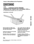
Owner's Manual/Manual
Del Propietario
CRI FTSMFIN°
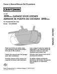
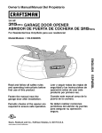
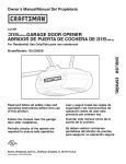
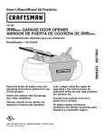
1/2 HP
GARAGE DOOR OPENER
ABRIDOR DE PUERTA DE COCHERA
For Residential
Model/Modelo
Use Only/Solo
DE
para uso residencial
139.53902D
m
Z
G3
I11
"13
Z_
O
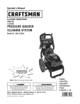
Read and follow all safety rules and
operating instructions before first use
of this product.
Fasten the manual near the garage
door after installation.
Periodic checks of the opener are
required to ensure safe operation.
0Qus
Sears, Roebuck and Co., Hoffman Estates, IL 60179 U.S.A
www.sears.com/craftsman
Leer y seguir todas las reglas de
seguridad y las instrucciones de
operacion antes de usar este producto
por primera vez.
Guardar este manual cerca de la
puerta de la cochera.
Se deben realizar revisiones
periodicas del abridor de puertas para
asegurar su operacion segura.
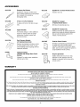
TABLE
OF CONTENTS
INTRODUCTION
2- 7
ADJUSTMENT
27-29
Safety symbol and signal word review ....................................... 2
Adjust the travel limits .............................................................. 27
Preparing your garage door ........................................................ 3
Tools needed.............................................................................. 3
Adjust the force ........................................................................ 28
Planning ..................................................................................4-5
Test the Protector System®....................................................... 29
Carton inventory ......................................................................... 6
Hardware inventory..................................................................... 7
Test the safety reversal system................................................. 29
OPERATION
30-34
Operation safety instructions .................................................... 30
ASSEMBLY
8-11
Using your garage door opener ................................................ 30
Assemble the rail ..................................................................... 8-9
Using the wall-mounted door control ....................................... 31
Fastenthe rail to the motor unit and install the trolley ............. 10
Attach the rail brackets ............................................................. 11
To open the door manually ....................................................... 31
INSTALLATION
11-26
Care of your opener.................................................................. 32
Having a problem?.................................................................... 33
Diagnostic chart ........................................................................ 34
Installation safety instructions .................................................. 11
Determine the header bracket location ..................................... 12
PROGRAMMING
Install the header bracket.......................................................... 13
To add or reprogram a hand-held remote control .................... 35
Attach the rail to the header bracket......................................... 14
Install the Protector System_............................................... 15-17
To erase all codes from motor unit memory ............................ 35
3-Function remote controls ...................................................... 35
Position the opener................................................................... 18
To add, reprogram or change a KeylessEntry PIN................... 36
Hang the opener ....................................................................... 19
Install the door control ............................................................. 20
REPAIRPARTS
Electrical requirements ............................................................. 21
Complete safety reversing sensor installation........................... 21
Install the lights ....................................................................... 22
35-36
37-38
Rail assembly parts .................................................................. 37
Installation parts ....................................................................... 37
Motor unit assembly parts ........................................................ 38
Attach the emergency release rope and handle ........................ 22
Fastenthe door bracket....................................................... 23-24
ACCESSORIES
39
Connect the door arm to the trolley ..................................... 25-26
WARRANTY
39
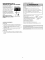
INTRODUCTION
Safely Symboland Signal WordReview
This garage door opener has been designed and tested to offer safe service provided it is installed, operated, maintained and tested in
strict accordancewith the instructions and warnings contained in this manual.
Mechanical
Electrical
When you see these Safety Symbols and Signal Words on the
following pages, they will alert you to the possibility of serious
injury or death if you do not comply with the warnings that
accompany them. The hazard may come from something
mechanical or from electric shock. Readthe warnings carefully.
When you see this Signal Word on the following pages, it will
alert you to the possibility of damageto your garage door and/or
the garage door opener if you do not comply with the cautionary
statements that accompany it. Readthem carefully.
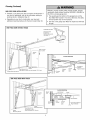
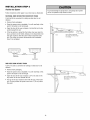
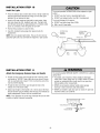
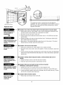
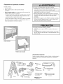
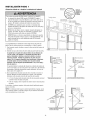
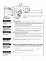
Preparing your garage door
To prevent possible SERIOUSINJURYor DEATH:
• ALWAYScall a trained door systems technician if garage
door binds, sticks, or is out of balance.An unbalanced
garage door may NOT reverse when required.
Before you begin:
• Disable locks.
• Removeany ropes connected to garage door.
• Completethe following test to make sure your garage
door is balancedand is not sticking or binding:
• NEVERtry to loosen, move or adjust garage door, door
springs, cables, pulleys, brackets or their hardware, ALL of
which are under EXTREMEtension.
1. Lift the door about halfway as shown. Releasethe door. If
balanced, it should stay in place, supported entirely by its
springs.
• DisableALL locks and remove ALL ropes connected to
garage door BEFOREinstalling and operating garage door
opener to avoid entanglement.
2. Raise and lower the door to see if there is any binding or
sticking.
If your door binds, sticks, or is out of balance, call a trained door
systems technician.
To prevent damageto garage door and opener:
• ALWAYSdisable locks BEFOREinstalling and operating the
opener.
• ONLYoperate garage door opener at 120V, 60 Hz to avoid
malfunction and damage.
SectionaJ Door
One-Piece Door
Too/s needed
During assembly, installation and adjustment of the opener,
instructions will call for hand tools as illustrated below.
Pencil
Level (Optional)
Hack Saw
Tape Measure
Wire Cutters
Drill
Stepladder
Claw Hammer
3/16", 5/16" and
5/32" Drill Bits
Screwdriver
Adjustable EndWrench
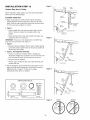
P_nnmg
Doyou have an access door in addition to the garage door? If
not, Model 53702 Emergency Key Releaseis required. See
Accessories page.
Identify the type and height of your garage door. Survey your
garage area to see if any of the conditions below apply to your
installation. Additional materials may be required. You may find it
helpful to refer back to this page and the accompanying
illustrations as you proceed with the installation of your opener.
Look at the garage door where it meets the floor. Any gap
between the floor and the bottom of the door must not exceed
1/4" (6 mm). Otherwise, the safety reversal system may not
work properly. See Adjustment Step 3. Floor or door should be
repaired.
Depending on your requirements, there are several installation
steps which may call for materials or hardware not included in
the carton.
• Installation Step 1 - Look at the wall or ceiling above the
garage door. The header bracket must be securely fastened to
structural supports.
SECTIONALDOORINSTALLATIONS
• Doyou have a steel, aluminum, fiberglass or glass panel door?
If so, horizontal and vertical reinforcement is required
(Installation Step 12).
• Installation Step 4 - Dependingupon garage construction,
extension brackets or wood blocks may be needed to install
sensors.
• The opener should be installed above the center of the door. If
there is a torsion spring or center bearing plate in the way of
the header bracket, it may be installed within 4 feet (1.2 m) to
the left or right of the door center.
See Installation Steps 1 and 12.
• Installation Step 4 - Alternate floor mounting of the safety
reversing sensor will require hardware not provided.
• Installation Step 6 - Do you have a finished ceiling in your
garage? If so, a support bracket and additional fastening
hardware may be required.
• If your door is more than 7 feet (2.13 m) high, see rail
extension kits listed on Accessories page.
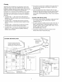
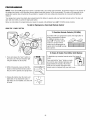
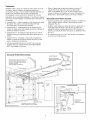
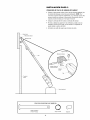
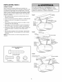
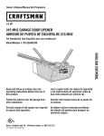
SECTIONALDOORINSTALLATION
FINISHED
CEILING
Support bracket &
fastening hardware
is required.
See page 19.
Horizontal and vertical reinforcement
is needed for lightweight garage doors
(fiberglass, steel, aluminum, door with
glass panels, etc.). See page 23 for details.
Rail
Motor unit
Header Wall
Torsion
Spring
OR
Extension
Spring
Wallmounted
Door
Control
Access Door
CLOSED
Header
Bracket
/
POSITION
Rail Assembly
......
/,,,, Hall _racKet
04--
O
Garage _o_
Door
S r,n0//
Straight /o'_/
aoor._/_o/
\Safety
Reversing Sensor
Safety Reversing
Gap between floor
Sensor
and bottom of door
must not exceed 1/4" (6 mm).
leader
Vail
arage
DOt
--
_ _
Curved
_----_[ Door
_1
D?or
Bracket Arm
--
Emergency
Release
Rope & Handle
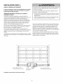
Planning(Continued)
Without a properly working safety reversal system, persons
(particularly small children) could be SERIOUSLYINJUREDor
KILLED by a closing garage door.
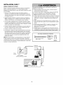
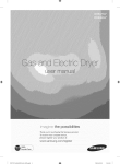
ONE-PIECEDOOR INSTALLATIONS
• Generally, a one-piece door does not require reinforcement. If
your door is lightweight, refer to the information relating to
sectional doors in Installation Step 12.
• The gap between the bottom of the garage door and the
floor MUST NOTexceed 1/4" (6 mm). Otherwise, the safety
reversal system may not work properly.
• The floor or the garage door MUST be repaired to eliminate
the gap.
• Dependingon your door's construction, you may need
additional mounting hardware for the door bracket (Step 12).
ONE-PIECEDOORWITHOUTTRACK
FINISHED
CEILING
Support bracket
& fastening
hardware is required.
See page 19.
Motor unit
Header Wall
Wall-mounted
Door Control
Rail
Bracket
CLOSED
POSITION
Rail Assembly
Emergency
Sensor
Gap between floor
and bottom of door must not exceed 1/4" (6 mm).
Safety Reversing
Sensor
_ader
all
Curved
Door
Arm
Straight
Door
Arm
Door
Rope & Handle
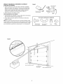
ONE-PIECEDOORWITH TRACK
CLOSED
POSITION
Bracket
Access
Trolley
Rail Assembly
Garage
Door
_
/
__aGadP
Safety
Reversing Sensor
bo_ttw_en f_oorr Reversing Sensor
'
must net exceed 1/4" (6 mm).
1
Bracket
Straight
Door
Arm
Rope & Handle
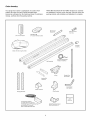
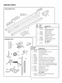
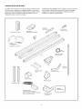
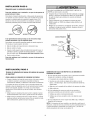
CartonInventory
Your garage door opener is packaged in one carton which
contains the motor unit and all parts illustrated below.
Accessories will depend on the model purchased. If anything is
missing, carefully check the packing material.
PARTS MAY BE STUCKIN THE FOAM.Hardware for assembly
and installation is shown on the next page. Save the carton and
packing material until installation and adjustment is complete.
Rail Support
A
Remote Control
Visor Clip
Door Control Button
SECURITY÷ ®
3-Function Remote Control
araces_
O
Sprocket
Coupling
Motor Unit with 2 Light Lenses
2-Conductor Bell Wire
White & White/Red
Rail Assembly
Trolley
Straight Door
Arm Section
Header/Rail
Brackets
Curved Door
Arm Section
Header
Hanging Brackets
Bracket
Door Bracket
Safety Labels
and
Literatu re
(1 Sending Eye and 1 Receiving Eye)
with attached 2-Conductor
White & White/Black Bell Wire
Safety Reversing Sensor
Mounting Bracket (2)
HardwareInventory
Separateall hardware and group as shown below for the assembly and installation procedures.
ASSEMBLYHARDWARE
Metal Sleeve (2)
C-Clip (2)
Hex Bolt 1/4"-20x7/16" (14)
Sprocket Coupling Sleeve
Wire Clips (6)
iNSTALLATiONHARDWARE
O
Carriage Bolt
1/4"-20xl/2" (2)
Wing Nut
1/4"-20 (2)
Ring
Fastener (3)
Handle
Nut 5/16"-18 (4)
_i i1ii] iii ,_
Hex Bolt
5/16"-18x7/8" (4)
Lag Screw
5/16"-9xl-5/8" (2)
Screw
6ABx1-1/4" (2)
Lag Screw
5/16"-18xl-7/8" (2)
Insulated
Staples (30)
Lock Washer 5/16" (4)
Screw
6-32x1" (2)
Rope
Self-Threading Screw
1/4"-14x5/8" (2)
Drywall Anchors (2)
oD
Clevis Pin
5/16"x2-3/4" (1)
Spacer
o_
Clevis Pin
5/16"xl" (1)
o_
ClevisPin
5/16"x1-1/4"(1)
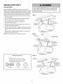
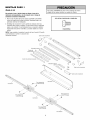
ASSEMBLY
STEP
1
Assemb/ethe Rai/
To prevent INJURY from pinching, keep hands and fingers
away from the joints while assembling the rail.
To avoid installation difficulties, do not run the garage door
opener until instructedto do so.
1. Open the rail carton and remove the contents onto a level work
surface. Keepit clean and free of debris while you are working.
HARDWARESHOWN ACTUALSIZE
2. Identify the rail sections and orient the sections on a flat
surface as shown. The back rail has a black gear on one end.
The header rail has a black plastic rack inside the rail on the
screw. The remaining section is the center rail.
Hex Bolt 1/4-20x7/16"
NOTE: Use caution when handling the center rail section. The
screw can slip out if the section is tipped up too far.
Remove Cardboard
Packing
Hanging Brackets
Rail Support Braces
Rail Assembly
Straight Door Arm
Header Rail Brackets
Rail Assembly
(_
@
_
Remove Cardboard
Sprocket
Coupling
Remove
Cardboard
Packing
Hex Bolts
Back
._/4-20x7/16"
Hex Bolts
1/4-20x7/16"
Hex Bolts
1/4-20x7/16"
Hex Bolts
1/4-20x7/16"
Header Rail
Packing
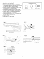
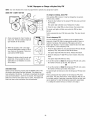
Assemb/e the Raft (continued)
HARDWARESHOWN ACTUALSIZE
3. Attach rail support braces to the back rail. Loosely insert
1/4-20x7/16" hex bolts into the aligned holes of the end rail and
rail support brace (Figure 1). Do not finger tighten.
4. Extend the drive screw a few inches from the center rail, and
slide the sleeve onto the long journal (Figure 2).
Metal Sleeve
C-Clip
Hex bolt 1/4-20x7/16"
5. Interlock the long and short journal of the center and back
rails. Slide the sleeve over the journal connection (Figure 3).
6. Placethe c-clip onto the long journal shaft (center rail) to
ensure that the sleeve does not slide (Figure 4).
7. Slide the center rail so that the center rail and rail brace holes
are aligned (Figure 5). Secure with bolts.
8. Tighten all hex bolts.
9. Repeatsteps 3-8 for header section.
Figure4
Figure1
Rail
Rail Support Brace
I
Center Rail
/
Rail Support Brace
Figure 2
\__
Figure5
.........
Drive Screw
_
Metal Sleeve
I .........
Long Journal
Rail Support Brace
Center Rail
[
Center Rail
Figure3
'
i
Short Journal
I
Metal Sleeve
i
Rail Support Brace
ig Journal
ASSEMBLY
STEP
2
HARDWARESHOWN ACTUALSIZE
Fasten the Rail to the Motor Unit and Install the
Trolley
NOTE: To aid in assembly and installation, replace the foam
packing around the motor unit. Remove it after Installation
Step 4.
Hex Bolt 1/4-20x7/16"
1. Working on a level surface, align the rail assembly with the
motor unit, as shown.
2. Slip the coupling over the rail sprocket.
3. Slide the rail through the motor unit bracket until the coupling
fits securely over the motor unit sprocket.
4. Align the four bolt holes in the rail with those in the motor unit
bracket. Insert four 1/4"-20x7/16" hex bolts. Tighten securely
with a 3/8" socket wrench.
5. Disengagetrolley by turning the releasearm down. Slide trolley
onto and along the bottom of the rail until it aligns with the
rack. Turn releasearm up. This will join the rack and the
trolley.
Motor Unit
Bracket
Motor Unit
Sprocket
Hex Bolts
1/4-20x7/16"
Coupling
\
1
Rail Sprocket
/
Hex Bolts
1/4-20x7/16"
Rail
Assembly
Foam Packaging
Release arm
Trolleyunit
10
ASSEMBLY
STEP
3
Rail Brackets
Attachthe Raft Brackets
• Align rail brackets to end of rail assembly, as shown.
• insert two 1/4"-20x7/16" hex bolts. Tighten securely with a 3/8"
socket.
Youhave now finished assembfingyour garage door opener.
Please read the following warningsbeforeproceeding to the
installation section.
Hex Bolt
1/4"-20x7/16"
Rail
Hex Bolt
1/4"-B0x7/16"
HARDWARESHOWN ACTUAL SiZE
Hex Bolt 1/4"-20x7/16"
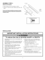
iNSTALLATiON
iMPORTANT iNSTALLATiON iNSTRUCTiONS
To reduce the risk of SEVERE iNJURY or DEATH:
1. READAND FOLLOWALL iNSTALLATiONWARNINGSAND
INSTRUCTIONS.
8. NEVERwear watches, rings or loose clothing while
installing or servicing opener. They could be caught in
garage door or opener mechanisms.
2. install garage door opener ONLY on properly balanced and
lubricated garage door. An improperly balanceddoor may
NOT reverse when required and could result in SEVERE
INJURYor DEATH.
9. Install wall-mounted garage door control:
• within sight of the garage door.
• out of reach of children at minimum height of
5' (1.5 m).
• away from ALL moving parts of the door.
3. ALL repairs to cables, spring assemblies and other
hardware MUST be made by a trained door systems
technician BEFOREinstalling opener.
10. Placeentrapment warning label on wall next to garage door
control.
4. Disable ALL locks and remove ALL ropes connected to
garage door BEFOREinstalling opener to avoid
entanglement.
11. Placemanual release/safety reversetest label in plain view
on inside of garage door.
5. installgarage door opener 7' (2.13 m) or more above floor.
12. Upon completion of installation, test safety reversal
system. Door MUST reverse on contact with a
1-1/2" (3.8 cm) high object (or a 2x4 laid flat) on the floor.
6. Mount the emergency releasewithin reach, but at least6
feet (1.8 m) abovethe floor and avoiding contact with
vehicles to avoid accidental release.
7. NEVERconnect garage door opener to power source until
instructed to do so.
11
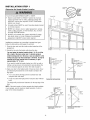
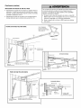
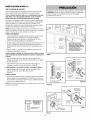
iNSTALLATiON
STEP
1
Unf!nished
Determine the HeaderBracketLocation
Ceiling _
To prevent possible SERIOUSINJURYor DEATH:
• Headerbracket MUST be RIGIDLY fastened to structural
support on header wall or ceiling, otherwise garage door
might NOT reverse when required. DO NOT install header
bracket over drywall.
BRACKETHEADERFORMOuNTCE
HeaderWall
Vertical Centerline
of Garage Door
2x4
Structural
Supports
• Concrete anchors MUST be used if mounting header bracket
or 2x4 into masonry.
• NEVERtry to loosen, move or adjust garage door, springs,
cables, pulleys, brackets, or their hardware, ALL of which
are under EXTREMEtension.
• ALWAYScall a trained door systems technician if garage
door binds, sticks, or is out of balance.An unbalanced
garage door might NOT reversewhen required.
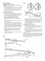
Installation procedures vary according to garage door types.
Follow the instructions which apply to your door.
1. Close the door and mark the inside vertical centefline of the
garage door.
2. Extend the line onto the header wall above the door.
You can fasten the header bracket within 4' (1.22 m) of the
left or right of the door center only if a torsionspringor
center bearing plate is in the way; or you can attach it to the
ceiling (see page 13) when clearance is minimal. (it may be
mountedon the wail upsidedown if necessary,to gain
approximately 1/2" (1 cm).)
Header Wall
Header Wall
(7.5 cm)
_====_
If you need to install the header bracket on a 2x4 (on wall or
ceiling), use lag screws (not provided) to securely fasten the
2x4 to structural supports as shown here and on page 13.
,,
/Track
Highest Point
of Travel
Y
3. Open your door to the highest point of travel as shown. Draw
an intersecting horizontal line on the header wall above the
high point:
//
Y
Highest Point
of Travel
• 3" (7.5 cm) above the high point for sectional door and
one-piece door with track.
• 8" (20 cm) abovethe high point for one-piece door without
track.
Sectional door with curvedtrack
0he-piece door with horizontaltrack
This height will provide travel clearance for the top edge of the
door.
Header Wall
NOTE:If the total number of inches exceedsthe height available
in your garage, use the maximum height possible, or refer to
page 13 for ceiling installation.
',- 8" (20 cm)
Wall
Door 2° ihest
,;-
I_
Point
Highest
Point
of Travel
Door
Pivot
_Hardware
i
of Travel
0no-piece deer without track:
jamb hardware
12
0no-piece doer without track:
pivot hardware
INSTALLATION
STEP
2
Install the Header Bracket
Wall Mounting
Holes
You can attach the header bracket either to the wall above the
garage door, or to the ceiling. Follow the instructions which will
work best for your particular requirements. Do not install the
header bracket over drywall. If installing into masonry, use
concreteanchors(not provided).
The nail hole is for
positioning only.
You must use lag screws
to mount the header bracket.
Optional
Wall Mounting Holes
WALL HEADERBRACKETINSTALLATION
* Center the bracket on the vertical centerline with the bottom
edge of the bracket on the horizontal line as shown (with the
arrow pointing toward the ceiling).
Header
• Mark the vertical set of bracket holes (do not use the holes
designated for ceiling mount). Drill 3/16" pilot holes and fasten
the bracket securely to a structural support with the hardware
provided.
_iiiiiiiSJiii_iiiiiii/iiiiiiii
2x4
Structural
Support_
HARDWARESHOWN ACTUALSIZE
d"
Horizontal
Line
_, _
j
I
J
Garage Door Travel
Highest Point of
_,_
Lag Screw
5/16"-9xl -5/8"
Garage Door
CEILINGHEADERBRACKETINSTALLATION
• Extend the vertical centerline onto the ceiling as shown.
• Center the bracket on the vertical mark, no more than
6" (15 cm) from the wall. Make sure the arrow is pointing
toward the wall. The bracket can be mounted flush against the
ceiling when clearance is minimal.
• Mark the side holes. Drill 3/16" pilot holes and fasten bracket
securely to a structural support with the hardware provided.
_
t/
_
_
Finished Ceiling
_Header
Bracket
Vertical
Centerline
: Garage Door
6" (15 cm)
Maximum
Door
S
Lag Screws
5/16"-9xl -5/8"
Ceiling Mounting Holes
Header Wall
The nail hole is for
positioning only.
You must use lag screws
to mount the header bracket.
of Garage Door
13
INSTALLATION
STEP
3
Attachthe Rail to the HeaderBracket
• Position the opener on the garage floor below the header
bracket. Use packing material as a protective base. NOTE:If the
door spring is in the way you'll need help. Have someone hold
the opener securely on a temporary support to allow the rail to
clear the spring.
• Position the header/rail bracket against the header bracket.
• Align the bracket holes and join with a clevis pin 5/16"x2-3/4"
as shown. Spacer can be installed on either side of rail.
• Insert a ring fastener to secure.
/Header
Bracket
Ring Fastener\
Header Bracket
0
Spac2
5/16"x2-3/4"
\ _ _Header/Rail
Bracket
Garage
Door
_]
\
/
Opener Carton or
Temporary
Support
HARDWARESHOWN ACTUALSIZE
°1
Clevis Pin
5/16"x2-3/4"
0
Ring Fastener
14
Spacer
iNSTALLATiON
STEP
4
Install The ProtectorSystem®
Be sure power is NOTconnected to the garage door opener
BEFOREinstalling the safety reversing sensor.
The safety reversingsensormust be connected and aligned
correctly before the garage door opener will move in the down
direction.
To prevent SERIOUSINJURY or DEATHfrom a closing garage
door:
• Correctly connect and align the safety reversing sensor. This
required safety device MUST NOT be disabled.
iMPORTANTiNFORMATiONABOUTTHE SAFETYREVERSING
SENSOR
• install the safety reversing sensor so beam is NO HIGHER
than 6" (15 cm) above garage floor.
When properly connected and aligned, the sensor will detect an
obstacle in the path of its electronic beam. The sending eye (with
an amber indicator light) transmits an invisible light beam to the
receiving eye (with a green indicator light), if an obstruction
breaks the light beam while the door is closing, the door will stop
and reverse to full open position, and the opener lights will flash
10 times.
If it is necessaryto mount the units on the wail, the brackets
must be securely fastened to a solid surface such as the wall
framing. Extension brackets (see Accessories) are availableif
needed. If installing in masonry construction, add a piece of wood
at each location to avoid drilling extra holes in masonry if
repositioning is necessary.
The units must be installed inside the garage so that the sending
and receiving eyes face each other across the door, no more than
6" (15 cm) above the floor. Either can be installed on the left or
right of the door as long as the sun never shines directly into the
receiving eye lens.
The invisible light beam path must be unobstructed. No part of
the garage door (or door tracks, springs, hinges, rollers or other
hardware) may interrupt the beam while the door is closing.
The mounting brackets are designed to clip onto the track of
sectional garage doors without additional hardware.
Facing the door from inside the garage
15
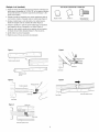
INSTALLINGTHE BRACKETS
Be sure power to the opener is disconnected. Install and align
the brackets so the sensors will face each other across the garage
door, with the beam no higher than 6" (15 cm) above the floor.
They may be installed in one of three ways, as follows.
Figure 1
DOOR TRACK MOUNT
_
(RIGHT SIDE)
Door
II Tr::
Garage doortrack installation (preferred):
* Slip the curved arms over the rounded edge of each door track,
with the curved arms facing the door. Snap into place against
the side of the track. It should lie flush, with the lip hugging the
back edge of the track, as shown in Figure 1.
Indicator
Light
_
Senso_r._
If your door track will not support the bracket securely, wall
installation is recommended.
Waft installation (Figure 2 & 3):
acket
• Placethe bracket against the wall with curved arms facing the
door. Be sure there is enough clearancefor the sensor beam to
be unobstructed.
Figure 2
WALL MOUNT (RIGHT SIDE)
* If additional depth is needed,an extension bracket (see
Accessories) or wood blocks can be used.
Fasten Wood Block to Wall with
Lag Screws (Not Provided)
Indicator
Light
Sensor
* Use bracket mounting holes as a template to locate and drill
(2) 3/16" diameter pilot holes on the wall at eachside of the
door, no higher than 6" (15 cm) above the floor.
.__
Bracket
* Attach brackets to wall with lag screws (not provided).
* If using extension brackets or wood blocks, adjust right and
left assemblies to the same distance out from the mounting
surface. Make sure all door hardware obstructions are cleared.
7L b
-7
|-
(Not Provided)
Lens
--_
Floor installation (Figure 4):
* Use wood blocks or extension brackets (see Accessories) to
elevate sensor brackets so the lenses will be no higher than
6" (15 cm) abovethe floor.
Figure 3
WALL MOUNT (RIGHT SIDE)
• Carefully measure and place right and left assemblies at the
same distance out from the wall. Be sure all door hardware
obstructions are cleared.
iiiiiiiiiiiiiiii!ili!
Bracket
iiiiiiiii;ii (See Accessories)
ii!iliiiiiiiiiiiiiiiiii!i:i/
J_
(Providedwith
!i!!it
iiiiiiiii:iiiiii/ -
• Fastento the floor with concrete anchors as shown.
ExtensionBracket)
(Provigd
Extension
Bracket)
with
._._-"
Lens
Figure 4
FLOOR
Light
MOUNT (RIGHT SIDE)
HARDWARESHOWN ACTUALSIZE
--
ttach with
Concrete Anchors
(Not Provided)
Carriage Bolt
1/4"-20x 1/2"
Wing Nut
1/4"-20
Staples
Light
Bracket
J
16
MOUNTINGANDWIRING THE SAFETYSENSORS
Figure 5
• Slide a 1/4"-20xl/2" carriage bolt head into the slot on each
sensor. Use wing nuts to fasten sensors to brackets, with
lenses pointing toward each other across the door. Be sure the
lens is not obstructed by a bracket extension (Figure 5).
Wing Nut
1/4"-20
• Finger tighten the wing nuts.
RecommendedWire Routing
Lens
1. Using insulated staples, run the wires from both sensors to the
rail at the door header (Figure 6).
2. Run the wires through wire clip at the top of the rails.
HARDWARESHOWN ACTUALSIZE
NOTE:If your access door is near the garage door, you may
choose to instafl the door control at this time and run the door
control wire along the raft with the sensor wires. If you choose
this option, follow instructions 1-3 on page 20.
Carriage Bolt
1/4"-20x 1/2"
Wing Nut
1/4 "-20
Figure 6
Sensor Wire
Wire Clip
Bell Wire
Safety Reversing
Sensor
Invisible Light Beam
Protection Area
Safety Reversing
Sensor
17
Staples
Wire Clip
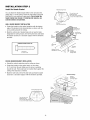
INSTALLATION
STEP
5
Positionthe Opener
To prevent damageto garage door, rest garage door opener
rail on 2x4 placed on top section of door.
Follow instructions which apply to your door type as illustrated.
SECTIONALDOOROR ONE-PIECEDOORWITH TRACK
A 2x4 laid flat is convenient for setting an ideal door-to-rail
distance.
• Removefoam packaging.
• Raisethe opener onto a stepladder. You will need help at this
point if the ladder is not tall enough.
• Open the door all the way and place a 2x4 laid flat on the top
section beneath the rail.
oor
_:::: _:__
• If the top section or panel hits the trolley when you raise the
door, pull down on the trolley releasearm to disconnect inner
and outer sections. Slide the outer trolley toward the motor
unit. The trolley can remain disconnected until Installation
Step 13 is completed.
J
--
Trolley
Release Arm
--
ENGAGED
RELEASED
ONE-PIECEDOORWITHOUTTRACK
A 2x4 on its side is convenient for setting an ideal door-to-rail
distance.
• Removefoam packaging.
• Raisethe opener onto a stepladder. You will need help at this
point if the ladder is not tall enough.
• Open the door all the way and place a 2x4 on its side on the
top section of the door beneath the rail.
• The top of the door should be level with the top of the motor
unit. Do not position the opener more than 4" (10 cm) above
this point.
18
____
iI
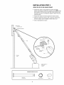
INSTALLATION
STEP
6
Hang the Opener
To avoid possible SERIOUSINJURYfrom a falling garage door
opener, fasten it SECURELYto structural supports of the
garage. Concrete anchors MUST be used if installing ANY
brackets into masonry.
Three representative installations are shown. Yours may be
different. Hanging brackets should be angled (Figure 1) to provide
rigid support. On finished ceilings (Figure 2 and Figure 3), attach
a sturdy metal bracket to structural supports before installing the
opener. This bracket and fastening hardware are not provided.
1. Measure the distance from each side of the motor unit to the
structural support.
Figure 1
Supports
2. Cut both pieces of the hanging bracket to required lengths.
3. Drill 3/16" pilot holes in the structural supports.
Measure
Distance
4. Attach one end of each bracket to a support with
5/16"-18xl -7/8" lag screws.
',
\
Lag Screws
5/16"-18xl -7/8"
Bolt 5/16"- 18x7/8"
Lock
Nut 5/16"-18
5. Fastenthe opener to the hanging brackets with 5/16"-18x7/8"
hex bolts, lock washers and nuts.
6. Checkto make sure the rail is centered over the door (or in line
with the header bracket if the bracket is not centered above the
door).
7. Removethe 2x4. Operatethe door manually. If the door hits
the rail, raise the header bracket.
NOTE:DO NOT connect power to opener at this time.
Figure 2
Hidden
Support
....
-
_ _- FINISHED
.-_
_-
CEILING
Lag Screws
5/16"-18xl-7/8"
(Not Provided)
Bolt 5/16"-18x7/8"
Lock Washer 5/16"
Nut 5/16"-18
Bolt 5/16"- 18x7/8"
Lock Washer 5/16"_
Nut 5/16"-18
Figure 3
HARDWARESHOWN ACTUALSIZE
Lag Screws
5/16"-18xl -7/8"
D,,,,,,,,,,D
@
Hex Bolt
5/16"-18x7/8"
Nut 5/16"- 18
Bolt 5/16"-18x7/8"
Lock Washer 5/16'
Nut 5/16"-18
Lock Washer 5/16"
19
(Not Provided)
Bolt 5/16"-18x7/8"
Lock Washer 5/16"
Nut 5/16"-18
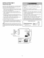
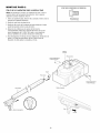
INSTALLATION
STEP
7
Install the Door Control
To prevent possible SERIOUSINJURYor DEATHfrom
electrocution:
Locate door control within sight of door, at a minimum height of
5 feet (1.5 m) where small children cannot reach, away from
moving parts of door and door hardware.
* Be sure power is NOT connected BEFOREinstalling door
control.
1. Strip 1/4" (6 mm) of insulation from one end of bell wire and
connect to the two terminal screws on back of door control by
color: white to 2 and white/red to 1.
* Connect ONLYto 24 VOLTlow voltage wires.
To prevent possible SERIOUSINJURYor DEATHfrom a closing
garage door:
2. Fastenthe Door Control Button securely with 6ABx1-1/2"
screws. If installing into drywall, drill 5/32" holes and use the
anchors provided.
* Install door control within sight of garage door, out of reach
of children at a minimum height of 5 feet (1.5 m), and away
from ALL moving parts of door.
3. Run bell wire up wall and across ceiling to motor unit. Use
insulated staples to secure wire in several places. Do not pierce
wire with a staple, creating a short or open circuit.
* NEVERpermit children to operate or play with door control
push buttons or remote control transmitters.
. Activate door ONLYwhen it can be seen clearly, is properly
adjusted, and there are no obstructions to door travel.
4. Connect the bell wire to the quick-connect terminals on the
motor unit panel: white to white; white/red to red.
5. Position the antennawire as shown.
. ALWAYS keepgarage door in sight until completely closed.
NEVERpermit anyone to cross path of closing garage door.
6. Usetacks or staples to permanently attach entrapment warning
label to wall near door control, and manual release/safety
reverse test label in a prominent location on inside of garage
door.
HARDWARESHOWN ACTUALSIZE
NOTE:DO NOT connect power and operate opener at this time.
Thetrolley will travel to the furl open position but will not return to
the close position until the sensor beam is connected and properly
aligned.
Screw 6ABx1-1/2"
Lighted Door Control Button
Quick-Connect
Terminals
Terre lna'
(BACK VIEW)
DOOR CONTROL
BUTTON
To release or insert wire,
push in tab with
screwdriver tip
Strip wire 7/16"
(11 mm)
7/16"
Door Control
Connections
Red_
(11 mm)l
Antenna
White
20
Grey
Drywall Anchors
Insulated
Staples
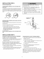
iNSTALLATiON
STEP
8
Electrical Requirements
To prevent possible SERIOUSINJURYor DEATHfrom
electrocution or fire:
To avoid installation difficulties, do not run the opener until
Step 9 below.
• Be sure power is NOTconnected to the opener, and
disconnect power to circuit BEFOREremoving cover to
establish permanent wiring connection.
• Garage door installation and wiring MUST be in compliance
with ALL local electrical and building codes.
• NEVERuse an extension cord, 2-wire adapter, or change
plug in ANY way to make it fit outlet. Be sure the opener is
grounded.
To reduce the risk of electric shock, your garage door opener has
a grounding type plug with a third grounding pin. This plug will
only fit into a grounding type outlet. If the plug doesn't fit into the
outlet you have, contact a qualified electrician to install the proper
outlet.
PERMANENT WIRING
CONNECTION
if permanent wiring is required by your JocaJcode, refer to the
foJJowing procedure.
Ground Tab
Green
Ground Screw
To make a permanent connection through the 7/8" hole in the top
of the motor unit:
• Remove the motor unit cover screws and set the cover aside.
Black
Wire
Ground Wire
• Remove the attached 3-prong cord.
• Connect the black (line) wire to the screw on the brass
terminal; the white (neutral) wire to the screw on the silver
terminal; and the ground wire to the green ground screw.
The opener must be grounded.
= Reinstall the cover.
White Wire
Black Wire
To avoid installation difficulties, do not run the opener at this
time.
iNSTALLATiON
STEP
9
Complete the Safety Reversing Sensor Installation
TROUBLESHOOTING
THE SAFETYREVERSINGSENSORS
ALiGNiNG THE SAFETYREVERSINGSENSORS
1. If the sending eyeindicator light does not glow steadily after
installation,check for:
• Plug in the opener. The indicatorlightsin both the sending and
receiving eyeswill glow steadily if wiring connections and
alignment are correct.
• Electric power to the opener.
• A short in the white or white/black wires. These can occur at
staples, or at opener connections.
The sending eye amber indicator light will glow regardless of
alignment or obstruction. If the green indicatorlight in the
receiving eye is off, dim, or flickering (and the invisible light beam
path is not obstructed), alignment is required:
= incorrect wiring between sensors and opener.
= A broken wire.
2. If the sending eyeindicator light glows steadily but the
receiving eye indicatorlightdoesn't:
• Loosen the sending eyewing nut and readjust, aiming directly
at the receiving eye. Lock in place.
= Check alignment.
• Loosen the receiving eye wing nut and adjust the sensor until it
receives the sender's beam. When the green indicatorlight
glows steadily, tighten the wing nut.
= Checkfor an open wire to the receiving eye.
3. if the receiving eye indicatorlight is dim, realign either sensor.
NOTE: When the invisible beam path is obstructed or misaligned
while the door is closing, the door will reverse. If the door is
already open, it will not close. The opener lights will flash 10
times (see page 15).
21
INSTALLATION
STEP
10
Install the Lights
To prevent possible OVERHEATINGof the endpanel or light
socket:
• Press the releasetabs on both sides of lens. Gently rotate lens
back and downward until the lens hinge is in the fully open
position. Do not remove the lens.
• DONOT use short neck or specialty light bulbs.
• DONOT use halogen bulbs. Use ONLY incandescent.
To prevent damageto the opener:
• Install a 100 watt maximum light bulb in each socket. Light
bulb size should be A19, standard neck only. The lights will
turn ON and remain lit for approximately 4-1/2 minutes when
power is connected. Then the lights will turn OFF.
• DONOT use bulbs larger than IOOW.
• ONLY use A19 size bulbs.
• Reversethe procedure to close the lens.
• Use A19, standard neck garage door opener bulbs for
replacement.
100 Watt (Max)
_R
100 Watt (Max)
Standard
Light Bulb
NOTE: Use only standard light bulbs. The use of short neck or
speciafity light bulbs may overheat the endpanel or light socket.
\,
Light Bulb
elease Tab
Standard
Release Tab
,/
_
'_Lens
Hinge
INSTALLATION
STEP
11
To prevent possible SERIOUSINJURYor DEATHfrom a falling
garage door:
• If possible, use emergency releasehandle to disengage
trolley ONLYwhen garage door is CLOSED.Weak or broken
springs or unbalanceddoor could result in an open door
falling rapidly and/or unexpectedly.
• NEVERuse emergency releasehandle unless garage
doorway is clear of persons and obstructions.
• NEVERuse handle to pull door open or closed. If rope knot
becomes untied, you could fall.
Attachthe EmergencyRelease Ropeand Handle
• Thread one end of the rope through the hole in the top of the
red handle so "NOTICE"reads right side up as shown. Secure
with an overhand knot at least 1" (2.5 cm) from the end of the
rope to prevent slipping.
• Thread the other end of the rope through the hole in the
releasearm of the outer trolley.
• Adjust rope length so the handle is 6' (1.83 m) abovethe floor.
Ensure that the rope and handle clear the tops of all vehicles to
avoid entanglement. Secure with an overhand knot.
NOTE:If it is necessary to cut the rope, heat seal the cut end with
a match or lighter to prevent unraveling.
rolley
Trolley Releai_i_en_
Release Handle
22
Ov_erhand
_jKnot
iNSTALLATiON
STEP
12
Fastenthe Boor Bracket
Fiberglass, aluminum or lightweight steel garage doors WILL
REQUIREreinforcement BEFOREinstallation of door bracket.
Contact your door manufacturer for reinforcement kit.
Follow instructions which apply to your door type as illustrated
below or on the following page.
A horizontal reinforcementbrace should be IonSenough to be
securedto two or three vertical supports.A vertical
reinforcementbrace should cover the height of the top panel
Figure 1 shows one piece of angle iron as the horizontal brace.
For the vertical brace, 2 pieces of angle iron are used to create a
U-shaped support. The best solution is to check with your garage
door manufacturer for an opener installation door reinforcement
kit.
Door
Bracket
Location
NOTE:Many door reinforcement kits provide for direct
attachment of the clevis pin and door arm. In this case you will
not need the door bracket, proceed to Step 12.
_ HORIZONTAL
SECTIONALDOORS
AND VERTICAL
IS NEEDED
FOR LIGHTWEIGHT
GARAGE
DOORS (FIBERGLASS,
ALUMINUM,
STEEL, DOORS
WITH GLASS PANEL, ETC.).
(NOT PROVIDED)
Vertical
Centerline
of Garage
Door
1. Center the door bracket on the previously marked vertical
centerline used for the header bracket installation. Note correct
UP placement, as stamped inside the bracket.
2. Position the top edge of the bracket 2"-4" (5-10 cm) below the
top edge of the door, OR directly below any structural support
across the top of the door.
Figure 1
3. Mark, drift holes and install as follows, depending on your
door's construction:
(Not Provided
Vertical
Metal or light weight doorsusing a verticalangle iron brace
between the door panel support and the doorbracket:
L%
iJ°H
Vertical Centerline
. .0eooo
_f,_
1,o,0 _ Ve rtic°_rlc_:trline
* Drill 3/16" fastening holes. Secure the door bracket using the
two 1/4"-14x5/8" self-threading screws. (Figure 2A)
* Alternately, use two 5/16" bolts, lock washers and nuts (not
provided). (Figure 2B)
]}arage
_o
Door
Lock Washer
Metal, insulated or light weight factory reinforced doors:
* Drill 3/16" fastening holes. Secure the door bracket using the
self-threading screws (Figure 3).
Wood Doors:
S e If-T h readi n g --------=-_
Screw 1/4"-14x5/8"
Nut 5/16"-18
Figure 2B
* Use top and bottom or side to side door bracket holes. Drill
5/16" holes through the door and secure bracket with 5/16"x2"
carriage bolts, lock washers and nuts (not provided). (Figure 4)
Figure 2A
Bolt 5/16"x2"
(Not Provided
NOTE: The 1/4"-14x5/8" self-threading screws are not intended for
use on wood doors.
_
'.4
Centerline
:
HARDWARESHOWN
Figure 3
ACTUAL SiZE
23
Board
Vertical
Centerline
of Garage
Door
of[_
DoGrarage
q "¢_ Se,f-Threadio
elf-Threading
crew
/4"- 14x5/8"
inside Edge
of Door or
Reinforcement
,_Vertical
_
_ll_J
__.
5/16'_.
Door Bracket _j/"__Up
"'_
Screw
l
1/4"- 14x5/8"
/
Figure 4
0NE-PIECEDOORS
Please read and comply with the warnings and reinforcement
instructions on the previous page. They apply to one-piece doors
also.
• Center the door bracket on the top of the door, in line with the
header bracket as shown. Mark either the left and right, or the
top and bottom holes.
HARDWARESHOWN
ACTUALSIZE
• Metal Doors: Drill 3/16" pilot holes and fasten the bracket with
the 1/4"-14x5/8" self-threading screws provided.
• WoodDoors: Drill 5/16" holes and use 5/16"x2" carriage bolts,
lock washers and nuts (not provided) or 5/16"x1-1/2" lag
screws (not provided) depending on your installation needs.
Self-Threading
1/4"-14x5/8"
NOTE: Thedoor bracket may be installed on the top edge of the
door if required for your installation. (Refer to the dotted line
optional placement drawing.)
Screw
__
;
Door
Header Wall
2x4 Support
--
Finished Ceiling --
'
Bracket
elf-Threading
Screw
1/4"- 14x5/8"
Top of Door
(Inside
Garage)
of Door
Placement
Door
Bracket
METAL DOOR
Optional
Placement
of Door
Bracket
Vertical
Centerline
Garage
HORIZONTAL AND VERTICAL
REINFORCEMENT
IS NEEDED
FOR LIGHTWEIGHT
GARAGE
DOORS (FIBERGLASS,
ALUMINUM, STEEL, DOORS
WITH GLASS PANEL, ETC.).
NOT PROVIDED)
Nut
5/16"-18 _
,_
Washer
Lock
5/16"
Top of Door
(Inside
Garage)
of
Top Edge
of Door
Optional
Placement
'
_
For a door with no exposed framing,
or for the optional installation, use
lag screws 5/16"x1-1/2" (Not Provided)
to fasten door bracket.
24
Carriage
_
Bolt
(Not Provided)
5/16"x2"
WOOD DOOR
INSTALLATION
STEP
13
Figure 1
Inner
Trolley
ConnectBoor Arm to Trolley
Outer
Trolley
Follow instructions which apply to your door type as illustrated
below and on the following page.
Ring
Fastener
SECTIONALDOORSONLY
• Make sure garage door is fully closed. Pull the emergency
releasehandle to disconnect the outer trolley from the inner
trolley. Slide the outer trolley back (away from the door) about
2" (5 cm) as shown in Figures 1, 2 and 3.
Clevis Pin
5/16"xl"
Straight
o
Release
Handle
Door
Bracket
• Figure1:
- Fastenstraight door arm section to outer trolley with the
5/16"x1" clevis pin. Secure the connection with a ring
fastener.
Curved Door Arm
Clevis Pin
5/16"x1-1/4"
- Fastencurved section to the door bracket in the same way,
using the 5/16"x1-1/4" clevis pin.
Figure 2
IMPORTANT: Thegroove on the straight door arm MUST face
away from the curved door arm (Figure 4).
• Figure 2:
- Bring arm sections together. Find two pairs of holes that line
up and join sections. Select holes as far apart as possible to
increase door arm rigidity.
Washers/o/
II
I
II
5/16" /o/
• Figure 3, Hole alignment alternative:
Nuts
II
/O/
- If holes in curved arm are above holes in straight arm,
disconnect straight arm. Cut about 6" (15 cm) from the solid
end. Reconnectto trolley with cut end down as shown.
- Bring arm sections together.
L)_-.-,.._-'_'-_
_
t Bolts
r\---J
- Find two pairs of holes that line up and join with bolts, lock
washers and nuts.
j
• Pull the emergency release handle toward the opener at a 45°
angle so that the trolley release arm is horizontal. Proceedto
Adjustment Step 1, page 27. Trolley will re-engage
automatically when opener is operated.
5/16,,-18x7/8,,
"Door Bracket
Figure 3
Lock
Washers
5/16"
HARDWARESHOWN ACTUALSIZE
Nuts
5/16"-18
p
Nut 5/16"-18
Lock Washer 5/16"
Ring Fastener
Bolts
5/16"-18x7/8"
°i
Clevis Pin
5/16"xl" (Trolley)
Clevis Pin
5/16"x1-1/4"
(Door Bracket)
Cut this end
Hex Bolt
5/16"-18x7/8"
Figure 4
25
CORRECT
iNCORRECT
ALL ONE-PIECEDOORS
CORRECT
Figure 5
iNCORRECT
1. Assembte the door arm, Figure 5:
NIPORTANT:Thegroove on the straight door arm MUST face
away from the curved door arm.
= Fastenthe straight and curved door arm sections together to
the longest possible length (with a 2 or 3 hole overlap).
= With the door closed, connect the straight door arm section
to the door bracket with the 5/16"x1-1/4" clevis pin.
Door
= Secure with a ring fastener.
Bracket
Fastener
2. Adjustmentprocedures, Figure 6:
Lock
Washers
5/16"
• On one-piece doors, before connecting the door arm to the
trolley, the travel limits must be adjusted. Limit adjustment
screws are located on the left side panel as shown on
page 27. Follow adjustment procedures below.
Clevis Pin
5/16"x1-1/4"
- Turn the UP limit adjustment screw counter-clockwise 4
turns.
- Manually raise the door to the open position (parallel to the
floor), and lift the door arm to the trolley. The arm should
touch the trolley just in back of the door arm connector
hole. Refer to the fully open trolley/door arm positions in the
illustration. If the arm does not extend far enough, adjust
the limit further. One full turn equals 2" (5 cm) of trolley
travel.
3. Connect the door arm to the trolley:
• Close the door and join the curved arm to the connector hole
in the trolley with the remaining clevis pin. It may be
necessary to lift the door slightly to make the connection.
= Secure with a ring fastener.
• Closed door adjustment: decrease DOWNtravel limit
= Run the opener through a complete travel cycle, if the door
has a slight "backward" slant in full open position as shown
in the illustration, decrease the UP limit until the door is
parallel to the floor.
- Turn the DOWNlimit adjustment screw clockwise 4
complete turns.
- Press the Door Control push button. The trolley will travel to
the fully closed position.
NOTE: When setting the up limit on the foflowing page, the door
should not have a "backward" slant when fully open as illustrated
below. A slight backward slant will cause unnecessarybucking
and/or jerking operation as the door is being opened or closed
from the fully open position.
Figure 6
Outer Trolley
Closed
__
_
Door Arm ------_[,_Li
I
___
Door
_ ___
%
Curved
Door Arm
- Manually close the door and lift the door arm to the trolley.
The arm should touch the trolley just ahead of the door arm
connector hole. Refer to the fully closed trolley/door arm
positions in the illustration. If the arm is behind the
connector hole, adjust the limit further. Onefull turn equals
2" (5 cm) of trolley travel.
- Press the Door Control push button. The trolley will travel to
the fully open position.
lley
Straight
Arm
Bolts
5/16"-18x7/8
• Open door adjustment: decrease UP travel limit
Nuts
5/16"-18
Emergency
Release Handle
Closed
Door
Inner Trolley
Backward
(incorrect)
Open Door
26
Slant
ADJUSTMENT
STEP
1
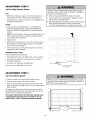
Adjustthe TravelLimits
Without a properly installed safety reversal system, persons
(particularly small children) could be SERIOUSLYINJUREDor
KILLED by a closing garage door.
• Incorrect adjustment of garage door travel limits will
interfere with proper operation of safety reversal system.
• If one control (force or travel limits) is adjusted, the other
control may also need adjustment.
• After ANY adjustments are made, the safety reversal system
MUST be tested. Door MUST reverse on contact with
1-1/2" (3.8 cm) high object (or 2x4 laid flat) on floor.
Limit adjustment settings regulatethe points at which the door
will stop when moving up or down.
To operate the opener, press the Door Control push bar. Run the
opener through a complete travel cycle.
• Does the door open and close completely?
• Does the door stay closed and not reverse unintentionally when
fully closed?
If your door passes both of these tests, no limit adjustments are
necessary unless the reversing test fails (Adjustment Step 3,
page 29).
Adjustment procedures are outlined below. Readthe procedures
carefully before proceeding to Adjustment Step 2. Use a
screwdriver to make limit adjustments. Runthe opener througha
completetravel cycleafter each adjustment.
NOTE:Repeated operation of the opener during adjustment
procedures may cause the motor to overheat and shut off. Simply
wait 15 minutes and try again. If anything interferes with the
door's upward travel, it will stop. If anything interferes with the
door's downward travel (including binding or unbalanced doors),
it will reverse.
To prevent damageto vehicles, be sure fully open door
provides adequateclearance.
HOW AND WHENTO ADJUSTTHE LIMITS
• If the door does not open completelybut opensat least
5 feet (1.5 m):
Increase up travel. Turn the UP limit adjustment screw
clockwise. Oneturn equals 2" (5 cm) of travel.
0
• If door does not openat least 5 feet (1.5 m):
Adjust the UP (open) force as explained in Adjustment Step 2.
.........
• If the door does not close completely:
Increase down travel. Turn the down limit adjustment screw
counterclockwise. Oneturn equals 2" (5 cm) of travel.
If door still won't close completely try lengthening the door
arm (page 25) and decreasing the down limit.
Limit Adjustment
Screws
Left Side Panel
• If the opener reverses in fully closedposition:
Decreasedown travel. Turn the down limit adjustment screw
clockwise. Oneturn equals 2" (5 cm) of travel.
• If the door reverses when closingand there is no visible
interferenceto travel cycle:
If the opener lights are flashing, the Safety Reversing Sensors
are either not installed, misaligned, or obstructed. See
Troubleshooting, page 21.
ADJUSTMENT
Test the door for binding: Pull the emergency releasehandle.
Manually open and close the door. If the door is binding or
unbalanced, call for a trained door systems technician. If the
door is balanced and not binding, adjust the DOWN(close)
force. See Adjustment Step 2.
27
LABEL
ADJUSTMENT
STEP
2
Adjustthe Force
Without a properly installed safety reversal system, persons
(particularly small children) could be SERIOUSLYINJUREDor
KILLED by a closing garage door.
• Too much force on garage door will interfere with proper
operation of safety reversal system.
• NEVERincrease force beyond minimum amount required to
close garage door.
• NEVERuse force adjustments to compensate for a binding
or sticking garage door.
• If one control (force or travel limits) is adjusted, the other
control may also need adjustment.
• After ANY adjustments are made, the safety reversal system
MUST be tested. Door MUST reverse on contact with
1-1/2" (3.8 cm) high object (or 2x4 laid flat) on floor.
Force adjustment controls are located on the back panel of the
motor unit. Force adjustment settings regulate the amount of
power required to open and close the door.
If the forces are set too light, door travel may be interrupted by
nuisance reversals in the down direction and stops in the up
direction. Weather conditions can affect the door movement, so
occasional adjustment may be needed.
The maximum force adjustment range is about3/4 of a
completeturn. Do not force controls beyond that point. Turn
force adjustment controls with a screwdriver.
NOTE:If anything interferes with the door's upward travel, it will
stop. If anything interferes with the door's downward travel
(including binding or unbalanced doors), it will reverse.
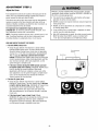
HOW AND WHENTO ADJUSTTHE FORCES
1. Testthe DOWN(c/ose) force
• Grasp the door bottom when the door is about halfway
through DOWN(close) travel. The door should reverse.
Reversal halfway through down travel does not guarantee
reversal on a 1-1/2" (3.8 cm) obstruction. See Adjustment
Step 3, page 29. If the door is hard to hold or doesn't
reverse, DECREASEthe DOWN(close) force by turning the
control counterclockwise. Make small adjustments until the
door reverses normally. After each adjustment, run the
opener through a complete cycle.
Force Adjustment
Controls
Back Panel
• If the door reverses duringthe DOWN (close) cycleand
the opener lights aren't flashing, INCREASEDOWN (close)
force by turning the control clockwise. Make small
adjustments until the door completes a close cycle. After
each adjustment, run the opener through a complete travel
cycle. Do not increase the force beyond the minimum
amount required to close the door.
j
2. Testthe UP (open) force
ADJUSTMENT
• Grasp the door bottom when the door is about halfway
through UP (open) travel. The door should stop. If the door
is hard to hold or doesn'tstop, DECREASEUP (open) force
by turning the control counterclockwise. Make small
adjustments until the door stops easily and opens fully.
After each adjustment, run the opener through a complete
travel cycle.
Open Force
• If the door doesn't openat least 5 feet (1.5 m),
INCREASEUP (open) force by turning the control clockwise.
Make small adjustments until door opens completely.
Re-adjust the UP limit if necessary. After each adjustment,
run the opener through a complete travel cycle.
28
LABEL
Close Force
ADJUSTMENT
STEP
3
Testthe SafetyReversal System
Without a properly installed safety reversal system, persons
(particularly small children) could be SERIOUSLYINJUREDor
KILLED by a closing garage door.
• Safety reversal system MUST be tested every month.
TEST
• With the door fully open, place a 1-1/2" (3.8 cm) board (or a
2x4 laid flat) on the floor, centered under the garage door.
• If one control (force or travel limits) is adjusted, the other
control may also need adjustment.
• After ANY adjustments are made, the safety reversal system
MUST be tested. Door MUST reverse on contact with
1-1/2" (3.8 cm) high object (or 2x4 laid flat) on the floor.
• Operatethe door in the down direction. The door must reverse
on striking the obstruction.
ADJUST
• If the door stops on the obstruction, it is not traveling far
enough in the down direction. Increasethe DOWNlimit by
turning the DOWNlimit adjustment screw counterclockwise
1/4 turn.
NOTE:On a sectional door, make sure limit adjustments do not
force the door arm beyond a straight up and down position.
See the illustration on page 25.
• Repeatthe test.
• When the door reverses on the 1-1/2" (3.8 cm) board, remove
the obstruction and run the opener through 3 or 4 complete
travel cycles to test adjustment.
• If the unit continues to fail the Safety ReverseTest, call for a
trained door systems technician.
IMPORTANTSAFETYCHECK:
Test the Safety ReverseSystem after:
• Each adjustment of door arm length, limits, or force controls.
• Any repair to or adjustment of the garage door (including
springs and hardware).
• Any repair to or buckling of the garage floor.
• Any repair to or adjustment of the opener.
(or a 2x4 laid flat)
ADJUSTMENT
STEP
4
Test The ProtectorSysterr_
• Press the remote control push button to open the door.
Without a properly installed safety reversing sensor, persons
(particularly small children) could be SERIOUSLYINJUREDor
KILLED by a closing garage door.
• Placethe opener carton in the path of the door.
• Press the remote control push button to close the door. The
door will not move more than an inch (2.5 cm), and the opener
lights will flash.
The garage door opener will not close from a remote control if
the indicator light in either sensor is off (alerting you to the fact
that the sensor is misaligned or obstructed).
If the opener closesthe door when the safety reversingsensor
is obstructed(and the sensorsare no more than 6" (15 cm)
above the floor), call for a trained door systemstechnician.
Safety Reversing
29
Sensor
Safety Reversing Sensor
OPERATION
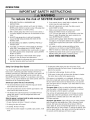
iMPORTANT SAFETY iNSTRUCTiONS
To reduce the risk of SEVERE INJURY or DEATH:
1. READAND FOLLOWALL WARNINGSAND
INSTRUCTIONS.
9. If one control (force or travel limits) is adjusted, the other
control may also need adjustment.
2. ALWAYS keep remote controls out of reach of children.
NEVERpermit children to operate or play with garage door
control push buttons or remote controls.
3. ONLY activate garage door when it can be seen clearly, it
is properly adjusted, and there are no obstructions to door
travel.
10. After ANY adjustments are made, the safety reversal
system MUST be tested.
11. Safety reversal system MUST be tested every month.
Garagedoor MUST reverse on contact with
1-1/2" (3.8 cm) high object (or a 2x4 laid fiat) on the floor.
Failure to adjust the garage door opener properly may
cause SEVEREINJURYor DEATH.
4. ALWAYS keep garage door in sight until completely
closed. NO ONESHOULDCROSSTHE PATH OFTHE
MOVING DOOR.
5. NO ONESHOULDGO UNDERA STOPPED,PARTIALLY
OPENEDDOOR.
12. ALWAYS KEEPGARAGEDOORPROPERLYBALANCED
(see page 3). An improperly balanceddoor may NOT
reverse when required and could result in SEVEREINJURY
or DEATH.
6. If possible, use emergency releasehandle to disengage
trolley ONLYwhen garage door is CLOSED.Weak or
broken springs or unbalanceddoor could result in an open
door failing rapidly and/or unexpectedly, causing SEVERE
INJURYor DEATH.
13. ALL repairs to cables, spring assemblies and other
hardware, ALL of which are under EXTREMEtension,
MUST be made by a trained door systems technician.
14. ALWAYSdisconnect electric power to garage door opener
BEFOREmaking ANY repairs or removing covers.
7. NEVERuse emergency releasehandle unless garage
doorway is clear of persons and obstructions.
15 SAVETHESEINSTRUCTIONS.
8. NEVERuse handle to pull garage door open or closed. If
rope knot becomes untied, you could fall.
Using YourGarageDoor Opener
Your Security+ _eopener and hand-held remote control have been
factory-set to a matching code which changes with each use,
randomly accessing over 100 billion new codes. Your opener will
operate with up to eight Security÷ _eremote controls and one
Security÷ ® KeylessEntry System. If you purchase a new remote
control, or if you wish to deactivate any remote control, follow the
instructions in the Programming section.
Activateyour opener with any of the following:
• The hand-held Remote Control: Hold the large push button
down until the door starts to move.
• The waft-mounted Door Control: Hold the push button or bar
down until the door starts to move.
• The KeylessEntry (See Accessories): If provided with your
garage door opener, it must be programmed before use.
See Programming.
When the opener is activated (with the safety reversingsensor
correctly installed and aligned)
1. if open, the door will close, if closed, it will open.
2. if closing, the door will reverse.
3. If opening, the door will stop.
4. If the door has been stopped in a partially open position, it will
close.
5. If obstructed while closing, the door will reverse, if the
obstruction interrupts the sensor beam, the opener lights will
blink for five seconds.
6. If obstructed while opening, the door will stop.
7. If fully open, the door will not close when the beam is broken.
The sensor has no effect in the opening cycle.
If the sensor is not installed, or is misaiigned, the door won't
close from a hand-held remote control. However, you can close
the door with the Door Control or Keyless Entry, if you activate
them until down travel is complete. If you releasethem too soon,
the door will reverse.
The opener lights will turn on under the following conditions:
when the opener is initially plugged in; when power is restored
after interruption; when the opener is activated.
They wiii turn off automatically after 4-1/2 minutes or provide
constant light when the Light feature on the Premium Control
Console Panel is activated. Bulb size is A19. Bulb power is
100 watts maximum.
Security.I"° light feature: Lights will also turn on when someone
walks through the open garage door. With a Premium Control
Console,this feature may be turned off as follows: With the
opener lights off, press and hold the light button for 10 seconds,
until the light goes on, then off again. To restore this feature, start
with the opener lights on, then press and hold the light button for
10 seconds until the light goes off, then on again.
3O
Using the Wall-Mounted Door Control
To Openthe Door Manually
Press the push button to open or close the door.
Press again to reverse the door during the
closing cycle or to stop the door while it's
opening.
To prevent possible SERIOUSINJURYor DEATHfrom a falling
garage door:
* If possible, use emergency release handle to disengage
trolley ONLY when garage door is CLOSED.Weak or broken
springs or unbalanced door could result in an open door
falling rapidly and/or unexpectedly.
* NEVERuse emergency releasehandle unless garage
doorway is clear of persons and obstructions.
* NEVERuse handle to pull door open or closed. If rope knot
becomes untied, you could fall.
DISCONNECTTHE TROLLEY:
The door should be fully closed
if possible. Pull down on the
emergency releasehandle (so
that the trolley releasearm snaps _IR
into a vertical position) and lift
the door manually.
Trolley
elease
Manual
The lockout feature prevents the
trolley from reconnecting
scornect
automatically, and the door can
Lockoutposition
be raised and lowered manually
(Manual disconnect)
as often as necessary.
Position)
TO RE-CONNECTTHE TROLLEY:
Pull the emergency release
handle toward the opener at an
angle so that the trolley release
arm is horizontal. The trolley will
reconnect on the next UP or
DOWNoperation, either manually
or by using the door control or
remote control.
Trolley
l" @ _Trolley
Release
"_;_,.._ Arm
Emergency_
Release
(Pull
at 45 °Handle
angle)
TOreconnect
31
_11
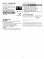
CARE
OF YOUR
OPENER
THE REMOTECONTROLCONTROLBATTERY
LIMIT AND FORCEADJUSTMENTS:
Weather conditions may cause some minor
changes in door operation requiring some
re-adjustments, particularly during the first
year of operation.
FORCECONTROLS
To prevent possible SERIOUSINJURY or DEATH:
° NEVERallow small children near batteries.
° If battery is swallowed, immediately notify doctor.
To reduce risk of fire, explosion or chemical burn:
* ReplaceONLY with 3V2032 coin batteries.
Pages 27 and 28 refer to the limit and
force adjustments. Only a screwdriver is
required. Follow the instructions carefully.
° DO NOT recharge, disassemble, heat above 100°C (212°F)
or incinerate.
Repeat the safety reverse test (Adjustment
Step 3, page 29) after any adjustmentof
limits or force.
The lithium battery should produce
power for up to 5 years. To replace
ADJUSTMENT LABEL
Open thisend
first to avoid_
battery, use the visor clip or screwdriver cracking
_
blade to pry open the case as shown,
hous_
Insert battery positive side up (+).
MAINTENANCESCHEDULE
Dispose of old battery properly.
Oncea Month
Replace the battery with only 3V2032
coin cell batteries.
• Manually operate door. If it is unbalancedor binding, call a
trained door systems technician.
_
,_
_zj
NOTICE:To comply with FCCand or Industry Canadarules (IC),adjustment or modifications of this
receiver and/or transmitter are prohibited, except for changing the code setting or replacing the
battery.THEREARE NOOTHERUSERSERVICEABLEPARTS.
Tested to Comply with FCCStandards FOR HOMEOR OFFICEUSE. Operation is subject to the
following two conditions: (1) this device may not cause harmful interference, and (2) this device
must acceptany interference received,including interferencethat may cause undesiredoperation.
° Checkto be sure door opens & closes fully. Adjust limits and/
or force if necessary (see pages 27 and 28).
° Repeatthe safety reversetest. Make any necessary
adjustments (see Adjustment Step 3).
Oncea Year
• Oil door rollers, bearings and hinges. The opener does not
require additional lubrication. Do not greasethe door tracks.
32
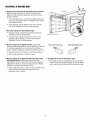
HAVING
A PROBLEM?
1. My door will not close and the light bulbs blink on my motor
unit: The safety reversing sensor must be connected and
aligned correctly before the garage door opener will move in
the down direction.
Bell Wire
/
* Verify the safety sensors are properly installed, aligned and
free of any obstructions. Refer to Installation Step 4: Install
TheProtector System° .
• Check diagnostic LED for flashes on the motor unit then
refer to the Diagnostic Chart on the following page.
2. My remote controlswill not activate the door:
• Reprogram remote controls following the programming
instructions. Refer to Programming.
Safety Reversing Sensor
• If remote control will still not activate your door, check
diagnostic LEDfor flashes on motor unit then refer to
Diagnostic Chart on the following page.
3. My door reversesfor no apparent reason: Repeat safety
reversetest after adjustments to force or travel limits. The need
for occasional adjustment for the force and limit settings is
normal. Weather conditions in particular can affect door travel.
Sending Eye Safety Reversing
Sensor (Amber Indicator Light)
Receiving Eye Safety Reversing
Sensor (Green Indicator Light)
• Manually check door for balance or any binding problems.
• Refer to Adjustment Step 2, Adjust the force.
4. My door reversesfor no apparent reason after fully closing
and touchingthe floor: Repeatsafety reverse test after
adjustments to force or travel limits,The need for occasional
adjustment for the force and limitsettings is normal. Weather
conditions in particular can affect door travel.
5. My lights will not turn off when door is open:
• The garage door opener is equipped with a security light
feature, This feature activates the light on when the safety
sensor beam has been obstructed. See Accessories page.
• Refer to Adjustment Step 1, Adjust the UPand DOWN Travel
Limits. Decreasedown travel by turning down limit
adjustment screw clockwise.
33
Bell Wire
r I.,£_I.,£_Z,£_,L'_,£.,L'_,£.,£_I.,£_,L'_
Z,L'_I.,£_Z_
7777777777777777777_
Your garage door opener is programmed with self-diagnostic
capabilities. The "Learn" button/diagnostic LED will flash a number of
times then pause signifying it has found a potential issue. Consult
Diagnostic Chart below.
Safety Reversing Sensor
Diagnostic Chart
'-0
Symptom:One or both of the Indicator fightson the safety sensorsdo not g/ow steady.
• Inspect sensor wires for a short (staple in wire), correct wiring polarity (black/white wires
reversed), broken or disconnected wires, replace/attach as needed.
• Disconnect all wires from back of motor unit.
Safety reversingsensors
wire open (broken or
disconnected).
OR
• Removesensors from brackets and shorten sensor wires to 1-2 ft (30-60 cm) from back
each of sensor.
• Reattachsending eye to motor unit using shortened wires. If sending eye indicator light
glows steadily, attach the receiving eye.
Safety reversingsensorswire
shorted or black/whitewire
reversed.
• Align sensors, if the indicator lights glow replacethe wires for the sensors. If the sensor
indicator lights do not light, replacethe safety sensors.
"0
Symptom:LED is not lit on doorcontrol.
• Inspect door control/wires for a short (staple in wire), replaceas needed.
Door controlor wire
shorted.
• Disconnectwires at door control, touch wires together. If motor unit activates, replace door
control.
• If motor unit does not activate, disconnect door control wires from motor unit. Momentarily
short across red and white terminals with jumper wire. If motor unit activates, replace door
control wires.
-0
Safety reversingsensors
slightly misaligned (dim or
flashing LED).
Symptom:Sendingindicator fight g/ows steadily, receiving indicator/ight is dim or
flashing.
• Realign receiving eye sensor, clean lens and secure brackets.
• Verify door track is firmly secured to wall and does not move.
"0
Motor overheated or possible
RPM sensorfailure. Unplug
to reset.
Symptom:Motor has over heated; the motor unit doesnot operate;
RPM Sensor= Short trave/ 6-8" (15-20 cm).
* Unplug unit to reset. Try to operate motor unit, check diagnostic code.
. If it is still flashing 5 times and motor unit moves 6-8" (15-20 cm), replace RPM sensor.
* If motor unit doesn't operate, motor unit is overheated.Wait 30 minutes and retry. If motor
unit still will not operate replacelogic board.
'-0
Motor Circuit Failure.
Replace Receiver
Logic Board.
Symptom:Motor unit doesn't operate.
• Replacelogic board because motor rarely fails.
34
PROGRAMMING
NOTICE:If this Security,!,_garage door opener is operated with a non-rolling code transmitter, the technical measure in the receiver of
the garage door opener, which provides security against code-theft devices, will be circumvented. Theowner of the copyright in the
garage door opener does not authorize the purchaser or supplier of the non-rolling code transmitter to circumvent that technical
measure.
Your garage door opener has already been programmed at the factory to operatewith your hand-held remote control. The door will
open and close when you press the large push button.
Below are instructions for programming your opener to operate with additional Security÷ ° 315 MHz remote controls.
To Add or Reprograma Hand-heldRemote Control
USINGTHE "LEARN" BUTTON
*3-Function Remote Controls (315 MHz)
If provided with your garage door opener, the large button is
factory programmed to operate
it. Additional buttons on any
Security÷ _ 3-Function remote
control or compact remote
control can be programmed to
operate other Security÷ _ garage
door openers.
To Erase All Codes From Motor Unit Memory
To deactivate any unwanted remote control, first erase all
1. Press and releasethe "learn" button on
the motor unit. The learn indicator light
will glow steadily for 30 seconds.
Press and hold the "learn" button on motor
unit until the learn indicator light goes out
(approximately 6 seconds). All previous
codes are now erased. Reprogram each
remote control or keyless entry you wish to use.
2. Within 30 seconds, press and hold the
button on the hand-held remote control*
that you wish to operateyour garage door.
3. Releasethe button when the motor unit
lights blink. It has learned the code. If
light bulbs are not installed, two clicks will
be heard.
\1/
35
To Add, Reprogram or Change a Key/ess Entry PIN
NOTE: Your new KeylessEntry must be programmed to operateyour garage door opener.
USINGTHE "LEARN" BUTTON
Tochange an existing,known PIN
If the existing PIN is known, it may be changed by one person
without using a ladder.
1. Press the four buttons for the present PIN, then press and hold
the # button.
_. ',,
The opener light will blink twice. Releasethe # button.
2. Press the new 4-digit PIN you have chosen, then press Enter.
The motor unit lights will blink once when the PIN has been
learned.
Test by pressing the new PIN, then press Enter. The door should
move.
Toset a temporary PIN
1. Press and releasethe "learn" button on
motor unit. The learn indicator light will
glow steadily for 30 seconds.
You may authorize access by visitors or service people with a
temporary 4-digit PIN. After a programmed number of hours or
number of accesses, this temporary PIN expires and will no
longer open the door. It can be used to close the door even after
it has expired. To set a temporary PIN:
2. Within 30 seconds, enter a four digit
personal identification number (PIN) of
your choice on the keypad. Then press
and hold the ENTERbutton.
3. Releasethe button when the motor unit
lights blink. It has learned the code. If
light bulbs are not installed, two clicks
will be heard.
1. Press the four buttons for your personal entry PIN (not the last
temporary PIN), then press and hold the _, button.
The opener light will blink three times. Releasethe button.
2. Press the temporary 4-digit PIN you have chosen, then press
Enter.
\1
/
The opener light will blink four times.
3. To set the number of hoursthis temporary PIN will work, press
the number of hours (up to 255), then press _,.
OR
3. To set the number of timesthis temporary PIN will work, press
the number of times (up to 255), then press #.
One ButtonC/ose:
Opener can be closed by pressing only the ENTERbutton if the
one button close feature has been activated. This feature has
been activated at the factory. To activate or deactivate this feature
press and hold buttons 1 and 9 for 10 seconds. The keypad will
blink twice when the one button close is active. The keypad will
blink four times when one button close is deactivated.
The opener light will blink once when the temporary PIN has been
learned.
Test by pressing the four buttons for the temporary PIN, then
press Enter. The door should move. If the temporary PIN was set
to a certain number of openings, remember that the test has used
up one opening. To clear the temporary password, repeat steps
1-3, setting the number of hours or times to 0 in step 3.
36
REPAIR
PARTS
Raft Assemb/yParts
KEY PART
NO. NO.
1
81 C275
5
4
3
2
41A6263
3
4
12B890
5
6
7
8
/nsta//ationParts
DESCRiPTiON
Rack
Hardware bag (includes
sprocket coupling)
Left rail bracket
12B900
41A6264
Right rail bracket
Screw drive rail assembly
Complete7' (2.1 m)
12B889
41A6262
Rail support brace
Completetrolley assembly
41A4836
Drive sprocket kit
NOTSHOWN
28A143
Wire Clips
m
KEY PART
NO. NO.
5
10=
13
11
9
DESCRIPTION
1 41A4166
Door control button
2
41A6140
3-Function remote control case
(no circuit board)
3
10A20
3V 2032 Lithium battery
4
29B137
Visor clip
5
41A2828
6
Emergency releaserope & handle assy.
41B4494-1 2-Conductor bell wire: white & white/red
7
41A4353
Headerbracket w/clevis pin &fastener
8
41A5047
Door bracket w/clevis pin & fastener
9
41A5034
Safety sensor kit: receiving and sending eyes
with 3' (.9 m) 2-conductor bell wire attached
10 178B34
Straight door arm section
11 12B776
Hanging bracket
Curved door arm section
12 178B35
13 41A5266-1 Safety sensor bracket
io
NOTSHOWN
41A4675-14 installation hardware bag (see page 7)
114A4072 Owner's manual
.J
37
Motor Unit Assembly Parts
13
14
12
6
(Down)
Contact
Brown
LIMIT SWITCH
ASSY.
Wire
I_IF
' _
Dr,ve :j"
14
Gear
Gre"_
....
_/__
Center Limit
Contact
(Up)
Contact
L_J
Yellow
Wire
11
KEY
NO.
PART
NO.
DESCRIPTION
KEY
NO.
1
31C568
Drive shaft cover
2
41 B4245
Line cord
3
30B620
4
41A3150
5
41 D4671
Limit switch assembly
6
41A6241
11
6a
20B21-1
Motor drive assembly
Drive belt
High voltage wire harness
41AS150R-2M Receiver logic board
assembly
41A5594-4
Cover
12
41C22-1
Drive coupling hub
7
41C4672
Screw drive RPIVIkit
13
175B88
Light socket
14
108D77
Light lens
Capacitor- 1/2
Terminal block w/screws
PART
NO.
DESCRIPTION
8
41A4837-1
Worm gear and retainer
9
41A6635
Low voltage wire harness
9a
41A6634
10
38
ACCESSORIES
139.53702
EmergencyKey Release:
139.53753
Requiredfor a garage with NOaccess
door. Enableshomeowner to open garage
door manually from outside by
disengaging trolley.
139.53405
Includes visor clip.
8 Foot(2.4 m) Rail Extension:
o
139.53752
fully.
To allow an 8 foot (2.4 m) door to open
139.53589
139.53754
SECURITY+® KeylessEntry:
Enableshomeowner to operategarage door
opener from outside by entering a password.
Also can add a temporary password for
visitors or service persons.
139.53687
Premium ControlConsole:
For finished ceilings or where additional
support is required, based on garage
construction. Includes brackets and
fastening hardware.
Door Clearance Brackets:
(For SectionalDoors Only)
Provides a lock feature to prevent operation
of garage door from portable remote
controls. A light feature controls the opener
lights. Can be used to program the opener to
accept additional remote controls.
Replacestop brackets and rollers on door
to reduce height of door travel. For use
when installing opener in garage with low
headroom clearance.
41A5281
SECURITY+®Compact
3-FunctionRemote Control:
With loop for attaching key ring.
SupportBrackets:
139.53709
SECURITY+®3-Function Remote Control:
ExtensionBrackets:
Plug-In Light Control:
Service)
(Optional) For safety sensor installation
onto the wall or floor.
(Available onlythrough Sears Parts &
139.5374_
Enables homeowner to turn on a lamp,
television or other appliance from car,
bedside, or anywhere in the home with a
remote control.
WARRANTY
CRAFTSMAN
GARAGE DOOR OPENER LIMITED WARRANTY
90-DAY IN-HOME FULL WARRANTY ON PRODUCT
For 90 days from the date of purchase, this product will be repaired, free of charge, if defective in material or workmanship.
ADDITIONAL LIMITED WARRANTY ON PARTS
From the 91st day up to 3 year from the date of purchase, replacement parts for any defective parts on this product will be furnished, free of charge. You pay for labor.
ADDITIONAL LIFETIME LIMITED WARRANTY ON MOTOR
From the 91st day and through 7 years, if the motor on this product is defective, a replacement motor will be furnished free of charge. You pay for labor.
WARRANTY RESTRICTION
This Craftsman Garage Door Opener Limited Warranty does not cover light bulbs or repair parts necessary because of operator abuse or negligence, including the failure to install, adjust
and operate this garage door opener according to instructions contained in the owner's manual. This limiled warranty also does nel cover any problems caused by interference.
LIMITATION ON LIABILITY
Seller will not be liable for loss or damage to property or any incidental or consequential loss or expense from property damage due directly or indirectly to the use of this product.
Some states do not allow the exclusion or limitation of incidental or consequential damages, so the above limitation or exclusion may not apply to you.
DISCLAIMER OF IMPLIED WARRANTIES
Except for the motor, all implied warranties for this product, including but not limited to any implied warranties of merchantability and fitness for a particular purpose, are limited
in duration to the 91st day through3-year limited warranty period set forth above. All implied warranties with respect to the motor are limited in duration to the 91st day through
7-year limited warranty period set forth above. No implied warranties will exist or apply after such periods. Some States do not allow limitations on how long an implied warranty
lasts, so the above limitations may not apply to you.
FROM THE 91ST DAY, WARRANTY SERVICE IS AVAILABLEBY SIMPLY CONTACTINGTHE NEAREST SEARS STORE OR SEARS SERVICECENTERIN THE UNITED STATES.
WARRANTY SERVICE IS AVAILABLEBY CALLING 1-800-4-MY-HOME _;.
This warranty applies only while this product is in use in the United States.
This warranty gives you specific legal rights, and you may also have other rights which vary from state to state.
Sears, Roebuck and Co., Dept. 817WA, Hefhnan Estates, IL 60179
39
CONTENIDO
INTRODUCCI#N
2-7
AJUSTES
27-29
Revisi6n de los simbolos y t6rminos de seguridad ................................ 2
Ajuste el limite del recorrido ................................................................. 27
Preparaci6n de la puerta de su cochera.................................................. 3
Ajuste la fuerza ..................................................................................... 28
Herramientas necesarias......................................................................... 3
Pruebe el sistema de retroceso de seguridad .......................................29
Pruebe la Sistema de Protecci6n_;........................................................ 29
Planificaci6n ...................................................................................... 4-5
Inventariode la caja de cart6n................................................................ 6
Inventariode piezas................................................................................ 7
OPERACI#N
30-34
Instrucci6nes importantes de seguridad ...............................................30
MONTAJE
8-11
C6mo usar su abridor de puerta de cochera......................................... 30
Monte el riel........................................................................................ 8-9
C6mo usar la unidad de control de la puerta........................................ 31
Fije el riel a la unidad del motor y instale el trole ................................. 10
C6mo abrir la puerta manualmente ...................................................... 31
Fijaci6n de las m6nsulas del riel ........................................................... 11
INSTALACI#N
11-26
Mantenimiento de su abridor de puerta de cochera .............................32
Si tiene alg_n problema........................................................................ 33
Tabla de diagn6stico ............................................................................. 34
Instrucci6nes importantes para la instalaci6n....................................... 11
Determine d6nde va a instalar la M6nsula del Cabezal......................... 12
PROGRAMACI#N
Instale la m6nsula del cabezal............................................................... 13
Como agregar o reprogramar un control remoto manual.....................35
0olocaci6n del riel en la m6nsula del cabezal....................................... 14
Instale La Sistema de Protecci6n_;.................................................. 15-17
Para borrar todos los c6digos de la memoria de la
unidad del motor .................................................................................. 35
Coloque el abridor en posici6n ............................................................. 18
Controles remotos de 3 funciones ........................................................ 35
Cuelgue el abridor ................................................................................. 19
C6mo agregar, reprogramar o cambiar un c6digo
de entrada sin Ilave............................................................................... 36
Instale la unidad de control de la puerta............................................... 20
Requisitos para la instalaci6n el6ctrica................................................. 21
Termine la instalaci6n del sensor del sistema reversa
de seguridad......................................................................................... 21
35-36
ACCESORIOS
37
GARANTiA
37
Instale las luces .................................................................................... 22
Coloque la cuerda y la manija de emergencia....................................... 22
NtlMEROSDE SERVICIO
CONTRA
TAPA
Fije la m6nsula de la puerta ............................................................ 23-24
Conecte el brazo de la puerta al trole .............................................. 25-26
INTRODUCCION
Revisi6n de los Simbolosy T_rminosde Seguridad
Este abridor de puerta de cochera ha sido diseSadoy probado para un funcionamiento seguro, siempre y cuando se instale, se pruebe, se opere y se
le d6 mantenimiento como se indica en este manual, cumpliendo al pie de la letra con todas las advertencias e instrucciones generales aqui
contenidas.
Mecanica
EI6ctrica
Estas advertencias y/o simbolos de seguridad que aparecen en este
manual le alertar_.nde que existe el riesgo de una lesi#n seria o de
muerte si no se siguen las instrucciones correspondientes. El peligro
puede ser el6ctrico (electrocuci6n) o mec_.nico.Lea las instrucciones con
mucho cuidado.
Ouandovea esta palabra y/o simbolo de seguridad en este manual, le
alertar_,de que existe el riesgo de daSar la puerta de la cocheray/o el
abridor si no se siguen las instrucciones correspondientes. Lea las
instrucciones con mucho cuidado.
Preparaci#nde la puerta de su cochera
Antes de comenzar:
Para evitar una LESIONGRAVEo INCLUSOLA MUERTE:
• Quite los seguros.
•
Retire cualquier cuerda o cable que est_ conectado
a la puerta.
•
Haga la siguiente prueba con su puerta para verificar que est_ balanceaday que no se atore ni se pandee:
,, SlEMPRE Ilame a un t_cnico profesional para que le d_ servicio a
su puerta de cochera si _sta se atora, se pandea o est,,
desbalanceada.Una puerta de cochera que no est_ bien balanceada
puede que NO retroceda como se requiere.
,, NUNCAintente afiojar, mover ni ajustar la puerta de su cochera,
los resortes de la puerta, los cables, las poleas, las m_nsulas ni la
tornilleda, pues TODOSestos elementos est_,nbajo tensi6n
EXTREMA.
1. Levante la puerta hasta la mitad de su recorrido como se muestra.
Suelte la puerta. Si est6.baianceada,deber_,mantenerse en esa
posici6n con s61oei soporte de los resortes.
,, Quite TODOSlosseguros y retire TODASlas cuerdas conectadas a
la puerta de cochera ANTES de instalar y operar el abridor de la
puerta de cochera para evitar que se enreden.
2. Suba y baje la puerta; observe si se atora con algo o si se pandea.
Si su puerta se atora o se pandea, o no est,. balanceadaIlamea un
t_cnico especializado en sistemas de puertas.
Para evitar que se da_en el puerta y el abridor:
,, SIEMPRE quite losseguros ANTESde instalar y/o de operar el
abridor.
Z
,, SOLAMENTEopere el abridor de puerta de cochera con corriente
de 120V, 60Hz con objeto de evitar su mal funcionamiento y que el
abridor se dare.
Z
Puertaseccional
Puerta de una sola pieza
Herramientasnecesafias
Durante el montaje, instalaci6n y ajuste del abridor, las instrucciones le
indicar6,nc6mo usar las herramientas que aparecenen la siguiente
ilustraci6n.
L_piz
Sierra de mano
Cinta de medir
Cortadora de alambre
Taladro
Martillo
Brocas de 3/16, 5/16
y 5/32 de pulgada
Llave inglesa
Escalera
0
0
1/_v_S3/Se
_ Ue
e;_ga da
Destornillador
Planificaci6n
Observeel punto donde la puerta hace contacto con el piso. El
espacio entre la basede la puerta y el piso no debe exceder
6 mm (1/4 de pulgada). Si no es asi, se corre el riesgo de que el
sistema de retroceso de emergencia no funcione correctamente. Vea
Ajustes, Paso3. Ser_.necesario reparar ya sea el piso o la puerta.
Identifique la altura y el tipo de su puerta de cochera. Reviseel Areade
su cochera y observe si alguna de las siguientes instalaciones
corresponden a la suya. A veces se requieren materiales adicionales, asi
que tal vez sea conveniente tener esta hoja y las ilustraciones
correspondientes a mano cuando inicie la instalaci6n de su abridor.
Dependiendo de sus necesidades individuales, es posible queen algunos
casos vaya a necesitar materiales o herramientas que no se incluyen con
este producto.
•
Instalaci6n Paso 1 - Observe la pared o el cielo raso justo por encima
de la puerta de la cochera. La m_nsula del cabezaldebe estar
firmemente sujeta a los soportes de la estructura.
•
Instalaci6n Paso 4 - Dependiendo del tipo de construcci6n de su
cochera, es posible que necesite m_nsulas de extensi6n o bloques de
madera para instalar los sensores.
•
Instalaci6n Paso 4 - El montaje en el piso del sensor que activa el
sistema de retroceso de seguridad podria requerir piezas que no se
incluyen.
•
INSTALACIONCON UNA PUERTASECCIONAL
• Si tiene una puerta de acero, aluminio, fibra de vidrio o con paneles de
vidrio, necesitar_,refuerzos verticales y horizontales en la puerta.
(Instalaci6n, Paso 12.)
• El abridor se debe instalar por encima del centro de la puerta, pero si
existe alg0n resorte de tensi6n o placa de apoyo en el paso de la
m_nsula del cabezal, se puede instalar hasta a 1.22 m (4 pies) a la
derecha o a la izquierda del centro de la puerta. Vea Instalaci6n, Pasos
del 1 a112.
• Si su puerta es de m_.sde 2.13 m (7 pies) de altura, vea Extensiones
de riel en la secci6n de Accesorios.
Instalaci6n Paso 6 - Si el plaf6n o cielo raso de su cochera tiene
acabado, es posible que necesite una m_nsula de soporte y/o m_.s
pernos y tornilleria para la instalaci6n.
• &Hayotra puerta que d_ acceso a la cochera? Si no es asi, ser_.
necesario contar con el sistema de Ilave de emergencia Modelo
53702. Vea la p_.ginade Accesorios.
INSTALACION
ENUNAPUERTA
SECCIONAL
TECHOTERMINADO
Es necesario mensulade
soportey accesoriosde fijaci6n.
Wase la pagina 19.
Parapuertas livianasde garaje (de fibrade vidrio,
acero fino, aluminio, puertas con panelesde
vidrio, etc.), es necesario instalar un refuerzo
horizontaly uno vertical.
Wanse mas detalles en la pagina23.
Riel
Paredde cabecera
Unidad del motor
O
/
Resorte de
Resortede torsion
Control de puerta
montado en pared
Puertade
acceso
EN POSICION CERRADA
Lfnea vertical del
centro de la
..................._
.................
Mensula
del cabezal
©
,//,
Fi//A__
Riel
Mensuladel riel
I'_ Cuerday manija
la puerta recto
seguridad de reversa
La separaci6n entre el pisoy la puerta
no debe ser mayorde 6 mm (1/4 de pulg.)
3etectorde seguridad de reversa
,,beraci0n
de
emer0encia
Pared
delantera
}_
_----.__J\
_
"Brazo
. , k_ll Mensula
curvode
Puer!a_l de la
la puerta
dela
cochera
_'
puerta
'
Planificaci6n(contin#a)
INSTALACIONCON PUERTASDE UNA SOLAPIEZA
Sin un sistema de retroceso de seguridad que funcione debidamente,
al cerrar la puerta de la cochera se corre el riesgo de que las
personas (yen particular los ni_os peque_os) sufran LESIONES
GRAVESo INCLUSOLA MUERTE.
• Generalmente una puerta de una sola pieza no requiere refuerzos
adicionales. Si usted tiene una puerta de material liviano y quiere
reforzarla, consulte la informaci6n respecto a puertas seccionales,
contenida en Instalaci6n, Paso 12.
• El espacio entre la basede la puerta de la cochera y el piso NO
DEBEexceder 6 mm (1/4 de pulgada). De no ser asi, el sistema de
retroceso de seguridad no va a funcionar debidamente.
• Dependiendo del dise_o de su puerta, tal vez necesite piezas de
montaje adicionales para la m6nsula de la puerta (Paso 12).
• El piso o la puerta de la cochera se DEBE reparar para eliminar
este espacio.
PUERTA
"E
U"A
SOLA
P[EZ_
S["
OARR[L
TECHOTERM|NADO
Esnec esarb mensLla de
%__
soportey accesoriosde fijaci6n.
"_\
_/_/ -
Wase la_
Pared de cabecera
____1
d:_
_
_,
/_
m( 'cr
_
_
_---Control
acces° O
de puerta
m°ntadoenpared
_
EN POSIClON CERRADA
Riel
t_
I
____
_
Mensuladel riel
La separaci6n entre el piso y lapuerta
Sensorde
nodebe ser mayorde 6 mm (1/4 de pulg).
seguridadde reversa
Brazocurvo
del sistema de
liberaci6n
de emergencia
dell
PUERTADE UNA PIEZACONCARRIL
EN POSIClONCERRADA
Mensuladel riel
Trole
Riel
de la
cochera
_ftI
Sensor de seguridad
de reversa
seguridad de reversa
La separaci6nentre el piso y la puerta
nodebe ser mayorde 6 mm (1/4 de pulg.)
de la
puerta
Brazo de
la puerta recto
Cuerday manija
del sistema de
liberaci6nde emergencia
Inventario de/as caja de cart6n
Su abridor viene empacado en una caja de cart6n que contiene el motor
y las piezas que se muestran en la siguiente ilustraci6n. Tome nota de
que los accesorios depender_.ndel modelo que hayacomprado. Si falta
alguna pieza, revise con cuidado el material de empaque ya que en
ocasiones las piezas se atoran en el mismo.
DESTRUYAEL HULEESPUMA. Toda la tornilleria y las piezas necesarias
para el montaje e instalaci6n de su puerta se ilustran en la siguiente
p_.gina.Conserve la caja y los materiales de empaque hasta que la
instalaci6n y el ajuste se hayanterminado.
Puntales del
Brochede visera
paracontrol remoto
Bot6n de control de la puerta
Control remoto
SECURITY÷®de tres funciones
soporte
d>
Acolpe
Unidad de motor con dos micas
Cable de 2 conductores
blanco y blanco/rojo
Riel
d>
©
0
©
0
Brazo recto
de la puerta
©
0
0
Mensulasdel eabezal
y del riel
Brazo curvode la puerta
0
0
0
Mensuladel eabezal
q_
Mensulade la puerta
Mensulaspara colgar
The Protector System®
(2) Sensores de reversade seguridad
(1 emisory 1 receptor) concable de 2 eonduetores
(blancoy blaneo/negro)coneetado.
Etiquetasde
seguridady manual
Mensulaspara sensor
de seguridad (2)
Inventario de Piezas
Antes de la instalaci6n, organice todas las piezas en grupos como se muestra en la siguiente ilustraci6n.
TORNILLERiA
Y PIEZASPARAELIVIONTAJE
Manguitode metal(2)
Presillaen C (2)
Perno hexagonalde
1/4-20x7/16de pulg, (14)
Acolpe
Presillade cables (6)
TORNILLERiA
Y PIEZASPARALA INSTALACION
O
Perno de coche
de 1/4-20xl/2 pulg. (2)
de 5/16-9xl-5/8
Tuerca de mariposa
1/4-20 pulg. (2)
de pulg. (2)
@
Anillo sujetador (3)
Tuerca de
5/16-18 pulg. (4)
Pemo hexagonal
de 5/16-18x7/8 pulg. (4)
Manija
Arandela de 5/16 pulg. (4)
Grapa con
aislamiento (30)
I ITFllllll
_T_or_nillo
de cabeza cuadrada
de 5/16-18xl-7/8
pulg. (2)
Tornillo 6ABx1-1/4 pulg. (2)
Tornillo de 6-32xl pulg. (2)
dP
Taquete para muro falso (2)
Espaciador
de 1/4-14x5/8 de pulg. (2)
ol
Pasador de chaveta
de 5/16x1-1/2 pulg. (1)
Pasador de chaveta
de 5/16xl pulg. (1)
Pasador de chaveta
de 5/16x1-1/4 pulg. (1)
Cuerda
MONTAJE
PASO
1
Monte e/rie/
Para evitar LASTIMARSEal armar el riel, mantenga las manos
alejadas de las uniones mientras se acoplan los tramos.
No encienda ni use el abridor hasta que Ilegue al paso de la
instalaci6n correspondiente,de otra manera corre el riesgo de
complicar el proceso de instalaci6n.
ESTAS PIEZAS SE MUESTRANEN SU TAMA_IO REAL
1. Abra la caja de cart6n del carril y saque el contenido coloc_.ndolo
sobre una superficie de trabajo horizontal. Mantenga limpia y sin
particulas mientras est_ trabajando.
2. Identifique las secciones de carril y oriente las mismas sobre una
superficie plana seg_n se muestra. El carril trasero tiene un engranaje
negro en un extremo. El carril delantero tiene un soporte de pl_.stico
negro dentro del carril en el tornillo. La secci6n restante es el carril
central.
Perno hexagonal de
1/4-20x7/16 de pulg.
NOTA: Tengacuidado al manipular la secciSn del carril central. El tomillo
puede deslizarse y salirse si la secciSn est#
demasiado inclinada.
Quite el cart6nde protecci6n
Mensulasde soporte
Puntales del
soportedel riel
Secci6n recta del brazo de la puerta
Mensulasdel cabezal
y del riel,
(_
Quite el cart6nde protecci6n
Acolpe
_
Perno hexagonalde
Quite el cart6nde protecci6n
Caja del riel
Carril trasero
... _U4-20x7/16
de pulg.
Perno hexagonalde
Perno hexagonalde
1/4-20x7/16de pulg.
,_------_1/4-20x7/16
Carril central
Perno hexagonalde
1/4-20x7/16de pulg.
Carril delantero
de pulg.
Montaje e/tie/(contin#a)
ESTAS PIEZASSE [VIUESTRANEN SU TA[VIA_IOREAL
3. Sujete los tirones de soporte del carril al carril trasero. Introduzca sin
apretar pernos hexagonalesde 1/4-20x7/16" en los agujeros alineados
del carril de extremo y el tirante de soporte del carril (Figura 1). No
apriete con los dedos.
4. Extienda el tornillo de impulsi6n unos cuantos centimetros desde el
carril central, y deslice el manguito sobre el mu56n largo (Figura 2).
Manguitode metal
Presillaen C
Perno hexagonalde
1/4-20x7/16de pulg,
5. Enclave el mu56n largo y corto del centro y los carriles traseros.
Deslice el manguito sobre la conexi6n del mu56n (Figura 3).
6. Ooloque la presilla en 0 sobre el eje del mu56n largo (carril central)
para asegurarse de que el manguito no se deslice (Figura 4).
7. Deslice el carril central de modo que los agujeros del carril central y
del tirante del carril est_n alineados (Figura 5). Fije con pernos.
8. Apriete todos los pernos hexagonales.
9. Repita los pasos 3-8 para la secci6n de encabezado.
Figura1
Figura4
Riel
Manguitode metal
Tirante de soporte del carril
:/o
/:
i!/:
Presillaen C
I
Carril central
/
Tirantede soporte
del carril
Figura2
Figura5
Manguito de metal
/
/
Tornillo de impulsi6n
Mu56n largo
]
Carril central
Figura 3
Mu56n corto
l
Mufi6n largo
I
Tirante de soporte del carril
Carril central
Tirante de soporte del carril
MONTAJE
PASO
2
ESTASPIEZAS SE [VIUESTRANEN SU TA[VIA_IOREAL
Fije el riel a la unidadde/motor e instale el trole
NOTA:Para facilitarle el montaje y la instalaci6n del motor, vuelva a
colocarlo dentro del hule espuma de protecci6n, retire la espuma
despu#s de concluir Instalaci6n, Paso4.
1. Sobre una superficie plana, alinee el riel ya armado al motor como se
muestra en la siguiente ilustraci6n.
Pernohexagonalde
1/4-20x7/16de pulg.
2. Deslice el cople sobre la polea del riel.
3. Deslice el riel a trav6s de la m_nsula del motor hasta que el cople
quede bien ajustado sobre la polea del motor.
4. Alinee los dos orificios para los pernos del riel con los
correspondientes orificios de la m_nsula del motor. Fije con los
pernos hexagonalesde 1/4-20x7/16 de pulg. y sus respectivas
tuercas. Apri6telos con una Ilave de tuercas de 3/8 de pulg.
5. Para desengancharel trole baja el brazo de liberaci6n. Deslice el trole
dentro y a Io largo de parte inferior del riel. Suba el brazo de
liberaci6n. Eso debe juntar la cremallera y el trole.
Mensula
del motor
Pifl6n del motor
Pernos hexagonalesde
1/4-20x7/16de pulg.
Pernoshexagonalesde
1/4-20x7/16de pulg.
Relleno de espuma
)
Trole
ganche
AI motor
10
MONTAJE
PASO
Mensula
del riel
3
Fijaci6n de/as mHnsu/asde/fie/
• Proceda a alinear las m_nsulas en el extremo del riel, tal como se
muestra en la ilustraci6n.
,, Introduzca dos tornillos de cabeza hexagonal de 1/4-20x7/16 de pulg.
y tuercas de seguridad. Ajuste flrmemente con una Ilave tubo
de 3/8 de pulg.
Pernohexagonal
de 1/4-20x7/16de pulg.
Riel
Ha flna/izadoel ensambladodesu abm-puertasdegaraje. Lealas
advertenciassiguientesantesdeprocedercon la secci6nde
insta/aci6n.
Pernohexagonal
de 1/4-20x7/16de pulg.
ESTAS PiEZAS8E MUESTRANEN 8U TAMA_I0 REAL
Perno hexagonal de
1/4-20x7/16 de pulg.
INSTALACION
reducir el riesgo de UNA LESION GRAVE o LA
MUERTE:
1. LEA Y SIGA AL PIE DE LA LETRATODASLAS INSTRUCCIONES
PARA LA INSTALACION.
2.
8. NUNCAIleve puestos relojes, anillos ni ropa muy floja mientras
est_ instalando o dando servicio al abridor, pues poddan atorarse
en la puerta de la cochera o en los mecanismos del abridor.
Instale el abridor de puerta de cochera SOLOsi la puerta de la
cochera est,, debidamente balanceaday lubricada. Si la puerta no
est,, debidamente balanceadaes posible que NO retroceda cuando
se requiera, Io que podda ocasionar una LESIONGRAVEo
INCLUSOLA MUERTE.
3. TODAS las reparaciones de los cables, resortes y otras piezas las
DEBEIlevar a cabo un t_cnico especializadoen sistemas de
puertas, ANTESde instalar el abridor.
4. Quite TODOSlos seguros y retire TODASlas cuerdas conectadas a
la puerta de la cochera ANTES de instalar el abridor para de evitar
que se enreden.
5.
Instale el abridor de la puerta de cochera a una distancia de
2.13 m (7 pies) del piso.
6.
Monte la manija de liberaci6n de emergencia dentro alcance, pero
unaaltura minima de 1.8 m (6 pies) sobre el y evitar contacto con
los vehiculos para evitar liberaci6n accidente.
7.
NUNCAconecte el abridor de la puerta de cochera a una fuente de
energia el_ctrica hasta que asi se indique.
9. Instale el control de pared de la puerta de cochera:
,, de manera que quedea la vista desde la puerta de la cochera.
,, fuera del alcance de los ni_os y a una altura minima de
1.5 m (5 pies).
,, lejos de TODASlas partes m6viles de la puerta.
10. Coloque la calcomania que advierte sobre el riesgo de atraparse
cerca del control de la puerta de la cochera, en la pared.
11. Coloque la calcomania que contiene la prueba de retroceso de
seguridad y liberaci6n de emergencia a plena vista en la parte
interior de la puerta de la cochera.
12. AI concluir la instalaci6n, pruebe el sistema de retroceso de
seguridad. La puerta DEBEretroceder al entrar en contacto con un
objeto de 3.8 cm (1-1/2 de pulg.) o bien con un pedazode madera
de 5x10 cm (2x4 pulg.) puesto piano sobre el piso.
11
INSTALAC|ON
PASO
1
Determined#ndevaa instalarla m nsuladel cabezal
terminaci6n
MONTAJE
OPCIONAL DE
MENSULA DE
CABEZAL
EL TECHO
Cielo raso si_
Para evitar una posibie LESIONGRAVE0 INCLUSOLA MUERTE:
• La m_nsula dei cabezal DEBEquedar RiGIDAMENTEsujeta al
soporte estructrual en la pared deiantera o en el cielo raaso,de no
ser asi es posibie que la puerta dei garaje NO retroceda cuando se
requiera. NO instale la m_nsula dei cabezalen muros falsos.
%_._I'-3.8
Pared de cabecera
Linea vertical del
centre de la puerta
cm
Pedazode madera
de 3.8 cm (2x4 pulg.)
Soportes de
la estructurales
• Se DEBENusar sujetadores para concrete si el montaje de la
m_nsula del cabezal o del pedazode madera de 3.8 cm (2x4 pulg.)
se haceen mampostefia.
• NUNCAtrate de aflojar, mover, ni ajustar la puerta del garaje, los
resortes, los canes, las pleas, las m_nsulas ni la pernefia, pues
TODASestas piezas est6,nbajo unatensi6n EXTREMA.
• SIEMPRE ilame a un t_cnico especializadoen sistemas de puertas
si la puerta del garaje se atasca, atora o si est6,desquiiibrada. Una
puerta de garaje que no est_ equilibrada puede NO retroceder
cuando se requiera.
/
Los procedimientos de instalaci6nvafian segun el tipo de puerta de
garaje. Siga las instrucciones que corresponden a su tipo de puerta.
1. Con la puerta cerrada, Iocalizar y marcar la linea vertical del centre de
la misma.
2. Extender la marca de la finea de centre hasta la pared sobre la puerta.
Se puedefijar eJseperte deJ cabezal dentre de una distancia de
1.22 m (4 pies) a la izquierda e a la derecha del centre de la
puerta, selamente si esterba un resorte de tersi6n e la plata
central de soporte. Tambien se paede fijar al ciele raso (vet
p_gina 13) si el espacie dispenible fuera insuficiente. (Asimisme,
se puede instalar en ferma invertidasebre la pared si fuese
necesado. Estole etergar_ apreximadamente 1 cm (1/2 de palg.)
rn_s de espacie.)
Si necesita instalar la m_nsula dei cabezalen un tirante de madera de
3.8 cm (2x4 pulg.) (ya sea en ia pared o en el cieio raso), fije el tirante
firmemente a soportes estructurales usando tirafondos, tal come se
indica aqui yen la p6,gina13.
L
L._e
_'='_= 7.5 om (3 pulg.)
Pared de cabecera
cabecera
g.)
alto de recorrido
Puerta _
Puntom_; uia
Puerta
e_
3. Abra la puerta hasta el punto m6,salto de su recorrido, tal come se
muestra. Marque una linea horizontal en la pared, alas siguientes
distancias sobre el punto m6,salto del recorfido de la puerta:
,, A 7.5 cm (3 pulg.) sobre el punto m6,salto de una puerta seccional
o puerta de una sola pieza con guias.
Puertaseccional con guia curva
I]-_
altode recorrido
Puertade una pieza con riel guia horizontal
,, A 20 cm (8 pulg.) sobre el punto m6,salto de una de una sola pieza
sin guias.
A esta altura, el extreme superior de la puerta tendr6, suflciente espacio
para su recorrido.
Paredde cabecera
NOTA:Si la distancia total supera la altura disponible de el garaje, use la
altura m#xima posible o consulte la p#gina 13 para obtener informaciSn
sobre la instalaciSn en el cielo raso.
Par_
cabecera
", 20 em (8 pulg.)
', Punto
, m;_s
',', alto de
',, recorrido
de la puerta II
U
Puerta de una pJezasin rie[ guia:
acceaorioa de montaje
12
Puerta de una pieza sin riel guia:
accesorios de articulaci6n
INSTALACION
PASO
2
Orificiospara la instalaci6n de pared
Insta/e /a m_nsu/a de/cabeza/
Este orificio es solamente
para marcarla posici6n de
la mensula,Se debende
utilizar los tornillostirafondo
para sujetar la mensula.
La m6nsula del cabezal se puede fijar a la pared sobre la puerta del
garaje o en el cielo raso. Siga las instrucciones que sean m_.sadecuadas
para las necesidadesde su instalaci6n. No instale la m_nsuladel
cabezal en paneles huecos de pared. Si va a fijar la m_nsala del
cabezal en mamposteria, h_galo con anclajes para concreto(no
incluidos).
INSTALACIONDE LA MENSULADEL CABEZALEN LA PARED
Orificiosopcionalespara
la instalacbn en la pared
• Centre la m_nsula en la linea vertical de centro, con el borde inferior
sobre la linea horizontal, tal como se indica en la ilustraci6n y con la
flecha orientada hacia el techo.
Lineavertical
del centrode
la puerta
• Marque la ubicaci6n de los agujeros verticales de la m_nsula (no
utilice los agujeros destinados a montaje en cielo raso). Haga los
agujeros guia de 3/16 de pulg. y fije la m_nsula firmemente a un
soporte estructural con los pernos incluidos.
Pared
-- frontal
Tirafondosde
5/16x9x1-5/8
de pulg.
Soporte
estructural
de 3.8 cm
(2x4 pulg.)
Resorte de puerta
/
/
Linea /
horizontal
ESTAS PIEZASSE MUESTRAN EN
SU TAMANO REAL
/ 1/
Punto mas alto
de recorridode la puerta
Puerta
-- del garajeLinea vertical
del centro de la puerta
5/16x9x1-5/8de pulg.
INSTALACIONDE LA MENSULADEL CABEZALEN ELCIELORASO
• Prolongue la linea vertical de centro hasta el cielo raso, tal como se
muestra.
• Centre la m6nsula en la marca, a no m_.sde 15 cm (6 pulg.) de
distancia de la pared. Aseg_rese de que la flecha de la m_nsula apunte
en direcci6n opuesta a la pared. La m_nsula se puede instalar a ras
del cielo raso cuando el espacio disponible es muy reducido.
• Marque los agujeros laterales. Haga los agujeros guia de 3/16 de pulg.
y fije la m_nsula firmemente a un soporte estructural con los pernos
incluidos.
- Cielo rasoterminado -
__
/ _/ /
_/
15cm(6pulg.)
maximo
Resorte
de puerta
Agujerosde montaje en techo
_'°_ensula_wLineavertical del
del cabezal centrode la puerta
_
Tirafondos de
5/16x9x1-5/8de pulg.
Paredfrontal
Este orificio es solamente
para marcarla posicbn de
la mensula. Se debende
utilizar lostornillos tirafondo
para sujetarla mensula.
centrode la puerta
13
INSTALACION
PASO
Co/ocaci6nde/fie/en/a
3
m_nsu/ade/cabeza/
• Ooloqueel abre-puertas sobre el piso, bajo la m_nsula instalada. Use
el material del empaque como base para protegerlo. NOTA: Si el
resorte de la puerta estuviera interfiriendo, vaa necesitar ayuda. Otra
persona tendr# que sostener el abre-puertas firmemente sobre un
soporte provisorio hasta que el rid pase el resorte.
• Coloque la m_nsula del riel contra la m_nsula del cabezal.
• Proceda a alinear los agujeros de las m_nsulas y _nalas con una
chaveta de 5/16x2-3/4 de pulg, tal se muestra. El espaciador se
puede instalar a ambos del carril.
•
Introduzca un anillo de seguro para terminar la uni6n.
Paredfrontal
J Mensuladel cabezal
Seguro de anillo
Mensuladel cabezal
Pasadorchaveta de _ \ Separador
5/16x2-3/4de pulg.
Mensula ..........
del riel
Puerta del
garaje
Soporteprovisorio
G
ESTAS PIEZASSE [VIUESTRANEN SU TA[VIA_IOREAL
ol 0
Pasador chaveta de
5/16x2-3/4 de pulg.
Seguro de anillo
14
Separador
INSTALAC|ON
PASO
4
Instale la Sistemade Protecci6n®
EJsensordel sistema de retrocesode segufidaddebeestar instaJado
y aiineadocorrectamente,
antesde que eJabridorde Japuertade
cocheramuevaJapuertahaciaabajo.
Cerci6rese de que la ener@ael_ctrica NO est_ conectada al abfidor de
la puerta de la cochera ANTESde instalar el sensor del sistema de
retroceso de segufidad.
Para evitar una LESIONGRAVEo INCLUSOLA MUERTEcuando la
puerta de la cochera se est,, cerrando:
,, Conecte y alinee correctamente el sensor del sistema de retroceso
de seguridad. Este dispositivo de seguridad es necesafio y NO SE
DEBEdesactivar.
IHFORJVIACiON
liVIPORTANTE
CON RESPECTOAL SENSORDE
SEGURiDADDE REVERSA
Si se instala y se alinea correctamente, el sensor del sistema de
retroceso de segufidad detectar_,cualquier obst_,culoque se cruce en el
recorrido del rayo electr6nico. El ojo emisor (el que tiene la luz
indicadora de color _.mbar)envia un rayo electr6nico invisible al ojo
receptor (el que tiene la luz indicadora de color verde). Si alg_n objeto
obstruyera este rayo invisible mientras la puerta se est,, cerrando, la
puerta se detendr_,autom@icamente, retroceder_,hasta abfirse por
completo, y la luz del abfidor parpadear_,diez veces.
Estos sensores se deben instalar en el interior de la cochera de manera
que el ojo emisor y el ojo receptor est_n uno frente al otro a ambos
lados de la puerta y a una distancia m_xima de
15 cm (6 pulg.) del piso. Ambos sensores se pueden instalar en
cualquiera de los dos ladosde la puerta, ya sea el derecho o el izquierdo,
siempre y cuando nunca le d_ el sol directamente a la lente del ojo
receptor.
,, Instaleel sensor del sistema de retroceso de segufidad de manera
que el rayo NO ESTEa m_,sde 15 cm (6 pulg.) del piso.
Si es necesario instalar las unidades sobre la pared, aseg@esede que
todas las m6nsulas est_n sujetas a una superficie s61ida,por ejemplo,
uno de los soportes de la pared. Las m_nsulas de extensi6n est_,n
disponibles, si se necesitan (yea la secci6n de Accesofios). Siva a
instalar lossensores sobre ladrilloo mampostefia, use un pedazode
madera para evitar hacer orificios innecesarios sobre la mamposteda en
caso que necesite cambiaflos de lugar.
El trayecto del rayo elecr6nico invisible debe estar libre de cualquier
obstrucci6n. Ninguna de las partes de la puerta (los carriles, resortes,
bisagras, rodillos, u otras piezas o tornilleda) debe interrumpir el rayo
cuando la puerta se est_ cerrando.
Las m6nsulas para la instalaci6n hart sido dise_adas para que se sujeten
directamente al carril de la puerta, sin la necesidadde tornilleda ni piezas
adicionales.
/
Sensor de seguridad de reversa
15 cm (6 pulg.) sobre el piso, m4ximo
Haz invisible de luz
4rea prote@da
EnfrentandoJapuerta desde el Jadointerno del garaje
15
Sensor de seguridad de reversa
15 cm (6 pulg.) sobre el piso, m_.ximo
INSTALACIONDE LAS MENSULAS
Aseg_rese de queel abridor no est_ conectadoa la corriente
el_ctrica. Instale y alinee las m_nsulas de manera que los sensores
est_n uno frente al otro en los lades opuestos de la puerta, a una
distancia m_.ximade 15 cm (6 pulg.) del piso. Instale las m_nsulas de
una de lastres maneras siguientes:
Figura 1
rvlONTAJEDE GUJADE PUERTA LADe DERECHO)
__ Gala de
puerta
I'Jl
Instalaci6n en el carril de la puerta de la cochera (recomendada):
• Deslice los brazes curves sobre la orilla redondeadade cada uno de
los carriles de la puerta, con los brazes curves apuntando hacia la
puerta. Col6quelos en su posici6n contra el costado del carril. Debe
quedar ras, con el reborde pegado a la orilla posterior del carril, come
se ilustra en la Figura 1.
PestaRa
Luz Indicadora
7 _Z
_
Si el carril de su puerta no soporta la m_nsula firmemente, se
recomienda que la instale sobre la pared.
Instalaci6n en la pared (Figura 2 y 3):
• Coloque la m_nsula contra la pared con los brazes curves apuntando
hacia la puerta. Cerci6rese de que haya suficiente espacio para que el
rayo del sensor no est_ obstruido.
MONTAJE PARED(LADe DERECHO)
Figura 2
Fijeel pedazo de madera a la pared,
(no incluidos)
• Si es necesario tener m_.sprofundidad, puede usar m_nsulas de
extensi6n (yea Accesorios) o bloques de madera.
Mensula
• Use los orificios de montaje de la m_nsula para marcar y taladrar los
(2) orificios de 3/16 de pulgada de di_metro a cada lade de la puerta a
una distancia m_.ximade 15 cm (6 pulg.) del piso.
el sensor
• Fije la m_nsula a la pared con tornillos de cabezacuadrada (no se
incluyen).
_J,
m_ rr, (no ,ncl_a)
Elemento --6ptico
_u,
• Si est,. usando m_nsulas de extensi6n o bloques de madera per la
falta de espacio, aseg0rese de que las dos unidades queden a la
misma distancia de la superficie de montaje. Asimismo, aseg_rese de
que no haya ninguna obstrucci6n.
Instalaci6n en el piso (Figura 4):
• Use bloques de madera o m_nsulas de extensi6n (yea Accesorios)
para elevar las m_nsulas de los sensores de manera que las lentes
queden a una distancia m_<ima de 15 cm (6 pulg.) del piso.
Figura 3
MONTAJE PARED (LADe DERECHO)
_J_
Mensulade extensi6n
(vease laseccbn Accesorios)
I/tl
(Suministradocon
• Cuidadosamente mida e instale las unidades derecha y izquierdaa la
misma distancia con respecto a la pared. Aseg_rese de que no haya
ninguna obstrucci6n.
• Fije al piso las m_nsulas para los sensores con los sujetadores para
cemento, come se muestra en la ilustraci6n.
_
,....,
(Suministradocon
mensulade
extensi6n) _
Mensula
\
_uz
de,
sensor
indicadora
Elemento
6ptico
Figura4
MONTAJE EN PISO (LADe DERECHO
ESTAS PIEZAS SE MUESTRAN EN SU TAMANO REAL
ip
_ __ Fijar con tarugos
para concrete
(no incluidos)
Perno de coche de
1/4-20xl/2 de pulg.
Tuerca mariposade
1/4 de pulg.-20
l
Grapas
Elemento,
6ptico _ ___---
Luz indicadora
-/
16
Mensula
del sensor
MONTAJEY CABLEADODE LOS SENSORESDELSISTEMA DE
RETROCESODE SEGURIDAD
Figura5
Tuerca mariposade
• Deslice la cabeza de un perno de coche de 14-20xl/2 de pulgada
dentro de la ranura de los sensores. Usetuercas de mariposa para
sujetar los sensores alas m_nsulas, con las lentes de cada sensor
frente a frente a ambos lados de la puerta. Cerci6rese de que la
extensi6n de la m_nsula no obstruya las lentes (Figura 5).
Pernodecochede
---_
1/4-20xl/2 de pulg.
• Apriete lastuercas de mariposa a mano.
Ruta recomendada para el cableado
1. Usando grapas con aislamiento, corra los cables de los dos sensores
hasta el riel del cabezal de la puerta (Figura 6).
ESTAS PIEZAS SE MUESTRAN EN SU TAMANO REAL
2. Fije los cables en la parte superior de los rieles por medio de las
presillas de cables.
NOTA:Si su puerta de acceso est_ cerca de la puerta del garaje, puede
escoger insta/ar e/control de/a puerta en este momento y fijar e/cable de
control de/a puerta a/o largo de/rie/con los cables de/sensor. Si opta
por esta a/ternativa, siga ahora /as instrucciones 1a 3 de/a p_gina 20.
Perno decoche de
1/4-20xl/2 de pulg.
Tuerca mariposade
1/4 de pulg.-20
Grapas
Figura6
Cabledel sensor
Cable
Sensor de seguridad de reversa
Haz invisible de luz
area protegida
17
Sensor de segt
Jde reversa
Presilla
de Cables
INSTALAClON
PASO
5
Co/oquee/abridor en posici6n
Para evitar que la puerta del garaje sufra da_os, apoye el riel del
abre-puertas sobre un tirante de madera de 3.8 cm (2x4 pulg.)
colocado sobre la parte superior de la puerta.
Siga las instrucciones correspondientes al tipo de puerta de su garaje,
como se muestra en la ilustraci6n.
PUERTASECCIONAL0 PUERTADE UNASOLAPIEZACON RIELDE
GUiA
Puede utilizar un tirante de madera de 3.8 cm (2x4 pulg.) acostado para
determinar la distancia ideal entre la puerta y el riel.
• Quite el material de empaque.
• Levante el abre-puertas y col6quelo sobre una escalera. Si la escalera
no es Io suficientemente alta, va a necesitar ayuda.
• Abra la puerta totalmente y apoye acostado un tirante de madera de
3.8 cm (2x4 pulg.) sobre la parte superior de la puerta, bajo el riel.
• Si la parte o el panel superior de la puerta toca el trole cuando se la
levanta, tire del brazo del seguro del trole para separar la parte interna
de la externa. Deslice el trole externo hacia el motor. El trole puede
permanecer desconectado hasta el final del Paso13.
--
Brazode
desenganche
del trole
ENGANCHADO
DESENGANCHADO
PUERTADE UNASOLAPIEZASIN RIEL
Puede utilizar un tirante de madera de 3.8 cm (2x4 pulg.) en posici6n
acostada para determinar la distancia ideal entre la puerta y el riel.
• Quite el material de empaque.
• Levante el abre-puertas y col6quelo sobre una escalera. Si la escalera
no es Io suficientemente alta, va a necesitar ayuda.
I
• Abra la puerta totalmente y apoye un tirante de madera de
3.8 cm (2x4 pulg.) parado sobre la parte superior de la puerta,
bajo el riel.
El tabbn de 3.8 cm (2x4pulg.)
se usa paradeterminar
la altura correctade montaje.
1
• La parte superior de la puerta deberia quedar al mismo nivel que el
motor. No instale el abre-puertas a m_.sde 10 cm (4 pulg.) arriba de
este punto.
18
INSTALACION,
PASO
6
Cue/gue el abridor
Para evitar la posibilidad de una LESIONGRAVEsi se cayera
accidentalmente el abre-puertas, fijelo FIRMEMENTEa soportes
estructurales del garaje. Se DEBENusar sujetadores para concreto si
alguno de los soportes se va a instalar en mamposteria.
Aqui se muestran tres ejemplos distintos para la instalaci6n; sin
embargo, es posible que su cochera no concuerde con ninguno de ellos.
Las m_nsulas de soporte deben estar en _.ngulo(Figura 1), para que
proporcionen un soporte rigido. En caso de tener un cielo raso acabado
(Figura 2 y Figura 3), instale una m_nsula de metal resistente en algQn
soporte de la estrucura antes de instalar el abridor. No se incluye esta
m_nsula ni latornilleria.
Figura1
la estructura
1. Mida la distancia desde cada lado de la unidad del motor hasta el
soporte de la estructura.
2. Corte las dos partes de las m_nsulas colgantes a la medida adecuada.
Mida la
distancia
3. Taladre los orificios de 3/16 de pulgada en los soportes de la
estructura.
Tornillosde cabeza
cuadrada de 5/16-18xl-7/8 pulg.
Pernos de
5/16-18x7/8pulg. __
Tuercasde
5/16 pulg.
Arandelasde
5/16-18 pulg.
4. Fije un extremo de cada m_nsula al soporte con tornillos de cabeza
cuadrada de 5/16 -18xl-7/8 de pulg.
5. Fije el abridor alas m_nsulas colgantes con pernos hexagonales de
5/16 -18x7/8 de pulg., y sus tuercas y arandelas correspondientes.
6. Verifique que el abridor est_ centrado sobre la puerta (o alineado con
la m_nsula del cabezal, si la m_nsula no est,. centrada sobre la
puerta).
7. Quite el pedazode madera de 5x10 cm (2x4 pulg.). Haga funcionar
la puerta manualmente. Si la puerta golpea el riel, suba la m_nsula
del cabezal.
NOTA:NO conecte el abridor a la fuente de energfa el#ctrica en este
momento.
Pernosde
_ _-c
5/16-18x7/8pulg.
Tuercasde
5/16 pulg.
Arandelasde
5/16-18 pulg.
(nose incluyen)
Pernosde
5/16-18x7/8pulg.
Tuercasde 5/16 pulg.
Arandelasde 5/16-18 pulg.
ESTAS PIEZASSE NIUESTRANEN SU
TAMANO REAL
Tornillo de cabeza cuadrada
de 5/16-18xl-7/8 de pulg.
Pernohexagonal
de 5/16-18x7/8de pulg.
Tuerca de
5/16de pulg.-18
Arandelade 5/16de pulg.
Pernos de
5/16-18x7/8pulg.
Tuercasde
5/16 pulg.
Arandelasde
5/16-18 pulg.
19
(no se incluyen)
Pernos de
5/16-18x7/8pulg.
Tuercasde 5/16 pulg.
• Arandelasde 5/16-18 pulg.
INSTALACION,
PASO
7
Insta/e la Contro/de /a Puerta
Para evitar la posibilidad de una LESIONGRAVEo INCLUSOLA
MUERTEpor electrocuci6n:
• ANTESde instalar el control de la puerta, cerci6rese de que la
energia el_ctrica NO est_ conectada.
• Conecte el control SOLOa cables de bajo voltaje de 24 VOLTIOS.
Para evitar la posibilidad de una LESIONGRAVEe INCLUSO
LA MUERTEcuando la puerta de la cochera se est,. cerrando:
Ubique el control de la puerta de manera que quedea la vista desde la
puerta y a una altura minima de 1.5 m (5 pies) donde los ni_os
peque_os no Io puedan alcanzar y lejos de las partes mdviles de la puerta
y de la tornilleria.
1. Pele 6 mm (1/4 de pulg.) del extremo del cable de campana y
con_ctelo alas terminales de tornillo correspon-dientes al color del
cable en la parte posterior de la puerta de la unidad de control; blanco
a 2 y blanco y rojo a 1.
•
2. Sujete firmemente el botdn de control de la puerta con tornillos de
6ABxl-1/2 de pulg. Si se va a instalar en un muro falso, taladre dos
orificios de 5/32 de pulg. y use los sujetadores que se incluyen.
Instale el control de la puerta de manera que quedea la vista desde
la puerta de la cochera, fuera del alcance de los ni_os a una altura
minima de 1.5 m (5 pies), y alejado de las partes m6viles de la
puerta.
• NUNCApermita que los ni_os haganfuncionar o jueguen con los
botones de control de la puerta ni con los transmisores de control
remoto.
3. Corra el cable de campana al motor a Io largo de la pared y el techo,
use grapas con aislamiento en varios puntos a Io largo del cable para
sujetarlo. Tenga cuidado de no perforar el cable al engraparlo, creando
asi un corto circuito o un circuito abierto.
• Haga funcionar la puerta SOLOsi la puedever claramente, si la
puerta est,. debidamente ajustada, y si no no hay ninguna
obstrucci6n en su recorrido.
4. Conecte el cable de campana a las terminales de conexidn r_.pidadel
panel de la unidad del motor: blanco al blanco; blanco/rojo al rojo.
• SIEMPREtenga a la vista la puerta de la cochera hasta que est_
completamente cerrada. NUNCApermita que alguien se atraviese en
el recorrido de la puerta de la cochera cuando se est,. cerrando.
5. Coloque el cable de la antena como se indica.
6. Usetachuelas o grapas para sujetar permanentemente la calcomania
de advertencia sobre el riesgo de quedar atrapado; esta calcomania
debe estar en la paredy cerca del control de la puerta. La calcomania
de advertencia de la prueba de retroceso de seguridad y liberacidn
manual debe colocarse en un punto prominente del interior de la
puerta de la cochera.
ESTASPIEZAS SE MUESTRAN EN SU TA[VIA_IOREAL
NOTA:NO conecte el abridor a la energfa el#ctrica ni Io haga funcionar
en este momento. El trole har_ el recorrido hasta Ilegar a la posici6n
completamente abierta, pero no regresar_ a la posici6n cerrada hasta que
el rayo del sensor est# conectado y alineado debidamente. I sensor est_
conectado y alineado debidamente.
Bot6nde control de la puerta
6AB x 1-1/2pulg.
Sujetadorespara
murofalso
Grapascon
aislamiento
Terminalesde
conexbn rapida
Tornillos
terminales
(VISTA POSTERIOR)
BOTONDE CONTROL DE LA PUERTA
Parasoltaro insertir el cable,
empuje la lengeeta hacia
dentro con la punta de
undestornillador
Rojo"
Lpuerta
Peleel cable
11 mm (7/16de pulg.)
Blanco
2O
Gris
Antenna
INSTALACION
PASO
8
Requisitospara la instalaci6nel_ctrica
Para evitar la posibilidad de una LESIONGRAVEO INCLUSOLA
MUERTEpor electrocuci6n o incendio:
Para evitar problemascon la instalaci6n, no opere el abre-puertas de
garaje hasta paso 9 abajo,
,, Aseg_resede que el abre-puertas NO est_ conectado a la energia
ei_ctrica y desconecte la aiimentaci6n ei_ctrica al circuito ANTES
de quitar la cubierta para estabiecer la conexi6n del cabieado
permanente.
Para reducir el riesgo de electrocuci6n, el abre-puertas de garaje viene
con enchufe con pata de conexi6n a tierra. Este enchufe s61ose puede
conectar a un tomacorriente con conexi6n de puesta a tierra. Si el
enhcufe no entra en el tomacorriente de su instalaci6n, contrate un
electricista profesional para que instale el tomacorriente adecuado.
• Tanto la instaiaci6n como ei cabieado de la puerta de garaje
DEBENcumplir con TODOSlos c6digos locales ei_ctricos y de
construcci6n.
,, NUNCAuse una extensi6n ni un adaptador de dos hilos, tampoco
modifique la clavija para poder enchufarla. Aseg_rese de que el
abre-puertas est_ puesto a tierra.
CONE×IONPERMANENTE
Si la reglamentaci6n municipal exige que su abre-puertas tenga
cableado permanente, siga los siguientespasos,
Terminalde
puestaa tierra
Para efectuar una conexi6n permanente usando la entrada superior de
7/8 de pulg. en la parte superior del motor:
Tornillo verde
de r
,, Quite los tornillos de latapa del motor y desmonte la tapa.
,, Quite el cord6n de 3 patas.
Cable
puestaa tierr_
,, Conecte el cable negro de linea al tornillo del terminal de bronce; el
cable blanco (neutro) al tornillo del terminal plateado, y el cable de
tierra al tornillo verde. El abre-puertas debe tenet conexi6na tierra,
Cable
• Vueiva a colocar la tapa.
Cable
negro
Para evitat ptoblemas con [a instalaci6n, no ponerel abre-puertas en
funcionamiento,
INSTALACION,
PASO
9
Termine la instalacifindel sensor del sistema de reversa
de seguridad
DIAGN(_STICODE FALLASCON RESPECTOA LOSSENSORESDE
SEGURIDADDE REVERSA
COMOALINEARLOS SENSORESDE SEGURIDADDE REVERSA
1. Si la luz verde dei sensor que emite el rayo no permanece encendida
despu_s de la instalaci6n, verifique Io siguiente:
• El suministro de corriente el_ctrica al abridor.
,, Conecte el abridor; las luces del sensor emisory del sensor receptor
se deben de encendery permanecer encendidas si todas las
conexiones del cableado y la aiineaci6n se han hecho correctamente.
• Que haya un corto circuito en alguno de los cables, ya sea el
blanco, o ei blanco/negro. Esto ocurre frecuentemente donde hay
alguna grapa.
La luz _,mbardel sensor que emite el rayo se encender_ aunque est_
obstruido o fuera de alineaci6n, pero si la luz verde del sensor receptor
del rayo est,, apagada, parpadea o se ve baja, (y no hay ninguna
obstrucci6n en el recorrido del rayo de luz invisible), ser_,necesario
alinearlos.
• AIg_n error en la conexi6n de los cables de los sensores al abridor.
" AIg_n cable roto.
2. Si la luz indicadora del sensor que emite el rayo enciende y
permanece encendida, pero la luz del otro sensor no enciende:
• Afloje latuerca de mariposa del sensor emisory reajuste el sensor.
Apunte directamente al otro sensory apriete latuerca de mariposa.
,, Verifique que est_n correctamente alineados.
,, Verifique que no haya un alambre roto en el cable del sensor
receptor.
• Afloje latuerca de mariposa del sensor receptor del rayo, y reajuste
hasta que reciba el rayo dei sensoremisor. Una vez que la luz verde
brille continuamente, apriete latuerca de mariposa.
3. Si la luz indicadora del sensor receptor esta d_bil o baja, verifique la
alineaci6n de los sensores.
NOTA:Si la trayectoria del rayo invisible se ve obstruida o estb fuera de
alineaci6n, al tratar de cerrar la puerta bsta se abrirb autombticamente. Si
la puerta estb abierta, simplemente no se podr4 cerrar, y las luces de
abridor parpadear4n diez veces (vea la p4gina 15).
21
INSTALACION
PASO
10
Instale /as luces
Para evitar un posible SOBRECALENTAMIENTO
del portabombillas:
• NO utilice bombillas de cuello corto ni de tipo especial.
• NO utilice bombillas hal6genas. Utilice SOLObombillas
incandescentes.
• Oprima las lengiJetasde liberaci6n a ambos lados de la lente. Rote la
lente suavemente hacia atr_.sy hacia abajo hasta que la bisagra quede
en la posici6n totalmente abierta. No quite la lente.
•
•
Instale bombillos de 100 vatios como m_.ximoen cada portal_mpara.
Los bombillos deben ser de A19 cuello standard s61o.En cuanto se
conecte la electricidad, las luces se encender_.ny permanecer_.n
encendidas por aproximadamente cuatro minutos y medio; luego las
luces se apagan.
Para evitar daSoal abridor:
• NO utilice bombillas m_.sgrande que 100W.
• SOLOutilice bombillas de tama_o A19.
Invierta el procedimiento para cerrar la lente.
Bombillo estandar
de 100vatios (maximo)
• Para reemplazo uso los bombillos para el abridor de puerta de
cochera de A19, estandar.
Bombilloestandar
de 100 vatios(maximo)
NOTA:$61outilice bombillos est_ndar. El uso de bombillos de cuello
corto o especiales puede sobrecalentar el panel o la portal#mpara.
LengQeta
de liberaci6n
\
Leng_eta de liberaci6n
\
Bisagra
de la lente
Bisagra
de la lente
INSTALAClON
PASO
11
Coloquela cuerday la manija de emergencia
Para evitar la posibilidad de una LESIONGRAVEo INCLUSOLA
MUERTEsi la puerta del garaje se cae:
• Pase un extremo de la cuerda a trav_s del orificio que se encuentra en
la parte superior de la manija roja de manera que la palabra "NOTICE"
(aviso) sea legible, como se indica en la ilustraci6n. Aseg_rela con un
nudo por Io menos a 2.5 cm (1 pulg.) del extremo de la cuerda para
evitar que se resbale.
• Paseel otro extremo de la cuerda a trav_s del orificio del brazo de
liberaci6n del trole exterior.
• De ser posible, use la manija de emergencia para soltar el trole
SOLOcuando la puerta del garaje est_ CERRADA.Si los resortes
est_.nd_biles o rotos, o bien si la puerta est,. desequilibrada, la
puerta podria caerse r_.piday/o inesperadamentemientras se
encuentra abierta.
• NUNCAuse la manija de emergencia a menos que la entrada del
garaje est_ libre de obstrucciones y no haya ninguna persona
presente.
• Ajuste el largo de la cuerda de tal manera que la manija quede a 1.83
m (6 pies) del piso. haga un nudo para asegurarla. Para evitar que la
cuerda o la manija se enganche en algo, aseg_rese de que no toquen
el techo de ning_n vehiculo.
• NUNCAuse la manija para abrir o cerrar la puerta. Si el nudo de la
cuerda se suelta, usted podria caerse.
NOTA:Si es necesario cortar /a cuerda, queme con un cerillo o un
encendedor el extremo que cort5 para sellarla y evitar que se desenrede.
Trole
Brazodedesenganche_t
@ _"_
de'
.r°'t
"---J]L
Manija de _'_""_
desenga'nche
de emergencia
22
".-_lj
/
_....
1"4
uao
INSTALACION
PASO
12
Fije la m_nsula de la puerta
En puertas de garaje de fibra de vidrio, aluminio o acero liviano ES
NECESARIOcolocar los refuerzos ANTESde instalar la m_nsula de la
puerta. Consulte con el fabricante de la puerta sobre juegos
prefabricados de refuerzo.
Siga las instrucciones que correspondan al tipo de puerta que usted
tonga, seg_n las ilustraciones siguientes o de la pr6xima p_.gina.
Si usa un refuerzohorizontal, debe set Io suficientemente largo para
poderfijarlo a doso tres soportesverticales. Si usa un refuerzo
vertical, debe cubrir la altura del panel superior de la puerta.
En la Figura 1 se muestra un tramo de hierro en _.ngulocomo refuerzo
horizontal. Como refuerzo vertical, se usan dos hierros en _.ngulopara
formar un perfil en U. La mejor alternativa seria consultar con el
fabricante de la puerta para comprar directamente un juego de refuerzo
estructural para instalaci6n del mecanismo de apertura.
NOTA:Hayjuegos prefabricados de refuerzo que permiten la conexiSn
directa de la chaveta y del brazo de la puerta. En este caso, no necesitar#
instalar la m#nsula de la puerta; continfie con el Paso 12.
PUERTASSECCIONALES
1. Centre la m_nsula de la puerta en la linea vertical de centro marcada
anteriormente para la instalaci6n de la m_nsula de cabecera.
Aseg_resede que el lado marcado con la inscripci6n "UP"en el
interior de la m_nsula quede hacia arriba (Figura 2).
2. El borde superior de la m_nsula debe quedar a una distancia de 5 a 10
cm (2 a 4 pulgadas) por debajo del borde superior de la puerta, o
directamente bajo un soporte transversal en la parte superior de la
puerta.
3. Haga los agujeros y proceda con las siguientes instrucciones de
instalaci6n, seg_n el tipo de puerta:
Puertas met_licas o livianas conrefuerzo vertical de hierro en _ngulo
entre/a nervadura de soportede/panel de/a puerta y/a m_nsu/a de
/a puerta:
Figura1
• Haga los agujeros de 3/16 de pulg. para fijar la m_nsula. Fije la
m6nsula de la puerta con dos tornillos autorroscantes de 1/4-14x5/8
de pulg. (Figura 2A)
Refuerzo vertical
(No/incluid_
Lineavertical
delcentro
delapuerta
i/
UP
• Haga los agujeros de 3/16 de pulg. para fijar la m_nsula. Fije la
m_nsula de la puerta con tornillos autorroscantes
(Figura 3).
del centro
,qtii
vertical
Puertas met_licas, con aislaci6n o/ivianas, reforzadasde f_brica:
Linea vertical
I_lJ,J
L_
Refuerzo
• Como alternativa puede usar dos pernos de 5/16 de pulg. con
arandelas de presi6n y tuercas (no incluidos). (Figura 2B)
de ipuerta
Pernode Io_'o-_.
5/16-18x2
L
Iotr_-I_l "'-III_N_(A
uP
RRIBA)
depu+
IolJ. ' %hh 9"
M6nsulaM
delapuerta
Puertas de madera:
_
)[_,,_,,
Arandela de -----------L--_
• Puede usar los agujeros lateraleso superior e inferior de la m_nsula.
Haga los agujeros correspondientes de 5/16 de pulg. en la puerta y
fije la m_nsula con tornillos de 5/16x2 de pulg., arandelas de presi6n
y tuercas (no incluidos).(Figura 4)
M6nsula _.,_
de la puerta
"_-"-,
presi6n de
Tuerca"de _-_',
5/16 de pulg.
5/16 de pulg.-18
Tornillo autorroscante _
Figura2B
de 1/4-14x5/8 de pulg.
NOTA:Los tomillos autorroscantes de 1/4-14x5/8 de pulg. no son aptos
para puertas de madera.
Figura2A
Borde interno
de la puerta o
panel de refuezo
Perno de
_
5/16x2 de pulg.,_\
(No incluido£_,_
nea vertical
- del centro
de la puerta
ESTASPIEZASSE
[VIUESTRAN
EN SU
_
UP
(ARRIBA)
autorroscante de
1/4-14x5/8 de pulg.
1/4-14x5/8 de pulg.
Figura3
23
_
_ ecae
_[; i
de la puerta
_
""_"!_,
Figura4
PUERTASDE UNASOLAPIEZA:
Lea y respetetodas las advertencias e instrucciones respecto a los
refuerzos contenidas en la p_.ginaanterior, ya que son v_.lidastambi_n
para puertas de una sola pieza.
ESTAS PIEZASSE
MUESTRAN EN SU
TA[VlA_IOREAL
• Centre la m_nsula en la parte superior de la puerta, alineadacon la
m_nsula del cabezal, tal se muestra en la ilustraci6n. Marque ya sea
los orificios derecho e izquierdo o superior e inferior.
• Puertas met#licas: Haga agujeros guia de 3/16 de pulg. y fije la
m_nsula con los tornillos autorroscantes de 1/4-14x5/8 de pulg.
(incluidos).
• Puertas de madera: Haga los agujeros de 5/16 de pulgada y fije la
m_nsula con tornillos de 5/16x2 de pulg., tuercas y arandelas de
presi6n (no incluidos), o con tirafondos de 5/16x1-1/2 de pulg. (no
incluidos), segQnlas condiciones particulares de instalaci6n.
Tornilloautorroscantede
1/4-14x5/8 de pulg.
NOTA: La m#nsu/a para /a puerta puede ser insta/ada sobre el borde
superior de/a puerta si es necesario para su insta/aciSn en particular.
(Vea /a i/ustraciSn de co/ocaciSn opciona/, sefia/adacon/a/fiTea
punteada.)
'1_
Paredde cabecera
Soportede 3.8 cm __
(2x4pulg.)
Techoterminado
--
+
+
Mensula
de la puerta _,
+
Tornillosautorroscantes
de 1/4-14x5/8 de pulg.
Parte superior
de la puerta
(lado interno)
Borde
superior
de la puerta
Ubicaci6n
opcional
Mensula
de la puerta
PUERTA METALICA
Ubicaci6n
opcional del
a mensula
de la puerta
Linea vertical
del centro
de la puerta
PARA PUERTAS LIVIANAS DE
GARAJE (DE FIBRA DE VlDRIO,
ACERO FINO, ALUMINIO,PUERTAS
CON PANELES DE VlDRIO, ETC.), ES
NECESARIOINSTALAR UN
REFUERZOHORIZONTALY UNO
VERTICAL (NO INCLUIDOS).
Tuerca de -._
O
Arandelade
_
presidn de
5/16 de pulg.
+
5/16 de pulg.-18 _
Mensula
de la
+
+
+
Parte superior
de la puerta
(lado interno)
• Borde superior
de la puerta
Ubicacbn
opcional
i
_
En puertas sin marcoexpuesto o en la instalaci6n
opcional, utilice tirafondosde 5/16x1-1/2 de pulg.
(No incluidos) parafijar la mensulade la puerta.
24
5/16x2 de pulg.
(No
incluidos)
Perno
de
PUERTA DE MADERA
INSTALACION
PASO
13
Figura1
Trole
interior
Trole
exterior
Conectee/brazo de/a puerta a/tro/e
Siga las instrucciones que correspondan al tipo de puerta de cochera que
usted tenga, como se muestra a continuaci6n yen la p_.ginasiguiente.
SOLOPARAPUERTASSECCIONALES
Pasador chavetade
5/16xl de pulg.
Anillo
sujetador
• Cerci6rese de que la puerta de la cochera est_ completamente cerrada.
Tire de la manija de emergencia para desconectar el trole exterior del
trole interior. Deslice el trole exterior hacia atr_.s(en direcci6n opuesta
a la puerta) por Io menos 5 cm (2 pulg.) como se indica en las
Figuras 1, 2 y 3.
dB
realZa°;ueeCl,°
a
Manija de
emergencia
0i
Mensulade
la puerta
• Figura 1:
- Fije la secci6n recta del brazo de la puerta al trole exterior usando
un pasador de chaveta de 5/16xl pulg. Asegure la conexi6n con el
anillo sujetador.
de la puerta
Pasadorchaveta de
5/16x1-1/4 de pulg.
- Fije la secci6n curva del brazo a la m_nsula de la puerta de la
misma manera, con un pasador de chaveta de
5/16 por 1-1/4 de pulg.
Figura 2
IMPORTAflTE: El ranura en el brazo recto de la puerta DEBE voltbese del
brazo curvado de la puerta (Figura 4).
:
-=--C_
_CC
• Figura 2:
- Junte las dos secciones del brazo, Iocalizandodos pares de
orificios que se puedan alinear. Seleccione dos orificios que est_n
tan separados como sea posible para aumentar la rigidez del brazo
de la puerta.
Arandelas d
presbn de
/o/
II
5J16depu,g./o/
II
• Figura 3, Opcionespara alinear los orificios:
- En caso de que los orificios del brazo curvo no se puedan alinear
con los orificios del brazo recto, desconecte el brazo recto y corte
aproximadamente 15 cm (6 pulg.) del extremo que no tiene
orificios. Vuelva a conectarlo al trole, con el extremo cortado hacia
abajo, como se muestra.
- Junte las dos secciones de los brazos.
Tuercasde
I /o/
_'_
_
I
'
- Localice dos pares de orificios de ambas secciones que se puedan
alinear y _nalos con tornillos, arandelas y tuercas.
_
_
Mensulade la puerta
II
Pernosde
5/16-18xZ/8depulg.
Figura 3
• Tire de la manija de emergencia hacia el abridor en un _.ngulode 45
grados, de manera que el brazo de liberaci6n del trole est_ en posici6n
horizontal. Proceda a la secci6n de Ajustes, Paso1, en la p_.gina27. El
trole volver_,a estar listo autom_.ticamente,cuando se opere el abridor.
ESTAS PIEZAS SE MUESTRANEN SU TAMA_IO REAL
G
Tuerca de
5/16 de pulg.-18
Anillo sujetador
5/16-18x7/8de pulg.
Corte este extremo
Pasador de chaveta de
Pasador de chaveta de
hexagonal de
5/16xl de pulg. (para el trole)
5/16x1-1/4 de pulg.
(para la mdnsula de la puerta)
5/16-18x7/8 de pulg.
Figura4
25
CORRECTO
INCORRECTO
TODASLAS PUERTASDE UNASOLAPIEZA
Figura 5
CORRECTO
INCORRECTO
1. Arme el brazode/a puerta, Figura 5:
IMPORTANTE:El ranura el7el brazo recto de la puerta DEBE volt#ese
del brazo curvado de la puerta.
• Sujete las dos secciones de los brazos de la puerta (recto y curvo)
a la mayor distancia posible, de manera que dos o tres de los
orificios se sobrepongan uno al otro.
• Cierre la puerta y fije la secci6n recta del brazo a la m_nsula de la
puerta con el pasador de chaveta de 5/16x1-1/4 de pulgada.
Mdnsula de la puerta
• Aseg_relos con un anillo sujetador.
2. Procedimientode ajuste, Figura 6:
• Si tiene una puerta de una sola pieza,deber_,ajustar los limites del
recorrido antes de conectar el brazo de la puerta. Los tornillos de
ajuste del limite de recorrido se encuentran en el panel del lado
izquierdo, como se muestra en la ilustraci6n que aparece en la
p_.gina27. Siga el procedimiento de ajuste que aparece a
continuaci6n.
_6
Anill° sujetador
Tuerca de
Arandela de 5/16 de pulg.-18_._
0u,° \[+iJ
Pasador de
Brazo recto_
de Pulg.
• Ajuste de la puerta al abrirla: Disminuyael limite del recorrido
hacia ARRIBA
- Oprima el bot6n de control de la puerta. El trole deber_,ir hasta la
posici6n completamente abierta.
- Abra la puerta manualmente de manera que est_ paralelacon el
piso y suba el brazo de la puerta al trole. El brazo de la puerta
deber_,tocar el trole justo en la parte posterior del orificio
conector. Consulte la ilustraci6n correspondiente al brazo de la
puerta y al trole en su posici6n completamente abierta. Si el brazo
no se extiende Io suficiente, ajuste el limite del recorrido de la
puerta; cada vuelta completa del tornillo equivale a 5 cm (2 pulg.)
del recorrido del trole.
\
I
/I
Brazo curvo
• Cierre la puerta y sujete el brazo curvo al orificio conector del trole
con el _ltimo pasador de chaveta.Es posible que necesite levantar
un poco la puerta manualmente para poder hacer esta conexi6n.
• Asegure con un anillo sujetador.
• Opereel abridor durante un ciclo completo del recorrido. Si la
puerta pareceestar en cierto _.ngulo(hacia atr_.s)cuando est,.
completamente abierta, como se muestra en la siguiente
ilustraci6n, disminuya el limite del recorrido hacia ARRIBA hasta
que la puerta quede paralelaal piso.
NOTA:AI establecer el Ifmite hacia arriba como se indica en la p_gina
siguiente, la puerta no debe tener una inclinaciSn "hacia atr#s" cuando
est# totalmente abierta, como se flustra abajo. Una ligera inclinaciSn
hacia arras ocasionar# que la puerta se pandee innecesariamente y/o
que la operaciSn no sea uniforme al abrir o cerrar la puerta desde la
posiciSn totalmente abierta.
- Ajuste eltornillo para ajustar el limite del recorrido hacia ABAJO,
d_.ndole4 vueltas completas hacia la derecha.
- Oprima el bot6n de control de la puerta, el trole deber_,ir hasta la
posici6n completamente cerrada.
Figura 6
Troleinterior
Troleexterior
PuertaCerrada --
""......,._
5P_1r:_°1s8_7/8
_____
de pulg.
'_._)-
3. Conecteel brazode la puerta al trole:
• Ajuste de la puerta al cerrarla: Disminuyael limite del recorrido
hacia ABAJO
Brazode la puerta
_"'_'_ _--_--_
- Cierre la puerta manualmente y suba el brazo de la puerta al trole.
El brazo de la puerta deber_,tocar el trole justo delante del orificio
conector del brazo de la puerta. Consulte la ilustraci6n
correspondiente al brazo de la puerta y al trole en su posici6n
completamente cerrada. Si el brazo queda detr_.sdel orificio
conector, ajuste el limite del recorrido de la puerta; cada vuelta
completa del tornillo equivale a 5 cm (2 pulg.) de recorrido del
trole.
- Ajuste eltornillo para ajustar el limite del recorrido hacia ARRIBA,
d_.ndole4 vueltas hacia la izquierda.
I
de
Manijade emergenoia
Pu?_tda
Troleinterior
Puerta abierta
(No es adeouado)
26
AJUSTES
PASO
1
Ajuste el limite de/recorrido
Si el sistema de auto-reversa de seguridad no se ha instalado
debidamente, las personas (y los nifios pequefios en particular)
podrian sufrir LESIONESGRAVESO INCLUSOLA MUERTEcuando se
cierre la puerta del garaje.
AI ajustar el limite del recorrido de la puerta, se regula hasta qu6 punto
_sta se detendr_,al abrir y al cerrar.
Para poner en marcha el abridor, oprima el bot6n de control de la puerta.
Haga funcionar el abridor durante un ciclo completo del recorrido.
• El ajuste incorrecto de los limites del recorrido de la puerta del
garaje habr_,de interferir con la operaci6n adecuada del sistema de
auto-reversa de seguridad.
• Si se ajusta uno de los controles (limites de la fuerza o del
recorrido), es posible que sea necesario ajustar tambi_n el otro
control.
• 6La puerta se abre y se cierra completamente?
• &La puerta se mantiene cerrada y no retrocede indebidamente cuando
est,. completamente cerrada?
Si su puerta pasa estas dos pruebas, no necesitar_,hacer m_.sajustes al
limite del recorrido. Pero si no pasa la prueba de la retroceso, tendr_,que
ajustar el limite del recorrido (Ajustes, Paso3, en la p_.gina29).
• Despu6s de Ilevar a cabo cualquier ajuste, se DEBEprobar el
sistema de auto-reversa de seguridad. La puerta DEBEretroceder
al entrar en contacto con un objeto de 3.8 cm (1-1/2 de pulg.) de
altura (o un tabl6n de madera de 2x4 pulg.) acostado en el piso.
El procedimiento de ajuste se explica a continuaci6n: Leael
procedimiento con cuidado antes de continuar con el Paso 2 de la
secci6n de Ajustes. Use un destornillador para hacer los ajustes al limite
del recorrido. Despu_sde Ilevar a cabo un ajuste, haga funcionarel
abridor durante un ciclo completo del recorrido.
NOTA:El abrir y cerrar la puerta varias veces durante el procedimiento de
ajuste puede causar que el abridor se sobrecaliente y al sobrecalentarse
se apagar#. $51o espere quince minutos y confin_e con los ajustes
necesarios. Si algo interfiere con el recorrido de la puerta en su
trayectoria hacia arriba, #sta se detendr#. Pero si algo la obstruye en su
trayectoria hacia abajo (incluyendo un posible desnivel o desbalanceo),la
puerta retroceder#.
Para evitar que los vehiculos sufran dafios, aseg_resede que cuando
la puerta est_ completamente abierta quede suficiente espacio.
COMOY CUANDOAJUSTARLOSLIMITES
•
Si/a puerta no se abre comp/etamente, pero abre pot/o menos
1.5 m (5 pies):
Aumente el limite del recorrido hacia ARRIBA. D_vuelta al tornillo de
ajuste del limite hacia arriba, gir_.ndolo hacia la derecha. Cada vuelta
del tornillo equivale a 5 cm (2 pulg.) del recorrido.
•
Si la puerta no se abre pot Io menos 1.5 m (5pies):
/o
Ajuste lafuerza del movimiento hacia ARRIBA de la puerta (abierta),
como se indica en el Paso 2 de la secci6n de Ajustes.
•
Tornillospara el ajuste
del limite del recorrido
o
o
o
Panel del lado izquierdo
Si la puerta no cierra completamente:
Aumente el limite del recorrido hacia abajo. D_ vuelta al tornillo de
ajuste del limite del recorrido hacia la izquierda, (direcci6n opuesta
alas manecillas del reloj); cada vuelta del tornillo equivale a
5 cm (2 pulg.) del recorrido.
Si a_n despu_s de este ajuste y del trole contra m_nsula de la polea
del cable (p_.gina4), la puerta continua sin cerrar completamente,
alargue el brazo de la puerta (p_.gina25) y disminuya el limite del
recorrido hacia abajo.
•
CALCOMANJADE AJUSTES
Si la puerta retrocedecuandoest_ en la posici#n completamente
cerrada:
Disminuya el limite del recorrido hacia abajo. D_ vuelta al tornillo de
ajuste del limite del recorrido hacia la derecha (direcci6n de las
manecillas del reloj); cada vuelta del tornillo equivale a 5 cm (2 pulg.)
del recorrido.
Si /a puerta retrocedeal cerrar y no hay ningunainterferencia
visible en el ciclo de/recorrido:
Si la luces del abridor parpadean,esto significa que los sensores del
sistema de retroceso de seguridad no est_.ninstalados, no est_.n
alineados correctamente o hay alguna obstrucci6n. Vea la secci6n de
Diagn6stico de fallas en la p_.gina21.
Pruebe la puerta para verificar que no se doble ni se pandee.Tire de
la manija de liberaci6n de emergencia, y abra y cierre la puerta
manualmente. Si la puerta se pandea, Ilame a un t_cnico especializado
en sistemas de puertas. Si la puerta no pareceestar desbalanceadani
se pandea, continue con el ajuste de la fuerza del movimiento hacia
ABAJO de la puerta (cerrada), como se indica en el Paso2 de de la
secci6n de Ajustes.
27
AJUSTES
PASO
2
Ajuste de la fuerza
Si el sistema de reversa de seguridad no se ha instalado debidamente,
las personas (y los niSos pequeSos en particular) podrian sufrir
LESIONESGRAVESo INCLUSOLA MUERTEcuando se cierre la
puerta del garaje.
Los controles para el ajuste de la fuerza del abridor se encuentran en el
panel de posterior de la unidad del motor. Estos ajustes controlar_.n la
fuerza que ser_.necesaria para abrir y cerrar la puerta.
• Si el limite de la fuerza del abre-puertas de garaje es excesivo
habr_,de interferir con la operaci6n adecuada del sistema de
auto-reversa de seguridad.
• NUNCAaumente la fuerza m_.sall_.de la cantidad minima que se
requiera para cerrar la puerta del garaje.
• NUNCAuse los ajustes de lafuerza para compensar si la puerta del
garaje se atasca o se atora.
• Si se ajusta uno de los controles (limites de la fuerza o del
recorrido), es posible que sea necesario ajustar tambi6n el otro
control.
Si lafuerza es muy d_bil, es posible que la puerta haga esos molestos
retrocesos al cerrarla (movimiento hacia abajo) y que se detenga al
abrirla (movimiento hacia arriba). El clima puede afectar el movimiento
de la puerta, asi que es posible que tenga que hacer algunos ajustes
ocasionalmente.
El m_ximomargen de ajuste de la fuerza es 3/4 de unavuelta. No
trate de forzar el control m_.sall_.de este punto. Use un destornillador
para hacer los ajustes.
NOTA: Si algo interfiere con el recorrido de la puerta en su trayectoria
hacia arriba, #sta se detendr#. Pero si algo la obstruye en su trayectoria
hacia abajo (incluyendo un posible desnivel o desbalanceo),esto activar#
la retroceso y la puerta retroceder#.
• Despu6s de Ilevar a cabo cualquier ajuste, se DEBEprobar el
sistema de auto-reversa de seguridad. La puerta DEBEretroceder
al entrar en contacto con un objeto de 3.8 cm (1-1/2 de pulg.) de
altura (o un tabl6n de madera de 2x4 pulg.) acostado en el piso.
COMOY CUANDOAJUSTARLA FUERZADELABRIDOR
1. Pruebe /a fuerza de/recorrido hacia abajo (cerrar)
• Sujete la puerta manualmente agarr_.ndolapor la parte inferior y
det_ngala m_.so menos a la mitad del recorrido hacia ABAJO
(cerrar); la puerta deber_,retroceder. Si la puerta retrocede a la
mitad del recorrido, esto no garantiza que la puerta retroceder# al
toparse con una obstrucciSn de 3.8 cm (1-1/2 de pulg). Dirfjase al
Paso 3 de la secciSn de Ajustes, en la p#gina 29. Si es dificil
sostener la puerta o bien si la puerta no retrocede, DISMINUYA
lafuerza del movimiento hacia ABAJO (cerrar), con el control de
ajuste d_.ndolevuelta hacia la izquierda. Haga pequeSosajustes
hasta que la puerta retroceda correctamente. Despu_s de Ilevar a
cabo un ajuste, haga funcionar el abridor durante un ciclo
completo del recorrido.
Controlesde ajuste
de fuerza de accionamiento
Panelposterior
I
• Si la puerta retrocede autom_ticamenteen la trayectoria hacia
ABAJO(cerrar), y la luces del abridor no est_n parpadeando,
AUMENTE la fuerza de la trayectoria hacia ABAJO (cerrar) con el
control de ajuste d_.ndolevuelta hacia la derecha. Haga pequeSos
ajustes hasta que la puerta complete un ciclo de cerrado. Despu_s
de Ilevar a cabo el ajuste, haga funcionar el abridor durante un
ciclo completo del recorrido. No aumente la fuerzam#s del mfnimo
necesario para cerrar la puerta.
\
I
ETIQUETADE AJUSTEDE FUERZA
2. Pruebe la fuerza de/recorrido hacia ARRIBA (abrir)
• Sujete la puerta manualmente agarr_.ndolapor la parte inferior y
det_ngala m_.so menos a la mitad del recorrido hacia ARRIBA
(abrir); la puerta deber_,detenerse. Si la puerta no se detiene o es
dificil sostenerla, DISMINUYA la fuerza de la puerta hacia ARRIBA
con el control de ajuste, d_.ndolevuelta hacia la izquierda. Haga
pequeSosajustes hasta que la puerta pare f_.cilmentey abra
completamente. Despu_s de Ilevar a cabo cada ajuste, haga
funcionar el abridor durante un ciclo completo del recorrido.
Fuerzade apertura
• Si la puerta no se abre por Io menos 1.5 m (5 pies), AUMENTE la
fuerza del RECORRIDOhacia ARRIBA (abrir) con el control de
ajuste, d_.ndolevuelta hacia la derecha. Haga pequeSos ajustes
hasta que la puerta abra completamente. Reajuste el limite del
recorrido hacia ARRIBA si es necesario. Despu_s de Ilevar a cabo
cadaajuste, haga funcionar el abridor durante un ciclo completo
del recorrido.
28
Fuerzade cierre
...
AJUSTES
PASO
3
Pruebe e/Sistema de retrocesode seguridad
Si el sistema de reversa de seguridad no se ha instalado
debidamente, las personas (y los nifios pequeSos en particular)
podrian sufrir LESIONESGRAVESO INCLUSOLA MUERTEcuando se
cierre la puerta del garaje.
PRUEBA
• Abra completamente la puerta, coloque un pedazode madera
de 3.8 cm (1-1/2 de pulg.) (o un pedazode madera
de 5x10 cm (2x4 pulg.) acostado sobre el piso) en el centro de la
puerta de la cochera.
• El sistema de reversa de seguridad se DEBEprobar cada mes.
• Si se ajusta uno de los controles (limites de la fuerza o del
recorrido), es posible que sea necesario ajustar tambi_n el otro
control.
• Opere la puerta en la direcci6n hacia abajo. La puerta deber_
retroceder autom_.ticamenteal hacer contacto con la obstrucci6n.
• Despu_s de Ilevar a cabo cualquier ajuste, se DEBEprobar el
sistema de reversa de seguridad. La puerta DEBEretroceder al
entrar en contacto con un objeto de 3.8 cm (1-1/2 de pulg.) de
altura (o un tablSn de madera de 2x4 pulg.) acostado en el piso.
AJUSTE
• Si la puerta se detiene al toparse con la obstruccBn, esto significa que
el recorrido hacia ABAJO (cerrar) no es suficiente. Aumente el limite
del recorrido hacia ABAJO, con eltornillo correspondiente, haci_ndolo
girar 1/4 de vuelta hacia la izquierda.
NOTA:Si su puerta es seccional, aseg_resede que los ajustes al
/[mite no hagan que e/brazo de/a puerta se mueva m#s a//# de una
posiciSn recta hacia arriba y hacia abajo. Vea/a i/ustraciSn en /a
p#gina 25.
[
• Repita la prueba.
• Si la puerta retrocede autom_.ticamenteal hacer contacto con el
pedazode madera de 3.8 cm (1-1/2 de pulg.), quite la obstrucci6n y
abra y cierre la puerta completamente por Io menos tres o cuatro
veces para verificar que el ajuste sea adecuado.
• Si la unidad sigue fallando la prueba del sistema de reversa de
seguridad, Ilame a un t6cnico en sistemas de puertas.
VERIFICACIONIMPORTANTEDE SEGURIDAD:
Compruebe el sistema de reversa de seguridad despu_s de que:
• Se haganajustes al largo del brazo de la puerta, los limites del
recorrido, o los controles de la fuerza.
• Se hagan reparacioneso ajustes a la puerta de la cochera
(incluyendo los resortes y la tornilleria).
zo de madera de 3.8 cm (1-1/2 depulg.),
(o un pedazode madera de 5x10 cm
(2x4 pulg.) acostado sobre el piso)
• Se hagan reparacionesal piso de la cochera porque est_
desnivelado, etc.
• Se hagan reparacioneso ajustes al abridor.
AJUSTES
PASO
4
Si el sensor de retroceso de seguridad no se ha instalado
debidamente, las personas (y los niSos peque5os en particular)
podrian sufrir LESIONESGRAVESo INCLUSOLA MUERTEcuando se
cierra la puerta de la cochera.
Pruebe la Sistema de Protecci6n ®
• Oprima el bot6n de la unidad de control remoto para abrir la puerta.
• Coloque la caja de cart6n del abridor en latrayectoria de la puerta.
• Oprima de nuevo el bot6n de la unidad de control remoto para cerrar
la puerta; 6sta no se deber_,mover m_.sde una pulgada (2.5 cm) y las
luces del abridor empezar_.na parpadear.
@-
La puerta no se podr_,cerrar con ninguno de los controles remotos si las
luces indicadoras de cualquiera de los sensores est_.napagadas
(indic_.ndoleque los sensores est_.nfuera de alineaci6n, o que existe
alguna obstrucci6n).
Si el abridor cierra la puerta cuandoel sensordel sistema de
retrocesode seguridadest_ obstruido (y los sensores no est_n a m_s
de 15 cm (6 pulg.) del piso), Ilame a un t_cnico especializado en
sistemasde puertas.
sensor
de seguridad de reversa
29
Sensor de seguridadde reversa
OPERAC|ON
Para reducir el riesgo de LESIONES GRAVES
o LA MUERTE:
1. LEA Y RESPETETODASLAS ADVERTENCIASE INSTRUCCIONES.
9. Cuando se ajusta uno de los controles (limites de fuerza o de
recorrido), es posible que sea necesario ajustar tambi_n el otro
control.
2. SIEMPRE conserve los controles remotos lejos del alcance de los
ni_os. NUNCApermita que los ni_os operen o jueguen con los
botones del control del abre-puertas de garaje ni con los controles
remotos.
10. Despu_s de Ilevar a cabo cualquier ajuste, se DEBEprobar el
sistema de reversa de seguridad.
3. SOLOactive el abre-puertas de garaje SIEMPREy cuando est_ a
plena vista, correctamente calibrado y no haya ninguna
obstrucciCn en el recorrido de la puerta.
4. Tonga SiEMPRE ia puerta del garaje a ia vista hasta que est_
completamente cerrada. NADIEDEBEATRAVESAREL
RECORRIDODE LA PUERTACUANDOEST', EN MOVIMIENTO.
5. NO DEJAR PASARA NADIE PORDEBAJO DE UNA PUERTADE
GARAJE DETENIDA,NI PARCIALMENTEABIERTA.
11. El sistema de reversa de seguridad se DEBEprobar cada mes. La
puerta DEBEinvertir su direcciCn al entrar en contacto con un
objeto de 3.8 cm (1-1/2 de pulg.) de altura (o un tablCn de
madera de 2x4 pulg.) apoyado sobre el piso. El ajuste y la
regulaciCnincorrectas de la abre-puertas de garaje puede causar
GRAVESLESiONESe INCLUSOLA MUERTE.
12. MANTENGASIEMPRELA PUERTADEL GARAJEDEBIDAMENTE
BALANCEADA(v_ase la pC,gina 3). Si la puerta no estC,
debidamente baianceadaes posibie que NO retroceda cuando asi
se requiera y podria ocasionar una LESIONACCIDENTALGRAVE
o INCLUSOLA MUERTE.
6. Deset posible, use el desenganche de emergencia para soltar ei
carro, SOLOcuando la puerta del garaje est_ CERRADA.Un
resorte d_bii o roto, o una puerta desbalanceadapuedecaerse
r_.piday repentinamente, y es un RiESGOGRAVE DE
ACCIDENTES,que pueden set INCLUSOMORTALES.
7. NUNCAuse la manija del desenganche de emergencia a menos
que la entrada ai garaje est_ fibre de obstrucciones y no haya
ninguna persona en ei camino.
13. TODAS las reparaciones necesarias de cables, resortes y otras
piezas las DEBEIlevar a cabo un t_cnico especializado en
sistemas de puertas, pues TODASestas piezas estC,
n bajo una
tensiCn EXTREMA.
14. SIEMPREdesconecte la aiimentaciCnde energia el_ctrica al
abre-puertas de garaje ANTESde Ilevar a cabo cualquier
reparaciCn o de quitar lastapas.
8. NUNCAuse la manija para abrir o cerrar la puerta. Si el nudo de la
cuerda se desatara, usted podria caerse.
15.CONSERVEESTASINSTRUCCIONES.
CCmousar su aflfidordepuerta de cocflem
6. Sial abrirse la puerta se top6 con alguna obstrucciCn, se va a detener.
Su abridor Security÷ _ y el control remoto manual han sido programados
en la fC,brica con un cCdigo coincidente que cambia cadavez que se usa,
accesando al azar mC,
s de 100,000 millones de cCdigos nuevos. Su
abridor funcionarC,hasta con 8 controles remotos Security÷ ® y un
sistema de entrada sin Ilave Security÷ ®. Si compra un control remoto
nuevo, o si desea desactivar alg_n control remoto, siga las instrucciones
que aparecen en ia secciCn sobre CCmoprogramar el abridor,
7. Si la puerta estC,completamente abierta, no va a cerrar si ei rayo estC,
interrumpido. El sensor no tiene ning_n efecto en ei ciclo de apertura.
Active su abridor de alguna de las siguientes maneras:
Las luces de/aflridor se encender6,nen los siguientes casos: Siempre
que conecte el abridor inicialmente;cuando se restaura el suministro de
energia despu(_sde una interrupci6n; cuando el abridor se activa.
• El Control remoto manuah Mantenga oprimido el botCngrande hasta
que la puerta se empiece a mover.
• El Control de pared de la puerta: Mantenga oprimido el botCn hasta
que la puerta se empiece a mover.
• La Entrada sin Ilave (VeaAccesorios): Si su abridor de puerta de
cochera viene con este accesorio, deberC,estar programado antes de
usarlo. VeaCCmoprogramar el abridor,
Llna vez activado el abfidor (con el sensor de seguridad de retroceso
correctamente instalado y alineado)
1. Si la puerta estC,abierta se va a cerrar. Si la puerta estC,cerrada se va
a abrir.
2. Si la puerta se estC,cerrando va a retroceder.
3. Si la puerta se estC,abriendo se va a detener.
4. Si la puerta se ha detenido en un punto parcialmente abierta, se va a
cerrar.
Si ei sensor no se ha instalado o estC,desaiineado, la puerta no se cerrarC,
con ei control remoto manual. Sin embargo, la puerta se puede cerrar
con el Control de la puerta o la Entrada sin Ilave, siempreycuando los
active hasta que el recorrido hacia abajo haya terminado, Si los suelta
demasiado pronto, la puerta va a retrocederC,.
Las luces se apagan autom6,ticamentedespu(_sde 4 minutos y 1/2 o se
quedan encendidas cuando se activa Luz en la consola de control
premium. Los bombillos deben ser de A19. El poder de la bombilla es
100 m_ximo de vatios.
La funci#n de la luz del Security._: Las luces se encender6,ntambi(m si
alguien camina por la puerta de la cochera cuando est6.abierta. Si tiene la
consola de control premium, esta funci6n puede desactivarse como
sigue: Con las luces del abridor apagadas, oprima y mantenga oprimido
el bot6n de la luz durante 10 segundos hasta que la luz se encienday se
apague de nuevo. Paravolver a activar esta funci6n, empiece el
procedimiento con las luces encendidas, luego oprima y mantenga
oprimido el bot6n de la luz durante 10 segundos hasta que la luz se
apague y luego se encienda de nuevo.
5. Sial cerrarse la puerta se top6 con alguna obstrucciCn, va a
retroceder. Si la obstrucciCn interrumpe el rayo del sensor, las luces
dei abridor van a parpadeardurante cinco segundos.
3O
C6mo Usa/"la Unidad de Contro/de Pared
C6moabrir la puerta manualmente
Oprima el bot6n iluminado para abrir o cerrar la puerta.
Oprima de nuevo para que la puerta retroceda en el ciclo
de cierre o para detener la puerta cuando se est,. abriendo.
Para evitar la posibilidad de una LESIONGRAVEo INOLUSOLA
MUERTEsi la puerta de la cochera se cae:
• De ser posible, use la manija de liberaci6n de emergencia para
soltar el trole SOLOcuando la puerta de la cochera est_ CERRADA.
Si los resortes est_.nd_biles o rotos, o bien si la puerta est,.
desbalanceada,la puerta abierta podria caerse r_.piday/o
inesperadamente.
• NUNCAuse la manija de liberaci6n de emergencia a menos que la
entrada a la cochera est_ libre de obstrucciones y no haya ninguna
persona presente.
• NUNCAuse la manija para tirar de la puerta para abrirla o cerrarla.
Si el nudo de la cuerda se suelta, usted podria caerse.
COMO DESCONECTARELTROLE:
La puerta debe estar
completamente cerrada si es
posible. Tire de la manija de
liberaci6n de emergencia (de
-- Trole
manera que el brazo de liberaci6n
del trole quede en una posici6n
I rq I---- Brazo de liberacbn
vertical) y levante la puerta
_£_ • del trole (enposici6n
manualmente. La funci6n de
seguro evita que el trole se vuelva
!
de des(onexfon manual)
a conectar autom_.ticamente,y la
puerta pueda subirse y bajarse
Posici6n con el seguro
manualmente con la frecuencia
(desconexi6n manual)
que sea necesaria.
COMO RECONECTAREL TROLE:
Tire de la manija de liberaci6n de
emergencia hacia el abridor en un
_.nguloque el brazo de liberaci6n
del trole quede horizontal. El trole
se reconecta en la siguiente
operaci6n hacia ARRIBA o hacia
ABAJO, ya sea manual o mediante
el uso del control de la puerta o
del control remoto.
zroe
Brazode
liberacion
t__.-_._._l
Manija de
desconexfon
de emergencia _II
(Tirar a un angulo de 45°)
Parareconectar
31
trole
LA BATERIADEL CONTROLREMOTO
MANTENIMIENTO
DE SU
ABRIDOR
DE PUERTA
DE COCHERA
AJUSTESDE LIMITEY FUERZA:
Las condiciones climatol6gicas pueden
ocasionar cambios menores en la
operaci6n de la puerta, los cuales van a
requerir algunos reajustes, en particular
durante el primer a_o de operaci6n.
Para evitar la posibilidad de LESIONESGRAVESo INCLUSOLA
MUERTE:
CONTROLESDE FUERZA
• NUNCApermita que los niSos pequeSos est_n cerca de
las baterias.
• Si alguien se traga una bateria, Ilame al m_dico de inmediato.
Para reducir el riesgo de incendio, explosi6n o combusti6n quimica:
• Reemplace UNICAMENTEcon baterias planas 3V2032.
En las p_.ginas27 y 28 se encuentra la
informaci6n sobre los ajustes de limite y
de fuerza. Lo _nico que necesita es un
destornillador. Siga las instrucciones con
cuidado.
Repita la prueba de retrocesode
seguridad(Ajustes, Paso 3, P_gina 29)
despu_sde hacer ajustes a los limites
o la fuerza.
• NO recargue, desarme, caliente por encima de 212 °F (100 °C) o
incinere.
La bateria de litio debe producir energia
durante cinco aSos.
CONTROLES DES LIMITES
Para cambiar la bateria use el clip del visor
o un destornillador para abrir la caja, como
se indica en la ilustraci6n. Inserte la bateria
de acuerdo con las instrucci6nes de
polaridad indicadas en el cubierto del
control o en el tablero electr6nico (+).
Abraeste extremo
primero para
evitarque
J
_
la c.ajase ___
_.._"_j
agrle_
CALENDARIO
DEMANTENIMIENTO
Deseche las baterias viejas de la manera adecuada.
Una vez a/mes
Reemplace la bateria _nicamente con baterias planas tipo 3V2032.
• Haga funcionar la puerta manualmente. Si est,. desbalanceadao se
pandea, Ilamea un t_cnico especializado en sistemas de puertas.
-_>_
AVISO: Para cumplir con las reglas de la FCC y/o de Canada (IC), ajustes o modificaciones de este receptor I
• Revise para cerciorarse de que la puerta se abra y se cierre
completamente. Ajuste los limites y/o la fuerza de ser necesario (vea
las p_.ginas27 y 28).
y/o emisor estan prohibidos, excepto por el cambio de la graduaci6n del c6digo o el reemplazo de la pila. NO I
HAY OTRAS PIEZAS REPARABLES DEL USUARIO.
I
Se ha prebade para cumplir con las nermas de la FCC para USO DEL HOGAR O DE LA OFICINA. La
eperaci6n est,1 sujeta alas des cendicienes siguientes:(1) este dispesitive no puede causar interferencia I
perjudicial, y (2) este dispesitive debe aceptar cualquier interferencia recibida, incluyende la interferencia que
• Repita la prueba de la retroceso de seguridad. Haga los ajustes
necesarios (veaAjustes, Paso3).
puede causar una eperac 6n no deseab e.
Una vez al afio
• Ponga aceite en los rodillos, los cojinetes y las bisagras de la puerta.
El abridor no necesita lubricaci6n adicional. No lubrique los carriles de
la puerta.
32
SI TIENE
ALGUN
PROBLEMA
1. La puertano cierra y las luces de la unidaddel motor parpadean:
El sensor del sistema de retroceso de seguridad debe estar instalado y
alineado correctamente para que el sistema de apertura de la puerta
de la cochera se mueva en sentido descendente.
Cable
• Aseg_resede que los sensores de seguridad est_n instalados y
alineados correctamente, y que est_n libres de obstrucciones.
Consulte la secci6n Instalaci6n, Paso10: Instale La Sistema de
ProtecciSn_
• Compruebe los LED de diagn6stico de la unidad del motor para ver
si parpadean. Luego consulte la tabla de diagn6stico en la
siguiente p_.gina.
2. El control remoto no activa la puerta:
• Vuelva a programar el control remoto seg_n las instrucciones.
Consulte la secci6n sobre su programaciSn.
• Si el control remoto sigue sin activar la puerta, compruebe el LED
de diagn6stico de la unidad del motor para ver si parpadea; luego
consulte/a tab/a de diagnSstico en la siguiente p_.gina.
Sensor de seguridad de reversa
3. La puerta invierte el movimiento sin ninguna raz6n aparente: ajuste
la fuerza o los limites del recorrido y repita la prueba de retroceso de
seguridad. Es normal tener que ajustar la fuerza y los limites del
recorrido peri6dicamente. Las condiciones atmosf@icas pueden
afectar al recorrido de la puerta.
Sensor de seguirdad de reversasensor
emisor (Luz indicadoraambar)
\
Sensor de seguirdad de reversasensor
recepto(Luz indicadoraverde)
• Compruebe manualmente si la puerta tiene problemas de
equilibrado o si queda atascada.
• Consulte el apartado Ajustes, Paso2: Ajuste/a fuerza.
4. La puerta se cierra completamente, toca el suelo y se vuelve a
abrir, sin ning_n motivo aparente: ajuste lafuerza o los limites del
recorrido y repita la prueba de retroceso de seguridad. Es normal
tener que ajustar lafuerza y los limites del recorrido peri6dicamente.
Las condiciones atmosf@icas pueden afectar al recorrido de la puerta.
5. Las luces no se apagan cuando la puerta se abre:
• El sistema de apertura de la puerta de la cochera cuenta con una
funci6n de seguridad de luz. Esta funci6n activa la luz cuando el haz
del sensor est,. obstruido. Vea la p_.ginade Accesorios.
• Consulte el apartado Ajustes, Paso 1: Ajuste/os/[mites de/
recorrido hacia ARR/BA y hacia ABAJO.Reduzca el recorrido hacia
abajo, girando el tornillo de ajuste en sentido horario.
33
Cable
El abre-puertas de garaje tiene un sistema de autodiagnSstico. Cuando la
luz del bot6n "Aprendizaje"("Learn") destella y luego hace una pausa,
significa que puede haber un problema. Consulte la siguiente Tablade
DiagnSstico.
Sensor de seguridadde reversa
Tabla de Diagn#stico
•"0
Circuitoabierto de los sensores
de seguridad(cable cortadoo
desconectado).
0
Cableen cortocircuito
o
conexi6ninvertidaen cables
negro/blanco
ensensores
de
seguridad.
•
Inspeccione los cables de los sensores (posible cortocircuito en un grapa de fijaci6n), verifique la
polaridad de los cables (conexi6n invertida de cables negro y blanco), un cable podria estar cortado o
desconectado, cambie o conecte el cable, seg_n sea necesario.
•
Desconectetodos los cables de la parte trasera del motor.
•
Desmonte los sensores de las m_nsulas y acorte los cables 1 o 2 pies (30 a 60 cm) hacia atr_.sde
cada sensor.
• Vuelva a conectar al motor los cables del emisor del haz. Si la luz indicadora del emisor se enciende,
conecte el receptor.
•
•"0
Cortocircuito
enel controlo en
unodesuscables.
"0
Sensoresdeseguridad
levementedesalineados
(luz d_bilo destellante).
Proceda a alinear los sensores; si las luces indicadoras se encienden, cambie los cables de los
sensores. Si las luces indicadoras no se encienden, cambie los sensores de seguridad.
Sfntoma:La luz (LED) del control no se enciende.
•
Inspeccione los cables y el control para detectar si hay un cortocircuito (por ejemplo, en una grapa de
fijaci6n), y repare Io que sea necesario.
•
Desconectelos cbles del control y haga contacto entre ellos. Si el motor arranca, cambie el control.
•
Si el motor no arranca, desconecte del panel del motor los cables que vienen del control. Haga un
puente moment_.neoentre los terminales rojo y blanco. Si el motor arranca, cambie los cables entre el
control y el motor.
Sintoma:La luzindicadore
del emisorest_encendidanormalmente,
perola luzdel receptorse
enciended_bilmenteo intermitentemente.
• Alinearel receptor,limpiarloy reajustarla m_nsula.
• Verifiquequeel riel guiade la puertaest_firmementeunidoa la paredy que no se mueva.
"0
Sobrecalentamientodel motoro
falla del sensorde RPM.
Desenchufe
la unidadpara
reponersuestado.
..0
Fallaenel circuitodel motor.
Cambieel receptor
Tarjetade16gica.
Sintoma: Una o ambas luces indicadores de los sensores de seguridad
no est_n encendidas.
Sintoma:El motorse ha sobrecalentado, el motor no funcionao el trole se ha trebado en el peren de
tope = El motorzumba brevemente, sensor de RPM = Recorridocorto de 15 a 20 cm (6 a 8 pulg.).
•
Desenchufe la unidad para reponer su estado. Trate de hacer funcionar el motor, revise el c6digo de
diagn6stico.
•
Si todavia est,. destellando 5 veces y el motor se mueve unas 15 a 20 cm (6 a 8 pulg.), cambie el
sensor de RPM.
•
Si el motor no funciona, se ha sobrecalentado. Espere30 minutos y vuelva a intentar hacarlo
funcionar. Si aun asi el motor no funciona, cambie latarjeta 16gica.
Sfntoma:El motor no funcione.
•
Cambie la tarjeta 16gica,ya que el motor en si raramente falla.
34
PROGRAMACION
AVISO: Si utiliza este abre puertas de garaje Security,I_ con un transmisor no dotado de un sistema de c6digos de salto (c6digo aleatorio), se verst7
circunvenidas las medidas t#cnicas incorporadas en el receptor del abridor para proteger contra los aparatos de captura de c6digos. El propietario de
los derechos propiedad intelectual del abridor no autoriza ni al comprador ni al proveedor de un transmisor no dotado de un sistema de c6digos de
salto (c6digo aleatorio) a circunvenir dichas medidas t#cnicas.
Su abridor de puerta de cochera ya viene programado de f_.bricapara operar con su control remoto manual. La puerta se abrir_,y se cerrar_,cuando
oprima el bot6n grande.
A continuaci6n se proveen las instrucciones para programar su abridor para que opere con controles remotos Security÷ _ 315 MHz adicionales.
C6moAgregaro Reprogramarun Contro/RemotoManua/
COMO USAREL BOTONLEARN(APRENDER)
*Contro/es Remotos de 3 Funciones
(315MHz)
Si es provisto con su abridor de puerta de la cochera, el bot6n grande
ha sido programado en la f_.bricapara operaci6n de su abridor. Los
botones adicionales de cualquier
control remoto de funciones
mQItiplesSecurity÷ ® o de un
minicontrol remoto pueden
programarse para operar otros
abridores de puerta de cochera
Security÷ ®.
1. Oprima y suelte el bot6n "Aprender" de la
unidad del motor. La luz indicadora de este
bot6n estar_,encendida por 30 segundos.
Para borrar todoslos c6digosde la memoria
de la unidadde/motor
Para desactivar cualquier control remoto que no desee usar, antes que
nada borre todos los c6digos:
Oprima y mantenga oprimido el bot6n "Aprender"
de la unidad del motor, hasta que la luz del
indicador de Aprender se apague
(aproximadamente 6 segundos). Ya estar_.n
borrados todos los c6digos anteriores. Vuelva a
programar cada uno de los controles remotos o la
entrada sin Ilave que desee usar.
2. En los 30 segundos, oprima y mantenga
oprimido el bot6n del control remoto manual*
que desee usar para su puerta de cochera.
3. Suelte el bot6n cuando las luces de la unidad
del motor empiecen a parpadear. Ya aprendi6 el
c6digo. Si no se han puesto bombillos, se
escuchar_.ndos chasquidos.
\1
/
35
C6moagregar, reprogramaro cambiar un c6digode entradasin/lave
NOTA:Su tTuevaEntrada sin Ilave debe programarse para que opere el abridor de la puerta de su cochera.
COMO USAR EL BOTONLEARN(APRENDER)
Para cambiar un PIN existente
Si el PIN existente ya es conocido, una persona Io puede cambiar sin
usar una escalera.
1. Oprima los cuatro botones que correspondan al PIN actual, luego
oprima y mantenga oprimido el bot6n #.
La luz del abridor parpadear_,dos veces. Suelte el bot6n #.
2. Oprima el nuevo PIN de cuatro digitos y luego oprima Enter.
Las luces de la unidad del motor parpadear_.nunavez cuando el PIN se
haya aprendido.
Pruebe oprimiendo el nuevo PIN, luego oprima Enter. La puerta debe
moverse.
Para poner un PIN temporal
1. Oprima y suelte el bot6n "Aprender" de la
unidad del motor. La luz indicadora de este
bot6n estar_,encendida por 30 segundos.
Usted puede autorizar el acceso a sus visitas o a personal de servicio
con un PIN temporal de cuatro digitos. Despu6s de un determinado
nQmero de horas programadas, o n_mero de accesos, este PINtemporal
expira y no vuelve a abrir la puerta. Se puede usar para cerrar la puerta
aQn despu6sde que haya expirado. Haga Io siguiente para poner un PIN
temporal:
2. En los 30 segundos, introduzca un nQmero
de identificaci6n personal (PIN) que haya
elegido, usando el teclado. Luego oprima y
mantenga oprimido el bot6n ENTER.
3. Oprima los cuatro botones correspondientes a su PIN de entrada
personal (no el _ltimo PIN temporal); luego oprima y mantenga
oprimido el bot6n _.
La luz del abridor va a parpadear tres veces. Suelte el bot6n.
4. Oprima los cuatro digitos del PIN temporal que haya elegido, luego
oprima Enter.
3. Suelte el bot6n cuando las luces de la unidad
del motor empiecen a parpadear. Ya
aprendi6 el c6digo. Si no ha instalado bombillos, se escuchar_.ndos chasquidos.
La luz del abridor va a parpadear_,cuatro veces.
5. Para fijar el n_mero de horas que el PIN temporal debe funcionar,
oprima el n_mero de horas (hasta 255), luego oprima _.
0
Cierre con un bot6n:
3. Para fijar el n_mero de veces que el PINtemporal debe funcionar,
oprima el n_mero de veces (hasta 255), luego oprima #.
El abridor se puedecerrar presionando s61oel bot6n ENTERsi est,.
activada la funci6n de cierre con un bot6n. Esta funci6n viene activada
de f_.brica.Para activarla o desactivarla, presione y mantenga
presionados los botones 1 y 9 durante 10 segundos. El teclado
parpadear_,dos veces cuando se active la funci6n de cierre con un
bot6n, y parpadear_,cuatro veces cuando se la desactive.
La luz del abridor parpadear_,una vez cuando el PIN temporal haya sido
aprendido.
Pruebe oprimiendo los cuatro botones correspondientes al PIN temporal,
luego oprima Enter. La puerta debe moverse. Si el PIN temporal se ha
fijado para abrir la puerta un determinado n_mero de veces, recuerde
que la prueba constituye una vez. Para borrar la contrase5a temporal,
repita los pasos del 1 al 3; fijando el n_mero de horas o de veces en O,
en el paso 3.
36
ACCESORIOS
139.53702
139.53753
Liberador de la Ilave de emergencia:
Se requiere en las cocheras que NOtienen puerta de
acceso. Permite al due o de la casa abrir la puerta
de la cochera manualmente desde el exterior,
desconectando el trole.
139.53405
Incluye el clip del visor.
139.53752
Extensi6ndel riel de 2.4 m (8 pies):
Permite que una puerta de 2.4 m (8 pies) se abra
completamente.
M_nsulas de soporte:
M_nsulas para la altura de la puerta: (S61opara
puertas seccionales)
139.53687
IVl_nsulasde extensi6n:
($6/o est_n disponib/esa tray, s de
Refaccionesy Servicio Sears)
Consola de control Premium:
Cuenta con una funci6n de seguro para evitar
que la puerta de la cochera funcione desde
controles remotos port,.tiles. Cuentatambi_n
con una funci6n de luz que controla las luces
del abridor. Se puede usar para programar el
abridor para aceptar controles remotos
adicionales.
Para cielos rasos sin acabados o en los casos en que
se necesite soporte adicional, basado en la
construcci6n de la cochera. Incluye las m_nsulas y
los sujetadores.
41A5281
SECURITY'I"®Entradasin Ilave:
Permite al due_o de la casa operar la puerta de
la cochera desde el exterior, ingresando una
contraseSa.Tambi_n puedeagregarse una
contraseSatemporal para visitas o personal de
servicio.
Para cielos rasos sin acabados o en los casos en que
se necesite soporte adicional, basado en la
construcci6n de la cochera. Incluye las m_nsulas y
los sujetadores.
139.53709
SECURITY'I"®Controlremoto compactode 3
funciones:
Con lazada para ponerse en el Ilavero.
139.53754
139.53589
SECURITY+® Controlremoto de
3 funciones:
139.53749
Controlde luz enchufable:
Permite al dueSo de la casa encender una
I_.mpara,latelevisi6n, u otro aparato dom6stico
con el control remoto desde el coche, la cama,
o dondequiera que se encuentre en la casa.
(Opcionales) Para la instalaci6n del sensor de
seguridad en la pared o en el piso.
GARANTJA
GARANTIA LIMITADA
DE ABRIDOR DE PUERTA DE COCHERA CRAFTSMAN
GARANTIACOMPLETAEN CASA DE 90 DIAS POR PRODUCTO
Para 90 dias a partir de la fecha de compra, este producto se reparar, sin cargo, si se determina que est_ defectuoso en su material o manufactura.
GARANTiALIMITADA ADIOIONALPOR LAS PIEZAS
Desde el dia 91 hasta 3 a_os despu6s de la fecha de compra, las piezas del reemplazo para alguna parte defectuosa en este producto se proporcionar_n, libre de la carga. Usted paga por
el trabajo.
GARANTiALIMITADAADICIONAL POR LA VIDA DEL MOTOR
Desde el dia 91 hasta 7 a_os, si el motor en este producto es defectuoso, un motor del reemplazo se proporcionar_ libre la carga. Usted paga por el trabajo.
RESTRICCIONDE LA GARANTiA
Este garantia limitada del abridor de puerta de cochera de Craftsman no cubre las bombillas ni la reparaci6n despiden necesario a causa del abuso de operario ni negligencia, inclusive el
fracaso para instalar, ajustar y operar este abridor de puerta de cochera segen instrucciones contenidas en el manual. Este garantia limitada tambi6n no cubre ningOn problema causado
por interferencia.
LiMITE DE RESPONSABILIDADLEGAL
El vendedor no sera responsible de la pdrdida ni el dafio a la propiedad ni ninguna pdrdida ni el gasto casuals ni consecuentes del dafio de la propiedad debido directamenta ni
indirectamenta al uso de este producto. Algunos estados no permiten la exclusion ni la limitacidn de dafios casuals, asi qe el encima de la limitacidn ni la exclnsidn no puede
aplicar a usted.
DENEGACIONDE GARANTiASIMPLICITAS
Menos el motor, todas garantias implicitas para este producto, inclusive pero no limitado a ninguna garantia implicita de merchantability y salud para nn prop6sito particular, se
limitan en la dnracidn al alia 91 por de 3 afios limit6 la garantiia el conjunto del periodo adelante arrriba. Todas garantias implicitas con respecto al motor se limitan en la
duraci6n al dia 91 aunque de 7 afios de la garantia adelante arriba. Algunos estados no permiten las limitaciones en cnean laraga una garantia implicita dnran, asi que el encima
de limitaciones no pnede aplicar a usted.
SERVICIO DE LA GARANTIAESTA DISPONIBLELLAMANDO 1-600-4-iVlY-HOME_
Esta garanti_ aplica solo mientras este producto est_ en el uso en los Estados Unidos.
Esta garantia le da derechos legales especificos, y useted puede tener tambi6n otoros derechos que varian del estado para indicar.
Sears, Roebuck and Co., Dept. 817WA, Hoffman Estates, IL 60179
37
Your Home
For troubleshooting,
product manuals and expert advice:
www.managemylife.com
For repair - in your home - of all major brand appliances,
lawn and garden equipment, or heating and cooling systems,
no matter who made it, no matter who sold it!
For the replacement parts, accessories and
owner's manuals that you need to do-it-yourself.
For Sears professional installation of home appliances
and items like garage door openers and water heaters.
1-800-4-MY-HOME
Call anytime,
®
(1-800-469-4663)
day or night (U.S.A. and Canada)
www.sears.com
www.sears.ca
Our Home
For repair of carry-in items like vacuums, lawn equipment,
and electronics, call anytime for the location of your nearest
Sears Parts & Repair Service Center
1-800-488-1222
(U.S.A.)
www.sears.com
To purchase a protection
1-800-827-6655
agreement
(U.S.A.)
Para pedir servicio de reparaci6n
a domicilio, y para ordenar piezas:
1-888-SU-HOGAR
(1-888-784-6427)
www.sears.com
114A4072B
®
1-800-469-4663
(Canada)
www.sears.ca
on a product serviced
by Sears:
1-800-361-6665
(Canada)
Au Canada pour service
en frangais:
1-800-LE-FOYER
Mc
(1-800-533-6937)
www.sears.ca
(R)Registered Trademark / TMTrademark / SM Service Mark of Sears, Roebuck and Co.
_R)Marca Registrada / TMMarca de Fb.brica / SM Marca de Servicio de Sears, Roebuck and Co.
MCMarque de commerce / MDMarque depos6e de Sears, Roebuck and Co.
_c)2011 Sears, Roebuck
and Co.