1
OWNERS
MANUAL
Model No.
486.244281
48"
SNOW BLADE
CrR
FTSMFIN
48" SNOW BLADE
CAUTION:
Read Rules for
Safe Operation
and Instructions
Carefully
•
•
•
•
•
Assembly
Operation
Customer Responsibilities
Service and Adjustments
Repair Parts
Sears, Roebuck and Co., Hoffman
Estates, IL. 60179 U.S.A.
PRINTED
IN U.S.A.
SAFETY RULES
Any power equipment can cause injury if operated improperly or if the user does not understand how to operate
the equipment, Exercise caution at all times, when using power equlpment,
1. Read the tractor and snow blade owners manuals and know howto operate yourtractor before using tractorwlth snow blade
attachment,
2, Never operate tractor and snow blade without wearing proper clothing suited to weather conditions and operation of
controls,
3, Never allow children to operate tractor and snow blade, and do not allow adults to operate without proper instructions,
4, Always begin with transmission in first (low) gear and gradually increase speed as required.
I'
&
LOOK FOR THIS SYMBOL TO POINT OUT IMPORTANT SAFETY PRECAUTIONS,
7,*
IT MEANS -- ATTENTIONI
BECOME ALERT! YOUR SAFETY IS INVOLVED.
CONGRATULATIONS onyour purchaseof a Sears snow
blade, It has been designed, manufactured and engineered to give you the best possible dependabilityand
performance,
Should you experience any problem you can not easily
remedy, please contact your nearest Sears Service Center/Department. We have competent well trained technicians and the proper tools to service or repair this snow
blade.
Please read and retain this manual. The instructions will
enable you to assemble and maintain your snow blade
properly. Always observe the "SAFETY RULES".
CUSTOMER RESPONSIBILITIES
•
Read and observe the safety rules,
•
Follow a regular schedule in maintaining,
for and using your snow blade.
•
Follow the instructions under "Customer Responsibilities" and "Storage" sections of this manual.
MODEL NUMBER:
caring
486,244281
SERIAL NUMBER:
DATE OF PURCHASE:
THE MODELAND SERIAL NUMBERS WILL BE FOUND
ON A DECAL ATTACHED TO THE SNOW BLADE,
YOU SHOULD RECORD BOTH THE SERIAL NUMBER
AND THE DATE OF PUROHASE AND KEEP IN A SAFE
PLACE FOR FUTURE REFERENCE.
LIMITED ONEYEAR WARRANTY ON 48" SNOW BLADE
For one year from the date of purchase, when this snow blade is maintained and lubricated according to the operating and
maintenance instructions in the owner's manual, Sears will repair free of charge any defect in material or workmanship.
If this snow blade is used for cornmerctal or rental purposes, this warranty applies for only90 days from the date of purchase,
Thls warranty"does not cover:
repairs necessary because of operator negligence or abuse, includingthe failure to maintain the equipment according
to instructions contained in the owner's manual.
WARRANTY SERVICE IS AVAILABLE BY CONTACTING THE NEAREST SEARS SERVICE CENTER/DEPART
MENT IN THE UNITED STATES.
This warranty applies only while this product is in the United States.
This warranty gives you specific legal rights, and you may also have other rights which vary from state to state.
Sears, Roebuck and Co. D/817 WA. HOFFMAN ESTATES, CHICAGO, ILLINOIS 60179
TABLE OF CONTENTS
SAFETY RULES ...............................................................
2
ACCESSORIES .................................................................. 3
CARTON CONTENTS ...................................................
3-4
FULL SIZE HARDWARE CHART ..................................... 4
ASSEMBLY FOR 917.., SERIES .................................. 5-6
ASSEMBLY FOR 502.., SERtES ................................... 7-8
ASSEMBLY FOR 536.. SERIES ................................. 9-10
UNIVERSAL FINALASSEMBLY ................................ 11-14
OPERATION ..............................................................
15-16
CUSTOMER RESPONSIBILITIES .................................. 16
SERVICE AND ADJUSTMENTS .................................... 17
STORAGE .......................................................................
17
TROUBLESHOOTING POINTS ...................................... ! 7
PARTS EXPLOSION .......................................................
!8
REPAIR PARTS ..............................................................
19
PARTS ORDERING/SERVICE .................... BACK COVER
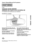
ACCESSORIES
These accessories were available when your snow blade was purchased. They are also available at most Sears
retail outlets and service centers. Most Sears stores can order repair parts for you when you provide the model
number of your snow blade.
WEIGHT
WHEEL WEIGHT
48" SNOW
BLADE
CARTON
CONTENTS
BRACKET
TIRE CHAINS
(HARDWARE
PACKAGE
2
,
3
SHOWN
ON PAGE
_16
4)
18 __..
©
-21
22
BAG (C)
o_---_r---
REF.
QTY.
DESCRIPTION
REF.
QTY.
¸
..... BAG (D)_j
i
I
11
lO
/
DESCRIPTION
Parts Loose in Carton (used on all tractors)
1
1
Blade Assembly
2
1
Pivot Support Bracket
3
1
Channel Assembly
4
1
Brace Tube (R.H,)
5
1
Brace Tube (L,H.)
6
1
Frame Assembly
Handle Tube
7
1
8
1
Lift Rod
9
1
Blade Pivot Rod
10
1
Cable
Parts in Carton (B) (used on 917 tractors
16
1
Pivot Plate Bracket
Parts in BAG (A) (used on all tractors)
! 1
1
Extension Spring
12
1
Grip Assembly
13
1
Blade Pivot Shaft
23
1
Axle Pivot Bracket
Hardware Package (Shown On Page 4)
14
15
1
2
Blade Adjust Spring
Angle Lock Bars
only)
17
1
Frame Reinforcement
Bracket, R.H.
18
1
Frame Reinforcement
Bracket, L.H.
Parts in Bag (C) (used on 917 & 502 tractors)
19
1
Brace Mount Bracket (L.H.)
20
1
Brace Mount Bracket (R.H.)
Parts in Bag (D) (used on 502 & 536 tractors)
21
1
Frame Bracket (L.H,)
22
1
Frame Bracket (R.H.)
Part in Bag (E) (used on 502 tractors only)
NOTE: Not all parts and fasteners will be used for
any one particular tractor fit-up.
B-_
P-@® ,--®@®®_
N
_
c-
'--'
o-_
FIGURE 1
'-ZJ
_
_
o-_
_.REF.
A
B
C
D
E
F
G
H
I
J
K
L
M
N
O
P
Q
R
S
T
U
V
W
X
Y
Z
AA
AB
AC
O-T_
t-................... D,,E,8,,.CRIP_TION
..............
1
Spring Mount Rod
2 [ Palnut, 3/8'"
2
Cotter Pin 1/8" x 1-1/4"
1
Angle Lock Spring
2
Cable End Fitting
4
Hex Jam Nut 5/16 Thread
1
Spacer, 9/16" OD x 5/8" LG.
1
Hex Bolt, 5/16-18 x 1-1/2"
5
Hex Lock Nut 5/16-18 Thread
1
Cable Mount Bracket
1
Hex Bolt 1/4-20 x 1-1/4"
3
Hex Lock Nut 1/4.20 Thread
2
Spacer, 9/16" OD x 1" LG.
2
Carriage Bolt 3/8- ! 6 x 1-1/4"
4
Lock Washer 5/16"
22
Hex Lock Nut 3/8-16 Thread
4
Hairpin Cotter
1
Channel Pivot pin
2
Hex Bolt, 3/8-16 x 3/4" LG.
14
Hex Bolt 3/8-16 x 1"
2
Hex Bolt 3/8-16 x 2"
4
Spacer, 1" OD x .60 LG.
4
Hex Bolt, 5/1@18 x 3/4" LG.
22
Washer, 3/8" Lock
1
Washer 1/2"
4
Hex Bolt, 3/8-16 x 1-1/4" LG.
1
Hex Bolt, 1/4-20 x 8-i/4" LG,
2
Washer, 3/8" 8TD.
2
Nylon Tie
HARDWARE PACKAGE
T 'r
318" LOOK NUT
U
/
_F
6/18" JAM NUT
I
===-4
112" WASHER
3/8"x 1=
5116" LOCK NUT
f
f
I
i
I
1/4" LOCK NUT
3/8"X2_
818"WASHER
-r--r- /
I
I
I
X
I
5/16"X 3/4"
6/16"X1-1/2"
1' OD X ,60 LQ,
8PACER
FULL SiZE HARDWARE REFERENCE CHART
5/16" LOOKWASHER
9/16" OD X !' LG,
SPACER
818"LOCK WASHER
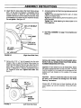
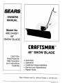
ASSEMBLY INSTRUCTIONS
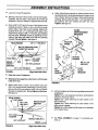
O Attach the left and right hand tube braces on the inside
TOOLS REQUIRED FOR ASSEMBLY
(1)
(1)
of the left and right hand sides of the frame assembly
using four 3/8"x 1" hex bolts, Iockwashers and Iocknuts.
Both tube braces should angle up and out. Do not
tighten at this time. See figure 2,
Pliers
Hammer
Adjustable Wrench (or socket set)
9/16" Open End or Box EndWrench
7/16" Open End or Box End Wrench
1/2" Open End or Box End Wrench
(1)
(1)
(1)
(1)
PIVOT PLATE
BRACKET
Parts Baa Usaae:
\
R.H. TUBE
BRACE LH. TUBE
3/8"x 1.1/4,,
BRACE
You will use the following enclosed
bags based on the first 3 digits of your
TRACTOR model number.
Model No.
502
536
917
DISCARD
REMOVAL
•
UNUSED
BAGS.
OF PARTS
FROM
'}['_-_ _ .J._/_'
q
CARTON
PREPARATION
Remove mower deck or any other attachment you may
have mounted to your tractor. Mark all loose parts and
save for re-assembly.
Refer to owners manual for
removal of mower/attachment.
O
®
_,, FRAME
ASSEMBLY
•
To attach the frame reinforcement brackets in the next
step, the tractor hood can be removed for easier access.
Refer to your owner's manual for removal of hood.
O
Attach R.H. and L.H. frame reinforcement brackets to
front of tractor frame using four 3/8" x 1" hex bolts, four
3/8" lock washers and four 3/8" lock nuts. Do not
tighten. See figure 3.
3/8" LOCK
WASHER (4) =
ASSEMBLY OF SNOW BLADE TO
MODEL NO. 917
TRACTORS
Use all parts
parts in Bag
Discard Bag
Not all parts
used.
3/8" LOCK
FIGURE 2
Right hand (R.H.) and left hand (L.H,) are determined from the operators position while seated on
the tractor.
TRACTOR
_
" \ v
3/8" LOCK NUT
PIVOT SUPPORT BRACKET
Refer to carton contents on page 3 and figure I on page
4 for parts and hardware needed to assemble snow
blade.
NOTE:
•
Parts Bags Used
A, C, D and E Only
A and D Only
A, B and C Only
3/8"x i"
3/8" LOCK
NUT
(4)
/
"__
HEX BOLT =(4) /_
.-L_
_
packed loose in Carton, and all
(A), Carton (B) and Bag (C).
(D) and Bag (E).
in Hardware Package will be
_
Using the two bottom holes, attach the pivot support
bracket to the front of the frame assembly using two
3/8" x 1" hex bolts, Iockwashers and lock nuts. See
figure 2. Do not tighten till next step.
REII"iF:OARcCKA_I:
ENT
ACTOR
(_ _
Using the two top holes assemble the pivot plate bracket
to the front (inside) of the frame assembly using two
3/8" x 1-1/4" hex bolts, Iockwashers and lock nuts. See
figure 2. Tighten all loose bolts.
FIGURE 3
5
\
R.H. FRAME
REINFORCEMENT
BRACKET
FRAME
(FRONT)
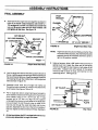
ASSEMBLY INSTRUCTIONS
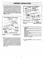
o
Lower the mower lift assembly.
e
Starting at the rear of the foot rest, remove and discard,
if present, the two bolts in the bottom set of holes as
illustrated in figure 4. Repeat on opposite side foot rest,
•
....
Attach blade frame assembly to inside of tractor frame
by aligning holes in pivot plate bracket with holes in front
end of tractor ,frame and holes in frame reinforcement
brackets, Secure using two 3/8" x 1-1/4" hex bolts, 3/8"
flat washers, 3/8" lock washers and 3/8" lock nuts.
Tighten, See figure 6.
Place a 3/8" x 3/4" hex bolt in ear of both brace mount
brackets as shown in figure 4. Now, using the two small
bottom slots in the brace mount brackets, attach both
brackets (R,H and L.H,) underneath both sides of the
tractor frame using four 3/8"x 1" hex bolts, lock washers
and look nuts, (Brackets should be positioned on the
inside of the frame with ears to the rear end pointing
outward,) Do not tighten. See figure 4,
REAR FENDER
FRAME
REINFORCEMENT
BRACKETS
TRACTOR
3/8" x 1" HEX BOLT
BOLTS REMOVED FROM
THESE TWO HOLES
"
BRACE
MOUNT
BRACKET
3/8 FLAT
WASHER
!
FOOT REST
WASHER
3_"LOCK
J
3_"HEXLOCKNUT
3/8" x %1/4"
HEX BOLT
I
3/8" X 3/4" HEX BOLT
FIGURE 4
FRONT-----_
3/8"
LOCK
WASHER
(Right hand side view
•
Raise the mower lift assembly,
•
811debladeframe assemblyundertractor,withthe brace
tubesat the rear.
PIVOT
PLATE
BRACKET
FIGURE 6
Attach brace tube to brace mount bracket using the
3/8" x 3/4" hex bolt already assembled tn previous step.
Secure with a 3/8" lock washer and 3/8" lock nut. Repeat
this step on opposite side, Do not tighten at this time.
See figure 5,
At this time tighten ail of the following bolts previously left
untightened.
Tighten the 4 bolts fastening the frame reinforcement
bracket to the tractor frame.
Tighten the 4 bolts fastening the tube braces to the
frame assembly.
Tighten the 2 bolts fastening the tube braces to the
brace mount brackets.
Tighten the 4 bolts fastening the brace mount brackets
to the tractor frame.
3/8" LOCK
WASHER
_
[
3/8" LOCKNUT
T
_'_
BRACE TUBE (R.H.)
0
FRONT
FIGURE 5
(Right hand aide view)
6
See FINAL ASSEMBLY on page 11 to complete your
hook up,
ASSEMBLY INSTRUCTIONS
ASSEMBLY
OF SNOW
MODEL NO. 502
BLADE
TO
*
TRACTORS
Use all parts packed loose in Carton, and all
parts in Bag (A), Bag (C), Bag (D) and Bag (E).
Discard Carton(B)
Not all parts in Hardware
Package will be
used
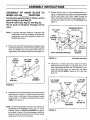
Attach frame brackets (R.H, and L.H.) to the inside of
tractor frame using the front hole inthe brackets and the
hole in each side of tractor frame that is at the front of the
foot rest and the back edge of the engine. See figure 9.
Fasten each bracket with one 3/8" x 1" hex bolt, lock
washer and lock nut: (Note that brackets are positioned
with the bends pointingin, the notched side to the front
and the four holes at the bottom,) 00 not tighten. See
figure 9.
Remove the four bolts which fasten the cross brace to
e
the frame assembly and repos.ition and fasten the brace
using the back set of holes in the frame assembly.
Tighten. See figure 7,
O
Assemble axle pivot bracket to the inside of the front
plate on frame assembly using two 3/8" x l" hex bolts,
3/8'! lock washers and 3/8" lock nuts. Tighten.
See
figure 7.
3/8" x 1" HEX BOLTS
AXLE PIVOT
3/8" x 3/4" HEX BOLTS
3/8" LOCK
WASHER
CROSS
BRACE
!
3/8" LOCK
THIS HOLE
FIGURE 9
LOCK
WASHER
O
FIGURE 7
Using the top and bottom holes on both sides of the pivot
support bracket, attach itto the outside of the front plate
oftheframe assembly using four 3/8" x 1" hex bolts, lock
washers and lock nuts. Tighten.
See figure 8.
3/8" LOCK NUT
Attach blade frame assembly to the tractor frame by
inserting the axle pivot bracket into thehole inthe center
of the axle. See figure 10.
3/8" LOCK
NUT
FRAM E ASSEMBLY
o
•
(Right Hand Side View)
Attach the blade frame assembly to frame brackets
(R.H. and L.H.) using the bottom front hole on each
bracket and the bottom rear holes on both sides of the
frame assembly. Use two 3/8" x 1" bolts, 3/8" locl_washers
and 3/8" lock nuts. DO not tighten.
See figure 10.
AXLE PIVOT BRACKET
AXLE HOLE
3/8" LOCK
WASHER
._
.
3/8" x 1"
.._
HEX BOLT
FRAME
BRACKET (LH.)
3/8" HEX NUT
PIVOT SUPPORT BRACKET
FIGURE 8
FRAME
ASSEMBLY
3/8" LOCK
WASHER
FIGURE 10
HEX BOLT
(Right Hand Side View)
ASSEMBLY INSTRUCTIONS
o
On both sides of tractor, remove and discard the bolts in
the two holes located directly in front and behind the
fenders as shown In figure 11. Insert a 3/8" x 3/4" hex bolt
down through the ear of each brace mount bracket.
Attach the L. H. bracket to the left side of the tractor on
the inside of tractor frame using two 5/16" x 3/4" hex
bolts, lockwashers and lock nuts as shown in figure 11,
Ear of bracket should be to the rear and facing outward,
Repeat for right side using R,H, bracket, Do not
tighten, See figure 11.
HOLES WHE
3/8" x 3/4" HEX BOLT
BRACE MOUNT
BRACKET
3/8" LOCK WASHER
HEX NUT
BOLTS WERE REMOVED
BLADE FRAME ASS'Y
BRACE TUBE (R.H.)
3/8" x 1" HEX BOLTS
FRONT
FIGURE 12
(Right Hand Side View)
,,,,.._
\
O
5/16" LOCK NUT
5/16 LOCK __.'_
WASHER
_
_
_
-,o°/" T
MOUNT
BRACKET
FIGURE 11
O
X 3/4"
HEX BOLT
t
EAR POINTS OUTWARD
(Left Hand Side View)
Attach the brace tubes (L,H. and R.H.) to the outside of
the frame assembly using the front bottom hole in the
frame assembly and the aligned hole through the frame
assembly and the frame bracket as shown in figure 12.
Use two 3/8" x 1" hex bolts, lock washers and lock nuts
on each side. Attach the other end of the brace tubes to
At this time tighten all of the following bolts previously left
untightened.
Tighten the 2 bolts fastening the frame brackets to the
tractor,
Tighten the 2 bolts fastening the frame assembly to the
frame brackets.
Tighten the 4 bolts fastening the brace mount tubes to
the frame assembly,
Tighten the 4 bolts fastening the brace mount brackets
to the tractor,
Tighten the 2 bolts fastening the brace mount tubes to
the brace mount brackets.
• See FINAL ASSEMBLY on page 11 to complete your
hook up.
the brace mount brackets using the 3/8" x 3/4" hex bolts
inserted in previous step, Secure from underneath with
a 3/8" lock washer, and !ock nut on both brace tubes.
See figure 12.
8
ASSEMBLY INSTRUCTIONS
ASSEMBLY
MODEL
OF
NO. 536
SNOW
BLADE
TO
TRACTORS
Use all parts packed loose in Carton, and all
parts in Bag (A) and Bag (D).
Discard Carton (B), Bag (C) and Bag (E).
Not all parts in Hardware Package will be
used.
0'
Position tlie R.H'. and L.H. frame brackets as shown in
figure ! 4, aligning the front holes in the frame brackets
with the rear holes in the frame. Fasten through the
bottom front hole of each frame bracket using a 3/8"x 1"
hex bolt, lock washer and lock nut. Do not tighten. See
figure !4.
FRAME BRACKETS
3/8" LOCK
NOTE: To provide adequate clearance underneath this
model tractor, it will be necessary to reverse the
arrangement of the frame assembly. Refer to the
following instructions.
O
Remove the four bolts fastening the pivot support plate
to the frame assembly. Turn the frame assembly upside
down and refasten the pivot support plate using the
original bolts, lock washers and lock nuts. See figure 13.
PIVOT
SUPPORT
PLATE
3/8" LOCK
WASHER
3/8"
LOCK
NUT
i
R.H, & LH.
NUT
PIVOT
PLATE ..._
SUPPORT
_)
_
_
HEX BOLT
3/8" LOCK
WASHER
PIVOT SUPPORT BRACKET
FIGURE 14
(Left Hand Side View)
Attach the L.H. brace tube to the outside of the frame
assembly as shown in figure 15, using two 3/8" x 1" hex
bolts, lockwashers and lock nuts. The slight bend in the
brace tube should angle out, away from the frame
assembly. Do not tighten. Repeat for R.H. side. See
figure 15.
/
3/8" x 1"
HEX BOLT
FRAME
ASSEMBLY
R.H. FRAME
BRACKET
FIGURE 13
O
L.H. FRAME
3/8" LOCK
NUTS
L.H,
Assemble the pivot support bracket to the pivot support
plate as shown in figure 14. Fasten through the top and
bottom holes on both sides of the pivot support bracket
using four 3/8" x 1" hex bolts, lock washers and lock nuts.
Tighten. See figure 14.
TUBE
3/8" LOCK
WASHERS
NOTE: The following assembly requires careful attention to
identification and placement of R.H. and L.H. frame
brackets. (Refer to CARTON CONTENTS on page 3
and to figure 14 below.) The notched edges of the frame
brackets should face forward and the bends should
angle away from the frame assembly.
BRACKET
FIGURE 15
3/8" X 1"
HEX BOLTS
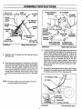
ASSEMBLY INSTRUCTIONS
e
e
Attach the R,H, brace tube to the tractor frame using a
3/8" x 2" hex bolt, two spacers, a lockwasher and a
Iocknut as shown in figure 16, Use the empty hole
located to the rear and to the inside of the foot rest, Hole
isconcealed by the rubber foot pad. Repeat for left side,
Do not tighten, See figure !6,
At thistimetighten allofthe following boltspreviouslyleft
untlghtened,
Tighten the 2 boltsfastening the R,H, and L.H. brace
tubesto the tractorframe,
Tighten the2 boltsfasteningtheframeassembly to the
frame brackets,
Tighten the 4 boltsfastening the brace tubes to the
frame assembly,
8/8" x 2" HEX BOLT
f------REST
•
See FINAL ASSEMBLY on page 11 to complete your
hook up.
9/I 6"
'
___PACERS
(2)
3/8" LOCK NUT
I
I
IIIIIIIII
II
i
I
FIGURE 16
O
,
..............
(Right Hand Side View)
INSTALLING WHEEL WEIGHTS (PURCHASED SEPARATELY) ON ALL WHEEL STEER TRACTORS: MODEL
NUMBERS BEGINNING WITH 536,..
Remove the 7/16" x 1" bolt (if present) from the hole
located in the L.H. side of the tractor frame, below the
engine and just ahead of the foot rest, Attach the front
hole In the L.H, frame bracket to this hole as shown in
figure 17, using a 3/8" x 1" hex bolt, Iockwasher and lock
nut. Repeat for other side. Tighten both sides. See
figure 17.
Installation of rear weights to the "All Wheel Steer" Series
536 tractor requires the use of (4) 3/8" x 6" bolts. The bofts
must be inserted from the inside with the flat washers, lock
washers and nuts installed on the outside of the wheel
weights,
CAUTION:
Failure to install the bolts from the inside
will lock up the wheels and damage the "All Wheel
Steering" mechanism.
LOCK
%
3/8" X 1 "
HEX BOLT
If these 3/8" x 6" bolts have not been furnished with the
wheel weights, call Lemont industries (Phone #815-6342214)
3/8"
LOCK
NUT
BRACKET
(L.H.)
FIGURE 17
(Left Hand Side View)
10
ASSEMBLY INSTRUCTIONS
.........
_-
iiii
|_
..............
r'
_
i
,,,,,
,=,
,,r
I
FINAL ASSEMBLY
PIVOT
BRACKET
O
Assemble the two angie look bars together as shown in
figure 18, so that all holes are aligned, Use one 3/8" x 11/4" carriage bolt, one 8/8" look washer and one 3/8" hex
lock nut, Be sure to Insert bolt from side Indicated, Do
CHANNEL
I_"LOCK
NUT
not tighten at this time, See figure 18,
mM'
l=
=1
6,NGLE LOCK SPRING
3/8" HEX NUT
3/8" LOCK WASHER
BRACKET
(A)
3/8" CARRIAGE BOLT
1" SPACERS (2)
FIGURE 19
NOTE:
LOCK SPRING
ANGLE
BARS
(RlghtHandSideVtew
Hold the angle lock bars so that the square holes are at
the top_ Hold the angle lock spring so that the opening of
the round hook is facing up, Insert the straight hook end
of the spring through the middle hole In both angle lock
bars as shown Enfigure 18.
O
O
•
1/4"x 3-1/4" HEX BOLT
(Right' Hand Side View)
Angle lock bars should pivot freely; and when they
are pulled all the way back, the channel/pivot plate
assembly should be unlocked and free to pivot to
right or left position notches.
FRONT--_
O
FIGURE18
BRACKET (A)
Assemble round hook end of angle lock spring up
through the hole in bracket (A), which is mounted on the
pivot bracket. See figures 18 and 19.
Pull on angle lock bars to extend spring just enough to
allow insertion of bars down through slot in channel and
. pivot bracket. Using a 1/4" x 3-1/4" bolt, two 1" Iong
spacers and a 1/4" lock nut, align the two spacers
underneath the channel on both sides of the angle lock
bars and insert the bolt through holes in sides of the
channel and through the angle lock bars and the two
spacers, Assemble the lock nut to the bolt on outside of
channel, Tighten so that lock bars pivot freely. See figure
19,
At this time tighten the 3/8" carriage bolt and hex nut
previously assembled to angle lock bars,
Using a hammer, drive a 3/8" palnut onto one end of
spring mount rod, Insert the other end of the spring
mount rod through the rear holes on both sides of the
pivot plate. Support end ('with palnut) of the spring
mount rod with a block of wood, and hammer on the
remaining palnut. See f_gure 20.
3/8" PALNUT
SPRING
MOUNT
ROD
3/8" PALNU1
FIGURE 20
(Top View
ASSEMBLY INSTRUCTIONS
@
Assemble 3/8" x 1-1/4" carriage bolt through square hole
in cable mount bracket and through square hole in angle
lock bars as shown in figure 21. Note that the top bolt
faces in opposite direction. Using pliers hold the cable
mount bracket in position, angling down towards small
hole in channel as shown in figure 21, and secure with
a 3/8" lock washer and a 3/8" lock nut, Tighten. See
figure 21. See also figure 23 for correct angle for cable
mount bracket.
3/8" x 1-1/4"
CARRIAGE BOLT
@
Assemble ball end of control cable up through hole in
cable end fitting and pull till ball slips inside curled edge
of fitting as shown in figure 23. Note: If bail wont slip
under edge of Curl it will need to be inserted through open
end of curl. See figure 23
O
Assemble 1/4" x 1-1/4" hex bolt down through the cable
end fitting, the 5/8" long spacer and the left hand hole in
the channel assembly. Secure with a 1/4" hex lock nut,
See figure 23. Tighten.
NOTE: The other end of the control cable will be
attached in a later step.
ALIGN CABLE MOUNT
BRACKET WITH HOLE
ANGLE LOCK BARS
1/4" x 1-1/4"
HEX BOLT
CABLE END
FITTING
SPACER
3/8" LOCK
NUT
3/8" LOCK
WASHER
_365_
CHANNEL
;SEMBLY
FRONT
FIGURE 21
(Right Hand Side View
J
HOLE
[
@
?
Assemble one 5/16 jam nut approximately 3/4" onto
threaded end of control cable. Assemble threaded cable
end through round hole in Cable mount bracket as shown
in figure 22, and secure with another 5/16 jam nut.
Tighten. See figure 22.
1/4" HEX LOCK NUT
FIGURE 23
REAR ---_
(Left Hand Side View)
NOTE: Some adjustment of jam nuts may be required after
blade assembly is completed.
CABLE MOUNT
BRACKET
5/16" J_,M NUT
__
_--
_ _[111
_=. _
_
Insert a 1/8" x 1-1/4" cotter pin down through hole
nearest to bend in blade pivot shaft and spread end.
Attach blade assembly to channel assembly by inserting
the blade pivot shaft from the left side (bend facing up)
through the notched holes in the blade and channel
assemblies. Secure with another 1/8" x 1-!/4" cotter pin
through the end hole in pivot shaft. Spread end of pin.
See figure 24.
@
Attach blade adjust spring over spring mount rod as
shown in figure 24. Remove plastic cap, and one 3/8"
hex nut from bolt assembled in spring. Adjust the remaining 3/8" hex nut down approximate[y I "onto the bolt
threads, Assemble bolt up through the hole in top edge
of blade and hold in place with the 3/8" hex nut removed
earlier. Tighten 3/8" hex nut on top edge of blade down
against the bottom 3/8" hex nut. Replace plastic cap
over end of bolt threads. See figure 24.
3/4" -_
o_[]TITFg]TmTN==o
,,
5/16
JAM NUT
t
CHANNEL ASSEMBLY
FIGURE 22
@
REAR "_
(Left Hand Side View)
12
ASSEMBLY INSTRUCTIONS
_
3/8" HEX NUT
1
BLADE
PIVOT _
SHAFT
PIVOT SUPPORT
BRACKET
flop)
1/8" x 1.1/4"
COTTER PIN--
PLASTIC
CAP
_/.
3/8" HEX NUT
I
L
I
(BOTTOM)
\
SHOE
CHANNEL
ASS'Y
0
BLADE
ASS'Y
FIRST HOLE
IN CHANNEL
_,._J_
& SLOT _N
_
PIVOT SUPPORT
BRACKET SHOULD /
BLADE ADJUST
SPRING
SPRING
MOUNT ROD
FIGURE 24
1/2" WASHER
BE
1/8" x 1-1/4"
COTTER PIN
ALIGNED
COTTER
FIGURE 25
•
Assemble the 1/2" washer onto the channel pivot pfn,
See figure 25.
®
Attach the channel assembly to the tractor by placing the
end of the channel assembly up inside the pivot support
bracket on the tractor, Align the second hole from the
end in the channel assembly with the front hole in the
pivot support bracket and insert the channel pivot pin
through from the _eftside. Secure with a hairpin cotter
pushed all the way through to the loop end. See figure
25.
_"
f._
SMALLEST
HOLE
CHANNEL
ASSEMBLY
*_
PUSH THROUGH
TO LARGE LOOP
(Right Hand Side View)
""
" "" _"
ALTERNATIVE
HAIRPIN DESIGN
(Right Hand Side View)
o
To assemble lift handle to blade, assure that holes in end
of channel assembly are aligned with clearance slots in
stdes of pivot support bracket as shown tn figure 25.
From the left side insert the bracket end of the flff rod
through the holes In the channel assembly. Next, atlgn
the hole in the lift rod bracket with the lift link (preassembled to the pivot support bracket). Secure with a
hairpin cotter inserted up through the cross hole in the lift
link pin aJIthe way to the loop end of the hair pin cotter.
See figure 26.
O
Using the furnished grease packet, apply a light coating
of grease to the straight upper portion of the lift rod. Slide
lift handle tube onto the lift rod. See figure 26.
NOTE: All hairpin cotters on this snow blade should be
pushed through to their loop end.
3KET
IN co'rrER
FIGURE 26
13
(Left Hand Side View)
ASSEMBLY INSTRUCTIONS
To attach loose end of cable to handle assembly, pass
cable around outside and underneath handle assembly
as shown in figure 26. Mount one 5/16" jam nut approximately 3/4" onto threaded end of control cable. Insert
threaded end of cable up through cable mount ear on
handle assembly and secure with a second 5/i6" jam
nut. Tighten. See figure 27.
NOTE: Some further adjustment may be required after
blade assembly ]s completed.
HANDLE ASS'Y
BALL
END
)
5/16" _
JAM NUTS
Raise the blade to the transport position by pulling
back and down on the lift handle tube. See figure 30.
(This wilt require extra effort since the extension spring
is not yet attached.)
BLADE PIVOT ROD
HAIRPIN
COTTER
FIGURE 27
LIFT HANDLE
TUBE
EXTENSION
SPRING
PLASTIC
TIES
(Right Hand Side View
0
Attach lock release grip assembly to handle assembly
using one 5/16" x 1-1/2" hex bolt and one 5/16" hex lock
nut. Do not overtighten lock nut; grip assembly must
pivot freely. See figure 28.
o
Assemble ball end of cable to a cable end fitting as was
done previously to other end of cable. Secure cable end
fitting to weld bolt on lock release grip with a 1/4" hex lock
nut. Do not overtighten lock nut; cable fitting must pivot
freely. See figure 28,
5/16" x 1.1/2"
HEX BOLT
HAIRPIN
BLADE
PIVOT SHAFT
CHANNEL ASS'Y
PIVOT SU PPORT BRACKET
FIGURE 29
1/4" WELD.
BOLT
CABLE END
FITTING
CABLE
/
5/16" HEX
LOCK NUT
HANDLE
ASSEMBLY
FIGURE 28
O
Use the two plastic ties to 'h01dthe cable securely to the
outside of the handle tube and away from the tractor to
avoid direct heat from the tractor muffler. See figure 29.
HANDLE
GRIP
LOCK
RELEASE
GRIP
Attach the long end of the blade pivot rod down through
the blade pivot shaft. Attach the short end ofthe pivot rod
to the lift handle tube. Secure both ends with a hairpin
cotter pushed through to loop end. See figure 29.
Attach the long end of the extension spring to the upper
hole in the pivot support bracket and the short end to the
center slot in the channel as shown in figure 29.
CABLE MOUNT EAR
n
O
_1_
CABLE END
FITTING
(Right Hand Side View
14
(Left Hand Side View)
|ill
ir
,
:
i
{_=
'
'
,_,,
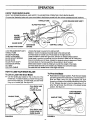
OPERATION
KNOW YOUR SNOW BLADE
READ THiS OWNER'S MANUAL AND SAFETY RULES BEFORE OPERATING YOUR SNOW BLADE.
C£mpare the illustration below with your snow blacle to familiarize yourself with the various controls and their locations.
HANDLETUBE
LOCK RELEASE GRIP ASS'Y,
BLADE PIVOT ROD
ANGLE
LOCK
BARS
BLADE
ADJU, I
SPRING
BLADE SHOE
BLADE PIVOT SHAFT
LOCK RELEASE GRIP ASS'Y,
HANDLE TUBE
BLADE PIVOT ROD
ANGLE LOCK BARS,: :
BLADE ADJUST SPRING
BLADE SHOE
BLADE PIVOT SHAFT
EXTENSION SPRING
LIFT ROD
CONTROL CABLE
EXTENSION
SPRING
Unlocks the blade to swivel to the right and left.
Raises or lowers the blade and pivots blade to the right and left,
Connects blade to handle tube, Pivots blade to the right and left,
Locks the blade In either the right hand, left hand or straight ahead position,
Holds blade in position but permits it to pivot forward to pass over an obstruction.
Ground contacting part of blade. Adjusts for adequate ground clearance of blade.
Connects blade to channel assemb2y. Allows blade to pivot forward.
Makes blade easier to raise by helping to counter the weight of the blade.
Connects blade channel to the handle tube, Raises and lowers the blade.
Connects the look release lever to the angle lock bars.
HOW TO USE YOUR SNOW BLADE
To Pivot the Blade
To Lift or Lower the Snow Blade
•
•
Use the handle grip located on the on the end of the
handletube. To raise the blade, pull back while pushing
down on the handle grip. To lower blade, pull back while
lifting up on handle grip, See figure 30,
PULL BACK AND
LIFT UP TO
LOWER BLADE
Raise blade to transport position. Push the lock release
grip down against the handle tube to unlock the blade. To
pivot the blade, keep the grip depressed and push
forward or pull back on the handle tube sliding italong the
lift rod. Release the grip to lock the blade when it is in
either the right hand, the left hand or the straight ahead
position. See figure 31.
LOCK RELEASE
GRIP ASSEMBLY
HANDLETUBE
HANDLE TUBE
\
PULL BACK AND
PUSH DOWN TO
RAISE BLADE
ROD
FIGURE 30
FIGURE 31
1R
OPERATION
NOTE:
Wheel weights and tire chains must be used with
your snow blade for traction, These accessories
are available at your nearest Sears retail store.
If the model of your tractor begins with #536
(model number found in your owners manual or on
the model plate decal), then you will need to use
the 6" bolts included in your wheel weight kit and
discard the longer 8" bolts. Use as instructed to
mount wheel weights to the rear wheels of your
tractor,
CAUTION:
KNOW
THE TERRAIN.
SLOPES OR DROP OFFS WHICH MAY
AVOID
EXCEPTIONALLY
STEEP
BE
HIDDEN
BY THE SNOW.
NEVER RUN THE SNOW BLADE INTO
HEAVY MATERIAL AT HIGH SPEED.
CAUTION: INSPECTTHEAREATO
BE
WORKED
CAREFULLY
BEFORE
OPERATING
THE SNOW BLADE.
AVOID PIPES, ROOTS, CURBS OR
OTHER HEAVY OBSTRUCTIONS.
CAUTION: ALWAYS LOWER BLADE
TO GROUND
BEFORE LEAVING
TRACTOR.
Using the Snowblade
•
Prepare lawn tractor engine for cold weather using
instructions furnished with the lawn tractor.
•
Always begin with transmission in first (low) gear and
gradually increase speed as required.
•
DO NOT repeatedly push snow in the same direction
causing excessive build up with each successive pass.
•
To reduce icing on blade, allow lawn tractor and blade to
adjust to outdoor temperature before operating,
NOTE:
When working under the hood of a SERIES 536
tractor while snow blade is attached, the hood may
not stay up on its own; therefore, you may need to
lay something (such as a piece of wood) over the
engine housing to keep the hood propped up.
CUSTOMER RESPONSIBILITIES
Lubrication
•
Points
Maintenance
Lubricate the points shown in figure 32 for easier operation. Use the grease packet furnished with the snow
blade for lubrication of the lift handle rod and the lift
handle tube assemblies.
•
HANDLE TUBE
LUBRICATE
\
FIGURE 32
16
During the operating season, check all bolts, nuts and
hairpin cottersto be sure they are secure. For improved
snow removal performance, coat the blade with
automotive type paste wax.
SERVICE.AND ADJUSTMENTS
To Adjust Blade Spring
To Adjust the Biade Pivot Lock Mechanism
®
•
The tension of the blade adjust spring is adjustable to
permit blade to tilt forward to by-pass solid obstrdctions.
To change spring tension (standing in front of blade
assembly), adjust the nuts at upper end of the spring
bolt, turning counter cJookwlse to relieve tension and
clook'wlseto Increase tension, See flgure24on page 13,
the end of the cable extends through the ear, the more
the angle lock bars can retract to disengage from the
slots In the pivot plate, See figure 34,
To Adjust Blade Shoes
•
If the blade will not unlock and pivot, the angle lock
bars are not disengaging from slots in pivot plate. To
correct this condition, adjust the 5/16" hex jam nuts to
draw the end of the control cable back towards the
welded cable mount ear on the handle tube, The less
Blade shoes on ends of blade may be raised for close
work on smooth surfaces or lowered to raise the blade
towork on rough or uneven areas, Make sure both shoes
are set evenly and nuts are tightened securely, See
figure 33,
CABLE MOUNT EAR
51
•
HF.D(
/ e" HEX
• II 5/16"
JAMNUT
/
JAM NUT
C_
I /
_
_
V
CONTROL
CABLE
/
HI
m=,=..
v
FIGURE 34
BLADE SHO]
FIGURE 33
STORAGE
Recommendations When Storing
To Remove Blade From Tractor
•
When the snow blade Is not being used, remove all dirt
and rust and touch up wtth paint,
•
Lower blade to ground with blade in the center (straight)
position,
•
Apply a tight coat of grease or rust preventive to the
blade and oJlall pivot points.
•
•
Store in an area where it is protected from weather,
Refer to figure 29 on page 14.
A, Remove 3/32" hairpin cotter from lower end of
blade pivot rod.
B. Remove 3/32" hairpin cotter from welded link on lift
rod and remove control tube assembly.
C, Remove 3/32" hairpin cotter from channel pivot pin
and remove channel pivot pin.
TROUBLESHOOTING POINTS
Blade is difficult to raise,
--:
7 -
_-7: .............
Blade is difficult to pivot,
r,,r_l
r_,
1, Extension spring is broken/missing,
2, Lift mechanism is binding
1, Replace or reinstall, See page 14,
2, Lubricate as instructed on page 16,
1, Handle tube Is binding on ilft rod,
I. Lubricate handle tube and lift rod as
instructed on page 16.
.....
..........
Blade wit1not pivot,
,,,,,
1, Lock mechanism fs not disengaging.
t7
1. Adjust the pivot look mechanism as
instructed on page 17.
REPAIR PARTS FOR MODEL 486.244281 -48" SNOW BLADE
I.O
"_
O
O_
a_
\
/17
/
!
/
t
ItJ
,e_
_
N
/
1
/
:t-
°
/
/
e3
I
|
_
ID
\
/
I
!
LO
O4
0
18
REPAIR PARTS LIST FOR MODEL 486.244281 -48" SNOW BLADE
REF.
PART
_'J_O
........ NO.
i
2
3
4
5
6
7
8
9
10
11
12
13
14
15
16
17
18
19
20
21
22
23
24
25
26
27
28
29
30
31
32
33
34
35
36
37
QTY,
DESCRIPTION
23965 1 Biade48"................
23956
62980
43080
43079
43064
43081
23070
23970
23957
43262
23131
43352
23958
23130
23966
46066
43070
9466R
44071
43015
44074
7460366
62561
43055
46053
63033
23974
7320153
24023
23960
23962
23961
23964
23963
46048
46047
1
1
10
2
12
4
2
1
1
1
1
1
1
1
1
1
1
1
2
1
1
1
4
2
1
1
1
1
1
1
1
1
1
1
1
REF,
PART
,..........................
NO,
NO,,,
38 46049
Wear Plate 48"
Reinforcement PJate Ass'y
Bolt, Carriage 5/16-18 x 3/4"
Bolt, Carrtage 5/16-18 x 1"
Nut, Hex Lock 5/16-18
Washer, 5/16"
Skid Shoe
Brace, Cross
Push Channel
Nut, Hex Lock 1/2-13
Bolt, Special Pivot
Washer, Flat 7/16"
Plate, Pivot 7 Ga,
Bracket, Spring Mr.
Bracket, Pivot Plate
Shaft, Blade Pivot
Washer, 3/8" STD.
Spring, Blade Adjust
Bolt, Hex 3/8-16 x 3-1/2"
Nut, Hex3/8-16
Plastic Cap
Control CableAss'y
Release Grip Ass'y
Pin, Hairpin Small 3/32"
Spacer, .28 ID x 1"
Lift Handle Rod Ass'y
Axle Pivot Bracket
Extension Sprfng
Pivot Support Bracket
i Plate, Pivot Support
Frame Pivot Support (RH)
Frame Pivot Support (LH)
Bracket, Frame (RH)
Bracket, Frame (LH)
Brace, Tube (RH)
Brace Tube (LH)
39
62972
40
23967
41
23968
42
23151
43
23856
44
44917
45
43010
46
43348
47
746-0260
48
731-0869
49
46471
50
712-0256
51
23658
52
43085
53
43064
54
05762
55
11509-90
56
43013
57
710-0305
58 ' 43086
59
46065
60
63034
61
43182
62
43407
63
43001
64
43054
65
43087
66
43082
67
43003
68
726-0178
69
R19171616
70
45133
71
46071
72
43349
73
24164
74
24165
46813
I9
QTY,
1
t
1
1
2
1
2
3
1
2
1
1
4
1
!
5
1
1
3
2
4
1
1
4
6
18
2
4
30
30
2
1
4
1
1
1
1
1
" DESCRIPTION
Rod, BladePivot ......
Aes'y Lift Handle Tube
Bracket, Brace Mount (rear) (LH)
Bracket, Brace Mount (rear). (RH)
Angle Lock Bar
Spring Mount Rod
Palnut, 3/8"
Cotter Pin 1/8" x 1-1/4"
Angle Lock Spring
Cable End Fitting
_Grip, Plastic
i Handle, Grip 3/4"
Hex Jam Nut 5/16 Thread
Spacer
Hex Bolt, 5/16-1'8 x 1-1/2"
Hex Lock Nut 5/16-18 Thread
Cabte Mount Bracket
Hex Bolt 1/4-20 x 1-1/4"
Hex Lock Nut 1/4-20 Thread
Carriage Bolt 3/8-16 x 1-1/4"
Lock Washer 5/16"
Channel Pivot Pin
Lift link Ass'y
Bolt, Hex 5/16-18 x 3/4"
Bolt, Hex 3/8-! 6 x 3/4"
Hex Bolt 3/8-16 x 1"
Hex Bolt 3/8-16 x 2"
Hex Bolt 3/8-16 x 1-1/4"
Hex Lock Nut 3/8-16 Thread
Lock 'Washer 3/8"
Plastic Tie
Washer
Spacer, 1/2" ID x 1" OD x .60" Lg.
i Bolt, Hex 1/4-20 x 3-I/4" Lg. Gr 5
1/4" x 1" Spring Pin
Bracket, Frame Reinforcement, R.H.
Bracket, Frame Reinforcement, L.H.
Owners Manual