1
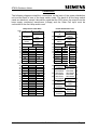
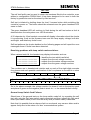
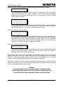
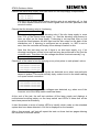
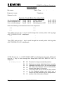
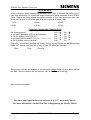
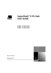
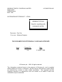
SIEMENS TRAFFIC CONTROLS LIMITED Sopers Lane POOLE Dorset. BH17 7ER 667/HB/27000/100 SYSTEM/PROJECT/PRODUCT: ST800 SIEMENS TYPE 800 TRAFFIC CONTROLLER GUIDANCE NOTES PREPARED: Paul Cox FUNCTION: Software Engineer THIS DOCUMENT IS ELECTRONICALLY HELD AND APPROVED Issue Change Ref. Date 1 n/a 11 March, 1998 © Siemens plc. 1998 All rights reserved. The information contained herein is the property of Siemens plc. and is supplied without liability for errors or omissions. No part may be reproduced or used except as authorized by contract or other written permission. The copyright and the foregoing restriction on reproduction and use extend to all media in which the information may be embodied. ST800 Guidance Notes Introduction The following pages summarize how to use the new ST800 traffic controller from Siemens. It assumes knowledge of the T400 and therefore concentrates on the differences between the two types of controller. Following these pages is a blank Fault Report form. We would be grateful if you could complete a copy of this form and fax it back to Poole when you first install the ST800 controller and after any subsequent visit you make to the site. This will allow us to compile a history of each controller to help diagnose any problems which may occur. For more information, and if you have any problems, do not hesitate to contact me, Paul Cox, on Poole (01202) 782621. The T400 was limited to 16 phases, 4 phases per card, whereas the ST800 lamp switch cards provide 8 phases each, giving a total of 32, with the first 26 phases labelled ‘A’ to ‘Z’ leaving the last six labelled ‘A2’ to ‘F2’. Initialization We strongly suggest that the controller’s ‘Self Test’ facility is used before the controller is powered up normally for the first time. Details of how to use the self test facility are described later in this document. When an ST800 controller is switched on for the first time, it will log a fault and not illuminate the signals without operator intervention. Within this document there is a complete list of all the faults reported by the ST800. It will power-up logging memory faults and ‘New Firmware’ since the contents of RAM are corrupt, i.e. are not what the processor is expecting. These faults can be cleared in the usual way by typing ‘RFL=1↵’ and switching the power off and back on. The clock will also need to be set-up and this is also described in this document. Note that the initialization commands (TKE, etc.) are only required to initialize the controller after its configuration PROM has been changed. These commands will have no effect at any other time, i.e. they can no longer be used to re-initialize a controller which is working normally. Also note that these commands will be rejected with a ‘*L’ error if the signals on/off switch on the manual panel is still in the ‘on’ position. Therefore... Do not change any timings or other settings on the controller on the assumption that they can all be reset back to the PROM settings by entering the initialisation commands. This document also contains information on the LED’s on the front of the main processor card and the connectors on the back of the power distribution units, the lamp switch cards and the main processor card. Page 2 667/HB/27000/100 Issue 1 ST800 Guidance Notes Connections The following diagrams detail the connections on the back of the power distribution unit and the back of one of the lamp switch cards. The back of all the lamp switch cards are identical, except it should be noted that the ZXO wires, the output from the lamp supply monitoring transformer (LSupp) and the Solar Cell input must be connected to the first lamp switch card. PLB 32 28 24 20 16 14 12 10 8 6 4 2 PLA 32 30 28 26 24 22 20 18 16 14 12 10 8 6 4 2 Issue 1 Lamp Switch Card Back z b d EARTH NEUTRAL GREEN SUPPLY R/A ZXO-N SUPPLY (240V) ZXO-N ZXO-LIVE (110V) Sen34+ COMMON LSupp- Sen35+ Sen33+ LSupp+ Sen36+ SOLAR 1R 2R2 2R 1G 1R2 1A 1R1 z 3A 3R2 2R1 3R1 4R 4R2 5R2 5R1 6R1 6R2 6R 7R1 8R1 7R2 8R2 8G 2A d 3R 2G 3G 4A 5A 4R1 4G 5R 5G 6G 6A 7G 7A 7R 8A 8R b 32 30 28 26 24 22 20 Power Distribution Unit z d EARTH IN LIVE LIVE INPUT INPUT NEUTRAL NEUTRAL INPUT INPUT REG. SOLAR SIGN. SUPPLY 16 14 12 10 8 6 4 16 14 12 10 8 6 4 SPARE 2 2 REL-A 32 30 28 26 24 22 20 18 16 14 12 10 8 6 4 2 32 28 24 20 16 12 8 4 ZXO-N 0V 0V 12V P/FAIL REL-B 26 22 16 14 0V 0V 12 5V(CPU) 5V(CPU) 10 24V(DET) SSR 8 5V(ESB) 5V(ESB) 6 REL-DIM 24V(CPU 4 N/C SPARE N/C ZXO-L LSupp+ ) LSupp- z b d DIM COMMON NEUTRAL NEUTRAL RETURNS RETURNS NEUTRAL NEUTRAL RETURNS RETURNS NEUTRAL NEUTRAL RETURNS RETURNS DIM-LIVE DIM-LIVE (240V) (240V) DIM-LIVE R/A (160V) SUPPLY R/A GREEN SUPPLY SUPPLY GREEN 50-0-50V SUPPLY SUPPLY 667/HB/27000/100 30 2 30 26 22 18 14 10 6 Page 3 ST800 Guidance Notes The following diagram shows the connections in the power connector on the back of the main processor card. Any signal name proceded with an exclamation mark (‘!’) is active-low, i.e. 0v is the active state. The values in brackets, e.g. (24v), show the normal voltages expected on the plug in order that it can be checked. Main Processor Card Rear Power Connector 1 0v 2 0v 3 0v 4 5 6 7 8 CPU Card 24v Det 0v Det !SSR (24v) !Dim (24v) !P/Fail (5v) 5v CPU 5v CPU 5v ESB 5v ESB !Rel/A (24v) !Rel/B (24v) Low Batt P/Fail (0v) 9 10 11 12 13 14 15 16 → Main Processor LED’s There are four LED’s on the front of the main processor card. The top one is green and is labelled ‘PP’ for power present. This LED will flash giving a heartbeat indication that the firmware is running normally. If it does not illuminate, then there is no power to the main processor card. Check that controller is powered and that the power connector is inserted into the back of the processor card. The other three LED's are red and identify various fault conditions. The top red LED is labelled ‘SE’ for system error. This will illuminate during the power-up sequence and then will normally be extinguished when the controller is running normally with no faults present in its fault log. The middle red LED is labelled ‘BE’ for bus error. This LED should only illuminate if the processor has problems executing the firmware, e.g. when the firmware PROM is missing. The bottom red LED is labelled ‘WD’ for watchdog. This LED will be illuminated when the hardware watchdog circuit times-out. Note that when the firmware detects a serious fault, it will extinguish the lights and stop ‘kicking’ the hardware watchdog deliberately so that it times-out and also keeps the lights off. Page 4 667/HB/27000/100 Issue 1 ST800 Guidance Notes Self Test The self test facility can be used to check the hardware fitted to the controller, even without a configuration PROM fitted. It has been designed to be used in both the factory by production and on the street by field services. Self test is initiated by holding down the level 3 access button while switching the controller’s power on. The button should be released once the green heartbeat LED starts to flash. The green heartbeat LED will continue to flash during the self test unless a fault is detected when the red system error LED illuminates. A 20 character by 4 line handset connected will display information about the checks it is performing, such as the firmware issue and the lamp supply voltage, both dim and bright, and detail any faults found. Self test performs the checks detailed on the following pages and will report the error messages shown if faults have been detected. Resolving problems with lamp switch cards and triacs: When various tests fail, the handset may display information such as: ← identifies the test which has failed ← outputs from the red voltage monitors ← outputs from the amber voltage monitors ← outputs from the green voltage monitors V/Mons Off...Failed R-00000000+00000400 A-00000000+00000000 G-00000400+00000000 The numbers are in hexadecimal notation and so each of the eight digits encodes four phases and each possible combination of the four phases is encoded to a value as follows:F2E2D2C2 B2A2ZY XWVU TSRQ PONM LKJI HGFE DCBA 0 0 0 0 0 4 0 0 0 1 2 3 4 5 6 7 8 9 A B C D E F ---- ---I --J- --JI -K-- -K-I -KJ- -KJI L--- L--I L-J- L-JI LK-- LK-I LKJ- LKJI So in the above example, the voltage monitor for phase K red on the positive peak and phase K green on the negative peak is stuck on, i.e. the second board is faulty. General Lamp Switch Card Failures: Should one of the general tests on the lamp switch cards fail, try repeating the self test with only the first lamp switch card connected and then repeat this with each board (and ribbon cable) in turn until the faulty card (or ribbon cable) is detected. Note that it is possible that an obscure fault on one board, may cause a latter card to appear faulty due to the nature of a ‘bus’ communications system. Issue 1 667/HB/27000/100 Page 5 ST800 Guidance Notes On power-up, the self test facility... Checks the integrity of the main processor board RAM FAULT PRG PROM FAULT XTL FAULT DPR R/W FAULT All the above faults point to problems internally on the main processor card. Checks communications with the secondary / phase bus processor P/Bus CPU.... If the processor cannot be detected, then the self test will wait indefinitely at this point with the red system error LED flashing. Check that the processor and its firmware are fitted. Examines the lamp switch cards to see how many are fitted No L/S Cards Found No cards were detected, check the ribbon cable. Bad L/S Cards Found e.g. if the first and third cards are detected, but not the second. Waits for ZXO synchronization and checks the mains frequency ZXO Sync’d... If the phase bus processor cannot synchronize to the mains zero cross-over signal, e.g. because the ZXO wires are not connected to the back of the first lamp switch card, then self test will wait indefinitely at this point with the red system error LED flashing. Mains Freq Error If the mains frequency is more than 5% out from either 50Hz or 60Hz. Checks all the ADC test voltages on all of the lamp switch cards ADC Tests....Failed ADC Test Readings 0.0V 2.5V 5.0V B0+ nnnn nnnn nnnn B0- nnnn nnnn nnnn ... .... .... .... If the test fails, then the readings from each board, taken at both the positive and negative mains peaks for each of the three test voltages (0V, 2.5V and 5V) are displayed on the handset. Ideally the values should be 0, 512 and 1024, so try replacing any cards with readings which are very different. If all the readings appear too high or too low, particularly the 2.5V readings, then this may point to a problem with the 5v logic supply. Page 6 667/HB/27000/100 Issue 1 ST800 Guidance Notes Checks that the lamp supply and voltage monitors are detecting no mains L/Supply Off=240V L/Supply Stuck On If a lamp supply is being detected, then this implies that the lamp supply relays are all switched on (very unlikely) or the lamp supply monitoring transformer (in the power distribution unit) or its connection to the first lamp switch card is incorrect. V/Mons Off...Failed R-00000000+00000400 A-00000000+00000000 G-00000400+00000000 If any of the voltage monitors appear to be detecting mains, even though the lamp supply and all the triacs are switched off, then this implies a problem with the hardware on one or more of the lamp switch cards. Initializes the phase bus processor P/Bus Init... LS/Card Fault (Lat) Bad L/S Cards Once initialized, the phase bus processor performs more thorough checks on the lamp switch cards and may detect faults. These tests check the data lines and board select lines using test latches on each card ‘(Lat)’, the address lines to each card ‘(Adr)’ and the ADC test voltages ‘(ADC)’. If more than one test fails, then ‘Bad L/S Cards’ is displayed instead. Checks the monitor validation signal M/V Test.....Failed Mon Val Failed The monitor validation signal is generated by the main processor and travels down the phase bus cables to each of the lamp switch cards, so a failure is probably due to a faulty lamp switch card. At this point, the self test has successfully checked-out the logic side of all the lamp switch cards that it has found. It then displays a scrolling diagonal line on the amber LED’s on these lamp switch cards to prove that it can address all the boards correctly and to show that the first part of the self-test is complete. This pattern remains until the operator presses the level 3 button to confirm that the pattern is scrolling correctly on all the cards fitted and that the self test may switch on the lamp supply and continue its tests. Caution It is essential that the correct number of lamp switch cards have been detected at this point as following this, the self test will start applying mains to the signals Issue 1 667/HB/27000/100 Page 7 ST800 Guidance Notes After the level 3 button is pressed, self test switches on the lamp supply. Towards the end of this second sequence of tests, it tests all the triacs by switching each one on in turn for a very short period of time. If standard HI 12V halogen lamps are used (with a transformers in the signal heads), then this pulse will not be seen on the street and so the signals need not be covered. However it may be possible to see the pulse on lamps that are not driven by any transformer, i.e. that run directly off the 240V. If in doubt, all non-HI signal heads, i.e. 240V lamps, should be covered before proceeding any further with the self test. Self test switches on the lamp supply and then... checks that the voltage monitors still show no mains (triacs still switched off) V/Mons Off...Failed R-00000000+00000400 A-00000000+00000000 G-00000400+00000000 If any of the voltage monitors appear to be detecting mains, then it would imply that those triacs are not holding off the mains and those lamp switch cards should be replaced. Checks that it can detect a lamp supply L/S Monitor Reversed The wires from the lamp supply monitor transformer in the power distribution unit to the first lamp switch card (LSupp) are connected the wrong way round. ZXO Wires Reversed The ZXO wires from the power distribution unit to the first lamp switch card are connected the wrong way round. L/S Monitor Fault The lamp supply can be detected on the voltage monitors, but no signal is present from the lamp supply monitoring transformer. Check the transformer and its connections. L/Supply Failure No lamp supply has be detected by the lamp supply monitoring transformer but further investigations by the self test facility cannot determine the cause. Check the lamp supply circuits relays, fuses, etc., in and around the power distribution unit. Page 8 667/HB/27000/100 Issue 1 ST800 Guidance Notes Checks that each lamp supply relay can switch off the lamp supply independantly SSR Fault Relay A Fault Relay B Fault Failure of any of these tests implies that the relay is not switching off, i.e. that it is either welded closed or the control signals from the main processor card are stuck active. Checks that the dimming relay is functioning Dimming Fault A fault is only logged on the dimming relay if the dim lamp supply is more than 75% of the normal lamp supply, i.e. that the dimming relay seems to have no effect on the lamp supply. If dimming is not required, then no link should be fitted between the dim input and the dim output on the back of the distribution unit. If dimming is configured as not present, i.e. KDP is set to zero, then the controller will simply never attempt to switch to dim. Note that this test does not fail if there is no dim lamp supply, e.g. if no dimming transformer is fitted, since self test may be performed on the just the controller rack. Therefore, the dim voltage should be checked manually, e.g. Dim L/Supply=160V Checks all of the triacs in turn by applying a very short pulse to each phase’s colour A/Red:Extra Sigs On R-00000001+00000001 A-00000001+00000001 G-00000001+00000001 A fault will be logged if extra signals are detected as on when one particular aspect is pulsed. This would normally imply a short-circuit in the street cabling or a open neutral connection. No Voltages On... R-00000F00+00000F00 A-00000F00+00000F00 G-00000F00+00000F00 A fault will also be logged if no voltages were detected, e.g. when one of the fuses on one of the lamp switch cards has blown. At the end of the test, the self test switches off the lamp supply and displays a multicoloured scrolling pattern on the lamp switch card LED's to show that all the tests have passed successfully. It also illuminates a series of amber LED's to identify which cards on the extended system bus have been detected. A full list is displayed on the handset. After a few seconds, self test will repeat the tests on these last two pages allowing the controller to be soak tested. Issue 1 667/HB/27000/100 Page 9 ST800 Guidance Notes Handset Introduction Unlike the T400, no prompt is automatically displayed when the handset is first connected to the controller. The ST800 handset communications can work at either 1200, 9600 or 19200 baud and therefore the controller waits for the operator to press ‘BackSpace’ (or ‘Delete’) a few times so that it can determine what baud rate is being used. Note that on the old-style 14 character Oyster handset, the first press of the ‘BS’ key tells the Oyster to transmit and receive at 1200 baud. All key presses are ignored until this key is pressed, making it appear like either the handset or the controller is not responding. Also note the ST800 defaults to producing 20 character wide displays on the assumption that a newer 20 character by 4 line handset is being used, rather than the older single line, 14 character handsets. This extra room allows the controller to display more information within each handset command. To reduce the display width back to 14 characters, simply enter ‘WID=14↵’. The same command can be used to increase the display width, e.g. enter ‘WID=80↵’ when a PC / IPT is being used as a handset. Setting the Date and Time Entering ‘TOD’ now displays the date as well as the time. If the display width has been reduced to 14 characters, then only the time is initially displayed, and the ‘+’ key must be used to display the date and the day of week. To set the time or date, simply press ‘=’ and enter time (or date) directly, there is no need to use the T400 commands STM and CKL. Note that the following keystrokes will still work on a 14 character terminal since the date, time or day of week can all be changed while displaying any part of the time. For example:Keystrokes TOD↵ = Display Mon01JAN90 00:03:25 TOD= TUE3MAR98↵ Tue03MAR98 00:03:32 = 11:35↵ Page 10 TOD= Tue03MAR98 11:35:00 667/HB/27000/100 Issue 1 ST800 Guidance Notes Fault Log The ST800 uses the same fault log commands as on the T400. Therefore to display the currently active fault flags, enter ‘FFS↵’ (fast fault scan), and for the fault data, enter ‘FDS↵’ (fast data scan). The ‘+’ and ‘-’ keys can then be used to scroll through the active faults. For backwards compatibility, the ‘FLF’ (fault log flags) and ‘FLD’ (fault log data) handset commands still exist. The ST800 also contains a timestamped historic rolling log which can be viewed using the command ‘LOG↵’. When ‘LOG↵’ is first entered, the most recent entry is displayed. To move through the historic log, use the ‘+’ and ‘-’ keys as normal. A timestamped entry is added to the log when:• the controller is initialised, i.e. on first time power-up or after a config. change, • the power is switched off and back on, and whether a self test was performed, • when any FLF/FLD fault is set or is cleared, • when the lamp monitor is reset, • when any lamp fails or is replaced, • when any detector input fails DFM, when it next changes state, and when the fault is eventually cleared, Note that this rolling log is not cleared when the configuration PROM is changed. The controller remembers your last position in the log, so if you type ‘LOG’ again after another command is used, it will return you to your last position in the log. To return to the end of the log, press <SPACE>. If the ‘+’ key is then used, then the most recent entries are displayed as before, but if the ‘-’ key is used, then the log can be viewed in the reverse direction, starting with the oldest entry still present in the rolling log. However, if the power is switched off and back on, or the handset is disconnected, then the first time that ‘LOG↵’ is entered, the most recent entry is always displayed. The table on the following pages summarizes the ST800 fault log. The ‘FLF’ column identifies the fault log flag number and the ‘FLD’ column identifies the associated fault log data byte(s). The ‘ABBR’ column shows the abbreviation that appears along side the fault report in the commands ‘FFS’ and ‘LOG’. Issue 1 667/HB/27000/100 Page 11 ST800 Guidance Notes FLF ABBR 0 1 PBUS 2 3 CORR Page 12 FLD 10-12 Description Not Used Not Used Phase Bus Processor Checks Fail Fault log flag values for faults detected by the Phase Bus Processor are numbered below 200 and the currently defined values follow:FLF 2:1 - RAM fault FLF 2:2 - Firmware PROM checksum fault FLF 2:3 - Incompatible configuration FLF 2:4 - Configuration checksum fault FLF 2:5 - Message time-out (main CPU stopped) FLF 2:6 - Unknown message from main processor FLF 2:7 - Internal software fault FLF 2:10 - Lamp switch card fault, not enough cards? FLF 2:13 - Unexpected red current fault FLF 2:20 - Correspondence fault FLF 2:21 - Half cycle correspondence fault FLF 2:22 - Conflict fault FLF 2:23 - Any green fault FLF 2:24 - Last red fault FLF 2:25 - ZXO missed fault FLF 2:30 - Shutdown message from main processor Fault log values of 200 or above are generated by the main processor when it detects a problem:FLF 2:200 - DPR Memory Fault FLF 2:252 - Monitor Validation tests failed FLF 2:253 - Incompatible Phase Bus firmware FLF 2:254 - Comms lost during normal operation FLF 2:255 - Phase Bus CPU not detected on power-up 92-127 Correspondence Failure (e.g. phase E green half cycling): FLD 92:00111001 - Requested reds A-H FLD 93:00111001 - Actual reds A-H, +ve peak FLD 94:00111001 - Actual reds A-H, -ve peak FLD 95:00100010 - Requested ambers A-H FLD 96:00100010 - Actual ambers A-H, +ve peak FLD 97:00100010 - Actual ambers A-H, -ve peak FLD 98:11000100 - Requested greens A-H FLD 99:11010100 - Actual greens A-H, +ve peak FLD 100:11000100 - Actual greens A-H, -ve peak FLD 101:11100000 - Requested reds I-P ...through to... FLD 127:00000000 - Actual greens Y-F2, -ve peak Note that the historic rolling log will attempt to summarize any correspondence error rather than hold all the above fault log data, e.g. ‘E/GRN +/-VE’. 667/HB/27000/100 Issue 1 ST800 Guidance Notes FLF ABBR RLAY 4 FLD 3 5 CFT 6 7 NZXO RTC - 8 WDOG 4 9 10 Issue 1 50-65 - Description Relay Tests Failed: The relay tests try to detect short-circuits while the controller is operating normally with the lamp supply on. By closing all but the relay under test, the lamp supply should not be present unless that relay is short circuit. Note that if any relay is stuck open circuit, then the lamp supply fault (FLF17) will detect no lamp supply. The fault log data will indicate the detected fault: FLD 1:00000001 - Relay A appears to be short circuit FLD 1:00000010 - Relay B appears to be short circuit FLD 1:00000100 - SSR appears to be stuck short circuit Note that the test on the SSR may fail if there are no lamps connected to the controller. Green Conflict Detected: This fault indicates that the main processor detected a green conflict in the lamp states it requested. The first 4 bytes show the conflicting phases. FLD 50:01000100 - Conflicting phases A-H FLD 51:00000000 - Conflicting phases I-P FLD 52:00000000 - Conflicting phases Q-X FLD 53:00000000 - Conflicting phases Y-F2 The next 12 fault data bytes show the requested lamp states: FLD 54:00111001 - Requested reds A-H FLD 55:00100010 - Requested ambers A-H FLD 56:11000100 - Requested greens A-H FLD 57:11100000 - Requested reds I-P ...through to... FLD 65:00000000 - Requested greens Y-F2 No ZXO detected RTC Power Fail Exceeded Configured Time - clock needs setting up. Watchdog Tripped FLD 4:00000001 - hardware watchdog timed-out FLD 4:00000010 - TWD=1 entered on handset FLD 4:00000100 - 20ms execution count incorrect FLD 4:00001000 - 200ms execution count incorrect FLD 4:00010000 - ZXO/peak execution count incorrect FLD 4:00100000 - Problem with the main CPU operating frequency FLD 4:01000000 - Not Used FLD 4:10000000 - 200ms routines have stopped Not Used Not Used 667/HB/27000/100 Page 13 ST800 Guidance Notes FLF ABBR MEM 11 FLD 5 12 13 14 15 16 17 DFM IOB CFGM NEWC NEWF LSUP 20-31 79 - 18 19 20 21 PDFM SDEP SDEF CPAT 32 6 7-9 22 RLM 83-90 23 24 25 26 PED LRT LGRN HURY 16-17 - Page 14 Description Memory Fault: The allocation of the fault data will change: FLD 5:00000001 - Program PROM checksum failure FLD 5:00000010 - Config. PROM checksum failure FLD 5:00000100 - RAM read/write test failure FLD 5:00001000 - RAM junction data corrupt FLD 5:00010000 - RAM timings data corrupt FLD 5:00100000 - RAM rolling log or time/date corrupt DFM Failure (FLD 20 for port 0 to FLD 31 for port 11) Expansion I/O Board Missing (as T400) On-Street Config. Mode Active (not available in the UK) Configuration PROM Changed, enter the initialization codes New Firmware Installed (or RAM corrupt on power-up) Lamp Supply Failure: The lamp supply has dropped below a configurable threshold (i.e. mains supply below thresholds set by LBT and LDT) or is simply not present (e.g. fuse blown). Priority DFM Failure SDE/SA Board Failure On Power-Up SDE/SA Board Operating Failure Configuration / Firmware Not Compatible Fault data consists of a fault id code (FLD7) plus two data bytes:0 - No Fault 1 - Compatibility Number (Firmware and Config. Numbers) 2 - Facilities Table (Entry Number and Value) 3 - Unknown Configuration Item (2 Byte Item Identity) 4 - Invalid Configuration Data (2 Byte Item Identity) 5 - Lamp Sequence Command (Phase and Command) 6 - Conditioning Command (Command Code and ‘0’) 7 - Conditioning Timer Out of Range (2 byte timer number) 8 - Access Outside Conditioning Array (2 byte offset) RLM Failure: FLF 22:1 - 1st red fail active. FLF 22:2 - 2nd red fail active. FLF 22:3 - 1st and 2nd red fail active. The fault log data will indicate on which phases the red lamp failures have occurred: FLD 83:11000011 - 1st/2nd red fails on phases A-D FLD 84:00110000 - 1st/2nd red fails on phases E-H FLD 85:00000000 - 1st/2nd red fails on phases I-L FLD 86:00000000 - 1st/2nd red fails on phases M-P ...through to... FLD 90:00000000 - 1st/2nd red fails on phases C2-F2 Special Conditioning - Pedestrian Controller Fault Special Conditioning - LRT Fault Special Conditioning - Limit Green Watchdog Special Conditioning - Hurry Call Monitor Fault 667/HB/27000/100 Issue 1 ST800 Guidance Notes FLF ABBR 27 SCF1 28 SCF2 29 FLSH 30 to 37 38 NDIM 39 40 to 46 47 48 49 50 51 52 53 54 55 56 57 58 59 60 61 62 63 DIM+ FLD 18 19 - Not Used - No Dim/Bright Changes No dim/bright changes were detected in a 24 hour period although dimming is configured, see KDP. If either FLF 38 or FLF 39 is set, then the controller will be forced into the bright state. Too Many Dim/Bright Changes The number of dim/bright changes detected in a 24 hour period exceeds the configured limit, see KDL. If either FLF 38 or FLF 39 is set, then the controller will be forced into the bright state. - UINT FREQ RTCH BATT SDEN SDED LINK LMUF LAMP 78 76-77 80 (KLD) PUFA PUFB ANCL IMU 81 82 - Issue 1 Description Special Conditioning - General Fault 1 Special Conditioning - General Fault 2 Special Conditioning - Fail Flashing Requested Not Used Unexpected Interrupt Occurred CPU Crystal Frequency Wrong RTC Chip Failure RAM Battery Faulty On Power-Up SDE/SA Not Selected But Board Fitted SDE/SA Data Altered By Handset Pelican Link Fail Lamp Monitor Internal Data Corruption Any Lamp failure: Note that the fault log data is not held in FLD but can be viewed using the handset command KLD. First Puffin Failure Second Puffin Failure Integral OTU Fault Integral OMU Fault Not Allocated Not Allocated Not Allocated Not Allocated 667/HB/27000/100 Page 15 ST800 Guidance Notes Lamp Monitoring Lamp monitoring is now performed internally by the controller’s main processor, no other cards are required and very little, if any external wiring is required. The lamp monitor is automatically configured from the configuration PROM and will be ready to learn the lamps of the junction. Should the lamp monitor need resetting explicitly, then ‘KLR=1↵’ should be entered. Before leaving a controller, the lamp monitor should be checked to ensure that it has learnt the junction, i.e. that it has been given time to confirm exactly how much current flows for each phase and colour. This can be achieved by entering ‘KML↵’. This command automatically cycles through all the phases and colours which the lamp monitor has not yet learnt, resulting in displays of the following format:KML:LMU Disabled Lamp monitoring has not been enabled in the configuration. KML:A/Red 0% Phase A red is 0% learnt, i.e. the lamp monitor has not seen phase A red illuminated. KML:A/Green 50% Phase A green is 50% learnt, i.e. the lamp monitor has learnt in the current in either dim or bright but learning is not complete until the lamp monitor has learnt the current in both states. KML:A/Amber 25% Phase A amber is 25% learnt, i.e. the lamp monitor has started to learn the current but the colour has not yet been illuminated for long enough. KML:Awaiting D/B The lamp monitor has finished learning all the currents in the present dim or bright state and is waiting for a change to the other state in order to complete the learning process. KML:A/Red 100% The lamp monitor has completely learnt phase A red. KML:S33/A1 0% The external optional sensor number 33, aspect pattern 1 has not yet been learnt. Most configurations will be defaulted to provide two spare sensors which can be used to monitor regulatory signs. If no signs are fitted, then the lamp monitor will happily learn zero current when the signals are bright after a short delay. KML:Complete Learning is complete, i.e. the lamp monitor has successfully learnt all of the currents of the junction. Page 16 667/HB/27000/100 Issue 1 ST800 Guidance Notes When learning is complete, the learnt load for each sensor and aspect, i.e. each phase and colour, can be displayed using ‘KEL↵’. For example, if there are three signal heads connected to phase A, each fitted with 50W halogen lamps, then entering KEL would display the following assuming 5W for the transformers in the signal heads: Keystrokes KEL↵ + + + Display KEL 1 KEL 1 KEL 1 KEL 2 etc... 0:167W 1:164W 2:165W 0:166W A/Red A/Green A/Amber B/Red The format of the command is as follows, KEL s a:nnnW p/ccccc, where: ‘s’ = sensors 1 to 32 monitor A to F2, sensors 33 to 48 are external ‘a’ = aspect (or colour) pattern identifier ‘nnn’ = the load that has been learnt, i.e. the watts normalized to 240V ‘p/ccccc’ = phase and colour associated with this sensor and aspect pattern When a lamp fault is detected, the fault log flag FLF 55 is set and more information can be displayed using ‘KLD↵’. For example if one of the 50W green lamps on phase A failed, then the following would be displayed: Keystrokes Display KLD 1 0:52W A/Green KLD↵ KLD END OF LOG + After the lamp has been replaced, the lamp monitor will automatically clear the fault once it has been given time to confirm the replacement. Note that the default confirm time is 10 seconds. If ‘KLD’ indicates that a lamp has failed, but all the lamps appear to be working correctly, check that ‘KEL’ for the same sensor and aspect numbers displays a learnt load which matches the number of lamps connected. To clear any such lamp faults, view the KLD lamp fault entry as normal and simply type ‘=0↵’ to change the ‘failed’ wattage back to zero. Note that this operation requires level 3 access. Also note that this cannot be used for failures on vehicle red lamps used for red lamp monitoring, any such attempt will result in the error ‘*W’. Alternatively, the lamp monitor can be reset and all the lamp loads relearnt by entering ‘KLR=1’. ì END OF DOCUMENT ì Issue 1 667/HB/27000/100 Page 17 ST800 FAULT REPORT CHECK LIST Visit Information Site name: Date / Time: Engineer’s name: / / : Telephone: Reason for visit: Controller Checks Before Resetting Faults Are the signals still on? Green heartbeat LED? If on, is it still beating? On q On q Yes q Off q Off q No q System error LED? Bus error LED? Watchdog error LED? On q On q On q Off q Off q Off q Enter the following commands and record the responses: TOD PIC CIC SIC Type ‘FFS’ and use the ‘+’ key to scroll through the currently active fault log flags until ‘FFS END OF LOG’ is displayed. FFS + + + Type ‘FDS’ and use the ‘+’ key to scroll through the currently active fault log data until ‘FDS END OF LOG’ is displayed:- If FFS 50 was set, i.e. if ‘FFS 50:255 LAMP’ was displayed, then enter ‘KLD’ and use the ‘+’ key to scroll through the lamp faults until ‘KLD END OF LOG’ is displayed:s a:nnW p/ccccc Page 1 æ å Examine the lamps around the junction. q q q q q q Replace any lamps which have been correctly reported as failed by KLD, tick the associated box and check that the fault is automatically cleared after about 10 seconds. q q q q q q If no lamp fault can be found on the junction for the displayed phase and colour, put a cross in the box and refer to the ‘lamp monitor’ section of the ‘Information Sheets’. 667/HB/27000/100 Issue 1 ST800 FAULT REPORT CHECK LIST Serial Numbers If the controller’s power needs to be switched off in order to fix/clear the fault(s), then take this opportunity to record the board issues and serial numbers of the ST800 cards. Record the issue states and serial numbers of the main processor card, the power distribution circuit board and all of the lamp switch cards fitted. CPU: Power: L/S #0: L/S #1: L/S #2: L/S #3: Controller Checks After Clearing Fault Are the signals on? Is the green heartbeat LED on and beating? Is the red system error LED off? Is the lamp monitor learnt? (i.e. ‘KML:Complete’) Is the time/date set-up correctly? Yes Yes Yes Yes Yes q q q q q No No No No No q q q q q Use ‘LOG’ to look back through the historic rolling log and record the last few events. Press ‘SP’ (space) and then the ‘+’ key to view the latest few records:Date Time Event(s) Record any relevant information in the controller’s paper fault log and record below the date, time and reason for the previous visit as described in the log:- Any another comments? Fax these two pages to Gary Cox at Poole A. S. A. P. on (01202) 782715. For more information, contact Paul Cox in Engineering on (01202) 782621. Issue 1 667/HB/27000/100 Page 2