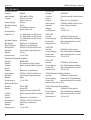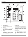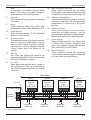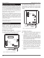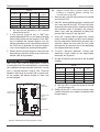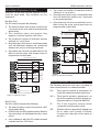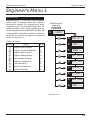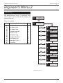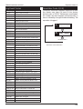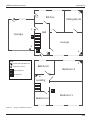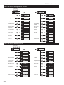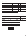
1
TS690R
Wireless Intruder Alarm
Control Panel
SYS OPEN
1
2
3
4
5
6
8
9
7
0
SYS OPEN
1
2
3
1
2
3
4
5
6
4
5
6
7
8
9
7
8
9
0
0
Installation & Programming
Manual (DRAFT)
TS690R Installation Manual
Contents
Overview
Introduction . . . . . . . . . . . . . . . . . . . . . . . . . 4
Control Panel . . . . . . . . . . . . . . . . . . . . . . . . 4
Jamming Detection . . . . . . . . . . . . . . . . . . . 4
Wireless Detectors. . . . . . . . . . . . . . . . . . . . . 4
502r Watch Pendant PA . . . . . . . . . . . . . . 4
509r Fire Detector . . . . . . . . . . . . . . . . . . . 4
515r Passive Infra Red. . . . . . . . . . . . . . . . 4
525r Remote Setting Device. . . . . . . . . . . 4
535r Universal Transmitter . . . . . . . . . . . . . 4
Remote Keypads . . . . . . . . . . . . . . . . . . . . . 4
8 Character Starburst (TS690.STAR) . . . . . . 5
Remote Arming Station (TS700.ARM). . . . . 5
System Architecture . . . . . . . . . . . . . . . . . . . 5
TS700 LEC . . . . . . . . . . . . . . . . . . . . . . . . . . . 5
Specifications . . . . . . . . . . . . . . . . . . . . . . . . 6
Control Panel . . . . . . . . . . . . . . . . . . . . . . 6
Starburst Remote Keypad. . . . . . . . . . . . . 6
Arming Station . . . . . . . . . . . . . . . . . . . . . 6
TS700 LEC . . . . . . . . . . . . . . . . . . . . . . . . . 6
502r PIR. . . . . . . . . . . . . . . . . . . . . . . . . . . 6
509r PIR. . . . . . . . . . . . . . . . . . . . . . . . . . . 6
515r PIR. . . . . . . . . . . . . . . . . . . . . . . . . . . 6
525r Remote Setting Device. . . . . . . . . . . 6
535r Universal Transmitter . . . . . . . . . . . . . 6
System Installation
Radio Site Survey . . . . . . . . . . . . . . . . . . . . . 7
Procedure for simple Installation. . . . . . . . 7
Procedure for Certified Installation . . . . . . 7
Control Panel Location. . . . . . . . . . . . . . . . . 7
Cable Routing . . . . . . . . . . . . . . . . . . . . . . . 7
Control Panel Assembly . . . . . . . . . . . . . . . . 8
Control Panel Installation . . . . . . . . . . . . . . . 9
Mains Connection . . . . . . . . . . . . . . . . . . . . 9
Battery Connection . . . . . . . . . . . . . . . . . . . 9
PCB Layout . . . . . . . . . . . . . . . . . . . . . . . . . . 10
Remote/LEC Network Wiring . . . . . . . . . . . . . 12
Remote Keypads . . . . . . . . . . . . . . . . . . . . . 12
TS790 Star Remote Keypad . . . . . . . . . . . 12
TS700 Remote Arming Station. . . . . . . . . . 12
Installation Procedure. . . . . . . . . . . . . . . . 12
TS700 LEC Installation . . . . . . . . . . . . . . . . . . 13
2
Hard Wired Detection Circuits . . . . . . . . . . . 14
Double Pole . . . . . . . . . . . . . . . . . . . . . . . 14
End Of Line . . . . . . . . . . . . . . . . . . . . . . . . 14
External Sounder Connections . . . . . . . . . . . 14
Auxiliary Tamper . . . . . . . . . . . . . . . . . . . . . . 15
Extension Loudspeakers . . . . . . . . . . . . . . . . 15
Installing a 515r PIR . . . . . . . . . . . . . . . . . . . 15
Siting the 515r PIR . . . . . . . . . . . . . . . . . . . 15
Installation. . . . . . . . . . . . . . . . . . . . . . . . . 16
Testing . . . . . . . . . . . . . . . . . . . . . . . . . . . 16
Walk Testing and Lockout . . . . . . . . . . . . . 16
525r Remote Setting Device. . . . . . . . . . . . . 17
Learning . . . . . . . . . . . . . . . . . . . . . . . . . . 17
Changing the Battery . . . . . . . . . . . . . . . . 17
Installing a 535r Universal Transmitter . . . . . . 17
Siting the 535r Universal Transmitter. . . . . . 17
Using the internal Reed Switch . . . . . . . . . 18
Installation. . . . . . . . . . . . . . . . . . . . . . . . . 18
Connecting External Door Contacts . . . . . 18
Testing . . . . . . . . . . . . . . . . . . . . . . . . . . . 18
Connecting a Printer . . . . . . . . . . . . . . . . . . 19
Using the CPA6 Printer . . . . . . . . . . . . . . . . 19
Using the DATAC / RS232 Printer . . . . . . . . 19
Programmable Outputs . . . . . . . . . . . . . . . . 19
Control Panel Outputs. . . . . . . . . . . . . . . . 19
Remote Keypads & TS700.LECs . . . . . . . . 19
Pre Power-Up Checks . . . . . . . . . . . . . . . . . . 20
Initial Power-Up . . . . . . . . . . . . . . . . . . . . . . . 20
Power-Up Checks . . . . . . . . . . . . . . . . . . . . . 20
NVM Defaults . . . . . . . . . . . . . . . . . . . . . . . . 21
Engineer’s Menu 1
Introduction . . . . . . . . . . . . . . . . . . . . . . . . . 23
Menu contents . . . . . . . . . . . . . . . . . . . . . 23
Panel Outputs [1.1]. . . . . . . . . . . . . . . . . . . . 24
Programmable Output Types . . . . . . . . . . . . 24
Program Circuits [1.4] . . . . . . . . . . . . . . . . . . 26
Circuit Types . . . . . . . . . . . . . . . . . . . . . . . 26
Circuit Attributes . . . . . . . . . . . . . . . . . . . . 27
System Timers [1.5] . . . . . . . . . . . . . . . . . . . . 28
Setting Modes [1.6]. . . . . . . . . . . . . . . . . . . . 30
Remote Reset Algorithm [1.8]. . . . . . . . . . . . 30
Configuration [1.9] . . . . . . . . . . . . . . . . . . . . 31
TS690R Installation Manual
Goto User Menu 1 [1.0] . . . . . . . . . . . . . . . . 32
Add/Cancel Devices [1.A] . . . . . . . . . . . . . . 33
Adding Devices . . . . . . . . . . . . . . . . . . . . 33
Removing Detectors. . . . . . . . . . . . . . . . . 33
Re-Map Keypad Circuits . . . . . . . . . . . . . . . 34
Engineer's Menu 2
Introduction . . . . . . . . . . . . . . . . . . . . . . . . . 35
Menu Contents. . . . . . . . . . . . . . . . . . . . . 35
View Circuits [2.1] . . . . . . . . . . . . . . . . . . . . . 36
Set System Time [2.2] . . . . . . . . . . . . . . . . . . 36
Set System Date [2.3] . . . . . . . . . . . . . . . . . . 36
Change Passcode [2.4] . . . . . . . . . . . . . . . . 37
Chime Circuits [2.5] . . . . . . . . . . . . . . . . . . . 37
Print System Log [2.7] . . . . . . . . . . . . . . . . . . 37
Configure Part Sets [2.8] . . . . . . . . . . . . . . . . 38
View System Log [2.9]. . . . . . . . . . . . . . . . . . 38
Log Event Codes . . . . . . . . . . . . . . . . . . . . . 39
Reset User Code 1 [2.0] . . . . . . . . . . . . . . . . 39
Circuit Text [2.B] . . . . . . . . . . . . . . . . . . . . . . 40
Appendices
Setup New Users . . . . . . . . . . . . . . . . . . . . . . 41
User Types . . . . . . . . . . . . . . . . . . . . . . . . . 41
Part-Set Application Example . . . . . . . . . . . . 42
Notes . . . . . . . . . . . . . . . . . . . . . . . . . . . . . . 44
Notes . . . . . . . . . . . . . . . . . . . . . . . . . . . . . . 45
Quick Reference Engineers Menus. . . . . . . . 46
Quick Reference User Menus . . . . . . . . . . . . 46
3
Overview
TS690R Installation Manual
Overview
Introduction
The TS690R wireless alarm control system has been
designed to suit small to medium installation sites.
The system can monitor 30 wireless zones and 8
conventional zones via remote keypads or LECs.
The TS690R is designed to meet the requirements
of BS6799 class "III" and complies with all current
NACOSS codes of practice for domestic and small
business audible ONLY intruder alarm systems. The
system can be certificated by approved installers
as a Wirefree "Class III" installation.
The radio operating frequency between the
control panel receiver and the detectors is
418MHz with a bandwidth of 200kHz. The radio
section is approved to MPT 1340.
Control Panel
The control panel is the controlling unit for the
system, it has a power supply and connections for
a standby battery. It has the following facilities:
l
On board keypad
l
8 character Starburst LCD display
l
Bell and strobe outputs
l
3 programmable outputs
l
Extension loudspeaker output
l
Printer output
l
All system program information and the 150
event log is stored in a removable non-volatile
memory (NVM)
l
10 user codes + engineer's code
l
2.1Ah battery capacity
Jamming Detection
The TS690R features a radio jamming detection
option which can be enabled or disabled (see
"System Configuration" on page 31. When
enabled the control panel monitors for other radio
signals on the same frequency used by the
detectors. If the control panel detects a
continuous signal for more than 30 seconds the
control panel will raise an alarm. In the unset state
4
the alarm causes the internal sounders to beep
every minute and the display shows "JAMMED". In
a full or part set state a full alarm is generated.
Wireless Detectors
The TS690R uses the Scantronic 500 series range of
wireless detectors. The following devices are
available:
502r Watch Pendant PA
The 502r watch pendant is designed for use as a
panic alarm for the TS690R. The 502r comprises a
plastic waterproof case that can either be worn on
a strap round the wrist, round the neck as a
pendant or clipped to a pocket.
509r Fire Detector
The 509r fire detector sends a signal to alarm
panel when it detects the presence of smoked.
515r Passive Infra Red
The 515r Passive Infra Red (PIR) is an indoor
detector which has a 10 metre range.
525r Remote Setting Device
The 525r remote setting device can be used to
set, unset and part set the alarm system. In
addition, pressing the "ARM" and "OFF" at the
same time will cause a panic alarm.
535r Universal Transmitter
The 535r universal transmitter sends a signal to
alarm panel when the associated magnet moves
away from the case, and sends a restore signal
when the magnet is re-aligned. If required, you
can wire external normally closed devices (e.g.
20mm flush contacts) to the 535r.
Remote Keypads
Up to 4 remote keypads can be connected to the
control panel. Each remote keypad has two hard
wired detection circuits and a single switched -ve
output. There are two types of remote keypads
that can be used:
TS690R Installation Manual
Overview
8 Character Starburst (TS690.STAR)
The TS790 star remote keypad has a backlit 8
character Starburst display (LCD) and a backlit
tactile rubber keypad.
TS700 LEC
The Local Expansion Card (LEC) provides two
programmable hard wired detection circuits and
one programmable output.
Remote Arming Station (TS700.ARM)
The Remote Arming Station only allows setting and
unsetting of the system. The unit has two indicator
LEDs, the “Power LED” and a programmable
“Function LED” (the “Function LED” may be
programmed as “Fault” or “Area Set” etc.).
System Architecture
Remote
Network
Printer
Speaker
TS690R
Aux 12V
Bell output
1 Output
1 Output
1 Output
1 Output
Remote
Keypad
or LEC
Remote
Keypad
or LEC
Remote
Keypad
or LEC
Remote
Keypad
or LEC
2 Zones
2 Zones
2 Zones
2 Zones
(DP / EOL)
(DP / EOL)
(DP / EOL)
(DP / EOL)
On board Keypad
and LCD display
Strobe output
Outputs 1- 3
Watch /
Pendant
( P/A )
502r
Fire
Detector
509r
Passive
Infra
Red
515r
Remote
Setting
Device
525r
Universal
Transmitter
535r
Up to 30 wireless detectors
Figure 1. TS690R System Architecture
5
Overview
TS690R Installation Manual
Specifications
Control Panel
Part No.:
Input Supply:
Current:
Power Supply:
Standby Battery:
Zones
remotes/LECs
Outputs 1-3:
Speaker Output:
Bell Trigger:
Strobe Trigger:
Dimensions:
Material:
Weight:
Environment:
TS700 LEC
TS690R
230V 10% 50Hz
120mA (normal)
300mA (alarm)
750mA
2.1Ah
30 wirefree devices
8 hard wired via
Part No.:
Current:
Zones:
Output:
Dimensions:
Material:
Weight:
Environment:
1 = Switched -ve @100mA
2 = Switched -ve @100mA
3 = Switched -ve @100mA
16 Ohms
Switched -ve @500mA
Switched -ve @500mA
205(W) x 205(H) x 64(D) mm
3mm white polycarbonate
1.4 Kg
-10 to 55 C
502r PIR
Starburst Remote Keypad
Part No.:
Display:
Current:
Zones:
Output:
Dimensions:
Material:
Weight:
Environment:
Current:
Zones:
Output:
Dimensions:
Material:
Weight:
Environment:
6
502rUK-00 (Scantronic)
Two AAA Alkaline batteries
Approximately 14 months
-10 to 55 C
509r PIR
Part No.:
Power Supply:
Power Life:
Environment:
509rUK-00 (Scantronic)
Two AAA Alkaline batteries
Approximately 14 months
-10 to 55 C
TS690.STAR
8 character Liquid Crystal
50mA (normal) 60mA (alarm)
2
Switched -ve @100mA
130(W) x 130(H) x 30(D) mm
3mm white Polycarbonate
280g
-10 to 55 C
515r PIR
TS700.ARM
Power LED
Programming function LED
30mA (normal) 40mA (alarm)
2
Switched -ve @100mA
130(W) x 130(H) x 30(D) mm
3mm Polycarbonate
280g
-10 to 55 C
535r Universal Transmitter
Arming Station
Part No.:
Display:
Part No.:
Power Supply:
Power Life:
Environment:
TS700.LEC
30mA (normal) 40mA (alarm)
2
Switched -ve @100mA
142(W) x 820(H) x 36(D) mm
3mm Polycarbonate
213g
-10 to 55 C
Part No.:
Power Supply:
Power Life:
Environment:
515rUK-00 (Scantronic)
Two AAA Alkaline batteries
Approximately 14 months
-10 to 55 C
525r Remote Setting Device
Part No.:
525rUK-00 (Scantronic)
Power Supply:
Duracell DL 1/3N (Alkaline)
Power Life:
Approximately 14 months
Environment:-10 to 55 C
Part No.:
Power Supply:
Power Life:
Environment:
535rUK-00 (Scantronic)
Two AAA Alkaline batteries
Approximately 14 months
-10 to 55 C
TS690R Installation Manual
System Installation
System Installation
Radio Site Survey
With a wirefree system we recommend that you
carry out radio tests as part of a site survey to
ensure that the control panel can receive the
radio signal from the detectors. If you cannot do
the tests during a survey, carry them out before
installation.
Procedure for simple Installation
1. Place the control panel in its planned location.
2. Power up the control panel.
3. Program the control panel to learn a detector.
Control Panel Location
The following considerations must be taken when
installing the control panel.
1. Positioned in a convenient location to connect
the mains supply.
2. Positioned within the protected area.
3. Positioned in a convenient location so that the
users can reach the control panel in order to
operate the system.
4. Ensure that there is a clear space around the
control panel to allow it to receive a good
radio signal.
4. Select the "Walk Test" option (see user guide).
Do NOT locate the panel
5. Test the reception by triggering the detector at
each planned location. If the control panel
generates a tone the detector is being
received.
5. Outside the area covered by the alarm
system.
Procedure for Certified Installation
You will need a 545r Radio Signal Strength meter
and a 546 Test Transmitter.
1. Switch the test transmitter on and place it at the
proposed site for the control panel. The
transmitter sends a pulsed signal, 10 seconds
on and 5 seconds off.
2. Switch the test meter into "Track" mode and
walk around the premises.
3. Check that the signal strength is between 5
and 9 at each proposed location for
detectors.
4. Move to a different location to improve the
signal strength if it is between 1 and 4. Make
sure the new location is suitable for the
detector.
5. Change the location of the test transmitter if
the signal strength is not greater than 4 for any
transmitter, make sure that the user agrees to
the new location for the control panel.
6. For certified systems note down the signal
strength for each detector location and keep
a record in the control panel and in the
installation file.
6. Near to ground level.
7. Close to or on large metal structures, for
example: water tanks, cars, fridges and
freezers.
8. Closer than 1 metre to mains wiring and metal
water or gas pipes.
9. Inside steel closures.
10. Next to high voltage electrical equipment, or
electronic equipment, particularly computers,
photocopiers or other radios.
Cable Routing
When installing cables, the following should be
noted:
+
Ensure that all Network and hard wired
detection circuit cables are kept clear of
mains supply cables, telephone cables,
R.F. cables and cables supplying bells or
sounders.
+
Mains power supply cables to the system
must be connected to an un-switched
fused spur that cannot be accidentally
switched off. The mains cable must enter
the housing via its own cable entry point.
7
System Installation
TS690R Installation Manual
Control Panel Assembly
1
2
3
9
4
5
8
6
-
+
Battery
2.1 Ah max.
7
Figure 2. TS690R Control Panel Layout
1
Mains cable entry
The main supply cable for the TS690R must
enter the control panel via this entry point.
2
Main PCB
The main Printed Circuit Board (PCB).
3
Display
A back lit 8 character Starburst LCD.
4
Loudspeaker
The internal sounder for the TS690R. It is
located underneath the main PCB.
5
Radio Module
Radio receiving module. DO NOT adjust the
trimmer on the module.
6
Aerial
Radio receving aerial. The aerial must
positioned as shown when refitting the PCB.
8
7
Standby Battery
A 2.1 Amp Hour (Ah) battery must be fitted
inside the TS690R in order to maintain the
system in the event of a mains power failure.
8
Mains Transformer
The mains transformer which transforms the
incoming mains supply down to 18V a.c.
9
Mains Fused Terminal Block
The mains connection terminals for the
TS690R. The terminal block is fitted with a
200mA fuse.
TS690R Installation Manual
Control Panel Installation
Proceed as follows:
1. Remove the screw from the top of the control
panel and lift away the front cover.
2. Ensure that there is no battery in the housing,
then remove the Printed Circuit Board (PCB) as
follows:
(a) Disconnect the AC leads from the
transformer and disconnect the internal
loudspeaker from the terminal block
connections.
System Installation
Mains Connection
The mains supply is connected to a 3 way "Euro
Type" fused terminal block, which is fitted with a
200mA fuse. All electrical connections should be
carried out by a qualified electrician and must
comply with the current IEE regulations.
+
To comply with European regulations the
supply should be fed from a readily
accessible disconnect device, e.g.
un-switched fused spur fitted.
+
When making mains connections it should
be ensured that if the cable slips in such a
way as to place a strain on the conductors,
the protective earthing conductor will be
the last to take the strain.
(b) Pull down the plastic clip at the bottom right
hand corner of the PCB and gently lift the
PCB forward.
(c) Repeat with the plastic clip at the bottom
left hand corner of the PCB.
(d) The bottom of the PCB will then swing
forward and the whole PCB will come away
from the back box.
(e) Store the PCB in a safe place.
3. Hold the control panel back box in the required
position (keyhole to the top) and mark the
centre of the keyhole position. Remove the
back box, drill and plug the hole.
4. Screw a No 10 screw into the plugged hole.
Re-position the back box and mark the
remaining two securing holes. Remove the
back box, drill and plug the holes.
5. Re-position the back box and pass all cables
into the back box via the appropriate cable
entries.
FUSE 200mA
L
E
To transformer
N
Figure 3. Mains Supply Connections
Battery Connection
A 2.1Ah battery must be fitted to the system to
allow it to function during a mains fail condition.
The TS690R is equipped with a “Battery Protection”
circuit so that if a battery is accidentally reverse
connected or its voltage is below 4V. To clear the
fault simply reconnect or replace the battery as
appropriate.
6. Secure the back box using not less than 30mm
x No 10 screws through the three securing
holes.
7. Re-fit the PCB assembly by aligning the top of
the PCB into the 2 supports in the top of the
housing ensuring that the edges of the board
sit between the 2 flanges and that aerial is
positioned as shown in figure 2. Push the
bottom of the PCB until it clicks in place.
8. Re-connect the AC leads to the transformer.
9. If a remote keypad is being fitted to the system,
refer to page 12.
9
System Installation
TS690R Installation Manual
PCB Layout
1
2
3
4
DETECTOR
LEARN
PRINTER
A B C D E
REMOTE NETWORK
18
JP1
1- 2- 3OUTPUTS
17
5
FACTORY
RESET
6
AUX
TAMP
16
+
- SPK H/O H/O TR- STB TRG
- AUX 12V +
+
BELL
15
14
13
SPEAKER
VOL
1
2
3
4
5
6
7
8
9
ENT
0
ESC
A
B
C
7
8
VR1
A.C.
12
11
10
9
Figure 4. Mains Supply Connections
1
Auxiliary / Remote Fuse
This 1 Amp fuse protects the supply to the
remote network and auxiliary devices.
2
Printer Port
This 6-pin plug is used for connecting to
either a CPA6.P printer or a standard RS232
printer via the MPA/DCI printer adapter.
3
Display
A back lit 8 character Starburst LCD.
4
Learn Sensor
When learning new devices you must hold
the device so that the activity LED on the
device aligns with the learn sensor.
10
5
Factory Reset
If these pins are shorted during power-up all
system parameters are reset to their factory
default settings. If the engineer’s passcode
is lost or forgotten it can be reset to 1234
without losing any other program data by
shorting these pins whilst the system is
powered.
6
Tamper Switch
The tamper switch provides the tamper
protection for the main control panel, so
that if the cover is removed an alarm is
generated.
TS690R Installation Manual
System Installation
7
NVM
A removable non-volatile memory (NVM)
device that stores all system program
parameters and the 150 log events.
14
Bell Connection Terminals
These terminals provide the necessary
connections to the external sounder or bell.
Full details of connections are on page 14.
8
Keypad
A back lit rubber key mat used for operating
the system.
15
9
Aerial
Radio receiving aerial. The aerial must
positioned as shown when refitting the PCB.
Extension Loudspeaker
This terminal provides an output to a 16 Ohm
extension loudspeaker. The other side of the
loudspeaker is connected to the [H/O-]
terminal.
16
Auxiliary Tamper
These two terminals provide tamper
protection to auxiliary devices, such as
power supplies, extension loudspeakers etc.
If they are not used they must be linked out.
17
Panel Outputs
These are three switched -ve outputs rated
at 100mA. Each output is programmable
and can be used to trigger other devices
such as the SD1+ speech dialler.
18
Remote Network
These terminals provide the necessary
connections to remote keypads. Full details
of connections are shown below.
10
Radio Module
Radio receiving module. DO NOT adjust the
trimmer on the module.
11
Speaker Volume
This adjust the volume of the internal sounder
and any extension loudspeakers. Only the
volume of the advisory tones such as entry,
exit and chime may be adjusted using this
control. Alarm tones are always at full
volume.
12
Bell Fuse
This 1 Amp fuse protects the supply to the
external sounder/bell. The fuse is in-line with
the [H/O+] terminal connection.
13
AC Input
These flying leads provide the ac supply to
the control panel. They are connected to
the mains transformer and are not polarity
conscious.
100m (Max.)
Spare Core
I/D=1
I/D=2
I/D=3
I/D=4
Remote
Keypad
or LEC
Remote
Keypad
or LEC
Remote
Keypad
or LEC
Remote
Keypad
or LEC
A B CD E
Control Panel
A B CD E
A B CD E
A B CD E
A
B
Remote
Network C
D
E
+
Power for
detectors
+
Power for
detectors
+
Power for
detectors
+
Power for
detectors
Figure 5. TS690R Main PCB
11
System Installation
TS690R Installation Manual
TS700 Remote Arming Station
Remote/LEC Network Wiring
The Remote Network connections are used for
connecting either remote keypads or LECs. Each
device has 5 connection terminals and therefore
a 6 core cable is required for interconnection. It is
recommended that the spare core is doubled up
with the [B] connection as this will help reduce
voltage drop on long cable runs.
The TS700 remote arming station only has two
indicator LED's, a power LED and a programmable
function LED which follows the programmable
output.
Devices can be individually connected back to
the control panel (star connection) or looped
together (daisy-chain connection). Which ever
method of connection is used the distance to the
furthest device from the control panel must not
exceed 100 metres.
2 detection
circuits
Tamper
Switch
REMOTE
I/D
1
2
3
4
ENG
I/D
Selector
DISABLED
Power for detectors are provided by the [A] and [B]
terminals, see figure 5.
'ENT' KEY
A B C D E O/P-
DISABLED
Remote Keypads
Two types of remote keypads can be used on the
system, however, only the TS790 Star remote
keypad can be used for programming. Any
combination of remote keypad can be used on
the same system if desired.
TS790 Star Remote Keypad
The TS790 remote keypad has a 8 character
backlit Starburst Liquid Crystal Display (LCD).
LCD Module
I/D
Selector
REMOTE
I/D
1
2
3
4
ENG
WARD SOUNDER
CONTROL
2 Detection
circuits
'ENT'
Key
Disable
Tamper
Switch
A B C D E O/P-
= Disabled
Remote network
connections
Programmable output
switched -ve
@ 100mA
Figure 6. TS690R Remote Network Wiring
12
Remote network
connections
Programmable output
switched -ve
@100mA
Figure 7. TS790 Star Remote Keypad Layout
Installation Procedure.
+
Always ensure that all power (mains and
battery) is removed before making any
connections to the remote keypad.
1. Separate the cover and base by using a
screwdriver to push 2 of the clips (top or
bottom) inward from the base indents, then lift
the cover assembly, noting that the PCB is fixed
to the under side of the cover.
2. Hold the base in position (keyhole to the top)
and mark the three securing holes, drill and
plug the wall as required. Pass all the cables
into the base via the cable entry points as
appropriate and secure the base to the wall.
3. Connect “Remote Network” and detection
circuit cables to the appropriate terminals.
4. Set the I/D selector jumper link to the required
position:
TS690R Installation Manual
System Installation
TS690R
I/D Selector
Circuit A
Circuit B
Panel
Output
1
31
32
5
2
33
34
6
3
35
36
7
4
37
38
8
ENG/NULL
N/A
N/A
N/A
l
No two remote keypads or LECs should
have the same I/D.
5. If the remote keypad has a "ENT" key
enabled/disable link it can be used to limit the
functionality of the remote keypad. If the "ENT"
key is enabled the remote keypad can be
used to set/unset and access all user menus. If
the "ENT" key is disabled the remote keypad
can only be used to set and unset the system.
+
Always ensure that all power (mains and
battery) is removed before making any
connections to the LEC.
1. Remove the cover from the base and carefully
remove the PCB.
2. If the LEC is being fitted inside the control panel
you may remove the LEC PCB from its base
and secure it to base of the control panel using
self adhesive feet. If required, the tamper
switch may also be disabled by fitting the
jumper link across JP2, see Figure 8.
3. If the LEC is being fitted outside the control
panel, hold the base in position and mark the
two securing holes. Drill and plug the wall, then
pass all cables into the base via the cable
entry points. Secure the base to the wall using
the appropriate fixing screws.
6. Finally clip the remote keypad cover onto the
base being careful not to trap any cables or to
obstruct the tamper switch.
4. Connect “Remote Network” cables and
detection circuit cables to the appropriate
terminals, see Figure 8.
TS700 LEC Installation
5. Set the I/D selector jumper link to the required
position:
The TS700 LEC (Local Expansion Card) is
connected to the “Remote Network” and provides
two additional programmable detection circuits
and a programmable output. The “Remote
Network” may have up to three LECs connected,
as the system will always require at least one
remote keypad.
CABLE ENTRY
E D C B A
CCT B
ZB TB
O/P
CCT A
ZA TA
Programmable
detection circuits
Network
connections
LEC I/D
12 34
Programmable
output
switched -ve
@100mA
TS690R
I/D Selector
Circuit A
Circuit B
Panel
Output
1
31
32
5
2
33
34
6
3
35
36
7
4
37
38
8
ENG/NULL
N/A
N/A
N/A
l
No two LECs or remote keypads should
have the same I/D.
6. Finally clip the LEC cover onto the base being
careful not to trap any cables or to obstruct the
tamper switch.
I/D selector
JP2
TAMPER = JP2 NOT FITTED
NO TAMPER = JP2 FITTED
Tamper switch
CABLE ENTRY
Fit jumper-link to
disable tamper switch
Figure 8. TS700 Remote Arming Keypad Layout
13
System Installation
TS690R Installation Manual
Hard Wired Detection Circuits
Detection circuits from remote keypads or LECs
must be hard wired. Two methods can be
employed:
Double Pole
The DP method requires the following:
l
l
The maximum number of detection devices
allowed in a circuit is ten.
l
Normally open devices such as pressure pads
and exit terminator buttons are connected
across outer terminals
l
If the detection circuit is not used links can be
fitted across the zone and tamper loops or
programmed as Not Used.
The detector alarm and tamper contacts are
connected to the zone and tamper terminals
respectively.
l
The combined alarm and tamper loop
resistance must be less than 100 Ohms.
l
The maximum number of detection devices
allowed in a circuit is ten.
l
Normally open devices such as pressure pads
and exit terminator buttons are connected
between the zone and tamper terminals.
l
If the detection circuit is not used links can be
fitted across the zone and tamper loops or
programmed as Not Used.
500 meters or 100 Ohms
4K7 = Yellow, Violet, Red
2K2 = Red, Red, Red
4K7
Alarm
Tamper
4K7
500 meters or 100 Ohms
4K7
Alarm
Alarm
Tamper
Tamper
2K2
Max. 10 devices per circuit
Alarm
2K2
Tamper
Alarm
2K2
Wiring N.O. devices (Exit Terminators)
Alarm
Figure 10. Double Pole Wiring
Tamper
Tamper
Max. 10 devices per circuit
External Sounder Connections
The following terminals have been provided to
allow connections to an external sounder:
H/O Wiring N.O. devices (Exit Terminators)
Figure 9. TS700 LEC Layout
End Of Line
The EOL method requires the following:
l
The detector alarm contacts must have a 4K7
shunt resistor fitted.
l
A 2K2 End of Line (EOL) resistor must be fitted at
the point in the circuit furthest from the control
panel.
l
Loop resistance with the EOL resistor shorted
must be less than 100 Ohms.
14
This is used to provide a permanent -ve
hold off to external sounders, strobes etc.
H/O + This is used to provide a permanent +ve
hold off to external sounders, strobes etc.
It is protected by a 1 Amp fuse (Bell 12V).
TR -
This is the negative tamper return
connection from the siren or bell.
STB -
This is the strobe output which will switch to
0V on alarm and is rated at 500mA.
Connect the other side of the strobe to
the H/O +.
TS690R Installation Manual
TRG -
System Installation
This is the bell trigger output which will
switch to 0V on alarm and is rated at
500mA. This output can be programmed
for SAB or SCB operation, as follows:
SAB: TRG - will switch to 0V on alarm and
will provide a maximum of 500mA.
SCB: TRG - will provide a negative hold
off (500mA), which is removed on alarm.
Installing a 515r PIR
Typical
External Sounder
Control
Panel
12V +
0V
Tamper In
H/O +
H/O TR STB TRG -
Tamper Out
Strobe +ve
Strobe -ve
Trigger -ve
Figure 11. End of Line Wiring
Activity LED
The 515r Passive infra Red (PIR) is an indoor
detector designed to work with the TS690R control
panel. The detector has a fan shaped sensitive
area approximately 10 metres in radius.
Fixing hole cutouts
Tamper
Battery case
Auxiliary Tamper
These two terminals provide tamper protection to
auxiliary devices such as power supplies,
extension loudspeakers etc. If they are not used
they must be linked out.
+
+
Extension Loudspeakers
Up to two extension loudspeakers can be
connected across the [SPK+] and [H/O-] terminals
on the control panel PCB. The volume for the
loudspeaker is controlled by VR1 “Speaker
Volume”.
Back
Body
Siting the 515r PIR
You can mount the unit either flat against the wall,
or in a corner. The area covered by the detector is
shown below:
SPK+
H/O 1 x 16 Ohm Loudspeaker
SPK+
H/O -
10m
2 x 16 Ohm Loudspeakers
Figure 12. External Sounder Connections
10m
2m
15
System Installation
Do mount the unit
l
Between 2 and 2.5 metres high for the best
general coverage in an average room.
Do NOT mount the unit
l
Facing a fire, boiler or window.
l
Over a radiator.
l
Near the floor.
l
Close to or on large metal structures.
l
Closer than one metre to mains wiring and
metal water or gas pipes.
l
Inside steel closures.
l
Next to electronic equipment, particularly
computers, photocopies or other radio
equipment.
l
Closer than 3 cm to a ceiling (to allow space
for dismounting the unit in the future).
TS690R Installation Manual
3. Make sure the control panel receives the
alarm from each detector.
4. Choose another site for the detector if the
panel does not receive the signal.
5. Wait 30 seconds with no movement in front of
the detector before triggering it again.
6. Press [ESC] twice when you have finished
testing, to put the control panel back in the
open mode.
Walk Testing and Lockout
In normal use the 515r uses a three minute lockout
timer in order to extend battery life. The lockout
timer operates as follows:
1. The unit detects movement, signals the control
panel, and starts the lockout timer.
Installation
2. If the unit detects movement while the lockout
timer is running, then it restarts the lockout timer
but DOES NOT signal the control panel.
1. Open the detector by inserting a small flat
bladed screwdriver in the slot at the bottom of
the case.
3. When the lockout timer expires the unit signals
the control panel the next time it detects
movement.
2. Install two "AAA" size alkaline batteries (not
supplied). Do not use rechargeable (Nickel
Cadmium) batteries, because they are 1.2V
and not 1.5V.
If you want to test a 515r PIR in normal uses you
must wait at least 3 minutes between activations.
To make testing easier the detector changes the
lockout period to 30 seconds for the first 30
minutes after you put the batteries in or after you
trigger its tamper.
3. Learn the detector (see "Adding Devices" on
page 33).
4. Mount the detector back box in its required
position using two 16mm countersunk head
screws.
5. Clip the body of the detector to the back box.
Testing
1. Put the TS690R control panel into walk test
mode (user code + [ENT] + [2]).
2. Open and close the tamper for each PIR, this
will put the detector in test mode.
+
16
After opening and closing the tamper,
the detector remains in test mode for 30
minutes. In this mode the detector has a
30 seconds lockout time. At the end of
the 30 minutes the detector reverts to
normal mode, with a 3 minute lockout
time.
TS690R Installation Manual
System Installation
525r Remote Setting Device
Installing a 535r Universal Transmitter
Activity LED
ARM
PANIC
NIGHT
Part set button
OFF
5
The 525r remote setting device can be used to
set, part set (part set A only) and unset the alarm
system. In addition, pressing the "ARM" and "OFF"
at the same time will cause a panic alarm. The
525r is assigned as a detection circuit.
Learning
See "Adding Devices" on page 33.
Changing the Battery
The battery used in the 525r is a Duracell DL 1/3N or
CR 1/3N or K58L (Alkaline). The battery can be
obtained from normal high street stockists.
1. Undo the screw holding down the battery
compartment cover.
2. Slide back the cover.
3. Replace the battery (make sure the battery
polarity is correct).
4. Replace the cover and tighten the screw.
Activity LED
The 535r universal transmitter is designed to work
with the TS690R control panel. The transmitter
signals an alarm when the associated magnet
moves away from the case, and sends a restore
signal when the magnet is re-aligned.
Terminal
Block
Internal Reed
Shunt Link
Internal
Reed
Fixing
Hole
+
Tamper
Bar
Battery
Case
Tamper
+
Fixing
Hole
Back
Body
Siting the 535r Universal Transmitter
Where possible, mount the unit close to the top of
the non-moving frame of a door or window, and
the magnet on the moving part. If the frame is not
wide enough, mount the magnet on the frame
and the unit on the moving part.
-ve Terminal
Battery
+ve Terminal
17
System Installation
Do
l
Make sure there is less than 10mm between
the magnet and transmitter body with the
door or window closed.
TS690R Installation Manual
4. Mount the transmitter back box in its required
position using two type "C" 15mm domehead
screws.
5. Make sure the back is flush against the surface
and pushes the tamper bar in far enough to
activate the tamper switch.
6. Fit the body of the transmitter to the back box.
Connecting External Door Contacts
l
Make sure the arrow on the magnet aligns with
the mark moulded into the side of the case
with the door/ window closed.
Do NOT mount the unit
On the hinged edge of the door..
l
Near the floor.
l
Close to or on large metal structures.
l
Closer than one metre to mains wiring and
metal water or gas pipes.
l
Inside steel closures.
l
Next to electronic equipment, particularly
computers, photocopies or other radio
equipment.
Using the internal Reed Switch
If you plan to use the internal reed switch the YOU
MUST CUT THE INTERNAL REED SHUNT LINK. However,
if at a later date you wish to connect hard wired
contacts you must re-solder the link.
Installation
1. Open the transmitter by inserting a small flat
bladed screwdriver in the slot at the bottom of
the case.
2. Install two "AAA" size alkaline batteries (not
supplied). Do not use rechargeable (Nickel
Cadmium) batteries, because they are 1.2V
and not 1.5V.
3. Learn the detector (see "Adding Devices" on
page 33).
18
1. Remove the wire links from the terminal
connector.
2. Connect the normally closed contacts as
shown:
Tamper
circuit
3
4
5
6
l
You can wire external normally closed devices to
the 535r universal transmitter. You can connect
several contacts in series, but the control panel will
treat them all as one zone. Do not use more than
10 metres total cable length from the 535r to the
last external contact.
Alarm
circuit
3. Make sure the internal reed shunt link is intact.
DO NOT CUT.
If you remove the external contacts at a later
date, make sure you replace the wire links on the
alarm and tamper terminals.
Testing
1. Put the TS690R control panel into walk test
mode (user code + [ENT] + [2]).
2. Hold The detector in place.
3. Trigger the tamper.
4. Make sure the control panel receives an
alarm.
5. Choose another site for the detector if the
panel does not receive the signal.
6. Press [ESC] twice when you have finished
testing, to put the control panel back in the
open mode.
TS690R Installation Manual
System Installation
Connecting a Printer
The TS690R supports two type of printers, the CPA6
printer (no longer available) and any standard
RS232 printer. When using an RS232 printer a
DCI/MPA printer adapter will be required. Menvier
Security supply a DATAC printer kit which consists of
a portable RS232 printer, charger unit and
DCI/MPA adapter.
R
POWE
PAPER
FEED
IN
DATA
Connect to JP1
PRINTER
CPA6
P
CPA6 Printer
Programmable Outputs
The TS690R has many programmable outputs
which can be used to drive relays, LED’s etc. Each
output can be programmed for a different
function, see "Programmable Output Types" on
page 24.
Control Panel Outputs
The control panel has three programmable
outputs:
[1-]
Switched -ve output rated at 100mA.
[2-]
Switched -ve output rated at 100mA.
[3-]
Switched -ve output rated at 100mA.
Remote Keypads & TS700.LECs
Each remote keypad and TS700 LEC has one
programmable output:
MPA
or DCI
RS232 Data
Switched -ve output rated at 100mA.
1
Connect to JP1
PRINTER
[O/P]
DATAC or RS232 printer
Figure 13. Printer Connections
Aux 12 V
Using the CPA6 Printer
1. Plug the CPA6 printer directly on to the PRINTER
plug (JP1) on the main control panel PCB.
2. The printer will printout a header, when finished
the system event log can be printed.
Diode (IN418)
-ve O/P
Relay
(Programmed as Alarm / Bell / etc)
Aux 12V
1K0 Ohm Resistor
3. When finished unplug the printer.
Using the DATAC / RS232 Printer
1. Plug the DCI/MPA on to the PRINTER plug (JP1)
on the main control panel PCB.
2. Plug the other end of the DCI/MPA into the
DATAC or RS232 printer.
Relay available from
RS components
P/No. 346-946.
Capable of switching
mains voltages
LED (Light Emiting Diode)
-Ve O/P
Aux 12V
12V Buzzer
RS Part No. 245-051
-Ve O/P
3. In order for the printer to work correctly ensure
the printer is set to the following:
Baud rate = 4800
Parity
= None
Stop bits
=2
Data bits
=8
DTR
= Normal
4. When set-up correctly the system event log can
be printed.
Figure 14. Output Examples
5. When finished unplug the MPA/DCI.
19
System Installation
Pre Power-Up Checks
Once the system is installed, but prior to
powering-up, give the system one final check to
ensure that:
1. The wiring conforms to the requirements
de t a il e d in t hi s m an ua l a n d t h at a ll
interconnections are correct (A to A, B to B
etc.).
2. All system cables are kept clear of mains
supply cables, telephone cables and R.F.
cables. It is recommended that cable ties be
used to keep cables separated.
3. Verify that maximum cable lengths and
resistance's are not exceeded.
4. Mains power supply cables to the system are
connected to an un-switched fused spur.
Initial Power-Up
To power the system for the first time:
1. Place a small screwdriver blade between the
pins on the control panel PCB, marked
“FACTORY RESET”. This will ensure the factory
default parameters are set, see page 21.
2. Switch on the 240V mains supply and remove
the screwdriver blade from the factory restarts
pins.
3. Check that the control panel and remote
keypads show “LID TAMP”. The internal sounder
and remote keypad sounders will operate.
4. Enter the engineers passcode (default 1234) to
silence the sounders.
5. Connect the standby battery.
6. Enter the engineers passcode (default 1234) to
select engineer's menu 1. Once you have
completed the “Power-up Checks” you can
continue to program the system.
20
TS690R Installation Manual
Power-Up Checks
When the initial power-up checks have been
completed, check the following:
1. Switch off the 240V mains supply and measure
the DC voltage at each remote keypad and
ensure the voltage is greater than 11V whilst
the system is powered from its standby battery.
2. Switch on the 240V mains supply and measure
the DC voltage between the mains earth
connection and AUX +12V. Then measure the
DC voltage between the mains earth
connection and AUX 0V. In both cases the
measurement should be 1V or less. If the
voltage is greater than 1V, the system has an
“Earth Fault” and all cables should be checked
for isolation to Earth.
TS690R Installation Manual
System Installation
NVM Defaults
Section
User Codes
Panel
Outputs
Circuits
System Timers
Option
Default
User 00 Engineer
1234
User 01 Master
5678
User 02 - 10
Not Used
Panel Output 1
Walk Test
Panel Output 2
Courtesy Light
Panel Output 3
Section
Option
Default
Full Set
Final Exit Setting
Part Set A
Timed Exit
Part Set B
Timed Exit
Part Set C
Timed Exit
Algorithm
004
SW12V
00 Bell is an SAB
Yes
Panel Output 5
Code Accepted
01 User 1 Limited
No
Panel Output 6
Code Accepted
02 Fire Signals All
Yes
Panel Output 7
Code Accepted
03 Silent 24hr Circuits
No
Panel Output 8
Code Accepted
04 Enable Duress
No
Circuits 01 - 38
Not Used
05 Invert Abort
No
00 2nd Alarm Time
005 seconds
06 Monitor Polling Sig
No
01 No of Re-arms
003
07 User Reset
No
02 Settle Time
005 seconds
03 Part Set Coms Dly
030 seconds
04 Exit Time
Setting
Modes
Rem Reset
Configuration
08 Fob unset with entry Yes
09 Passcode + ENT
No
030 seconds
10 Loud Chime Tones
Yes
05 Entry Time
015 seconds
11 Do Battery Test
No
06 Bell Duration
020 minutes
12 Final Exit is Night
No
07 Bell Delay
000 minutes
13 Mimic Alms & Flts
No
08 D-Knock Delay
008 seconds
14 Invert panel outputs No
09 Test Time
014 days
15 Set with AC off
No
10 Second Entry
015 seconds
16 Tampers user reset
No
11 Abort Delay
180 seconds
17 Enable jamming
Yes
12 Monitor Duration
010 seconds
13 Part Set Bell Delay
030 seconds
14 Courtesy Duration
060 seconds
15 AC Off Delay
000
21
System Installation
22
TS690R Installation Manual
TS690R Installation Manual
Engineer’s Menu 1
Engineer’s Menu 1
Introduction
Engineers menu 1 is the first of two engineers
menus, which is selected when the engineer’s
passcode is entered. The engineer may leave
“Engineer menu 1" by pressing the [ESC] key. The
system will return to the unset condition but the
remote keypads will show ”ENGINEER ON SITE". This
message will be cleared the next time a valid user
passcode is entered or by exiting the engineer's
mode via user menu 1.
Enter Engineer's
Passcode
1 2 3 4
E / MENU 1
1
PAN OP ?
4
CCT? --
5
TIMER --
6
SET MOD?
8
ALG
9
CONFIG --
0
U / MENU 1
A
ADD / CANX
C
MAP? --
Menu contents
Hot key
Option
Page
1
Program Panel Outputs
24
4
Program Circuits & Attributes
26
5
Program System Timers
28
6
Program Setting Modes
30
8
Remote Reset Number
30
9
Program Configuration
31
0
Goto User Menu 1
32
A
Add/Cancel Detectors
33
C
Re-Map Detectors
34
004
Engineers Menu 1
23
Engineer’s Menu 1
TS690R Installation Manual
Panel Outputs [1.1]
Outputs 1 - 3 on the control panel and remote
keypad outputs 5 - 8 can be programmed to any
of the output types shown on pages 24 to 26. In
addition, all panel outputs can be inverted, see
“Configuration option 14” on page 32.
E / MENU 1
1
PANEL Enter output No. 1 - 8
e.g. 1
004
Type No.
Enter new output type
e.g. 021
021
Panel Outputs Flowchart
Programmable Output Types
No
Type/Description
000 Bell On
Activates when the main Bell trigger is on and
deactivates at the end of the Bell Duration
time or when the alarm is cancelled by the
user.
001 Strobe On
Activates when the Strobe trigger is on, and
deactivates when the alarm is cancelled by
the user.
002 Switch 12V
Activates when the system is set and
deactivates when an alarm occurs or the
system is unset. This output is normally used for
latching detectors.
003 Detector Reset
Normally active at all times and deactivates
for 3 seconds when a valid passcode is
entered prior to setting the system. This output
is normally used for detector that required
power to be removed in order to reset them,
e.g., smoke detectors.
004 Walk Test
Activates when the "Walk Test" option is
selected and deactivates when the "Walk Test"
option is finished.
005 Alarm
Activates when an intruder alarm is detected
and deactivates when the alarm is reset or
aborted.
006 P.A.
Activates when a PA alarm is detected and
deactivates when the alarm is reset.
007 Fire
Activates when a Fire alarm is detected and
deactivates when the alarm is reset.
008 System Set
Ac t i va t es wh e n a n y w ar d i s s et a n d
deactivates when the system is fully unset.
009 Code Accepted
Activates for 10 seconds following entry of any
valid passcode.
010 24 Hour
Activates when a 24Hr alarm is detected and
deactivates when the alarm is reset.
24
TS690R Installation Manual
No
Type/Description
011 Second Alarm
Activates when a different detector causes an
alarm and remains active for the duration of
the "2nd Alarm Time". This output is normally
used for an ALARM CONFIRMATION signal.
012 Courtesy Light
Activates during entry and when any remote
keypad is used. The duration of this output is
controlled by the setting of the "COURTESY
DUR" timer.
013 Engineer On Site
Activates when the engineer’s passcode is
entered and deactivates when a user
passcode is entered.
Engineer’s Menu 1
No
Type/Description
024 Test Fail
Activates when a circuit fails test,, deactivates
when reset by the engineer.
025 First Knock
Activates when a double knock circuit is
activated for the first time. Deactivates when
the circuit is activated for the second time or
when the system is reset.
026 Abort
Activates for 5 seconds after an alarm is
aborted by the user. The period in which the
alarm may be aborted is set by the "Abort
Delay" see System Timers.
014 Circuits Omitted
Activates when any circuit is omitted and
deactivates when all circuits are reinstated.
027 Timed Output
Activates when a "Monitored" circuit is
triggered and remains active for the duration
of the "Monitor Delay" see System Timers.
015 Auxiliary
Activates when an Auxiliary alarm is detected
and deactivates when the alarm is reset.
028 Chime Mimic
Activates for 2 seconds when a circuit that is
programmed as "chime" is activated.
016 Part Set C Selected
Activates when "Part Set C" is selected.
Deactivates when the system is unset.
029 2nd Entry
Activates when the second entry timer is
started and deactivates when the second
entry timer expires.
017 Part Set B Selected
Activates when "Part Set B" is selected.
Deactivates when the system is unset.
018 Part Set A Selected
Activates when "Part Set A" is selected.
Deactivates when the system is unset.
019 Full Set Selected
Activates when "Full Set" is selected.
Deactivates when the system is unset.
020 Tamper Fault
Activates when a Tamper alarm is detected
and deactivates when the alarm is reset.
021 Signal Jammed
Activates when the control panel detects a
continuous radio signal for 30 seconds on the
same frequency used by the detectors.
Deactivates when the signal is removed.
022 Mains Off
Activates when mains power is removed and
deactivates when the mains power is restored.
023 Exit / Entry
Activates when the panel is in the exit or entry
mode.
030 Entry
Activates when the panel is in the entry mode.
031 Exit
Activates when the panel is in the exit mode.
032 Duress Alarm
Activates when a duress passcode is entered
and deactivates when the duress alarm is
reset.
033 System Part Set
Activates when the system is part set fails to set
and deactivates when the system is fully set or
unset.
034 Battery Fault
Activates when a battery fault occurs and
deactivates when the battery fault is cleared.
035 Set Fail
Activates when the system fails to set and
deactivates when the set fail condition is reset
by the user.
036 System Open
Activates when the system is unset,,
deactivates when the system is fully set or
part-set.
25
Engineer’s Menu 1
No
Type/Description
037 24hr cct Omitted
Activates when one or more 24 Hour circuits
are omitted.
038 Sounder Control
Normally used as the 0V connection for an
extension loudspeaker so that only system
alarm tones are generated.
039 Call Engineer
Activates when the system requires an
"Engineer Reset", deactivates when the
system is reset by the engineer or "Remote
Reset".
040 General Fault
Activates during battery fault or when the
s ys te m is pre ve nted from bein g s et .
Deactivates when all faults are cleared.
041 Battery Test
Activates for 1 minute on the hour every hour.
This output is used to test the battery in remote
PSU using a 519FM monitor PCB).
042 Fob Active
Activates when the 525r remote setting device
is used.
043 System Full Set
Activates when all areas within the system are
set and deactivates when any area is unset.
100 - 137 Circuit Mimic
Will mimic (active when circuit is active) circuits
01 to 38 respectively.
200 - 237 Circuit Alarms
Active when a circuit causes an alarm, for
circuits 01 to 38 respectively.
TS690R Installation Manual
Program Circuits [1.4]
The TS690R can monitor up to 38 detection
circuits. Each circuit must be programmed in
order for the system to respond correctly.
Circuit Types
The circuit type defines how the circuit will respond
when it is triggered. The following circuit types are
available:
0 Not Used
A circuit that will never generate any alarm.
1 Night
A circuit that will generate a full alarm when the
system is set.
2 24hr
A circuit which is monitored at all times. When
triggered in the unset condition a local alarm is
generated and when triggered in the set
condition a full alarm is generated.
3 PA Silent
A circuit which is monitored at all times. When
triggered it will activate any outputs that are
programmed as P.A.
4 PA Audible
A circuit which is monitored at all times. When
triggered it will activate any outputs that are
programmed as P.A. and generate a full
alarm condition.
5 Fire
A circuit that is normally connected to a smoke
detector. When triggered it will generate a fire
tone on the internal sounders, the external
sounders are pulsed for the bell duration and
any outputs programmed as fire will be
activated.
6 Auxiliary
A circuit which is monitored at all times. When
triggered it will activate any outputs
programmed as Auxiliary.
7 Final Exit
This must be the first detector or door contact
that is triggered when entering the protected
area. When the setting mode for the system is
programmed for Final Exit setting, opening
and closing of this circuit during the exit
procedure will cause the system to set. Once
set, activation of this circuit will start the entry
timer.
26
TS690R Installation Manual
8 Exit Terminator
A circuit that is normally connected to a push
button outside the protected premises, which
can be used to finally set the system or area.
9 Keypoint
A circuit that may be connected to a keyswitch
to allow setting and/or part-setting of the
system. The keypoint circuit can only be used
with the standard hard-wired circuits.
The Keypoint circuit has two groups of
attributes. The first group of attributes controls
which group is set/unset when the circuit is
switched between “Healthy” and “Active”. The
second group of attributes controls which
group is set/unset when the circuit is switched
between “Healthy” and “Shorted”.
When programming the Keypoint circuit the
eight standard attributes are not available,
instead the attributes are used to select the
Key Point operation as follows:
[1] Full Set Mode - “Healthy” to “Active”.
[2] Part Set Mode A - “Healthy” to “Active”.
[3] Part Set Mode B - “Healthy” to “Active”.
[4] Part Set Mode C - “Healthy” to “Active”.
[5] Full Set Mode - “Healthy” to “Shorted”.
[6] Part Set Mode A - “Healthy” to “Shorted”.
[7] Part Set Mode B - “Healthy” to “Shorted”.
[8] Part Set Mode C - “Healthy” to “Shorted”.
Circuit Attributes
Each circuit type can have one or more attributes
assigned to it to alter its operation. The following
circuit attributes can be programmed:
1 Access
Circuits programmed with this attribute are
automatically isolated during the entry
procedure to allow a “walk through” route for
the user to access the remote keypad. The
“Access” attribute can only be assigned to
Night and Final Exit circuit types.
2 Double Knock
Circuits programmed with this attribute will only
cause an alarm condition if:
a) The circuit is activated twice within the
Double Knock window (this time may be set in
the System Timers menu).
b) The circuit remains active for the whole
duration of the Double Knock window. The
Engineer’s Menu 1
“Double Knock” attribute can only be assigned
to Night, 24hr and Auxiliary circuit types.
3 Test
Circuits with this attribute will be disabled from
the system for the period set by the “Test Time”
(see System Timers). If the circuit is activated
during this period the activation will be logged
and the user is informed of the circuit failure
when trying to set the system. The test fail
message may only be cleared with the
Engineers passcode. If at the end of the test
period no activations have occurred the
circuit is automatically removed from test and
behaves as normal. The test period is initiated
by entering the Engineers passcode. The “Test”
attribute can only be assigned to Night, 24hr,
PA Silent, PA Audible, Fire, Auxiliary, PSU Battery,
PSU Fuse and PSU Power circuit types.
4 Omittable
Circuits with this attribute are allowed to be
omitted by the user when setting the system.
The “Omit” attribute can only be assigned to
Night, 24hr, Auxiliary, PSU Battery, PSU Fuse and
PSU Power circuit types.
5 Reset
This attribute is normally assigned to a circuit
that is connected to a vibration or smoke
detector, so that during the “Detector Reset”
period the circuit is not monitored. The “Reset”
attribute can only be assigned to Night, 24hr,
Fire and Auxiliary circuit types.
6 Monitored
Circuits with this attribute will activate the
"T imed Ou t pu t" wh e n tr igg e r ed. Th e
“Monitored” attribute can only be assigned to
Night, 24hr, Fire, Auxiliary and Final Exit circuit
types.
7 Entry
Circuits with this attribute will initiate the entry
procedure when the system is part-set and
respond as normal when full set. This attribute
must be assigned to all circuits that are
required to initiate the entry procedure in the
part-set condition. The “Entry” attribute can
only be assigned to Night, 24hr and Final Exit
circuit types. When assigned to a 24 Hour
circuit type, the circuit can be used to initiate
the entry procedure. Once the system is unset
the 24 hour will revert to normal operation.
27
Engineer’s Menu 1
TS690R Installation Manual
8 Chime
Circuits with this attribute will cause the internal
sounders and remote keypad sounders to
generate a two tone “chime” sound if the
circuit is activated. The users may enable or
disable the chime feature, or select it to
operate when the system is unset or part-set.
The “Chime” attribute may only be assigned to
Night, 24hr, Auxiliary, Final Exit and Exit
Terminator circuit types.
E / MENU 1
4
CCT NO.-Enter circuit No.
e.g. 04
NIGHT
Circuit Type
Enter circuit type:
0 = Not Used
1 = Night
2 = 24hr
3 = PA Silent
4 = PA Audible
5 = Fire
6 = Auxiliary
7 = Final Exit
8 = Exit Terminator
9 = Key Point
e.g. 7 for Final Exit
F.EXIT
Select attributes:
1 = Access
2 = D Knock
3 = Test
4 = Omit
5 = Reset
6 = Monitored
7 = Entry
8 = Chime
e.g. 8 for chime
C
Program Circuits Flowchart
28
System Timers [1.5]
The system timers are as follows:
00 2nd Alarm Time
This timer controls the duration of the “Second
Alarm” output. This timer has a working range of
000-199 seconds.
01 No of Re-Arms
At the end of the bell duration time the system
re-arms all circuits that are healthy. Circuits that
are still in an alarm are isolated until they
change to a healthy condition. This counter
controls the number of times that a "circuit" will
re-arm before it is locked out of the system. This
counter has a working range of 000-199.
02 Settle Time
When setting the system by “Final Exit” or “Exit
Terminator”, detectors that are on the exit route
sometimes take 3-4 seconds to settle after
activation. The delay programmed in this timer
is used to allow these detectors to settle before
the system or area is set. This timer has a
working range of 000-199 seconds.
03 Part Set Comms Delay
W h en t h e s y s tem is par t -s et the
communication of an alarm signal to the
central station can be delayed by the value
set in this timer. If the timer is set to 199 the
part-set communications are disabled. This
timer has a working range of 000-199 seconds.
04 Exit Time
This timer sets the delay between the user
initiating the exit procedure and the system (or
area) actually setting. If during the exit time an
“Exit Terminator” circuit is activated the exit
time is cancelled and the system sets
immediately. This timer has a working range of
000-199 seconds.
05 Entry Time
When the system is set or part-set, and the entry
procedure is initiated, the entry timer starts to
count down. If a valid user passcode has not
been entered when the timer reaches zero,
the internal sounders are activated and the
“2nd Entry” timer is started. This timer has a
working range of 000-199 seconds.
TS690R Installation Manual
06 Bell Duration
This controls the duration of the external
bell/sounder. If the timer is set to 199 the bell
output is continuous. This timer has a working
range of 000-199 minutes.
07 Bell Delay
This timer delays the activation of the external
bell/sounder and internal sounders. This timer
has a working range of 000-199 minutes. Note:
Any alarm during the entry procedure will
cancel the bell delay.
08 Double Knock Delay
This is the “Double Knock” time window in which
either two circuit activation must occur within
this time to generate an alarm condition. Or
the circuit must remain active for the whole
duration of this time to generate an alarm
condition. This will only apply to circuits with the
“Double Knock” attribute. This timer has a
working range of 000-199 seconds.
09 Test Time
This timer varies the number of days that “Test”
attribute may be applied to a circuit. If the
timer is set to 000 then circuits will remain on
test until the “Test” attribute is removed. This
timer has a working range of 000-030 days.
Engineer’s Menu 1
the "Bell Delay" timer is started. At the end of the
bell delay the internal sounders are activated
for the duration of the "Pset Bel.Dly". At the end
of this delay the bell output is activated.
b) If the "Pset Com.Dly" is not set to 000 and
an alarm is activated whilst the system is
part-set, the "Bell Delay" timer is cancelled and
the internal sounders are activated for the
duration of the "Pset Bel.Dly". At the end of this
delay the bell output is activated.
If the "Part Set Bell Delay" timer is set to 199 the
bell output is not activated when an alarm
occurs whilst the system is part set. This timer
has a working range of 000 - 199 seconds.
14 Courtesy Duration
This timer is used to control the duration of the
output type “Courtesy Light”. This timer has a
working range of 000-199 seconds.
15 AC Off Delay
This timer delays the “audible” mains off
indication when the mains power is removed.
The display and any outputs programmed as
“Mains Off” are not affected. This timer has a
working range of 000-199 minutes.
10 Second Entry
When the “Entry Timer” has expired the “2nd
Entry timer” starts to count down, if at the end of
this time the system or area has not been unset
then a full alarm will be generated. This timer
has a working range of 000-199 seconds.
11 Abort Delay
This timer sets the period in which the alarm
signal may be aborted following an alarm
condition. When an alarm occurs, the “Abort
Output” (043) is only activated if the system is
unset within this period. If the system is unset
after this period the abort output is NOT
activated. This timer has a working range of
000-199 seconds.
E / MENU 1
5
TIMER -Enter timer No.
e.g. 04 for exit time
030
Enter new timer value
e.g. 045
12 Monitor Delay
This timer affects the duration of the “Timed
Output” (No. 042). This timer has a working
range of 000-199 minutes.
13 Part Set Bell Delay
This is a "Part-Set Bell Delay" and operates as
follows:
a) If the "Pset Com.Dly" is set to 000 and an
alarm is activated whilst the system is part-set,
045
System Timers Flowchart
29
Engineer’s Menu 1
TS690R Installation Manual
Setting Modes [1.6]
The setting mode for full set and each part set can
be configured to the following setting modes:
1 Final Exit
The system will set when the final exit circuit is
triggered and when the settle timer expires.
2 Exit Terminator
The system will set when the final exit circuit is
triggered, the exit terminator button is pressed
and after the settle timer has expired.
3 Timed Exit
The system will set when the exit timer expires or
if the exit terminator button is pressed.
4 Instant
The system will set instantly.
5 Deferred
As timed exit, however, if any circuits are
activated during the exit procedure the exit
timer is restarted.
E / MENU 1
6
SET MOD?
Enter group:
0 = Full Set
A = Part Set A
B = Part Set B
C = Part Set C
Remote Reset Algorithm [1.8]
When the system is programmed for “Engineer
Reset” the requirement to send an engineer to site
can be overridden by the user by using the
“Remote Reset” facility. If an alarm is generated
the system will respond with a four digit “seed”
code which the user quotes to the Alarm
Receiving Centre or alarm company. The “seed”
code is then entered into a decoder and a unique
“Remote Reset” code is generated. This is passed
back to the user and on entering the “Remote
Reset” code, the system is reset.
The “Remote Reset” code is generated using an
algorithm identified by a 3 digit number.
Alternative algorithms can be selected but these
must correspond to that used by the ARC (or alarm
company) otherwise the “Remote Reset” code will
be incorrect. (Default = 004)
E / MENU 1
8
ALG
004
Enter new No.
e.g. 010
ALG
010
e.g. 0 for full set
BY F / E
Select Set Mode:
1 = Final Exit
2 = Exit Terminator
3 = Timed Exit
4 = Instant
5 = Deferred
e.g. 3 for timed exit
BY T / E
Setting Modes Flowchart
30
Remote Reset Algorithm Flowchart
TS690R Installation Manual
Configuration [1.9]
The configuration options are as follows:
00 Bell Is an SAB
When programmed as “Yes” the control panel
bell output applies 0V when active. When
programmed as “No” the control panel bell
output removes 0V when active. (Default =
Yes)
01 User 1 Limited
When programmed as “Yes” user 1 is disabled
from option 8 (Configure Part-Sets) in user
menu 2. When programmed as “No” user 1
has access to all user menus and options.
(Default = Yes)
02 Always Signal Fire
When programmed as “Yes” fire alarm
activations are signalled to the ARC at all
times. When programmed as “No” fire alarm
activations are signalled to the ARC only when
the system is full set. (Default = Yes)
03 Silent 24hr Circuits
When programmed as “Yes” 24hr circuit are
silent. When programmed as “No” 24hr circuits
are audible. (Default = No)
04 Enable Duress
When programmed as “Yes” the reversal of the
first two digits on any passcode will generate a
duress alarm. When programmed as “No” the
reversal of the first two digits on any passcode
will NOT generate a duress alarm. (Default =
No)
05 Invert Abort O/P
When programmed as “Yes” the abort output is
normally active and deactivates for 5 seconds
when an alarm is aborted. When programmed
as “No” the abort output is normally inactive
and activates for 5 seconds when an alarm is
aborted. (Default = No)
06 Monitor Polling Signals
When programmed as “Yes” the system will
monitor the polling signals from all wirefree
detectors. This is transmitted by each detector
every 29 minutes. If this option is enabled and
two consecutive polling signals are not
detected by the control panel, the panel will
g e n e ra t e a ta m pe r a la rm. W h e n
programmed as “No” the system will not
monitor polling signals from wirefree detectors.
(Default = Yes)
Engineer’s Menu 1
07 User Reset
When programmed as “Yes" alarms can be
reset by the user. When programmed as ”No"
alarms can only be reset by the engineer or via
remote reset. (Default = No)
08 Fob can only Unset with Entry
When programmed as “Yes" the 525r remote
setting fob can only be used to unset the
system after the entry timer is started. When
programmed as ”No" the 525r remote setting
fob can be used to unset the system at any
time. (Default = Yes)
09 Passcode and "ENT"
When programmed as “Yes", all passcodes
require an additional press of the [ENT] key to
g ain acc es s to th e sy ste m . Whe n
programmed as ”No", access to the system
only requires the entry of the passcode.
(Default = No)
10 Loud Chime Tones
When programmed as “Yes” the chime tones
are always at full volume. When programmed
as “No” the chime tones are at the level set by
VR1 on the main PCB. (Default = Yes)
11 Do Battery Test
When programmed as "Yes" the control panel
battery and any monitored PSU batteries are
tested every hour and when exiting the
engineer's mode. When programmed as "No"
the control panel battery and any monitored
PSU batteries are not tested. (Default = No)
12 F.Exit is Night
When programmed as “Yes" final exit circuits
change to night circuits when the system is part
set. When programmed as ”No" final exit
circuits remain as final exit circuits when the
system is part set. (Default = No)
13 Mimic Alarms and Faults
When programmed as “Yes” any outputs
programmed as the type "Circuit Alarm" will
activate when the relevant circuit is in alarm or
in a fault condition. When programmed as
“No” any outputs programmed as the type
"Circuit Alarm" will activate when the relevant
circuit is in alarm. (Default = No)
31
Engineer’s Menu 1
TS690R Installation Manual
14 Invert Panel Outputs
When programmed as “Yes"” the three panel
outputs on the control panel switch from 0V to
+12V when active (+ve applied). When
programmed as “No” the outputs on the
control panel switch from +12V to 0V when
active (+ve removed). (Default = No)
15 Allow Set with AC Off
When programmed as “Yes”, the system can
b e se t w i t h no m a i ns p o w er . W h en
programmed as “No”, the system cannot be
set with no mains power. (Default = No)
16 Tamper Engineer Reset
When programmed as “Yes" the any tamper
alarm will require resetting by the engineer or
remote reset. When programmed as ”No"
tamper alarms can be reset by the user.
(Default = No)
17 Enable Jamming Detection
When programmed as “Yes" radio jamming
detection is enabled. When programmed as
”No” radio jamming detection is disabled , see
page 4 for details of jamming. (Default = Yes)
E / MENU 1
9
CONFIG-Enter configuration No.
e.g. 07 for user reset
07-
YES
B
to alternate Yes and No
07-
NO
Goto User Menu 1 [1.0]
This option allows the engineer to access “User
menu 1", the flowchart below shows the options
within ”User menu 1", for full details refer to the
"Operators Manual".
E / MENU 1
0
U / MENU 1
Bell Test
1
SOUNDER 9
Walk Test
2
WALK TST
Remote
Reset
3
SAY ????
Change
code
4
NEW ----
Enable
Chime
5
ENABLED
Omit
Circuits
7
01-ARMED
Silent Set
8
SIL SET
Full Set
0
EXIT 999
Part Set A
A
EXIT 029
Part Set B
B
EXIT 029
Part Set C
C
EXIT 029
OPEN
Configuration Flowchart
32
User Menu 1 Flowchart
TS690R Installation Manual
Engineer’s Menu 1
Add/Cancel Devices [1.A]
This option allows the engineer to add and remove
wirefree detectors to and from the system.
E / MENU 1
A
Adding Devices
Devices are added to the system as follows:
ADD / CANX
1. Ensure that "E/MENU 1" is selected.
2. Press [A] to select the add/cancel devices
option.
3. Press [A] to add a new device.
4. The display will prompt you to enter the device
number (01 - 30). Enter the device number
and press [ENT].
5. The display will sow "SHOW LED", align the
activity LED of the detector or remote setting
device with the learn sensor on the main PCB
(top right hand corner).
6. Trigger the detector by operating the tamper
or pressing a button on the remote setting
device.
7. The activity LED flashes and transmits a unique
identity code to the learn sensor. The control
panel will give a rising multi-tone sound and
the display will show the device type learnt:
8. FOB = 502r watch pendant
FIRE = 509r smoke detector
PIR = 515r PIR
KEY FOB = 525r remote setting device
DOOR CON = 535r universal transmitter
9. Press [ENT] to continue. If required, repeat from
step 3 for other devices or press [ESC] to leave
this programming option.
+
+
If you enter a device number that is
currently being used by another
detector the display shows "* IN USE*"
when selecting the device at step 4.
If you try to learn the same device twice
the display will show "*ON SYS*" when
triggering the detector at step 6.
A
= Add devices
DEV ? -Enter the device
number 01 - 30.
SHOW LED
Align the detector LED
with the learn sensor on the
control panel and trigger
the detector by activating
the tamper.
FOB
FIRE
PIR
KEY FOB
DOOR CON
The display will show the
type of device learnt
Add devices Flowchart
Removing Detectors
Devices are added to the system as follows:
1. Ensure that "E/MENU 1" is selected.
33
Engineer’s Menu 1
TS690R Installation Manual
2. Press [A] to select the add/cancel devices
option.
3. Press [C] to remove an existing device.
4. The display will prompt you to enter the device
number (01 - 30). Enter the device number
and press [ENT]. The control panel will give a
rising multi-tone sound.
5. If required, repeat from step 3 for other devices
or press [ESC] to leave this programming
option.
Re-Map Keypad Circuits
This option allows the engineer to re-map the
remote keypad circuits. By default all wirefree
devices are allocated to circuits 01 - 30 and
remote keypad circuits are allocated to circuits 31
- 38. Using this option it is possible to re-map the
remote keypad circuits to circuits 01 - 30. For
example if your system of only uses 10 wirefree
detectors and one remote keypad, you can
re-map circuits 31 and 32 (remote keypad 1) to
circuits 11 and 12 so that the circuit numbering
remains sequential.
E / MENU 1
E / MENU 1
A
C
ADD / CANX
C
MAP? --
= Cancel devices
Enter device No (31 - 38)
e.g. 31
DEV ? -MAP? 31
Enter the device
number 01 - 30.
The display shows the
current mapping.
Enter new circuit No.
e.g. 11
Cancel Devices Flowchart
TO 11
Re-Map Keypad Circuits Flowchart
+
34
Wirefree detectors cannot be mapped to
circuits 31 to 38. To re-map a wirefree
detector it must be cancelled from the
system and then relearnt to a new device
number.
TS690R Installation Manual
Engineer's Menu 2
Engineer's Menu 2
Introduction
Engineer's menu 2 is selected by pressing the [ENT]
key whilst Engineer's menu 1 is selected. Each
menu option can be selected by pressing the
relevant "Hot key".
E / MENU 1
Menu Contents
Hot key
Option
Page
1
View Circuits
36
2
Set System Time
36
3
Set System Date
36
4
Change Passcode
37
5
Chime Circuits
37
7
Print System Log
37
8
Configure Part Sets
38
9
View System Log
38
0
Reset User Code 1
39
B
Circuit Text
40
E / MENU 2
1
01 - GOOD
2
TIME ----
3
DATE ----
4
NEW ----
5
01 - QUIET
7
NO . . ---
8
pP / SET A
9
USER 00
0
RST USR 1
B
CCT? --
Engineer's menu 2
35
Engineer's Menu 2
TS690R Installation Manual
View Circuits [2.1]
Each detection device may be viewed to
ascertain its status. The circuit status conditions
and resistance are shown below:
Display
GOOD
OPEN
TAMP
Details
Detector is healthy
Detector is an alarm state
Detector is in a tamper state
E / MENU 2
1
01 - GOOD
Set System Time [2.2]
The system time is displayed in a 24hr format on all
remote keypads and is also used to time stamp
events in the system event log.
E / MENU 2
2
TIME ---Enter time
e.g. 1605
TIME 1605
Enter circuit No.
e.g. 10
10 - GOOD
Set System Time Flowchart
10 - OPEN
Set System Date [2.3]
A = Next Circuit
C = Previous Circuit
The system date is displayed in a day/date/month
format on LCD remote keypads. it is also used to
provide date stamps for events in the system log.
E / MENU 2
View Circuits Flowchart
3
DATE ---Enter date
e.g. 2804
DATE 2804
Set System Date Flowchart
36
TS690R Installation Manual
Engineer's Menu 2
Change Passcode [2.4]
This option allows the engineer to change their
passcode. The default passcode is 1234 but the
installation engineer should change this to their
own personal 4 digit passcode.
E / MENU 2
4
NEW ---Enter new passcode
e.g. 2580
NEW 2580
Print System Log [2.7]
The system log stores 150 events, if a printer is
connected to the system it is possible to print a
selected number of events. Once the printout has
been started it can only be stopped by selected
this option again and entering “000” for the
number of events.
E / MENU 2
7
NO . . --Enter number of events
e.g. 100
NO . . 100
Change Passcode Flowchart
to start printing
Chime Circuits [2.5]
This option allows an alternative method of
programming circuits as “chime”.
Print System Log Flowchart
E / MENU 2
5
01 - QUIET
Enter circuit No.
e.g. 10
10 - QUIET
A = Next Circuit
B = Alternate Chime/Silent
C = Previous Circuit
Chime Circuits Flowchart
37
Engineer's Menu 2
TS690R Installation Manual
Configure Part Sets [2.8]
The TS690R can be configured to have up to three
parts set modes (Part Set A, Part Set B and Part Set
C). This option allows the engineer to configure
each part set mode. Within each part set mode
you must designate which circuits will remain
armed and which circuits will be omitted. When
the user selects the relevant part set mode the
system only arm the circuits that are designated as
armed and isolate the circuits that are designated
as omitted.
Only the circuit types “Night”, “Final Exit” and “Exit
terminator” can be designated as omitted.
+
If the system uses a 525r remote setting
device the "NIGHT" button is always
assigned to "Part Set A".
E / MENU 2
View System Log [2.9]
The engineer can use this option to view the
system log. The [A] and [C] keys allow you to scroll
backwards and forwards through the log events.
E / MENU 2
9
USER 00
A = Scroll backwards
B = Alternate event, time & date
C = Scroll forwards
ALARM 03
A = Scroll backwards
C = Scroll forwards
8
P / SET A
Select part set mode:.
A = Part set A
B = Part set B
C = Part set C
01 - ARMED
A = Next circuit
B = Alternate Armed/Omitted
C = Previous circuit
e.g. Press B
01 - OMIT
Repeat for remaining circuits
Configure Omits Flowchart
38
View System Log Flowchart
TS690R Installation Manual
Engineer's Menu 2
Log Event Codes
Display
Reset User Code 1 [2.0]
Description
AC OFF
Mains power removed
AC ON
Mains power restored
ALARM 01-38 Full alarm from circuit 01-38
AUX 01-38
Auxiliary alarm from circuit 01-38
AUX TAMP
Auxiliary tamper alarm
BATT FLT
Battery fault (voltage below 10.5V)
BELL TST
Bell test performed
C TMP 01-04
Code tamper from keypad 01-04
CCT ISOL
24hr circuits isolated
DATE CHG
System date changed
DEFLT 01
User 01 reset to 5678 by the engineer
DURS 01-10
Duress alarm from user 01-10
E ALM 01-38
Entry time-out alarm from circuit 01-38
ENTRY 01-38
Entry timer started by circuit 01-38
FACT RST
System “Factory Restarted”
FIRE 01-38
Fire alarm from circuit 01-38
FIRST 01-56
The first activation of a D-Knock circuit
FOB 01-38
525r remote setting device operated
FULL SET
System full set
JAMMED
System jammed by another radio source
This option allows the installation engineer to reset
the master user (user 01) back to the factory
default code of “5678". This feature is useful when
the master user has forgotten their passcode or
has accidentally changed it without realising. This
operation is logged.
E / MENU 2
0
RST USR 1
to reset user 1
Reset User Code Flowchart
KEYSW 01-38 Key point operation from circuit 01-38
LID TAMP
Control panel lid removed
NO EVENT
No log event
OMIT 01-38
Circuits 01-38 omitted
OMIT REM
All omitted circuits reinstated
OMITR 01-38
Circuit 01-38 reinstated
P/SET A/B/C
System part set A, B, or C
PAALM 01-38 Panic alarm from circuit 01-38
PANIC 01-10
Panic alarm from user 01-10
R ADD 01-04
Remote keypad added to the system
R REM 01-04
Remote keypad removed from system
R TMP 01-04
Remote keypad tamper
REARMED
System re-armed all healthy circuits
REM RST
System reset by “Remote Reset” code
SET FAIL
System failed to Set
SITE RST
System “On-Site” restart
SYS OPEN
System fully unset
TAMP 01-38
Tamper alarm from circuit 01-38
TC OFF
All circuits taken off “Test”
TESTD 01-38
Number of circuits tested during a walk test
T FAIL 01-38
Circuit failed during “Test”
TIME CHG
System time changed
USER 00-10
User code entered 00-10
WALK TST
System “Walk Test” selected
39
Engineer's Menu 2
TS690R Installation Manual
Circuit Text [2.B]
Each detection circuit can have up to 8
characters of text assigned to it. When this option is
selected the keys on the keypad function as
shown below:
1
4
7
[
A
A
O
Cursor left
Accept text
Next letter
2
5
8
0
B
3
6
9
]
C
E
U
N/U
Space
Erase text
I
0 (Zero)
Cursor right
B
CCT>? -Enter cct number
CCT>? 02
Abandon
Prev. letter
The table below shows some of the available
characters and key sequences used to select
them.
Character Key Sequence Character Key Sequence
40
E / MENU 2
A
1
V
5A
B
1A
W
5AA
C
1AA
X
5AAA
D
2C
Y
5AAAA
E
2
Z
5AAAAA
F
2A
@
1C
G
2AA
?
1CC
H
3C
<
1CCC
I
3
=
1CCCC
J
3A
>
1CCCCC
K
3AA
:
1CCCCCC
L
3AAA
0
6
M
4CC
1
6A
N
4C
2
6AA
O
4
3
6AAA
P
4A
4
6AAAA
Q
4AA
5
6AAAAA
R
4AAA
6
6AAAAAA
S
5CC
7
6AAAAAAA
T
5C
8
6AAAAAAAA
U
5
9
6AAAAAAAAA
X
Use keys to edit text
HALL PIR
TS690R Installation Manual
Appendices
Appendices
Setup New Users
The TS690R allows up to 10 users to operate the
alarm system, each user is assigned a user type
and 4 digit passcode. User 01 is the master user
which has a default setting of 5678.
User Types
The following user types are available:
Master
User 02-10 can be programmed as the type
"Master". If the installation company has
programmed the master user for full access, he or
she will have access to all user menus and options.
If the installation company has programmed the
master user for limited access, he or she will NOT
have access to "User menu 2" options 6 and 8.
Standard
Users 02-10 can be programmed as the type
"Standard". This user type can only access "User
menu 1".
Holiday
Users 02-10 can be programmed as the type
"Holiday". This user type allows the alarm system to
be set and unset, and access to `User menu 1'.
However, the passcode is automatically deleted
from the system when a master user passcode is
used to unset the alarm system. Normally the
master user would assign this passcode type a
temporary user whilst the they are away on holiday
etc.
Duress
Users 02-10 can be programmed as "Duress".
When this user type is entered a silent "Panic Alarm"
(i.e., Bell and sounders not triggered) is transmitted
to the central station via the telephone line and
remote signalling device (if fitted). The user will still
be able to set and unset the alarm system and
access "User menu 1".
+
All other user code types will generate a
"Duress" alarm if the passcode is entered
with the first two digits reversed (e.g., for a
standard passcode of 2580 enter 5280 to
generate a "Duress" alarm). If required, this
feature can be disabled by the installation
company or by making the first two digits of
the passcode the same.
PA Code
Users 02-10 can be programmed as "PA Code".
When this user type is entered a "Panic Alarm"' is
transmitted to the central station via the telephone
line and remote signalling device (if fitted). The
external sounder(s) and strobe light(s) are also
activated.
Set Only
Users 02-10 can be programmed as "Set Only".
This user type allows the alarm system to be set
and access to "User menu 1".
Reset Only
Users 02-10 can be programmed as "Reset Only".
This user type allows 24hr alarms to be reset and
access to "User menu 1" option 1 to 7 and 9.
41
Appendices
TS690R Installation Manual
Enter master user (5678)
USER 1USER 24
USER -Enter user No.
e.g. 04
STANDARD
Enter user type:
1 = Master
2 = Standard
3 = Holiday
4 = Set Only
5 = Reset Only
6 = Duress
7 = PA Code
e.g. 1 for Master
NEW ---Enter New passcode
e.g. 2589
NEW 2589
Setup New Users Flowchart
42
Part-Set Application Example
This application example shows how to configure
the part set buttons to set different areas of a 3
bedroom house.
Using the drawing of a typical 3 bedroom house,
the following part set modes are required:
Part Set A
Circuits 01 through to 08 armed
and circuits 09 and 10 omitted.
Part Set B
Circuits 01 through to 09 armed
and circuit 10 omitted.
Part Set C
Circuits 01 through to 06 armed
and circuits 07 through to 10
omitted.
1. First create a table listing the circuits that are
required to be armed (A) and omitted (O) for
each part set mode:
Circuit
Location
P-Set A
P-Set B
P-Set C
01
Front Door
A
A
A
02
Hallway d detector
A
A
A
03
Hall door to garage
A
A
A
04
Garage door
A
A
A
05
Garage back door
A
A
A
06
Kitchen door
A
A
A
07
Dinning room PIR
A
A
O
08
Lounge PIR
A
A
O
09
Bedroom 2 PIR
O
A
O
10
Landing PIR
O
O
O
2. From the above table, program circuits 01-10
as omitted or armed for each part set mode
(see “Configure Part Sets on page 38).
+
Circuit 02 (Hallway detector) must be
programmed as a "Night" circuit with the
"Entry" attribute. This will ensure that the
e ntr y time r is s tar te d wh en t he
occupants come downstairs to unset the
system.
TS690R Installation Manual
Appendices
P
7
C
Kitchen
6
C
5
3
Dining Room
C
Hall
Garage
CP
Lounge
4
C
RK
2
C
8
P
P
1
Key:
P
Passive Infra-Red Detector
C
Magnetic Contact
9
Bathroom
Bedroom 2
RK Remote Keypad
CP Control Panel
P
P
10
Landing
RK
Bedroom 3
Figure 15
Bedroom 1
A Typical 3 Bedroom House
43
Appendices
Notes
44
TS690R Installation Manual
TS690R Installation Manual
Appendices
Notes
45
Appendices
TS690R Installation Manual
Quick Reference Engineers Menus
Enter Engineer's
Passcode
1 2 3 4
E / MENU 1
E / MENU 2
Panel Outputs
1
PAN OP ?
View Circuits
1
01-GOOD
Program Circuits
4
CCT? --
Set Clock
2
TIME----
System Timers
5
TIMER --
Set Date
3
DATE----
Setting Modes
6
SET MOD?
Change Engr
Passode
4
NEW ----
Remote Reset
Algorithm
8
ALG
Alter Chime
Circuits
5
01-QUIET
Configuration
9
CONFIG --
Print Log
7
NO . .---
User Menu 1
0
U / MENU 1
Part Sets
8
P / SET A
Add/Cancel
Devices
A
ADD / CANX
View Log
9
USER 00
Re-Map Remote
Circuits
C
MAP? --
Reset User 01
0
RST USR 1
Circuit Text
B
CCT? --
004
Quick Reference User Menus
Enter Master
Passcode
5 6 7 8+
U / MENU 1
Bell Test
1
SOUNDER9
View Circuits
1
01-GOOD
Walk Test
2
WALK TST
Set Clock
2
TIME----
Remote Reset
3
SAY ????
Set Date
3
DATE----
Change Own
Passcode
4
NEW ----
Setup New Users
4
USER --
Enable Chime
5
ENABLED
Alter Chime
Circuits
5
01-QUIET
Omit Circuits
7
01-ARMED
Print Log
7
NO . .---
Silent Set
8
SIL SET
Part Sets
8
P / SET A
Full Set
0
EXIT 999
View Log
9
USER 00
A
B
C
EXIT 025
Circuit Text
B
CCT? --
Part Set A, B & C
46
U / MENU 2
TS690R Installation Manual
Appendices
Output Types
No.
000
001
002
003
004
005
006
007
008
009
010
011
012
013
014
015
Bell On
Strobe On
Switch 12V
Detector Reset
Walk Test
Alarm
P.A.
Fire
System Set
Code Accepted
24 Hour
Second Alarm
Courtesy Light
Engr On Site
Ccts Omitted
Auxiliary
Circuit Types
Circuits
Type
Not Used
Night
24 Hour
PA Silent
PA Audible
Fire
Auxiliary
Final Exit
Exit Terminator
Key Point
Attributes
No Type
1 Access
2 Double Knock
3 Test
4 Omit
5 Reset
6 Monitor
7
Entry
8 Chime
No
0
1
2
3
4
5
6
7
8
9
No.
016
017
018
019
020
021
022
023
024
025
026
027
028
029
030
031
Output Type
Output Type
Part Set C Selected
Part Set B Selected
Part Set A Selected
Full Set Selected
Tamper Fault
Signal Jammed
Mains Off
Exit / Entry
Test Fail
First Knock
Abort
Timed output
Chime mimic
2nd Entry
Entry
Exit
System Timers
No
00
01
02
03
04
05
06
07
08
09
10
11
12
13
14
15
Timer
2nd Alarm Time
No. Re-arms.
Settle Time.
P. Set Comms Dly
Exit Time
Entry Time
Bell Duration
Bell Delay
D.Knock Delay
Test Time
Second Entry Time
Abort Delay
Monitor Delay
Part Set Bell Delay
Courtesy Duration
AC off Delay
Setting Modes
1
2
3
4
5
No.
032
033
034
035
036
037
038
039
040
041
042
043
100-137
200-237
Configuration
No
00
01
02
03
04
05
06
07
08
09
10
11
12
13
14
15
16
17
Option
Bell is an SAB
User 1 Limited
Fire signals always
Silent 24hr ccts
Enable duress
Invert Abort O/P
Monitor Polling Signals
User reset
Fob unset with entry
Passcode + ENT
Loud Chime tones
Do battery test
F.Exit is NIGHT in P.Set
Mimic Alarm & Faults
Invert Panel Outputs
Allow set with AC off
Tampers user reset
Enable Jamming
Output Type
Duress Alarm
System Part Set
Battery Fault
Set Fail
System Open
24hr Omit
Sounder control
Engineer Reset Required
General fault
Battery test
FOB active
Full set
Circuits Mimics 01 - 38
Circuit Alarms 01 - 38
User Types
1
2
3
4
5
6
7
Master
Standard
Holiday
Set Only
Reset Only
Duress
P.A. Code
Final Exit
Exit Terminator
Timed Exit
Instant
Deferred
47
MENVIER
SECURITY
18027
Menvier Security Ltd.
Kenn Road, Clevedon, Bristol BS21 6LH
Tel: 01275 870078; Fax: 01275 343453
http//:www.menviersecurity.co.uk
Drg No. 33:1969:00 Issue 01 Doc. 01