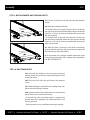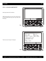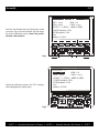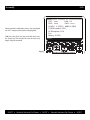
1
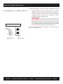
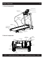
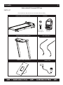
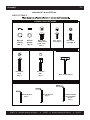
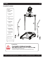
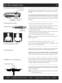
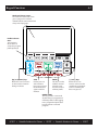
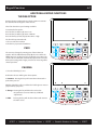
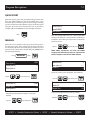
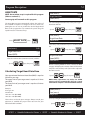
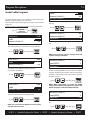
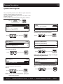
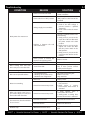
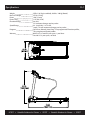
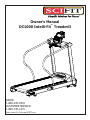
Owner’s Manual
DC1000 Intelli-Fit Treadmill
TM
SALES:
1-800-278-3933
CUSTOMER SERVICE:
1-800-745-1373
Order online 24/7 at www.SCIFIT.com
This page purposely left blank
Important Safety Instructions
Read all instructions before using your SCIFIT exercise machine!
Save these instructions!
DANGER!
Connect to a properly grounded outlet only. See Power Requirements
below. Also, always unplug this machine from the electrical outlet
immediately before cleaning and any servicing of the machine.
WARNING!
1.
Close supervision is necessary when exercise machine is used
near children or disabled persons. Keep children away from
treadmill deck, especially when in operation.
2.
Use the exercise machine only for its intended use as described
in this manual. Do not use attachments not recommended by
the manufacturer.
3.
To make any adjustment during your workout, STOP the
machine and make the necessary adjustments.
4.
Never operate the exercise machine if it has a damaged electrical
power cord or plug, if it is not working properly, or if it has been
damaged. Call the SCIFIT product support department for
further information about repair options.
5.
Keep the electrical power cord away from heated surfaces, and
from the elevation mechanism.
6.
Never operate the machine with the air openings blocked. Keep
the air openings free of lint, hair and other debris.
7.
Never drop or insert any object into any opening.
8.
Do not use outdoors.
9.
Do not operate where aerosol (spray) products are being used
or in an oxygen rich environment.
10.
To disconnect, turn off the power switch and unplug from the
wall outlet
To minimize the risk of electric shock:
To reduce risk of burns, fire, electric
shock, or injury to persons:
SCIFIT • Scientific Solutions for Fitness • SCIFIT • Scientific Solutions for Fitness • SCIFIT
Important Safety Instructions
Power Requirements – D
C1000-INT (100-110V)
Figure A: Grounded Outlet Diagram
1.
SCIFIT’s DC1000-INT(100-110V) treadmill requires a 110 Volt/ 15
AMP circuit. The circuit must have a minimum of 12 gauge wire.
Contact a qualified electrician to have one installed if needed.
Insufficient power may cause your treadmill to function
improperly and will void the warranty.
2.
DANGER: Improper connection of the equipment
grounding conductor can result in a risk of electric shock. Check
with a qualified electrician or serviceman if you are in doubt as
to whether the product is properly grounded. Do not modify
the plug provided with the product - if it will not fit the outlet,
have a proper outlet installed by a qualified electrician
If you or your electrician have any questions, contact SCIFIT Product
Support at 1-800-745-1373.
Plug grounding
pin
Grounded outlet
SCIFIT • Scientific Solutions for Fitness • SCIFIT • Scientific Solutions for Fitness • SCIFIT
Table of Contents
Introduction
Product Components
Assembly
Installation and Maintenance
Heart Rate Transmitter Strap
1.1 to 1.2
2.1
3.1 to 3.16
4.1 to 4.2
5.1
Keypad Functions
6.1 to 6.2
Program Descriptions
7.1 to 7.5
Set-Up Mode
8.1 to 8.2
Troubleshooting
Warranty Policy and Service Procedures
9.1
10.1 to 10.5
Specifications
11.1
Warranty card
12.1
Introduction
1.1
Thank you for your purchase of the SCIFIT treadmill. We have incorporated
the finest technology and ergonomic design into this machine to assist you
in achieving your fitness goals. However, for your safety, please adhere to
the following recommendations before you begin to exercise.
FITKEY™
Consult Your Physician
Warm Up and Cool Down
Exercise at Your Own Level
Stay Within Your Target Heart Rate Zone
Your SCIFIT treadmill may be equipped with a FITKEY receptical. Contact
SCIFIT to learn more about this exercise protocol and documentation
software.
Consult your physician or medical specialist before participating in any
exercise program, especially if you are pregnant, or if you are suffering
from: heart disease, respiratory disease, diabetes, hypertension, high
blood pressure, elevated cholesterol, arthritis or any other diseases or
physical complaints.
To prevent muscle injuries and soreness, you should always warm up
(at least 5 minutes) and cool down (at least 5 minutes) by doing a series
of stretches before and after each workout.
Increase your exercise level gradually, and avoid sudden, erratic,
or careless exercise. The key to a successful exercise program is
consistency.
For healthy beginners, start exercising two to four days a week with
your heart rate in the target zone for about twenty (20) minutes each
day.
Your approximate maximum heart rate (MHR) is equal to 220 minus
your age. The upper limit of your target zone is equal to 0.85 times
your MHR. The lower limit of your target zone is equal to 0.60 times
your MHR.
For example, if you are 40 years old, your approximate MHR is equal to
180 (220 minus 40). Therefore, your target zone is between 60% of 180
(0.60 x 180) = 108, and 85% of 180 (0.85 x 180) = 153. So for a 40 year
old, the target heart rate zone is between 108 and 153.
Try to stay within the target heart rate zone to achieve optimal fitness
training. Avoid exceeding your maximum target heart rate as this
may cause stress, fatigue, and/or injuries to your body. At the same
time, you need to sustain the intensity level of your exercise above the
minimum target heart rate in order to achieve
CAUTION: When To Stop Exercising
Train Intelligently
Stop exercising immediately if you feel nausea, dizziness, sharp pain,
or any other physical discomfort. Do not resume until you consult with
a physician.
To ensure a future of good health, you should always eat well balanced
meals, drink plenty of fluid/water during a workout, and stay fit by
exercising intelligently.
SCIFIT • Scientific Solutions for Fitness • SCIFIT • Scientific Solutions for Fitness • SCIFIT
Introduction
1.2
Safe Use of Treadmill
• The safest position is with your feet on each top side cover,
straddling the running belt. Step onto the running belt after
you have started the treadmill to prevent injury.
• To balance yourself look straight ahead and hold on to the
side handlebars or front handlebar.
• It is common to feel slightly dizzy after getting off the treadmill
after a workout. This is because the ground has been moving
under you. To help avoid this, turn the treadmill down to a
slow speed and cool down for several minutes before getting
off.
• A treadmill is not for children to play on. Use common sense
when operating this treadmill and observe all caution stickers.
• Keep hand and fingers away from all areas that could cause
injury such as the front and back rollers.
• Never place rear of the treadmill near an obstruction.
• Never put any substance underneath the treadmill running
belt
• Do not spill any liquid on the treadmill running belt.
• Maximum user weight is 375 lbs/ 170 kg.
Emergency Stop Magnet is
located on the front handlebar
MAGNET
The Emergency Stop Magnet/Clip
• To stop the treadmill quickly in emergency situations pull the
magnet from the Emergency Stop housing.
Attach the Emergency Stop Clip to your clothing, in the front
chest area, using the Grip Teeth (see Figure to left) before
beginning your workout. If you should fall or slip backward
during the workout, the magnet will pull away from the
Emergency Stop housing and the running belt will come to a
rest
CLIP
SCIFIT • Scientific Solutions for Fitness • SCIFIT • Scientific Solutions for Fitness • SCIFIT
Product Components
2.1
1. External components
Water Bottle Holder
LCD Intelli-Fit Console
Emergency Stop
Magnet/Clip
Contact Heart Rate
Easy Grip L & R
Side Handlebars
LH & RH
Uprights
Motor Cover
Non-Skid
Side Covers
L & R End Caps with
Walkbelt Alignment
Bolt Access
Walkbelt
Adjustable
Rear Feet
2. Internal components
110V Actuator
3hp Motor
110V Motor
Controller Board
On/Off
Power Switch
Thermal Fuse
AC Inlet
Transformer
Drive
Belt
Front Roller
& Pulley
Speed Sensor
SCIFIT • Scientific Solutions for Fitness • SCIFIT • Scientific Solutions for Fitness • SCIFIT
Assembly
PARTS LIST
3.1
Order online 24/7 at www.SCIFIT.com
Please make sure all parts below are in the box before assembly.
MAIN UNIT WITH MOTOR COVER
CONSOLE
M5 x 12mm
Screw (Qty. 4)
UPRIGHT WELDMENT ASSEMBLY
CONSOLE MOUNT WELDMENT
Console
SIDE HAND RAILS
POWER CORD
NO
C
Assembly
3.2
Order online 24/7 at www.SCIFIT.com
PARTS LIST CONT’D
Please make sure all parts below are in the box before assembly.
MAGNET/CLIP
2-WIRE E-STOP CABLE
EXTENSION
LOWER SIDE RAIL COVERS
4-WIRE CHR CABLE
EXTENSION
10-WIRE MAIN CABLE
EXTENSION
3.3
Assembly
Order online 24/7 at www.SCIFIT.com
PARTS LIST CONT’D
ASSEMBLY BAG CONTAINING
M8 Lock
Washer
(Qty. 6)
M8 Flat
Washer
(Qty. 6)
M8 x 50mm
Screw
(Qty. 2)
M8 x 45mm
Bolt
(Qty. 2)
M4 Hex Wrench
(Qty. 1)
SCIFIT
M5 x 12mm
Screw (Qty. 2)
M8 x 16mm
w/Blue Loctite
Patch Screw
(Qty. 6)
Scientific Solution for Fitness
M6 T-Handle (Qty.1)
M5 Hex Wrench
(Qty. 1)
SCIFIT
M6 x 15mm
Screw (Qty. 4)
Combination M6
Hex and Phillips
Wrench
(Qty. 1)
Scientic Solutions for Fitness
SCIFIT
Assembly
3.4
Assembly Procedures
6
Unpack
and assemble
as follows:
1. Install upright
weldment
7
2. Install side hand
rails
3. Attach lower side
hand rail covers
4. Attach cable
extensions to
console
5. Attach console
mount weldment
to console
6. Attach console
w/weldment to
upright assembly
7. Attach magnet
and clip to the
machine
9
8. Power-Up
10 11
9. Belt Alignment
10. Belt Tension
11. Incline Calibration
Assembly Note
• All power cables should be grounded.
.
• Verify dust and debris are removed from the machine before using.
SCIFIT
Scientific Solution for Fitness
SCIFIT
Scientic Solutions for Fitness
SCIFIT
Assembly
3.5
NOTE: 1. The following assembly instructions for the DC1000 will require two people
2. Refer to section 3.3 for hardware indentification
STEP 1: UPRIGHT WELDMENT INSTALLATION
3.4
1a. Carefully hold the upright weldment assembly over the
treadmill main body frame and attach the 10-wire connector
from the right upright to the 10-wire connector coming
from the treadmill main body frame upright extension.
Connect
Cables Here
Frame
Upright
Extension
.
3.4
1b. Push the connected cables back into the frame and
carefully slide the left and right uprights onto the frame
upright extensions of the main treadmill body.
.
SCIFIT
Scientific Solutions For Fitness
SCIFIT
Scientific Solutions For Fitness
SCIFIT
Assembly
3.6
STEP 1: UPRIGHT WELDMENT INSTALLATION CONT’D
M8 Flat Washer x 2
M8 Split Washer x 2
M8 x 16mm
Socket HD Screw x 2
Hardware Required:
Tool Required:
(Qty. 2) M8 Split Washers
M6 T-Handle Hex Wrench
(Qty. 2) M8 Flat Washers
(Qty. 2) M8 x 1.25 x 16mm Socket Button HD Screws
1c. Slide in order (Qty. 1) M8 Split washer, then (Qty. 1) M8 Flat
washer onto the first M8 screw, then LOOSELY tighten the
screw into the upper mounting hole located on the outside
of the right upright with a M6 T-handle hex wrench. NOTE:
The screw will be secured properly in a later step.
1d. Slide in order (Qty.1) M8 Split washer, then (Qty. 1) M8 Flat
washer onto the second M8 screw, then LOOSELY tighten the
screw into the lower mounting hole located on the outside of
the right upright with a M6 T-handle hex wrench as. NOTE:
The screw will be secured properly in a later step.
Hardware Required:
(Qty. 1) M8 Split Washer
(Qty. 1) M8 Flat Washer
(Qty. 1) M8 x 1.25 x 16mm Socket Button HD Screw
M8 Flat Washer
M8 Split Washer
M8 x 16mm Socket
HD Screw
1e. Slide in order (Qty.1) M8 Split washer, then (Qty. 1) M8 Flat
washer onto the M8 screw, then LOOSELY tighten the screw
into the mounting hole located on the inside of the right
upright with a M6 T-handle hex wrench as shown. NOTE: The
screw will be secured properly in a later step.
1f. Repeat steps 1c, 1d and 1e for the left upright. NOTE: The
screws will be secured properly in a later step.
SCIFIT
Scientific Solutions For Fitness
SCIFIT
Scientific Solutions For Fitness
SCIFIT
Assembly
3.7
STEP 2: SIDE HAND RAIL INSTALLATION
Align
Holes
2a. Starting on the right side, take one of the side hand rails
and slide the upper end (has two holes on bottom side of
tube) onto the extended tube coming from the upright
weldment and align the holes of the hand rail with the holes
of the tube extension from the upright.
Hardware Required:
Tool Required:
(Qty. 2) M6 x 1.0 x 15mm
Socket Button HD Screws
M4 Hex Wrench
2b. Use a M4 Hex wrench to LOOSELY secure the hand rail
with (Qty.2) M6 x 15mm socket button head screws.
SCIFIT
Scientific Solutions For Fitness
SCIFIT
Scientific Solutions For Fitness
SCIFIT
Assembly
3.8
STEP 2: SIDE HAND RAIL INSTALLATION CONT’D
Hardware Required:
Tool Required:
(Qty. 1) M8 x 1.25 x 50mm
Socket Button HD Screw
M5 Hex Wrench
2c. Align the larger screw hole of the lower side hand rail
with the hole of the frame mounting bracket, then use a M5
hex wrench to LOOSELY attach a M8 x 50mm socket button
head screw .
2d. Repeat steps 2a, 2b and 2c for the left side.
2e. Return to the screws attaching the lower part of the upright
weldment assembly from step 1 and using a M6 T-handle hex wrench
tightly secure the three screws on both the right and left uprights.
2f. Using a M4 hex wrench tightly secure the two screws on
both the upper right and left side hand rails .
2f. Using a M5 hex wrench tightly secure the screw on both the
lower right and left side hand rails .
SCIFIT
Scientific Solutions For Fitness
SCIFIT
Scientific Solutions For Fitness
SCIFIT
Assembly
3.9
STEP 3: ATTACH LOWER SIDE HAND RAIL COVERS
Hardware Required:
Tool Required:
(Qty.1) M5 x .8 x 12mm
Phillips HD Screw
M6/Phillips combo hex
wrench
3a. Starting on the right side take the first of the two lower
side hand rail covers and align the cover screw hole with
lower side hand rail screw hole, then using the phillips end
of the combo wrench and secure the cover with a M5 x
12mm Phillips screw.
3b. Repeat step 3a for the left side.
STEP 4: ATTACH CABLE EXTENSIONS TO CONSOLE (See section 3.2 for cable identification)
Cables Required:
P1
10 - Wire
Main Cable
(Qty.1) 10 wire MAIN cable
(Qty.1) Dual 2 wire CHR cable
(Qty.1) 2 wire E-STOP cable
P3 P4
4a. Place the console face down on a flat surface.
Dual 2 - Wire
CHR Cable
P11
SCIFIT
2 - Wire
E-Stop Cable
Scientific Solutions For Fitness
4b. Looking in from the rear of the console, attach the 10
wire female end of the main cable to connector P1 .
4c. Attach the Dual 2 wire CHR (Dual male housing end)
cable to connectors P3 and P4.
4d. Attach the 2 wire E-Stop cable to connector P11.
SCIFIT
Scientific Solutions For Fitness
SCIFIT
Assembly
3.10
STEP 5: ATTACH THE CONSOLE MOUNT WELDMENT TO CONSOLE
Console
Mounting
Bracket
Secure Console
Mount With
Remaining
M5 x 12mm
Screws
Hardware Required:
Tool Required:
(Qty. 4) M5 x .8 x 12mm
Phillips HD Screw
Phillips screw driver
5a. Remove the four screws that are inserted into the rear
enclosure of the console and place to the side.
5b. Route the Main, CHR and E-Stop cables through the
exit hole on the console mounting bracket, then align the
mounting bracket holes with the console mounting holes .
Exit Hole
M5 x 12mm Screw
To Secure Ring Lug
Magnet/Clip
Ring Lug
5c. Take the ring lug end of the Magnet/Clip tether and
using a phillips screw driver secure it to the lower left corner
of the console mount weldment with (Qty. 1) M5 x 12mm of
the screws previously removed in step 5a .
5d. Using a phillips screw driver finish securing the console
mount weldment with (Qty. 3) M5 x 12mm phillips head
screws previously removed in step 5a.
STEP 6: ATTACH CONSOLE WITH MOUNTING BRACKET TO THE UPRIGHT ASSEMBLY
Connect cables here,
then push them into
the center frame
Pull cables out
from center frame
6a. Pull out the Main, CHR and E-Stop cables from the
machine center frame and connect them to the Main, CHR
and E-Stop extension cables coming from the console.
6b. After connecting, push all the cables back into the
center frame and align the two console mounting bracket
holes with the two center frame mounting holes..
SCIFIT
Scientific Solutions For Fitness
SCIFIT
Scientific Solutions For Fitness
SCIFIT
Assembly
3.11
STEP 6: ATTACH CONSOLE WITH MOUNTING BRACKET TO THE UPRIGHT ASSEMBLY CONT’D
Hardware Required:
Tool Required:
(Qty. 2) M8 x 1.25 x 45mm
Socket Cap HD screws
M6 T-handle wrench
6c. After aligning the console mount weldment holes with
the center frame mounting holes, use a M6 T-handle and
(Qty. 2) M8 x 45mm socket cap screws to secure it in place.
STEP 7: ATTACH MAGNET AND CLIP TO THE MACHINE
Part Required:
(Qty. 1) Magnet/Clip
7a. Place the magnet end of the tether onto the Emergency
stop housing.
SCIFIT
Scientific Solutions For Fitness
SCIFIT
Scientific Solutions For Fitness
SCIFIT
Assembly
3.12
STEP 8: POWER-UP
Part Required:
(Qty. 1) AC Power Cord
8a. Verify the On/Off switch is in the “OFF” position, then
plug in the right angle end of the AC power cord into the AC
power inlet located at the front of the machine.
8b. Plug the other end of the AC power cord into the wall
outlet, then flip the On/Off switch to the “ON” position and
the console turn on .
STEP 9: BELT ALIGNMENT AND TENSION
Tool Required:
M6 T-Handle Wrench
Tightens Belt
e
Clockwis
lockwise
C
NOTE: If belt had been replaced begin at step 9a.
If you are just making making minor adjustments
begin at step 9c.
9a. Center the walkbelt manually between the side covers.
9b. Insert an M6 T-Handle wrench into the right end cap
and turn the handle clockwise, then place the T-handle
into the left end cap and equally turn the handle clockwise.
Continue doing this until the walk belt becomes taunt
SCIFIT
Scientific Solutions For Fitness
SCIFIT
Scientific Solutions For Fitness
SCIFIT
Assembly
3.13
STEP 9: BELT ALIGNMENT AND TENSION CONT”D
9c. Press the “Quick Start” key and adjust the belt speed to
2 mph.
9d. Watch the tracking of the belt:
vement
Belt mo ise turn
kw
c
lo
c
with
Clockwise
vement
Belt mo ise turn
kw
c
lo
with c
* If the belt tracks to the right, place the the T-handle into
the right end cap belt adjustment hole and turn the handle
clockwise a 1/4 turn at a time to make the belt move to the
left until centered
* If the belt tracks to the left, place the the T-handle into
the left end cap belt adjustment hole and turn the handle
clockwise a 1/4 turn at a time to make the belt move to the
right until centered
9e. When the belt is tracking in the center consistantly,
increase the belt speed to 5 mph and continue to adjust the
belt according to step 9d if needed.
9f. If adjustments are no longer needed, reduce the speed
to zero and exit the “Quick Start” workout, then proceeed to
the “BELT TENSION TEST”.
Clockwise
STEP 10: BELT TENSION TEST
10a. Start with the machine in the main menu (picture of
woman shown) and stradle the treadmill placing your feet
on the side covers.
10b. Press the “Quick Start” key and increase the speed to
2 mph.
10c. While holding the side hand rails carefully place your
feet on the belt and begin walking.
10d. Stomp one foot in front of the other just in front of the
motor cover to try to make the belt stop.
* If the belt slips, than more belt tension is required and
step 9b needs to be repeated, also verifying the belt is still
running centered.
* If the belt does not slip, no futher tensioning is required.
SCIFIT
Scientific Solutions For Fitness
SCIFIT
Scientific Solutions For Fitness
SCIFIT
Assembly
3.14
STEP 11: INCLINE CALIBRATION TEST
Select Workout or Insert Fitkey
11a. Apply power to the machine.
11b. Starting at the main screen. Press the [One Dot],
[Six Dot] and Eelevation [Up] arrow keys at the same
time (Fig.1)
Manual
H eart R ate
G rade
P rofile
S peed
P rofile
Fig.1
P OT : xxxx
MP H: 0.4
RPM: xxxx
PWM: xxxx
H E A R T : 0 ( B P M ) HAND: 0 (BPM)
C S AF E loopback: F AIL
R F ID loopback: F AIL
F an
B attery: 0.200V
Then the screen in Figure 2 will appear
1
2
3
4
5
6
Fig.2
SCIFIT
Scientific Solutions For Fitness
SCIFIT
Scientific Solutions For Fitness
SCIFIT
Assembly
3.15
Select Workout or Insert Fitkey
P OT : xxxx
MP H: 0.4
RPM: xxxx
PWM: xxxx
H E A R T : 0 ( B P M ) HAND: 0 (BPM)
11c. Press the Elevation [Up] and [Down] keys at the
same time (Fig.3) and the treadmill will then begin
the incline calibration process. Note: The process
will take a few moments
C S AF E loopback: F AIL
R F ID loopback: F AIL
F an
B attery: 0.200V
1
2
3
4
5
6
SCI FI T
Fig.3
Select Workout or Insert Fitkey
P OT : xxxx
MP H: 0.4
RPM: xxxx
PWM: xxxx
H E A R T : 0 ( B P M ) HAND: 0 (BPM)
C S AF E loopback: F AIL
R F ID loopback: F AIL
F an
B attery: 0.200V
During the calibration process, the “POT” category
will be highlighted in yellow (Fig.4)
Fig.4
SCIFIT
Scientific Solutions For Fitness
SCIFIT
Scientific Solutions For Fitness
SCIFIT
Assembly
3.16
Select Workout or Insert Fitkey
P OT : xxxx
MP H: 0.4
RPM: xxxx
PWM: xxxx
H E A R T : 0 ( B P M ) HAND: 0 (BPM)
When the incline calibration process has completed
the “POT” category will become unhighlighted
C S AF E loopback: F AIL
R F ID loopback: F AIL
F an
B attery: 0.200V
11d. Press the [One Dot] key and hold, then press
the [Stop] key. The console will reset and you may
begin using the treadmill.
Fig.5
SCIFIT
Scientific Solutions For Fitness
SCIFIT
Scientific Solutions For Fitness
SCIFIT
Installation and Maintenance
4.1
Placement
Avoid placing the treadmill in direct sunlight, in areas of extreme
temperature or humidity or where the equipment may be splashed
with any fluid. This treadmill is intended for indoor use only. Position
the treadmill so the plug is easily accessible.
Allow a minimum of 20” (508mm) between the wall and other
treadmills when in use.
Allow a safety area of 79” x 36” (2000mm x 914mm) square around
the treadmill when in use.
Moving
The treadmill has wheels at the front of the machine attached to the
incline weldment assembly for easy handling.
These built-in wheels are designed for short distance relocation of the
treadmill, not for moving or delivery.
To move a short distance, incline the machine to 10%, then unplug
from the wall outlet, lift the rear of the treadmill and move.
CAUTION:
*When moving the machine it is strongly recommended that two
people be used.
*Please use furniture dollys to move the treadmill longer distances.
After intense training, always clean your SCIFIT product. Perspiration that stays in contact with the frame, casing, and console may
cause rust or other damage. Clean surfaces with water and mild soap, then dry with a towel.
Follow the schedule below to maintain optimal performance of a SCIFIT treadmill
Treadmill Maintenance Schedule
Component
Use
When
By Whom
Frame, Motor Cover,
Console
Damp Cloth
Daily
Facility
LCD Screen
LCD TV Screen soft
cleaning cloth
Daily
Facility
Inside Motor Cover
Vacuum
Monthly
Facility
Inspect Drive Belt
Visual - Cracks in
belt, Belt material
deteriation, etc..
Monthly
Facility
Inspect Walkbelt
Visual - Cracking,
Fraying, Belt slippage,
Replace if damaged
Monthly
Facility
Inspect Walk Deck
Visual - Wear on
the deck, Cracks,
Replace if Damaged.
Flip once a year
Monthly
Facility
Front/Rear Rollers
Damp cloth.
Replace if Damaged
As Needed
Facility
Actuator Elevation
Screw Shaft
General purpose
grease
Annually
Facility
SCIFIT • Scientific Solutions for Fitness • SCIFIT • Scientific Solutions for Fitness • SCIFIT
Installation and Maintenance
4.2
UNITED STATES CUSTOMER SERVICE
For assistance in the service of SCIFIT products;
phone : +1-800-745-1373
fax : +1-918-359-2045
e-mail: [email protected]
The Product Support department is available by means
of e-mail. A voice mail service is available 24 hours
a day for recording messages to request technical
support and to order replacement parts. Our mailing
address is:
SCIFIT Systems Inc.
5151 S. 110th E. Ave.
Tulsa, OK 74146
USA
UK & EUROPEAN CUSTOMER SERVICE
phone : +44 1344 300022
fax: +44 1344 868838
e-mail: [email protected]
SCIFIT LTD (UK)
Lexham House
Forest Road
Binfield
Berkshire, RG42 4HP
UK
Company Number: 5970624 (UK)
*COUNTRIES OUTSIDE OF UK & EUROPE
PLEASE USE USA CONTACT NUMBERS*
Order online 24/7 at www.SCIFIT.com
SCIFIT • Scientific Solutions for Fitness • SCIFIT • Scientific Solutions for Fitness • SCIFIT
Heart Rate Transmitter Strap
5.1
Uses of the Heart Rate Transmitter Strap
Size Adjuster
Transmitter
Snap Buttons Sensor
Activating The Transmitter
The wireless heart rate transmitter strap accessory is a useful device
if you desire continuous feedback on your current heart rate during a
workout.
The Heart Rate Control program enables the user to set-up a target
heart rate. Through real-time monitoring of the user’s heart rate, the
console maintains the user’s heart rate at or below this established
target rate by decreasing the elevation if the user’s heart rate exceeds
the target.
To activate the HR Transmitter strap, follow the steps below:
Unhooking Strap
Snap Button
1. U
nhook the strap by slightly twisting the snap button on either side
outward until you can pull the button through the hole.
2. Moisten the backside of the sensor, then adjust the strap below the
pectoral muscle or breasts.
3. Position the strap so that the transmitter sensor is directly in the
center of the chest as shown in the illustration.
4. The sensor will begin to monitor and transmit your heart rate.
NOTE: For best results place the transmitter under your garment, so it
may contact the skin.
De-activating the Transmitter
The transmitter is automatically turns off when it is removed.
Be sure to wipe the strap thoroughly with a dry cloth after each
workout to ensure reliable operation.
Signal Interference
Inaccurate heart rate readings may occur if you use the transmitter
within an area near other sources of electromagnetic radiation.
Examples of such sources include: other fitness equipment, other
heart rate transmitters, and televisions. To reduce erroneous readings,
be sure to allow a minimum of 1 meter between each radiation source.
CAUTION: Users with Pacemakers
Contact Heart Rate
CHR Grips
Never use the Heart Rate Transmitter strap if you wear an electrical
heart pacemaker or other electrical medical device. This could be
extremely dangerous since the Heart Rate Transmitter can interfere
and cause electrical disturbances to those devices.
The Contact heart rate is located directly in front of the user. Simply
grip the contact grips lightly, after a short delay the pulse reading will
appear on the display.
NOTE: If a transmitter heart strap is worn, this will over ride the reading
of the contact heart rate.
SCIFIT • Scientific Solutions for Fitness • SCIFIT • Scientific Solutions for Fitness • SCIFIT
Keypad Functions
6.1
Work Level Status Screen The work level status LCD screen
gives a progressive real-time
indication of the current work level
of any and all programs.
Profile Selection
Area This location is
where the user
selects the program
profile preferred.
Manual
[Up] and [Down] Keys
Allows the user to increase
or decrease the elevation
during a workout.
Heart Rate
Grade
Profile
STOP
Used to pause or
exit a workout.
Press once to pause
the workout, Press
again to exit the
workout
Speed
Profile
ENTER
This key is used to
validate selected
values the user
has choosen for a
workout profile.
[+] and [-] Keys
Allows the user to
increase or decrease the
speed during a workout.
Is also used during the
data entry process
QUICK START
This key provides a one-touch
“Quick Start” pre-programmed
workout profile or after logging
into a program the“Quick Start”
key will activate a selected
program.
SCIFIT • Scientific Solutions for Fitness • SCIFIT • Scientific Solutions for Fitness • SCIFIT
Keypad Functions
6.2
ADDITIONAL KEYPAD FUNCTIONS
THE FAN OPTION
Anytime during a workout the user has the option to activate
the dual internal cooling fans of the console.
These fans have three speed settings available.
To activate the fan option:
Press the fan (six dot) key (A) once- Low
Press the fan (six dot) key (A) twice - Medium
Press the fan key (six dot) key (A) three times - High
The fan will stay activated until:
1. The user exits the workout
2. The fan key is pressed a fourth time
B
A
Pace
Fan
PACE
The user may change the running pace of the workout at
anytime. Press the PACE (four dot) key (B), then use either the
SPEED “increase” or “decrease” keys to adjust the pace time. The
speed of the treadmill will automatically adjust to the new pace
time by decreasing with a longer pace time or increasing with a
shorter pace time.
PAUSING
1. Press the STOP key (C) once
At this time the user will be given three options.
D. Continue - Pressing this key will restart the workout at the
point it was paused.
NOTE: A slight delay will occur before the belt begins to move or
just press the [+] key once.
E. Change - Pressing this key will take the user back to
the parameter screen to make any additional
adjustments.
F. STOP -
D
E
F
Continue
Change
Stop
C
P
ressing this key will exit the workout and return to
the main screen.
SCIFIT • Scientific Solutions for Fitness • SCIFIT • Scientific Solutions for Fitness • SCIFIT
Program Descriptions
7.1
QUICK START
Allows the user to get on and go without having to enter data.
Press the QUICK START key and the treadmill starts at the
minimum speed, minimum grade and time begins counting
up. The user then manually adjusts the speed and incline grade
using the Speed “Increase” and Decrease” keys or the Incline
using the [UP] and [DOWN] arrow keys during the workout.
Press
Allows the user to initially set the Speed and Incline grade in
the data entry screen. These settings do not change unless the
user manually adjusts the speed using the Speed “Increase” and
Decrease” keys or the Incline using the [UP] and [DOWN] arrow
keys during the workout.
MANUAL
Then
15:00
.4
-- --
Time (mm:ss)
Speed (MPH)
Pace (mm:ss)
Select the Time (maximum 99 min.) with the
Speed
Speed
Speed (MPH)
Pace (mm:ss)
Grade (%)
.4
-- -0
Select the incline grade (maximum 10%) with the
keys, then press
Time (mm:ss)
Speed (MPH)
Pace (mm:ss)
keys, then press
NOTE: When adjustments are made, the SPEED
category will automatically adjust to a speed it will
take to complete 1 mile for the PACE selected.
Speed
15:00
.4
-- --
Select the speed (maximum 9 mph or 14.5 km/h)
with the
keys, then press
Pace (mm:ss)
Grade (%)
Weight (lbs)
-- -0
150
Select your weight (maximum 375 lbs/170 kg)
with the
Speed
15:00
.4
-- --
After the starting SPEED has been selected, the PACE
category will display the amount of time it will take to
complete 1 mile at that speed. If you wish to adjust the
Pace time use the
MANUAL
Press
Time (mm:ss)
Speed (MPH)
Pace (mm:ss)
keys, then press
keys, then press
SCIFIT • Scientific Solutions for Fitness • SCIFIT • Scientific Solutions for Fitness • SCIFIT
Program Descriptions
7.2
HEART RATE
NOTE: A transmitter strap is required for this program
(Refer to section 5.1).
Contact grips will not work on this program.
The Heart Rate program automatically adjusts the incline of
the treadmill in response to changes in the user’s heart rate,
putting the user as near as possible the desired Target Heart
Rate. In this program the user controls the speed using the
Speed “Increase” or “Decrease” keys.
Press
HEART RATE
Time (mm:ss)
Target Heart Rate
Speed (MPH)
15:00
120
.4
(see Calculating Heart Rate Zone) Select your Target
Heart Rate with the
Speed
keys, then press
Time (mm:ss)
Target Heart Rate
Speed (MPH)
Then
15:00
120
.4
Select the speed (maximum 9 mph or 14.5 km/h) with
the
15:00
120
.4
Time (mm:ss)
Target Heart Rate
Speed (MPH)
Select the workout time (maximum 99 min.) with the
Speed
keys, then press
Calculating Target Heart Rate Zone
Your approximate Maximum Heart Rate (MHR) is equal to
220 minus your age.
The upper limit of your target zone is equal to .85 times
your MHR.
The lower limit of your target zone is equal to .60 times
your MHR.
Example:
Your age is 40
220-40=180
180 x .85 = 153 (Max MHR)
180 x .65 = 108 (Min MHR)
These values are based upon averages. Always consult your
physician to establish the proper heart rate zone for your
individual health condition.
Speed
keys, then press
Target Heart Rate
Speed (MPH)
Pace (mm:ss)
120
.4
-- --
After the starting SPEED has been selected, the PACE
category will display the amount of time it will take to
complete 1 mile at that speed. If you wish to adjust the
Pace time use the
Speed
keys, then press
NOTE: When adjustments are made, the SPEED
category will also automatically adjust to a speed
it will take to complete 1 mile for the PACE selected.
Speed (mm:ss)
Pace (mm:ss)
Weight (lbs)
.4
-- -150
Select your weight (maximum 375 lbs/ 170 kg) with the
Speed
keys, then press
SCIFIT • Scientific Solutions for Fitness • SCIFIT • Scientific Solutions for Fitness • SCIFIT
Program Descriptions
7.3
Grade Profile Programs
The grade profile provides seven different incline dependent
workout contours that the user may select.
The incline will automatically adjust up or down as the workout
progresses.
Speed can only be adjusted manually during these workouts.
Press
GRADE
PROFILE
Profile
Minimum Grade (%)
Maximum Grade (%)
0.0
10
Select the maximum incline grade (maximum10%)
with the
Speed
keys, then press
Then
15:00
Time (mm:ss)
Profile
Minimum Grade (%)
0.0
0.0
10
.4
Minimum Grade (%)
Maximum Grade (%)
Speed (MPH)
Select the speed (maximum 9mph or 14.5 km/h) with
the
Select the workout time (maximum 99 min.) with the
Speed
Speed
keys, then press
keys, then press
NOTE: The speed may only be changed manually
anytime during the workout.
15:00
Time (mm:ss)
Profile
Minimum Grade (%)
0.0
Select from seven different workout contours
(see section 7.4) with the
Speed
After the starting SPEED has been selected, the PACE
category will display the amount of time it will take to
complete 1 mile at that speed. If you wish to adjust the
Pace time use the
keys, then press
Speed
15:00
Time (mm:ss)
Profile
Minimum Grade (%)
0.0
Select the minimum incline height with the
Speed
10
.4
-- --
Maximum Grade (%)
Speed (MPH)
Pace (mm:ss)
keys, then press
NOTE: Do not exceed the Maximum incline grade
selected in the next step.
keys, then press
NOTE: When adjustments are made the SPEED
category will automatically adjust to a speed it will
take to complete 1 mile for the PACE selected.
10
.4
150
Maximum Grade (%)
Speed (MPH)
Weight (lbs)
Select your weight (maximum 375 lbs/170 Kg) with
the
Speed
keys, then press
SCIFIT • Scientific Solutions for Fitness • SCIFIT • Scientific Solutions for Fitness • SCIFIT
Program Descriptions
7.4
The following are Grade and Speed workout profiles available for selection
COURSE
MULTI-PEAKS
SPRINT
RAMP
TWIN PEAKS
PEAK
PROGRESSIVE
SCIFIT • Scientific Solutions for Fitness • SCIFIT • Scientific Solutions for Fitness • SCIFIT
Program Descriptions
7.5
Speed Profile Programs
The speed profile provides seven different speed dependent
workout contours that the user may select.
The speed will automatically adjust faster or slower as the
workout progresses.
Incline can only be adjusted manually during these workouts.
Press
SPEED
PROFILE
then
Time (mm:ss)
Profile
Minimum Speed (MPH)
15:00
.4
Select the workout time (maximum 99 min.) with the
Speed
15:00
.4
keys, then press
Minimum Speed (MPH)
Maximum Speed (MPH)
Grade (%)
.4
9
0.0
Select the incline grade (maximum 10%) for the
workout with the
Select from seven different workout contours
(see section 7.4 with the)
Speed
.4
9
Select the maximum workout speed
(maximum 9 mph or 14.5 km/h) with the
Speed
keys, then press
Time (mm:ss)
Profile
Minimum Speed (MPH)
Profile
Minimum Speed (MPH)
Maximum Speed (MPH)
Speed
keys, then press
keys, then press
NOTE: The incline grade may only be changed
manually during the workout.
Time (mm:ss)
Profile
Minimum Speed (MPH)
15:00
.4
Select the minimum workout speed
with the
Maximum Speed (MPH)
Grade (%)
Weight (lbs)
Select your weight (maximum 375 lbs/170 Kg) with
the
Speed
Speed
9
0.0
150
keys, then press
keys, then press
NOTE: Do not exceed the Maximum speed you
select in the next step.
SCIFIT • Scientific Solutions for Fitness • SCIFIT • Scientific Solutions for Fitness • SCIFIT
8.1
Set-up Mode
DC1000-INT TREADMILL CONSOLE “SET-UP” DESCRIPTIONS
The following are brief descriptions of Set-Up Mode categories that pertain only to the
SCIFIT -INT treadmill. Additional categories will be seen, which are used for other
SCIFIT products.
Use the [UP] or [Down] arrows to make adjustments. After making adjustments the user may
press [Quick Start] to save and exit the Set-Up mode at anytime.
NOTE: If you pass the category wanted, you can not go backwards.
Press [Quick Start] and re-enter into the Set-Up mode.
ACCESSING THE “SET-UP” SCREEN
Press the [One dot] key, [Six dot] key and [STOP] key at the same time.
The screen will change and display “OVERLAY” as the first category.
Select Workout or Insert Fitkey
Manual
S
Heart Rate
Solutions for Fi
Grade
Profile
Speed
Profile
CIFIT
S
Solutions for Fi
SCI FI T
8.2
Set-up Mode
OVERLAY:
(Production only) Default: Rotary
Indicates the type of membrane switch (Overlay) that has been attached on the console
Press [E N T ER ] to advance
MODEL:
Default: PRO1
Selects the type of machine the console is going to be attached to
Press [E N T ER ] to advance
Default: English
LANGUAGE:
Allows option to select 1 of 6 languages - English, German, Spanish, Dutch, French and Italian
Press [E N T ER ] to advance
Default: U.S.
UNITS:
Allows option to select the type of weight units preferred: US or Metric
Press [E N T ER ] to advance
Default: 19200
B AUD R A T E :
The console may be connected via the COMM port on the rear of the console to a external monitoring
device that can be used to track a user’s progress. The Baud Rate determines the speed of data transfer
from the console to the device.
There are 6 different speed options: 4800, 9600, 19200, 38400, 57600 and 115200.
NOTE: The Baud Rate selected should be the same as the device’s, the data is being transferred to.
Press [E N T ER ] to advance
EDI TO R :
Default: Table
The data entry and set-up mode screens may be seen in two different formats. Use the he Speed “Increase”
and “Decrease” keys to select either TABLE or CAROUSEL.
TABLE
Use the [ENTER] key to advance to the next category. NOTE: You will not be able to go backwards
Use the Speed “Increase” and “Decrease” keys to adjust data within the category.
Use the [QUICK START] key to save.
CAROUSEL
Use the [One dot] or the [Six dot] keys to advance forward or backwards to different categories.
Use the Speed “Increase” and “Decrease” keys to adjust data within the category.
Use the [QUICK START] key to save
Note: If in the CAROUSEL mode, pressing the [ENTER] key takes you back to the main screen and won’t save.
Press [E N T ER ] to advance (if in TABLE mode)
Default: 0.00
UTILIZATION (HOURS):
Tracks the amount of time (in hour increments) the machine has been in use.
NOTE: Hours will not be reset when a software upgrade is done.
Press [Q U I C K S T A R T ] t o s a v e
S
Solutions for Fi
FIT
S
Solutions for Fi
SCI FI T
Troubleshooting
CONDITION
9.1
REASON
SOLUTION
Power cord is not connected
Connect the power cord into wall
outlet or machine
Power switch is on “OFF” position
Turn the power switch to the
“ON” position at the front of the
treadmill
Voltage supply is not available
Check the following:
1. Check if the wall voltage is
present (consult a qualified
electrician).
2. Check cables under the motor
cover
Problem is between the wall
outlet and inverter
Consult a qualified technician for
the following:
1. Verify power is present at the
input side of the line filter with
the power switch in the “ON”
position.
2. Verify power is present at the
output side of the line filter
with the power switch in the
“ON” position.
3. Verify power is present at the
connector that attaches to the
inverter.
Power present to inverter, but
inverter not supplying power
Replace inverter
Roller noise
Roller bearings bad
Replace roller
Noise coming from belt each
time seam passes over the roller
Seam of new belt
Noise goes away after a day or
two, if noise persists contact
SCIFIT product support
Motor making noise
Bearings of motor damaged
Replace motor
Noise at rear part of the frame
1. Treadmill not level
2. Bearings of rear roller noisey
3. Walk belt out of alignment
Adjust the rear leveling feet
Replace rear roller
Align walk belt
Bad motor
Replace motor
Power from inverter not present
1. Verify motor cable is connected
to the inverter
2. Verify power is coming
from inverter when motor is
activated
Power from inverter not present
1. Verify actuator cable is
connected to the inverter
2. Verify power is coming from
inverter when motor is activated
Drive belt is too loose
Adjust the drive belt tension
Drive belt broken
Replace the drive belt
Walk belt tension too loose
Tighten the tension of the walk
belt
Main power does not turn on
Motor is not working
When the “Quick Start” key is
pressed the display is normal, but
the machine will not incline
The motor runs, but the walk belt
does not move
Walk belt slips
SCIFIT
Scientific Solutions For Fitness
SCIFIT
Scientific Solutions For Fitness
SCIFIT
Warranty Policy and Service Procedures
10.1
It is very important that your SCIFIT machine is registered. This can be
done online at http://www.SCIFIT.com/warrantyregistration.shtml or fill out and
mail the registration form at the back of this manual.
SCIFIT Statement of Warranty
SCIFIT warranties new products against defective workmanship and/or materials under
normal and proper use subject to the following limitations:
(a) SCIFIT’s obligation to the original purchaser shall apply to:
Within the United States and Canada both parts and the cost of labor required
to replace or repair a defective product for a period of one (1) year from user/
dealer purchase date as documented by *warranty card and if warranty card
has not been returned by user/dealer, then date of shipment from the factory.
Thereafter, for a period of two (2) years, such obligation shall extend only to the
supply of replacement parts or products with any labor costs associated with
such replacement or repair to be at Buyer’s expense. Refer to clause (e) for
components outside this policy clause.
Outside the United States and Canada replace defective product with no labor
for a period of three (3) years from user purchase date as documented by
*warranty card and if warranty card has not been returned by user then date of
shipment from factory.
*Note: Original purchaser must register their purchased products either by
warranty card return, web site registration or fax to activate warranty period
or shipment date is extent for start of warranty period. A ninety (90) day period
is to be given for warranty registration to allow stock rotation and showroom
stock, thereafter the registration will be the shipment date for the start of the
warranty period.
(b) SCIFIT’s obligation shall be limited to repairing or replacing defective parts.
No allowance shall be granted for repairs made by Buyer without SCIFIT’s prior
written approval. The decision to replace or repair shall be solely at SCIFIT’s
discretion.
(c) SCIFIT’s warranty does not apply to parts requiring replacement or repair due
to normal and abnormal wear and tear, improper use, corrosion (perspiration),
improper maintenance, improper installation, improper rated, grounded or
dedicated electrical circuits or improper storage, nor does it apply where all or
part of the product has been altered from its original state by Buyer or a third
party.
(d) THIS WARRANTY IS IN LIEU OF ALL OTHER WARRANTIES, EXPRESSED
OR IMPLIED, ARISING BY LAW OR OTHERWISE INCLUDING WARRANTY OR
MERCHANTABILITY OF FITNESS FOR PARTICULAR PURPOSE, AND IS IN
LIEU OF ALL OTHER LIABILITIES OF SCIFIT INCLUDING DIRECT, INDIRECT,
SPECIAL
AND CONSEQUENTIAL DAMAGES OR PENALTIES EXPRESSED OR IMPLIED
WHETHER ARISING OUT OF CONTRACT, NEGLIGENCE OR OTHER SORT.
SCIFIT • Scientific Solutions for Fitness • SCIFIT • Scientific Solutions for Fitness • SCIFIT
Warranty Policy and Service Procedures
10.2
SCIFIT STATEMENT OF WARRANTY
(e) The below listed items have the following warranty coverage unless
determined to be defective. These items include, but are not limited to:
Treadmills – AC5000 models
only
Warranty Period
Treadmill belts
12 months
Treadmill belts decks
12 months
Treadmill structure & frame
5 years
Treadmill drive system inclusive of
motor & inverter
5 years
Treadmill Handrails & Handles
Treadmill Heart rate grips
3 years
12 months
Treadmill water bottle holders
90 days
Treadmill trays
90 days
Rotary Products
Warranty Period
Upholstery
12 months
Saddles/Seats
12 months
Rotary Pedals
12 months
Rubber grips
12 months
Heart rate grips
12 months
Rotary structure & Frame
5 Years
Rubber foot Pads (BioFlex)
12 months
Rotary water bottle holders
90 days
Rotary trays
90 days
Accessories Products
Pedal straps
Heart Rate Receiver/Transmitter
Warranty Period
Normal wear & tear
90 days
Low support boots
12 months
High support boots
12 months
Assist gloves
90 days
USB Keys and Lanyards
90 days
(f) Fires, floods, and acts of God, are not covered under this warranty.
SCIFIT • Scientific Solutions for Fitness • SCIFIT • Scientific Solutions for Fitness • SCIFIT
Warranty Policy and Service Procedures
10.3
Freight and Shipping
All SCIFIT products have displayed on the outside packaging “STOP - UPON DELIVERY
INSPECT MERCHANDISE THOROUGHLY NOTING ANY DAMAGE ON RECEIVING
PAPERWORK PRIOR TO SIGNING”.
SCIFIT is not responsible for the repair or replacement of any unit or part damaged during
transit or installation. The customer is responsible for inspection of each unit and part for
shipping damage at time of delivery or installation, and prior to signing receiving paperwork.
The customer is responsible for pursuing all freight damage claims with the appropriate
transit company. If the customer signs an unqualified receipt for freight or damage
goods, the customer is solely responsible for the cost of the repair or replacement for
such freight damage.
Maintenance
After training, always wipe down your SCIFIT exercise
product. Perspiration that continuously settles on
frame, upholstery, casings and control panels may
eventually cause rust or damage. Damage resulting
from lack of maintenance will NOT be covered under
warranty. To clean upholstery, use mild soap and warm
water. Dry with a clean towel. Refer to the mahine’s
maintenance schedule.
SCIFIT • Scientific Solutions for Fitness • SCIFIT • Scientific Solutions for Fitness • SCIFIT
Warranty Policy and Service Procedures
10.4
Product Support
Assistance for the service of SCIFIT products is available by fax +1-918-359-2045. The product
support department is staffed from 7 AM to 5 PM US Central Time Monday through Friday.
A voicemail service is available 24 hours daily for recording messages to request technical
support and to order replacement parts. Our goal is to return every voicemail call within 30
minutes of when it is placed during our normal business hours.
Please have the following information prior to calling technical support:
•
•
•
•
Model number of equipment
Serial number of equipment
Point of contact name and phone number
Detailed description of symptoms encountered.
Installation
SCIFIT is not responsible for the repair or replacement of any unit or part damaged during
installation. The customer is responsible for inspection of each unit and part for damage
at the time of installation. The customer is responsible for pursuing all damage claims
with the installer.
Parts Shipment
During the first 30 days warranty parts will be shipped via overnight delivery.
Determination must be made before 2:00 PM US Central Time on any given weekday for
next day delivery. During the remainder of the first year warranty period, parts
requirements will be filled via ground shipment. The customer will have the option to request
overnight or 2nd day parts shipping, but will be charged the difference between the
ground shipment cost and the overnight or 2nd day cost.
SCIFIT • Scientific Solutions for Fitness • SCIFIT • Scientific Solutions for Fitness • SCIFIT
Warranty Policy and Service Procedures
10.5
Return of Parts
SCIFIT is committed to continual improvement in the equipment we market. In order to
meet this commitment, the rapid return of defective parts is essential. The examination of
the parts by our engineering department leads to changes that insure the same problem
does not re-occur. Thank you in advance for your assistance!
When requested by SCIFIT, defective parts must be returned to the SCIFIT factory within
20 days of receipt of replacement part. Otherwise SCIFIT will expect payment on the parts
invoice net 30 days.
Please follow these three easy steps for returning parts.
Step 1
Keep the box and packing material in which the new parts arrived.
Step 2
A UPS prepaid Return Label will be in the parts box for only those parts that need to be
returned. If no prepaid Return Label is enclosed contact SCIFIT Product Support at 1-800745-1373. When ALL of the parts are received and inspected at the factory, a credit will be
issued for the original parts invoiced. Attention service companies - labor invoices will
NOT be paid until the defective parts are returned to the factory.
Step 3
Wrap the defective part, place it in the box and affix the Return Label for safe return.
Service Labor
Where applicable, the SCIFIT product support personnel will arrange a local field service
technician to provide field support. Every effort will be made to schedule service during 48
business hours (8 hours per business day) following notification of a problem or as soon
as repair parts are available to the field service technician. Where possible, parts will be
supplied in advance of the field service technicians so that the product is repaired with one
call.
Purchased Parts
All purchased parts will carry a 12 month warranty. Refer to Purchased parts shipments and
installation for more details.
This Limited Commercial Warranty supercedes the limited commercial warranty printed
in the “Users Operation Manual” for all SCIFIT Systems, Inc. products.
If you have questions or require additional information, please contact SCIFIT Systems,
Inc. at [email protected]
SCIFIT • Scientific Solutions for Fitness • SCIFIT • Scientific Solutions for Fitness • SCIFIT
Specifications
11.1
Weight
Max User Weight
Power
Power Cord
Elevation Range
222lbs/ 101 Kg (assembled), 309 lbs/ 140 Kg (Boxed)
375 lbs/170 kg.
110V/15 amp
5-15P RA (110V)
0 to 10%,
.5% increment changes per key stroke
0.4 - 9 mph/ 0.6 - 14.5 km/h
.1mph/ .2 km/h increment changes per key stroke
Quick Start, Manual, Heart Rate, 7 Pre-programmed Elevation profiles,
7 Pre-programmed Speed profiles
Within U.S. & Canada 3 years parts, 1 year labor
Outside U.S. 3 years parts, no labor
Speed Range
Programs
Warranty
31.89
(810mm)
57.74
(1466.6mm)
73.35
(1863.1mm)
SCIFIT • Scientific Solutions for Fitness • SCIFIT • Scientific Solutions for Fitness • SCIFIT
This page purposely left blank
SCIFIT
SCIFIT
Serial Number
Business Phone (_____)
SCIFIT
Comment
SCIFIT
www.SCIFIT.com
Scientific Solutions For FitnessTM
Thank You For Choosing
P2278 Rev.B
Referred by SCIFIT User
Saw at ____________________ Tradeshow
Other
Introduced by SCIFIT Dealer
Saw in ______________________ Magazine
Please Check the appropriate box(s) on how you were introduced to SCIFIT:
____Features____Quality____Price____Dealer___User Friendly___Appearance
Please rank the following reasons (1 through 6) for selecting SCIFIT with 1
being most important:
City/State
Entity Purchased From
Date Received
Model Purchased
Home Phone (____)
City/State/Zip
Address
Contact Name
Company Name
Register online at http://www.SCIFIT.com/warrantyregistration.shtml
or complete this form, fold it and return it to SCIFIT. We request
you send this card within 2 weeks after your equipment has been
delivered to insure proper warranty registration.
SCIFIT®
Warranty Card
12.1
From
SCIFIT
5151 South 110th East Avenue
Tulsa, OK 74146
Model Number:
Serial Number:
Date of Purchase:
Supplied By: SCIFIT Systems Inc.
User Manual: #P4805A (6/2011)
5151 South 110th East Avenue
Tulsa, Oklahoma 74146
USA
Sales: 1-800-278-3933
Customer Service: 1-800-745-1373
Order online 24/7 at www.SCIFIT.com