1
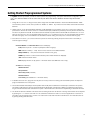
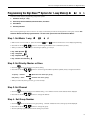
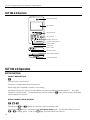
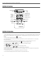
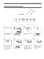
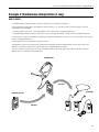
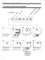
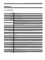
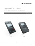
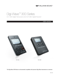
Digi-Wave™ 2.0
DLT 100 2.0 Digital Transceiver and DLR 60 2.0 Digital Receiver
USER MANUAL
DLT 100 2.0
DLR 60 2.0
MAN 153G
DLT 100 2.0 Digital Transceiver and DLR 60 2.0 Digital Receiver
Digi-Wave™
DLT 100 2.0 Digital Transceiver and DLR 60 2.0 Digital Receiver
Contents
Digi-Wave™............................................................................................................................................................................. 2
DLT 100 2.0 Digital Transceiver and DLR 60 2.0 Digital Receiver ...................................................................................... 2
System Overview...................................................................................................................................................................... 4
Getting Started: Preprogrammed Systems............................................................................................................................... 5
Before Programming the Digi-Wave™ System.......................................................................................................................... 6
Programming the Digi-Wave™ System for 2-way Mode........................................................................................................... 8
Programming the Digi-Wave™ System for 1-way Mode(s)........................................................................................................ 9
Programming the Digi-Wave™ System: DLT 100 2.0 Optional Settings.................................................................................. 10
DLT 100 2.0 Controls............................................................................................................................................................. 12
DLT 100 2.0 Operation........................................................................................................................................................... 12
Button Functions............................................................................................................................................................. 12
DLR 60 2.0 Controls............................................................................................................................................................... 14
DLR 60 2.0 Operation............................................................................................................................................................ 14
Example 1: 2-way Mode, Tour Guide..................................................................................................................................... 15
How it works................................................................................................................................................................... 15
Example 1: 2-way Mode, Tour Guide (continued)................................................................................................................... 16
How it works (CONTINUED)............................................................................................................................................ 16
2-Way Setup for Tour Guide Operation................................................................................................................................... 17
2-WAY MODES.............................................................................................................................................................. 17
2-Way Setup for Tour Guide Operation (continued)................................................................................................................. 18
Example 2: Simultaneous Interpretation (1-way)..................................................................................................................... 19
How it works................................................................................................................................................................... 19
1-way Setup for Simultaneous Interpretation.......................................................................................................................... 20
1-WAY MODES.............................................................................................................................................................. 20
1-way Setup for Simultaneous Interpretation.......................................................................................................................... 21
IMPORTANT................................................................................................................................................................... 21
Repeater Mode...................................................................................................................................................................... 22
Differences between DLT 100 2.0 and DLT 100...................................................................................................................... 23
Differences between DLR 60 2.0 and DLR 60........................................................................................................................ 24
Differences between DLT 100 and DLT 100 2.0 firmware versions.......................................................................................... 24
Specifications......................................................................................................................................................................... 25
DLT 100 2.0 Transceiver.................................................................................................................................................. 25
Specifications......................................................................................................................................................................... 26
DLR 60 2.0 Receiver....................................................................................................................................................... 26
Troubleshooting...................................................................................................................................................................... 27
2
DLT 100 2.0 Digital Transceiver and DLR 60 2.0 Digital Receiver
FAQs...................................................................................................................................................................................... 28
FCC statements..................................................................................................................................................................... 29
2-year Warranty...................................................................................................................................................................... 30
Notes..................................................................................................................................................................................... 31
Hearing Safety
CAUTION!
This product is designed to amplify sounds to a high volume level which could potentially cause hearing damage if used
improperly. To protect your hearing and the hearing of others:
(1) Turn the volume down before putting on the earphone or headphone, and then adjust the volume to a comfortable level,
(2) Set the volume level at the minimum setting that you need to hear,
(3) if you experience feedback (a squealing or howling sound), reduce the volume setting and move the microphone away from the
earphone or headphone, and (4) Do not allow children or other unauthorized persons to have access to this product
Medical Device Safety
CAUTION!
1. Before using this product with an implantable or other medical device, consult your physician or the manufacturer of your
implantable or other medical device.
2. If you have a pacemaker or other medical device, make sure that you are using this product in accordance with safety
guidelines established by your physician or the implantable device manufacturer.
RECYCLING INSTRUCTIONS
Battery Safety and Disposal
Help Williams Sound protect the environment! Please take time to dispose of your equipment properly. Please do NOT
dispose of batteries in the household trash. Please take the batteries to a retail or community collection point for recycling.
Product Recycling:
Please do NOT dispose of your Williams Sound equipment in the household trash. Please take the equipment to an
electronics recycling center or return the product to the factory for proper disposal.
3
DLT 100 2.0 Digital Transceiver and DLR 60 2.0 Digital Receiver
System Overview
The Digi-wave™ system is a patented, digital spread-spectrum (DSS), simultaneous two-way wireless listening system
operating in the 2.4 GHz band. Due to it’s frequency-hopping algorithm, it avoids interference and is a very secure method of
communication. For a more detailed explanation of how Digi-wave technology works, please visit our website and download the
“Digi-wave™ Technology White Paper” (under “Support – Downloads - Tech Bulletins”).
A Digiwave communication system consists of at least one DLT 100 2.0 and various combinations of DLT 100 2.0’s and DLR 60
2.0’s depending on the venue.
The DLT 100 2.0 is a 2-way transceiver, meaning that it can transmit and receive audio simultaneously. It can operate in one of 3
different modes:
1.In Two-way Mode, a speaker (with a DLT 100 2.0) can hear another speaker’s voice (from a second DLT 100 2.0)
and, at the same time, can also transmit their own voice. In this way, two-way communication is established (similar to
a phone conversation). Two-way mode can only be established between DLT 100 2.0 units. In addition, DLR 60 2.0
receivers in the same group can also hear the broadcast.
2.In One-way Mode, one DLT 100 2.0 acts as a transmitter (speaker) and another DLT 100 2.0 acts as a receiver
(listener). In addition, DLR 60 2.0 receivers in the same group can also hear the broadcast. There are 4 one-way
modes.
3.In Signal Repeater Mode, the DLT 100 2.0 receives audio from another DLT 100 2.0 and re-broadcasts the signal
to increase the transmitted range of the person speaking. In this way, larger groups can be covered by using one
or more DLT 100 2.0’s acting as repeaters. Listeners can have either DLT 100 2.0’s or DLR 60 2.0’s to listen to the
broadcast.
The DLR 60 2.0 is a receiver only. Users of receivers can only hear what is being broadcast by DLT(s).
Combinations of one or more DLT 100 2.0’s and DLR 60 2.0’s in One-way mode, Two-way mode, or Repeater mode can be used
to facilitate different events, depending on what needs to be spoken and what needs to be heard. Examples of scenarios will be
covered here.
Typical Scenarios include:
Guided Tours - with one or more tour guides (2-way), with audience participation (2-way), or without audience participation (1-way)
Language Interpretation - one or more interpreted languages transmitted to audience (1-way)
Note: there are many more scenarios than are covered in this manual, however these would be variations on the ones discussed
here. Rules of Operation for 1-way or 2-way mode must be followed for successful operation.
4
DLT 100 2.0 Digital Transceiver and DLR 60 2.0 Digital Receiver
Getting Started: Preprogrammed Systems
If a system has been purchased, you will not need to perform any programming. The system will have been configured to your
order. Turn chairman master on first so other units can pair. Slave units will turn off after 5 minutes if they cannot find a
master.
1. Charge all DLT 100 2.0’s. If using DLR 60’s, either charge them with NiMH batteries or insert fresh Alkaline batteries. Make
sure the battery switch is in the correct position for “Alkaline” or “NiMH”. Any DLR 60 2.0’s that will be used should have fresh
batteries.
2. Identify and turn on the Chairman Master (CM) first, usually identified by a grey silicone cover. Turn on the DLT by holding the
power button until the LCD screen comes on. If Chairman Slave (CS) or Slaves are powered up first they will turn off after a few
minutes if not paired with the CM. As Chairman Slave and Slaves are paired with the CM the CM and CS will show C-#. The #
refers to how many DLT 100 2.0’s are paired within the group, i.e. C-12 means that 12 DLT 100 2.0’s are paired with the CM or
CS within their group. This can be utilized as an attendance checker making sure everyone is connected with the group.
3. Once all the DLT’s are on, you can check the set-up status of all units by pressing the power/menu button momentarily to
scroll through the settings:
Chairman Master and Chairman Slave screens will display:
C-6 (Chairman plus six = number of participants within the group).
ADD Address number (0 – 1023). Each DLT must have its own individual address.
Group number (0 – 1023) must be the same number for the group.
CODE Only shows if a code has been entered (code number will NOT be displayed).
“F-#” Denotes software version.
Time Displays the time of day. (Note: F-7 firmware version does not have Time of Day).
All Slave units will display:
Address Number
Group Number
Secure Key Code (if entered)
Software Version
Time of Day (Not available on F-7 firmware version)
4. If headsets are to be worn, plug them into the jacks on the top of the DLT’s making sure that the Microphone and Earphone
plugs are inserted into the correct jacks.
5. The Chairman Master will usually be the first speaker and should press the talk button momentarily to activate the microphone.
This will be confirmed by the red LED around the talk button illuminated. If the talk LED is flashing, the talk button was held too
long and the talk mute has been activated in the system. Hold the talk button until the LED’s stop flashing to deactivate talk mute.
6. The Chairman Slave and all Slave units should now be hearing audio from the CM unit. Listening volume levels can be adjusted
by pressing the – or + button. One other DLT can activate the Talk button for team tour or teach applications. A maximum of
two talkers can be activated at any one time. For a Slave unit to talk, either the CM or CS will have to turn their talk button off
by quickly pressing their talk button.
5
DLT 100 2.0 Digital Transceiver and DLR 60 2.0 Digital Receiver
Before Programming the Digi-Wave™ System
Prior to programming the system, decide what mode you will need, and what priority each DLT will have.
Any two people can talk in a group at any given time. The CM will have first priority, CS has second priority and Slave units have
third priority. The CM or CS will have to turn off their talk access to allow the Slave units to talk. When two people are talking in a
group the participants can hear both voices in the DLT’s or DLR’s.
The CM and CS have the ability to lock out other talkers by holding down the TALK button for three seconds. All system TALK
LEDs will continuously flash while other participants are locked out of the TALK feature.
1. Decide which mode you need.
A. 2-Way Mode
In 2-way mode, DLTs can hear and talk to each other, just like having a phone conversation or a conference call. DLRs can listen
to the conversation. Common applications include: Tours with multiple Tour Guides, Tours with audience participation (Q&A),
Wireless Intercomm, Portable Discussion and Personal Communication.
Rules of Operation (2-way mode)
The following rules must be followed. Failure to adhere to these rules will result in unpredictable, unsupported operation.
2-Way
There must be one, and only one Chairman Master (CM) per group.
If the CM unit is off, the Chairman Slave and Slave units will turn off after a few minutes.
Chairman Slave is optional and there can only be one per group.
Each DLT 100 2.0 must have its own address and the address cannot be duplicated within a group.
Maximum two Talkers can operate simultaneously within a group.
Maximum four Groups can operate simultaneously within the same area, but each group must be assigned its own group number.
When using four simultaneous groups, group numbers must be sequential. i.e. 11, 12, 13, 14. Any numbers 0-1023 can be used.
Attendee count will only work with addresses 1-99 (Maximum 100 DLT 100 2.0’s with one Master at address 0).
With Secure Key Code active, all DLT 100 2.0’s within the group must have the same 4-digit code entered. (DLR 60s/DLR 50s will
not work with secured DLTs)
B. 1-WAY MODE(S)
In 1-way mode, DLTs listen to a speaker using a DLT, but they cannot communicate back to that speaker - instead they
communicate to DLRs. The most common applications are: Simultaneous Interpretation with one or more interpreters, or Tours
without audience participation (no Q&A).
There are (4) 1-way Modes:
1-way - Main Speaker
1-way - Interpreter
1-way - Repeater Mode
1-way - Receive or Listen Only
(Not available on firmware version F-7)
Rules of Operation (1-WAY MODES)
The following rules must be followed when setting up any Digi-Wave™ system. Failure to adhere to these rules will result in
unpredictable, unsupported operation.
Up to 15 channels can be used simultaneously, i.e. one floor and 14 interpreters.
6
DLT 100 2.0 Digital Transceiver and DLR 60 2.0 Digital Receiver
There must be one Master (usually this is also the floor), and only one, per group.
Each Interpreter must be assigned their own channel number.
Repeater function can only be used in 1-Way mode.
When repeater function is used, all 15 channels can be utilized in one-way mode, i.e. one floor and 14 interpreters.
When repeaters are used, Floor (channel 0) must be assigned as the master unit for the group. All other DLT’s have to be
assigned as “SLV”.
2. Decide Speaking Priority for each DLT.
There are 3 levels of priority (see below).
Any two people can talk in a group at any given time. The CM will have first priority, CS has second priority and Slave units have
third priority. The CM or CS will have to turn off their talk access to allow the Slave units to talk. When two people are talking in a
group the participants can hear both voices in the DLT’s or DLR’s.
The CM and CS have the ability to lock out other talkers by holding down the TALK button for three seconds. All system TALK
LEDs will continuously flash while other participants are locked out of the TALK feature. The Chairman Master can override anyone
else talking within the group. Chairman Slave has talking priority over Slaves.
Speaker priority is assigned as follows:
1st priority — Chairman Master ( CM )
2nd priority — Chairman Slave ( CS )
3rd priority — Slave ( SLV )
3. Decide what Address(es) you will need.
Each transceiver and receiver must have a unique address. Refer to the “Rules of Operation” to determine how you will address
the units.
4. Decide what Group(s) you need.
Refer to the “Rules of Operation” in this section (1. B.) to figure out which groups you need for the mode you have chosen.
7
DLT 100 2.0 Digital Transceiver and DLR 60 2.0 Digital Receiver
Programming the Digi-Wave™ System for 2-way Mode
There are 4 basic steps to programming a Digi-wave system:
1. Set Mode: 2-way or 1-way
2. Set Priority: Chairman Master, Chairman Slave, and Slave
3. Set Address
4. Set Group Number
Most of the programming is done on the DLT 100 2.0(s); the receivers just need to be assigned the correct group number. The
Chairman Master should be programmed first - all other units sychronize with the Chairman Master.
Step 1. Set Mode: 2-way
a. With the DLT 100 2.0 turned on, press and hold the
b. Use either of the the
and
buttons until the icons on the display begin flashing.
buttons to scroll through the different icon combinations (modes).
c. When you reach 2-way mode, both icons will be flashing alternately
. Go to step 2.
Step 2. Set Priority: Chairman Master, Chairman Slave, and Slave
a. Push the
button to advance to the priority setting.
b. Use either of the the
buttons to scroll through the different priorities. Speaker priority is assigned as follows:
1st priority — Chairman Master ( CM )
2nd priority — Chairman Slave ( CS )
3rd priority — Slave ( SLV )
(Must have one per group)
(Optional)
(All other units in the same group)
c. When you reach the priority you want, go to the next step.
Step 3. Set Address
a. Push the
button to advance to the address setting. “ADD” will flash and the current address will be displayed.
b. Use either of the the
buttons to change the address.
c. Each unit must have a different (unique) address assigned.
Step 4. Set Group Number
a. Push the
button to advance to the group setting. “GROUP” will flash and the current group will be displayed.
b. Use either of the the
buttons to change the group.
c. All units operating together should have the same group number.
8
DLT 100 2.0 Digital Transceiver and DLR 60 2.0 Digital Receiver
Programming the Digi-Wave™ System for 1-way Mode(s)
There are 4 basic steps to programming a Digi-wave system:
1. Set Mode: 2-way or 1-way
2. Set Priority: Chairman Master, Chairman Slave, and Slave
3. Set Address
4. Set Group Number
Most of the programming is done on the DLT 100 2.0(s); the receivers just need to be assigned the correct group number. The
Chairman Master should be programmed first - all other units synchronize with the Chairman Master.
Step 1. Set Mode: 1-way
a. With the DLT 100 2.0 turned on, press and hold the
b. Use either of the the
and
buttons until the icons on the display begin flashing.
buttons to scroll through the different icon combinations (modes).
c. When you reach the 1-way mode you are looking for (below), go to step 2.
1-way - Main Speaker
1-way - Interpreter
1-way - Repeater Mode
1-way - Receive or Listen Only
Step 2. Set Priority: Master or Slave
a. Push the
button to advance to the priority setting.
b. Use either of the the
buttons to scroll through the different priorities. Speaker priority is assigned as follows:
1st priority — Master
(Must have one master per group)
2nd priority — Slave
(All other units in the group)
c. When you reach the priority you want, go to the next step.
Step 3. Set Channel
a. Push the
button to advance to the address setting. “CH” will flash and the current address will be displayed.
b. Use either of the the
buttons to change the address.
Step 4. Set Group Number
a. Push the
button to advance to the group setting. “GROUP” will flash and the current group will be displayed.
b. Use either of the the
buttons to change the group.
c. All units operating together should have the same group number.
9
DLT 100 2.0 Digital Transceiver and DLR 60 2.0 Digital Receiver
Programming the Digi-Wave™ System: DLT 100 2.0 Optional Settings
Secure Key Code:
When a group has been set up and the same Secure Code has been entered into all the DLT 100 2.0’s, the DLT 100 2.0’s
without this Secure Code entered cannot listen in on the group. This may be desirable in private or high security-level functions.
The same four digit code must be programmed into all of the DLT’s, Chairman Master, Chairman Slave and Slaves. If a different
secure code has been entered, participants cannot re-enter the group without re-entering the correct secure code. The only time
the Secure Code is displayed is when it is being entered. To block users from entering the set-up mode, refer to the Set-up
lock (SLOC) feature (below).
1. Choose a 4 digit numerical code; i.e. 1357. You must use the same code on each DLT in the group.
2. Start with the Chairman Master when programming.
3. With the DLT 100 2.0 turned on, hold the
4. Use the menu button
and
buttons simultaneously for two seconds to enter the set-up menu.
to scroll through the menu pages until you get to the screen displayed in figure 1.
5. The first dash will be blinking (figure 1); using the
6. Press the menu button
Figure 1
button, enter first digit of the code (0 – 9).
again to move to the second dash which will now be blinking.
7. Enter the next digit and continue until all four digits have been entered.
8. One more press of the menu button
and you will see the word CodE displayed (figure 2).
9. With the Secure Key Code entered, exit the set-up menu by holding the
simultaneously for two seconds.
and
buttons
A147
Figure 2
10. Follow the same process with the Chairman Slave and Slave units.
NOTE: There will be fewer pages to scroll through on the Chairman Slave and Slave units to get to the code
set-up screen.
SET-Up Lock (SLOC)
A149
Set-up Lock enables the Administrator to prevent unauthorized changes to the system set-up.
NOTE: Each DLT 100 2.0 has to be locked and unlocked individually.
1. Press
twice, then
twice (^-^-v-v). This has to be done within 5 seconds. ‘SLOC’ will appear
momentarily on the screen (figure 3). SLOC is now enabled.
Figure 3
2. When SLOC is enabled, if a user tries to change any setting by entering the set-up mode, ‘SLOC’ will
appear momentarily on the screen. See figure 3.
3. To unlock this feature, the same (^-^-v-v) sequence must be entered. There will be no prompt showing
that SLOC was disabled. Accessing the set-up mode is the indication that SLOC is disabled.
A148
NOTE: Each DLT 100 2.0 has to be locked and unlocked individually.
Attendee Checking
When the Master Chairman presses the MENU button once, the number of SLAVE devices connected to the system will be
displayed for two seconds. Addresses 0 - 99 must be used for attendee checking feature. Addresses over 99 will not be
registered. ie: C 12 = 12 DLT’s synched with CM
Tone Control
1. With the DLT 100 2.0 powered ON, press and hold the – and + buttons
simultaneously for 2 seconds.
2. The LCD will display the last tone setting t: (1 - 9). See Figure 4.
3. Using the -/+ buttons
, adjust the tone up or down.
1 = Most bass response
5 = Flat (Default)
9 = Most treble response
4. Press and hold the – and + buttons
10
Figure 4
simultaneously for two seconds to save the tone setting.
A146
DLT 100 2.0 Digital Transceiver and DLR 60 2.0 Digital Receiver
Address Confirmation
Press the MENU button twice for the CM and CS, once for SLVs. The address for the DLT 100 2.0 will be displayed for two
seconds.
NOTE: Every DLT 100 2.0 MUST have its own address and all must be assigned to the same group.
Quick Group Change
“Groups” apply to 2-way Mode only.
until the GROUP indicator on the
1. With the DLT 100 2.0 powered ON, push and hold the Group button
screen starts blinking and the light above the Group button comes on (Figure 5).
2. Change groups by pushing the Up button
or the Down button
. If no buttons are pushed, the
Quick Group Change feature will time out after 5 seconds.
3. Push the Group button
once to exit the Quick Group Change function, or wait for 5 seconds.
Figure 5
A474
Push-to-Talk (Ptt) and Push-and-Latch (PNL)
This feature allows the user to choose between Push and Latch (PnL) or Push to Talk (Ptt). The default is PnL.
In PnL mode, when the TALK button
pressed and released again.
is pressed and released, it stays in talk mode until the TALK button is
Figure 6
In Ptt mode, the TALK button must be held down while speaking, and when released, it shuts off.
The DLT 100 2.0 must be set up as a Slave unit, in 2-way mode, prior to performing these steps.
1. With the DLT 100 2.0 powered ON, press and hold the Up button
simultaneously for 2 seconds to enter programming mode.
and the Down button
2. Push the Power/Menu button until the TALK indicator is flashing and either “PnL” is or “Ptt” is displayed.
(Figure 6).
3. Use either of the -/+ buttons
4. Press and hold the Up button
programming mode.
to switch between “PnL” and “Ptt”
and the Down button
simultaneously for 2 seconds to exit
A473
Side Tone Adjustment
This gives the user the ability to change the volume of their own voice heard in the headset (side tone).
1. With the DLT 100 2.0 powered ON, press and hold the Up button
simultaneously for 2 seconds to enter programming mode.
and the Down button
Figure 7
2. Push the Power/Menu button until “St:” is displayed. See Figure 7.
3. Use either of the -/+ buttons
4. Press and hold the Up button
programming mode.
to choose between Stt:0 (Off), St:1 (-6dB) (default), or St:2 (-12dB).
and the Down button
simultaneously for 2 seconds to exit
A472
Talk “Off” Double-Beep Indication Limit
The user hears an audible “double-beep” sound when the TALK button is turned off. This is heard in the headset of the user only; it
is not transmitted. On the DLT 100 2.0, as the headset volume is increased, the beep volume will increase until the headset volume
reaches 37, then the beep volume will stop increasing. (Note: On the DLT 100 the beep volume continued to get louder as the
headphone volume was increased, with no limit.)
11
DLT 100 2.0 Digital Transceiver and DLR 60 2.0 Digital Receiver
DLT 100 2.0 Controls
INTERNAL SPEAKER
LCD DISPLAY
LED INDICATORS
TALK BUTTON
VOLUME / SELECT UP
VOLUME / SELECT DOWN
POWER / MENU
HEADPHONE
JACK 3.5 MM
MIC JACK 3.5 MM
INTERNAL MICROPHONE
30-PIN CONNECTOR
A468
DLT 100 2.0 Operation
Button Functions
POWER / MENU BUTTON
·· Press and hold for power On/Off
·· Press once to change section when in setup menu
·· Review setup (push repeatedly to advance to next setting)
·· Attendance checking can only be done with a Master unit. Must have address assigned between 1 — 99 to allow
attendance checking function. To check attendance, push and release the
button and the number of attendees
will be displayed for 2 seconds.
GROUP CHANGE / SETUP BUTTONS
·· Press and hold
and
together for 3 seconds to enter or exit setup menu
·· Press and hold
button for 3 seconds to enter quick group change mode. The GRP light will flash. Then use
or
to change groups. To exit, push
again or just wait until the unit times out.
12
DLT 100 2.0 Digital Transceiver and DLR 60 2.0 Digital Receiver
·· Use these buttons to select channels in simultaneous interpretation mode
··
QUICK GROUP CHANGE / SETUP BUTTONS
·· Press and hold
and
together for 3 seconds to enter or exit setup menu
·· Press and hold
button for 3 seconds to enter quick group change mode. The GRP light will flash. Then use
or
to change groups. To exit, push
again or just wait until the unit times out.
·· Use these buttons to select channels in simultaneous interpretation mode
MICROPHONE LEVEL ADJUSTMENT
·· Hold the
button for two seconds to enter mic level adjustment. For level adjustment use
or
VOLUME CONTROL / SELECT BUTTON
·· Control / Volume
·· Use to navigate selections in setup menu.
·· Access and adjust tone control (0-53)
TALK BUTTON
·· Press button momentarily once to activate the microphone. Press button once more to turn off the microphone
·· P
ress and hold the button for approximately 2 seconds to mute other DLT 100 2.0 slave units. Only the CM and CS have this
function.
([TALK] LED will blink on all units when in mute mode).
Battery Charging – DLT 100 2.0
1. This Product uses an internal rechargeable Lithium Polymer battery.
2. U
se the 30 Pin connector, located on the bottom of DLT 100 2.0 to charge the battery. Full charging time is approximately
5 hours. The Red LED flashes while charging. The Green LED will be on steady when the battery is charged.
3. Battery Maintenance - Charge the battery at room temperature.
13
DLT 100 2.0 Digital Transceiver and DLR 60 2.0 Digital Receiver
DLR 60 2.0 Controls
HEADPHONE
JACK
LANYARD
SLOT
STRENGTH DLT#1
STRENGTH DLT#2
ANTENNA
SYMBOL
NUMERIC TYPE
BATTERY
STRENGTH
NUMERIC DISPLAY
RED LED
GREEN LED
VOLUME
ADJUST
CH/GROUP
CHANGE
POWER
DOCKING
CONNECTOR
DLR 60 2.0 Operation
SPEAKER
1. Insert 2 AAA batteries into the DLR. Be sure to observe correct polarity. You can use either Alkaline or NiMH, but make sure the
battery switch is in the NiMH position to charge NiMH batteries. If Alkaline batteries are used, put the battery switch in the ALK
position.
2. Power on/off by holding the power button
for 3 seconds.
3. In 1-way mode, the DLR will seek active DLT’s; press channel button up or down to seek next active DLT. In 2-way mode,
group must be selected.
4. The Antenna Symbol will flash, and there will be no Signal Strength Bars, if not synchronized with a DLT 100 2.0.
5. If the units are synchronized, briefly push the power button
6. To change group, hold the
7. Use
or
8. Hold
and
and
to show group assigned (0 to 99).
buttons for 3 seconds until “GROUP” is flashing.
buttons to select group number.
buttons for 3 seconds again to save the group number.
9. To change volume level press
or
buttons, display will show 00 through 30.
10. User can listen using the speaker on the back of the DLR or by plugging in stereo or mono earphones into the jack (which
defeats the speaker operation).
11. Low battery indicator will show as a blinking battery symbol with no bars inside it.
12. The DLR will automatically power down after 5 minutes if not synchronized with a DLT.
BATTERY TYPE
SWITCH
14
A467
DLT 100 2.0 Digital Transceiver and DLR 60 2.0 Digital Receiver
Example 1: 2-way Mode, Tour Guide
How it works
1. Tour Guide 1 speaks, using a DLT 100 2.0 alone (built-in mic) or using it with a compatible headset mic.
2. Each Tour Group Member and Tour Guide 2 listen directly to Tour Guide 1, each using a DLT 100 2.0 alone (built-in speaker) or
using it with a compatible headset mic.
3. Tour Guide 2 then speaks, using a DLT 100 2.0 alone (built-in mic) or using it with a compatible headset mic.
4. Each Tour Group Member and Tour Guide 1 listen directly to Tour Guide 2 using a DLT 100 2.0.
5. With the push of a button, a Tour Group Member uses a DLT 100 2.0 (built-in mic) to ask the Tour Guides a question. Both
Tour Guides and all Tour Group Members listen to the question, each using a DLT 100 2.0.
6. Tour Guide 2 responds to the question, using a DLT 100 2.0. Tour Guide 1 and all Tour Group Members listen to the answer,
each using a DLT 100 2.0.
7. With the push of a button, Tour Guide 1 takes control of the discussion once again and responds to the same Tour Group
Member question. Tour Guide 2 and Tour Group Members now listen to Tour Guide 1’s answer, each using a DLT 100 2.0.
8. Tour Guides have two-way communication capability; they can talk/listen simultaneously to one another. Tour Group Members
can participate as listen-only or can access two-way mode with the quick push of a button. Tour Guides always control the
discussion.
15
DLT 100 2.0 Digital Transceiver and DLR 60 2.0 Digital Receiver
Example 1: 2-way Mode, Tour Guide (continued)
How it works (CONTINUED)
TOUR GUIDE 1
TOUR GROUP
TOUR GUIDE 2
2-WAY
2-WAY
A259
16
DLT 100 2.0 Digital Transceiver and DLR 60 2.0 Digital Receiver
y
nl
O
ve
R
ec
ei
2W
ay
2-WAY MODES
2W
ay
(i.
e.
To
u
rG
ui
de
)
2-Way Setup for Tour Guide Operation
1
2
3
Press and hold POWER
button for 2 seconds to
turn DLT 100 2.0 on
Press
and
together for 3 seconds to
enter programming mode.
Mode icon will blink on the
LCD screen.
5
6
7
Press POWER / MENU
button to enter selected
Tour Guide mode (shown
above) and advance to the
next setting.
Use the
buttons
to select CHAIRMAN MAS,
CHAIRMAN SLV or SLV.
When mode selection is
made MAS (for example) will
blink (shown in screen 8).
There MUST be one Master
per group.
4
Use the
buttons to select 2-way
mode (shown in screen 5)
8
Press POWER / MENU
button to enter selected
Priority mode and advance
to the next setting.
17
DLT 100 2.0 Digital Transceiver and DLR 60 2.0 Digital Receiver
2-Way Setup for Tour Guide Operation (continued)
9
Address ( ADD ) icon will
now begin to blink. Use
the
buttons to
select a Address number (
0 – 1023 ).
10
button to enter
Press
Address number and move
to the next setting.
Note: Attendee count will
only work with addresses
1-99 (Maximum 100 DLT
100 2.0’s with one Master at
address 0).
13
If this is a slave unit, the
side-tone adjustment will be
displayed (not avail on CM
or CS). Use the
buttons to select a sidetone level ( 0 – 2 ).
14
Press
button to save
side-tone level and move to
the next setting.
18
The secure code screen
will now be displayed, with
the first character blinking.
Press
button to
advance to the next position.
18
GROUP icon will now
blink. Use the
buttons to select a Group
number. Must have one
Master in a group; and the
MAS and SLV units must
have same group number.
15
If this is a slave unit,
the Push-to-talk/Pushand-latch feature will
be displayed (not avail
on CM or CS). Use the
12
Press
button to
enter Group number and
move to the next setting.
For 4 simultaneous
groups, numbers must be
consecutive. ie ( 11, 12, 13,
14 ). Can use (0 - 1023) for
group numbers.
16
Press
button to save
the Ptt or PnL setting and
move to the next setting.
buttons to
select Ptt or PnL.
17
Use the
buttons
to select the first number (
0 – 9).
11
19
Repeat steps 17 and 18
until all numbers have been
entered. When the last
number has been entered,
nothing will be blinking.
20
Press
button to save
the secure keycode. You
are now at the beginning
of the programming. Press
and
together
for 3 seconds to exit
programming mode and
return to the main screen.
DLT 100 2.0 Digital Transceiver and DLR 60 2.0 Digital Receiver
Example 2: Simultaneous Interpretation (1-way)
How it works
1. The Main Speaker will use channel 0; Press the TALK button to activate the microphone
2. Each Interpreter unit will need to be assigned a channel number (1-14). The TALK button must be activated to send the
interpretation to the attendees.
3. The floor speaks, using a DLT 100 2.0 alone (built-in mic) or using it with a compatible headset mic.
4. Interpreter listens directly to the floor, using a DLT 100 2.0 alone (built-in speaker) or using it with a compatible headset mic.
5. With the push of a button, interpreter simultaneously interprets to the listeners, using a DLT 100 2.0 alone (built-in mic) or using
it with a compatible headset mic.
6. Each listener hears the interpretation using a DLR 60 2.0.
The Repeater Function can only be used in simultaneous interpretation mode. An additional DLT 100 2.0 can be set-up as a
repeater to increase the range of each channel. See section “Repeater Mode” for details.
The 3.5mm stereo microphone jack can accept a headphone level or a line level output from audio sources when using the
Williams Sound, LLC WCA 094 attenuated cable.
INTERPRETER
ONE-WAY
LISTENERS
SPEAKER (FLOOR)
ONE-WAY
A261
19
DLT 100 2.0 Digital Transceiver and DLR 60 2.0 Digital Receiver
re
te
r)
te
rp
(In
R
ec
ei
Sp
ea
k
ve
/S
pe
ak
y
O
nl
O
ve
R
ec
ei
R
ep
ea
te
r
1-WAY MODES
nl
y
(M
ai
n
Sp
ea
ke
r)
1-way Setup for Simultaneous Interpretation
1
2
3
Press and hold POWER
button for 2 seconds to
turn DLT 100 2.0 on.
Press
and
buttons together for
2 seconds to enter
programming mode.
Mode icon will blink on the
LCD screen.
5
6
7
8
Press POWER / MENU
button to save selected
interpretation mode and
advance to the next screen.
Now the SLV or MAS icon
will blink. (Receive only will
not have this option. Skip to
step 9).
Use the
buttons
to select SLV ( Slave ) or
MAS (Master).
Press POWER / MENU
button to save SLV or MAS
and advance to the next
screen.
20
is used, it
Note: When
must be defined as
Master, except when
repeater is used;
then Repeater must
be set to Master.
4
Use the
buttons to select
interpretation mode.
DLT 100 2.0 Digital Transceiver and DLR 60 2.0 Digital Receiver
1-way Setup for Simultaneous Interpretation
9
10
11
12
Channel icon will now begin
to blink Press ( + ) or ( - )
button to select a Channel
number 1 – 14. Transmitting
Channel must be set different.
( N/A with Main Speaker unit.
Set to CH 0 ).
Press POWER / MENU
button to enter Channel
number.
Group icon will now blink.
Press POWER / MENU
button to enter Group
number.
13
14
15
Press
button to save
side-tone level and move to
the next setting.
The secure code screen
will now be displayed, with
the first character blinking.
Side-tone adjustment will
be displayed. Use the
buttons to
select a side-tone level
(0– 2).
Press ( + ) or ( - ) button
to select a Group number.
Master and Slave units must
have same group number.
16
Press
button to
advance to the next position.
Use the
buttons
to select the first number (
0 – 9).
17
18
Repeat steps 17 and 18
until all numbers have been
entered. When the last
number has been entered,
nothing will be blinking.
You are now at the beginning
of the programming. Press
and
together for 3
seconds to exit programming
mode and return to the main
screen.
19
IMPORTANT
There can only be one master (floor) per group.
21
DLT 100 2.0 Digital Transceiver and DLR 60 2.0 Digital Receiver
Repeater Mode
An additional DLT 100 2.0 can be set-up as a repeater to increase the range of each channel. When repeater mode is used, the
main speaker’s DLT is no longer the master - the master (unit all others sync to) now becomes one of the slaves.
Main Speaker (Floor) DLT
Must be set to Main
Speaker, CH 0 and SLV.
Main Speaker (Floor)
DLT Repeater
Interpreter DLT’s
Must be set to Repeater, CH
0 and MAS. NOTE: For more
than one repeater, repeaters on
additional channels must be SLV.
Must be set to Interpreter,
CH 1 - 14, and SLV.
Interpreter Repeater DLT’s
Must be set to Repeater,
CH 1-14 and SLV.
DLT-100 2.0’s FOR FLOOR AND INTERPRETERS
A501
CH 0
Main speaker (floor)
CH 1
CH 2
CH 3...
CH 14
CH 3...
CH 14
SLAVE
CH 0
CH 1
MASTER
CH 0
CH 2
SLAVE REPEATERS
CH 1
CH 2
CH 3...
CH 14
DLT 100 2.0 [ LISTEN ONLY ] OR DLR 60 2.0
DLT 100 2.0 [ LISTEN ONLY ] OR DLR 60 2.0 MUST BE ON THE SAME GROUP. EACH LISTENER WOULD SELECT A DESIRED CHANNEL / LANGUAGE.
NOTE: WHEN REPEATERS ARE NOT REQUIRED, THE MAIN SPEAKER ( CH 0 ) WILL BE THE MASTER.
22
A502
DLT 100 2.0 Digital Transceiver and DLR 60 2.0 Digital Receiver
Differences between DLT 100 2.0 and DLT 100
Function/Description
DLT 100 2.0
DLT 100
SLOC
With settings locked, can ONLY adjust Power, Volume,
Talk
With settings locked, can adjust Power, Volume, Talk,
Tone, Mic level, and Group
Voting function
Disabled
Enabled
GRP button / ABS button
Labelled “GRP”
1-way mode: not functional
2-way mode: used to enable easy group change with
push-and-hold of this button
Labelled “ABS”
1-way mode: not functional
2-way mode: On Master, used to enable voting; on
Chairman Slave or Slave, used to “Abstain” when
voting
Labelled “^”
1-way mode: Channel up
2-way mode: Group up
Labelled “yes”
1-way mode: Channel up
2-way mode: Group up
v button / no “ch-” button
Labelled “v”
1-way mode: Channel down
2-way mode: Group down
Labelled “no”
1-way mode: Channel down
2-way mode: Group down
Listen only (1-way mode) function
Disabled, icon not shown
Enabled, icon shown
Speaker only (2-way mode)
function
Disabled, icon not shown
Enabled, icon shown
Group Number / Clock function
Icon “GROUP” and Group Number Displayed in place
of Clock on Main Screen
Clock Enabled on Main Screen and during CM Setup
Talk Timer function
Disabled, Group number displayed in place of Talk
Timer on Main Screen
Enabled
Push-to-Talk (Ptt) and Push-andlatch (PnL) functions
Available on Slave units only
Unavailable
Microphone Gain Max Level
53
63
Side Tone Adjustment
Enabled; St: 0=off, St:1=-6dB, St:2=-12dB.
Unavailable
Dock detected/Mic Disable
Enabled. The DLT 100 2.0 is compatible with a dock.
Unavailable. The DLT 100 is not compatible with a
dock.
Auto shutoff timing for Slave Units
5 min. (Same as DLR 60 2.0)
2 min.
Line Input Level Adjust
Available with push-and-hold of “^” button; eight levels
L:0 through L:7
Not available
Compatible with Digi-Wave Dock
Yes
No
^ button / yes “ch+” button
23
DLT 100 2.0 Digital Transceiver and DLR 60 2.0 Digital Receiver
Differences between DLR 60 2.0 and DLR 60
Between 08/13 and 11/13, a limited number of DLR 60’s were manufactured and sold to the marketplace. If the front of the unit
says “Digi·WAVE”, you have a DLR 60. If it says “DIGI·WAVE 2.0”, you have a DLR 60 2.0. Most units are the DLR 60 2.0, so this
section may not apply to your product.
Function/Description
DLR 60 2.0
DLR 60
Change Group
Through Menu or Quick Group Change
Through Menu only
^ button / ch+ button
Labelled “^”
1-way mode: Channel up
2-way mode: Group up
Labelled “ch+”
1-way mode: Channel up
v button / ch- button
Labelled “v”
1-way mode: Channel down
2-way mode: Group down
Labelled “ch-”
1-way mode: Channel down
Dock detected/Mic Disable
Enabled. The DLR 60 2.0 is compatible with
a dock.
Unavailable. The DLR 60 is not compatible
with a dock.
Auto shutoff timing for Slave Units
not synced to a Master unit
5 min. (Same as DLT 100 2.0)
2 Min.
Compatible with Digi-Wave Dock
Yes
No
Differences between DLT 100 and DLT 100 2.0 firmware versions
Just prior to the release of Digiwave 2.0, DLT 100 units ran on firmware version F-6. With the release of the DLT 100 2.0, all units
shipped with a new firmware Version 7. Version 8 will be released sometime in 2014. With the DLT 100 2.0 powered on, check
the firmware version you have by pushing the power/menu key repeatedly until you see “F-X” where X could be 6, 7 or 8. The
features included in each of these versions are shown in the chart below.
Function/Description
F-6 (DLT 100)
Quick Group Change
F-8 (DLT 100 2.0)
√
√
Voting Function
√
Receive Only (1-way mode)
√
√
Speaker Only (2-way mode)
√
√
Clock Displayed on Main Screen
√
√
Group Number Displayed on Main Screen
Talk Timer
√
√
√
Push-to-Talk & Push-and-Latch (Ptt/PnL)
√
(slave units only)
(slave units only)
Mic Gain Default Level
36
33
33
Mic Gain Max Level
63
53
53
√
√
Line Level Input Control (for DigiWave Dock()
24
F-7 (DLT 100 2.0)
DLT 100 2.0 Digital Transceiver and DLR 60 2.0 Digital Receiver
Specifications
DLT 100 2.0 Transceiver
Dimensions
Weight
Color
Enclosure
Battery type
Battery life
Charge time
103 x 62 x 11mm (4.1 x 2.4 x 0.4 inches)
80g (2.8oz) including battery
Black and silver
Shatter resistant PC/ABS plastic
Li Polymer with smart charge built into transceiver
Up to 14hrs talk time per charge
5hrs. TFP 045 with cable and international adapters
Optional Chargers: Two-bay CHG 102, or 12-bay CHG 1012
Channels
Up to 15 simultaneous channels (Interpretation mode)
Up to 4 simultaneous groups (2 way mode)
Operating frequencies
Frequency response
S/N ratio
THD
Microphone input
2.4GHz (ISM band) 2.402 – 2.476GHz FHSS
150 – 11KHz
69dB (A weighted)
0.33 %
Internal microphone (disabled when MIC jack engaged) and 3.5mm stereo jack
(tip/sleeve) with electret microphone bias, adjustable gain with 63dB range.
Audio output
Range
Modulation
RF output
Max SSPL 90 111.8dB (EAR 013), 116.8dB (EAR 041) Internal speaker (disabled when ear jack engaged)
16mW @ 33Ω
Up to 100ft outdoors and 200ft indoors*
GFSK, binary CDMA
14dBm Max
Security
87 bit encryption, Secure Key Code, Setup Lock (SLOC)
Controls
Front panel push buttons for volume up/down, group select, menu access and selection, voting, timer, time,
MIC on/off, power on/off, tone control SLOC access and Secure Key access. System reset button (rear panel)
Output
Side tone
Speaker
Indicators
LED’s
Maximum presenters
3.5mm stereo/mono jack 30 pin charging jack with audio out to base stations
-12dB below volume, tone variation [ST:0 = Off, ST:1 = -6dB, ST:2 = -12dB]
Internal speaker (disabled when ear jack is engaged)
LCD (Group, channel, volume level, battery status, mode, signal strength)
(charge status, voting) Red LED around talk button when enabled. Amber LED signifying voting feature
activated.
Two presenters at any given time
Approvals
FCC, Industrie Canada, CE, C-tick, RoHS, WEEE
Warranty
2 years parts and labor (90 days on accessories)
25
DLT 100 2.0 Digital Transceiver and DLR 60 2.0 Digital Receiver
Specifications
DLR 60 2.0 Receiver
Dimensions:
Weight:
Frequency Band:
Modulation:
2.36” W x 3.54” H x 0.63” D
(60 mm x 90 mm x 16 mm)
1.7 oz. (47g) without batteries.
2.4 GHz (ISM band)
GFSK digital transmission
Range: Up to 100 ft outside, Up to 200 ft inside (depending upon environmental conditions)
Multi Channel: Up to 15 simultaneous channels (one way mode)
Case Material:
Black ABS Plastic
Battery Life: Alkaline Disposable (BAT 010-2): Up to 27 hrs
NiMH Rechargeable (BAT 022-2): Up to 21 hrs
Battery Type:
2 x AAA Alkaline or NiMH
Power Save:
Auto Sleep Mode after 1 min of no RF signal
Frequency Response:
S/N Ratio:
100 Hz – 11 kHz
65 dB (A-weighted)
THD: 0.1% (typical)
Antenna: Internal
Audio Output: 3.5 mm stereo jack with mono output for headphones, earphones, or neckloop
27 mW maximum @33Ω mono
Back Speaker (muted when headphone jack in use)
Controls:
Display:
Indicators:
Power, Volume +/-, Channel +/-, Setup, Battery Type
LCD shows status: Battery Level, RSSI, Group/Channel#
Red LED - blinks when charging
Green LED - stays on when charged
Docking Connector:
Compatible Transmitter:
30-pin iPod Style for charging and audio out
DLT 100 2.0, DLT 100
Temp. Range: 32° – 122°F (0° to 50°C)
Chargers:
Accessories:
Approvals:
Warranty:
26
CHG 102, CHG 1012, TFP 045
Silicone Skin, Lanyard, Wrist Strap
FCC, Industrie Canada, RoHS, CE, WEEE, C-tick
2 years, parts & labor
DLT 100 2.0 Digital Transceiver and DLR 60 2.0 Digital Receiver
Troubleshooting
PROBLEM
CAUSE
WHAT TO DO
Power does not turn-on
Dead battery
Charge the battery, replace battery
Power turned off
automatically
Master device can’t be found
Turn on Master unit
Power doesn’t turn off
Program Error
Press reset button on the back of device (DLT only)
Disconnection of headphone
Check headphone connection
Master unit shut off
Turn on / set master
Different Group Number settings
Set every unit to the same group number
Out of range
Move to within the range of 100ft (outside) or 200 ft
(inside) from the master unit
More than 1 master exists in a group
Set one master per group
Obstacle exists
Move to another place or move the obstacles
More than 2 units with same address exist in a group
Set different address
Error in attendee
checking
More than 2 units with same address exist in a group
Set different address
Unable to select receiving
channel
Transmitting channel is overlapping
Set different transmitting channel
Please check the mode for simultaneous interpretation
mode
Set simultaneous interpretation mode
More than 2 master units exist
Set one master only
Master unit shut off
Turn on / set master
Mic Sensitivity too low
See first, which microphone you have, and then adjust
the sensitivity accordingly. (i.e., Mic 044-2p is about
33, Mic 068 is about 17).
Master unit shut off
See why the Master shut off and correct the problem.
Turn on the Master and verify the battery level.
The microphone and
headphone will not work
Microphone and Headphone connections are
reversed
Verify first, then swap the connections.
The TALK button is
flashing
The talk button has been held down too long and the
system is now in “Talk Mute” mode.
Hold down the talk button until the talk button stops
flashing. This will disable talk mute.
Out of Range
Bring the unit closer to the master
Master is Off
Turn Master unit on
No 4-digit Secure Code, or Incorrect Code
Make the secure code the same as the master
Wrong Group Number
Make group numbers match the master
Group number above 100 (DLR 60 2.0)
Change all units to a group number under 100
“SLV” is blinking
The Slave has not found a Master to sync to.
Program at least one unit as the Master or turn on the
existing Master. Verify that the Group numbers match.
Time of Day Incorrect
Time of Day on Master is Incorrect. (All units sync
their time from the Master)
Set time of day to the correct time on the Master.
No audio in headphones
Unable to transmit
Interpretation
DLT 100 2.0 keeps turning
off
Can’t hear the speaker
A DLT 100 2.0 will not
sync to the Master
27
DLT 100 2.0 Digital Transceiver and DLR 60 2.0 Digital Receiver
FAQs
What is the range of the system?
Up to 100ft outdoors and up to 200ft indoors. (The range always depends on the environmental conditions).
What is the benefit of this system over the 72MHz systems?
DLT’s can operate in two way mode. Team teach/tour guide ability. Voting feature for discussion mode. Relay feature increases
range. Harmonized frequencies for international use.
How many simultaneous systems can be used?
Four systems in two way mode and one system in interpretation mode.
How many DLR’s can I use?
Unlimited within the range.
What is the battery life for the DLT and DLR?
DLT – up to 14hrs per charge.
DLR - up to 24hrs (2 x AAA Alkaline batteries) or 20hrs (2 x AAA NiMH batteries).
Is this product compatible with any other competitive system?
No.
Where can I buy this product?
Through Williams Sound dealers.
28
DLT 100 2.0 Digital Transceiver and DLR 60 2.0 Digital Receiver
FCC statements
Federal Communication Commission Interference Statement
This equipment has been tested and found to comply with the limits for a Class B digital device, pursuant to Part 15 of the FCC
Rules. These limits are designed to provide reasonable protection against harmful interference in a residential installation.
This equipment generates, uses and can radiate radio frequency energy and, if not installed and used in accordance with the
instructions, may cause harmful interference to radio communications. However, there is no guarantee that interference will not
occur in a particular installation. If this equipment does cause harmful interference to radio or television reception, which can be
determined by turning the equipment off and on, the user is encouraged to try to correct the interference by one of the following
measures:
·· Reorient or relocate the receiving antenna.
·· Increase the separation between the equipment and receiver.
·· Connect the equipment into an outlet on a circuit different from where the receiver is connected.
·· Consult the dealer or an experienced radio/TV technician for help.
FCC Caution
To assure continued compliance, any changes or modifications not expressly approved by the party responsible for compliance
could void the user’s authority to operate this equipment. (Example - use only shielded interface cables when connecting to
computer or peripheral devices).
FCC RF Radiation Exposure Statement
This equipment complies with FCC RF radiation exposure limits set forth for an uncontrolled environment. This equipment is a
handheld device and should be maintained with a minimum safety distance of 20cm from the antenna. This transmitter must not
be co-located or operated in conjunction with any other antenna or transmitter.
29
DLT 100 2.0 Digital Transceiver and DLR 60 2.0 Digital Receiver
2-year Warranty
Williams Sound products are engineered, designed, and manufactured under carefully controlled conditions to provide you with many
years of reliable service.
Williams Sound warrants the DLT 100 2.0 and DLR 60 2.0 against defects in materials and workmanship under normal use and
conditions for 2 years from date of purchase.
This warranty is available to the original end purchaser of the product and CAN BE transferred to subsequent purchasers of the
product.
Microphones, earphones, headphones, batteries, chargers, cables, carry cases, and most other accessory products carry a 90-day
warranty.
Williams Sound has no control over the conditions under which this product is used. Williams Sound, therefore, disclaims all warranties
not set forth above, both express and implied, with respect to the DLT 100 2.0 and DLR 60 2.0, including but not limited to, any
implied warranty of merchantability or fitness of use of such equipment including, without limitation, any warranty that the use of such
equipment for any purpose will comply with applicable laws and regulations.
Williams Sound shall not be liable to any person or entity for any medical expenses or any direct, incidental or consequential damages
caused by any use, defect, failure or malfunctioning of the product, whether a claim for such damages is based upon warranty,
contract, tort or otherwise, the sole remedy for any defect, failure or malfunction of the products is replacement of the product.
No person has any authority to bind Williams Sound to any representation or warranty with respect to the DLT 100 2.0 and DLR 60
2.0.
Unauthorized repairs or modifications will void the warranty. This warranty is void if damage occurred because of misuse, or if the
product has been repaired or modified by anyone other than a factory authorized service technician. Warranty does not cover normal
wear and tear on the product or any other physical damage unless the damage was the result of a manufacturing defect. Williams
Sound is not liable for consequential damages due to any failure of equipment to perform as intended. Williams Sound shall bear no
responsibility or obligation with respect to the manner of use of any equipment sold by it.
This warranty does not cover reimbursement for your costs of removing and transporting the product for warranty service evaluation or
installation of any replacement product provided under this warranty.
The exclusions and limitations set out above are not intended to, and should not be construed so as to contravene mandatory
provisions of applicable law. If any part or term of this Disclaimer of Warranty is held to be illegal, unenforceable, or in conflict with
applicable law by a court of competent jurisdiction, the validity of the remaining portions of this Disclaimer of Warranty shall not be
affected, and all rights and obligations shall be construed and enforced as if this Limited Warranty did not contain the particular part or
term held to be invalid. The terms of the warranty are governed by the laws of the State of Minnesota.
Prices and the specifications of the products are subject to change without notice.
*For Complete Warranty Statement go to: www.williamssound.com/warranty-statement
NOTICE: Williams Sound products are NOT designed for use in extreme temperature, humidity or chemical environments. The
introduction of chemicals such as chlorine, salt water or human sweat into the product will cause damage to the circuitry. Damage due
to these causes is NOT covered under the Product Warranty.
If you experience difficulty with your system, call Toll-Free for Customer Assistance 1-800-843-3544 (U.S.A.) or +1 952 943 2252
(Outside the U.S.A.)
If it is necessary to return the system for service, your Customer Service Representative will give you a Return Authorization Number
(RA) and shipping instructions.
30
DLT 100 2.0 Digital Transceiver and DLR 60 2.0 Digital Receiver
Notes
31
10300 Valley View Rd • Eden Prairie, MN 55344
800-328-6190 / 952-943-2252 • FAX: 952-943-2174
www.williamssound.com
©2014 Williams Sound • All Rights Reserved
MAN 153G