1
ООО "Техэнком"
Контрольно-измерительные приборы и оборудование
www.tehencom.com
Product Brochure
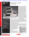
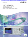
MG3700A
Vector Signal Generator
250 kHz to 3 GHz, 250 kHz to 6 GHz (Option)
Excellent Eco Product
ООО "Техэнком"
Контрольно-измерительные приборы и оборудование
www.tehencom.com
Supporting High-speed, Large-capacity,
and Wideband Wireless Communications
Wireless communications are evolving rapidly
towards high speed, large capacity and wide
bandwidth.
And next-generation wireless communications will
combine cellular phone service with wireless LAN
access.
The MG3700A Vector Signal Generator is based on a
160-MHz arbitrary waveform generator, including a
wide vector modulation bandwidth and largecapacity baseband memory.
The MG3700A supports digital modulation signals
for a wide range of wireless systems, supporting
evaluation of general-purpose mobile
communications, such as mobile phones as well as
wireless LANs.
Anritsu's IQproducer software can create waveform
data for transfer to the MG3700A via 100BASE-TX
Ethernet. In addition, IQ sample data files (ASCII)
created using general Electronic Design Automation
(EDA) tools such as MATLAB can also be converted
to waveform patterns for the MG3700A.
MATLAB® is a registered trademark of The MathWorks, Inc.
2
Product Brochure l
MG3700A
ООО "Техэнком"
Контрольно-измерительные приборы и оборудование
www.tehencom.com
Baseband waveform generator
Sample rate: 20 kHz to 160 MHz
ARB memory:
256 Msamples/ch (Standard)
512 Msamples/ch (Option)
Frequency Range 6 GHz
Modulation Bandwidth:
Large capacity
40 GB hard disk
BER Analyzer
Input bit rate: 1 kbps to 20 Mbps. (Standard)
100 bps to 120 Mbps. (Option)
■ Performance and Functions
■ Supports Various Communication Systems∗1
• Frequency Range
250 kHz to 3 GHz (Standard)
250 kHz to 6 GHz (Option)
• Wide Vector Modulation Bandwidth
120 MHz (Internal baseband generator)
150 MHz (External IQ input)
• High Level Accuracy
±0.5 dB (Absolute level accuracy)
±0.2 dB typical (Linearity)
• High-speed Waveform Transfer over 100BASE-TX Ethernet
• Built-in 40 GB Hard Disk
• Large-capacity Baseband Memory
1 GB = 256 Msamples/channel (Standard)
2 GB = 512 Msamples/channel (Option)
• Waveform Addition Function
Adds and outputs two signals, such as wanted signal +
interference signal or wanted signal + AWGN
• Built-in Standard 20-Mbps BERT Analyzer
1 kbps to 20 Mbps (Standard)
100 bps to 120 Mbps (Option)
• Waveform Patterns
Waveform patterns for communication systems bundled as
standard:
W-CDMA/HSDPA, GSM/EDGE, CDMA2000 1X/1xEV-DO
Wireless LAN (IEEE802.11a/b/g), PDC, PHS, AWGN,
Bluetooth , GPS, Digital Broadcast (ISDB-T1 segment, BS,
CS, CATV)
• Optional Waveform Patterns
Waveform patterns for the following communication
systems are offered as options:
TD-SCDMA
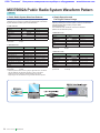
Public Radio System (RCR STD-39, ARIB STD-T61/T79/T86)
• IQproducer Waveform Generation Software
(Optional software license)
IQproducer is GUI-based PC application software for
changing parameters and generating waveform patterns in
compliance with the following system standards:
W-CDMA, AWGN, HSDPA/HSUPA∗2, TDMA∗2,
CDMA2000 1xEV-DO∗2, Multi-carrier∗2, Mobile WiMAX∗2,
DVB-T/H∗2, Fading∗2, Next generation PHS (XGP)∗2,
LTE FDD∗2, LTE TDD∗2
∗1: Read the MX370x Series Software Catalog for details.
∗2: A license key must be installed in the main frame.
• CDMA2000® is a registered trademark of the Telecommunications
Industry Association (TIA-USA).
• The Bluetooth ® mark and logos are owned by Bluetooth SIG, Inc.
and are used by Anritsu under license.
• WiMAX® is a trademark or registered trademark of WiMAX Forum.
• Other companies, product names and service names are
registered trademarks of their respective companies.
Product Brochure l
MG3700A
3
ООО "Техэнком"
Контрольно-измерительные приборы и оборудование
www.tehencom.com
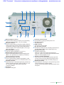
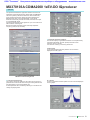
Easy-to-use Panel
Main PWR key
Switches power On/Off. When power is supplied, the lamp
lights green. The On lamp lights orange at power-on.
Hard Disk lamp
The lamp lights when the hard disk is being accessed.
[Panel Lock] key
Disables all key operations except [Main PWR] and [Local].
The key lamp lights red when the panel is locked.
Display Off/On key
Switches display On/Off. The key lamp lights red when
the display is off.
[Local] key
Disables remote control by GPIB and Ethernet and
allows local control only.
Remote lamp
Lights during remote control via GPIB and Ethernet.
[Preset] key
Initializes parameters.
Function Keys ([F1] to [F6] and [More])
Select and execute menu displayed on right of screen.
When there are two or more screens, additional pages
are displayed using the [More] key.
Function key group
Change modes for setting equipment main functions.
[Frequency]: Frequency setting mode
[Level]: Output level setting mode
[Baseband]: Baseband setting mode
[Utility]: Utility setting mode
Cursor/Edit key group
Select items or input numerical settings.
[Set]: Confirms selection
[Cancel]: Cancels selection
(The rotary encoder is disabled when the [Knob Hold]
key is pressed and the key lamp is on.)
4
Product Brochure l
MG3700A
CF Card slot
Slot for memory card for installing waveform patterns or
software, and for saving screen displays.
Keypad
[Shift]: Enables key functions described above keys in
blue letters when key lamp lit
[Numeric keys]: Input numeric settings
[Unit keys]: Set unit after numeric input
RF Output key group and connector
[Output]: Switches RF signal output On/Off. Key lamp is
lit when RF output is active
[MOD On/Off]: Turns modulation On/Off when RF signal
output is enabled. Key lamp is lit when signal modulation
is active
[RF Output connector]: RF signal output (N-J, 50 Ω)
Modulation Input connectors
Connectors for I/Q input signal when external baseband
signal is used for vector modulation (BNC-J, 50 Ω, Input
voltage range ±5 Vpeak).
Control Input connectors
Connectors for start trigger, frame trigger and pattern
trigger signals (BNC-J, TTL, reverse polarity of rising/
falling edges supported).
Ethernet jack (RJ45)
100BASE-TX connector for connecting PC via LAN when
using remote control or transferring waveform patterns.
When using this connector, jumper the two Ethernet
connectors on the rear panel using the supplied
straight-through LAN cable (Category 5).
Display
8.4-inch, 640 × 480 dots, color TFT LCD.
Screen dump saved to built-in hard disk or CF card as
color or gray-scale bitmap file.
ООО "Техэнком"
Контрольно-измерительные приборы и оборудование
Buffered Output connector
Outputs 10-MHz reference frequency for synchronizing
with other equipment (BNC-J, TTL, DC-coupled).
Ref Input connector
Input for external reference frequency signal (10 MHz or
5 MHz) when higher accuracy than the internal reference
can provide is required or when synchronizing with the
reference signal of other equipment (BNC-J, ≥0.7 Vp-p/
50 Ω, AC-coupled).
AUX Input/Output connectors
Output for marker signal (BNC-J 3 port, TTL).
Baseband Ref Clock Input connector
Input for clock signal reference for D/A sampling clock
(BNC-J, ≥0.7 Vp-p/50 Ω, AC-coupled, Input frequency
range from 20 kHz to 160 MHz).
Ext Pulse Mod Input connector
Input for external pulse modulation signal (BNC-J, 50 Ω,
Input voltage range from 0 to 5 V, Threshold of about 1 V).
IQ Output connector
Differential output of baseband signal (I/Q) generated by
arbitrary waveform generation function (D-Sub 15-J, 50
Ω). Converted to BNC using optional IQ Output
Conversion Adapter.
Cooling fan
Equipment cooling fan.
www.tehencom.com
Protective ground terminal
Ground when not using grounded power cord.
AC input connector
AC power input.
GPIB connector
For remote control by GPIB.
Ext. ALC Input connector
External DC voltage input for controlling output level (+3
to –8 dB, BNC-J, 600 Ω, Input voltage range ±5 V).
BER Input connectors
For BER measurements.
Enable TTL: BER measurement gate signal input
Clock TTL: Input for clock signal synchronized with data
Data TTL: Data input (BNC-J, TTL)
Junction connector (RJ45 jack)
When using the front-panel Ethernet jack, jumper this
Junction connector and the Ethernet jack above using
the supplied straight-through LAN cable (Category 5).
Ethernet jack (RJ45)
Ethernet jack for connecting PC when performing remote
control or transferring waveform pattern.
This jack can be used instead of the Ethernet jack on the
front panel.
Product Brochure l
MG3700A
5
ООО "Техэнком"
Контрольно-измерительные приборы и оборудование
www.tehencom.com
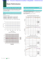
Basic Performance
Covers Frequency Range from 250 kHz to 6 GHz
Wide Vector Modulation Bandwidth
Choose a frequency range of either 250 kHz to 3 GHz (standard) or
250 kHz to 6 GHz (Option). The upper 6 GHz frequency is required
for supporting WLANs in the 5-GHz band and next-generation
communication systems.
120 MHz (Using internal baseband signal generator)
150 MHz (Using External IQ input)
High Level Accuracy
The excellent level accuracy assures a high overall measurement
accuracy.
Absolute level accuracy:
±0.5 dB typ (≥−120 dBm 25 MHz ≤ fc ≤ 3 GHz, E-ATT∗)
±0.8 dB typ (≥−120 dBm 3 GHz < fc ≤ 6 GHz, E-ATT∗)
±0.5 dB typ (≥−120 dBm 25 MHz ≤ fc ≤ 3 GHz, M-ATT∗)
±0.8 dB typ (≥−100 dBm 3 GHz < fc ≤ 6 GHz, M-ATT∗)
∗: E-ATT: Electronic attenuator, M-ATT: Mechanical attenuator
Frequency characteristic
Linearity
6
Product Brochure l
MG3700A
An RF modulation bandwidth of 120 MHz is available when using
internal baseband signal generation.
The modulation bandwidth of 150 MHz can be achieved when
using external IQ input.
Both bandwidths are supported up to 6 GHz.
ООО "Техэнком"
Контрольно-измерительные приборы и оборудование
SSB Phase Noise (25 MHz ≤ f ≤ 3 GHz)
(CW, Continuous mode: OFF, Frequency changing speed: Normal)
www.tehencom.com
SSB Phase Noise (3 GHz < f ≤ 6 GHz)
(CW, Continuous mode: OFF, Frequency changing speed: Normal)
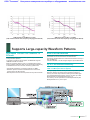
Supports Large-capacity Waveform Patterns
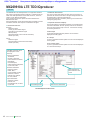
High-speed Transfer over 100BASE-TX
Ethernet
Wideband high-speed communication systems require transmission
of long waveform patterns.
To transfer long patterns at high speed, the MG3700A supports
100BASE-TX LAN connections.
When the waveform patterns of two or more MG3700A systems
must be updated, waveform data can be transferred simultaneously
to all MG3700A units over the LAN, shortening update times.
•H
igh-speed transmission of waveform patterns at 2 MB/s
•W
aveform patterns transferred to MG3700A from external PC
saved to built-in 40 GB hard disk
• Ethernet jacks on the front and rear panels for easy LAN connection
Built-in 40 GB Hard Disk
Various large-capacity waveform patterns and MG3700A
parameters can be saved the built-in 40 GB hard disk.
The transfer speed between the hard disk and waveform memory is
fast (14 MB/s typ).
If the hard disk fails, it can be changed using the optional HDD ASSY.
Up to 2 GB Waveform Memory
1 GB = 256 Msamples/channel (Standard)
2 GB = 512 Msamples/channel (Option)
The large-capacity waveform memory can save many waveform patterns.
Waveform patterns are read from the hard disk and saved to
memory for instant output without accessing the hard disk again.
The standard MG3700A waveform memory can save up to 256
Msamples/channel (128 Msamples/channel × 2).
This memory can be expanded to 512 Msamples/channel (256
Msamples/channel × 2) as an option.
Product Brochure l
MG3700A
7
ООО "Техэнком"
Контрольно-измерительные приборы и оборудование
www.tehencom.com
Useful Standard Functions
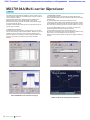
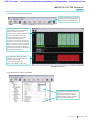
Waveform Combining Function
The MG3700A has two built-in arbitrary waveform memories, each
of which can hold one waveform pattern.
The MG3700A can output a signal from either memory, as well as
combine and output both signals simultaneously.
When measuring receiver characteristics, such as Adjacent
Channel Selectivity (ACS) or Blocking characteristics, one
MG3700A can output both the Wanted Signal and the Interfering
Signal or the Wanted Signal with AWGN.
Digital signal processing ensures excellent level accuracy.
Wanted Signal + AWGN Screen
Output Waveform Screen
Wanted Signal + Interference Signal Screen
Output Waveform Screen
Combination file
The Combination function makes the work of waveform addition
even easier. It uses a file in which various parameters, such as the
pattern file for the two waveform memories, the output level ratio,
and the offset frequency, are pre-defined.
When selected, the values for these parameters are automatically
set in the MG3700A.
Steps without Combination function
• Processing required waveform + interference waveform
• Set required waveform in memory A.
• Set interference waveform in memory B.
• Set level of required waveform.
• Set level of interference waveform.
• Set offset frequency of required and interference waveforms.
• Processing W-CDMA control CH + Data CH
• Set Control CH in memory A.
• Set Data CH in memory B.
• Set level of Control CH.
• Set level of Data CH.
8
Product Brochure l
MG3700A
Effect of Combination function
• Select the Combination file.
• Parameters are automatically set.
• Waveforms are ready to be generated.
ООО "Техэнком"
Контрольно-измерительные приборы и оборудование
www.tehencom.com
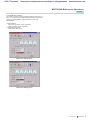
Sequence Mode
Built-in Standard 20 Mbps BER
The Sequence Mode Combination function saves operating
parameters, such as the waveform pattern repetition times,
waveform pattern switching, and output level settings, to a file.
Simply selecting this file performs these operations automatically.
This is very convenient when investigating state transitions in
response to received signals, such as during connection procedures.
The built-in BER analyzer supports easy BER measurement.
Input bit rate: 1 kbps to 20 Mbps
Measurable BER: 0 to 1%
A BER option supports measurement from 100 bps to 120 Mbps
(next page).
Steps without Sequence mode
•C
reate a single waveform pattern combining the required
waveform pattern type and times, and save it in memory.
•C
reate a new waveform pattern when the repetition time changes.
Effect of Sequence mode
The required waveform pattern and combination file are saved in
memory. Moreover, an external trigger can be used to repeat each
waveform pattern any number of times.
⇒ Makes efficient use of memory
⇒ Permits investigation of response status transitions
⇒ Enables manual sequence control
BER Measurement Screen
This function is used by connecting the signal demodulated by the
DUT to the Enable/Clock/Data BNC connectors on the rear panel.
In addition, up to 100 BER measurement results can be logged in a
file containing test information, including measurement time and date,
error rate, bit count, termination cause, and measurement mode.
Rear-panel Connectors
Count Mode
Time
Data Bit/Data
Error
Standard BER
Measurement Function
√
√
MG3700A-031/131
High speed BER Test Function
√
√
Note: T
he Time setting, available in the Standard Measurement
Function, is not available in the optional MG3700A-031/131
High-speed BER Test Function.
Product Brochure l
MG3700A
9
ООО "Техэнком"
Контрольно-измерительные приборы и оборудование
www.tehencom.com
Options
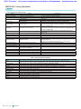
Comparison between Standard BER Measurement
Function and Option BER Measurement Function
Model: MG3700A-002
Name: Mechanical Attenuator
This option changes the standard electronic attenuator to a
mechanical attenuator, improving the maximum permissible
output level and distortion characteristics.
Settable range: –140 to +19 dBm
Accuracy range (CW): –140 to +10 dBm
Model: MG3700A-011
Name: Upper Frequency 6 GHz
This option extends the upper frequency to 6 GHz from 3 GHz.
Model: MG3700A-021
Name: ARB Memory Upgrade 512 Msamples
This option extends the memory capacity of the ARB unit to
256 Msamples/channel × 2 from 128 Msamples/channel × 2.
Standard BER
Measurement Function
(ver2.02 or later)
Model: MG3700A-001
Name: Rubidium Reference Oscillator
This option provides a 10 MHz reference signal VCO.
The frequency stability is better than the standard VCO.
Frequency: 10 MHz
Aging rate: ±1 × 10⁻¹⁰/month
Temperature stability: ±1 × 10⁻⁹ (0° to +50°C)
On/Off function of
Auto Resync
Time
Data Bit/
Data
Error
Measurement data
rate upper limit
SyncLoss count
function
Count
Mode∗
√
√
MG3700A-031/131
High-speed BER
Test Function
Hardware Options
Case
Can perform continuous measurement of high
error rates by changing measurement conditions to
match error rates.
√
Auto Resync = OFF is required for manufacturing
+ Threshold
inspection of some communications systems
adjustment
requiring reception sensitivity with BER=1%, and
for R&D applications that evaluate reception
sensitivity limits.
—
√
√
—
20
Mbps
√
120
Mbps
—
√
Measurement of
discontinuous PN
data
—
√
User pattern
measurement
—
√
Measurement range can be set.
This can be used for WLAN and next-generation
high-speed communications systems.
This can be used for continuous measurement
even when synchronization loss occurs.
When the size of continuous data such ISDB-T
PN23 exceeds the MG3700A memory capacity,
measurement can be performed by reducing the
memory requirements using discontinuous PN data.
This can be used for measuring fixed patterns such
as those specified by WiMAX.
∗: T
he measurement count of the standard BER measurement function (version 2.02 or earlier)
could be set as Time and Number of bits. The High-speed BER Test Function option does
not have the Time setting, and can set Number of bits and Number of error bits.
Model: MG3700A-031
Name: High-speed BER Test function
This option upgrades the standard built-in BER
measurement functions as follows:
• Increases the data rate to a range of 100 bps to 120 Mbps
• Added SyncLoss count function
• Added discontinuous PN data measurement function
• Added user pattern measurement function
Measurement System
10
Product Brochure l
MG3700A
ООО "Техэнком"
Контрольно-измерительные приборы и оборудование
www.tehencom.com
Software options: IQproducer License
The IQproducer software can be installed on any PC for evaluation
before purchase. To generate RF signals from the waveform
pattern created by the IQproducer software, the MG3700A must be
equipped with a license key for each of the technologies.
Model: MX370101A
Name: HSDPA/HSUPA IQproducer
Parameters can be changed and the required waveform
patterns can be generated for HSDPA Uplink/Downlink and
HSUPA E-DPDCH/EDPCCH.
Model: MX370102A
Name: TDMA IQproducer
Parameters can be changed and the required waveform
patterns can be generated for TDMA system signals. The
parameters that can be set include Modulation, Frame, Slot,
Data, and Filter.
Model: MX370103A
Name: CDMA2000 1xEV-DO IQproducer
Parameters can be changed and the required waveform
patterns can be generated for CDMA2000 1xEV-DO Forward/
Reverse signals.
Model: MX370104A
Name: Multi-carrier IQproducer
The MX370104A Multi-carrier IQproducer software is GUIdriven PC application software for creating multi-carrier
waveform patterns for the modulation and tone signals of
various communication systems.
There is also a function for converting two waveform patterns
with different sampling rates to a waveform pattern with one
sampling rate, as well as a function for creating a waveform
pattern with W-CDMA Downlink multi-carrier and clipping.
Model: MX370105A
Name: Mobile WiMAX IQproducer
Create UL and DL waveforms that comply with the IEEE
802.16e standard using a drop-and-drag GUI. Use these
files wherever a mobile WiMAX signal is required. Test
receivers per IEEE 802.16e standard section 8.4.13 Receiver Requirements (excluding the tests that require test
equipment other than a Signal Generator).
Model: MX370106A
Name: DVB-T/H IQproducer
The parameters for the ETSI EN 300 744 V1.5.1 (2004-11)
Physical Layer specification are set and a waveform pattern
is generated. A video file waveform pattern is generated by
reading the user’s MPEG-2 TS file. The generated
waveform pattern can be used for the receiver sensitivity
test using BER measurement and for the final operation
check using the video.
Model: MX370107A
Name: Fading IQproducer
The MX370107A Fading IQproducer supports generation of
faded waveform patterns (fading of each IQ channel,
calculation of correlation line, addition of AWGN) by reading
waveform patterns for the MG3700A.
Waveform patterns created by another IQproducer or IQ
data (ASCII) created by general simulation tools can be
selected as the input file.
The Channel Configuration can be selected from 1x1 SISO,
2x1 MISO, 1x2 SIMO, and 2x2 MIMO.
Model: MX370108A
Name: LTE IQproducer
The MX370108A LTE IQproducer supports creation of
required waveform patterns by changing parameters
standardized in the 3GPP LTE FDD specifications of 3GPP
TS36.211, TS36.212, and TS25.814.
Model: MX370109A
Name: XG-PHS IQproducer
The MX370109A XG-PHS IQproducer supports creation of
required waveform patterns by changing parameters
standardized in the next generation PHS (XGP: eXtended
Global Platform)
Model: MX370110A
Name: LTE TDD IQproducer
The MX370110A LTE TDD IQproducer supports creation of
required waveform patterns by changing parameters
standardized in the 3GPP LTE TDD specifications of 3GPP
TS36.211, TS36.212, TS36.213 and TS25.814.
Read the MX370x Series Software catalog for details.
Product Brochure l
MG3700A
11
ООО "Техэнком"
Контрольно-измерительные приборы и оборудование
www.tehencom.com
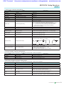
Software options: Waveform pattern
Waveform pattern options provide waveform data meeting the
requirements of various communication systems and can be used
by the MG3700A built-in arbitrary waveform generator.
Waveform patterns are downloaded to the MG3700A for use.
Model: MX370001A
Name: TD-SCDMA Waveform Pattern
Waveform patterns for transmission/reception test of 3GPP
1.28 Mcps TDD Option (TD-SCDMA)
Model: MX370002A
Name: Public Radio System Waveform Pattern
Waveform patterns complying with RCR STD-39 and ARIB
STD-T61/T79/T86.
Waveform patterns, such as Uplink/Downlink and
PN9/PN15 continuous waves.
RCR STD-39: N
arrow band digital-communications system
ARIB STD-T61: N
arrow band digital-communications
system
ARIB STD-T79: P
ublic digital-communications system
ARIB STD-T86: P
ublic digital-communications system
IQproducer
12
Product Brochure l
MG3700A
√
3GPP LTE (TDD)
√
3GPP LTE (FDD)
√
Fading
√
Multi-Carrier
ARIB STD-T61/T79/T86
√
TD-SCDMA
√
RCR STD-39
√
GPS
√
Bluetooth
√
ETC/DSRC
√
Digital Broadcast
(BS/CS/CATV/ISDB-T)
Digital Broadcast
(DVB-T/H)
WLAN
(IEEE802.11a/b/g)
Mobile WiMAX
(IEEE802.16e)
PDC
√
PHS
√
Advanced-PHS
GSM/EDGE
√
Next generation PHS
(XGP)
√
CDMA2000
√
CDMA2000 1xEV-DO
√
HSDPA/HSUPA
HSDPA
(Test Model 5)
Preinstalled
MX370001A
TD-SCDMA
MX370002A
Public Radio System
Standard accessories
AWGN
Standard accessories
W-CDMA
MX370101A
HSDPA/HSUPA
MX370102A
TDMA
MX370103A
CDMA2000 1xEV-DO
MX370104A
Multi-carrier
MX370105A
Mobile WiMAX
MX370106A
DVB-T/H
MX370107A
Fading
MX370108A
LTE FDD
MX370109A
XG-PHS
MX370110A
LTE TDD
W-CDMA
Waveform
pattern
Communication system
AWGN
Read the MX370x Series Software catalog for details.
√
√
√
√
√
√
√
√
√
√
Multi-carrier IQproducer is software that generates the multi-carrier signal based on waveform pattern of various
telecommunications systems.
√
√
Fading IQproducer is software that generates the Fading signal based on waveform pattern of various telecommunication
systems.
√
√
√
ООО "Техэнком"
Контрольно-измерительные приборы и оборудование
www.tehencom.com
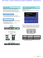
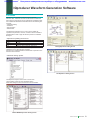
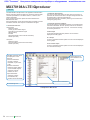
IQproducer Waveform Generation Software
Functions
IQproducer is PC application software used to generate
waveform files. These files are then transferred to the MG3700A
where they are used as the source of IQ data for modulated output.
It is bundled with MG3700A as standard and has the following four
functions:
• Parameter setting
• Simulation
• File generation
• Data transfer
The IQproducer software can run on any PC that meets the
operational requirements, however, a license must be installed on
the MG3700A in order to play the files and produce a modulated
RF signal.
• IQproducer Operating Environment
CPU
Memory
HDD
Display
OS
Pentium III, 1 GHz or faster
≥ 512 MB
≥ 5 GB
1024 × 768 pixels min.
Windows 2000 Professional, Windows XP
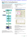
Fading IQproducer Setting Screen
Pentium® is registered trademarks of Intel Corporation or its
subsidiaries in the USA and other countries.
Windows® is a registered trademark of Microsoft Corporation in the
USA and other countries.
• Parameter setting: System
LTE IQproducer Setting Screen
The IQproducer System function has a GUI for each
communication system for easy parameter setting.
Parameter settings can also be saved to a file and recalled.
Mobile WiMAX IQproducer Setting Screen
Product Brochure l
MG3700A
13
ООО "Техэнком"
Контрольно-измерительные приборы и оборудование
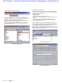
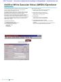
• Data transfer: Transfer and Setting
A PC and the MG3700A can be connected via 100BASE-TX
Ethernet to transfer data such as a waveform pattern generated by
IQproducer, firmware upgrade file, or graphics file.
Waveform patterns can be transferred to multiple MG3700A units
simultaneously when using a LAN connection.
After the files are moved to the MG3700A, the IQproducer can
remotely load the files into the waveform memory and select the
appropriate file for playback.
www.tehencom.com
Combination File generation
The Combination File Edit function is one of the Transfer & Setting
Edit functions. The following parameters are set automatically by
selecting the Combination File:
• Waveform pattern
• Repetition times
• Interference waveform pattern (Memory B)
•F
requency offset (Used when Memory A and Memory B are to be
added)
•L
evel ratio (This value represents C/N when Memory A and
Memory B are added, or the relative level between elements
when only Memory A is used)
Using Combination Files that place the wanted signal waveform
and the interference waveform into two separate memories makes
it easy to measure receiver characteristics. Combination files can
also be used to create sequences of waveforms.
By using Sequence Mode Combination files in which switching and
repetition times for multiple waveform patterns are defined, receive
signal status transitions can be verified.
Transfer & Setting Screen
Transfer & Setting Screen
Combination File Edit Screen
14
Product Brochure l
MG3700A
ООО "Техэнком"
Контрольно-измерительные приборы и оборудование
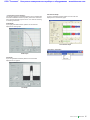
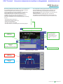
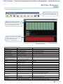
• Graphical Simulation Displays
This function displays a generated waveform as a Complementary
Cumulative Distribution Function (CCDF), Fast Fourier Transform
(FFT) and Time Domain graph on the PC. It is useful for checking
or reviewing waveforms.
www.tehencom.com
Time Domain Graph
Up to four generated waveform patterns can be read and
displayed as a Time Domain graph.
CCDF Graph
Up to eight generated waveform patterns can be read and
displayed as CCDF graphs.
Time Domain Graph
• Simulation: Simulation
CCDF Graph
FFT Graph
Up to four generated waveform patterns can be read and
displayed as FFT graphs.
FFT Graph
Product Brochure l
MG3700A
15
ООО "Техэнком"
Контрольно-измерительные приборы и оборудование
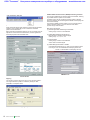
• File generation: File Gen
Convert: Data format conversion
ASCII-format IQ sample data created by general signal generation
software (such as MATLAB) can be converted to waveform
patterns for the MG3700A.
Data produced during R&D simulations can be converted using the
IQproducer and moved to the MG3700A to produce signals that
accurately reproduce the simulation data.
www.tehencom.com
Additive White Gaussian Noise (AWGN) waveform generation
This function establishes the sampling rate and bandwidth, allowing
any AWGN waveform pattern to be created.
In addition, when the first combined waveform pattern (Wanted
Signal) is selected, the Wanted Signal bandwidth and sampling rate
are set automatically.
The resulting AWGN waveform pattern can be combined with an
existing waveform pattern, which is useful for base-station
dynamic-range measurements.
Main setting parameters
(1) W
anted Signal BW: Wanted Signal bandwidth
Setting range: 0.0010 to 120.0000 MHz
(2) A
WGN BW (B)/Wanted Signal BW (A):
Magnification of AWGN to Wanted Signal
Setting range: 1.0, 1.5, 2.0, 2.5
(3) S
ampling Rate:
Setting range: 0.0200 to 160.0000 MHz
Same value as Wanted Signal.
(4) A
WGN BW (B): Bandwidth of AWGN
Calculated automatically from (1) and (2) under following items:
Limit range: 0
.001 to 20.000 MHz and Sampling rate/2 max.
20.001 to 120.000 MHz and Sampling rate max.
AWGN Screen
Convert Screen
Clipping
This function performs clipping of each type of waveform pattern.
The clipped waveform pattern is created by setting the filter,
bandwidth, and repletion times.
Clipping Graph
16
Product Brochure l
MG3700A
ООО "Техэнком"
Контрольно-измерительные приборы и оборудование
www.tehencom.com
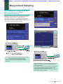
Measurement Sampling
Evaluating Receiver Characteristic for Base
Station and UEs of Various Mobile
Communications Systems
Because the MG3700A supports waveform patterns meeting the
requirements of mobile communications systems and includes a
built-in BER analyzer, it is ideal for measuring receiver
characteristics. The waveform combination function can combine
two waveform patterns, so a single MG3700A can output two
signals, such as the Wanted signal + Interference signal or Wanted
signal + AWGN (Additive White Gaussian Noise).
Wanted Signal + Interfering Screen
Output Waveform Screen
•T
he receiver sensitivity test covers BER measurement items
Examples: W-CDMA, GSM, PHS, and PDC
•S
ince the built-in BER analyzer is a standard feature, a
receiver test can be carried out easily without extra test
equipment.
• The receiver sensitivity test covers measurements using two
signals, such as Adjacent Channel Selectivity (ACS) and
blocking characteristic.
• The waveform combination function enables one MG3700A to
output a single RF signal containing the Wanted signal +
Interfering signal or the Wanted signal + AWGN.
• The level ratio accuracy is excellent because S/N adjustment
is performed by digital processing.
Product Brochure l
MG3700A
17
ООО "Техэнком"
Контрольно-измерительные приборы и оборудование
www.tehencom.com
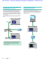
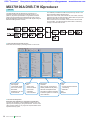
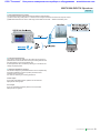
Evaluating Receiver Characteristics of
Multi-Mode Wireless Devices
Supports R&D of Evolving
Communication Systems
Multi-mode equipment that supports multiple wireless technologies
is now common. Signal generators that can support multiple
communication technologies are required for evaluating the
receiver characteristics of this equipment. Besides the traditional
receiver tests such as sensitivity and compression, additional
testing must be done to ensure that the receiver characteristics of
one technology are not degraded by the presence of a signal from
another technology.
The MG3700A supports all major telecommunication modulation
schemes. It can be used alone or as part of a system as shown
below.
The IQproducer data conversion function can be used to convert
customized waveform files created common EDA tools.
For example, an IQ sample data file simulated by MATLAB can be
converted to the waveform pattern file used by the MG3700A, so
the MATLAB simulation result can be compared with an actual
measurement result.
PC MATLAB
MG3700A Vector Signal Generator
DUT
•O
ne MG3700A can output the wanted signal for evaluating
receiver characteristic of various communication systems.
• It can also be used to generate interference signal for
evaluating degraded receiver characteristics caused by
mutual interference.
18
Product Brochure l
MG3700A
Signal Analyzer
ООО "Техэнком"
Контрольно-измерительные приборы и оборудование
www.tehencom.com
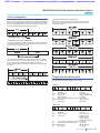
Specifications
• MG3700A Vector Signal Generator
The following conditions are applied unless otherwise specified. Common to CW mode and modulation mode. [Continuous mode: Off, External
ALC: Off, Frequency switching speed: Normal, Pulse modulation: Off], Only during modulation mode [Input level to DAC (RMS): Full scale 14 dB
to full scale 17 dB, Sampling rate: >100 kHz, Memory mode: Except combining two waveform, IQ Output: Off, After CAL execution, During
internal modulation]
Range
Resolution
Internal reference oscillator
External reference input
Buffer output (Reference output)
Frequency
Switching time
Frequency setup and Display
Settable range
Unit
Resolution
250 kHz to 3 GHz (Standard), 250 kHz to 6 GHz (Option)
0.01 Hz
Frequency: 10 MHz, Aging rate: ±1 × 10⁻⁸/day, ±1 × 10⁻⁷/year, Temperature stability: ±2 × 10⁻⁸ (0˚ to 50°C),
Start-up characteristics (at 23°C):
±5 × 10⁻⁸ (After 5 min, compared to frequency after 24 h warm-up)
With Rubidium Reference Oscillator Option
Frequency: 10 MHz, Aging rate: ±1 × 10⁻¹⁰/Month, Temperature stability: ±1 × 10⁻⁹ (0˚ to 50°C),
Start-up characteristics (at 23°C):
±1 × 10⁻⁹ (After 7 min, compared to frequency after 24 h warm-up)
Frequency: 5 MHz/10 MHz (auto-switching), Operating range: ±1 ppm,
Input level:≥0.7 Vp-p/50 Ω (AC coupled), Connector: BNC-J (rear panel, Ref Input)
Frequency: 10 MHz, Output level: TTL (DC-coupled), Connector: BNC-J (rear panel, Buffered Output)
Response time from final command to ±0.1∗ ppm of set frequency on GPIB
∗: (When set frequency is 1 GHz or less, response time from final command to ±100 Hz)
When Frequency change speed = Normal:
≤40 ms (When exceeding 3 GHz)
≤15 ms (When the amount of frequency change is less than 1 GHz without exceeding 3 GHz)
≤20 ms (When the amount of frequency change is 1 GHz or more without exceeding 3 GHz)
When Frequency change speed = Fast:
≤40 ms (When exceeding 3 GHz)
≤10 ms (When not exceeding 3 GHz)
With Mechanical Attenuator Option
Regardless of frequency change speed.:
≤100 ms (When exceeding 3 GHz)
≤80 ms (When not exceeding 3 GHz)
Direct setup: Absolute value of frequency is set up and displayed.
Setup by CH: CH assigned to frequency. Separate CH tables can be assigned to two or more systems
(groups). Group names and CH numbers are set and displayed. Furthermore, the
corresponding frequency is displayed simultaneously.
–140 to +13 dBm (At CW, accuracy range: –136 to +6 dBm)
With Mechanical Attenuator Option
–140 to +19 dBm (At CW, accuracy range: –136 to +10 dBm)
∗: Refer to Vector modulation. At vector modulation, level error in compared with CW for level accuracy
at vector modulation.
Power: dBm
Voltage: dBµV (terminate voltage display), dBµV (open voltage display)
0.01 dB (dBm, dBµV)
At CW and 23 ±5°C:
Level (p) [dBm]
+3 < p ≤ +6
–1 < p ≤ +3
–120 ≤ p ≤ –1
–127 ≤ p < –120
–136 ≤ p < –127
Accuracy
Output level
3 G < f ≤ 6 G∗
―
±0.8 dB
±0.8 dB
±2.5 dB typ.
―
With Mechanical Attenuator Option
+7 < p ≤ +10
–100 ≤ p ≤ +7
–120 ≤ p < –100
–127 ≤ p < –120
–136 ≤ p < –127
Switching time
Frequency (f) [Hz]
25 M ≤ f ≤ 3 G
±0.5 dB
±0.5 dB
±0.5 dB
±0.7 dB
±1.5 dB typ.
∗: Upper frequency 6 GHz option required for 3 GHz < f ≤ 6 GHz.
Level (p) [dBm]
Linearity
250 k ≤ f < 25 M
―
―
±0.5 dB typ.
―
―
250 k ≤ f < 25 M
±0.5 dB typ.
±0.5 dB typ.
±0.5 dB typ.
―
―
Frequency (f) [Hz]
25 M ≤ f ≤ 3 G
±0.5 dB
±0.5 dB
±0.5 dB
±0.7 dB
±1.5 dB typ.
3 G < f ≤ 6 G∗
―
±0.8 dB
±1.0 dB
±2.5 dB typ.
―
∗: Upper frequency 6 GHz options required for 3 GHz < f ≤ 6 GHz.
At CW, –11 dBm and at 23 ±5°C:
±0.2 dB typ. (at –120 to –11 dBm, 25 MHz ≤ f ≤ 3 GHz)
±0.3 dB typ. (at –120 to –11 dBm, 3 GHz < f ≤ 6 GHz)
With Mechanical Attenuator Option
At CW, –7 dBm and at 23 ±5°C:
±0.2 dB typ. (at –120 to –7 dBm, 25 MHz ≤ f ≤ 3 GHz)
±0.3 dB typ. (at –120 to –7 dBm, 3 GHz < f ≤ 6 GHz)
Response time from final command to ±0.1 dB of final level on GPIB.
f < 25 MHz: ≤15 ms (Normal mode), ≤10 ms (Continuous mode)
f ≥ 25 MHz: ≤10 ms (Not based on mode)
With Mechanical Attenuator Option
≤80 ms (Normal mode), ≤10 ms (Continuous mode)
Product Brochure l
MG3700A
19
ООО "Техэнком"
Контрольно-измерительные приборы и оборудование
VSWR
Special setting mode
Continuous mode
Output level
EXT ALC mode
Output connector
Maximum reverse input
Spurious
Harmonics
Signal purity
Non harmonic
Power supply relation
EVM
ACLR (5 MHz offset)
ACLR (10 MHz offset)
Vector modulation
At vector modulation,
level error in comparison
with CW
(At modulation mode, ALC: Off)
Carrier leakage
Image rejection
External modulation
RF Spectrum invert
Internal modulation
Pulse modulation
External modulation
Output voltage range
Output voltage amplitude
IQ Output
DC Offset variable range
Output connector
Arbitrary function
generation
20
Product Brochure l
Waveform resolution
LPF
MG3700A
www.tehencom.com
At ≤–11 dBm output level: 1.3 (250 kHz ≤ f ≤ 3 GHz), 1.55 (3 GHz < f ≤ 6 GHz)
With Mechanical Attenuator Option
At ≤–7 dBm output level: 1.25 (250 kHz ≤ f ≤ 3 GHz), 1.35 (3 GHz < f ≤ 6 GHz)
Continuous mode and EXT ALC mode are exclusive modes
By switching to the Continuous mode, the reference output level can be adjusted continuously in 0.01
dB steps over the range of +3 to –10 dB.
Output level is changed according to DC voltage input externally
Variable range: –8/+3 dB, Input impedance: 600 Ω (nominal),
Connector: BNC-J (rear panel, Ext. ALC)
50 Ω, N-J (front panel, RF Output)
Reverse input power: 1 Wpeak (≥300 MHz), 0.25 Wpeak (<300 MHz), DC: 0 V
With Mechanical Attenuator Option
Reverse input power: 1 Wpeak, DC: 0 V
At CW, ≤–1 dBm (With Mechanical Attenuator Option: ≤+3 dBm)
<–30 dBc (f ≥300 MHz @E-ATT, f ≥250 kHz @M-ATT)
<–60 dBc (Expect the intersection spurious∗ of 2.4 GHz, 25 MHz to 3 GHz)
<–54 dBc (Expect the intersection spurious∗ of 4.4 GHz, 3 to 6 GHz)
∗: Intersection spurious: 4.8 GHz – [output frequency] (at 25 MHz to 3 GHz),
8.8 GHz – [output frequency] (at 3 to 6 GHz)
<–50 dBc (250 kHz to 3 GHz), <–44 dBc (3 to 6 GHz)
At 23 ±5°C and Output level ≤–1 dBm (With Mechanical Attenuator Option: ≤+3 dBm)
≤2% rms., ≤1% rms typ. (at W-CDMA Downlink 1 code modulation,
Output frequency: 800 to 1000 MHz, 1800 to 2400 MHz)
At 23 ±5°C and Output level ≤–4 dBm (With Mechanical Attenuator Option: ≤0 dBm)
≤1% rms. (at OFDM modulation equal to IEEE802.11a/g,
Output frequency: 2400 to 2497 MHz, 4,900 to 5,925 MHz)
≤5% peak (at modulation equal to IEEE802.11b, Output frequency: 2,400 to 2,497 MHz)
At 23 ±5°C when using signal of W-CDMA (Test Model1 64DPCH):
–61 dBc/3.84 MHz, –63 dBc/3.84 MHz typ. (≤–4 dBm, 800 to 1000 MHz, 1800 to 2400 MHz)
With Mechanical Attenuator Option
–62 dBc/3.84 MHz, –64 dBc/3.84 MHz typ. (≤0 dBm, 800 to 1000 MHz, 1800 to 2400 MHz)
At 23 ±5°C when using signal of W-CDMA (Test Model1 64DPCH):
–66 dBc/3.84 MHz typ. (≤–1 dBm, 800 to 1000 MHz, 1800 to 2400 MHz)
With Mechanical Attenuator Option
–67 dBc/3.84 MHz typ. (≤+3 dBm, 800 to 1000 MHz, 1800 to 2400 MHz)
±0.2 dB [when outputting W-CDMA Downlink 1 code, 1 carrier]
At guaranteed range (Level) of level accuracy under following modulation conditions
50 MHz ≤ f ≤ 3 GHz: Level ≤+2 dBm
3 GHz < f ≤ 6 GHz: Level ≤–1 dBm
With Mechanical Attenuator Option
50 MHz ≤ f ≤ 3 GHz: Level ≤+7 dBm
3 GHz < f ≤ 6 GHz: Level ≤+4 dBm
≤–40 dBc (at 23 ±5°C)
≤–40 dBc (at 23 ±5°C. When using complex sine wave of 10 MHz or less)
Input level: √(I2 + Q2) = 0.5 V (rms.), Maximum input level: –5 V (peak) ≤I, Q ≤+5 V (peak),
Input impedance: 50 Ω, Input connector: BNC-J (Front panel, Modulation Input IQ)
I, Q signal changeable when internal modulation.
Spectrum Normal: Usual spectrum output
Spectrum Reverse: Inverted spectrum output
ON/OFF ratio: >60 dB, Rise/fall time: <90 ns (10 to 90%), Pulse repetition frequency: DC to 1 MHz,
(Duty 50%)
Input range: 0 to 5 V, Input level threshold: about 1 V, ON/OFF ratio: >60 dB, Rise/Fall time: <90 ns
(10 to 90%), Pulse repetition frequency: DC to 1 MHz, (Duty 50%), Input connector: 50 Ω
BNC-J (rear panel, Ext Pulse Mod Input)
When output open. Output voltage amplitude + DC offset: –3.5 to +3.5 V
When output open.
Amplitude change:
• I and I changes simultaneously
• Q and Q changes simultaneously
• I/I and Q/Q changes independently
Amplitude variable range: 0 to 120% (100% = 640 mV rms, rms = 1634)
Variable step: 0.1%
Accuracy: ±0.5 dB (1 kHz sine wave, Amplitude variable range ≥10%)
In-phase DC offset: Variable range: –1 to +3 V, Resolution: 10 mV
Differential DC offset: Variable range: –50 to +50 mV, Resolution: 50 µV
50 Ω, D-Sub 15-J (rear panel, IQ Output, differential), Pin assignment (10 = I, 11 = I, 13 = Q, 14 = Q,
other = GND)
14 bit
Automatic selection and manual selection
100, 300 kHz, 1, 3, 10, 30, 70 MHz, Through
ООО "Техэнком"
Контрольно-измерительные приборы и оборудование
Function
Marker output
Baseband
reference
clock signal
Number of ports
Connector
Internal clock signal
External clock input signal
Memory capacity
Number of opened files
Waveform memory
Memory mode
Function
Start/Frame trigger
Input connector
Start trigger
Frame trigger
Function
Pattern trigger
BER
Measurement
function
(Standard)
Input connector
Function
Input connector
Input signal
Input level
Input threshold level
Input bit rate
Measurable patterns
Measurable BER
Measurable time
Mode
Display
Measurable bit count
Auto Resync function
www.tehencom.com
When a signal is allotted to a marker signal bit at waveform generation, up to three signals, such as
pulse modulation signal (for internal modulation), frame timing signal, etc., can be output.
The polarity can also be reversed.
3 ports
TTL, BNC-J (rear panel, AUX Input/Output Connector 1/2/3)
Range: 20 kHz to 160 MHz, Resolution: 0.001 Hz
Input frequency range: 20 kHz to 40 MHz
Divide and multiply functions: Signal of 1, 2, 4, 8, 16, 1/2, 1/4, 1/8, 1/16 times of input frequency
generated internally, and used as DAC sampling clock
Connector: BNC-J (rear panel, Baseband Reference Clock)
Input level:≥0.7 V (p-p)/50 Ω (AC coupled)
Waveform memories. A and B.
128 Msamples/channel × 2, 256 Msamples/channel Max.
With ARB Memory Upgrade 512 Msample option
256 Msamples/channel × 2, 512 Msamples/channel Max.
Up to 4096 waveform patterns opened per waveform memory (A/B)
100 packages per waveform memory, 100 patterns in one package.
Minimum number of samples per pattern: 100
Defined Mode
Selection of a single waveform pattern to be used in either waveform memory A or B, selection of
waveform patterns using a combination file that defines addition of multiple waveform patterns, and
the addition level ratio can be set in this mode.
If a combination file that specifies two or more waveform patterns in waveform memory A is selected,
the following sequence operations become enabled.
• Selection of pattern switching mode (Auto/Manual)
• Selection of pattern switching point (Frame end/Pattern end)
• Switching of pattern by an external trigger signal
(enabled when the pattern switching mode is Manual)
• Restart of sequence
• Maximum number of elements: 200
• Minimum number of points per pattern: 1000
Level ratio setting range: Two-signal level ratio <80 dB or OFF
Level setting resolution: 0.01 dB
Frequency offset variable width: ± (0.8 × Sampling Clock × 2n – Bandwidth)/2
(n: Maximum integer that satisfying Sampling Clock × 2n ≤80 MHz when sampling clock greater than
20 MHz.)
Frequency setting resolution: 1 Hz
In this mode, two waveform memories can be connected for use as a 256 Msamples long memory
(512 Msamples long when ARB Memory Upgrade 512 Msample option installed).
Edit Mode
One waveform each is selected from waveform memory A and waveform memory B, these two
waveforms are added and then output.
Two signal levels, the waveform memory B start offset and frequency offset, can be set.
Level ratio setting range: Two-signal level ratio <80 dB or OFF
Level setting resolution: 0.01 dB
Frequency offset variable width: ± (0.8 × Sampling Clock × 2n – Bandwidth)/2
(n: Maximum integer that satisfying Sampling Clock × 2n ≤80 MHz when sampling clock greater than
20 MHz.)
Frequency setting resolution: 1 Hz
Switchable between continuous output and burst output.
Functional change: Connector shared by Start trigger and Frame trigger; switched depending on
situation
Connector: BNC-J (Front panel, Start/Frame Trigger), Input level: TTL,
Logic: Polarity Rise/Fall selected.
Starts waveform output
Searches for burst timing at burst output
Burst length data output and timing of frame trigger and waits for next frame trigger
When using the sequence mode, the pattern trigger will force a pattern switch.
Connector: Front panel, Pattern Trigger, BNC-J connector
Input level: TTL
Logic: Rising or falling polarity
BER Measurement of demodulated data sequence
TTL, BNC-J (rear panel, BER Input)
Data, Clock, Enable (Polarity reversal supported.)
TTL
Matches threshold (0.8 to 2.4 V) of TTL
1 kbps to 20 Mbps
PN 9, 11, 15, 20, 23, ALL0, ALL1, ALT (alternating 0 and 1)
0 to 1% (Reference value; changes with system conditions and data rate)
≤359999.0 sec
Single, Endless, Continuous.
BitError, SyncLoss, ClockError, EnableError, Error Rate, Error Count
1000 to 4294967295 (232 – 1) bit
Switched between enable/disable
Product Brochure l
MG3700A
21
ООО "Техэнком"
Контрольно-измерительные приборы и оборудование
Function
Connector
Input signal
Input level
Input threshold level
Input impedance
Adjustable range of input
timing
Input bit rate
BER Measurement
function
(Option:
MG3700A-031,
MG3700A-131)
Measurable patterns
Measurable BER
Measurable bit count
Measurable error bit
Auto Resync
Measurement mode
Display
GPIB
External interface
100BASE-TX Ethernet
Memory card
Display
Power supply
Temperature range
Dimensions and
mass
Size
On/Off setting
Screen save
Voltage
Frequency
Power consumption
Operating temperature
Storage temperature
Dimensions
Mass
EMC
LVD
22
Product Brochure l
MG3700A
www.tehencom.com
BER Measurement of demodulated data
Rear panel, BER Input, BNC-J connector
Data, Clock, Enable (Polarity reversal supported)
0 to 5 V
0.20 to 3.00 V (0.05 V step)
50 Ω, High impedance
–1 to +15 clock (Data/Enable adjusted for input Clock)
100 bps to 120 Mbps
PN 9, 11, 15, 20, 23, ALL0, ALL1, ALT (alternating 0 and 1)
PN 9fix, 11fix, 15fix, 20fix, 23fix, UserDefine
0 to 10% (Reference value; changes with system conditions and data rate)
1000 to 4294967295 (232 – 1) bit
1 to 2147483647 (231 – 1) bit
ON/OFF:
Select ON when SyncLoss and Threshold error detecting is used to control the measurement cycle.
Measurement will stop when the SyncLoss or Threshold error criteria is satisfied.
Select OFF when SyncLoss and Threshold error detecting is not to be performed.
Threshold setting range:
[numerator/denominator] Choose from denominator = 500, 5000, 50000,
numerator = 1 to denominator/2, (Default: 200/500)
Single, Continuous, Endless
BitError, SyncLoss, ClockError, Enable Error, SyncLoss Count, Overflow Data Count, Overflow
SyncLoss, Error Rate, Error Count
Control target: All functions except MAIN PWR switch, [Local] key, and screen contrast keys.
Interface: SH1, AH1, T6, L4, TE0, SR1, RL1, PP0, DC1, DT1, C0, E2
Connector: GPIB (rear panel, GPIB)
Function: Waveform pattern transfer and control.
Connector: RJ45 jack (front panel and rear panel, Ethernet)
In order to use the Ethernet jack on the front panel, it is necessary to jumper the two Ethernet jacks on
the rear panel using the straight-through cable (standard accessory).
Function: Waveform pattern, memory parameters, software, and CH table can be saved or recalled to/
from CompactFlash card
Connector: Slot (front panel, CF Card)
8.4-inch, 640 × 480 dots, color TFT LCD
Panel display On/Off
Currently displayed screen saved to HDD/CF card as bitmap file
100 to 120 V, 200 to 240 Vac (–15/+10%, 250 V Max.)
47.5 to 63 Hz
≤200 VA
+5˚ to +45°C
–20˚ to +60°C
426 (W) × 177 (H) × 451 (D) mm
≤15 kg (excluding option)
EN61326-1, EN61000-3-2
EN61010-1
ООО "Техэнком"
Контрольно-измерительные приборы и оборудование
www.tehencom.com
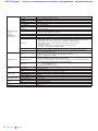
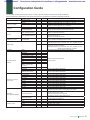
Configuration Guide
The MG3700A Vector Signal Generator supports a variety of general hardware and software as standard equipment.
Use the chart below to select options when higher performance than provided by the standard configuration is desired.
Classification
Frequency range
Reference oscillator
Outline
250 kHz to 3 GHz
250 kHz to 6 GHz
Standard
Option
√
√
Rubidium Reference Oscillator
Electron Attenuator
Attenuator
Standard
√
√
√
√
Memory
2 GB = 512 Msamples/channel
Baseband generator
Internal/External
√
√
√
BER Analyzer
√
Hard disk
Waveform patterns
software∗
IQproducer License for
each system∗
IQproducer
(PC application software)∗
Warranty service
6 GHz Frequency Extension Option
Frequency: 10 MHz, Aging rate: ±1 × 10⁻⁸/day, ±1 × 10⁻⁷/year
Rubidium Reference Oscillator Option
Frequency: 10 MHz, Aging rate: ±1 × 10⁻¹⁰/Month
√
Mechanical Attenuator
1 GB = 256 Msamples/channel
Note
40 GB
W-CDMA
GSM/EDGE
CDMA2000 1X/1xEV-DO
W-LAN (IEEE802.11a/b/g)
PDC
PHS
Bluetooth
GPS
Digital Broadcast
(ISDB-T 1 segment, BS,
CS, CATV)
AWGN
TD-SCDMA
Public Radio System
(ARIB STD-T61/T79/T86)
HSDPA/HSUPA
Universal TDMA
CDMA2000 1xEV-DO
Multi-carrier
Mobile WiMAX
DVB-T/H
Fading
LTE FDD
Next generation PHS (XGP)
LTE TDD
√
√
√
√
√
√
√
√
√
Parameter setting function
√
Data converter function
√
Data transfer function
√
Simulator function
1 year
2 years
3 years
5 years
√
√
Mechanical Attenuator Option
Changes electronic attenuator to mechanical attenuator
128 Msamples/channel × 2
Maximum of 256 Msamples/channel
ARB Memory Upgrade 512 Msample Option
256 Msamples/channel × 2
Maximum of 512 Msamples/channel
Vector modulation bandwidth (Internal): 120 MHz
Vector modulation bandwidth (External): 150 MHz
Input bit rate: 1 kbps to 20 Mbps
Measurable Patterns: PN 9/11/15/20/23, ALL0, ALL1, repetition of 0 and 1
High speed BER Test function
Input bit rate: 100 bps to 120 Mbps
Measurable Patterns: PN 9/11/15/20/23, ALL0, ALL1, repetition of 0 and 1
PN9fix/11fix/15fix/20fix/23fix, UserDefine
Hard disk for saving waveform patterns and parameters
Waveform patterns saved hard disk
License required
√
√
√
License required (Model: MX370001A)
√
License required (Model: MX370002A)
√
√
√
√
√
√
√
√
√
√
License required (Model: MX370101A)
License required (Model: MX370102A)
License required (Model: MX370103A)
License required (Model: MX370104A)
License required (Model: MX370105A)
License required (Model: MX370106A)
License required (Model: MX370107A)
License required (Model: MX370108A)
License required (Model: MX370109A)
License required (Model: MX370110A)
Various parameters of waveform pattern edited easily
Parameter edit results saved as a setting file and can recalled
Setting files converted to MG3700A waveform pattern
License required for each system
Setting file programmed in C or MATLAB
converted to a waveform pattern without license
Waveform patterns, display copy files, and update programs transferred
from PC to MG3700A via Ethernet
For checking waveform pattern before transferring to MG3700A
√
√
√
Standard 1 year + 1 year
Standard 1 year + 2 years
Standard 1 year + 4 years
∗: Read the waveform pattern and IQproducer data sheet for details.
Product Brochure l
MG3700A
23
ООО "Техэнком"
Контрольно-измерительные приборы и оборудование
www.tehencom.com
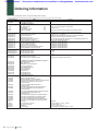
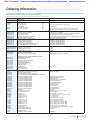
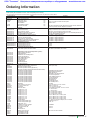
Ordering Information
Please specify model/order number, name, and quantity when ordering.
The names listed in the chart below are Order Names. The actual name of the item may differ from the Order Name.
Model/Order No.
MG3700A
J0017F
J1276
J1254
Z0742
MG3700A-ES210
MG3700A-ES310
MG3700A-ES510
― Options ―
Rubidium Reference Oscillator
Mechanical Attenuator
Upper Frequency 6 GHz
ARB Memory Upgrade 512 Msample
High Speed BER Test Function
Rubidium Reference Oscillator Retrofit
Mechanical Attenuator Retrofit
Electronic Attenuator Retrofit
Upper Frequency 6 GHz Retrofit
ARB Memory Upgrade 512 Msample Retrofit
High Speed BER Test Function Retrofit
― Maintenance service ―
Extended Warranty Service
Extended Warranty Service
Extended Warranty Service
MX370001A
MX370002A
― Softwares (Waveform pattern) ―
TD-SCDMA Waveform Pattern
Public Radio System Waveform Pattern
MG3700A-001
MG3700A-002
MG3700A-011
MG3700A-021
MG3700A-031
MG3700A-101
MG3700A-102
MG3700A-103
MG3700A-111
MG3700A-121
MG3700A-131
MX370101A
MX370102A
MX370103A
MX370104A
MX370105A
MX370106A
MX370107A
MX370108A
MX370109A
MX370110A
Z0777
W2495AE
W2496AE
W2539AE
W2533AE
W2503AE
W2504AE
W2505AE
W2633AE
W2734AE
W2798AE
W2995AE
W3022AE
W3152AE
W3221AE
G0141
K240B
MA1612A
MP752A
MA2512A
24
Name
― Main frame ―
Vector Signal Generator
― Standard accessories ―
Power Cord, 2.6 m: LAN Straight Cable: CompactFlash:
CompactFlash Adapter: MG3700A CD-ROM: Product Brochure l
Remarks
1 pc
1 pc
1 pc
1 pc
1 pc
― Softwares (License key for IQproducer system) ―
HSDPA/HSUPA IQproducer
TDMA IQproducer
CDMA2000 1xEV-DO IQproducer
Multi-carrier IQproducer
Mobile WiMAX IQproducer
DVB-T/H IQproducer
Fading IQproducer
LTE IQproducer
XG-PHS IQproducer
LTE TDD IQproducer
― Optional accessories ―
Standard Waveform Pattern Upgrade Kit
MG3700A Operation Manual
MG3700A IQproducer Operation Manual
MG3700A Standard Waveform Pattern Operation Manual
MX370001A TD-SCDMA Waveform Pattern
Operation Manual
MX370101A HSDPA/HSUPA IQproducer
Operation Manual
MX370102A TDMA IQproducer Operation Manual
MX370103A CDMA2000 1xEV-DO IQproducer
Operation Manual
MX370104A Multi-carrier IQproducer Operation Manual
MX370105A Mobile WiMAX IQproducer
Operation Manual
MX370106A DVB-T/H IQproducer Operation Manual
MX370107A Fading IQproducer Operation Manual
MX370108A LTE IQproducer Operation Manual
MX370109A XG-PHS IQproducer Operation Manual
MX370110A LTE TDD IQproducer Operation Manual
HDD ASSY
Power Divider (K connector)
Four-port Junction Pad
Termination
Band Pass Filter
MG3700A
10 cm, For U link connection on Rear panel
64 MB or more
Main frame operation manual, IQproducer operation manual,
Standard waveform operation manual, IQproducer software
Aging rate: ±1 × 10⁻¹⁰/Month
Changes standard electronic attenuator to mechanical attenuator
250 kHz to 3 GHz extended to 250 kHz to 6 GHz
Extends standard 128 Msample/channel × 2 to 256 Msample/channel × 2
Extends standard BER test function
Retrofitted to shipped MG3700A
Retrofitted to shipped MG3700A
Retrofitted to shipped MG3700A
Retrofitted to shipped MG3700A
Retrofitted to shipped MG3700A
Retrofitted to shipped MG3700A
2 years
3 years
5 years
RCR STD-39, ARIB STD-T61/T79/T86
DVD 4 piece sets
Hard disk
DC to 26.5 GHz, K-J, 50 Ω, 1 Wmax
5 MHz to 3 GHz, N-J
DC to 12.4 GHz, 50 Ω, N-P
For W-CDMA, pass band: 1.92 to 2.17 GHz
ООО "Техэнком"
Model/Order No.
J0576B
J0576D
J0127A
J0127B
J0127C
J0322A
J0322B
J0322C
J0322D
J0004
J1261B
J1261D
J0008
J1277
B0329C
B0331C
B0332
B0333C
B0334C
P0021
P0022
P0023
Контрольно-измерительные приборы и оборудование
Name
Coaxial Cord, 1.0 m
Coaxial Cord, 2.0 m
Coaxial Cord, 1.0 m
Coaxial Cord, 2.0 m
Coaxial Cord, 0.5 m
Coaxial Cord, 0.5 m
Coaxial Cord, 1.0 m
Coaxial Cord, 1.5 m
Coaxial Cord, 2.0 m
Coaxial Adapter
Ethernet Cable (Shield Type)
Ethernet Cable (Shield Type)
GPIB Cable, 2.0 m
IQ Output Conversion Adapter
Front Cover for 1MW 4U
Front Panel Handle Kit
Joint Plate
Rack Mount Kit
Hardtype Carrying Case
CompactFlash 128 MB
CompactFlash 256 MB
CompactFlash 512 MB
www.tehencom.com
Remarks
N-P · 5D-2W · N-P
N-P · 5D-2W · N-P
BNC-P · RG-58A/U · BNC-P
BNC-P · RG-58A/U · BNC-P
BNC-P · RG-58A/U · BNC-P
SMA-P · SMA-P, DC to 18 GHz, 50 Ω
SMA-P · SMA-P, DC to 18 GHz, 50 Ω
SMA-P · SMA-P, DC to 18 GHz, 50 Ω
SMA-P · SMA-P, DC to 18 GHz, 50 Ω
N-P · SMA-J Conversion Adapter, DC to 12.4 GHz
Straight-through, 3 m
Cross, 3 m
D-Sub/BNC
2 pcs/set
4 pcs/set
With front cover and a casters
Typical (typ):
Performance not warranted. Must products meet typical performance.
Nominal:
Values not warranted. Included to facilitate application of product.
Example:
Performance not warranted. Data actually measured by randomly selected measuring instruments.
Trademarks:
• IQproducer™ is a registered trademark of Anritsu Corporation.
• MATLAB® is a registered trademark of The MathWorks, Inc.
• CDMA2000® is a registered trademark of the Telecommunications Industry Association (TIA-USA).
• The Bluetooth ® mark and logos are owned by Bluetooth SIG, Inc. and are used by Anritsu under license.
• Pentium® is registered trademarks of Intel Corporation or its subsidiaries in the USA and other countries.
• Windows® is a registered trademark of Microsoft Corporation in the USA and other countries.
• CompactFlash® is a registered trademark of SanDisk Corporation in the United States and is licensed to CFA (Compact Flash Association).
• WiMAX® is a trademark or registered trademark of WiMAX Forum.
• Other companies, product names and service names are registered trademarks of their respective companies.
Product Brochure l
MG3700A
25
ООО "Техэнком"
Контрольно-измерительные приборы и оборудование
Note:
26
Product Brochure l
MG3700A
www.tehencom.com
ООО "Техэнком"
Контрольно-измерительные приборы и оборудование
www.tehencom.com
Note:
Product Brochure l
MG3700A
27
ООО "Техэнком"
Контрольно-измерительные приборы и оборудование
www.tehencom.com
6SHFLILFDWLRQVDUHVXEMHFWWRFKDQJHZLWKRXWQRWLFH
$QULWVX&RUSRUDWLRQ
2QQD$WVXJLVKL.DQDJDZD-DSDQ
3KRQH
)D[
%86$
$QULWVX&RPSDQ\
(DVW&ROOLQV%OYG6XLWH5LFKDUGVRQ
7;86$
7ROO)UHH
3KRQH )D[
%&DQDGD
$QULWVX(OHFWURQLFV/WG
6LOYHU6HYHQ5RDG6XLWH.DQDWD
2QWDULR.9&&DQDGD
3KRQH
)D[
%%UD]LO
$QULWVX(OHWU{QLFD/WGD
3UDFD$PDGHX$PDUDO$QGDU
3DUDLVR6mR3DXOR%UD]LO
3KRQH
)D[
%0H[LFR
$QULWVX&RPSDQ\6$GH&9
$Y(MpUFLWR1DFLRQDO1R3LVR&RO*UDQDGD
0p[LFR')0p[LFR
3KRQH
)D[
%8.
$QULWVX(0($/WG
&DSDELOLW\*UHHQ/XWRQ%HGIRUGVKLUH/8/88.
3KRQH
)D[
%)UDQFH
%,WDO\
%6LQJDSRUH
9LD(OLR9LWWRULQL5RPD,WDO\
3KRQH
)D[
$OH[DQGUD7HUUDFH7KH&RPWHFK/REE\$
6LQJDSRUH
3KRQH
)D[
$QULWVX6S$
%6ZHGHQ
$QULWVX$%
%RUJDIMRUGVJDWDQ.,67$6ZHGHQ
3KRQH
)D[
%)LQODQG
$QULWVX$%
7HNQREXOHYDUGL),9$17$$)LQODQG
3KRQH
)D[
%'HQPDUN
$QULWVX$6
.LUNHEMHUJ$OOp'.%U¡QGE\'HQPDUN
3KRQH
)D[
%6SDLQ
$QULWVX(0($/WG
2ILFLQDGH5HSUHVHQWDFLyQHQ(VSDxD
(GLILFLR9HJDQRYD
$YGDGHOD9HJDQÝHGISORI
$/&2%(1'$60DGULG6SDLQ
3KRQH
)D[
%5XVVLD
$QULWVX(0($/WG
5HSUHVHQWDWLRQ2IILFHLQ5XVVLD
7YHUVND\DVWUEOGWKIORRU
5XVVLD0RVFRZ
3KRQH
)D[
%*HUPDQ\
32%R['XEDL,QWHUQHW&LW\
$O7KXUD\D%XLOGLQJ7RZHU6XLWWK)ORRU
'XEDL8QLWHG$UDE(PLUDWHV
3KRQH
)D[
1HPHWVFKHN+DXV.RQUDG=XVH3ODW]
0QFKHQ*HUPDQ\
3KRQH
)D[
UG)ORRU6KUL/DNVKPLQDUD\DQ1LZDVIW5RDG
+$/UG6WDJH%DQJDORUH,QGLD
3KRQH
)D[
%35&KLQD+RQJ.RQJ
$QULWVX&RPSDQ\/WG
8QLWVWK)ORRU*UHHQILHOG7RZHU&RQFRUGLD3OD]D
1R6FLHQFH0XVHXP5RDG7VLP6KD7VXL(DVW
.RZORRQ+RQJ.RQJ
3KRQH
)D[
%35&KLQD%HLMLQJ
$QULWVX&RPSDQ\/WG
%HLMLQJ5HSUHVHQWDWLYH2IILFH
5RRP%HLMLQJ)RUWXQH%XLOGLQJ
1R'RQJ6DQ+XDQ%HL5RDG
&KDR<DQJ'LVWULFW%HLMLQJ35&KLQD
3KRQH
)D[
%.RUHD
$QULWVX&RUSRUDWLRQ/WG
)+\XQMXN%XLOGLQJ<HRNVDP'RQJ
.DQJQDPNX6HRXO.RUHD
3KRQH
)D[
$QULWVX3W\/WG
$QULWVX6$
$QULWVX*PE+
%,QGLD
$QULWVX3WH/WG
,QGLD%UDQFK2IILFH
%$XVWUDOLD
%8QLWHG$UDE(PLUDWHV
DYHQXHGX4XpEHF6,/,&
&2857$%2(8)&('(;)UDQFH
3KRQH
)D[
$QULWVX3WH/WG
$QULWVX(0($/WG
'XEDL/LDLVRQ2IILFH
8QLW)HUQWUHH*XOO\5RDG1RWWLQJ+LOO
9LFWRULD$XVWUDOLD
3KRQH
)D[
%7DLZDQ
$QULWVX&RPSDQ\,QF
)1R6HF1HLKX5G7DLSHL7DLZDQ
3KRQH
)D[
3OHDVH&RQWDFW
3ULQWHGRQ5HF\FOHG3DSHU
Catalog No. MG3700A-E-A-1-(11.00)
Printed in Japan
19/JUN/2009 ddc/CDT
ООО "Техэнком"
Контрольно-измерительные приборы и оборудование
www.tehencom.com
Product Brochure
MG3700A Vector Signal Generator
MX370x series software
MX3700xxA Waveform Pattern
ООО "Техэнком"
Контрольно-измерительные приборы и оборудование
www.tehencom.com
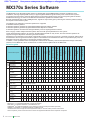
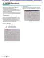
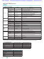
MX370x Series Software
The MG3700A Vector Signal Generator features a 160-MHz high-speed ARB baseband generator, broadband vector
modulation, and large-capacity ARB memory to support digital modulation signals used by most communication systems.
Its excellent cost performance offers the ideal solution for generating signals used by the new and growing field of wireless
broadband technology, as well as for mobile telecommunications systems and wireless LANs.
Because the MG3700 has a built-in ARB generator, signals are output easily just by selecting the waveform pattern matching
the required communication system.
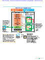
The following four categories of waveform patterns are supported:
● Standard waveform patterns
● Waveform patterns generated by optional MX3700xxA Waveform Pattern software
● Waveform patterns generated by optional MX3701xxA IQproducer software
● Waveform patterns converted from data generated by common signal-generation software
Each category contains multiple waveform pattern files each with preset parameters for each system.
These default waveform patterns are saved on the MG3700A hard disk for easy access, but other waveform patterns are
supported using the IQproducer waveform generation software.
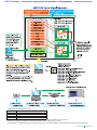
Parameters for the waveform for the target communication system are set using a GUI to a generate a waveform pattern file for
the MG3700A. After the generated waveform pattern is downloaded to the MG3700A via LAN or CompactFlash (CF) card, the
MG3700A outputs the signal just by choosing the waveform pattern file.
In addition, a user-generated custom IQ sample file in ASCII format created by common EDA (Electronic Design Automation)
software such as MATLAB, can be converted into a custom waveform pattern file for the MG3700A.
IQproducer∗
MX3700xxA
3GPP LTE (TDD)
3GPP LTE (FDD)
Fading
Multi-carrier
24
ARIB STD-T61/T79/T86
RCR STD-39
21
√
√
√
√
√
√
√
√
√
√
√
√
√
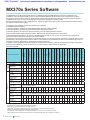
Multi-carrier IQproducer is software that generates the multi carrier signal based on waveform pattern of various
telecommunications systems.
√
√
Fading IQproducer is software that generates the Fading signal based on waveform pattern of various telecommunication systems.
√
√
• IQproducer™ is a registered trademark of Anritsu Corporation.
• MATLAB® is a registered trademark of The MathWorks, Inc.
• CDMA2000® is a registered trademark of the Telecommunications Industry Association (TIA-USA).
• WiMAX® is a trademark or registered trademark of WiMAX Forum.
• The Bluetooth® mark and logos are owned by Bluetooth SIG, Inc. and are used by Anritsu under license.
• Other companies, product names and service names are registered trademarks of their respective companies.
Product Brochure l
20
√
√
∗: Read the MX3701xxA IQproducer series catalog.
2
19
√
TD-SCDMA
18
√
GPS
Mobile WiMAX
(IEEE802.16e)
WLAN (IEEE802.11a/b/g)
Digital Broadcast (DVB-T/H)
17
√
Bluetooth
14 15, 16
√
√
Digital Broadcast
(BS/CS/CATV/ISDB-T)
ETC/DSRC
PDC
13
√
PHS
12
√
Advanced-PHS
10
√
Next-generation PHS (XGP)
GSM/EDGE
6
√
CDMA2000
6
√
CDMA2000 1xEV-DO
4
√
HSDPA/HSUPA
HSDPA (Test Model5)
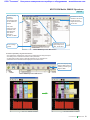
Page
Preinstalled
MX370001A
TD-SCDMA
MX370002A
Public Radio System
Standard accessories
AWGN
Standard accessories
W-CDMA
MX370101A
HSDPA/HSUPA
MX370102A
TDMA
MX370103A
CDMA2000 1xEV-DO
MX370104A
Multi-carrier
MX370105A
Mobile WiMAX
MX370106A
DVB-T/H
MX370107A
Fading
MX370108A
LTE FDD
MX370109A
XG-PHS
MX370110A
LTE TDD
W-CDMA
Waveform
pattern
Communication system
AWGN
Selection guide
√
ООО "Техэнком"
Контрольно-измерительные приборы и оборудование
www.tehencom.com
Product Brochure l
MX3700xxA
3
ООО "Техэнком"
Контрольно-измерительные приборы и оборудование
www.tehencom.com
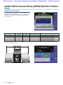
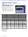
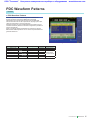
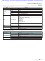
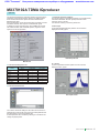
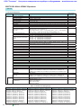
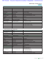
Additive White Gaussian Noise (AWGN) Waveform Patterns
Standard
■ AWGN Waveform Patterns
The AWGN waveform patterns listed in the table below are stored
on the MG3700A internal hard disk.
Signals for evaluating the UE receiver and transmitter performance
and modules, etc., are output by selecting one of these AWGN
waveform patterns.
Waveform Pattern Screen
MAX Peak/
RMS Ratio
>12 dB
>12 dB
3 dB Bandwidth
(MHz)
7.68
5.76
In-band Power
Conversion Ratio (dB)∗
3.01
1.76
AWGN_1.23MHz_x2
>12 dB
2.46
3.01
AWGN_1.23MHz_x1_5
>12 dB
3.69
1.76
Waveform Patterns
AWGN_3_84MHz_x2
AWGN_3_84MHz_x1_5
Evaluation
Added with W-CDMA UL signal to test dynamic range
Added with W-CDMA UL signal to test dynamic range
Added with reverse signals of CDMA2000 or
CDMA2000 1xEV-DO to test dynamic range
Added with reverse signals of CDMA2000 or
CDMA2000 1xEV-DO to test dynamic range
∗: T
he in-band power conversion ratio is the ratio of the system bandwidth of each communication system to the total power of the MG3700A output measured with
a power meter or equivalent device.
In-band AWGN Power Screen
4
Product Brochure l
MX3700xxA
ООО "Техэнком"
Контрольно-измерительные приборы и оборудование
www.tehencom.com
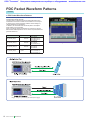
AWGN Waveform Patterns
Standard
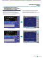
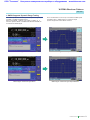
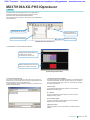
■ Using MG3700A Combine Function to
Output Wanted Signal + Interference Signal
(such as Modulation Signal + AWGN)
Because the MG3700A internal ARB memory can be partitioned
into two areas, separate waveforms can be saved in each memory
partition for either separate or combined output.
For example, if the Wanted Signal (W-CDMA, CDMA2000)
waveform is saved in one memory and the Interference Signal
(AWGN) is saved in the other, a signal combining both signals can
be output (top screens) from just one MG3700A unit.
Similarly, if a modulation signal is selected as the Interference
Signal, a single MG3700A can output a signal combining the
wanted signal and modulation signal (bottom screens).
Furthermore, digital signal processing of the S/N adjustments and
computations supports a superior level ratio.
Wanted Signal + AWGN Screen
Wanted Signal + AWGN Output Waveform
Wanted Signal + Interference Signal Screen
Wanted Signal + Interference Signal Screen Output Waveform
Product Brochure l
MX3700xxA
5
ООО "Техэнком"
Контрольно-измерительные приборы и оборудование
www.tehencom.com
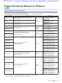
W-CDMA Waveform Patterns
Standard
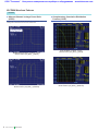
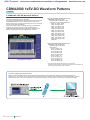
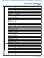
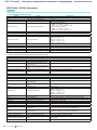
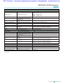
■ W-CDMA Waveform Patterns
The following W-CDMA waveform patterns are installed on the
internal hard disk when MG3700A Vector Signal Generator is
installed. Details for each pattern file is given on the next page.
• For Evaluating Base Station Transmitter Devices
(TS 25.141 Test Model 1 to 4)
TestModel_1_16DPCH
TestModel_1_32DPCH
TestModel_1_64DPCH
TestModel_1_64x2_10M
TestModel_1_64x2_15M
TestModel_2
TestModel_3_16DPCH
TestModel_3_32DPCH
TestModel_4
TestModel_5_2HSPDSCH
TestModel_5_4HSPDSCH
TestModel_5_8HSPDSCH
TestModel_6_8HSPDSCH
TestModel_1_64DPCHx2
TestModel_1_64DPCHx3
TestModel_1_64DPCHx4
DL_CPICH
• For Testing UE Receiver Performance
(TS 25.101 DL RMC 12.2 to 384 kbps)
DL_RMC_12_2kbps_RX
DL_RMC_12_2kbps
DL_RMC_12_2kbps_MIL
DL_RMC_12_2kbps_ACS
DL_RMC_64kbps
DL_RMC_144kbps
DL_RMC_384kbps
DL_AMR_TFCS1
DL_AMR_TFCS2
DL_AMR_TFCS3
DL_ISDN
DL_384kbps_Packet
DL_Interfere
DL_Interfere_ov3
P_CCPCH
Uplink and downlink W-CDMA modulation signals conforming to
the 3GPP (FDD) standards can be output simply by selecting the
waveform from the patterns on the MG3700A internal hard disk
without setting any complex 3GPP-compliant parameters.
• For Testing BS Receiver Performance
(TS 25.101/ 25.104 UL RMC 12.2 to 384 kbps)
UL_RMC_12_2kbps
UL_RMC_12_2kbps_ACS
UL_RMC_64kbps
UL_RMC_144kbps
UL_RMC_384kbps
UL_AMR_TFCS1
UL_AMR_TFCS2
UL_AMR_TFCS3
UL_ISDN
UL_64kbps_Packet
UL_Interfere
UL_Interfere_ov3
• For Evaluating UE Transmitter Devices
(TS 25.101 A2.1)
UL_RMC_12_2kbps_TX
6
Product Brochure l
MX3700xxA
Selecting Waveform Pattern
ООО "Техэнком"
Контрольно-измерительные приборы и оборудование
www.tehencom.com
W-CDMA Waveform Patterns
Standard
• W-CDMA Waveform Patterns List
Waveform Patterns
UL_RMC_12_2kbps
UL_RMC_12_2kbps_ACS∗1
UL_RMC_64kbps∗1
UL_RMC_144kbps∗1
UL_RMC_384kbps∗1
UL_AMR_TFCS1
UL_AMR_TFCS2
UL_AMR_TFCS3
UL_ISDN∗1
UL_64kbps_Packet
UL_Interfere
UL_Interfere_ov3
UL/DL
UL
Channel
DPCCH, DPDCH
DPCCH, DPDCH
DPCCH, DPDCH
DPCCH, DPDCH
DPCCH, DPDCH
DPCCH, DPDCH
DPCCH, DPDCH
DPCCH, DPDCH
DPCCH, DPDCH
DPCCH, DPDCH
DPCCH, DPDCH
DPCCH, DPDCH
3GPP (Release1999)
TS25.141 A.2
TS25.141 A.3
TS25.141 A.4
TS25.141 A.5
BS RX Test
TS25.944 4.1.2
TS25.141 I
UL_RMC_12_2kbps_TX
DPCCH, DPDCH
TS25.101 A.2.1
P_CCPCH∗2
DL_RMC_12_2kbps_RX∗2
DL_RMC_12_2kbps_ACS∗1
DL_RMC_12_2kbps_MIL∗2
DL_RMC_12_2kbps∗2
DL_RMC_64kbps∗2
DL_RMC_144kbps∗2
DL_RMC_384kbps∗2
DL_AMR_TFCS1∗2
DL_AMR_TFCS2∗2
DL_AMR_TFCS3∗2
DL_ISDN∗2
DL_384kbps_Packet∗2
DL_Interfere
DL_Interfere_ov3∗6
DL_CPICH
TestModel_1_16DPCH
TestModel_1_32DPCH
TestModel_1_64DPCH
TestModel_1_64DPCHx2∗4
TestModel_1_64DPCHx3∗4
TestModel_1_64DPCHx4∗4
TestModel_1_64x2_10M∗4, ∗5
TestModel_1_64x2_15M∗4, ∗5
TestModel_2
TestModel_3_16DPCH
TestModel_3_32DPCH
TestModel_4
P-CCPCH
P-CPICH, SCH, PICH, DPCH
P-CPICH, SCH, PICH, DPCH, P-CCPCH
P-CPICH, SCH, PICH, DPCH, OCNS
P-CPICH, SCH, PICH, DPCH, OCNS
P-CPICH, SCH, PICH, DPCH, OCNS
P-CPICH, SCH, PICH, DPCH, OCNS
P-CPICH, SCH, PICH, DPCH, OCNS
P-CPICH, SCH, PICH, DPCH, OCNS
P-CPICH, SCH, PICH, DPCH, OCNS
P-CPICH, SCH, PICH, DPCH, OCNS
P-CPICH, SCH, PICH, DPCH, OCNS
P-CPICH, SCH, PICH, DPCH, OCNS
P-CPICH, P-CCPCH, SCH, PICH, OCNS
P-CPICH, P-CCPCH, SCH, PICH, OCNS
P-CPICH
P-CPICH, P-CCPCH, SCH, PICH, S-CCPCH, 16DPCH
P-CPICH, P-CCPCH, SCH, PICH, S-CCPCH, 32DPCH
P-CPICH, P-CCPCH, SCH, PICH, S-CCPCH, 64DPCH
P-CPICH, P-CCPCH, SCH, PICH, S-CCPCH, 64DPCH
P-CPICH, P-CCPCH, SCH, PICH, S-CCPCH, 64DPCH
P-CPICH, P-CCPCH, SCH, PICH, S-CCPCH, 64DPCH
P-CPICH, P-CCPCH, SCH, PICH, S-CCPCH, 64DPCH
P-CPICH, P-CCPCH, SCH, PICH, S-CCPCH, 64DPCH
P-CPICH, P-CCPCH, SCH, PICH, S-CCPCH, 3DPCH
P-CPICH, P-CCPCH, SCH, PICH, S-CCPCH, 16DPCH
P-CPICH, P-CCPCH, SCH, PICH, S-CCPCH, 32DPCH
P-CCPCH, SCH
P-CPICH, P-CCPCH, SCH, PICH, S-CCPCH, 6DPCH,
HS-SCCH, 2HS-PDSCH
P-CPICH, P-CCPCH, SCH, PICH, S-CCPCH, 14DPCH,
HS-SCCH, 4HS-PDSCH
P-CPICH, P-CCPCH, SCH, PICH, S-CCPCH, 30DPCH,
HS-SCCH, 8HS-PDSCH
P-CPICH, P-CCPCH, SCH, PICH, S-CCPCH, 30DPCH,
HS-SCCH, 8HS-PDSCH
TS25.944 4.1.1∗3
TestModel_5_2HSPDSCH
TestModel_5_4HSPDSCH
TestModel_5_8HSPDSCH
TestModel_6_8HSPDSCH
DL
Evaluation
UE TX
Device Test
TS25.101 A.3.1
TS25.101 C.3.1
TS25.101 A.3.1/C3.2
TS25.101 A.3.2/C3.2
TS25.101 A.3.3/C3.2
TS25.101 A.3.4/C3.2
UE RX Test
TS25.944 4.1.1.3
TS25.101 C.3.2
TS25.101 C.4
–
TS25.141 6.1.1
BS TX
Device Test
TS25.141 8.2.0
∗1: T
he UL_RMC_12_2kbps_ACS, UL_RMC_64kbps, UL_RMC_144kbps, UL_RMC_384kbps, UL_ISDN and DL_RMC_12_2kbps_ACS patterns can be added to
the standard AWGN waveform pattern only when the optional ARB Memory Expansion 512 Msamples (Option 021/121) is installed.
∗2: S
ince waveform patterns (excluding DL_RMC12_2kbps_ACS) for the UE RX test do not include P-CCPCH, they must be used in combination with a P-CCPCH
waveform pattern.
∗3: A 12-bit SFN is added to the head of each BCH Transport block.
∗4: x2, x3, and x4 indicate multi-carrier 2, 3, and 4, respectively.
∗5: 10 M and 15 M indicate the multi-carrier interfrequency gap.
∗6: S
elect a waveform pattern generated using the W-CDMA waveform pattern generation function of the MG3700A IQproducer or by the MX370101A HSDPA
IQproducer (only the waveform patterns that can be configured using only one memory) for memory A on the MG3700A while selecting this pattern for memory
B to output a signal that is generated by adding the desired signal and the interference signal using baseband.
Product Brochure l
MX3700xxA
7
ООО "Техэнком"
Контрольно-измерительные приборы и оборудование
www.tehencom.com
W-CDMA Waveform Patterns
Standard
■ Adjacent Channel Leakage Power Ratio
(ACPR)
■ Complementary Cumulative Distribution
Function (CCDF)
The ACPR of a Vector Signal Generator is an important function for
testing device distortion and receiver interference.
W-CDMA ACPR (Test Model 1, 64 DPCH, 1 Carrier)
Waveform Pattern [Test_Model_1_64DPCH]
W-CDMA ACPR (Test Model 1, 64 DPCH, 4 Carrier)
Waveform Pattern [Test_Model_1_64DPCHx4]
8
Product Brochure l
MX3700xxA
CCDF (Test Model 1, 64 DPCH, 1 Carrier)
Waveform Pattern [Test_Model_1_64DPCH]
CCDF (Test Model 1, 64 DPCH, 4 Carrier)
Waveform Pattern [Test_Model_1_64DPCHx4]
ООО "Техэнком"
Контрольно-измерительные приборы и оборудование
www.tehencom.com
W-CDMA Waveform Patterns
Standard
■ AWGN Supports Dynamic Range Testing
The 3GPP specifications for testing receiver dynamic range require
a AWGN + W-CDMA modulation signal.
Either of the AWGN_3_84MHz_x2 or AWGN_3_84MHz_x1_5
waveform patterns stored on the MG3700A internal hard disk can
be used for the AWGN signal.
Since one MG3700A unit can output a combined W-CDMA uplink
modulation signal + AWGN signal, it is useful for simple
dynamic-range tests of base station receivers.
Wanted Signal + AWGN Screen
Wanted Signal + AWGN Output Waveform
Wanted Signal + Interference Signal Screen
Wanted Signal + Interference Signal Output Waveform
Product Brochure l
MX3700xxA
9
ООО "Техэнком"
Контрольно-измерительные приборы и оборудование
www.tehencom.com
CDMA2000 1xEV-DO Waveform Patterns
Standard
■ CDMA2000 1xEV-DO Waveform Patterns
The CDMA2000 1xEV-DO waveform patterns listed opposite are
stored on the MG3700A internal hard disk.
The 3GPP2 signals specified for testing receivers and transmitters
of CDMA2000 1xEV-DO access networks (base station) and
access terminal (AT) are output by selecting one of the 13 forward
and 10 reverse data rate patterns.
When multi-carrier signals, mixed idle and active signals and/or
multi-user signals are required, the optional MX370103A
CDMA2000 1xEV-DO IQproducer application, software can be
used to set parameters and generate waveform patterns.
• Access Terminal (AT) Receiver Test
CDMA2000 1xEV-DO forward
Baseband filter: IS-95 SPEC +EQ
Data: PN15 fix∗ (excluding FWD-Idle)
FWD_38_4kbps_16slot
FWD_76_8kbps_8slot
FWD_153_6kbps_4slot
FWD_307_2kbps_2slot
FWD_614_4kbps_1slot
FWD_307_2kbps_4slot
FWD_614_4kbps_2slot
FWD_1228_8kbps_1slot
FWD_921_6kbps_2slot
FWD_1843_2kbps_1slot
FWD_1228_8kbps_2slot
FWD_2457_6kbps_1slot
FWD_Idle
• Access Network (AN) Receiver Test
Selecting Waveform Pattern
CDMA2000 1xEV-DO Reverse
Baseband filter: IS-95 SPEC
Data: PN9 fix∗
RVS_9_6kbps_RX
RVS_19_2kbps_RX
RVS_38_4kbps_RX
RVS_76_8kbps_RX
RVS_153_6kbps_RX
RVS_9_6kbps_TX
RVS_19_2kbps_TX
RVS_38_4kbps_TX
RVS_76_8kbps_RT
RVS_153_6kbps_RT
∗: T
his displays the delimited PN sequence for each packet.
Therefore, the PN sequence is discontinuous between the end data of one
packet and the header data of the next packet.
• Access Terminal (AT) Receiver Test
3GPP2 C.S0033 standard receiver tests (PER: Packet Error Rate) can be performed by selecting a forward signal pattern for
testing the AT. Since protocols are not supported for the access network simulator and all transmission channels are traffic, while all
other channels (Sync, etc.) are unsupported., an external controller (PC) must be used to control the AT and calculate the PER.
10
Product Brochure l
MX3700xxA
ООО "Техэнком"
Контрольно-измерительные приборы и оборудование
www.tehencom.com
CDMA2000 1xEV-DO Waveform Patterns
Standard
• Access Network (AN) Receiver Test
GPP2 C.S0032 standard receiver tests (PER: Packet Error Rate) can be performed by selecting a reverse signal pattern required for
testing the AN. Since access terminal simulator protocols are unsupported, an external controller must be used to control the AN and
calculate PER.
∗ Trigger: Timing for synchronizing start of frame (frame trigger)
∗ Clock: Clock for synchronizing chip rate of 1.2288 Mcps (11 x 1.2288 MHz or 5 MHz/10 MHz)
■ AWGN Supports Dynamic Range Testing
The 3GPP2 specifications require a 1xEV-DO modulation signal +
AWGN for performing the receiver dynamic range test.
Either of the AWGN_1.23MHz_x2 or AWGN_1.23MHz_x1_5
waveform patterns stored on the MG3700A internal hard disk can
be used for the AWGN signal.
Wanted Signal + AWGN Screen
Since one MG3700A unit can output a combined CDMA2000 uplink
modulation signal + AWGN signal, it is useful for simple dynamicrange tests of an AN receiver.
Wanted Signal + AWGN Output Waveform
Product Brochure l
MX3700xxA
11
ООО "Техэнком"
Контрольно-измерительные приборы и оборудование
www.tehencom.com
CDMA2000 Waveform Patterns
Standard
■ CDMA2000 Waveform Patterns
The CDMA2000 waveform patterns listed in the table below are
stored on the MG3700A internal hard disk.
The 3GPP2 C.S0002-0-2-specified CDMA2000 modulation signals
are output by selecting one of these CDMA2000 waveform
patterns.
Reverse channel signals are output by channel coding
(convolutional coding, etc.) 4-frame length PN9 fix∗1 data, which is
useful for measuring the Frame Error Rate (FER)∗2 of base stations
and evaluating devices.
∗1: S
ince the data length is not an integer multiple of the PN sequence length
(511 bits for PN9), the PN sequence becomes discontinuous at the end.
∗2: T
his is the case when the timing signal and 1.2288 Mcps x 11 clock
signal (or 5 or 10 MHz reference clock) can be input from the test target
base station to the MG3700A in order to synchronize the frame start point
and chip clock.
Selecting Waveform Pattern
Waveform Patterns
RVS_RC1_FCH
RVS_RC2_FCH
RVS_RC3_FCH
RVS_RC3_FCH_SCH
RVS_RC3_DCCH
RVS_RC4_FCH
FWD_RC1-2_9channel
FWD_RC3-5_9channel
Waveform Patterns
RVS_RC1_FCH
RVS_RC2_FCH
RVS_RC3_FCH
RVS_RC3_FCH_SCH
RVS_RC3_DCCH
RVS_RC4_FCH
System
CDMA2000 1XRTT RC1 Reverse
CDMA2000 1XRTT RC2 Reverse
CDMA2000 1XRTT RC3 Reverse
CDMA2000 1XRTT RC3 Reverse
CDMA2000 1XRTT RC3 Reverse
CDMA2000 1XRTT RC4 Reverse
CDMA2000 1XRTT RC1, RC2 Forward
CDMA2000 1XRTT RC3, RC4, RC5 Forward
R-FCH
R-FCH
R-PICH
R-FCH
R-PICH
R-FCH
R-SCH
R-PICH
R-DCCH
R-PICH
R-FCH
Waveform Patterns
FWD_RC1-2_9channel
FWD_RC3-5_9channel
F-PICH
F-SyncCH
PagingCH
F-FCH x6
F-PICH
F-SyncCH
PagingCH
F-FCH x6
R-PICH (Reverse Pilot Channel)
R-FCH (Reverse Fundamental Channel)
R-SCH (Reverse Supplemental Channel)
R-DCCH (Reverse Dedicated Control Channel)
F-PICH (Forward Pilot Channel)
F-SyncCH (Forward Sync Channel)
PagingCH (Paging Channel)
F-FCH (Forward Fundamental Channel)
12
Product Brochure l
MX3700xxA
Frame Coding
Coded
Coded
Coded
Coded
Coded
Coded
Spreading only
Spreading only
Walsh Code
Code Power
0
4
0
4
2
0
8
0
4
Walsh Code
0
32
1
8−13
0
32
1
8−13
–5.278 dB
–1.528 dB
–7.5912 dB
–3.8412 dB
–3.8412 dB
–5.278 dB
–1.528 dB
–5.278 dB
–1.528 dB
Code Power
–7.0 dB
–13.3 dB
–7.3 dB
–10.3 dB
–7.0 dB
–13.3 dB
–7.3 dB
–10.3 dB
Symbol Data
FCH 9.6 kbps
FCH 14.4 kbps
PICH, FCH 9.6 kbps
PICH, FCH 9.6 kbps, SCH 9.6 kbps
PICH, DCCH 9.6 kbps
PICH, FCH 14.4 kbps
PICH, SyncCH, PagingCH, FCH 19.2 ksps x 6
PICH, SyncCH, PagingCH, FCH 38.4 ksps x 6
Data Rate
9.6 kbps
14.4 kbps
N/A
9.6 kbps
N/A
9.6 kbps
9.6 kbps
N/A
9.6 kbps
N/A
14.4 kbps
Symbol Rate
N/A
4.8 kbps
19.2 kbps
19.2 kbps
N/A
4.8 kbps
19.2 kbps
38.4 kbps
Data
PN9fix∗
PN9fix∗
All“0”
PN9fix∗
All“0”
PN9fix∗
PN9fix∗
All“0”
PN9fix∗
All“0”
PN9fix∗
Symbol Data
All“0”
PN9fix∗
PN9fix∗
PN9fix∗
All“0”
PN9fix∗
PN9fix∗
PN9fix∗
ООО "Техэнком"
Контрольно-измерительные приборы и оборудование
www.tehencom.com
GSM/EDGE Waveform Patterns
Standard
■ GSM/EDGE Waveform Patterns
The GSM/EDGE waveform patterns listed in the table below are
installed on the internal hard disk when MG3700A Vector Signal
Generator is installed. Details for the pattern files are given below.
Signals for testing receivers and for evaluating devices in a GSM/
EDGE system are output by selecting one of these GSM/EDGE
waveform patterns.
• GMSK_PN9, 8PSK_PN9
PN9 data which doesn't have slot format is inserted.
• GMSK_TN0, 8PSK_TN0
PN9 data is inserted into the entire area of the slots, except the
guard. The PN9 data in each slot is continuous.
• NB_GMSK, NB_ALL_GMSK, NB_8PSK, NB_ALL_8PSK
PN9 data is inserted into the normal burst encrypted bit area.
The PN9 data in the slots is continuous.
Selecting Waveform Pattern
• TCH_FS
Supports Speech channel at full rate (TCH/FS) specified in Section
3.1 of 3GPP TS05.03
• CS-1_1 (4)_SLOT (_4SLOT )
Supports packet data block type 1 (CS-4) and 4 (CS-1) specified in
Section 5.1 of 3GPP TS05.03
• DL (UL)_MCS-1 (5, 9)_1SLOT (_4SLOT)
Supports packet data block types 5 (MCS-1), 9 (MCS-5), and 13
(MCS-9) specified in Section 5.1 of 3GPP TS05.03
Waveform Patterns
GMSK_PN9
8PSK_PN9
GMSK_TN0
8PSK_TN0
NB_GMSK
NB_ALL_GMSK
NB_8PSK
NB_ALL_8PSK
TCH_FS
CS-1_1SLOT
CS-4_1SLOT
DL_MCS-1_1SLOT
UL_MCS-1_1SLOT
DL_MCS-5_1SLOT
UL_MCS-5_1SLOT
DL_MCS-9_1SLOT
UL_MCS-9_1SLOT
DL_MCS-9_4SLOT
UL_MCS-9_4SLOT
Uplink/Downlink
Uplink/Downlink
Uplink/Downlink
Uplink/Downlink
Uplink/Downlink
Uplink/Downlink
Uplink/Downlink
Uplink/Downlink
Uplink/Downlink
Uplink/Downlink
Uplink/Downlink
Uplink/Downlink
Uplink/Downlink
Uplink/Downlink
Uplink/Downlink
Uplink/Downlink
Uplink/Downlink
Uplink/Downlink
Uplink/Downlink
Uplink/Downlink
Data
PN9
∗1
PN9∗2
PN9∗3
PN9∗4
Output Slot
–
–
TN0
TN0
TN0
All Slots
TN0
All Slots
TN0
TN0
TN0
TN0
TN0
TN0
TN0
TN0
TN0
TN0, 1, 2, 3
TN0, 1, 2, 3
Communications
–
–
–
–
GSM
GPRS
EDGE
∗1: PN9 data is inserted into the entire area that does not have the slot format.
∗2: PN9 data is inserted into the entire area of the slots, except the guard.
∗3: PN9 data is inserted into the normal burst encrypted bit area.
∗4: The bit string channel-coded for PN9 data is inserted into the normal burst encrypted bit area.
Product Brochure l
MX3700xxA
13
ООО "Техэнком"
Контрольно-измерительные приборы и оборудование
www.tehencom.com
PHS Waveform Patterns
Standard
■ PHS Waveform Patterns
The PHS waveform patterns listed in the table below are stored on
the MG3700A internal hard disk.
The RCR STD-28-specified signals for testing CS (base station)
and PS (mobile station) receivers are output by selecting one of
these PHS waveform patterns without setting any complex RCR
STD-28 parameters.
When a signal with different parameters is required, the optional
MX370102A TDMA IQproducer can be used to set parameters and
generate waveforms.
Waveform Patterns
PI_4_DQPSK_PN9
PI_4_DQPSK_PN15
PI_4_DQPSK_ALL0
Uplink/Downlink
–
–
–
Scramble
OFF
OFF
OFF
DL_TCH_Slot_1
Uplink/Downlink
OFF
UL_TCH_Slot_1
Uplink/Downlink
OFF
–
–
CW
Output Slot
No frame
No frame
No frame
Slot 1: TCH
Slot 2 to 4: off
Slot 1: TCH
Slot 2 to 4: off
–
∗ Trigger: Timing for synchronizing frames (frame trigger)
14
Product Brochure l
MX3700xxA
Selecting Waveform Pattern
ООО "Техэнком"
Контрольно-измерительные приборы и оборудование
www.tehencom.com
PDC Waveform Patterns
Standard
■ PDC Waveform Patterns
Waveform patterns for the Wanted Signals and Interference
Signals required to execute the ARIB STD-27-specified
transmission and reception tests are stored on the MG3700A
internal hard disk. and can be output without requiring options (but
check the parameters on the next page first).
Waveform patterns to output uplink/downlink Slot 0 data only and
unframed waveform pattern for interference signals are provided for
full rate and half rate.
When a signal with different parameters is required, the optional
MX370102A TDMA IQproducer can be used to set parameters and
generate waveforms.
Selecting Waveform Pattern
Waveform Patterns
PI_4_DQPSK_PN9
PI_4_DQPSK_PN15
DL_Full_Rate_Slot0
DL_Half_Rate_Slot0
UL_Full_Rate_Slot0
UL_Half_Rate_Slot0
CW
Uplink/Downlink
–
–
Uplink/Downlink
Uplink/Downlink
Uplink/Downlink
Uplink/Downlink
–
Half Rate/Full Rate
–
–
Full rate
Half rate
Full rate
Half rate
–
Output Slot
No frame
No frame
Slot 0 only
Slot 0 only
Slot 0 only
Slot 0 only
–
Evaluation
TX Device Test
Interfering Signal
Wanted Signal
for Receiver Test
Interfering Signal
Product Brochure l
MX3700xxA
15
ООО "Техэнком"
Контрольно-измерительные приборы и оборудование
www.tehencom.com
PDC Packet Waveform Patterns
Standard
■ PDC Packet Waveform Patterns
The four waveform patterns listed in the table below are stored on
the MG3700A internal hard disk.
The RCR STD-27-specified signals for testing base station and
mobile station receivers for UPCH communications can be output
by selecting one of these waveform patterns without setting any
complex RCR STD-27 parameters.
In addition, the Downlink3 data rate UPCH pattern and Uplink1
UPCH pattern can be switched.
When a signal with different parameters is required, the optional
MX370102A TDMA IQproducer can be used to set parameters and
generate waveforms.
Waveform Patterns
Uplink/Downlink
DL_Packet_Slot_0
Uplink/Downlink
DL_Packet_Slot_01
Uplink/Downlink
DL_Packet_Slot_all
Uplink/Downlink
UL_Packet_Slot_0
Uplink/Downlink
Output Slot
Slot 0=UPCH
Slot 1=IDLE (all "1")
Slot 2=IDLE (all "1")
Slot 0=UPCH
Slot 1=UPCH
Slot 2=IDLE (all "1")
Slot 0=UPCH
Slot 1=UPCH
Slot 2=UPCH
Slot 0=UPCH
Slot 1=Transmit off
Slot 2=Transmit off
∗ Trigger: Timing for synchronizing sub frames (frame trigger)
16
Product Brochure l
MX3700xxA
Selecting Waveform Pattern
ООО "Техэнком"
Контрольно-измерительные приборы и оборудование
www.tehencom.com
Digital Broadcast Waveform Patterns
Standard
■ Digital Broadcast Waveform Patterns
The BS/CS/CATV/ISDB-T waveform patterns listed in the table below are stored on the MG3700A internal hard disk and signals for testing
devices are output by selecting one of these waveform patterns.
There is also a pattern for evaluating ISDB-T video and audio as well as for simple BER measurements.
Waveform Patterns
Outline
BS_1ch
Physical layer waveform pattern of digital BS broadcast
For device evaluation
CS_1ch
Physical layer waveform pattern of digital CS broadcast
For device evaluation
CATV_AnnexC_1ch
Physical layer waveform pattern for CATV (ITU-T J83 Annex C)
For device evaluation
ISDBT_1layer_1ch
ISDBT_2layer_1ch
ISDBT_2layer_Movie
ISDBT_2layer_Movie2
1channel
PN23fix∗1
Modulation only
Physical layer waveform pattern for ISDB-T
For device evaluation
1 channel
PN23fix∗1
Pilot Signal
With TMCC
Waveform pattern for ISDB-T partial reception
For evaluating video and audio data of terminals
40-frame waveform length
1 channel
For video and audio
Waveform pattern for ISDB-T partial reception
For simple BER measurement.
4-frame waveform length
1 channel
For simple BER
Waveform pattern for ISDB-Tsb partial reception∗2
For evaluation video and audio data of terminals.
68-frame waveform length
1 channel
For video and audio
Waveform pattern for ISDB-Tsb partial reception∗2
For simple BER measurement.
4-frame waveform length
1 channel
For simple BER
ISDBT_2layer_Coded
ISDBT_QPSK_1_2
ISDBT_QPSK_2_3
ISDBT_16QAM_1_2
ISDBT_QPSK_2_3_TI4
ISDBTsb_Movie
ISDBTsb_QPSK_1_2
ISDBTsb_QPSK_2_3
ISDBTsb_16QAM_1_2
Parameter
Roll-off factor: 0.35
Nyquist Bandwidth: 28.86 MHz
Modulation: QPSK
Roll-off factor: 0.35
Nyquist Bandwidth: 21.096 MHz
Modulation: QPSK
Roll-off factor: 0.13
Nyquist Bandwidth: 5.274 MHz
Modulation: 64QAM
Mode: 3, GI: 1/8
A-Layer: 13seg, 64QAM
Mode: 3, GI: 1/8
A-Layer: 1seg, QPSK
B-Layer: 12seg, 64QAM
Mode: 3, GI: 1/8
A-Layer: 1seg, QPSK, CR=2/3, TI=2
B-Layer: 12seg, 64QAM, CR=7/8, TI=2
Mode: 3, GI: 1/8
A-Layer: 1seg, QPSK, CR=2/3, TI=4
B-Layer: 12seg, 64QAM, CR=3/4, TI=2
Mode: 3, GI: 1/8
A-Layer: 1seg, QPSK, CR=2/3, TI=2
B-Layer: 12seg, 64QAM, CR=7/8, TI=2
Mode: 3, GI: 1/8
A-Layer: 1seg, QPSK, CR=1/2, TI=0
B-Layer: 12seg, 64QAM, CR=7/8, TI=1
Mode: 3, GI: 1/8
A-Layer: 1seg, QPSK, CR=2/3, TI=0
B-Layer: 12seg, 64QAM, CR=7/8, TI=1
Mode: 3, GI: 1/8
A-Layer: 1seg, 16QAM, CR=1/2, TI=0
B-Layer: 12seg, 64QAM, CR=7/8, TI=1
Mode: 3, GI: 1/8
A-Layer: 1seg, QPSK, CR=2/3, TI=4
B-Layer: 12seg, 64QAM, CR=3/4, TI=2
Mode: 3, GI: 1/8
A/B-Layer: QPSK, CR=1/2, TI=4
Seg#1 to #5: 8-segment concatenation
transmission in 1-segment format
Seg#6 to #8: 8-segment concatenation
transmission in 3-segment format
Mode: 3, GI: 1/8
A/B-Layer: QPSK, CR=1/2, TI=0
Seg#1 to #5: 8-segment concatenation
transmission in 1-segment format
Seg#6 to #8: 8-segment concatenation
transmission in 3-segment format
Mode: 3, GI: 1/8
A/B-Layer: QPSK, CR=2/3, TI=0
Seg#1 to #5: 8-segment concatenation
transmission in 1-segment format
Seg#6 to #8: 8-segment concatenation
transmission in 3-segment format
Mode: 3, GI: 1/8
A/B-Layer: 16QAM, CR=1/2, TI=0
Seg#1 to #5: 8-segment concatenation
transmission in 1-segment format
Seg#6 to #8: 8-segment concatenation
transmission in 3-segment format
∗1: T
he PN sequence is discontinuous at the waveform pattern connection.
This cannot be used to measure BER (PN23) although it can be used for simple BER measurement.
∗2: It is not guaranteed that any receiver can receive a waveform with this length.
Product Brochure l
MX3700xxA
17
ООО "Техэнком"
Контрольно-измерительные приборы и оборудование
www.tehencom.com
WLAN Waveform Patterns
Standard
■ WLAN Waveform Patterns
The WLAN (IEEE802.11a/b/g) waveform patterns listed in the table
below are stored on the MG3700A internal hard disk.
Signals for testing the receiver and transmitter of a terminal or
module can be output by selecting one of these patterns.
The waveform patterns shown below are the signals for one
packet. When a waveform pattern is selected, the signal is output in
an endless loop. To stop the signal at a fixed number of packets,
use the IQproducer Combination File Edit function to generate the
sequence file first and select it using the MG3700A (see Section
4.8 of the IQproducer manual).
Selecting Waveform Pattern
• IEEE_802.11a/802.11g (ERP-OFDM) Waveform Patterns List
Waveform Patterns
11a_OFDM_6Mbps
11a_OFDM_9Mbps
11a_OFDM_9Mbps_PN9∗1
11a_OFDM_12Mbps
11a_OFDM_18Mbps
11a_OFDM_18Mbps_PN9∗1
11a_OFDM_24Mbps
11a_OFDM_36Mbps
11a_OFDM_36Mbps_PN9∗1
11a_OFDM_48Mbps
11a_OFDM_54Mbps
11a_OFDM_54Mbps_PN9∗1
11a_OFDM_54Mbps_ACP∗2
Data Rate
(Mbps)
6
9
9
12
18
18
24
36
36
48
54
54
54
Modulation
Coding Rate
BPSK
BPSK
BPSK
QPSK
QPSK
QPSK
16QAM
16QAM
16QAM
64QAM
64QAM
64QAM
64QAM
1/2
3/4
3/4
1/2
3/4
3/4
1/2
3/4
3/4
2/3
3/4
3/4
3/4
Coding Bits per
Sub-carrier
1
1
1
2
2
2
4
4
4
6
6
6
6
Coding Bits per
OFDM Symbol
48
48
48
96
96
96
192
192
192
288
288
288
288
Data Bits per
OFDM Symbol
24
36
36
48
72
72
96
144
144
192
216
216
216
Coding Bits per
Sub-carrier
1
1
2
2
4
4
6
6
Coding Bits per
OFDM Symbol
48
48
96
96
192
192
288
288
Data Bits per
OFDM Symbol
24
36
48
72
96
144
192
216
∗1: Continuous PN9 data between PSDUs
∗2: Improved ACPR
• IEEE_802.11b Waveform Patterns List
Waveform Patterns
11b_DSSS_1Mbps
11b_DSSS_2Mbps
11b_DSSS_2Mbps_PN9∗1
11b_CCK_5_5Mbps
11b_CCK_11Mbps
11b_CCK_11Mbps_PN9∗1
11b_CCK_11Mbps_ACP∗2
Spreading, Coding
DSSS, 11 chip Barker Code
DSSS, 11 chip Barker Code
DSSS, 11 chip Barker Code
CCK
CCK
CCK
CCK
Modulation
DBPSK
DQPSK
DQPSK
DQPSK
DQPSK
DQPSK
DQPSK
• IEEE_802.11g (DSSS-OFDM) Waveform Patterns List
Waveform Patterns
11g_DSSS_OFDM_6Mbps
11g_DSSS_OFDM_9Mbps
11g_DSSS_OFDM_12Mbps
11g_DSSS_OFDM_18Mbps
11g_DSSS_OFDM_24Mbps
11g_DSSS_OFDM_36Mbps
11g_DSSS_OFDM_48Mbps
11g_DSSS_OFDM_54Mbps
18
Product Brochure l
MX3700xxA
Data Rate
(Mbps)
6
9
12
18
24
36
48
54
Modulation
Coding Rate
BPSK
BPSK
QPSK
QPSK
16QAM
16QAM
64QAM
64QAM
1/2
3/4
1/2
3/4
1/2
3/4
2/3
3/4
ООО "Техэнком"
Контрольно-измерительные приборы и оборудование
www.tehencom.com
Bluetooth Waveform Patterns
Standard
■ Bluetooth Waveform Patterns
The Bluetooth waveform patterns listed in the table below are
stored on the MG3700A internal hard disk.
Selecting one of these waveform patterns outputs the best signal
for the evaluation.
• POLL:
This is used for operation checks and PER measurement of mobile
terminals with Bluetooth.
• No Packet Format (PN9, PN15):
This is used for BER measurement of mobile terminals and
modules with Bluetooth.
• DH1, DH3, DH5:
This is used in combination with an external demodulator for
loopback tests (no FEC) of mobile terminals and modules with
Bluetooth.
Waveform Timing Chart
Waveform Patterns
DH1∗1
DH3∗1
DH5∗1
DH3_3SlotOff∗1
DH5_5SlotOff∗1
POLL
2-DH1∗1
2-DH3∗1
2-DH5∗1
2-DH3_3SlotOff∗1
2-DH5_5SlotOff∗1
3-DH1∗1
3-DH3∗1
3-DH5∗1
3-DH3_3SlotOff∗1
3-DH5_5SlotOff∗1
GFSK-PN9∗2
GFSK-PN15∗3
PI_4_DQPSK-PN9∗2
PI_4_DQPSK-PN15∗3
8DPSK-PN9∗2
8DPSK-PN15∗3
Data rate
(Mbps)
1
1
1
1
1
1
2
2
2
2
2
3
3
3
3
3
1
1
2
2
3
3
Payload Modulation
Filter
Packet type
GFSK∗4
GFSK∗4
GFSK∗4
GFSK∗4
GFSK∗4
GFSK∗4
π/4-DQPSK
π/4-DQPSK
π/4-DQPSK
π/4-DQPSK
π/4-DQPSK
8-DPSK
8-DPSK
8-DPSK
8-DPSK
8-DPSK
GFSK∗4
GFSK∗4
π/4-DQPSK
π/4-DQPSK
8-DPSK
8-DPSK
Gaussian∗5
Gaussian∗5
Gaussian∗5
Gaussian∗5
Gaussian∗5
Gaussian∗5
Root Nyquist∗6
Root Nyquist∗6
Root Nyquist∗6
Root Nyquist∗6
Root Nyquist∗6
Root Nyquist∗6
Root Nyquist∗6
Root Nyquist∗6
Root Nyquist∗6
Root Nyquist∗6
Gaussian∗5
Gaussian∗5
Root Nyquist∗6
Root Nyquist∗6
Root Nyquist∗6
Root Nyquist∗6
DH1
DH3
DH5
DH3
DH5
POLL
2-DH1
2-DH3
2-DH5
2-DH3
2-DH5
3-DH1
3-DH3
3-DH5
3-DH3
3-DH5
No packet format
No packet format
No packet format
No packet format
No packet format
No packet format
∗1: PN9 data is inserted into the payload body.
∗2: PN9 data is inserted into all areas that do not have a packet format.
∗3: PN15 data is inserted into all areas that do not have a packet format.
∗4: Modulation index=0.32
∗5: Bandwidth time (BT)=0.5
∗6: Roll-off rate ß=0.4
The Dirty Signal required for evaluating reception characteristics is supplied as a software download from the Anritsu website.Use of this software download
requires free user registration first.
oftware download site address
S
•https://www1.anritsu.co.jp/Download/MService/Login.asp
Product Brochure l
MX3700xxA
19
ООО "Техэнком"
Контрольно-измерительные приборы и оборудование
www.tehencom.com
GPS Waveform Patterns
Standard
■ GPS Waveform Patterns
The four GPS waveform patterns listed below are stored on the
MG3700A internal hard disk.
Selecting one of these waveform patterns outputs the best signal
for the evaluation.
• SYNC_ADJ
This is used for synchronization adjustment of mobile terminals with
GPS.
• TLM, TLM_PARITY
This is used for receiver sensitivity measurement and operation
checks of mobile terminals with GPS.
• PARITY
This is used for detecting the parity of mobile terminals with GPS.
• PN9
This is used for BER measurement during device evaluation.
Waveform Patterns
SYNC_ADJ
∗1
Main Usage
Synchronization
adjustment∗2
TLM∗3
Sensitivity test
PN9
BER
measurement
PARITY
Parity detection
TLM_PARITY
Sensitivity test
Data0, Data1, Data10,
Data1C
Synchronization
adjustment
Selecting Waveform Pattern
Outline of Data
Consists of TLM, HOW, and default navigation data, formatted according to subframe configuration prescribed
in GLOBAL POSITIONING SYSTEM STANDARD POSITIONING SERVICE SIGNAL SPECIFICATION
Consists of TLM, HOW, and default navigation data, formatted according to subframe configuration prescribed
in GLOBAL POSITIONING SYSTEM STANDARD POSITIONING SERVICE SIGNAL SPECIFICATION
Consecutive PN9 data not configured in subframe format
Configured in Word format prescribed in GLOBAL POSITIONING SYSTEM STANDARD POSITIONING
SERVICE SIGNAL SPECIFICATION
One Word consists of 24-bit PN9 fix data and 6-bit parity bit data.
Consists of TLM, HOW, and Nav Data, formatted according to subframe configuration prescribed in GLOBAL
POSITIONING SYSTEM STANDARD POSITIONING SERVICE SIGNAL SPECIFICATION. Random data is
inserted into the Nav Data part of Word3 to Word10.
One period is configured with 5 subframes.
Used in combination with SYNC_ADJ. These waveform patterns are automatically loaded into the memory
when SYNC_ADJ is loaded into the memory.
Users do not have to perform loading and selecting of these waveform patterns, because these waveform
patterns are automatically selected when SYNC_ADJ is selected.
∗1: U
se SYNC_ADJ in combination with Data0, Data1, and Data10. When selecting a file, press the Baseband key on the MG3700A to set Pattern Combination to
Defined. Refer to the MG3700A Vector Signal Generator Operation Manual (main frame) for details about how to make the settings.
∗2: T
he repeatability of the subframe output timing of the RF output versus external start trigger input is reduced to 10 ns max.
∗3: W
hen executing a Doppler test, change the RF frequency and sampling clock at the same rate.The sampling clock when the Doppler frequency is 0 Hz is 4.092
MHz. For example, when applying a +4 kHz Doppler frequency, the following expression establishes (providing the sampling clock as "CLK"): (1575.42 MHz + 4
kHz)/1575.42MHz = CLK/4.092 MHz then: CLK = 4.09201039 MHz.
Refer to the MG3700A Operation Manual (Mainframe) for RF frequency and sampling clock settings.
SYNC_ADJ output timing
20
Product Brochure l
MX3700xxA
ООО "Техэнком"
Контрольно-измерительные приборы и оборудование
www.tehencom.com
MX370001A TD-SCDMA Waveform Pattern
Optional
■ TD-SCDMA Waveform Patterns
Signals for the 3GPP 1.28 Mcps TDD options can be output by
installing the MX370001A TD-SCDMA Waveform Pattern option in
the MG3700A.
Evaluating BS Transmitter • For Evaluating UE Receiver
• For
BS_DL RMC 1Code
BS_DL RMC 1Code+P-CCPCH
BS_DL RMC 8Code
BS_DL RMC 10Code
• For Evaluating BS Receiver
UE_DL RMC 12.2kbps
UE_DL RMC 12.2kbps+OCNS
UE_DL RMC 64kbps+OCNS
UE_DL RMC 144kbps+OCNS
UE_DL RMC 384kbps
■ Simple Operation and
Fast Signal Pattern Change
Typical waveforms specified in 3GPP, such as the reference
management channel, are output just by selecting the waveform
pattern stored on the MG3700A internal hard disk without setting
any complex TD-SCDMA parameters.
BS_UL RMC 12.2kbps (Single)
BS_UL RMC 12.2kbps+OCNS
BS_UL RMC 64kbps+OCNS
BS_UL RMC 144kbps+OCNS
BS_UL RMC 384kbps
• Waveform Patterns for Evaluating BS Transmitters
Target
Test Signal
Waveform Patterns
Test
Standard
DwPTS/UpPTS
SYNC_DL/UL
NUMBER (quadruples)
P-CCPCH
Scrambling Code
Midamble ID
Maximum User (user number)
Spread Factor
TimeSlot Number
Number of DPCH0
DPCH Channelizaton Codes
DPCH0 Channelizaton Codes
Data: DPCH0
Data: other channel
Σ DPCH_Ec/Ior [dB]
DPCH0_Ec/Ior [dB]
DPCH Channelizaton Codes
Power [dB]/1 ch
DPCH0 Channelizaton Codes
Power [dB]/1 ch
rmc_1 code_bs_dl
Freq/Power Ctrl/
Minimum Pwr
BS Transmitter Test (DL)
BS
BS-DL RMC
rmc_P-CCPCH_bs_dl
rmc_8 code_bs_dl
OBW/OnOffRatio/
P-CCPCH Pwr
Max Pwr/spurious/
ACLR/TxIM
TS25.142
rmc_10 code_bs_dl
EVM/
Peak code domain err
SYNC_DL #0
(S1)
SYNC_DL #0
(S1)
SYNC_DL #0
(S1)
SYNC_DL #0
(S1)
–
0
0
2 (1)
16
4, 5, 6
–
C (i, 16), i=1
–
PN9
–
0
–
add
0
0
8 (1)
16
0
–
C (i, 16), i=1, 2
–
–
P-CCPCH: All 0
–
–
–
0
0
2 (1)
16
4, 5, 6
0
C (i, 16),1≤i≤8
–
PN9
–
0
–
–
0
0
2 (1)
16
4, 5, 6
0
C (i, 16), 1≤i≤10
–
PN9
–
0
–
0
–
–9
–10
–
–
–
–
Product Brochure l
MX3700xxA
21
ООО "Техэнком"
Контрольно-измерительные приборы и оборудование
www.tehencom.com
MX370001A TD-SCDMA Waveform Pattern
Optional
• Waveform Patterns for Evaluating BS Receivers
Target
Test Signal
Waveform Patterns
Test
Standard
DwPTS/UpPTS/SYNC_DL/
UL NUMBER (quadruples)
P-CCPCH
Scrambling Code
Midamble ID
Maximum User
(user number)
Spread Factor
TimeSlot Number
Number of DPCH
rmc12_2k_bs_ul
RS/Min. Input Lev./
Dynamic range/ACS/
Blocking/Rx IM
rmc12k_ocns_bs_ul
Performance Req.
Performance Req.
rmc144k_bs_ul
rmc384k_bs_ul
Performance Req.
Performance Req.
TS25.142
–
–
–
–
–
–
0
0
–
0
0
–
0
0
–
0
0
–
0
0
2 (1)
2 (1)
2 (1)
2 (1)
2 (1)
8
1
0
8
1
4
2, 8
1
1
2, 8
1, 2
1
8, 2
1, 2, 3, 4
0
C (i, 2), i=1
C (i, 8), i=5
–
PN9
–
0
–
C (i, 2)=−6.99
C (i, 8)=−0.97
DPCH Channelizaton Codes
C (i, 8), i=1
C (i, 8), i=1
C (i, 2), i=1
C (i, 2), i=1
DPCH0 Channelizaton Codes
Data: DPCH0
Data: other channel
Σ DPCH_Ec/Ior [dB]
DPCH0_Ec/Ior [dB]
DPCH Channelizaton Codes
Power [dB]/1ch
DPCH0 Channelizaton Codes
Power [dB]/1ch
–
PN9
–
0
–
C (i, 8), 2≤i≤5
PN9
PN9
–
–7
C (i, 8), i=5
PN9
PN9
–
–7
C (i, 8), i=5
PN9
PN9
–
–7
0
–7
–0.97
–0.97
–
–7
–7
–7
–
rmc144k_ocns_ue_dl
rmc384k_ue_dl
Performance Req.
Performance Req.
• Waveform Patterns for Evaluating UE Receivers
Target
Test Signal
Waveform Patterns
Test
22
BS Receive Test (UL)
BS
BS-UL RMC
rmc64k_ocns_bs_ul
rmc12_2k_ue_dl
RS/Min. Input Lev./
ACS/Blocking/
Spur.Resp. /Inter Mod
Standard
DwPTS/UpPTS
SYNC_DL/UL
NUMBER (quadruples)
P-CCPCH
Scramblng Code
Midamble ID
Maximum User
(user number)
Spread Factor
TimeSlot Number
Number of DPCH0
DPCH Channelizaton Codes
DPCH0 Channelizaton Codes
–
Data: DPCH0
Data: other channel
Σ DPCH_Ec/Ior [dB]
DPCH0_Ec/Ior [dB]
DPCH Channelizaton Codes
Power [dB]/1ch
DPCH0 Channelizaton Codes
Power [dB]/1ch
Product Brochure l
MX3700xxA
rmc12k_ocns_ue_dl
Maximum input
level test/
RMC 12.2k
UE Receiver Test (DL)
UE
UE-DL RMC
rmc64k_ocns_ue_dl
Performance Req.
TS25.102
SYNC_DL #0
(S1)
SYNC_DL #0
(S1)
SYNC_DL #0
(S1)
SYNC_DL #0
(S1)
SYNC_DL #0
(S1)
Add
0
0
Add
0
0
Add
0
0
Add
0
0
Add
0
0
8 (1)
8 (1)
8 (1)
8 (1)
8 (1)
16
4
0
C (i, 16), i=1,2
16
4
2
C (i, 16), i=1, …, 8
C (i, 16)
9≤i≤10
PN9
PN9
–
–10
16
4, 5
2
C (i, 16), i=1, …, 8
C (i, 16)
9≤i≤10
PN9
PN9
–
–10
16
3, 4, 5, 6
0
C (i, 16), i=1, …, 10
PN9
–
0
–
16
4
8
C (i,16), i=1, 2
C (i, 16)
3≤i≤10
PN9
PN9
–7
–10
–3.01
–10.00
–10.00
–10.00
−10
–
–10.00
–10.00
–10.00
–
–
PN9
–
–
0
ООО "Техэнком"
Контрольно-измерительные приборы и оборудование
www.tehencom.com
MX370001A TD-SCDMA Waveform Pattern
Optional
■ Frame Configuration
• UL-RMC12.2 kbps: For BS receiver test (Uplink)
TS-25.142: BS UL reference measurement channel p132, A2.1.2, 1.28 Mcps, SF = 8
Test items: 7
.2 Reference sensitivity level
7.3 Dynamic range
7.4 Adjacent Channel Selectivity (ACS)
7.5 Blocking characteristics
7.6 Intermodulation characteristics
• DL-RMC12.2 kbps: For UE receiver test (Downlink)
TS-25.102: UE DL reference measurement channel p58, A.2.2.2.1, 1.28 Mcps, 12.2 kbps, SF = 16
Test items: 7
.3 Reference sensitivity level
7.4 Maximum input level
7.5 Adjacent Channel selectivity (ACS)
7.6 Blocking characteristics
7.7 Spurious response
7.8 Intermodulation characteristics
Product Brochure l
MX3700xxA
23
ООО "Техэнком"
Контрольно-измерительные приборы и оборудование
www.tehencom.com
MX370002A Public Radio System Waveform Pattern
Optional
■ Public Radio System Waveform Patterns
The downlink and uplink modulation signals for the following ARIB
standards can be output by installing the MX370002A Public Radio
System Waveform Pattern option in the MG3700A.
• RCR STD-39
Waveform Patterns
UpLink
DownLink 1
DownLink 4
DownCCH 4
PN9
PN15
Sampling Rate
Symbol Rate Uplink/Downlink
Uplink/Downlink
Uplink/Downlink
Uplink/Downlink
Uplink/Downlink
–
–
128 kHz
16 ksps
• ARIB STD-T61
Waveform Patterns
UpDownLink
40ms_Burst_all
20ms_Burst_all
40ms_Burst_1_4
20ms_Burst_1_8
40ms_Burst_all_Ramp∗
20ms_Burst_all_Ramp∗
40ms_Burst_1_4_Ramp∗
20ms_Burst_1_8_Ramp∗
PN9
PN15
Sampling Rate
Symbol Rate Transmit Frame
0, x, x, x
0, x, x, x
0, 1, 2, 3
0, 1, 2, 3
–
–
Uplink/Downlink
Uplink/Downlink
Uplink/Downlink
Uplink/Downlink
Uplink/Downlink
Uplink/Downlink
Uplink/Downlink
Uplink/Downlink
Uplink/Downlink
Uplink/Downlink
–
–
Transmit Frame
0
0, 1, 2, 3
0, 1, 2, 3, 4, 5, 6, 7
0, x, x, x,
0, x, x, x, x, x, x, x
0, 1, 2, 3
0, 1, 2, 3, 4, 5, 6, 7
0, x, x, x,
0, x, x, x, x, x, x, x
–
–
153.6 kHz
4.8 ksps
∗: W
aveform pattern names to which _Ramp is appended are in accordance
with the ARIB STD-T61 standard. Appending _Ramp to waveforms
patterns improves the adjacent-channel leakage-power ratio by
lengthening the rise and fall times of the guard time transient response.
24
Product Brochure l
MX3700xxA
■ Simple Operation and
Fast Signal Pattern Change
Signals for the ARIB-specified receiver and transmitter tests are
output by selecting the waveform pattern stored on the MG3700A
internal hard disk without setting complex ARIB
standard parameters.
The TCH/CCH, PN9, and PN15 continuous modulation
patterns can be switched quickly.
• ARIB STD-T79
Waveform Patterns
UpLink
DownLink 1
DownLink 4
Direct
PN9
PN15
Sampling Rate Symbol Rate • ARIB STD-T86
Waveform Patterns
Up_cch
Up_tch
Down_tch_all
Down_cch
Down_tch
PN9
PN15
Sampling Rate Symbol Rate Uplink/Downlink
Uplink/Downlink
Uplink/Downlink
Uplink/Downlink
Uplink/Downlink
–
–
Transmit Frame
0, x, x, x
0, x, x, x
0, 1, 2, 3
1, x, x, x
–
–
128 kHz
16 ksps
Uplink/Downlink
Uplink/Downlink
Uplink/Downlink
Uplink/Downlink
Uplink/Downlink
Uplink/Downlink
–
–
90 kHz
11.25 ksps
Transmit Frame
x, x, x, 3, x, x
x, x, x, 3, x, x
0, 1, 2, 3, 4, 5
0, x, x, x, x, x
0, 1, 2, x, 4, 5
–
–
ООО "Техэнком"
Контрольно-измерительные приборы и оборудование
www.tehencom.com
MX370002A Public Radio System Waveform Pattern
Optional
■ Frame Configuration
• RCR STD-39, ARIB STD-T79 Frame Configuration
The uplink frame (TDMA) and downlink frame (TDM) both generate
data in 4 slots length frame cycles (40 ms) defined as a basic frame
length. The PN9 pseudorandom pattern of the traffic channel (TCH)
in a slot is independent per slot and has continuity.
• ARIB STD-T86 Frame Configuration
One frame consists of 6 slots and the data is generated in this
frame cycle. The TCH PN9 pseudorandom pattern in a slot is
continuous in all slots.
• ARIB STD-T61 Frame Configuration
The uplink and downlink frames both generate data in 40-ms cycles
as the basic frame length. The TCH PN9 pseudorandom pattern in
a frame is continuous in each frame.
A Tx burst sends data based on a 40-ms basic frame as a cluster
frame composed of four 40-ms frames (160 ms). One cluster frame
is composed of eight sub-frames when there are 20-ms subframes. The TCH PN9 pseudorandom pattern is continuous within
one frame.
■ Signal Formats in Each System
♦ RCR STD-39, Slot format
The uplink/downlink signal formats are as follows:
• Uplink
R
: Guard time for burst transient response P
: Preamble
TCH : Traffic channel SW
: Sync word I
: Idle bit (all "0") CC
: Color code (Counter interference code) SACCH: Slow ACCH G
: Guard time 00H (6 bit)
2H (2 bit)
Continuous PN9
785B4H (Slot 0) (20 bits)
0H (2 bits)
00H (6 bits)
00000H (20 bits)
00H (8 bits)
• Downlink
R
: Guard time for burst transient response 00H (6 bits)
P
: Preamble
2H (2 bits)
TCH : Traffic channel Continuous PN9
SW
: Sync word 87A4BH (Slot 0),
9D236H (Slot 1),
81D75H (Slot 2),
A94EAH (Slot 3) (20 bits)
CI
: Control channel communication information 3H (2 bits)
CC
: Color code (Counter interference code)
00H (6 bits)
SACCH: Slow ACCH 00000H (20 bits)
B/I
: Busy/Idle bit FFH (8 bits)
Product Brochure l
MX3700xxA
25
ООО "Техэнком"
Контрольно-измерительные приборы и оборудование
www.tehencom.com
MX370002A Public Radio System Waveform Pattern
Optional
• Downlink control channel
R
: Guard time for burst transient response P
: Preamble
CAC : Control signal SW
: Sync word CC
: Color code (Counter interference code) I
: Idle bit • Downlink
00H (6 bit)
2H (2 bit)
Continuous PN9
87A4BH (Slot 0),
9D236H (Slot 1),
81D75H (Slot 2),
A94EAH (Slot 3) (20 bits)
00H (6 bit)
0H (4 bit)
♦ ARIB STD-T61, Frame format
The uplink/downlink signal formats are as follows:
LP+R : P
reamble for linearizer and guard
time for burst transient response Pa
: Preamble TCH : Traffic channel RI
: Radio information channel SW
: Sync word Undefined: 00000000H (30 bits)
2H (2 bits)
Continuous PN9
00000000000000H (56 bits)
1E56FH (20 bits)
00000H (20 bits)
• Burst signal (40 ms)
R
SW1
RICH
TCH1
G
: Guard time for burst transient response
: Sync word 1
: Radio information channel : Traffic channel 1
: Guard time
: Guard time for burst transient response : Sync word 2
: Traffic channel 2
: Guard time
00H (8 bit)
1E56FH (20 bit)
0000000000000H (52 bit)
Continuous PN9
0H (4 bit)
00H (8 bit)
31BAFH (20 bit)
Continuous PN9
0H (4 bit)
The uplink/downlink and direct communication signal formats
between mobile stations are as follows:
• Uplink
26
Product Brochure l
MX3700xxA
G
R
P
TCH
SW
PICH
: Guard time for transient response : Guard time for burst transient response : Preamble : Traffic channel : Sync word : Parameter information channel 00H (8 bits), 0000H (16 bits)
00H (6 bits)
2H (2 bits)
Continuous PN9
4D9DEH (20 bits)
000H (12 bits)
There are four types of slots: uplink/downlink traffic channels and
uplink/downlink control channels.
♦ ARIB STD-T79, Slot format
R
: Guard time for burst transient response P
: Preamble TCH : Traffic channel SW
: Sync word I
: Idle bit (all "0") CC
: Color code (Counter interference code)
SACCH: Slow ACCH G
: Guard time for transient response • Direct communication between mobile stations
♦ ARIB STD-T86, Slot format
• Burst signal (20 ms)
R
SW2
TCH2
G
R
: Guard time for burst transient response 00H (6 bits)
P
: Preamble 2H (2 bits)
TCH : Traffic channel Continuous PN9
SW
: Sync word 87A4BH (Slot 0),
9D236H (Slot 1),
81D75H (Slot 2),
A94EAH (Slot 3) (20 bits)
CI
: Control channel communication information3H (2 bits)
CC
: Color code (Counter interference code) 00H (6 bits)
SACCH: Slow ACCH 00000H (20 bits)
B/I
: Busy/Idle bit FFH (8 bits)
00H (6 bits)
2H (2 bits)
Continuous PN9
785B4H (Slot 0) (20 bits)
0H (2 bits)
00H (6 bits)
00000H (20 bits)
00H (8 bits)
• Uplink/Downlink traffic channel
R
: Ramp time for transient response 0H (16 bits)
P
: Pilot symbol AH (4 bits)
SW
: Sync word Uplink=00A000000AH (40 bits)
Downlink=00A000AAAAH (40 bits)
C
: Channel identification 8H (4 bits)
TCH : Information channel PN9 pseudo random pattern
(The TCH PN pattern is
continuous in all slots.)
G
: Guard time for transient response 00000H (20 bits)
• Uplink/Downlink control channel
R
: Ramp time for transient response 0H (16 bits)
AP
: Repetition of AGC preamble 20A800080AH
P
: Pilot symbol AH (4 bits)
SW
: Sync word Uplink=000A0AA00AH (40 bits)
Downlink=000A0A00A0H (40 bits)
C
: Channel identification AH (4 bits)
CAC : Information channel random pattern
G
: Guard time for transient response00000H (20 bits)
ООО "Техэнком"
Контрольно-измерительные приборы и оборудование
www.tehencom.com
Ordering Information
Please specify the model/order number, name and quantity when ordering.
The names listed in the chart below are Order Names. The actual name of the item may differ from the Order Name.
Model/Order No.
MG3700A
J0017F
J1276
J1254
Z0742
MG3700A-001
MG3700A-002
MG3700A-011
MG3700A-021
MG3700A-031
MG3700A-101
MG3700A-102
MG3700A-103
MG3700A-111
MG3700A-121
MG3700A-131
MG3700A-ES210
MG3700A-ES310
MG3700A-ES510
MX370001A
MX370002A
MX370101A
MX370102A
MX370103A
MX370104A
MX370105A
MX370106A
MX370107A
MX370108A
MX370109A
MX370110A
Z0777
W2495AE
W2496AE
W2539AE
W2533AE
W2503AE
W2504AE
W2505AE
W2633AE
W2734AE
W2798AE
W2995AE
W3022AE
W3152AE
W3221AE
G0141
K240B
MA1612A
MP752A
MA2512A
J0576B
J0576D
J0127A
J0127B
J0127C
J0322A
J0322B
J0322C
J0322D
J0004
J1261B
J1261D
J0008
J1277
Name
- Main frame Vector Signal Generator
- Standard accessories Power Cord, 2.6 m
LAN Straight Cable
CompactFlash
CompactFlash Adapter MG3700A CD-ROM
Remarks
: 1 pc
: 1 pc
: 1 pc
: 1 pc
: 1 pc
- Options Rubidium Reference Oscillator
Mechanical Attenuator
Upper Frequency 6 GHz
ARB Memory Upgrade 512 Msample
High Speed BER Test Function
Rubidium Reference Oscillator Retrofit
Mechanical Attenuator Retrofit
Electronic Attenuator Retrofit
Upper Frequency 6 GHz Retrofit
ARB Memory Upgrade 512 Msample Retrofit
High Speed BER Test Function Retrofit
- Maintenance service Extended Warranty Service
Extended Warranty Service
Extended Warranty Service
- Softwares (Waveform pattern) TD-SCDMA Waveform Pattern
Public Radio System Waveform Pattern
- Softwares (License key for IQproducer system) HSDPA/HSUPA IQproducer
TDMA IQproducer
CDMA2000 1xEV-DO IQproducer
Multi-carrier IQproducer
Mobile WiMAX IQproducer
DVB-T/H IQproducer
Fading IQproducer
LTE IQproducer
XG-PHS IQproducer
LTE TDD IQproducer
- Optional accessories Standard Waveform Pattern Upgrade Kit
MG3700A Operation Manual
MG3700A Operation Manual (IQproducer)
MG3700A Operation Manual (Standard Waveform Pattern)
MX370001A Operation Manual
MX370101A Operation Manual
MX370102A Operation Manual
MX370103A Operation Manual
MX370104A Operation Manual
MX370105A Operation Manual
MX370106A Operation Manual
MX370107A Operation Manual
MX370108A Operation Manual
MX370109A Operation Manual
MX370110A Operation Manual
HDD ASSY
Power Divider (K connector)
Four-Port Junction Pad
Termination
Band Pass Filter
Coaxial Cord, 1.0 m
Coaxial Cord, 2.0 m
Coaxial Cord, 1.0 m
Coaxial Cord, 2.0 m
Coaxial Cord, 0.5 m
Coaxial Cord, 0.5 m
Coaxial Cord, 1.0 m
Coaxial Cord, 1.5 m
Coaxial Cord, 2.0 m
Coaxial Adapter
Ethernet Cable (Shield Type)
Ethernet Cable (Shield Type)
GPIB Cable, 2.0 m
IQ Output Conversion Adapter
10 cm, For U link connection on Rear panel
64 MB or more
Main frame operation manual, IQproducer operation manual,
Standard waveform operation manual, IQproducer software
Aging rate: ±1 x 10⁻¹⁰/Month
Changes standard electronic attenuator to mechanical attenuator
250 kHz to 3 GHz extended to 250 kHz to 6 GHz
Extends standard 128 Msample/channel x 2 to 256 Msample/channel x 2
Extends standard BER test function
Retrofitted to shipped MG3700A
Retrofitted to shipped MG3700A
Retrofitted to shipped MG3700A
Retrofitted to shipped MG3700A
Retrofitted to shipped MG3700A
Retrofitted to shipped MG3700A
2 years
3 years
5 years
RCR STD-39, ARIB STD-T61/T79/T86
LTE FDD
(DVD 4 piece sets)
TD-SCDMA Waveform Pattern
HSDPA/HSUPA IQproducer
TDMA IQproducer
CDMA2000 1xEV-DO IQproducer
Multi-carrier IQproducer
Mobile WiMAX IQproducer
DVB-T/H IQproducer
Fading IQproducer
LTE IQproducer
XG-PHS IQproducer
LTE TDD IQproducer
Hard disk
DC to 26.5 GHz, K-J, 50 Ω, 1 Wmax
5 MHz to 3 GHz, N-J
DC to 12.4 GHz, 50 Ω, N-P
For W-CDMA, pass band: 1.92 to 2.17 GHz
N-P • 5D-2W • N-P
N-P • 5D-2W • N-P
BNC-P • RG-58A/U • BNC-P
BNC-P • RG-58A/U • BNC-P
BNC-P • RG-58A/U • BNC-P
SMA-P • SMA-P, DC to 18 GHz, 50 Ω
SMA-P • SMA-P, DC to 18 GHz, 50 Ω
SMA-P • SMA-P, DC to 18 GHz, 50 Ω
SMA-P • SMA-P, DC to 18 GHz, 50 Ω
N-P • SMA-J Conversion Adapter, DC to 12.4 GHz
Straight-through, 3 m
Cross, 3 m
D-Sub/BNC
Product Brochure l
MX3700xxA
27
ООО "Техэнком"
Контрольно-измерительные приборы и оборудование
www.tehencom.com
Ordering Information
Model/Order No.
B0329C
B0331C
B0332
B0333C
B0334C
P0021
P0022
P0023
Name
Remarks
Front Cover for 1MW 4U
Front Panel Handle Kit
Joint Plate
Rack Mount Kit
Hardtype Carrying Case
CompactFlash 128 MB
CompactFlash 256 MB
CompactFlash 512 MB
2 pcs/set
4 pcs/set
With front cover and a casters
Trademarks
• IQproducer™ is a registered trademark of Anritsu Corporation.
• MATLAB® is a registered trademark of The MathWorks, Inc.
• CDMA2000® is a registered trademark of the Telecommunications Industry Association (TIA-USA).
• WiMAX® is a trademark or registered trademark of WiMAX Forum.
• The Bluetooth ® mark and logos are owned by Bluetooth SIG, Inc. and are used by Anritsu under license.
• Pentium® is a registered trademarks of Intel Corporation or its subsidiaries in the USA and other countries.
• Windows® is a registered trademark of Microsoft Corporation in the USA and other countries.
• CompactFlash® is a registered trademark of SanDisk Corporation in the United States and is licensed to CFA (Compact Flash Association).
• Other companies, product names and service names are registered trademarks of their respective companies.
6SHFLILFDWLRQVDUHVXEMHFWWRFKDQJHZLWKRXWQRWLFH
$QULWVX&RUSRUDWLRQ
2QQD$WVXJLVKL.DQDJDZD-DSDQ
3KRQH
)D[
%86$
$QULWVX&RPSDQ\
(DVW&ROOLQV%OYG6XLWH5LFKDUGVRQ
7;86$
7ROO)UHH
3KRQH )D[
%&DQDGD
$QULWVX(OHFWURQLFV/WG
6LOYHU6HYHQ5RDG6XLWH.DQDWD
2QWDULR.9&&DQDGD
3KRQH
)D[
%%UD]LO
$QULWVX(OHWU{QLFD/WGD
3UDFD$PDGHX$PDUDO$QGDU
3DUDLVR6mR3DXOR%UD]LO
3KRQH
)D[
%0H[LFR
$QULWVX&RPSDQ\6$GH&9
$Y(MpUFLWR1DFLRQDO1R3LVR&RO*UDQDGD
0p[LFR')0p[LFR
3KRQH
)D[
%8.
$QULWVX(0($/WG
&DSDELOLW\*UHHQ/XWRQ%HGIRUGVKLUH/8/88.
3KRQH
)D[
%)UDQFH
%,WDO\
%6LQJDSRUH
9LD(OLR9LWWRULQL5RPD,WDO\
3KRQH
)D[
$OH[DQGUD7HUUDFH7KH&RPWHFK/REE\$
6LQJDSRUH
3KRQH
)D[
$QULWVX6S$
%6ZHGHQ
$QULWVX$%
%RUJDIMRUGVJDWDQ.,67$6ZHGHQ
3KRQH
)D[
%)LQODQG
$QULWVX$%
7HNQREXOHYDUGL),9$17$$)LQODQG
3KRQH
)D[
%'HQPDUN
$QULWVX$6
.LUNHEMHUJ$OOp'.%U¡QGE\'HQPDUN
3KRQH
)D[
%6SDLQ
$QULWVX(0($/WG
2ILFLQDGH5HSUHVHQWDFLyQHQ(VSDxD
(GLILFLR9HJDQRYD
$YGDGHOD9HJDQÝHGISORI
$/&2%(1'$60DGULG6SDLQ
3KRQH
)D[
%5XVVLD
$QULWVX(0($/WG
5HSUHVHQWDWLRQ2IILFHLQ5XVVLD
7YHUVND\DVWUEOGWKIORRU
5XVVLD0RVFRZ
3KRQH
)D[
$QULWVX6$
%8QLWHG$UDE(PLUDWHV
%*HUPDQ\
32%R['XEDL,QWHUQHW&LW\
$O7KXUD\D%XLOGLQJ7RZHU6XLWWK)ORRU
'XEDL8QLWHG$UDE(PLUDWHV
3KRQH
)D[
DYHQXHGX4XpEHF6,/,&
&2857$%2(8)&('(;)UDQFH
3KRQH
)D[
$QULWVX*PE+
1HPHWVFKHN+DXV.RQUDG=XVH3ODW]
0QFKHQ*HUPDQ\
3KRQH
)D[
3ULQWHGRQ5HF\FOHG3DSHU
$QULWVX(0($/WG
'XEDL/LDLVRQ2IILFH
$QULWVX3WH/WG
%,QGLD
$QULWVX3WH/WG
,QGLD%UDQFK2IILFH
UG)ORRU6KUL/DNVKPLQDUD\DQ1LZDVIW5RDG
+$/UG6WDJH%DQJDORUH,QGLD
3KRQH
)D[
%35&KLQD+RQJ.RQJ
$QULWVX&RPSDQ\/WG
8QLWVWK)ORRU*UHHQILHOG7RZHU&RQFRUGLD3OD]D
1R6FLHQFH0XVHXP5RDG7VLP6KD7VXL(DVW
.RZORRQ+RQJ.RQJ
3KRQH
)D[
%35&KLQD%HLMLQJ
$QULWVX&RPSDQ\/WG
%HLMLQJ5HSUHVHQWDWLYH2IILFH
5RRP%HLMLQJ)RUWXQH%XLOGLQJ
1R'RQJ6DQ+XDQ%HL5RDG
&KDR<DQJ'LVWULFW%HLMLQJ35&KLQD
3KRQH
)D[
%.RUHD
$QULWVX&RUSRUDWLRQ/WG
)+\XQMXN%XLOGLQJ<HRNVDP'RQJ
.DQJQDPNX6HRXO.RUHD
3KRQH
)D[
%$XVWUDOLD
$QULWVX3W\/WG
8QLW)HUQWUHH*XOO\5RDG1RWWLQJ+LOO
9LFWRULD$XVWUDOLD
3KRQH
)D[
%7DLZDQ
$QULWVX&RPSDQ\,QF
)1R6HF1HLKX5G7DLSHL7DLZDQ
3KRQH
)D[
Catalog No. MX3700xxA-E-A-1-(10.00)
Printed in Japan
23/JUN/2009 ddch/CDT
ООО "Техэнком"
Контрольно-измерительные приборы и оборудование
www.tehencom.com
Product Brochure
MG3700A Vector Signal Generator
MX370x series software
MX3701xxA IQproducer
ООО "Техэнком"
Контрольно-измерительные приборы и оборудование
www.tehencom.com
MX370x Series Software
The MG3700A Vector Signal Generator features a 160 MHz high-speed ARB baseband generator, broadband vector
modulation, and large-capacity ARB memory to support digital modulation signals used by most communication systems.
Its excellent cost performance offers the ideal solution for generating signals used by the new and growing field of wireless
broadband technology, as well as for mobile telecommunications systems and wireless LANs.
Because the MG3700 has a built-in ARB generator, signals are output easily just by selecting the waveform pattern matching
the required communication system.
The following four categories of waveform patterns are supported:
● Standard waveform patterns
● Waveform patterns generated by optional MX3700xxA Waveform Pattern software
● Waveform patterns generated by optional MX3701xxA IQproducer software
● Waveform patterns converted from data generated by common signal-generation software
Each category contains multiple waveform pattern files each with preset parameters for each system.
These default waveform patterns are saved on the MG3700A hard disk for easy access, but other waveform patterns are
supported using the IQproducer waveform generation software.
Parameters for the waveform for the target communication system are set using a GUI to a generate a waveform pattern file for
the MG3700A. After the generated waveform pattern is downloaded to the MG3700A via LAN or CompactFlash (CF) card, the
MG3700A outputs the signal just by choosing the waveform pattern file.
In addition, a user-generated custom IQ sample file in ASCII format created by common EDA (Electronic Design Automation)
software such as MATLAB, can be converted into a custom waveform pattern file for the MG3700A.
IQproducer
Product Brochure l
MX3701xxA
Multi-carrier
Fading
3GPP LTE (FDD)
3GPP LTE (TDD)
11
11
16
31
34
42
√
√
√
√
√
√
√
√
√
√
√
√
√
√
Multi-carrier IQproducer is software that generates the multi carrier signal based on waveform pattern of various
telecommunications systems.
√
√
Fading IQproducer is software that generates the Fading signal based on waveform pattern of various telecommunication systems.
√
√
∗ : Read the MX3700xxA Waveform Pattern series catalog.
• IQproducer ™ is a registered trademark of Anritsu Corporation.
• MATLAB® is a registered trademark of The MathWorks, Inc.
• CDMA2000® is a registered trademark of the Telecommunications Industry Association (TIA-USA).
• WiMAX® is a trademark or registered trademark of WiMAX Forum.
• The Bluetooth® mark and logos are owned by Bluetooth SIG, Inc. and are used by Anritsu under license.
• Other companies, product names and service names are registered trademarks of their respective companies.
2
ARIB STD-T61/T79/T86
√
18
√
RCR STD-39
√
TD-SCDMA
GPS
Mobile WiMAX
(IEEE802.16e)
WLAN (IEEE802.11a/b/g)
28
√
Bluetooth
11
Digital Broadcast (DVB-T/H)
11
√
Digital Broadcast
(BS/CS/CATV/ISDB-T)
11
√
ETC/DSRC
11
PDC
39
PHS
√
Advanced-PHS
√
Next-generation PHS (XGP)
13
√
GSM/EDGE
8
√
CDMA2000 1xEV-DO
HSDPA/HSUPA
6
√
HSDPA (Test Model5)
4
√
CDMA2000
Page
Preinstalled
MX370001A
TD-SCDMA
MX370002A
Public Radio System
Standard accessories
AWGN
Standard accessories
W-CDMA
MX370101A
HSDPA/HSUPA
MX370102A
TDMA
MX370103A
CDMA2000 1xEV-DO
MX370104A
Multi-carrier
MX370105A
Mobile WiMAX
MX370106A
DVB-T/H
MX370107A
Fading
MX370108A
LTE FDD
MX370109A
XG-PHS
MX370110A
LTE TDD
W-CDMA
Waveform
pattern∗
Communication system
AWGN
Selection guide
√
ООО "Техэнком"
Контрольно-измерительные приборы и оборудование
www.tehencom.com
● IQproducer Operating Environment
CPU
Memory
HDD
Display
OS
Pentium III, 1 GHz or faster
≥512 MB
≥5 GB
1024 x 768 pixels min.
Windows 2000 Professional, Windows XP
• Pentium® is registered trademarks of Intel Corporation or its subsidiaries in the USA and other countries.
• Windows® is a registered trademark of Microsoft Corporation in the USA and other countries.
• CompactFlash® is a registered trademark of SanDisk Corporation in the United States and is licensed to CFA (Compact Flash Association).
Product Brochure l
MX3701xxA
3
ООО "Техэнком"
Контрольно-измерительные приборы и оборудование
www.tehencom.com
Additive White Gaussian Noise (AWGN) IQproducer
Standard accessory
This GUI-based application software is used to generate AWGN
waveform pattern files optimized for each communication
system for the Dynamic Range Test, etc.
The AWGN waveform pattern file is created by setting the same
bandwidth and sampling rate as the combined waveform pattern
(Wanted Signal) and a multiplier of the Wanted Signal.
Specifying the combined waveform pattern (Wanted Signal) from
the waveform pattern for the desired communication method
automatically sets the Wanted Signal bandwidth and sampling rate.
The resultant AWGN waveform pattern and an existing waveform
pattern can be combined, which is useful for measuring basestation dynamic range.
<Configurable Parameters>
(With Specified Wanted Signal)
AWGN BW/Wanted Signal BW ratio
(With Unspecified Wanted Signal)
Wanted Signal BW,
AWGN BW,
Sampling Rate
IQproducer Main Screen
AWGN IQproducer Setting Screen
4
Product Brochure l
MX3701xxA
Main Parameter Settings
(1) W
anted Signal BW: Wanted Signal bandwidth
Setting range: 0.0010 to 120.0000 MHz
(2) A
WGN BW (B)/Wanted Signal BW (A):
Magnification of AWGN to Wanted Signal
Setting range: 1.0, 1.5, 2.0, 2.5
(3) S
ampling Rate:
Setting range: 0.0200 to 160.0000 MHz
Becomes same value as Wanted Signal
(4) A
WGN BW (B): Bandwidth of AWGN
Calculated automatically from (1) and (2) with following
limitation:
Limit range: 0.001 to 20.000 MHz and Sampling rate/2 max.,
20.001 to 120.000 MHz and Sampling rate max.
ООО "Техэнком"
Контрольно-измерительные приборы и оборудование
www.tehencom.com
AWGN IQproducer
Standard accessory
Because the MG3700A internal ARB memory can be partitioned in
two, the Wanted Signal can be saved in one partition while the
Interference Signal is saved in the other (Fig. A).
The two signals are output after combination in the MG3700A
internal baseband block. The signal levels can be set
independently and the C/N value can be set too (Fig. B).
In addition, the frequency offset of the Wanted Signal and
Interference Signal can be set on-screen (Fig. C).
The built-in Combination function automatically sets the following
(Fig. D):
The Combination function supports full auto-setting of parameters
for the Wanted Signal, Interference Signal, Level Ratio, and
Frequency Offset simply by selecting the Combination File.
Each parameter can also be set separately on-screen after autosetting, if necessary.
Combination files for W-CDMA_BS, PDC, and PHS are
pre-installed on the MG3700A hard disk and the customer can
customize these files as necessary using the bundled free tools.
• Set Wanted Signal in Memory A.
• Set Interference Signal in Memory B.
• Set level of Wanted Signal.
• Set Level of Interference Signal.
• Set offset frequency of Wanted Signal and Interfering Signal.
D
Automatic setting by Combination file
B
Easy level ratio setting
Memory A:
Wanted signal
• Wanted signal level
• Wanted signal band level
• Interference signal level
• C/N
A
Memory B:
AWGN/
Modulation Interference signal
C
Frequency offset setting
WLAN Wanted Signal + AWGN
Memory A:
Wanted signal
Memory B:
AWGN
WLAN Wanted Signal + AWGN Spectrum
Product Brochure l
MX3701xxA
5
ООО "Техэнком"
Контрольно-измерительные приборы и оборудование
www.tehencom.com
W-CDMA IQproducer
Standard accessory
W-CDMA IQproducer is GUI-based, PC application software for
generating waveform patterns used in W-CDMA Rx sensitivity
measurement. Once created, the waveform pattern file is
downloaded to the MG3700A hard drive.
Using the MG3700A, Vector Signal Generator functionality, the files
are loaded, selected, and output as a modulated RF signal.
By changing the Scrambling Code Number and Channelization
Code Number, waveform patterns can be created that support the
evaluation of W-CDMA terminals.
If complete control of all W-CDMA parameters is required, the
MX370101A HSDPA/HSUPA IQproducer software (sold separately)
can be used. For details, see the MX370101A HSDPA/HSUPA
IQproducer section of this document.
● Uplink Settings
Uplink sets parameters including Scrambling code, UL-DPCCH/
UL-DPDCH power, DPCH_PhyCH TFCI and Timing Offset, and
DPCH_TrCH Data to create the waveform pattern. (For details, see
the Uplink Parameter Setting Range table described later.)
● Downlink Settings
Downlink sets parameters including Scrambling code,
CPICH/P-CCPCH/PICH/DPCH power, Channelization code,
DPCH_PhyCH TFCI and Timing Offset, and DPCH_TrCH Data
to create the waveform pattern. (For details, see the Downlink
Parameter Setting Range table described later.)
Additionally, the Downlink Easy Setup function supports the
Reference Measurement Channel (RMC) items specified by
3GPP TS25.101 and TS25.104. Parameter setting is easy just by
selecting the items to create the waveform pattern.
Easy Setup Items include:
RMC: RMC
RMC
RMC
RMC
RMC
12.2 kbps
12.2 kbps
64 kbps
144 kbps
384 kbps
(RX test)
(Performance test)
(Performance test)
(Performance test)
(Performance test)
Downlink Main screen
6
Product Brochure l
MX3701xxA
Uplink Main screen
ООО "Техэнком"
Контрольно-измерительные приборы и оборудование
www.tehencom.com
MX370101A W-CDMA IQproducer
Optional
● Downlink Parameter Setting Range
Display
Scrambling Code
CPICH
P-CCPCH
PICH
DPCH
ON/OFF
Power
ON/OFF
Power
P-SCH & S-SCH Power
ON/OFF
Power
Channelization Code
ON/OFF
Power
Channelization Code
Data
OCNS
P-CCPCH Edit
DPCH Edit (Phy CH)
DPCH Edit (TrCH Edit)
ON/OFF
Type
SFN Cycle
TFCI
Timing Offset
Data
Setting range
0 to 8191
ON or OFF
−40.00 to 0.00 dB, Resolution 0.01 dB
ON or OFF
−40.00 to 0.00 dB, Resolution 0.01 dB
−40.00 to 0.00 dB, Resolution 0.01 dB
ON or OFF
−40.00 to 0.00 dB, Resolution 0.01 dB
0 to 255
ON or OFF
−40.00 to 0.00 dB, Resolution 0.01 dB
0 to SF −1
The spreading factor (SF) varies with the [Data]
setting as follows:
RMC 12.2 kbps = 128
RMC 64 kbps = 32
RMC 144 kbps = 16
RMC 384 kbps = 8
AMR1, AMR2, AMR3 = 128
ISDN = 32
384 kbps Packet = 8
RMC 12.2 kbps, RMC 64 kbps, RMC 144 kbps, RMC 384 kbps,
AMR1, AMR2, AMR3, ISDN, 384 kbps Packet
ON or OFF
16 Codes
Short or 4096
0 to 1023
0 to 149
PN9, PN9fix, PN15fix, 16bit repeat
● Uplink Parameter Setting Range
Display
Scrambling Code
Power
UL-DPCCH, UL-DPDCH
DPCH Edit (Phy CH)
DPCH Edit (TrCH Edit)
Channel Gain
Data
TFCI
Timing Offset
Data
Beta c
Beta d
Setting range
0 to 16777215
−40.00 to 0.00 dB
RMC 12.2 kbps, RMC 64 kbps, RMC 144 kbps, RMC 384 kbps,
AMR1, AMR2, AMR3, ISDN, 64 kbps Packet
0 to 1023
0 to 149
PN9, PN9fix, PN15fix, 16bit repeat
0 to 15
0 to 15
Product Brochure l
MX3701xxA
7
ООО "Техэнком"
Контрольно-измерительные приборы и оборудование
www.tehencom.com
MX370101A HSDPA/HSUPA IQproducer
Optional
This optional GUI-based PC application software is used to set
parameters and generate waveform patterns for 3GPP HSDPA
(Uplink/Downlink) systems.
Once created, the waveform pattern file is downloaded to the
MG3700A hard drive.
Using the MG3700A, Vector Signal Generator functionality,
the files are loaded, selected, and output as a modulated RF signal.
The HS-PDSCH and HS-DPCCH parameters specified in TS25.212
can be set.
The Downlink Easy Setup function assigns default values to some
parameters and sets other items to typical values,
making the creation of an accurate waveform pattern fast and easy.
● Uplink Settings
Uplink sets parameters for UL-DPCCH/UL-DPDCH and
HS-DPCCH channels and generates waveform patterns.
(For details, see the Uplink Parameter Setting Range table
described later).
HS-DPCCH (ACK, NACK, CQI)
UL-DPCCH
UL-DPDCH
E-DPCCH
E-DPDCH (s)
● Downlink Settings
Various downlink parameters can be set. (For details, see the
Downlink Parameter Setting table described later.)
The Downlink Easy Setup function supports the HSDPA Fixed
Reference Channel (FRC) items specified in 3GPP TS25.101, and
the Reference Measurement Channel (RMC) items specified in
3GPP TS25.101 and TS25.104.
Easy Setup Items include:
FRC: H
-Set1 (QPSK), H-Set1 (16QAM), H-Set2 (QPSK),
H-Set2 (16QAM), H-Set3 (QPSK), H-Set3 (16QAM),
H-Set4, H-Set5
RMC: RMC 12.2 kbps (RX test)
RMC 12.2 kbps (Performance test)
RMC 64 kbps (Performance test)
RMC 144 kbps (Performance test)
RMC 384 kbps (Performance test)
Uplink Main screen
● Parameter Save/Recall
The numeric values and settings for each item can be saved in a
parameter file. Enter the file name in the [File name] field and click
the [Save] button to save the parameter file.
A saved parameter file is recalled by selecting it in the file list and
clicking the [Open] button.
Downlink Main screen
8
Product Brochure l
MX3701xxA
ООО "Техэнком"
Контрольно-измерительные приборы и оборудование
www.tehencom.com
MX370101A HSDPA/HSUPA IQproducer
Optional
● Downlink Parameter Setting Range
Display
Scrambling Code
CPICH
P-CCPCH
PICH
DPCH
ON/OFF
Power
ON/OFF
Power
ON/OFF
Power
Channelization Code
ON/OFF
Power
Channelization Code
Data
OCNS
HS-SCCH1/2/3/4
HS-PDSCH1/2/3/4
ON/OFF
Type
ON/OFF
Power
Channelization Code
Data
ON/OFF
Power
Channelization Code
Data
P-CCPCH Edit
DPCH Edit (Phy CH)
SFN Cycle
DPCH Data
TFCI
Spreading Factor
BER
Slot Format
Timing Offset
TPC Edit
DPCH Edit (TrCH Edit)
HSDPA transport channel
(HS-SCCH, HS-PDSCH
parameters)
Transmitting Pattern Edit
TrCH Number
DTX
Data
TTI
Max. TrBk Size
TrBk Size
Max TrBk Set No.
TrBk Set No.
CRC
Coder
RM attribute
BER
BLER
Channelization Code Offset
Number of Physical Channel Code
Modulation
Transport Block Size Information
RV Information
UE Identity
CRC Error Insertion
Number of HARQ Processes
Virtual IR Buffer Size
Payload Data
HARQ Process Cycle
Inter-TTI Distance
TTI Start Offset
Process Setting File
Setting range
0 to 8191
ON or OFF
−40.00 to 0.00 dB, Resolution 0.01 dB
ON or OFF
−40.00 to 0.00 dB, Resolution 0.01 dB
ON or OFF
−40.00 to 0.00 dB, Resolution 0.01 dB
0 to 255
ON or OFF
−40.00 to 0.00 dB, Resolution 0.01 dB
0 to SF −1
The spreading factor (SF) varies with the [Data]
setting as follows:
RMC 12.2 kbps = 128, RMC 64 kbps = 32, RMC 144 kbps = 16, RMC 384 kbps = 8,
AMR1, AMR2, AMR3 = 128, ISDN = 32, 384 kbps Packet = 8
RMC 12.2 kbps, RMC 64 kbps, RMC 144 kbps, RMC 384 kbps,
AMR1, AMR2, AMR3, ISDN, 384 kbps Packet, User Edit TrCH
ON or OFF
16 Codes or 6 Codes
ON or OFF
−40.00 to 0.00 dB
0 to 127
PN9, PN9fix, PN15fix, 16bit repeat, Coded
ON or OFF
−40.00 to 0.00 dB
0 to 127
PN9, PN9fix, PN15fix, 16bit repeat, HS-DSCH
([PN9] can be set only when all four HSDPA channels are set to [OFF].)
Short or 4096
PN9, PN9fix, PN15fix, 16bit repeat, TrCH
0 to 1023
4, 8, 16, 32, 64, 128, 256, 512
0.0 to 100.0%
#0 to #16
0 to 149
0000 0000 0000 0000 0000 0000 0000 0000 0000 0000 0000 0000 0000 0000 0000 to
1111 1111 1111 1111 1111 1111 1111 1111 1111 1111 1111 1111 1111 1111 1111
1 to 8
Fix/Flex
PN9, PN9fix, PN15fix, 16bit repeat
10, 20, 40, 80 ms
0 to 5000
0 to 5000
0 to 64
0 to 64
0, 8, 12, 16, 24 bit
CC1/2, CC1/3, TC
1 to 256
0.0% to 100.0%
0% to 100%
1 to (16 − Number of Physical Channel Code)
1 to (16 − Channelization Code Offset)
QPSK or 16QAM
0 to 63
0 to 7
0 to 65535
Correct or Fail (CRC error of all)
0 to 8
800 to 304000 (Resolution 800)
PN9, PN9fix, PN15fix, 16bit repeat
1 to 16 (Note ranges from 1 to 6 when PN9 set for Payload Data)
1 to 8
0 to 7
Used or Not used
Product Brochure l
MX3701xxA
9
ООО "Техэнком"
Контрольно-измерительные приборы и оборудование
www.tehencom.com
MX370101A HSDPA/HSUPA IQproducer
Optional
● Uplink Parameter Setting Range
Display
Scrambling Code
UL-DPCCH, UL-DPDCH
Channel ON/OFF
Power
Nmax-dpdch
Data
HS-DPCCH
E-DPCCH, E-DPDCH
DPCH Edit (Phy CH)
ON/OFF
Timing Offset
ACK Power
NACK Power
CQI Power
ACK Pattern
CQI value
Pattern Setting File
E-DPCCH ON/OFF
E-DPDCH ON/OFF
E-DPCCH Power
E-DPDCH Power
E-DPDCH (SF2) Power/
E-DPDCH (SF4) Power
UL-DPDCH Data
TFCI
Spreading Factor
BER
Slot Format
Timing Offset
TPC Edit
DPCH Edit (TrCH Edit)
TrCH Number
Data
TTI
Max. TrBk Size
TrBk Size
Max TrBk Set No.
TrBk Set No.
CRC
Coder
RM attribute
BER
BLER
HARQ Process Setting File
E-DPDCH and
E-DPCCH Edit (Phy CH)
E-DPCCH Data
E-DPDCH Data
HS-DSCH Configured
E-DPDCH Channel Codes
E-DCH TTI
Information Bit Payload
E-DPDCH and
E-DPCCH Edit (Tr CH)
10
Product Brochure l
MX3701xxA
E-DCH Payload Data
E-TFCI Information
RSN
Pattern Length
E-DCH RV Index
CRC Error Insertion
"Happy" Bit
Setting range
0 to 16777215
ON or OFF
−40.00 to 0.00 dB
0, 1
RMC 12.2 kbps, RMC 64 kbps, RMC 144 kbps, RMC 384 kbps,
AMR1, AMR2, AMR3, ISDN, 64 kbps Packet, User Edit TrCH
ON or OFF
0 to 149
−40.00 to 0.00 dB
−40.00 to 0.00 dB
−40.00 to 0.00 dB
ACK_only, NACK_only, alt_ACK_NACK_DTX
0 to 30
Used or Not used
ON or OFF
ON or OFF
−40.00 to 0.00 dB
−40.00 to 0.00 dB
−10.00 to +10.00 dB
PN9, PN9fix, PN15fix, 16bit repeat, TrCH
0 to 1023
4, 8, 16, 32, 64, 128, 256
0.0% to 100.0% (Enabled when [Data] set to [PN9])
#0 to #1 (Only enabled when [UL-DPDCH Data] set to [ TrCH])
0 to 149
0000 0000 0000 0000 0000 0000 0000 0000 0000 0000 0000 0000 0000 0000 0000 to
1111 1111 1111 1111 1111 1111 1111 1111 1111 1111 1111 1111 1111 1111 1111
1 to 8
PN9, PN9fix, PN15fix, 16bit repeat
10, 20, 40, 80 ms
0 to 5000
0 to 5000
0 to 64
0 to 64
0, 8, 12, 16, 24 bit
CC1/2, CC1/3, TC
1 to 256
0.0% to 100.0% (Enabled when [Data] set to [PN9])
0% to 100% (Enabled when [Data] set to [PN9])
Common dialog opens when the check box is checked.
HARQ Process Setting File can be selected.
PN9, PN9fix, PN15fix, 16bit repeat, Coded
PN9, PN9fix, PN15fix, 16bit repeat, E-DCH
Yes, No
SF256, SF128, SF64, SF32, SF16, SF8, SF4, 2SF4, 2SF2, 2SF2and2SF4
2 ms, 10 ms
18 to 11484 (at E-DCH TTI = 2 ms)
18 to 20000 (at E-DCH TTI = 10 ms)
PN9, PN9fix, PN15fix, 16bit repeat
0 to 127
0 to 3
Display only
0 to 3
Correct, Error
0, 1
ООО "Техэнком"
Контрольно-измерительные приборы и оборудование
www.tehencom.com
MX370102A TDMA IQproducer
Optional
This optional GUI-based PC application software is used to set the
parameters and generate waveform patterns for TDMA systems.
Once created, the waveform pattern file is downloaded to the
MG3700A hard drive.
Using the MG3700A, Vector Signal Generator functionality, the files
are loaded, selected, and output as a modulated RF signal.
In addition to signals supporting PDC, PHS, ARIB STD-T61/T79/
T86, Advanced-PHS, ETC and DSRC systems, signals for other
systems can also be generated.
● Graphical Simulation Displays
This function displays a generated waveform as a Complementary
Cumulative Distribution Function (CCDF) and Fast Fourier
Transform (FFT) on the PC.
It is useful for checking or reviewing waveforms.
CCDF Graph
Up to eight generated waveform patterns can be read and
displayed as CCDF graphs.
CCDF Graph Screen
Main Screen
● Parameter Setting Items List
Setting
Modulation
Frame
Slot
Field
Data
Filter
Pattern Name
Calculation
Burst
√
√
√
√
−
√
√
√
Parameter Setting Sheet
Continuous
No Format
√
√
√
−
√
−
√
−
−
√
√
√
√
√
√
√
FFT Graph
Up to four generated waveform patterns can be read and
displayed as FFT graphs.
● Parameter Save/Recall
FFT Graph Screen
The numeric values and settings for each item can be saved in a
parameter file. Enter the file name in the [File name] field and click
the [Save] button to save the parameter file.
A saved parameter file is recalled by selecting it in the file list and
clicking the [Open] button.
Product Brochure l
MX3701xxA
11
ООО "Техэнком"
Контрольно-измерительные приборы и оборудование
www.tehencom.com
MX370102A TDMA IQproducer
Optional
● Parameter Setting Items List
Items
Display
Modulation Type
(1st Modulation Type)
Modulation Type
(2nd Modulation Type)
Symbol Rate
Over Sampling
Modulation
Frame
Slot (Burst)
Sampling Rate
Sampling Rate
GSM
GSM Setting
Modulation Index
Modulation Index
Manchester Code
Manchester Code
Number of Frames
Number of Slots
per Frame
1, 24 field
2, 23 field
3 to 22 field
3 to 22 field
Frame number
Setting range
BPSK, DBPSK, PI/2DBPSK, QPSK, DQPSK, PI/4DQPSK, 8PSK∗1, D8PSK∗1,
16QAM∗1, 32QAM∗1, 64QAM∗1, 256QAM∗1, ASK, FSK
BPSK, DBPSK, PI/2DBPSK, QPSK, DQPSK, PI/4DQPSK, 8PSK, D8PSK,
16QAM, 32QAM, 64QAM, 256QAM
1 ksps to 80 Msps (can be set in the 1 sps units)
2, 3, 4, 8, 16, 32
20 kHz to 160 MHz (The value of symbol rate x oversampling rate is set
automatically. However, when the Manchester code setting enabled, the value of
symbol rate x oversampling rate × 2 is set automatically.)
Enable/disable automatic setting in accordance with GSM
(Enabled when 8PSK or FSK set as modulation type)
0.00 to 1.00 (for ASK), 0.20 to 10.00 (for FSK)
The Manchester code is selected when this checkbox is selected, and NRZ is
selected when this checkbox is cleared. NRZ is always selected for modulation
types other than ASK.
1 to 4088, Auto
Slot numbers in one frame
1 to 20
Guard field
Ramp field
Fixed (Fixed data) field
Data (PN9, PN15) field
CRC (Cyclic Redundancy
Check character) field
Fixed (Fixed data) field
Data (PN9, PN15) field
CRC (Cyclic Redundancy
Check character) field
Sets hexadecimal fixed data
Sets CRC calculation
field as integer
Set the number of bits listed in the separate table according to Modulation Type.
Set the number of bits listed in the separate table according to Modulation Type.
Set integer from 0 to 128.
Set integer from 0 to 1024.
4 to 22 field
Slot (Continuous)
1 to 24 field
1 to 24 field
2 to 24 field
Fixed
Field
(Burst/
Continuous)
CRC
Outline
1st Modulation Type
2nd Modulation Type
Symbol Rate
Over Sampling Rate
Data Field
Selects continuous pattern
Data (No Format)
Data
Filter
Roll Off/BT
Selects continuous pattern
Filter type
Roll off rate/BT product
Filter
Passband
Passband of filter
0, 8, 12, 16, 24, 32
Set integer from 0 to 128.
Set integer from 0 to 1024.
0, 8, 12, 16, 24, 32
0 to maximum value of number of bits set
1 to number of bits in field on left to CRC
(except Guard and Ramp fields)
PN9, PN15, 16 bit Pattern, ALL0, ALL1, UserFile∗2
Input any hexadecimal number for 16 bit Pattern.
PN9, PN15, 16 bit Pattern, ALL0, ALL1, UserFile∗2
Root Nyquist, Nyquist, Gaussian, IdealLowpass, None
0.10 to 1.00 (When Nyquist/Root Nyquist/Gaussian is set.)
Fs/2, Fs/3, Fs/4, Fs/8, Fs/16, Fs/32
(This item is displayed and can be set only when IdealLowpass is set as the filter
type. The setting range varies with the oversampling rate.)
RMS value of waveform
651 to 4104
pattern data
Package
Package name
Within 31 characters
Pattern Name
Waveform pattern file name
Within 20 characters
Comment
Comment
Within 38 characters
Starts waveform pattern data generation after setting parameters.
RMS
Pattern Name
Calculation
∗ 1: Decimal numbers for each symbol point are changed by selecting a user file for IQ mapping.
∗ 2: When "UserFile" is set, the binary sequence is read from a text file. Up to 9,600,000 bits can be loaded and then modulated.
● Guard Field Setting Range
(1st/2nd) Modulation Type
BPSK, DBPSK, PI/2DBPSK, ASK, FSK
QPSK, DQPSK, PI/4DQPSK
8PSK, D8PSK
16QAM
32QAM
64QAM
256QAM
Number of Bits in 1st Field
Integer between 0 and 16
Multiples of 2 between 0 and 32
Multiples of 3 between 0 and 48
Multiples of 4 between 0 and 64
Multiples of 5 between 0 and 80
Multiples of 6 between 0 and 96
Multiples of 8 between 0 and 128
● Ramp Field Setting Range
(1st/2nd) Modulation Type
BPSK, DBPSK, PI/2DBPSK, ASK, FSK
QPSK, DQPSK, PI/4DQPSK
8PSK, D8PSK
16QAM
32QAM
64QAM
256QAM
12
Product Brochure l
MX3701xxA
Number of Bits
Integer number between 1 and 16
Multiples of 2 between 2 and 32
Multiples of 3 between 3 and 48
Multiples of 4 between 4 and 64
Multiples of 5 between 5 and 80
Multiples of 6 between 6 and 96
Multiples of 8 between 8 and 128
Number of Bits in 24th Field
Integer between 1 and 16
Multiples of 2 between 2 and 32
Multiples of 3 between 3 and 48
Multiples of 4 between 4 and 64
Multiples of 5 between 5 and 80
Multiples of 6 between 6 and 96
Multiples of 8 between 8 and 128
ООО "Техэнком"
Контрольно-измерительные приборы и оборудование
www.tehencom.com
MX370103A CDMA2000 1xEV-DO IQproducer
Optional
This optional GUI-based PC application software is used to set
parameters and generate waveform pattern files for CDMA2000
1xEV-DO systems (1xEV-DO forward and 1xEV-DO Reverse).
Once created, the waveform pattern file is downloaded to the
MG3700A hard drive. Using the MG3700A, Vector Signal
Generator functionality, the files are loaded, selected, and output
as a modulated RF signal.
Forward generates multi-carrier signals for up to nine carriers and
Idle and Active mixed signals.
Reverse generates multi-user signals with freely adjustable
frequency, phase, level, and delay.
1xEV-DO Reverse Setting Screen
● Graphical Simulation Displays
This function displays a generated waveform as a Complementary
Cumulative Distribution Function (CCDF) and Fast Fourier
Transform (FFT) on the PC.
It is useful for checking or reviewing waveforms.
CCDF Graph
Up to eight generated waveform patterns can be read and
displayed as CCDF graphs.
1xEV-DO Forward Setting Screen
● Parameter Save/Recall
The numeric values and settings for each item can be saved in a
parameter file. Enter the file name in the [File name] field and click
the [Save] button to save the parameter file.
A saved parameter file is recalled by selecting it in the file list and
clicking the [Open] button.
CCDF Graph Screen
FFT Graph
Up to four generated waveform patterns can be read and displayed
as FFT graphs.
FFT Graph Screen
Product Brochure l
MX3701xxA
13
ООО "Техэнком"
Контрольно-измерительные приборы и оборудование
www.tehencom.com
MX370103A CDMA2000 1xEV-DO IQproducer
Optional
● 1xEV-DO Forward Setting Range
Carrier Edit Sheet
Set the modulation parameters for single carriers (associated with carrier numbers 1 to 9) constituting the multi-carrier on the Carrier Edit sheet.
Display
Wave Data Length
Over Sampling
Default All
Carrier
Carrier Parameters Copy
Execute
Data Rate
1st to 4th Frame Active
(1)/Idle (0)
TCH Data
Offset Index
TCH1 to TCH4
Reg1 to Reg4
Carrier Default
RPC/RA CH Parameters
Carrier Calculate
Setting Range
Number of frames of generated waveform pattern. Specify up to 4 frames. Specify 3 frames when generating multi-carrier.
Over sampling rate for waveform patterns. Set 4, 8, or 16.
Restores settings of all single carriers to initial values.
Select single carrier to be edited from 1 to 9.
Specify single carrier where settings for currently-set single carrier to be copied (copy destination).
Set Carrier 1 to Carrier 9 or All Carrier.
Copies settings of currently-set single carrier (corresponding to carrier number displayed in Carrier) to copy destination specified by
Carrier Parameters Copy. Copied settings include contents of RPC/RA CH Parameter screen.
Set data rate and transmission slot for generated single carrier from following: 38.4 kbps (16 slots) QPSK,
76.8 kbps (8 slots) QPSK, 153.6 kbps (4 slots) QPSK, 307.2 kbps (2 slots) QPSK, 614.4 kbps (1 slot) QPSK,
307.2 kbps (4 slots) QPSK, 614.4 kbps (2 slots) QPSK, 1228.8 kbps (1 slot) QPSK, 921.6 kbps (2 slots) 8-PSK,
1843.2 kbps (1 slot) 8-PSK, 1228.8 kbps (2 slots) 16QAM, 2457.6 kbps (1 slot) 16QAM, Idle Slot
Set traffic channel active/idle for each slot.
Set traffic channel payload data.
All '0': Sets payload data to all 0 s.
All '1': Sets payload data to all 1s.
PN15: Sets payload data to discontinuous PN15 sequence. PN15 is continuous within a frame.
Specify PN Offset Index of generated single carrier from 0 to 511.
Specify MAC Index used for scrambling sequence of traffic channel and preamble Walsh cover as integer from 5 to 63.
Initial value of linear feedback shift register used to generate PN15 sequence when TCH Data set to PN15.
Set hexadecimal number from 0 to 7FFF. The offset can be added to the PN15 sequence of each TCH by changing this initial value.
Restores settings of single carrier currently set on screen to initial values. (The corresponding carrier number is displayed in Carrier.)
The settings in the Carrier Parameters frame are restored to the initial values of the single carrier.
Opens the RPC/RA CH Parameters screen setting parameters of RPC and RA channels.
Generates waveform patterns for 9 single carriers with current settings. After clicking this button, the entire process on the Carrier
Edit sheet is completed when "Complete" is displayed on the Execution and Result screen.
RPC/RA CH Parameters Sheet
Display
Frame
Slot
RA Bit
CH Power
RPC Bit
ON/OFF
Normalize
Setting Range
Selects frame where RPC and RA channels to be edited.
Selects slot where RPC and RA channels to be edited.
RA bit of RA channel. Set 0 or 1.
Channel gain of MAC channel (relative value to pilot channel). Set from −40 to +40 dB.
RPC bit of RPC channel. Set 0 or 1.
Turns each MAC channel on/off.
Sets all channel gains of RPC and RA channels in currently-set slot collectively to ratio expressed as fraction.
The numerator of the RA channel ratio can be set from 1 to denominator −1. The denominator can be set from 2 to 99.
Multi-carrier Composition Sheet
Generates multi-carrier or single carrier waveform pattern from single carrier waveform patterns generated in Carrier Edit sheet
Display
Spacing
Carrier Select
Target RMS Range
RMS Adjustment Value
RMS Adjust
14
Product Brochure l
Setting Range
Sets frequency interval between carriers with consecutive carrier numbers from 1.20, 1.23, or 1.25 MHz.
Turns on single carrier used to generate multi-carrier (or single carrier, if only one single carrier turned on with all others turned off)
in single carrier generated in Carrier Edit sheet.
"RMS" indicates waveform pattern RMS value. Set the maximum value to "Max" when adjusting the waveform pattern RMS value.
Sets RMS value of multi-carrier or single-carrier waveform pattern.
Converts waveform pattern generated by clicking Composition Execute button into waveform pattern with RMS value close to value
input in RMS Adjustment Value.
MX3701xxA
ООО "Техэнком"
Контрольно-измерительные приборы и оборудование
www.tehencom.com
MX370103A CDMA2000 1xEV-DO IQproducer
Optional
● 1xEV-DO Reverse Setting Range
Display
Over Sampling
Carrier On/Off
Long Code Mask
Power
Frequency Offset
Phase Offset
DRC CH On/Off
DRC CH Gain
Description
Ratio of waveform pattern sampling rate and chip rate.
Set carrier On/Off. On when checked.
Set I and Q long code masks. MQ set automatically when MI set by user.
Set carrier power.
Set carrier frequency offset from center frequency setting of MG3700A.
Set carrier delay. The delay is the time interval from when a frame trigger is output from the rear
panel of the MG3700A to when the first frame of the carrier is output.
Set carrier phase offset.
Set DRC channel On/Off. "On" when checked.
Set channel gain of DRC channel by value relative to pilot channel.
DRC Symbol
Set DRC channel symbol data in hexadecimal.
DRC Cover Symbol
Set DRC cover symbol data in octal.
ACK CH On/Off
ACK CH Gain
ACK CH Bit
Data CH On/Off
Data CH Gain
Data Rate
Set ACK channel On/Off. "On" when checked.
Set channel gain of ACK channel by value relative to pilot channel.
Set ACK channel bit.
Set Data channel On/Off. "On" when checked.
Set channel gain of Data channel by value relative to pilot channel.
Set Data channel data rate.
Set Data channel payload data. The "PN9fix" selection item specifies a discontinuous
PN9 code sequence.
When PN9fix set for Data, set initial value of PN9 generation shift register in hexadecimal.
Set RRI symbol in binary.
Delay
Data
Initial LFSR
RRI Symbol
Setting Range
4, 8, 16
On, Off
MI, MQ: 0x0 to 0x3FFFFFFFFFF
−80.000 to 0.000 dB
−5.000 to +5.000 MHz
0 to 32768 chip
0.000 to 2.000 pai rad.
On, Off
−80.000 to +20.000 dB
0000000000000000 to
FFFFFFFFFFFFFFFF (HEX)
0000000000000000 to
7777777777777777 (OCT)
On, Off
−80.000 to +20.000 dB
A (ACK), N (NACK), X (DTX)
On, Off
−80.000 to +20.000 dB
9.6, 19.2, 38.4, 76.8, 153.6 kbps
PN9fix, All '0', All '1'
0 to 1FF (HEX)
000 to 101 (BIN)
Product Brochure l
MX3701xxA
15
ООО "Техэнком"
Контрольно-измерительные приборы и оборудование
www.tehencom.com
MX370104A Multi-carrier IQproducer
Optional
This GUI-driven PC application software is used to create a multicarrier waveform pattern for modulated signals and tone signals of
communications systems.
Once created, the waveform pattern file is downloaded to the
MG3700A hard drive. Using the MG3700A, Vector Signal
Generator functionality, the files are loaded, selected, and output
as a multi-carrier RF signal.
W-CDMA downlink multi-carrier signals are supported as well as
various types of clipping.
● Multi-purpose Function
By using the multi-carrier function, a signal with up to 32 carriers
can be converted to a single waveform pattern. While it may not be
possible to set 32 carriers due to the frequency offset and the
waveform pattern, it is possible to create a waveform pattern with
more than 32 carriers by combining multi-carrier waveform
patterns.
Multi-carrier Setting Screen
FFT Analysis Screen
Mixed CDMA2000 Forward and Reverse Signal
16
Product Brochure l
MX3701xxA
● Adjust Rate Function
The Adjust Rate function converts two waveform patterns with
different sampling rates into two waveforms patterns with the same
sampling rate.
By using the MG3700A Two-signal Combining function,
combining waveform patterns with different sampling rates causes
the bandwidth to change because the waveform pattern in memory
B is output at the sampling rate of the waveform pattern in memory
A. Using the Adjust Rate function, it is possible to combine the
Wanted Signal and Interference Signal for various
communication systems with the same sampling rate.
By matching the sampling rates of the two waveform patterns using
this function, it is even possible to output a signal for
different communication systems using the Two-signal Combining
function.
Multi-carrier Setting Screen
FFT Analysis Screen
WLAN and Bluetooth Sampling Rate Adjustment
ООО "Техэнком"
Контрольно-измерительные приборы и оборудование
www.tehencom.com
MX370104A Multi-carrier IQproducer
Optional
● W-CDMA (DL) Function
This function is used to create a waveform pattern by setting any of
the 4 or 5 carriers of the W-CDMA Downlink ON/OFF, as well as by
setting the Clipping Method, Clipping Reference Level, and
Clipping Ratio.
• Clipping Method
Non, Vector (pre-filter), Vector (post-filter),
Scalar (pre-filter), Scalar (post-filter)
• Clipping Reference level
Peak Power, RMS Power
Multi-carrier Setting Screen
Multi-carrier Setting Screen
Product Brochure l
MX3701xxA
17
ООО "Техэнком"
Контрольно-измерительные приборы и оборудование
www.tehencom.com
MX370105A Mobile WiMAX IQproducer
Optional
This GUI-driven PC application software is used to set parameters
and generate waveform patterns based on the IEEE 802.16e-2005
WirelessMAN-OFDMA standard. Signals that comply with this
particular specification are also knows as mobile WiMAX signals.
Once created, the waveform pattern file is downloaded to the
MG3700A hard drive. The files are loaded, selected, and output as
a modulated WiMAX signal. Permutation zones and user bursts are
easy to configure in a frame using drop-and-drag functionality in a
user-friendly GUI. Modulation, coding type, and coding rate can be
set for each user burst. Most receiver tests described in IEEE
802.16e-2005 (Section 8.4.13, Receiver Requirement) can be
performed except those functional tests requiring equipment other
than a Signal Generator.
● Parameter Save/Recall
The numeric values and settings for each item can be saved in a
parameter file. Enter the file name in the [File name] field and click
the [Save] button to save the parameter file.
A saved parameter file is recalled by selecting it in the file list and
clicking the [Open] button.
● Recommended Options
MG3700A-021 ARB Memory Upgrade 512 Msamples
The IEEE802.16e Receiver Requirement has an item for
checking whether specifications are met by adding an
Interference Signal to the Wanted Signal. This check requires
two signals but by using the Two-signal Combine function, one
MG3700A unit can output both the Wanted and Interference
signals. In addition, if the memory is increased, several
waveform patterns for different communication methods can be
saved in memory for instant recall when required.
MG3700A-031 High-Speed BER Test Function
The IEEE802.16e Receiver Requirement has a BER
measurement test that uses a Fixed pattern. The optional
MG3700A-031 High-Speed BER test function∗ supports BER
measurement using a Fixed pattern.
∗ : The standard BER function does not support Fixed-pattern measurement.
● Graphical Simulation Displays
Clipping, filtering, and checking can be performed for created
waveform patterns by displaying CCDF, FFT, and Time Domain
graphs.
CCDF Graph
Up to eight generated waveform patterns can be read and
displayed as CCDF graphs.
FFT Graph
Up to four generated waveform patterns can be read and displayed
as FFT graphs.
Time Domain Graph Display
Up to four types of Time Domain graph can be displayed when
reading created waveform patterns.
Clipping Function
Clipping and filtering can be performed for created waveform
patterns.
18
Product Brochure l
MX3701xxA
ООО "Техэнком"
Контрольно-измерительные приборы и оборудование
www.tehencom.com
MX370105A Mobile WiMAX IQproducer
Optional
This tree displays
PHY/MAC
parameters.
The following items
can be added and
deleted:
Parameters for items
selected in the tree on
the left and at the
Segment Edit screen
are set here.
DCD, UCD,
Downlink, Uplink,
Preamble, FCH,
MAC Message,
Zone, Burst,
MAC PDU,
DL-MAP, UL-MAP
Parameters such as
physical layers and
filters, are set here.
Error message
window
Mobile WiMAX IQproducer Main Screen
Excellent Operability: Segment Edit Screen
• The magnified or reduced Zone or Burst can be edited drop-and-drag techniques.
• The editing result is reflected in the Main screen parameters.
• An information window opens to describe parameters of any selected area.
• Parameters for the selected area are displayed on the Main screen.
This button displays the
Segment Edit screen for
checking and editing the
Segment MAP.
Mobile WiMAX IQproducer Main Screen
Segment Edit Screen
Segment Edit Screen
Product Brochure l
MX3701xxA
19
ООО "Техэнком"
Контрольно-измерительные приборы и оборудование
www.tehencom.com
MX370105A Mobile WiMAX IQproducer
Optional
● Parameter Setting Items
Tree
Common
Items
Number of Tx Antennas
Number of Frames
Initial Frame Number
FFT size
G (CP Time Ratio)
Oversampling Ratio
Band Width
n (Sampling Factor)
Frame Duration
Used subchannel Bitmap
bit0 to bit5
Uplink Allocation Start Time
Uplink Allocation Subchannels Bitmap
DL AMC Allocated Physical Bands
Bitmap
Continuous OFDMA Symbols
Continuous Data Type
Continuous Data Type Repeat Data
Continuous Data Type User File
Continuous Modulation Type
TTG
RTG
Subcarrier Spacing
Sampling Frequency
Segment Index
Preamble Index
Roll off length
Filter
Filter Type
Roll Off/BT
Filter Length
DLFP
Repetition Coding Indication
Coding Indication
DIUC Setting
DIUC List
UIUC Setting
UIUC List
Segment
Multi-Path Setting
Tx Antenna0, 1
Frame Duration
= Continuous
Setting Range
1, 2
1 to Maximum number of Frame saved in memory
000000 to FFFFFF (HEX)
128, 512, 1024, 2048
1/4, 1/8, 1/16, 1/32
2, 4, 8
1.25, 1.50, 1.75, 2.50, 3.00, 3.50, 5.00, 6.00, 7.00, 8.75, 10.00, 12.00, 14.00, 15.00, 17.50, 20.00, 24.00, 28.00 MHz
8/7, 28/25
2.0, 2.5, 4.0, 5.0, 8.0, 10.0, 12.5, 20.0 ms, Continuous
1, 0:
When FFT Size = 128, 512, bit 0/2/4 = 0.
When Segment Index = 0, bit0 = 1; when Segment Index = 1, bit 2 = 1, when Segment
Index = 2, bit 4 = 1. Cannot be set when DL Use All SC Indicator = All.
0 to Frame EndPS (Cannot be set when neither of Downlink/Uplink not in tree)
All Subchannels
FFT Size = 2048 000000000000 to FFFFFFFFFFFF
FFT Size = 1024 000000000000 to 000000FFFFFF
FFT Size = 512 000000000000 to 000000000FFF
FFT Size = 128 000000000000 to 000000000007
2 to maximum number of OFDMA Symbol in memory (2 symbol step):
16 bit repeat, PN9fix, PN15fix, S_QPSK, S_16QAM, S_64QAM, User File: Coding, and
Randomization cannot be set at data selected here.
0000 to FFFF (HEX): Can be set when Continuous Data Type = 16 bit repeat
User File selected: Can be set when Continuous Data Type = User File
QPSK, 16QAM, 64QAM: Can be set when Frame Duration = Continuous
Display only: Gap interval between Downlink and Uplink displayed
Display only: Gap interval between Uplink and Frame End displayed
Display only
Display only: Depends on bandwidth, n (Sampling Factor), and Oversampling Ratio
0, 1, 2
<Table 1>
0 to 32
Can not be set.
Can not be set.
Can not be set.
Can be set
Can be set
Can be set
Can be set
Can be set
Can not be set.
Can not be set.
Non, Gaussian, Root Nyquist, Nyquist, Ideal
0.1 to 1.0: Cannot be set when Filter Type = Non, Ideal
1 to 1024: Cannot be set when Filter Type = Non, Ideal
No repetition, 2, 4, 6
CC, CTC
Auto, Manual
QPSK (CC) 1/2, QPSK (CC) 3/4, 16QAM (CC) 1/2, 16QAM (CC) 3/4, 64QAM (CC) 1/2,
64QAM (CC) 2/3, 64QAM (CC) 3/4, QPSK (CTC) 1/2, QPSK (CTC) 3/4, 16QAM (CTC) 1/2,
16QAM (CTC) 3/4, 64QAM (CTC) 1/2, 64QAM (CTC) 2/3, 64QAM (CTC) 3/4, 64QAM (CTC) 5/6
Auto, Manual
QPSK (CC) 1/2, QPSK (CC) 3/4, 16QAM (CC) 1/2, 16QAM (CC) 3/4, 64QAM (CC) 1/2,
64QAM (CC) 2/3, 64QAM (CC) 3/4, QPSK (CTC) 1/2, QPSK (CTC) 3/4, 16QAM (CTC) 1/2,
16QAM (CTC) 3/4, 64QAM (CTC) 1/2, 64QAM (CTC) 2/3, 64QAM (CTC) 3/4, 64QAM (CTC) 5/6
Enable, Disable
Multi-Path Number: 1 to 20
Delay: 0.0 to 10000.0 ns
Gain: –80.0 to 0.0 dB
Phase: 0.0° to 359.9°
Can not be set.
Can not be set.
Table 1: Preamble Index Setting Range
When Segment Index = 0
0(IDcell=0), 1(IDcell=1), 2(IDcell=2), 3(IDcell=3),
4(IDcell=4), 5(IDcell=5), 6(IDcell=6), 7(IDcell=7),
8(IDcell=8), 9(IDcell=9), 10(IDcell=10),
11(IDcell=11), 12(IDcell=12), 13(IDcell=13),
14(IDcell=14), 15(IDcell=15), 16(IDcell=16),
17(IDcell=17), 18(IDcell=18), 19(IDcell=19),
20(IDcell=20), 21(IDcell=21), 22(IDcell=22),
23(IDcell=23), 24(IDcell=24), 25(IDcell=25),
26(IDcell=26), 27(IDcell=27), 28(IDcell=28),
29(IDcell=29), 30(IDcell=30), 31(IDcell=31),
96(IDcell=0), 99(IDcell=3), 102(IDcell=6),
105(IDcell=9), 108(IDcell=12), 111(IDcell=15)
20
Product Brochure l
MX3701xxA
When Segment Index = 1
32(IDcell=0), 33(IDcell=1), 34(IDcell=2), 35(IDcell=3),
36(IDcell=4), 37(IDcell=5), 38(IDcell=6), 39(IDcell=7),
40(IDcell=8), 41(IDcell=9), 42(Idcell=10),
43(IDcell=11), 44(IDcell=12), 45(IDcell=13),
46(IDcell=14), 47(IDcell=15), 48(IDcell=16),
49(IDcell=17), 50(IDcell=18), 51(IDcell=19),
52(IDcell=20), 53(IDcell=21), 54(IDcell=22),
55(IDcell=23), 56(IDcell=24), 57(IDcell=25),
58(IDcell=26), 59(IDcell=27), 60(IDcell=28),
61(IDcell=29), 62(IDcell=30), 63(IDcell=31),
97(IDcell=1), 100(IDcell=4), 103(IDcell=7),
106(IDcell=10), 109(IDcell=13), 112(IDcell=16)
When Segment Index = 2
64(IDcell=0), 65(IDcell=1), 66(IDcell=2), 67(IDcell=3),
68(IDcell=4), 69(IDcell=5), 70(IDcell=6), 71(IDcell=7),
72(IDcell=8), 73(IDcell=9), 74(IDcell=10),
75(IDcell=11), 76(IDcell=12), 77(IDcell=13),
78(IDcell=14), 79(IDcell=15), 80(IDcell=16),
81(IDcell=17), 82(IDcell=18), 83(IDcell=19),
84(IDcell=20), 85(IDcell=21), 86(IDcell=22),
87(IDcell=23), 88(IDcell=24), 89(IDcell=25),
90(IDcell=26), 91(IDcell=27), 92(IDcell=28),
93(IDcell=29), 94(IDcell=30), 95(IDcell=31),
98(IDcell=2), 101(IDcell=5), 104(IDcell=8),
107(IDcell=11), 110(IDcell=14), 113(IDcell=17)
ООО "Техэнком"
Контрольно-измерительные приборы и оборудование
www.tehencom.com
MX370105A Mobile WiMAX IQproducer
Optional
● Downlink [PHY/MAC] Parameter Setting Range
Tree
Downlink
Preamble
Zone#0 to #7
Items
Data Status
Data Status
Preamble Index
IDcell
Data Status
Permutation
Pilot Position
Dedicated Pilot
Pilot Boosting
STC/MIMO
OFDMA Symbol Offset
No. OFDMA Symbols
FCH
MAC Message
DL-MAP
SUB-DLUL-MAP
DL-PermBase
DL-Burst Number
PRBS_ID
Data Status
FCH Type
FCH Type Repeat Data
FCH Type User File
Used subchannel Bitmap
bit0 to 5
Repetition Coding Indication
Coding Indication
DL-MAP Length
Data Status
Data Status
DL-MAP Type
DL-MAP Type Repeat Data
DL-MAP Type User File
Setting Range
Enable, Disable
Enable, Disable
Display only: Set at Common.
Display only: Depends on Preamble Index setting
Enable, Disable
PUSC, PUSC (all SC), FUSC, AMC (6×1), AMC (3×2), AMC (2×3), AMC (1×6)
Hopping, Center
0, 1
OFF, ON
No transmit diversity, 2 Antenna Matrix A (STTD), 2 Antenna Matrix B vertical encoding
<Zone#0> Display only
<Zone#1 to #7) 0 to 255 symbol (without Preamble), 1 to 255 symbol (with Preamble)
2 to 254 symbol (when PUSC), 2 to 254 symbol (when PUSC1 (all SC)), 1 to 255 symbol (when FUSC),
1 to 255 symbol (when AMC (6x1)), 2 to 254 symbol (when AMC (3x2)),
3 to 255 symbol (when AMC (2x3)), 6 to 252 symbol (when AMC (1x6))
0 to 31 (Cannot be set at Zone#0)
1 to 16
0 to 3 (Cannot be set at Zone#0)
Enable, Disable
16bit repeat, PN9fix, PN15fix, DLFP, User File
0000 to FFFF (HEX): Can be set when FCH Type = 16 bit repeat
User File selected: Can be set when FCH Type = User File
Display only: Set at Common
Display only: Set at Common
Display only: Set at Common
Display only: Set at DL-MAP
Enable, Disable
Enable, Disable
16bit repeat, PN9fix, PN15fix, S_QPSK, S_16QAM, S_64QAM, DL-MAP, Compressed DL-MAP, User File
0000 to FFFF (HEX): Can be set DL-MAP Type = 16 bit repeat
User File selected: Can be set when DL-MAP Type = User File
0 to 255 slot: The calculation value is displayed when DL-MAP Type = DL-MAP or Compressed DL-MAP.
DL-MAP Length
The length of DL-MAP can be set in other cases.
DCD Count
0 to 255: Can be set when DL-MAP Type = DL-MAP or Compressed DL-MAP
0000 0000 0000 to FFFF FFFF FFFF (HEX): Can be set when DL-MAP Type = DL-MAP or Compressed DL-MAP
Base Station ID
DL-MAP PHY Synchronization Field
Frame Duration
Display only: Set at Common
Initial Frame Number
Display only: Set at Common
Zone# DL-MAP IE #
DIUC (Downlink Interval
0 to 12
Usage Code)
OFDMA Symbol Offset
Display only: Set at DL-Burst
OFDMA Subchannel Offset
Display only: Set at DL-Burst
Boosting
Display only: Set at DL-Burst
No. OFDMA Symbol
Display only: Set at DL-Burst
No. Subchannels
Display only: Set at DL-Burst
Repetition Coding Indication
Display only: Set at DL-Burst
Zone# STC/Zone switch IE
OFDMA Symbol Offset
Enable, Disable
Permutation
Display only: Set at DL-Zone.
DL Use All SC Indicator
Display only
DL-PermBase
Display only: Set at DL-Zone.
Data Status
Enable, Disable
OFDMA Symbol Offset
Display only
OFDMA Subchannel Offset
Display only
Length
Display only
FEC Code Type and
<Table 2>
Modulation Type
Repetition Coding Indication
No repetition, 2, 4, 6
RCID Type
Normal CID, RCID11, RCID7, RCID3
HARQ ACK offset indicator
0, 1
DL HARQ ACK offset
0 to 255
UL HARQ ACK offset
DL IE Count
OFDMA Symbol Offset
0 to 255
OFDMA Subchannel Offset
0 to 127
Product Brochure l
MX3701xxA
21
ООО "Техэнком"
Контрольно-измерительные приборы и оборудование
www.tehencom.com
MX370105A Mobile WiMAX IQproducer
Optional
Tree
DL-Burst
0 to 15
Items
Data Status
OFDMA Symbol Offset
OFDMA Subchannel Offset
Boosting
No. OFDMA Symbols
No. Subchannels
Repetition Coding Indication
UL-MAP
FEC Code Type and
Modulation Type
Inclusion MAP
DL-Burst Data Type
DL-Burst Data Type
Repeat Data
DL-Burst Data Type
User File
MAC PDU Number
Matrix Indicator
Data Status
UL-MAP Type
UL-MAP Type Repeat Data
UL-MAP Type User File
UL-MAP Length
DCD
UCD Count
Uplink Allocation Start Time
Zone# UL-MAP IE #
CID
UIUC
(Uplink Interval Usage Code)
UL-Burst Duration
Repetition Coding Indication
Data Status
DCD Offset
DCD Interval
DCD Length
DCD Data Type
Configuration Change Count
TLV encoded information
Frequency
Base Station ID
MAC version
BS EIRP
TTG
RTG
EIRxP_IR_MAX
HO Type Support
Paging Group ID
Trigger Type
Trigger Function
Trigger Action
Trigger Value
Trigger averaging Duration
BS Restart Count
Default RSSI and CINR
averaging parameter
DL AMC Allocated Physical
Bands Bitmap
Hysteresis margin
Time to trigger duration
DL-Burst Profile (DIUC = 0 to 12)
FEC Type
22
Product Brochure l
MX3701xxA
Setting Range
Enable, Disable
<Table 3>
0 to 63 (when AMC (2×3), AMC (1×6) excluded)
0 to 255 (when AMC (2×3), AMC (1×6))
−12, −9, −6, −3, 0, +3, +6, +9 dB
2 to 126 symbol (when PUSC), 2 to 126 symbol (when PUSC (all SC)), 1 to 127 symbol (when FUSC),
1 to 127 symbol (when AMC (6×1)), 2 to 126 symbol (AMC (3×2)), 3 to 93 symbol (when AMC (2×3)),
6 to 90 symbol (when AMC (1×6))
1 to 63
No repetition, 2, 4, 6: Can be set when FEC Code Type and Modulation Type = QPSK (CC) 1/2, QPSK (CC) 3/4,
QPSK (CTC) 1/2, QPSK (CTC) 3/4, QPSK (No Ch Coding); no repetition fixed in other cases
<Table 2>
Normal, SUB-DL-UL-MAP#n (n = 0 to 2)
16 bit repeat, PN9fix, PN15fix, S_QPSK, S_16QAM, S_64QAM, MAC PDU, User File
0000 to FFFF (HEX): Can be set when DL-Burst Data Type = 16 bit repeat
User File selected: Can be set when DL-Burst Data Type = User File
0 to 32
Matrix A, Matrix B
Enable, Disable
16bit repeat, PN9fix, PN15fix, S_QPSK, S_16QAM, S_64QAM, UL-MAP, Compressed UL-MAP, User File
0000 to FFFF (HEX): Can be set when UL-MAP Type = 16 bit repeat
User File selected: Can be set when UL-MAP Type = User File
0 to 2037 byte: The calculation value is displayed when UL-MAP Type = UL-MAP or Compressed UL-MAP.
The length of payload data for UL-MAP can be set in other cases.
0 to 255: Can be set when UL-MAP Type = UL-MAP or Compressed UL-MAP
Display only: Set at Common
0 to 65535
1 to 10
Display only: Set at UL-Burst.
Display only: Set at UL-Burst.
Enable, Disable
0 to (Number of Frames −1)
0 to Number of Frames
0 to 2037 (without DCD Data Type = TLV)
Display only (when DCD Data Type = TLV )
16bit repeat, PN9fix, PN15fix, S_QPSK, S_16QAM, S_64QAM, User File, TLV
0 to 255
0 to 6000000kHz
000000000000 to FFFFFFFFFFFF
1 to 6
−32768 to +32767
Display only
Display only
−32768 to +32767
HO, MDHO, FBSS HO
0000 to FFFF
0 to 3
0 to 6
1 to 3
00 to FF
0 to 255
00 to FF
00 to FF
Display only
00 to FF
00 to FF
Display only
ООО "Техэнком"
Контрольно-измерительные приборы и оборудование
www.tehencom.com
MX370105A Mobile WiMAX IQproducer
Optional
Tree
UCD
MAC PDU
0 to 31
MAP-Burst
Items
Data Status
UCD Offset
UCD Interval
UCD Length
UCD Data Type
Configuration Change Count
Ranging Backoff Start
Ranging Backoff End
Request Backoff Start
Request Backoff End
TLV encoded information
Frequency
Contention-based
Reservation Timeout
Start of Ranging Coded Group
Band AMC Allocation Threshold
Band AMC Release Threshold
Band AMC Allocation Timer
Band AMC Release Timer
Band AMC
Status Reporting Max Period
Band AMC Retry Timer
Normalized C/N Override-2
Use CQICH Indication Flag
Handover Ranging Code
Initial Ranging Codes
Initial Ranging Interval
Tx Power Report
Normalized C/N for channel
Sounding
Initial Ranging backoff start
Initial Ranging backoff end
Bandwidth request backoff start
Bandwidth request backoff end
Permutation Base
UL Allocated Subchannels Bitmap
HARQ Ack Delay for DL burst
UL AMC Allocated Physical
Bands Bitmap
Size of CQICH-ID field
Band-AMC entry average CINR
HO ranging start
HO ranging end
Periodic Ranging Codes
Bandwidth Request Codes
Periodic Ranging Backoff Start
Periodic Ranging Backoff End
CQICH Band AMC Transition Delay
UL-Burst Profile (UIUC = 1 to 10)
FEC Type
Ranging Data ratio
Data Status
MAC PDU Length
Payload Data Length
CID (Connection Identifier)
CI
CRC Error Insertion
Payload Type
Payload Type Repeat Data
Payload Type User File
Data Status
OFDMA Symbol Offset
OFDMA Subchannel Offset
Length
Repetition Coding Indication
FEC Code Type and
Modulation Type
Setting Range
Enable, Disable
0 to (Number of Frames −1)
0 to Number of Frames
0 to 2037 (without UCD Data Type = TLV), Display only (when UCD Data Type = TLV)
16bit repeat, PN9fix, PN15fix, S_QPSK, S_16QAM, S_64QAM, User File, TLV
0 to 255
0 to 255
0 to 255
0 to 255
0 to 255
0 to 6000000kHz
00 to FF
00 to FF
00 to FF
00 to FF
00 to FF
00 to FF
00 to FF
00 to FF
0000000000000000 to FFFFFFFFFFFFFFFF
00 to FF
00 to FF
00 to FF
00 to FF
0000 to FFFF
00 to FF
00 to FF
00 to FF
00 to FF
00 to FF
00 to FF
Display only
00 to FF
000000000000 to FFFFFFFFFFFF
00 to FF
00 to FF
00 to FF
00 to FF
00 to FF
00 to FF
00 to FF
00 to FF
00 to FF
Display only
00 to FF
Enable, Disable
Display only
0 to 2041 byte (when CI = No CRC), 0 to 2037 byte (when CI = With CRC), 0 to 2047 byte (when CI = Without Header & CRC)
0 to 65535
With CRC, No CRC, Without Header & CRC
Correct, Error
16bit repeat, PN9fix, PN15fix, S_QPSK, S_16QAM, S_64QAM, User File
0000 to FFFF: Can be set when Payload Type = 16 bit repeat
User File selected: Can be set when Payload Type = User File
Enable, Disable
<Table 3>
0 to (Number of Subchannel at Zone)
1 to 255 slot
No Repetition, 2, 4, 6
<Table 2>
Product Brochure l
MX3701xxA
23
ООО "Техэнком"
Контрольно-измерительные приборы и оборудование
www.tehencom.com
MX370105A Mobile WiMAX IQproducer
Optional
Tree
MAP-Burst
DL-HARQ
Burst
Items
MAP-Burst Data Type
MAP-Burst Data Type
Repeat Data
MAP-Burst Data Type
User File
MAC PDU Number
Data Status
RCID_Type
OFDMA Symbol Offset
OFDMA Subchannel Offset
Boosting
Rectangular Sub-Burst
Indicator
No. OFDMA Symbols
Sub-Burst
No. Subchannels
Mode
N sub Burst
N ACK Channel
Inclusion MAP
Data Status
CID
Sub-Burst Duration
Sub-Burst DIUC Indication
Repetition Coding Indication
FEC Code Type and
Modulation Type
Sub-Burst Data Type
Sub-Burst Data Type
Repeat Data
Sub-Burst Data Type
User File
MAC PDU Number
MU Indicator
Dedicated MIMO DL Control
Indicator
Matrix Indicator
CRC Error Insertion
ACID
AI_SN
ACK disable
Dedicated DL Control Indicator
Duration (d)
Allocation Index
Period (p)
Frame Offset
Dedicated DL Control IE
No. SDMA layers
Setting Range
16bit repeat, PN9fix, PN15fix, S_QPSK, S_16QAM, S_64QAM, MAC PDU, User File
0000 to FFFF: Can be set when MAP-Burst Data Type = 16 bit repeat
User File selected: Can be set when MAP-Burst Data Type = User File
0 to 32: Display when MAP-Burst Data Type = MAC PDU.
Enable, Disable
Normal CID, RCID11, RCID7, RCID3
<Table 3>
0 to (Number of Subchannel at Zone)
−12, −9, −6, −3, 0, +3, +6, +9 dB
0, 1
2 to 126 symbol (when PUSC), 2 to 126 symbol (when PUSC (all SC)), 1 to 127 symbol (when FUSC),
1 to 127 symbol (when AMC (6×1)), 2 to 126 symbol (when AMC (3×2)),
3 to 126 symbol (when AMC (2×3)), 6 to 126 symbol (when AMC (1×6))
1 to 127
Chase HARQ, MIMO Chase HARQ
1 to 16
0 to 15
Normal, SUB-DL-UL-MAP#n (n = 0 to 2)
Enable, Disable
0 to 65535
1 to 1023
0, 1
No repetition, 2, 4, 6
<Table 2>
16bit repeat, PN9fix, PN15fix, S_QPSK, S_16QAM, S_64QAM, MAC PDU, User File
0x0000 to 0xFFFF
User File selected when Sub-Burst Data Type = User File
0 to 32
0, 1
0, 1
Matrix A, Matrix B
Correct, Error
0 to 15
0, 1
0, 1
00, 01, 10, 11
0 to 15
0 to 63
0 to 7
0 to 7
0 to 1
1 to 4
Table 2: FEC Code Type and Modulation Type Setting Range
QPSK (CC) 1/2, QPSK (CC) 3/4, 16QAM (CC) 1/2, 16QAM (CC) 3/4, 64QAM (CC) 1/2, 64QAM (CC) 2/3, 64QAM (CC) 3/4,
QPSK (CTC) 1/2, QPSK (CTC) 3/4, 16QAM (CTC) 1/2, 16QAM (CTC) 3/4, 64QAM (CTC) 1/2, 64QAM (CTC) 2/3, 64QAM (CTC) 3/4, 64QAM (CTC) 5/6,
QPSK (No Ch Coding), 16QAM (No Ch Coding), 64QAM (No Ch Coding)
Table 3: OFDMA Symbol Offset Setting Range
• 0 to 254 symbol without Preamble at Zone#0 (Select by even symbol.)
• 1 to 255 symbol with Preamble at Zone#0 (Select by odd symbol.)
• (OFDMA Symbol Offset at Zone) to 255 symbol when PUSC Zone from Zone#1 to #7
• (OFDMA Symbol Offset at Zone) to 255 symbol when PUSC (all SC) Zone
• (OFDMA Symbol Offset at Zone) to 255 symbol when FUSC Zone
• (OFDMA Symbol Offset at Zone) to 255 symbol when AMC (6×1) Zone
• (OFDMA Symbol Offset at Zone) to 255 symbol when AMC (3×2) Zone
• (OFDMA Symbol Offset at Zone) to 255 symbol when AMC (2×3) Zone
• (OFDMA Symbol Offset at Zone) to 255 symbol when AMC (1×6) Zone
24
Product Brochure l
MX3701xxA
ООО "Техэнком"
Контрольно-измерительные приборы и оборудование
www.tehencom.com
MX370105A Mobile WiMAX IQproducer
Optional
● Uplink [PHY/MAC Parameter]
Tree
Uplink
Zone 0 to 7
Items
Data Status
Data Status
Permutation
Pilot Position
STC/MIMO
OFDMA Symbol Offset
No. OFDMA Symbols
UL-Burst
0 to 15
UL-PermBase
UL-Burst Number
Data Status
ODFMA Symbol Offset
OFDMA Subchannel Offset
UL Burst Duration
Burst Power Offset
Pilot Pattern
Repetition Coding Indication
FEC Code Type and
Modulation Type
Inclusion MAP
UL-Burst Data Type
UL-Burst Data Type
Repeat Data
UL-Burst Data Type
User File
MAC PDU Number
MAC PDU
0 to 31
UL-HARQ
Burst
Sub-Burst
Setting Range
Enable, Disable
Enable, Disable
PUSC, PUSC (without SC rotation), AMC (6×1), AMC (3×2), AMC (2×3), AMC (1×6)
Hopping, Center
Display only
0 to 255 symbol (Zone#0 = 0)
3 to 255 symbol (when PUSC), 3 to 255 symbol (when PUSC (without SC rotation)),
1 to 255 symbol (when AMC (6×1)), 2 to 254 symbol (when (AMC (3×2)),
3 to 255 symbol (when AMC (2×3)), 6 to 252 symbol (AMC (1×6))
0 to 69
1 to 16
Enable, Disable
<Table 4>
Subchannel −1 at 0 to Zone
3 to 3069 symbol (when PUSC), 3 to 3069 symbol (when PUSC (without SC rotation)),
1 to 1023 symbol (when AMC (6×1)), 2 to 2046 symbol (when AMC (3×2)),
3 to 3069 symbol (when AMC (2×3)), 6 to 6138 symbol (when AMC (1×6))
−10.00 to +10.00 dB
Normal, PatternA, PatternB
No repetition, 2, 4, 6: Can be set when FEC Code Type and Modulation Type = QPSK (CC) 1/2, QPSK (CC) 3/4,
QPSK (CTC) 1/2, QPSK (CTC) 3/4, QPSK (No Ch Coding); no repetition fixed in other cases
<Table 5>
Normal, SUB-DL-UL-MAP#n (n = 0 to 2)
16bit repeat, PN9fix, PN15fix, S_QPSK, S_16QAM, S_64QAM, MAC PDU, User File
0000 to FFFF: Can be set when UL-Burst Data Type = 16 bit repeat
User File selected: Can be set when UL-Burst Data Type = User File
0 to 32
<See MAC PDU on Downlink>
Data Status
RCID_Type
OFDMA Symbol Offset
OFDMA Subchannel Offset
Mode
Allocation Start Indication
N sub Burst
Inclusion MAP
Data Status
CID
FEC Code Type and
Modulation Type
Repetition Coding Indication
Sub-Burst Duration
Sub-Burst Data Type
Sub-Burst Data Type
Repeat Data
Sub-Burst Data Type
User File
MAC PDU Number
CRC Error Insertion
Dedicated UL Control
Indicator
SDMA Control Info bit
Num SDMA layers
Pilot Pattern
ACID
AI_SN
ACK disable
Enable, Disable
Normal CID, RCID11, RCID7, RCID3
<Table 4>
0 to (Subchannel number –1 at Zone)
Chase HARQ (Display only)
0, 1
1 to 16
Normal, SUB-DL-UL-MAP#n (n = 0 to 2)
Enable, Disable
0 to 65535
<Table 5>
No repetition, 2, 4, 6
1 to 1023 (slot)
16bit repeat, PN9fix, PN15fix, S_QPSK, S_16QAM, S_64QAM, MAC PDU, User File
0x0000 to 0xFFFF
Display only when Sub-Burst Data Type = User File
0 to 32
Correct, Error
0, 1
0, 1
0 to 3
Pattern A, Pattern B, Pattern C, Pattern D
0 to 15
0, 1
0, 1
Product Brochure l
MX3701xxA
25
ООО "Техэнком"
Контрольно-измерительные приборы и оборудование
www.tehencom.com
MX370105A Mobile WiMAX IQproducer
Optional
Tree
Initial/
Handover
Ranging
Region
Items
Data Status
OFDMA Symbol Offset
OFDMA Subchannel Offset
No. OFDMA Symbols
No. Subchannels
Initial/Handover Ranging
Symbols
Initial/Handover Ranging
Burst Number
Ranging Region Combination
BW Request/Periodic Ranging
Offset
BW Request/Periodic Ranging
Symbols
BW Request/Periodic Ranging
Burst Number
Data Status
Initial/
Handover
Ranging
Burst
OFDMA Symbol Offset
OFDMA Subchannel Offset
BW Request/
Periodic
Ranging
Region
No. OFDMA Symbols
No. Subchannels
Ranging Power Offset
Ranging Code Number
Data Status
OFDMA Symbol Offset
OFDMA Subchannel Offset
No. OFDMA Symbols
No. Subchannels
BW
Request/
Periodic
Ranging
Burst
FastFeedback
Region
FastFeedback
Burst
26
Product Brochure l
BW Request/Periodic Ranging
Symbols
BW Request/Periodic Ranging
Burst Number
Data Status
OFDMA Symbol Offset
OFDMA Subchannel Offset
No. OFDMA Symbols
No. Subchannels
Ranging Power Offset
Ranging Code Number
Data Status
OFDMA Symbol Offset
OFDMA Subchannel Offset
No. OFDMA Symbols
No. Subchannels
Fast-Feedback Type
Fast-Feedback Burst Number
Data Status
OFDMA Symbol Offset
OFDMA Subchannel Offset
No. OFDMA Symbols
No. Subchannels
Ranging Power Offset
Payload
MX3701xxA
Setting Range
Enable, Disable
<Table 6>
0 to 126 (when PUSC, PUSC (without SC rotation))
0 to 120 (without PUSC, PUSC (without SC rotation))
3 to 126 symbol (when PUSC), 3 to 126 symbol (when PUSC (without SC rotation)),
1 to 127 symbol (when AMC (6×1)), 2 to 126 symbol (when AMC (3×2)),
3 to 126 symbol (when AMC (2×3)), 6 to 126 symbol (when AMC (1×6))
6 to 126 (when PUSC, PUSC (without SC rotation))
8 to 120 (without PUSC, PUSC (without SC rotation))
2, 4
1 to 16
Non, Combine
0 to No. OFDMA Symbols at Initial/Handover Ranging Region
1, 3
0 to 16
Enable, Disable
• When Initial/Handover Ranging Symbols = 2, 0 to 254 symbol setting resolution = 2
• When Initial/Handover Ranging Symbols = 4, 0 to 252 symbol
0 to 126 (when PUSC, PUSC (without SC rotation))
0 to 120 (without PUSC, PUSC (without SC rotation))
Display only
Display only
−10.00 to +10.00 dB
0 to 255
Enable, Disable
<Table 6>
0 to 126 (when PUSC, PUSC (without SC rotation))
0 to 120 (without PUSC, PUSC (without SC rotation))
3 to 126 symbol (when (PUSC)), 3 to 126 symbol (when PUSC (without SC rotation)),
1 to 127 symbol (when AMC (6×1)), 2 to 126 symbol (when AMC (3×2)),
3 to 126 symbol (when AMC (2×3)), 6 to 126 symbol (when AMC (1×6))
6 to 126 (when PUSC, PUSC (without SC rotation))
8 to 120 (without PUSC, PUSC (without SC rotation))
1, 3
1 to 16
Enable, Disable
0 to 255
0 to 126 (when PUSC, PUSC (without SC rotation))
0 to 120 (without PUSC, PUSC (without SC rotation))
Display only
Display only
−10.00 to +10.00 dB
0 to 255
Enable, Disable
OFDMA Symbol Offset at Zone to 255 symbol
0 to 127
3 to 126
1 to 127
Display only
1 to 32
Enable, Disable
0 to 255
0 to 127
Display only
Display only
−10.00 to +10.00 dB
000000 to 111111
ООО "Техэнком"
Контрольно-измерительные приборы и оборудование
www.tehencom.com
MX370105A Mobile WiMAX IQproducer
Optional
Tree
UL-ACK
Region
UL-ACK
Burst
Sounding Zone
Sounding
Symbol
CID
Items
Data Status
OFDMA Symbol Offset
OFDMA Subchannel Offset
No. OFDMA Symbols
No. Subchannels
UL-ACK Burst Number
Data Status
OFDMA Symbol Offset
OFDMA Subchannel Offset
No. OFDMA Symbols
No. Subchannels
Occupied half subchannel
UL-ACK Burst Power Offset
Payload
Data Status
OFDMA Symbol Offset
No. OFDMA Symbols
Sounding Type
Send Sounding Report Flag
Sounding Relevance Flag
Sounding Relevance
Include additional feedback
Shift Value
Data Status
Separability Type
Max. Cyclic Shift Index P
Decimated Value D
Decimated offset
randomization
Sounding Symbol Index
Number of CIDs
Data Status
Shorted Basic CID
Power Assignment Method
Power Boost
Multi-Antenna Flag
Allocation Mode
Start Frequency Band
No. Frequency Bands
Band Bitmap
Sounding Relevance
Cyclic time shift index m
Decimated Offset d
Use same symbol for
additional feedback
Periodicity
Setting Range
Enable, Disable
(OFDMA Symbol Offset at Zone) to 255 symbol
0 to 127
3 to 126 symbol
1 to 127
1 to 32
Enable, Disable
0 to 255 symbol
0 to 127
Display only
Display only
even, odd
−10.0 to +10.0 dB
ACK, NACK
Enable, Disable
0 to 255 symbol
1 to 8
Type A (Display only)
0, 1
0, 1
0, 1
No additional feedback, Channel coefficients, Received pilot coefficients, Feedback message
0 to 127
Enable, Disable
All subcarriers, Decimated subcarriers
4, 8, 16, 32, 9, 18
2, 4, 8, 16, 32, 64, 128, 5
No randomization, Pseudo-randomly
1 to 8
1 to 128
Enable, Disable
0 to 4095
Equal power, Per subcarrier power limit, Total power limit
No power boost, Power boost
First antenna only, All antennas
Normal, Band
0 to 95 (when FFT Size = 2048), 0 to 47 (when FFT Size = 1024), 0 to 23 (when FFT Size = 512),
0 to 5 (when FFT Size = 128)
1 to 96 (when FFT Size = 2048), 1 to 48 (when FFT Size = 1024), 1 to 24 (when FFT Size = 512),
1 to 6 (when FFT Size = 128)
0 to FFF (when FFT Size = 2048, 1024, 512), 0 to 7 (when FFT Size = 128)
0, 1
0 to (Max Cyclic Shift Index P−1 at Sounding Symbol that CID belongs to)
0 to (Decimated Value D−1 at Sounding Symbol that CID belongs to)
0, 1
Single, 1, 2, 4
Table 4: OFDMA Symbol Offset Setting Range
When PUSC Zone, PUSC (without SC rotation) Zone, AMC (6×1) Zone, AMC (3×2) Zone, AMC (2×3) Zone, AMC (1×6) Zone:
(OFDMA Symbol Offset at Zone) to (OFDMA Symbol Offset at Zone + No. OFDMA Symbols at Zone) symbol
Table 5: FEC Code Type and Modulation Type Setting Range
QPSK (CC) 1/2, QPSK (CC) 3/4, 16QAM (CC) 1/2, 16QAM (CC) 3/4, 64QAM (CC) 1/2, 64QAM (CC) 2/3, 64QAM (CC) 3/4,
QPSK (CTC) 1/2, QPSK (CTC) 3/4, 16QAM (CTC) 1/2, 16QAM (CTC) 3/4, 64QAM (CTC) 1/2, 64QAM (CTC) 2/3, 64QAM (CTC) 3/4, 64QAM (CTC) 5/6,
QPSK (No Ch Coding), 16QAM (No Ch Coding), 64QAM (No Ch Coding)
Table 6: OFDMA Symbol Offset Setting Range
When PUSC Zone, PUSC (without SC rotation) Zone, AMC (6×1) Zone, AMC (3×2) Zone, AMC (2×3) Zone, AMC (1×6) Zone:
(OFDMA Symbol Offset at Zone) to 255 symbol
Product Brochure l
MX3701xxA
27
ООО "Техэнком"
Контрольно-измерительные приборы и оборудование
www.tehencom.com
MX370106A DVB-T/H IQproducer
Optional
The MX370106A DVB-T/H IQproducer is GUI-driven PC
application software supporting the ETSI EN 300 744 V1.5.1
(2004-11) Physical Layer standard. The generated waveform
patterns are downloaded to the MG3700A and used to output
DVB-T/H Modulation baseband signals and RF signals using the
MG3700A ARB generation function.
This software processes the DVB-T/H Physical Layer shown in the
Signal Generation Block Diagram below.
When all of Outer Coder, Outer Interleaver, Inner Coder, and Inner
Interleaver are ON, the data selected by Data Pattern is input to the
MPEG-TS part shown in the figure below.
When each function is turned OFF, all the blocks of the front side
are turned OFF. The data selected by Data Pattern is inserted by
jumping over blocks that are OFF.
● DVB-T/H IQproducer Main Screen
Parameters are set easily by selecting buttons on one screen.
Physical Layer:
S
ets System,
Transmission, Mode,
Sub-carrier number,
Bandwidth,
Modulation Type and
Guard Interval
Function:
S
ets
• Outer Coder
• Outer Interleaver
• Inner Coder
• Code Rate
• Inner Interleaver
● Recommended options
MG3700A-021 ARB Memory Upgrade 512 Msamples
Data Pattern:
Sets data
When "TS File" is selected, an
arbitrary MPEG-2TS file (binary
data with remultiplexed video
and audio) is loaded to generate
a waveform pattern. It is used for
video evaluation.
The DVB-T/H evaluation checks integrated operation from the
signal input to the display by using the video file. The size of the
video waveform pattern is very large and requires addition of the
expanded memory option.
28
Product Brochure l
MX3701xxA
DVB-H:
Sets
• In-depth Symbol Interleaver
• Time Slicing
• MPE-FEC
Filter:
Multipath:
ООО "Техэнком"
Контрольно-измерительные приборы и оборудование
www.tehencom.com
MX370106A DVB-T/H IQproducer
Optional
● DVB-T/H Measurement Image
The generated waveform pattern supports the following measurements.
(1) Visual check using video pattern — General check of signal received from antenna to output at monitor
(2) BER test based on ETSI TR 101 290 using module built into terminal — Receiver Sensitivity Test
● Parameter Save/Recall
The numeric values and settings for each item can be saved in a
parameter file. Enter the file name in the [File name] field and click
the [Save] button to save the parameter file.
A saved parameter file is recalled by selecting it in the file list and
clicking the [Open] button.
● Graphical Simulation Displays
This function displays a generated waveform as a Complementary
Cumulative Distribution Function (CCDF) and Fast Fourier
Transform (FFT) on the PC.
It is useful for checking or reviewing waveforms.
CCDF Graph
Up to eight generated waveform patterns can be read and
displayed as CCDF graphs.
FFT Graph
Up to four generated waveform patterns can be read and
displayed as FFT graphs.
Product Brochure l
MX3701xxA
29
ООО "Техэнком"
Контрольно-измерительные приборы и оборудование
www.tehencom.com
MX370106A DVB-T/H IQproducer
Optional
● Parameter Setting Items
No.
1
2
3
4
5
6
7
8
9
Segment
Physical
Layer
10
11
Items
System
Transmission
Alpha
Mode
Bandwidth
Modulation Type
Guard Interval
User Cell ID
Outer Coder
Outer Interleaver
Function
Inner Coder
12
Code Rate
13
14
Inner Interleaver
(Data)
Data Pattern
15
Number of Super
Frames
In-depth Symbol
Interleaver
16
17
Time Slicing
DVB-H
18
MPE-FEC
19
20
21
Filter
(Type)
Roll Off/BT
Symbol Length
22
Multipath
Restriction∗1
Setting Range
DVB-T, DVB-H
Non-hierarchical, Hierarchical
1, 2, 4
(Sub-carrier of OFDM) 2K, 4K, 8K
5 MHz, 6 MHz, 7 MHz, 8 MHz
QPSK, 16QAM, 64QAM
1/4, 1/8, 1/16, 1/32
ON: 0000 to FFFF (HEX), OFF
ON, OFF
1: When No.2 = Non-hierarchical
"4K" cannot be set when No.1 = DVB-T.
"5 MHz" cannot be set when No.1 = DVB-T.
"QPSK" cannot be set when No.2 = Hierarchical
"ON": When No.1 = DVB-H
"LP" cannot be set when No.2 = Non-hierarchical.OFF:
When No.10 = OFF
ON, OFF
"LP" cannot be set when No.2 = Non-hierarchical. ON:
When No.9 = ON
OFF: When No.11 = OFF
ON, OFF
"LP" cannot be set when No.2 = Non-hierarchical. ON:
When No.10 = ON
OFF: When No.13 = OFF
1/2, 2/3, 3/4, 5/6, 7/8
"LP" cannot be set when No.2 = Non-hierarchical.
Cannot be set when No.11 = OFF
ON, OFF
ON: When No.11 = ON
PN9, PN15, PN23, ALL0, ALL1, 0101, Null TS, TS File
"LP" cannot be set when No.2 = Non-hierarchical.
When TS File is selected, the external TS file is read. The TS file is composed of several packets with 188 bytes/
packet. The first one byte of the packet becomes the Sync Byte and is set to 47 (HEX). If a TS file that does not
follow the format of this TS data is selected, an error is displayed when the Calculation button is clicked.
When all of "Outer Coder," "Outer Interleaver," "Inner Coder," and "Inner Interleaver" are set to ON, Sync Byte is
set to the data of "PN9/PN15/PN23/ALL0/ALL1/0101". At this time, the continuity of data is kept between the "last
data of the packet" and the "first data of the next packet except the Sync Byte." ∗2
1 to 384
(See following for details.)
ON, OFF
ON, OFF: W
hen Time Slicing = ON, the 49th bit of the
TPS data is set to "1".
When Data Pattern = TS File, Time Slicing
processing is required in the selected TS file.
ON, OFF: W
hen MPE-FEC = ON, the 50th bit of the
TPS data is set to "1".
When Data Pattern = TS File, MPE-FEC
processing is required in the selected TS file.
None, Nyquist, Root Nyquist, Gaussian, Ideal Lowpass
0.100 to 1.000
1 to 1023
OFF: When No.1 = DVB-T
OFF: When No.4 = 8K
OFF: When No.13 = OFF
OFF: No.1 = DVB-T
"LP" cannot be set when No.2 = Non-hierarchical.
OFF: When No.1 = DVB-T
"LP" cannot be set when No.2 = Non-hierarchical.
Cannot be set when No.19 = None/Ideal Lowpass
Cannot be set when No.19 = None/Ideal Lowpass
1: When No.19 = None
1023: When No.19 = Ideal Lowpass
OFF, F1, P1
∗ 1: Other parameter setting conditions limited by setting range restrictions
∗ 2: Packet continuity shown in following figure
● Number of Super Frame Setting
The "Number of Super Frame" setting range changes according to
the "Mode" setting and "MG3700A main frame memory option" as
shown in the following table.
Maximum Number of
Super Frame
384
192
96
192
96
48
Memory Option
Mode
With Option 021
(ARB Memory Upgrade
512 Msamples)
2k
4k
8k
2k
4k
8k
Without Option 021
The data selected by "Data Pattern" is annulled in the terminal of
the final super frame set here.
30
Product Brochure l
MX3701xxA
The data processing changes according to the "Size of TS File"
and "Setting of Number of Super Frames" when TS File is selected
at "Data Pattern". The TS File data is annulled when the "TS File
data number" is greater than the "Data number equivalent to the
set number of super frames." When the "TS File data number" is
smaller than the "Data number equivalent to the set number of
super frames", the same TS File data is repeated from the header.
ООО "Техэнком"
Контрольно-измерительные приборы и оборудование
www.tehencom.com
MX370107A Fading IQproducer
Optional
The MX370107A Fading IQproducer is GUI-driven PC application
software to set fading parameters and to generate waveform
patterns by reading the waveform patterns for the MG3700A.
The generated waveform patterns are downloaded to the
MG3700A and used to output fading baseband signals and RF
signals using the MG3700A ARB generation function.
The MX370107A supports the processes inside the dotted line of
the block diagram on the right (fading of each IQ channel,
calculation of correlation line, AWGN combination).
Either waveform patterns created by another IQproducer or IQ data
(ASCII) created by general simulation tools can be selected as the
input data file.
● Fading IQproducer Main Screen
The Tx, Rx, Channel, and AWGN are set at the common screen
shown on the right.
The channel configuration can be selected from:
• 1x1 SISO
• 2x1 MISO
• 1x2 SIMO
• 2x2 MIMO
Each channel path number (1 to 20), fading type, delay, and power
is set at the Channel 1 to Channel 4 tabs.
Common Sheet Screen
The power delay profile graph on the channel screen displays delay
on the horizontal axis and power on the vertical axis.
Power Delay Profile Graph
● Parameter Save/Recall
The numeric values and settings for each item can be saved in a
parameter file. Enter the file name in the [File name] field and click
the [Save] button to save the parameter file.
A saved parameter file is recalled by selecting it in the file list and
clicking the [Open] button.
● Graphical Simulation Displays
● Recommended Options
MG3700A-021 ARB Memory Upgrade 512 Msamples
Since the length of the fading waveform pattern is limited by the
memory size, we recommend more memory.
The standard ARB memory of 1 GB can be extended to 2 GB as an
option.
This function displays a generated waveform as a Complementary
Cumulative Distribution Function (CCDF) and Fast Fourier
Transform (FFT) on the PC.
It is useful for checking or reviewing waveforms.
CCDF Graph
Up to eight generated waveform patterns can be read and
displayed as CCDF graphs.
FFT Graph
Up to four generated waveform patterns can be read and displayed
as FFT graphs.
Product Brochure l
MX3701xxA
31
ООО "Техэнком"
Контрольно-измерительные приборы и оборудование
www.tehencom.com
MX370107A Fading IQproducer
Optional
● Common Parameter Setting Range
Items
System Configuration
Channel Configuration
Tx Antenna Configuration
Outline
Setting Range
Number of Input/Output antenna
1x1 SISO, 1x2 SIMO, 2x1 MISO, 2x2 MIMO
RF Frequency
Input pattern file
Input file type
Center frequency
Sampling Rate
Sampling Rate
Bandwidth
Bandwidth of waveform pattern
Repetition
Repetition number of waveform pattern
Pattern Length
Channel Setting
Fading Profile
Moving Speed
Pattern length of waveform pattern
Display only
wvi, ASCII1, ASCII2, ASCII3
0.25000000 to 6000.00000000 MHz, Resolution 0.00000001 MHz
When wvi file is selected: Display only
When ASCII1/ASCII2/ASCII3 is selected: 0.02000000 to 160.00000000 MHz,
Resolution 0.00000001 MHz
When wvi file is selected: Display only
When ASCII1/ASCII2/ASCII3 is selected: 0.02000000 to Sampling Rate MHz,
Resolution 0.00000001 MHz
1 to maximum, Maximum (at maximum, waveform patterns repeated up to
memory size)
Display only
Doppler Frequency
Doppler Frequency
Round Fading Pattern
Random Seed
Rx Antenna Configuration
Continuity of faded waveform pattern
Random seed for fading
Input File
SG Master/Slave Setting
AWGN
AWGN Bandwidth
C/N
Marker1 to 3
Pattern Sync Marker
Display of Fading Profile
Moving Speed
Master/Slave setting when connecting
two SG units at SIMO/MIMO
ON/OFF
AWGN Bandwidth
Setting of C/N
Marker name
Marker for output of Pattern Sync Marker
<Table 7>
0.0 to 5000.0 km/h, Resolution 0.1km/h
0.000 to "Sampling Rate/2 or Following Equation: smaller"
Resolution 0.001 Hz
Equation: 5000 x 1000/3600 x [RF Frequency]/c (c: velocity of light)
With/Without check (setting check makes sequential)
1 to 255, Resolution 1
Not Use, Master, Slave
With check (= ON)/Without check (= OFF)
0.01000000 to Sampling Rate/2 MHz, Resolution 0.00000001 MHz
−40.00 to +40.00 dB, Resolution 0.01 dB
31 characters max
Not Use, Marker1, Marker2, Marker3
Table 7: Fading Profile Channel Model
System
GSM
W-CDMA (MS)
W-CDMA (BS)
HSDPA
HSUPA
CDMA2000 (MS)
CDMA2000 (BS)
TD-SCDMA
1xEV-DO
WLAN
Mobile WiMAX
DVB-T
32
Product Brochure l
MX3701xxA
Channel Model
Rural Area 6tap, Rural Area 4tap, Hilly Terrain 12 tap-1, Hilly Terrain 12 tap-2, Hilly Terrain 6 tap-1, Hilly Terrain 6 tap-2,
Urban Area 12 tap-1, Urban Area 12 tap-2, Urban Area 6 tap-1, Urban Area 6 tap-2, Equalisation Test 6 tap, Typical small cell 2 tap
Case1, Case2, Case3, Case4, Case5, Case6, Moving propagation, Birth-Death propagation
Case1, Case2, Case3, Case4, Moving propagation, Birth-Death propagation
Case1, Case2, Case3, Case4, Case5, Case6, Case8, ITU Pedestrian A, ITU Pedestrian B, ITU Vehicular A
Case1, Case2, Case3, Case4, ITU Pedestrian A, ITU Pedestrian B, ITU Vehicular A
Case1, Case2, Case3, Case4, Case5, Case6
Case1, Case2, Case3, Case4
Case1, Case2, Case3, ITU Pedestrian A, ITU Pedestrian B, ITU Vehicular A
Configuration1, Configuration2, Configuration3, Configuration4, Configuration5
Model A, Model B, Model C, Model D, Model E
ITU Pedestrian B, ITU Vehicular A
Typical Urban (TU6), Typical Rural Area (RA6)
ООО "Техэнком"
Контрольно-измерительные приборы и оборудование
www.tehencom.com
MX370107A Fading IQproducer
Optional
● Channel 1 to 4 Parameter Setting Range
Items
Outline
Channel n parameters (n = 1 to 4)
Input File
Input File
Fading Profile
Fading Profile
RF Frequency
Center Frequency
Sampling Rate
Sampling Rate
Bandwidth
Bandwidth of waveform pattern
Pattern Length
Pattern Length of waveform pattern
Path (1 to 20)
Path
Display of Path No., ON/OFF
Fading Type
Kinds of single path fading
Delay
Power
Moving Speed
Delay
Power of path
Moving Speed
Doppler Frequency
Doppler Frequency
Rician K factor
Power ratio between direct wave and
scattering wave
Angle of Arrival
Direct wave arrival angle
Phase Shift
Phase Shift
Spectrum Shape
Doppler spectrum shape
Correlation Setting
Setting correlation matrix
Path Correlation Matrix
Path Correlation Matrix
Setting Range
Display only
Display only
Display only
Display only
Display only
Display only
With check (= ON)/Without check (OFF)
Rayleigh, Rice, Constant
Rayleigh: Environment in which many scattering waves arrive.
The Rx level is changed according to the Rayleigh distribution.
Rice: Environment in which many scattering and direct waves arrive.
The Rx level is changed according to the Rice distribution.
Constant: Rx level not changed
0.0000 to 2000.0000 µs, Resolution 0.0001 µs
−80.00 to 0.00 dB, Resolution 0.01 dB
0.0 to 5000.0 km/h, Resolution 0.1 km/h
0.000 to Sampling Rate/2 or smaller, Resolution 0.001 Hz
Equation: 5000 x 1000/3600 x [RF Frequency]/c (c: velocity of light)
−40.00 to +40.00 dB, Resolution 0.01 dB
Can be set when Fading Type = Rice.
0.0 to 180.0 deg, Resolution 0.1 deg
Can be set when Fading Type = Rice.
0.0 to 359.9 deg, Resolution 0.1 deg
Classical 6 dB, Classical 3 dB, Flat, Rounded
Can not be set when Fading Type = Constant.
Edit, Not Use, Path number setting at Edit
−1.0000 −j1.0000 to 1.0000 +j1.0000
Resolution both real and imaginary parts = 0.0001
Set when Correlation Setting = Edit
Only top-right elements of opposite angle can be edited
● Moving Propagation Parameter Setting Range
Can be set when "System Configuration = 1x1 SISO" and "Fading Profile = Moving Propagation".
Items
Power
A (Offset)
B (Variation)
Omega
Outline
Power of path
Offset of Path2
Change of delay at Path 2
Setting of Omega
Setting Range
−80.00 to 0.00 dB, Resolution 0.01 dB
0 to 500 µs, Resolution 1 µs
0 to 500 µs, Resolution 1 µs
0.00 to 1.00 Hz, Resolution 0.01 Hz
● Birth-Death propagation Parameter Setting Range
Can be set when "System Configuration = 1x1 SISO" and "Fading Profile = Birth-Death Propagation".
Items
Power
Maximum Delay
Delay Resolution
Dwell time
Power of path
Maximum Delay
Delay Resolution
Dwell time
Outline
Path Alternate setting
Path Alternate setting
Path
Path setting
Delay
Delay of path
Setting Range
−80.00 to 0.00 dB, Resolution 0.01 dB
1 to 400 µs, Resolution "Delay Resolution"
1 to Maximum Delay µs, Resolution 1 µs
0.001 to 200.000 ms, Resolution 0.001 ms
Random, Sequence
Random: Path 1 and Path 2 switched randomly
Sequence: Delay and path switched by setting sequence
1, 2, Termination
Can be set when Path Alternate Setting = Sequence.
0 to Maximum Delay
Enabled when Path Alternate = Sequence and previous element ≠ Termination
Product Brochure l
MX3701xxA
33
ООО "Техэнком"
Контрольно-измерительные приборы и оборудование
www.tehencom.com
MX370108A LTE IQproducer
Optional
The MX370108A LTE IQproducer is PC application software with a
GUI for generating waveform patterns in compliance with the 3GPP
LTE FDD specifications in the 3GPP TS36.211, TS36.212, and
TS25.81 standards.
Once created, the waveform pattern file is downloaded to the
MG3700A hard drive.
Using the MG3700A, Vector Signal Generator functionality, the files
are loaded, selected, and output as a modulated LTE signal.
● Generated Channels
LTE Downlink
Reference Signal
Primary Synchronization Signal
Secondary Synchronization Signal
PBCH (P-BCH)
PCFICH
PDCCH (Downlink control channel information)
PDSCH (DL-SCH)
LTE Uplink
Reference Signal
PUCCH (Uplink control channel information)
PUSCH (UL-SCH)
● Parameter Save/Recall
The numeric values and settings for each item can be saved in a
parameter file. Enter the file name in the [File name] field and click
the [Save] button to save the parameter file.
A saved parameter file is recalled by selecting it in the file list and
clicking the [Open] button.
● Graphical Simulation Displays
This function displays a generated waveform as a Complementary
Cumulative Distribution Function (CCDF), Fast Fourier Transform
(FFT) and Time Domain graph on the PC. It is useful for checking
or reviewing waveforms.
CCDF Graph
Up to eight generated waveform patterns can be read and
displayed as CCDF graphs.
FFT Graph
Up to four generated waveform patterns can be read and displayed
as FFT graphs.
Time Domain Graph
Up to four generated waveform patterns can be read and displayed
as a Time Domain Graph.
PHY/MAC parameter items
are displayed in a tree
hierarchy.
Common Parameters:
Number of Frames,
Bandwidth, Cyclic Prefix,
Filter
Downlink Parameters:
R
eference Signal, PBCH,
Synchronization Signals,
Subframe, PDCCH,
PDSCH, DL-SCH
Uplink Parameters:
S
ubframe, PUSCH,
Demodulation RS,
Random Access Preamble
Sets parameters for
items selected in tree
on left
Sets Common Parameters
Error Message Area
LTE IQproducer Main Screen
34
Product Brochure l
MX3701xxA
ООО "Техэнком"
Контрольно-измерительные приборы и оборудование
www.tehencom.com
MX370108A LTE IQproducer
Optional
● Visual Check on Frame Structure Screen
Displays Frame Structure screen for
confirming channel allocation status
and power of each OFDM Symbol
Display Resource Element allocation
graphically with each channel color-coded.
Y-axis: Frequency (Resource Block units)
X-axis: Time (OFDM Symbol units)
Display power relative levels of OFDM
Symbols with maximum power of 0 dB.
Y-axis: OFDM Symbol Power
X-axis: Time (OFDM Symbol units)
Frame Structure Screen
● Common Parameter Setting Range
Display
Common
Duplex
Number of Antennas
Diversity Method
Precoding Method
Number of Layers
Number of Code words
Codebook index
Physical-layer Cell-identity Group
NID (1)
Physical-layer Identity NID (2)
Cell ID
PHICH
Outline
Setting Range
Displays duplex
Sets number of antennas
Sets diversity method
Sets precoding method
Sets number of layers
Sets number of Code word
Sets codebook index
Display only: FDD
1, 2, 4 (2 and 4 only at Downlink)
Spatial Multiplexing, Tx Diversity
Without CDD, Large-delay CDD
1, 2, 3, 4
1, 2
0 to 15
Sets physical-layer cell-identity group NID (1)
0 to 167
0, 1, 2
0 to 503
ON, OFF
Number of Frames
Over Sampling Ratio
Sampling Rate
Bandwidth
DL/UL
Cyclic Prefix
Subcarrier Spacing
Number of OFDM symbols per slot
Sets physical-layer identity NID (2)
Displays cell ID
Sets ON/OFF of PHICH
Sets parameter (Ng) that decides the
arrangement of PHICH
Sets number of frames
Sets over sampling ratio
Displays sampling rate
Sets system bandwidth
Sets downlink/uplink settings
Sets cyclic prefix
Displays subcarrier spacing
Displays number of OFDM symbols per slot
Roll Off Length
Sets roll-off length for OFDM symbol
Filter
Filter Type
Roll Off
Filter Length
Sets filter type
Sets roll-off rate
Set filter tap count in sample units
Ng
1/6, 1/2
1 to max. number of frames in memory
2, 4
Display only: Autosetting using oversampling ratio and bandwidth
1.4, 1.6, 3.0, 3.2, 5, 10, 15, 20 MHz
Downlink, Uplink
Normal, Extended
Display only
7 (only when Cyclic Prefix = Normal), 6 (only when Cyclic Prefix = Extended)
0 to 3152 Ts (when Random Access Preamble)
0 to 144 Ts (when Cyclic Prefix = Normal)
0 to 512 Ts (when Cyclic Prefix = Extended)
Nyquist, Root Nyquist, Ideal, None
0.1 to 1.0 (only enabled for Nyquist, Root Nyquist)
1 to 1024 (only enabled for Nyquist, Root Nyquist)
Product Brochure l
MX3701xxA
35
ООО "Техэнком"
Контрольно-измерительные приборы и оборудование
www.tehencom.com
MX370108A LTE IQproducer
Optional
● PHY/MAC Parameter (Downlink) Setting Range
Display
Reference Signal
Reference Signal Sequence
Reference Signal Sequence
Repeat Data
Reference Signal Sequence User File
Outline
Setting Range
Sets data used as reference signal sequence
Sets 16 bit repeat data installed in
reference signal sequence
Sets user file installed in reference signal
sequence
Displays frequency shift
Sets power boosting
Gold Sequence, PN9, PN15, 16 bit repeat, User File
0000 to FFFF
(only when reference signal sequence = 16 bit repeat)
0, 1, 2, 3, 4, 5
–20.000 to +20.000 dB
Select any file (only when random sequence = User File).
Frequency Shift Value
Power Boosting
PBCH
Data Status
Data Type
Data Type Repeat Data
Data Type User File
Power Boosting
BCH
Data Type
Data Type Repeat Data
Data Type User File
Enables/disables PBCH parameter
Sets data type
Sets 16 bit repeat data
Sets user file
Sets power boosting
Disable, Enable
PN9, PN15, 16 bit repeat, User File, BCH
0000 to FFFF (only when Data Type = 16 bit repeat)
Select any file (only when Data Type = User File).
–20.000 to +20.000 dB
Sets data type
Sets 16 bit repeat data installed in DCI
Sets user file to install in BCH
Transport Block Size
Sets number of bits required for BCH
PN9, PN15, 16 bit repeat, User File
0000 to FFFF (only when Data Type = 16 bit repeat)
Select any file.
When Cyclic Prefix = Normal, Max. 1920
When Cyclic Prefix = Extended, Max. 1728
Synchronization Signals
Primary Synchronization Signal
Data Status
Data Type
Data Type User File
Zadoff-chu Sequence index u
Power Boosting
Secondary Synchronization Signal
Data Status
Data Type
Data Type Repeat Data
Data Type User File
Power Boosting
Subframe#0 to #9
Virtual Resource Block type
PHICH duration
Number of PHICH Groups
Number of OFDM symbols for
PDCCH
Total Number of CCEs
Number of PDCCHs
CCE arrangement
Number of PDSCHs
RB Arrangement
PCFICH
Data Status
Data Type
CFI
Data Type Repeat Data
Data Type User File
Power Boosting
PDCCH
Data Status
PDCCH format
Data Type
Data Type Repeat Data
Data Type User File
Power Boosting
DCI
Data Type
Data Type Repeat Data
Data Type User File
Transport Block Size
nRNTI
UE Identity
36
Product Brochure l
MX3701xxA
Enables/disables primary synchronization
signal parameter
Sets data type
Sets user file to install in primary
synchronization signal
Displays Zadoff-chu Sequence index u
Sets power boosting
Disable, Enable
Zadoff-chu Sequence, User File
Select any file (only when Data Type = User File).
25, 29, 34
–20.000 to +20.000 dB
Enables/disables secondary
synchronization signal parameter
Sets data type
Sets 16 bit repeat data
Sets user file
Sets power boosting
Concatenated sequence, PN9, PN15, 16 bit repeat, User File
0000 to FFFF (only when Data Type = 16 bit repeat)
Select any file (only when Data Type = User File).
–20.000 to +20.000 dB
Display Virtual Resource Block
Sets PHICH duration
Sets PHICH Groups in one subframe
Localized
Normal, Extended
Display only
Sets number of OFDM symbols for PDCCH
1 to 4
Display Total Number of CCE
Sets number of PDCCHs
Sets CCE arrangement
Sets number of PDSCHs
Sets RB configuration
Display only
1 to 64
PDCCH#0 to (Number of PDCCHs – 1), dummy
1 to 64
PDSCH#0 to Number of PDSCHs – 1
Enables/disables PCFICH parameter
Sets data type
Sets CFI codeword type
Sets 16 bit repeat data
Sets user file
Sets power boosting
Disable, Enable
CFI codeword, PN9, PN15, 16 bit repeat, User File
1, 2, 3
0000 to FFFF (only when Data Type = 16 bit repeat)
Select any file (only when Data Type = User File).
–20.000 to +20.000 dB
Enables/disables PDCCH Parameter
Sets PDCCH format
Sets data type
Sets 16 bit repeat data
Sets user file
Sets power boosting
Disable, Enable
0, 1, 2, 3
PN9, PN15, 16 bit repeat, User File, DCI
0000 to FFFF (only when Data Type = 16 bit repeat)
Select any file (only when Data Type = User File).
–20.000 to +20.000 dB
Sets data type
Sets 16 bit repeat data
Sets user file
Sets number of bits required for DCI
Sets Radio network temporary identifier
Sets UE identity
PN9, PN15, 16 bit repeat, User File
0000 to FFFF (only when Data Type = 16 bit repeat)
Select any file (only when Data Type = User File).
0 to 576
0000 to FFFF
0000 to FFFF
Disable, Enable
ООО "Техэнком"
Контрольно-измерительные приборы и оборудование
www.tehencom.com
MX370108A LTE IQproducer
Optional
Display
PDSCH
Data Status
nRNTI
Modulation Scheme
Data Type
Data Type Repeat Data
Data Type User File
Power Boosting
DL-SCH
Data Type
Data Type Repeat Data
Data Type User File
Transport Block Size
UE Category
RV Index
PHICH
Data Status
PHICH Group number
Outline
Number of PHICHs
Sets Number of PHICHs
Setting Range
Enables/disables PDSCH parameter
Sets Radio network temporary identifier
Sets modulation system
Sets data type
Sets 16 bit repeat data
Sets user file
Sets power boosting
Disable, Enable
0000 to FFFF
QPSK, 16QAM, 64QAM
PN9, PN15, 16 bit repeat, User File, DL-SCH
0000 to FFFF (only when Data Type = 16 bit repeat)
Select any file (only when Data Type = User File).
–20.000 to +20.000 dB
Sets data type
Sets 16 bit repeat data
Sets user file
Sets number of bits required for DL-SCH
Sets UE Category
Sets redundancy version index
PN9, PN15, 16 bit repeat, User File
0000 to FFFF (only when Data Type = 16 bit repeat)
Select any file (only when Data Type = User File).
Changes max. value of setting range by number of Resource Blocks
1, 2, 3, 4, 5
0, 1, 2, 3
Enable/disables PHICH parameter
Display PHICH Group number
Disable, Enable
Display only
1 to 8 (Cyclic Prefix = Normal)
1 to 4 (Cyclic Prefix = Extended)
Display only
Power Boosting
Set power boosting
PHICH#0 to # (Number of PHICHs–1)
Data Status
Enable/disable PHICH parameter
Orthogonal Sequence Index
Sets orthogonal sequence index
Data Type
HI
Power Boosting
Display data type
Sets code word of HI (HARQ indicator)
Set power boosting
Disable, Enable
0 to 7 (When Cyclic Prefix = Normal)
0 to 3 (When Cyclic Prefix = Extended)
Display only: HI codeword
000, 111
–20.000 to +20.000 dB
● PHY/MAC Parameter (Uplink) Setting Range
Display
Outline
Data Transmission/Random Access Preamble
Data Transmission/Random
Sets data transmission and random access
Access Preamble
preamble
PUCCH shift
Sets PUCCH shift
PUCCH offset
Sets PUCCH offset
N
Set N
Subframe#0 to #9 (Data Transmission)
Number of PUCCHs
Sets number of PUCCH
Number of PUSCHs
Sets number of PUSCH
PUCCH#0 to #7 (Data Transmission)
Data Status
Enables/disables PUCCH parameter
nRNTI
Sets Radio network temporary identifier
PUCCH format
Sets PUCCH format
Data Type
Sets data type
Data Type Repeat Data
Sets 16 bit repeat data
Data Type User File
Sets user file
Base Sequence Group Number u
Sets base sequence group number
Base Sequence Number v
Displays base sequence group number
Orthogonal Sequence Index
Sets orthogonal sequence index
Power Boosting
Sets power boosting
Cyclic Shift
n
Set n
UCI
Transport Block Size
Sets transport block size of UCI
Data Type
Data Type Repeat Data
Data Type User File
Sets data type
Sets 16 bit repeat data
Sets user file
Setting Range
Data Transmission, Random Access Preamble
1, 2, 3
0, 1, 2
1 to 12
0, 1, 2, 3, 4, 5, 6, 7, 8
0, 1, 2, 3, 4, 5, 6, 7, 8
Disable, Enable
0000 to FFFF
1, 1a, 1b, 2, 2a, 2b
PN9, PN15, 16 bit repeat, User File, UCI
0000 to FFFF (only when Data Type = 16 bit repeat)
Select any file (only when Data Type = User File).
0 to 29
0 fixed
0, 1, 2 (Displays only when PUCCH Format = 1, 1a, 1b)
–20.000 to +20.000 dB
0 to 35
1 (When PUCCH format = 1a)
2 (When PUCCH format = 1b)
1 to 13 (When PUCCH format = 2)
2 to 14 (When PUCCH format = 2a)
3 to 15 (When PUCCH format = 2b)
PN9, PN15, 16bit repeat, User File
0000 to FFFF (only when Data Type = 16 bit repeat)
Select any file (only when Data Type = User File).
Product Brochure l
MX3701xxA
37
ООО "Техэнком"
Контрольно-измерительные приборы и оборудование
www.tehencom.com
MX370108A LTE IQproducer
Optional
Display
Demodulation RS for PUCCH
Data Type
Data Type User File
Group Hopping
Orthogonal Sequence Index
Base Sequence Group Number u
Base Sequence Number v
Cyclic Shift
n
PUSCH#0 to #7 (Data Transmission)
Data Status
nRNTI
Modulation Scheme
Data Type
Data Type Repeat Data
Data Type User File
Start Number of RB
Number of RBs
Power Boosting
UL-SCH
Transport Block Size
Data Type
Data Type Repeat Data
Data Type User File
RV Index
Demodulation RS for PUSCH
Data Type
Data Type User File
Group Hopping
Delta ss
Base Sequence Group Number u
Base Sequence Number v
Cyclic Shift
n
2*pi*n/12
Random Access Preamble
PRACH Configuration
Preamble Format
Data Type
Data Type User File
Root Zadoff-chu Sequence
Cyclic Shift Value
Random Access Preamble Length
Hopping Pattern Length
Hopping Pattern
Power Ramping Step Size
38
Product Brochure l
MX3701xxA
Outline
Setting Range
Sets data type
Sets user file
Enable/disable Group Hopping parameter
Sets orthogonal sequence index
Sets base sequence group number
Displays base sequence group number
Base Sequence, User File
Select any file (only when Data Type = User File).
Disable, Enable
0, 1, 2
0 to 29
0 Fixed
Displays n
0 to 35
Enables/disables PUSCH parameter
Sets Radio network temporary identifier
Modulation system
Sets data type
Sets 16 bit repeat data
Sets user file
Start position of RB
Total number of RB
Sets power boosting
Disable, Enable
0000 to FFFF
QPSK, 16QAM, 64QAM
PN9, PN15, 16 bit repeat, User File, UL-SCH
0000 to FFFF (only when Data Type = 16 bit repeat)
Select any file (only when Data Type = User File).
0 to 99
1 to 100
–20.000 to +20.000 dB
Sets transport block size of UL-SCH
Sets mapping data type
Sets 16bit repeat data
Sets user file
Sets rebundancy version index
Changes max. value of the setting range by number of Resource Blocks
PN9, PN15, 16 bit repeat, User File
0000 to FFFF (only when Data Type = 16 bit repeat)
Select any file (only when Data Type = User File).
0, 1, 2, 3
Sets data installed in demodulation RS for
PUSCH
Sets user file
Enable/disable Group Hopping parameter
Sets Delta ss
Sets base sequence group number
Displays base sequence group number
Select any file (only when Data Type = User File).
Disable, Enable
0 to 29
0 to 29
0, 1
Sets n for Cyclic Shift (α = 2*pi*n/12)
Displays Cyclic Shift α
0 to 11
Display only
Sets transmission timing of PRACH
Displays preamble format
Sets data type
Sets user file
Sets Root Zadoff-chu sequence
Sets cyclic shift value
Displays length for random access preamble
Sets frequency hopping pattern
Sets frequency hopping pattern for random
access preamble in RB units
Sets power increase step at each random
access preamble transmission
0 to 63 (Except 30, 46, 60, 61, 62)
Display only
Root Zadoff-chu Sequence, User File
Select any file (only when Data Type = User File).
1 to 839 (only when Data Type = Root Zadoff-chu Sequence)
0 to 838 (only when Data Type = Root Zadoff-chu Sequence)
Display only
1 to 10 frames
Base Sequence, User File
0 to 94, OFF
0.0 to 10.0 dB
ООО "Техэнком"
Контрольно-измерительные приборы и оборудование
www.tehencom.com
MX370109A XG-PHS IQproducer
Optional
The MX370109A XG-PHS IQproducer is a PC application for
generating downlink and uplink waveform patterns for nextgeneration PHS (XGP:eXtended Global Platform).
The generated waveform patterns are output using the MG3700A
Vector Generator.
Sets settable CH as tree
Sets CH parameters
selected at tree on left
Sets Common Parameters
Displays errors, etc.
XG-PHS IQproducer Main Screen
● Visual Check on Frame Structure Screen
Displays frame configurations by
vertical axis: frequency,
horizontal axis: Time by slot
Displays relative level of each slot,
setting max. power slot as 0 dB
Frame Structure Screen and Power Graph
(Downlink Signal Generation)
● Parameter Save/Recall
The numeric values and settings for each item can be saved in a
parameter file. Enter the file name in the [File name] field and click
the [Save] button to save the parameter file.
A saved parameter file is recalled by selecting it in the file list and
clicking the [Open] button.
● Graphical Simulation Displays
This function displays a generated waveform as a Complementary
Cumulative Distribution Function (CCDF), Fast Fourier Transform
(FFT) and Time Domain graph on the PC. It is useful for checking
or reviewing waveforms.
CCDF Graph
Up to eight generated waveform patterns can be read and
displayed as CCDF graphs.
FFT Graph
Up to four generated waveform patterns can be read and
displayed as FFT graphs.
Time Domain Graph
Up to four generated waveform patterns can be read and
displayed as a Time Domain Graph.
Clipping Function
Clipping and filtering can be performed for created waveform
patterns.
Product Brochure l
MX3701xxA
39
ООО "Техэнком"
Контрольно-измерительные приборы и оборудование
www.tehencom.com
MX370109A XG-PHS IQproducer
Optional
● Common Parameter Setting Range
Display
Outline
Common
Link
ECBW
Sets Uplink and Downlink signals
Sets effective channel bandwidth
Number of Frames
Sets Uplink and Downlink signals
Oversampling Ratio
Windowing Length
Filter Type
Sets oversampling ratio
Sets windowing length
Sets filtering
Number of Channels
Sets channel number
BSID
MSID
Scrambling
Encode
Interleave
Sets ID for Base Station
Sets ID for Mobile Station
Sets ON/OFF for Scrambling
Sets ON/OFF for Encode
Sets ON/OFF for Interleave
Setting Range
UL, DL
8.1, 9.0, 16.2, 17.1, 18.0 MHz
When Oversampling Ratio = 2
ECBW = 8.1, 9.0 MHz, 1 to 2796
ECBW = 16.2, 17.1, 18.0 MHz, 1 to 1398
When Oversampling Ratio = 4
ECBW = 8.1, 9.0 MHz, 1 to 1398
ECBW = 16.2, 17.1, 18.0 MHz, 1 to 699
2, 4
0 to 2000 ns
Nyquist, Root Nyquist, Ideal, None
ECBW = 8.1 MHz, 1 to 36
ECBW = 9.0 MHz, 1 to 40
ECBW = 16.2 MHz, 1 to 72
ECBW = 17.1 MHz, 1 to 76
ECBW = 18.0 MHz, 1 to 80
0x0000 to 0x7FFF
0x0000 to 0x7FFF
ON, OFF
ON, OFF
ON, OFF
● Physical Channel Parameter (Downlink/Uplink) Setting Range
Display
CCCH
CCCH Allocation
Physical Channel Data Type
Physical Channel 16 bit repeat
Physical Channel User File
Function Channel Data Type
Function Channel 16 bit repeat
Function Channel User File
ANCH
ANCH Allocation
Physical Channel Data Type
Physical Channel 16 bit repeat
Physical Channel User File
RCH
∗1
1 to 80
PN9, PN15, PN23, 16 bit repeat, User File, Function Channel
Sets PRU number deploying ANCH
Sets data inserted in CRC Calculation Area
Sets 16 bit repeat data inserted in CRC
Calculation Area
Sets user file inserted in CRC Calculation
Area
Sets RCH value
1 to 80
PN9, PN15, PN23, 16 bit repeat, User File, ECCH, ICCH
Sets MAP start position
MAP∗2
SD∗2
ANCH PC
EXCH PC
PC
ACK
V
Displays MAP value
Sets Shift Direction
Sets ANCH Power Control value
Sets EXCH Power Control value
Sets Power Control value
Sets ACK value
Sets Validity value
MI
Sets MI value
MR
Sets MR value
HC
Function Channel Data Type
Sets HARQ Cancel
Sets data inserted in MAC Frame
Sets 16 bit repeat data inserted in MAC
Frame
Sets user file inserted in MAC Frame
Function Channel User File
Product Brochure l
MX3701xxA
Setting Range
Sets PRU number deploying CCCH
Sets data inserted in CRC Calculation Area
Sets 16 bit repeat data inserted in CRC
Calculation Area
Sets user file inserted in CRC Calculation
Area
Sets data inserted in BCCH or PCH
Sets 16 bit repeat data inserted in BCCH
or PCH
Sets user file inserted in BCCH or PCH
MAP Origin∗2
Function Channel 16 bit repeat
40
Outline
0000 to FFFF
Select any file
PN9, PN15, PN23, 16 bit repeat, User File
0000 to FFFF
Select any file
0000 to FFFF
Select any file
0x00 to 0x7F
ECBW = 8.1 MHz, 0 to 8
ECBW = 9.0 MHz, 0 to 9
ECBW = 16.2 MHz, 0 to 17
ECBW = 17.1 MHz, 0 to 18
ECBW = 18.0 MHz, 0 to 19
0x000000000000000000 to 0x7FFFFFFFFFFFFFFFFFF
Stay, One Step Backward, Two Steps Forward, One Step Forward
0x0000 0000 to 0xFFFF FFFF
0x0000 0000 to 0xFFFF FFFF
0x0000 0000 to 0xFFFF FFFF
0x0 0000 0000 to 0xF FFFF FFFF
0 to 80
BPSK-1, BPSK-3/4, QPSK-1, QPSK-4/6, 16QAM-1, 16QAM-4/6,
64QAM-3/4, 64QAM-6/10, 256QAM-4/6, 256QAM-8/14
BPSK-1, BPSK-3/4, QPSK-1, QPSK-4/6, 16QAM-1, 16QAM-4/6,
64QAM-3/4, 64QAM-6/10, 256QAM-4/6, 256QAM-8/14
0, 1
PN9, PN15, PN23, 16 bit repeat, User File
0000 to FFFF
Select any file
ООО "Техэнком"
Контрольно-измерительные приборы и оборудование
www.tehencom.com
MX370109A XG-PHS IQproducer
Optional
Display
EXCH
EXCH PRU Number
Displays PRU number deploying EXCH
EXCH Allocation
Sets PRU deploying EXCH
Physical Channel Data Type
Function Channel User File
Sets data inserted in CRC Calculation Area
Sets 16 bit repeat data inserted in CRC
Calculation Area
Sets data file inserted in CRC Calculation
Area
Sets data type inserted in MAC Frame
Sets 16 bit repeat data inserted in MAC
Frame
Sets user file inserted in MAC Frame
MCS
Sets MCS
PRU Concatenation∗2
Validity
CSCH
CSCH Allocation
Physical Channel Data Type
Sets PRU Concatenation
Sets effective PRU of EXCH
Physical Channel 16 bit repeat
Physical Channel User File
Function Channel Data Type
Function Channel 16 bit repeat
Physical Channel 16 bit repeat
Physical Channel User File
Outline
Sets PRU number deploying CSCH
Sets data inserted in CRC Calculation Area
Sets 16 bit repeat data inserted in CRC
Calculation Area
Sets data file inserted in CRC Calculation
Area
MCS
Sets MCS
MI
Sets MI value
MR
∗2
SD
PC
ACK
Function Channel Data Type
Function Channel 16 bit repeat
Function Channel User File
Sets MR value
Sets Shift Direction
Sets Power Control value
Sets ACK value
Function Channel Data Type
Sets 16 bit repeat data inserted in MAC
Frame
Sets user file inserted in MAC Frame
Setting Range
1 to 80
ECBW = 8.1 MHz, 1 to 36
ECBW = 9.0 MHz, 1 to 40
ECBW = 16.2 MHz, 1 to 72
ECBW = 17.1 MHz, 1 to 76
ECBW = 18.0 MHz, 1 to 80
PN9, PN15, PN23, 16 bit repeat, User File, EDCH
0000 to FFFF
Select any file
PN9, PN15, PN23, 16 bit repeat, User File
0000 to FFFF
Select any file
BPSK-1, BPSK-3/4, QPSK-1, QPSK-4/6, 16QAM-1, 16QAM-4/6,
64QAM-3/4, 64QAM-6/10, 256QAM-4/6, 256QAM-8/14
ON, OFF
0 to EXCH PRU Number
1 to 80
PN9, PN15, PN23, 16 bit repeat, User File, TCH, CDCH
0000 to FFFF
Select any file
BPSK-1, BPSK-3/4, QPSK-1, QPSK-4/6, 16QAM-1, 16QAM-4/6,
64QAM-3/4, 64QAM-6/10, 256QAM-4/6, 256QAM-8/14
BPSK-1, BPSK-3/4, QPSK-1, QPSK-4/6, 16QAM-1, 16QAM-4/6,
64QAM-3/4, 64QAM-6/10, 256QAM-4/6, 256QAM-8/14
BPSK-1, BPSK-3/4, QPSK-1, QPSK-4/6, 16QAM-1, 16QAM-4/6,
64QAM-3/4, 64QAM-6/10, 256QAM-4/6, 256QAM-8/14
Stay, One Step Backward, Two Steps Forward, One Step Forward
0x0000 0000 to 0xFFFF FFFF
0, 1
PN9, PN15, PN23, 16 bit repeat, User File
0000 to FFFF
Select any file
∗ 1: UL only
∗ 2: DL only
Product Brochure l
MX3701xxA
41
ООО "Техэнком"
Контрольно-измерительные приборы и оборудование
www.tehencom.com
MX269910A LTE TDD IQproducer
Optional
The MX269910A LTE TDD IQproducer is PC application software
with a GUI for generating waveform patterns in compliance with the
3GPP LTE TDD specifications in the 3GPP TS36.211, TS36.212,
TS36.213, and TS25.814 standards.
Once created, the waveform pattern file is downloaded to the
MG3700A hard drive.
Using the MG3700A, Vector Signal Generator functionality, the files
are loaded, selected, and output as a modulated LTE signal.
● Parameter Save/Recall
The numeric values and settings for each item can be saved in a
parameter file. Enter the file name in the [File name] field and click
the [Save] button to save the parameter file.
A saved parameter file is recalled by selecting it in the file list and
clicking the [Open] button.
● Graphical Simulation Displays
This function displays a generated waveform as a Complementary
Cumulative Distribution Function (CCDF), Fast Fourier Transform
(FFT) and Time Domain graph on the PC. It is useful for checking
or reviewing waveforms.
● Generated Channels
Downlink
Reference Signal
Primary Synchronization Signal
Secondary Synchronization Signal
PBCH (P-BCH)
PDCCH (Downlink control channel information)
PDSCH (DL-SCH)
CCDF Graph
Up to eight generated waveform patterns can be read and
displayed as CCDF graphs.
FFT Graph
Uplink
Reference Signal
PUCCH (Uplink control channel information)
PUSCH (UL-SCH)
Up to four generated waveform patterns can be read and displayed
as FFT graphs.
Time Domain Graph
Up to four generated waveform patterns can be read and displayed
as a Time Domain Graph.
PHY/MAC parameter items
are displayed in a tree
hierarchy.
Common Parameters:
T
est Model,
Number of Antennas,
Cell ID, Number of Frames,
Band Width,
Downlink/Uplink,
Uplink-downlink Configuration,
Cyclic Prefix, Filter
Downlink Parameters:
R
eference Signal,
PBCH, BCH,
Synchronization signals,
Subframe, PCFICH,
PDCCH, DCI, PDSCH,
DL-SCH, PHICH
Uplink Parameters:
S
ubframe, PUSCH,
PUCCH, UCI,
Demodulation RS, UL-SCH,
Cyclic Shift
Sets parameters for
items selected in tree
on left
Error Message Area
Sets Common Parameters
LTE TDD IQproducer Main Screen
42
Product Brochure l
MX3701xxA
ООО "Техэнком"
Контрольно-измерительные приборы и оборудование
www.tehencom.com
MX370110A LTE TDD IQproducer
Optional
● Visual Check at Frame Structure Screen
Displays Frame Structure screen for
confirming channel allocation status
and power of each OFDM Symbol
The Frame Structure Screen shows the
resource element allocation graphically
with each channel color-coded.
Y-axis: Frequency (Resource Block units)
X-axis: Time (OFDM Symbol units)
In the Full Scale display, one frame
(Subframe#0 to 9) is displayed.
The zoom can be done by selecting the
area with the cursor. When the Full Scale
button is pushed, one frame is displayed.
Moreover, when the cursor is set in each
channel, and "Properties" is selected by
right-clicking, information on the setting of
the channel etc. is displayed.
The Power Graph shows the power
relative levels of OFDM Symbols with
maximum power of 0 dB.
Y-axis: OFDM Symbol Power
X-axis: Time (OFDM Symbol units)
Frame Structure Screen
● Easy Setup Items include for Test Model
The parameter of Test Model along the
standard can be easily set only by
selecting "Test Model" for Downlink.
When the setting is "OFF", a detailed
parameter can be arbitrarily set.
Product Brochure l
MX3701xxA
43
ООО "Техэнком"
Контрольно-измерительные приборы и оборудование
www.tehencom.com
MX370110A LTE TDD IQproducer
Optional
● Common Parameter Setting Range
Display
Common
Test Model
Number of Antennas
Diversity Method
Precoding Method
Number of Layers
Number of Code words
Outline
Sets test model
Sets number of antennas
Sets diversity method
Sets precoding method
Sets number of layers
Sets number of code words
Codebook Index
Sets codebook index
NID (1)
NID (2)
Cell ID
Number of Frames
Oversampling Ratio
Sets physical-layer cell-identity group NID (1)
Sets physical-layer identity NID (2)
Sets cell ID
Sets parameter (Ng) that decides the
arrangement of PHICH
Sets number of frames
Sets over sampling ratio
Sampling Rate
Displays sampling rate
Bandwidth
Downlink/Uplink
Uplink-downlink Configuration
Special Subframe Configuration
Cyclic Prefix
Subcarrier Spacing
Number of OFDM symbols per slot
Roll Off Length
Filter
Filter Type
Roll Off
Sets system bandwidth
Sets downlink/uplink settings
Sets uplink-downlink Configuration
Sets special subframe Configuration
Sets cyclic prefix
Displays subcarrier spacing
Displays number of OFDM symbols per slot
Sets roll-off length for OFDM symbol
1 to max. number of frames in memory
2, 4
1.92∗Oversampling Ratio [MHz] (When Bandwidth = 1.4 MHz)
3.84∗Oversampling Ratio [MHz] (When Bandwidth = 3 MHz)
7.68∗Oversampling Ratio [MHz] (When Bandwidth = 5 MHz)
15.36∗Oversampling Ratio [MHz] (When Bandwidth = 10 MHz)
15.36∗Oversampling Ratio [MHz] (When Bandwidth = 15 MHz)
30.72∗Oversampling Ratio [MHz] (When Bandwidth = 20 MHz)
1.4, 3, 5, 10, 15, 20 MHz
Downlink, Uplink
0, 1, 2, 3, 4, 5, 6
0 to 8
Normal, Extended
15 kHz
7 Symbol
0 to 512 Ts
Sets filter type
Sets roll-off rate
Nyquist, Root Nyquist, Ideal, None
0.1 to 1.0 (only enabled for Nyquist, Root Nyquist)
Ng
Setting Range
OFF, E-TM1.1, E-TM1.2, E-TM2, E-TM3.1, E-TM3.2, E-TM3.3
1, 2, 4 (2 and 4 only at Downlink)
Spatial Multiplexing, Tx Diversity
Without CDD, Large-delay CDD
1, 2, 3, 4
1, 2
0 to 3 (When Number of Layers = 1)
0 to 2 (When Number of Layers = 2)
0 to 15 (When Number of Antennas = 4)
0 to 167
0, 1, 2
0 to 503
1/6, 1/2
● Pattern Setting Parameter Setting Range
Display
Reference signal
Package
Export File Name
Line1
Line2
Line3
Outline
Set package name of waveform pattern
Set pattern name of waveform pattern
Set comment of waveform pattern
Set comment of waveform pattern
Set comment of waveform pattern
Table 1
Subframe
0
1
2
3
4
5
6
7
8
9
44
0
D
S
U
U
U
D
S
U
U
U
Product Brochure l
1
D
S
U
U
D
D
S
U
U
D
Setting Range
UL/DL Configuration
2
3
4
D
D
D
S
S
S
U
U
U
D
U
U
D
U
D
D
D
D
S
D
D
U
D
D
D
D
D
D
D
D
MX3701xxA
31 characters or less
18 characters or less
38 characters or less
38 characters or less
38 characters or less
Table 2
5
D
S
U
D
D
D
D
D
D
D
6
D
S
U
U
U
D
S
U
U
D
UL/DL Configuration
0
1
2
3
4
5
6
Subframe turned "off"
–
0, 5
0, 1, 4, 5, 6, 9
1, 5, 6, 7
0, 1, 4, 5, 6, 7
0, 1, 3, 4, 5, 6, 7, 9
–
ООО "Техэнком"
Контрольно-измерительные приборы и оборудование
www.tehencom.com
MX370110A LTE TDD IQproducer
Optional
● PHY/MAC Parameter (Downlink) Setting Range
Display
Reference Signal
Frequency Shift Value
Power Boosting
PBCH
Data Status
Data Type
Data Type Repeat Data
Data Type User File
Power Boosting
BCH
Data Type
Data Type Repeat Data
Data Type User File
Transport Block Size
Synchronization Signals
Primary Synchronization Signal
Data Status
Power Boosting
Secondary Synchronization Signal
Data Status
Power Boosting
Subframe #0 to #9
Subframe Type
Virtual Resource Block Type
PHICH
PHICH duration
Number of PHICH Groups
Number of OFDM symbols for PDCCH
Total Number of CCEs
Outline
Setting Range
Displays frequency shift
Sets power boosting
0, 1, 2, 3, 4, 5
–20.000 to +20.000 dB
Enable/disables PBCH parameter
Sets data type
Sets 16 bit repeat data
Sets user file
Sets power boosting
Disable, Enable
PN9fix, PN15fix, 16 bit repeat, User File, BCH
0000 to FFFF (only when Data Type = 16 bit repeat)
Select any file (only when Data Type = User File).
–20.000 to +20.000 dB
Sets data type
Sets 16 bit repeat data
Sets user file
Sets number of bits required for BCH
PN9fix, PN15fix, 16 bit repeat, User File
0000 to FFFF (only when Data Type = 16 bit repeat)
Select any file (only when Data Type = User File).
0 to 1920 (When Cyclic Prefix = Normal), 0 to 1728 (When Cyclic Prefix = Extended)
Enable/disables primary synchronization
signal parameter
Sets power boosting
Enable/disables secondary
synchronization signal parameter
Sets power boosting
Display subframe type
Display virtual resource block type
Sets ON/OFF of PHICH
Sets PHICH duration
Sets number of PHICH groups in one subframe
Sets number of OFDM symbols for PDCCH
Display total number of CCEs of control
area in subframe
Sets number of PDCCHs
Sets CCE arrangement
Sets number of PDSCHs
Sets RB arrangement of PDSCH
Number of PDCCHs
CCE Arrangement
Number of PDSCHs
RB Arrangement
PCFICH
Data Status
Enable/disables PCFICH parameter
Data Type
Sets data type
CFI
Sets CFI codeword type
Data Type Repeat Data
Sets 16 bit repeat data
Data Type User File
Sets user file
Power Boosting
Sets power boosting
PDCCH
Data Status
Enable/disables PDCCH parameter
PDCCH format
Sets PDCCH format
Data Type
Sets data type
Data Type Repeat Data
Sets 16 bit repeat data
Data Type User File
Sets user file
Power Boosting
Set power boosting
DCI
Data Type
Sets data type
Data Type Repeat Data
Sets 16 bit repeat data
Data Type User File
Sets user file
Transport Block Size
Sets number of bits required for DCI
nRNTI
Sets radio network temporary identifier
PDSCH
Data Status
Enable/disables PDSCH parameter
nRNTI
Sets radio network temporary identifier
Modulation Scheme
Sets modulation system
Data Type
Sets data type
Data Type Repeat Data
Sets 16 bit repeat data
Data Type User File
Sets user file
Power Boosting
Sets power boosting
DL-SCH
Data Type
Sets data type
Data Type Repeat Data
Sets 16 bit repeat data
Data Type User File
Sets user file
Transport Block Size
Sets number of bits required for DL-SCH
UE Category
Sets UE category
RV Index
Sets redundancy version index
PHICH Group
Data Status
Enable/disables PHICH parameter
Number of PHICHs
Sets number of PHICH
Power Boosting
Display power boosting of PHICH group
PHICH #0 to # (Number of PHICHs–1)
Data Status
Enable/disables PHICH parameter
Orthogonal Sequence Index
Sets orthogonal sequence index
Data Type
Display data type
HI
Sets code word of HI (HARQ indicator)
Power Boosting
Set power boosting
Disable, Enable
–20.000 to +20.000 dB
Disable, Enable
–20.000 to +20.000 dB
<Table1> (Downlink, Uplink, Special)
Localized
ON, OFF (Subframe in Table 2 is turned off by setting UL/DL Configuration. )
Normal, Extended
1 to 4 Symbol
1 to 64
PDCCH#0 to (Number of PDCCHs−1), dummy
1 to 64
PDSCH#0 to (Number of PDSCHs−1)
Disable, Enable
CFI codeword, PN9fix, PN15fix, 16 bit repeat, User File
1, 2, 3
0000 to FFFF (only when Data Type = 16 bit repeat)
Select any file (only when Data Type = User File).
–20.000 to +20.000 dB
Disable, Enable
0, 1, 2, 3
PN9fix, PN15fix, 16 bit repeat, User File, DCI
0000 to FFFF (only when Data Type = 16 bit repeat)
Select any file (only when Data Type = User File).
–20.000 to +20.000 dB
PN9fix, PN15fix, 16 bit repeat, User File
0000 to FFFF (only when Data Type = 16 bit repeat)
Select any file (only when Data Type = User File).
0 to 576
0000 to FFFF
Disable, Enable
0000 to FFFF
QPSK, 16QAM, 64QAM
PN9fix, PN15fix, 16 bit repeat, User File, DL-SCH
0000 to FFFF (only when Data Type = 16 bit repeat)
Select any file (only when Data Type = User File).
–20.000 to +20.000 dB
PN9fix, PN15fix, 16 bit repeat, User File
0000 to FFFF (only when Data Type = 16 bit repeat)
Select any file (only when Data Type = User File).
0 to 150000 bit
1, 2, 3, 4, 5
0, 1, 2, 3
Disable, Enable
1 to 8 (Cyclic Prefix=Normal), 1 to 4 (Cyclic Prefix=Extended)
Disable, Enable
0 to 7 (When Cyclic Prefix = Normal), 0 to 3 (When Cyclic Prefix = Extended)
HI
000, 111
–20.000 to +20.000 dB
Product Brochure l
MX3701xxA
45
ООО "Техэнком"
Контрольно-измерительные приборы и оборудование
www.tehencom.com
MX370110A LTE TDD IQproducer
Optional
● PHY/MAC Parameter (Uplink) Setting Range
Display
Uplink
delta PUCCH shift
N_CS(1)
N_RB(2)
Subframe #0 to #9
Subframe Type
Number of PUCCHs
Number of PUSCHs
PUCCH #0 to #7
Data Status
n(1)_PUCCH
n(2)_PUCCH
nRNTI
PUCCH format
Data Type
Data Type Repeat Data
Data Type User File
Group Hopping
Base Sequence Group Number u
Base Sequence Number v
Power Boosting
UCI
Sets delta PUCCH shift
Sets number of cyclic shift for PUCCH
format 1/1a/1b
Sets number of resource block for PUCCH
format 2/2a/2b
Setting Range
1, 2, 3
0 to 7
0 to 63
Display subframe type
Sets number of PUCCHs
Sets number of PUSCHs
<Table 1> (Downlink, Uplink, Special)
0 to 8
0 to 8
Enables/disables PUCCH parameter
Sets resource number of PUCCH 1/1a/1b
Sets resource number of PUCCH 2/2a/2b
Sets radio network temporary identifier
Sets PUCCH format
Sets data type
Sets 16 bit repeat data
Sets user file
Sets enable/disables
Sets base sequence group number
Displays base sequence group number
Sets power boosting
Disable, Enable
0 to 764
0 to 764
0000 to FFFF
1, 1a, 1b, 2, 2a, 2b
PN9fix, PN15fix, 16 bit repeat, User File, UCI
0000 to FFFF (only when Data Type = 16 bit repeat)
Select any file (only when Data Type = User File).
Disable, Enable
0 to 29
0 fixed
–20.000 to +20.000 dB
Transport Block Size
Sets transport block size of UCI
Data Type
Data Type Repeat Data
Data Type User File
Demodulation RS for PUCCH
Group Hopping
Base Sequence Group Number u
Base Sequence Number v
PUSCH #0 to #7
Data Status
nRNTI
Modulation Scheme
Data Type
Data Type Repeat Data
Data Type User File
Sets data type
Sets 16 bit repeat data
Sets user file
1 (When PUCCH format = 1a)
2 (When PUCCH format = 1b)
1 to 13 (When PUCCH format = 2)
2 to 14 (When PUCCH format = 2a)
3 to 15 (When PUCCH format = 2b)
PN9fix, PN15fix, 16 bit repeat, User File
0000 to FFFF (only when Data Type = 16 bit repeat)
Select any file (only when Data Type = User File).
Sets enable/disables
Sets base sequence group number
Displays base sequence group number
Disable, Enable
0 to 29
0 fixed
Enables/disables PUSCH parameter
Sets radio network temporary identifier
Modulation system
Sets data type
Sets 16 bit repeat data
Sets user file
Start Number of RB
Start position of RB
Number of RBs
Total number of RB
Power Boosting
UL-SCH
Transport Block Size
Data Type
Data Type Repeat Data
Data Type User File
RV Index
Demodulation RS for PUSCH
Group Hopping
Sequence Hopping
Delta ss
Base Sequence Group Number u
Base Sequence Number v
Cyclic Shift 1st slot
n_cs
Set power boosting
Disable, Enable
0000 to FFFF
QPSK, 16QAM, 64QAM
PN9fix, PN15fix, 16 bit repeat, User File, UL-SCH
0000 to FFFF (only when Data Type = 16 bit repeat)
Select any file (only when Data Type = User File).
0 to 5 (When Bandwidth = 1.4 MHz)
0 to 14 (When Bandwidth = 3 MHz)
0 to 24 (When Bandwidth = 5 MHz)
0 to 49 (When Bandwidth = 10 MHz)
0 to 74 (When Bandwidth = 15 MHz)
0 to 99 (When Bandwidth = 20 MHz)
1 to 6 (When Bandwidth = 1.4 MHz)
1 to 15 (When Bandwidth = 3 MHz)
1 to 25 (When Bandwidth = 5 MHz)
1 to 50 (When Bandwidth = 10 MHz)
1 to 75 (When Bandwidth = 15 MHz)
1 to 100 (When Bandwidth = 20 MHz)
–20.000 to +20.000 dB
Sets transport block size of UL-SCH
Sets data type
Sets 16 bit repeat data
Sets user file
Sets redundancy version index
0 to 86400
PN9fix, PN15fix, 16 bit repeat, User File
0000 to FFFF (only when Data Type = 16 bit repeat)
Select any file (only when Data Type = User File).
0, 1, 2, 3
Sets enable/disables
Sets enable/disables
Sets delta ss
Sets base sequence group number
Displays base sequence group number
Disable, Enable
Disable, Enable
0 to 29
0 to 29
0, 1
Sets ncs of first slot of demodulation RS
0 to 11
Alpha is calculated by the following expression.
Five digits below the decimal are displayed.
alpha = 2×pi×n_cs/12
Sets cyclic shift of first slot of demodulation
RS
alpha
Cyclic Shift 2nd slot
n_cs
Product Brochure l
Sets ncs of second slot of demodulation RS
Sets cyclic shift of second slot of
demodulation RS
alpha
46
Outline
MX3701xxA
0 to 11
Alpha is calculated by the following expression.
Five digits below the decimal are displayed.
alpha = 2×pi×n_cs/12
ООО "Техэнком"
Контрольно-измерительные приборы и оборудование
www.tehencom.com
Ordering Information
Please specify the model/order number, name and quantity when ordering.
The names listed in the chart below are Order Names. The actual name of the item may differ from the Order Name.
Model/Order No.
MG3700A
J0017F
J1276
J1254
Z0742
MG3700A-001
MG3700A-002
MG3700A-011
MG3700A-021
MG3700A-031
MG3700A-101
MG3700A-102
MG3700A-103
MG3700A-111
MG3700A-121
MG3700A-131
MG3700A-ES210
MG3700A-ES310
MG3700A-ES510
MX370001A
MX370002A
MX370101A
MX370102A
MX370103A
MX370104A
MX370105A
MX370106A
MX370107A
MX370108A
MX370109A
MX370110A
Z0777
W2495AE
W2496AE
W2539AE
W2533AE
W2503AE
W2504AE
W2505AE
W2633AE
W2734AE
W2798AE
W2995AE
W3022AE
W3152AE
W3221AE
G0141
K240B
MA1612A
MP752A
MA2512A
J0576B
J0576D
J0127A
J0127B
J0127C
J0322A
J0322B
J0322C
J0322D
J0004
J1261B
J1261D
J0008
J1277
B0329C
B0331C
B0332
B0333C
B0334C
P0021
P0022
P0023
- Main frame Vector Signal Generator
- Standard accessories Power Cord, 2.6 m:
LAN Straight Cable:
CompactFlash:
CompactFlash Adapter: MG3700A CD-ROM:
Name
Remarks
1 pc
1 pc
1 pc
1 pc
1 pc
- Options Rubidium Reference Oscillator
Mechanical Attenuator
Upper Frequency 6 GHz
ARB Memory Upgrade 512 Msample
High Speed BER Test Function
Rubidium Reference Oscillator Retrofit
Mechanical Attenuator Retrofit
Electronic Attenuator Retrofit
Upper Frequency 6 GHz Retrofit
ARB Memory Upgrade 512 Msample Retrofit
High Speed BER Test Function Retrofit
- Maintenance service Extended Warranty Service
Extended Warranty Service
Extended Warranty Service
- Softwares (Waveform pattern) TD-SCDMA Waveform Pattern
Public Radio System Waveform Pattern
- Softwares (License key for IQproducer system) HSDPA/HSUPA IQproducer
TDMA IQproducer
CDMA2000 1xEV-DO IQproducer
Multi-carrier IQproducer
Mobile WiMAX IQproducer
DVB-T/H IQproducer
Fading IQproducer
LTE IQproducer
XG-PHS IQproducer
LTE TDD IQproducer
- Optional accessories Standard Waveform Pattern Upgrade Kit
MG3700A Operation Manual
MG3700A Operation Manual (IQproducer)
MG3700A Operation Manual (Standard Waveform Pattern)
MX370001A Operation Manual
MX370101A Operation Manual
MX370102A Operation Manual
MX370103A Operation Manual
MX370104A Operation Manual
MX370105A Operation Manual
MX370106A Operation Manual
MX370107A Operation Manual
MX370108A Operation Manual
MX370109A Operation Manual
MX370110A Operation Manual
HDD ASSY
Power Divider (K connector)
Four-Port Junction Pad
Termination
Band Pass Filter
Coaxial Cord, 1.0 m
Coaxial Cord, 2.0 m
Coaxial Cord, 1.0 m
Coaxial Cord, 2.0 m
Coaxial Cord, 0.5 m
Coaxial Cord, 0.5 m
Coaxial Cord, 1.0 m
Coaxial Cord, 1.5 m
Coaxial Cord, 2.0 m
Coaxial Adapter
Ethernet Cable (Shield Type)
Ethernet Cable (Shield Type)
GPIB Cable, 2.0 m
IQ Output Conversion Adapter
Front Cover for 1MW 4U
Front Panel Handle Kit
Joint Plate
Rack Mount Kit
Hardtype Carrying Case
CompactFlash 128 MB
CompactFlash 256 MB
CompactFlash 512 MB
10 cm, For U link connection on Rear panel
64 MB or more
Main frame operation manual, IQproducer operation manual, Standard
waveform operation manual, IQproducer software
Aging rate: ±1 × 10⁻¹⁰/Month
Changes standard electronic attenuator to mechanical attenuator
250 kHz to 3 GHz extended to 250 kHz to 6 GHz
Extends standard 128 Msample/channel × 2 to 256 Msample/channel × 2
Extends standard BER test function
Retrofitted to shipped MG3700A
Retrofitted to shipped MG3700A
Retrofitted to shipped MG3700A
Retrofitted to shipped MG3700A
Retrofitted to shipped MG3700A
Retrofitted to shipped MG3700A
2 years
3 years
5 years
RCR STD-39, ARIB STD-T61/T79/T86
(DVD 4 piece sets)
TD-SCDMA Waveform Pattern
HSDPA/HSUPA IQproducer
TDMA IQproducer
CDMA2000 1xEV-DO IQproducer
Multi-carrier IQproducer
Mobile WiMAX IQproducer
DVB-T/H IQproducer
Fading IQproducer
LTE IQproducer
XG-PHS IQproducer
LTE TDD IQproducer
Hard disk
DC to 26.5 GHz, K-J, 50 Ω, 1 Wmax
5 MHz to 3 GHz, N-J
DC to 12.4 GHz, 50 Ω, N-P
For W-CDMA, pass band: 1.92 to 2.17 GHz
N-P • 5D-2W • N-P
N-P • 5D-2W • N-P
BNC-P • RG-58A/U • BNC-P
BNC-P • RG-58A/U • BNC-P
BNC-P • RG-58A/U • BNC-P
SMA-P • SMA-P, DC to 18 GHz, 50 Ω
SMA-P • SMA-P, DC to 18 GHz, 50 Ω
SMA-P • SMA-P, DC to 18 GHz, 50 Ω
SMA-P • SMA-P, DC to 18 GHz, 50 Ω
N-P • SMA-J Conversion Adapter, DC to 12.4 GHz
Straight-through, 3 m
Cross, 3 m
D-Sub/BNC
2 pcs/set
4 pcs/set
With front cover and a casters
Product Brochure l
MX3701xxA
47
ООО "Техэнком"
Контрольно-измерительные приборы и оборудование
www.tehencom.com
6SHFLILFDWLRQVDUHVXEMHFWWRFKDQJHZLWKRXWQRWLFH
$QULWVX&RUSRUDWLRQ
2QQD$WVXJLVKL.DQDJDZD-DSDQ
3KRQH
)D[
%86$
$QULWVX&RPSDQ\
(DVW&ROOLQV%OYG6XLWH5LFKDUGVRQ
7;86$
7ROO)UHH
3KRQH )D[
%&DQDGD
$QULWVX(OHFWURQLFV/WG
6LOYHU6HYHQ5RDG6XLWH.DQDWD
2QWDULR.9&&DQDGD
3KRQH
)D[
%%UD]LO
$QULWVX(OHWU{QLFD/WGD
3UDFD$PDGHX$PDUDO$QGDU
3DUDLVR6mR3DXOR%UD]LO
3KRQH
)D[
%0H[LFR
$QULWVX&RPSDQ\6$GH&9
$Y(MpUFLWR1DFLRQDO1R3LVR&RO*UDQDGD
0p[LFR')0p[LFR
3KRQH
)D[
%8.
$QULWVX(0($/WG
&DSDELOLW\*UHHQ/XWRQ%HGIRUGVKLUH/8/88.
3KRQH
)D[
%)UDQFH
%,WDO\
%6LQJDSRUH
9LD(OLR9LWWRULQL5RPD,WDO\
3KRQH
)D[
$OH[DQGUD7HUUDFH7KH&RPWHFK/REE\$
6LQJDSRUH
3KRQH
)D[
$QULWVX6S$
%6ZHGHQ
$QULWVX$%
%RUJDIMRUGVJDWDQ.,67$6ZHGHQ
3KRQH
)D[
%)LQODQG
$QULWVX$%
7HNQREXOHYDUGL),9$17$$)LQODQG
3KRQH
)D[
%'HQPDUN
$QULWVX$6
.LUNHEMHUJ$OOp'.%U¡QGE\'HQPDUN
3KRQH
)D[
%6SDLQ
$QULWVX(0($/WG
2ILFLQDGH5HSUHVHQWDFLyQHQ(VSDxD
(GLILFLR9HJDQRYD
$YGDGHOD9HJDQÝHGISORI
$/&2%(1'$60DGULG6SDLQ
3KRQH
)D[
%5XVVLD
$QULWVX(0($/WG
5HSUHVHQWDWLRQ2IILFHLQ5XVVLD
7YHUVND\DVWUEOGWKIORRU
5XVVLD0RVFRZ
3KRQH
)D[
%*HUPDQ\
32%R['XEDL,QWHUQHW&LW\
$O7KXUD\D%XLOGLQJ7RZHU6XLWWK)ORRU
'XEDL8QLWHG$UDE(PLUDWHV
3KRQH
)D[
1HPHWVFKHN+DXV.RQUDG=XVH3ODW]
0QFKHQ*HUPDQ\
3KRQH
)D[
UG)ORRU6KUL/DNVKPLQDUD\DQ1LZDVIW5RDG
+$/UG6WDJH%DQJDORUH,QGLD
3KRQH
)D[
%35&KLQD+RQJ.RQJ
$QULWVX&RPSDQ\/WG
8QLWVWK)ORRU*UHHQILHOG7RZHU&RQFRUGLD3OD]D
1R6FLHQFH0XVHXP5RDG7VLP6KD7VXL(DVW
.RZORRQ+RQJ.RQJ
3KRQH
)D[
%35&KLQD%HLMLQJ
$QULWVX&RPSDQ\/WG
%HLMLQJ5HSUHVHQWDWLYH2IILFH
5RRP%HLMLQJ)RUWXQH%XLOGLQJ
1R'RQJ6DQ+XDQ%HL5RDG
&KDR<DQJ'LVWULFW%HLMLQJ35&KLQD
3KRQH
)D[
%.RUHD
$QULWVX&RUSRUDWLRQ/WG
)+\XQMXN%XLOGLQJ<HRNVDP'RQJ
.DQJQDPNX6HRXO.RUHD
3KRQH
)D[
$QULWVX3W\/WG
$QULWVX6$
$QULWVX*PE+
%,QGLD
$QULWVX3WH/WG
,QGLD%UDQFK2IILFH
%$XVWUDOLD
%8QLWHG$UDE(PLUDWHV
DYHQXHGX4XpEHF6,/,&
&2857$%2(8)&('(;)UDQFH
3KRQH
)D[
$QULWVX3WH/WG
$QULWVX(0($/WG
'XEDL/LDLVRQ2IILFH
8QLW)HUQWUHH*XOO\5RDG1RWWLQJ+LOO
9LFWRULD$XVWUDOLD
3KRQH
)D[
%7DLZDQ
$QULWVX&RPSDQ\,QF
)1R6HF1HLKX5G7DLSHL7DLZDQ
3KRQH
)D[
3OHDVH&RQWDFW
3ULQWHGRQ5HF\FOHG3DSHU
Catalog No. MX3701xxA-E-A-1-(12.00)
Printed in Japan
23/JUN/2009 hddc/CDT