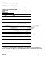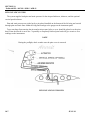
1
ZODIAC 601XL / 601XLi / 650LS / 650LSi
SLSA
CONTINENTAL 0-200 100 H.P.
PILOT OPERATING HANDBOOK
REGISTRATION:
SERIAL NUMBER:
©AMD
Original date of issue: November 2009
Revision 2 March 2010
PILOT OPERATING HANDBOOK
Model: Zodiac 601XL / 601XLi / 650LS / 650LSi
Serial No:
Registration: N
This manual is for the Zodiac 601XL / 601XLi / 650LS / 650LSi. Since the aircraft are very similar, this
POH merges the 601XL / 601XLi and 650LS / 650LSi together. It is important that all 601XLi / 650LS /
650LSi owners update to this new manual as there are important updates for all models. KCAS are
marked in this manual as per the LSA rule requirements. KIAS numbers must to be added beside each
KCAS number. Tables on page 5.4 must be completed for KIAS. From verification of KISA, see
AIRSPEED IN-FLIGHT ACCURACY Appendix 1 page 5 in the Service Manual.
THERE ARE INHERENT RISKS IN THE PARTICIPATION IN RECREATIONAL AVIATION
AIRCRAFT. OPERATORS AND PASSENGERS OF RECREATIONAL AIRCRAFT, BY
PARTICIPATION, ACCEPT THE RISK INHERENT IN SUCH PARTICIPATION ON WHICH THE
ORDINARY PRUDENT PERSON IS OR SHOULD BE AWARE. PILOTS AND PASSENGERS
HAVE A DUTY TO EXERCISE GOOD JUDGMENT AND ACT IN A RESPONSIBLE MANNER
WHILE USING THE AIRCRAFT AND TO OBEY ALL ORAL OR WRITTEN WARNINGS, OR
BOTH, PRIOR TO OR DURING USE OF THE AIRCRAFT, OR BOTH.
THIS AIRCRAFT WAS MANUFACTURED IN ACCORDANCE WITH LIGHT SPORT AIRCRAFT
AIRWORTHINESS STANDARDS AND DOES NOT CONFORM TO STANDARD CATEGORY
AIRWORTHINESS REQUIREMENTS
THIS MANUAL UPDATE IS BASED ON SAFETY ALERT OF NOVEMBER 2009. Airframe
upgrades must be completed if this POH is to be used with gross weight of 1,320 and VNE of 140
Knots.
Original date of issue: November 2009
This airplane is to be operated in compliance with the information and limitations contained herein.
0-1
Revision 2 March 2010
SECTION 0
Zodiac 601XL / 601XLi / 650LS / 650LSi
PILOT OPERATING HANDBOOK
List of Effective Pages
Section
Page
Date
0-1
0-2
0-3
0-4
Nov. 09
Nov. 09
Nov. 09
July 09
1-1
July 09
2-1
2-2
2-3
2-4
2-5
2-6
2-7
Nov. 09
July 09
July 09
July 09
July 09
July 09
March 10
3-1
March 10
4-1
4-2
4-3
4-4
4-5
4-6
4-7
4-8
July 09
July 09
July 09
July 09
July 09
July 09
July 09
Nov. 09
5-1
5-2
5-3
5-4
July 09
July 09
Nov. 09
Nov. 09
0-0
Section
Date
6-1
6-2
6-3
6-4
6-5
6-6
6-7
6-8
6-9
July 09
July 09
July 09
July 09
July 09
July 09
July 09
July 09
July 09
Section
6-0
1-0
2-0
7-0
3-0
4-0
5-0
0-2
Page
Page
Date
8-8
8-9
8-10
8-11
8-12
Nov. 09
July 09
July 09
July 09
July 09
9-1
9-2
9-3
9-4
July 09
Nov. 09
July 09
Nov. 09
10-1
10-2
10-3
10-4
10-5
10-6
10-7
10-8
July 09
July 09
July 09
July 09
July 09
July 09
July 09
July 09
11-1
11-2
11-3
July 09
July 09
Nov. 09
12-1
July 09
9-0
10-0
7-1
7-2
7-3
7-4
7-5
7-5A
7-6
7-7
7-8
7-9
7-10
7-11
7-12
7-13
7-14
7-15
7-16
Nov. 09
July 09
July 09
July 09
July 09
July 09
July 09
July 09
July 09
July 09
July 09
July 09
July 09
July 09
July 09
July 09
July 09
8-1
8-2
8-3
8-4
8-5
8-6
8-7
July 09
Nov. 09
Nov. 09
July 09
July 09
July 09
July 09
11-0
12-0
8-0
Revision 2 March 2010
SECTION 0
Zodiac 601XL / 601XLi / 650LS / 650LSi
REVISIONS
PILOT OPERATING HANDBOOK
UPDATE LOG
REV. NO.
DATE ISSUED
DATE
INCORPORATED
INSERTED
BY
0
JULY 08 09
JULY 08 09
AMD
1
November 2009
November 2009
2
March 2010
March 2009
Note: page 0-2 must be replaced for each new update.
Copyright AMD
The data and information contained in the document is the property of AMD. This document may not be
reproduced or transmitted to a third party, in any form or by any means. Any unauthorized copy, distribution is
illegal as per international agreements relating to property rights.
Revision 2 March 2010
0-3
TABLE OF CONTENTS
0-4
SECTION 0
REVISIONS
SECTION 1
GENERAL
SECTION 2
AIRPLANE AND SYSTEMS DESCRIPTION
SECTION 3
OPERATING LIMITATIONS
SECTION 4
WEIGHT AND BALANCE INFORMATION
SECTION 5
PERFORMANCE
SECTION 6
EMERGENCY PROCEDURES
SECTION 7
NORMAL PROCEDURES
SECTION 8
AIRCRAFT HANDLING AND MAINTENANCE
SECTION 9
REQUIRED PLACARDS AND MARKINGS
SECTION 10
SUPPLEMENTARY INFORMATION
SECTION 11
OPTIONS
SECTION 12
FAMILIARIZATION FLIGHT PROCEDURES
JULY 09
SECTION 1
GENERAL
WARNING
THE OWNER AND OPERATOR MUST UNDERSTAND THAT DUE
TO INHERENT RISK INVOLVED
IN FLYING AN AIRCRAFT, NO WARRANTY IS MADE OR
IMPLIED, OF ANY KIND, AGAINST ACCIDENTS, BODILY
INJURY OR DEATH OTHER THAN THOSE, WHICH CANNOT BY
LAW BE EXCLUDED.
THE SAFE OPERATION OF THIS AIRCRAFT RESTS WITH YOU,
THE PILOT. WE BELIEVE THAT IN ORDER TO FLY SAFELY
YOU MUST MATURELY PRACTICE AIRMANSHIP.
OPERATIONS OUTSIDE THE RECOMMENDED FLIGHT
ENVELOPE SUCH AS AEROBATIC MANEUVERS OR ERRATIC
PILOT TECHNIQUE MAY ULTIMATELY PRODUCE EQUIPMENT
FAILURE. YOU ARE REFERRED TO THE OPERATING
LIMITATIONS IN THIS MANUAL.
LIKE ANY AIRCRAFT, SAFETY DEPENDS ON A COMBINATION
OF CAREFUL MAINTENANCE
AND YOU’RE ABILITY TO FLY INTELLIGENTLY AND
CONSERVATIVELY. WE HOPE THAT YOUR AIRCRAFT WILL
PROVIDE YOU WITH MANY HOURS OF SAFE AND
ENJOYABLE FLYING.
JULY 09
1-0
SECTION 1
Zodiac 601XL / 601XLi / 650LS / 650LSi
SECTION 1
GENERAL
INTRODUCTION
This Pilot Operating Handbook (POH) is designed for maximum utilization as an operating guide for the
pilot. It includes the material required by the regulations to be furnished to the pilot. It also contains
supplemental data supplied by the airplane manufacturer.
This Pilot Operating Handbook is not designed as a substitute for adequate and competent flight instruction,
knowledge of current airworthiness directives, applicable air regulations or advisory circulars. It is not intended
to be a guide for basic flight instruction or a training manual and should not be used for operational purposes
unless kept in a current status.
Assurance that the airplane is in an air worthy condition is the responsibility of the owner. The pilot
in command is responsible for determining that the airplane is safe for flight. The pilot is also responsible for
remaining within the operating limitations as outlined by instrument markings, placards, and this Pilot
Operating Handbook.
Although the arrangement of this Pilot Operating Handbook is intended to maximize its in-flight capabilities,
it should not be used solely as an occasional operating reference. The pilot should study the entire Pilot
Operating Handbook to become familiar with the limitations, performance, normal and emergency procedures
and operational handling characteristics of the airplane before flight.
The Pilot Operating Handbook has been divided into numbered (Arabic) sections. The limitations and
emergency procedures have been placed ahead of the normal procedures, performance and other sections to
provide easier access to information that may be required in flight. The "Emergency Procedures" Section is
quickly available, to present an instant reference. Provisions for expansion and/or updates to this Pilot
Operating Handbook (POH) have been made.
Before flying the aircraft, read and familiarize yourself with this POH, the Engine Operators Manual and
Maintenance Manual.
CERTIFICATION BASIS
FAA Special Light Sport Aircraft (SLSA) category
WARNINGS, CAUTIONS AND NOTES
The following definitions apply to warnings, cautions and notes used in the Pilot Operating Handbook.
WARNING: means that the non-observation of the corresponding procedure leads to an immediate
degradation of flight safety which could result in loss of life or destruction of
equipment.
CAUTION: means that the non-observation of the corresponding procedure leads to a degradation
of flight safety resulting in damage to the equipment.
NOTE:
draws the attention to any item that is important or unusual.
1-1
JULY 09
SECTION 2
AIRPLANE AND SYSTEMS DESCRIPTION
JULY 09
2-0
SECTION 2
Zodiac 601XL / 601XLi / 650LS / 650LSi
SPECIFICATIONS
ZODIAC 601XL / 601XLi / 650LS / 650LSi
WING SPAN . . . . . . . . . . . . . . . . . . . . . . . . . . . . . . . . . . . . . . . .27 FT.
WING AREA . . . . . . . . . . . . . . . . . . . . . . . . . . . . . . . . . . . 134 SQ. FT.
LENGTH . . . . . . . . . . . . . . . . . . . . . . . . . . . . . . . . . . . . . . . . . . . 20 FT.
ENGINE . . . . . . . . . . . . . . . . . . . . . . . . . . . . . . . . . . . . . . . . . . 100BHP
PROPELLER (Fixed Pitch) . . . . . . . .. . . . . . . . . . . . . . . . . . . . 58 IN.
WING ASPECT RATIO . . . . . . . . . . . . . . . . . . . . . . . . . . . . . . . . . . 5.4
GROSS WEIGHT . . . . . . . . . . . . . . . . . . . . . . . . . . . . . . . . . . 1320 lbs
Nov. 09
2-1
SECTION 2
Zodiac 601XL / 601XLi / 650LS / 650LSi
ENGINE
- 4 Cylinders Horizontally Opposed - Air Cooled
Engine Manufacturer
Engine Model Number
Rated Horsepower
RPM Rating, standard atmosphere Max.
continuous
Recommended cruising RPM
Compression Ratio
FUEL - Standard
Fuel Capacity,
Usable Fuel (U.S. gal) (total)
Minimum fuel grade. See engine manual
left + right tanks
left + right tanks
Teledyne Continental
0-200-A & D
100
2750
2500
7.0:1 & 8.1:1
30 U.S. gal.
28 U.S. gal
80/87
OIL
Oil sump. capacity 0-200-A
Oil sump. capacity 0-200-D
Oil grade - Below 40° F
- Above 40° F.
6 Quarts
5 Quarts
SAE 20
SAE 40
Note: See engine Operators Manual on above for more details.
PROPELLER - Fixed Pitch
Propeller Manufacturer
Model
Number of Blades
Propeller Diameter (inches)
Sensenich
W68ZK-56-58
2
68-70
OPERATING WEIGHTS
Maximum Takeoff Weight (lbs)
Maximum Landing Weight (lbs)
Maximum Weights in Baggage Compartment
behind seats.
See weight and balance
Nov. 09
1320 lbs
1320 lbs
40 lbs
2-2
SECTION 2
Zodiac 601XL / 601XLi / 650LS / 650LSi
SYMBOLS, ABBREVIATIONS AND TERMINOLOGY
The following definitions are of symbols, abbreviations and terminology used throughout the handbook and
those which may be of added operational significance to the pilot.
• General Airspeed Terminology and Symbols
BHP
JULY 09
Brake horsepower (= rated horsepower of the engine)
CAS
Calibrated Airspeed means the indicated speed of an aircraft, corrected
for position and instrument error. Calibrated airspeed is equal to true
airspeed in standard atmosphere at sea level.
GPH
Fuel consumption in Gallons (U.S.) per Hour.
KCAS
Calibrated Airspeed expressed in "Knots".
C.G.
Centre of Gravity.
IAS
Indicated Airspeed is the speed of an aircraft as shown on the airspeed
indicator.
KIAS
Indicated Airspeed expressed in "Knots".
L
Left
R
Right
RPM
Revolutions per minute.
S.L.
Sea Level
TAS
True Airspeed is the airspeed of an airplane relative to undisturbed air
which is the CAS corrected for altitude and temperature.
V
Speed.
VA
Maneuvering Speed is the maximum speed at which the controls may be
fully (and smoothly) deflected in calm air as long as +4/-2 g is not
exceeded. Do not make full or abrupt control movements above this
speed.
VFE
Maximum Flap Extended Speed is the highest speed permissible with
wing flaps partially or fully extended.
2-3
SECTION 2
Zodiac 601XL / 601XLi / 650LS / 650LSi
General Airspeed Terminology and Symbols (continued)
2-4
VNE
Never Exceed Speed is the speed limit that may not be exceeded at any
time.
VC
Design Cruising Speed is the speed that should not be exceeded except in
smooth air and only with caution.
VS
Stalling Speed or the minimum steady flight speed at which the airplane
is controllable (flaps up).
VSO
Stalling Speed at which the airplane is controllable in the landing
configuration.
VX
Best Angle-of-Climb Speed is the air speed which delivers the greatest
gain of altitude in the shortest horizontal distance.
VY
Best Rate-of-Climb Speed is the air speed which delivers the greatest
gain in altitude in the shortest time.
JULY 09
SECTION 2
Zodiac 601XL / 601XLi / 650LS / 650LSi
• Meteorological Terminology
ISA
International Standard Atmosphere in which:
The air is a dry perfect gas;
The temperature at sea level is 15o Celsius (59o Fahrenheit);
The pressure at sea level is 29.92 inches hg. (1013 mb);
The temperature gradient from sea level up, is: - 1.98o C per
1000 ft or - 6.5o C per 1000 meter, or -3.57o F per 1000 ft.
OAT
Outside Air Temperature is the free air static temperature, obtained
either from inflight temperature indications or ground
meteorological sources, adjusted for instrument error.
Indicated
Pressure Altitude
The number actually read from an altimeter when the barometric
subscale has been set to 29.92 inches of mercury (1013 millibars).
Pressure Altitude
Altitude measured from standard sea-level pressure (29.92 in. Hg)
by a pressure or barometric altimeter. It is the indicated pressure
altitude corrected for position and instrument error. In this Pilot
Operating Handbook, altimeter instrument errors are assumed to be
zero.
Station Pressure
Actual atmospheric pressure at field elevation.
Wind
The wind velocities recorded as variables on the charts of this Pilot
Operating Handbook are to be understood as the headwind or
tailwind components of the reported winds.
•
Units
Speed:
Kts (Knots) = 1.15 mph (miles per hour)
Pressure: PSI = Pounds per Square Inch
in Hg = inches of Mercury
mb = millibar
Distances: in. = inches = 25.4 millimeters
ft = foot (feet) = .305 meters
Weights:
JULY 09
Kg = kilograms = 2.2 lbs = 2.2 pounds
2-5
SECTION 2
Zodiac 601XL / 601XLi / 650LS / 650LSi
• Power Terminology
Takeoff Power
Maximum power permissible for takeoff.
Maximum Continuous
Power
Maximum power permissible continuously during flight.
Maximum Climb Power
Maximum power permissible during climb.
Maximum Cruise Power
Maximum power permissible during cruise.
• Engine Instruments
CHT Gauge
Cylinder Head Temp.
• Airplane Performance and Flight Planning Terminology
2-6
Climb Gradient
The demonstrated ratio of the change in height during a
portion of a climb, to the horizontal distance traversed in
the same time interval.
Demonstrated Crosswind
Velocity
The demonstrated crosswind velocity is the velocity of the
90 deg. crosswind component for which adequate control
of the airplane during takeoff and landing was actually
demonstrated.
JULY 09
SECTION 2
Zodiac 601XL / 601XLi / 650LS / 650LSi
• Weight and Balance Terminology
Reference Datum
An imaginary vertical plane from which all horizontal
distances are measured for balance purposes: wing leading
edge at rib #3
Station
A location along the airplane fuselage centerline given in
terms of distance from the Reference Datum.
Position or Arm
The horizontal distance from the Reference datum to the
center of gravity (C.G.) of an item parallel to fuselage
centerline.
Moment
The product of the weight of an item multiplied by its arm.
(Moment divided by a constant is used to simplify balance
calculations by reducing the number of digits.)
Center of Gravity
(C.G.)
The point at which an airplane would balance if suspended.
Its distance from the reference datum is found by dividing
the total moment by the total weight of the airplane.
C.G. Arm
The arm obtained by adding the airplane's individual
moments and dividing the sum by the total weight.
C.G. Limits
The extreme center of gravity locations within which the
airplane must be operated at a given weight.
Usable Fuel
Fuel available for flight planning.
Unusable Fuel
Fuel remaining after a runout test has been completed in
accordance with the design standards.
Standard Empty Weight
Weight of a standard airplane including unusable fuel, full
operating fluids and full oil.
Empty Weight
Standard empty weight plus optional equipment.
Payload
Weight of occupants, fuel and baggage.
Useful Load
Difference between takeoff weight, and empty weight.
Maximum Takeoff
Weight
Maximum approved weight.
MZFW
&
MTOW
The Maximum Zero Fuel Weight (MZFW) case is the
condition where two occupants (190 lbs each, according the
ASTM standard) are added to the empty weight of the
airplane. Then sufficient fuel is added to the wing tanks to
reach Maximum Take Off Weight (MTOW).
Revision 2 March 2010
2-7
SECTION 3
OPERATING LIMITATIONS
JULY 09
3-0
SECTION 3
Zodiac 601XL / 601XLi / 650LS / 650LSi
SECTION 3
OPERATING LIMITATIONS
GENERAL
This section includes operating limitations and instrument markings necessary for safe operation of the
airplane, its engine, standard systems and standard equipment.
AIRSPEED LIMITATIONS
SPEED
KCAS
(Knots)
VS Stall Speed at Maximum takeoff weight
– FLAPS UP
43
VSO Stall Speed at Maximum takeoff
weight – FLAPS DOWN
38
VFE Maximum Flap Extended Speed
70
VA Design Maneuvering Speed
KIAS
(Knots)
Do not exceed this speed with flaps extended.
Do not make full or abrupt control movements
above this speed.
82
VNE Never Exceed Speed
140
VC Design Cruising Speed
108
REMARKS
Do not exceed this speed in any operation.
Do not exceed this speed except in smooth air
and then only with caution.
CROSSWIND AND WIND LIMITATION: 20 Kts
SERVICE CEILING: 15,000 feet
LOAD FACTORS (LIMIT):
Flap up: Positive + 4 g
Negative - 2 g
(Ultimate is 1.5 times limit)
Flap extended: Positive + 2 g
Negative - 0 g
PROHIBITED MANEUVERS:
Intentional spins prohibited.
Aerobatics prohibited.
WARNING
Exceeding the maximum load factors will lead to an
overstressing of the airplane.
TYPES OF OPERATIONS
The airplane is approved for the following operations when equipped in accordance with the prevailing
regulations.
Day V.F.R. (see POH supplements for other operations)
Flight in known or forecast icing conditions is prohibited.
3-1
Revision 2 March 2010
SECTION 4
WEIGHT AND BALANCE INFORMATION
4.0
JULY 09
SECTION 4
Zodiac 601XL / 601XLi / 650LS / 650LSi
SECTION 4
WEIGHT AND BALANCE
4.1 GENERAL
In order to achieve the performance and flying characteristics which are designed into the airplane, it must be
flown with the weight and center of gravity (C.G.) position within the approved operating range (envelope).
Although the airplane offers flexibility of loading, the pilot must ensure that the airplane is loaded within the
envelope before attempting to take off.
Mis-loading carries consequences for any aircraft. An overloaded airplane will not take off, climb or cruise
properly. The heavier the airplane is loaded, the less climb performance it will have.
Center of gravity is a determining factor in flight characteristics. If the C.G. is too far forward in any
airplane, it will be difficult to rotate for takeoff or landing and the nose gear overstressed at landings! If the
C.G. is aft of the approved limit, the airplane may rotate prematurely on takeoff or tend to pitch up or down; the
aircraft will be unstable in pitch. This can lead to inadvertent stalls and even spins; stall and spin recovery may
be impossible in an improperly loaded airplane.
A properly loaded airplane, however, will perform as intended. Before the airplane is delivered, it is
weighed, and the corresponding empty weight and C.G. location is computed (the empty weight consists of the
standard empty weight of the airplane plus the optional equipment). Using the empty weight and C.G. location,
pilots can easily determine the weight and C.G. position for the loaded airplane by computing the total weight
and moment and then determining whether they are within the approved envelope.
The empty weight and C.G. location are recorded in the Weight and Balance Record Form. The current
values should always be used. Whenever new equipment is added or any modification work is done, a new
empty weight and C.G. position should be determined and recorded. The owner must make sure that this is
done.
To determine a new empty-weight C of G, the airplane must first be weighed and then the new C of G
position must be calculated.
To determine the C of G for the loaded airplane, loaded weight and balance calculations must be performed
before flight.
4-1
JULY 09
SECTION 4
Zodiac 601XL / 601XLi / 650LS / 650LSi
4.2 INSTALLED EQUIPMENT LIST
Maintain an up to date list of installed equipment.
Aircraft Model: _________________.
Serial #
.
Registration #
.
Description
Weight lbs
C.G. Position
inches
Date
Entered by
Note: New manufactured aircraft comes with a detailed list of installed equipment. Make sure you have this list.
JULY 09
4-2
SECTION 4
Zodiac 601XL / 601XLi / 650LS / 650LSi
4-3
July 09
SECTION 4
Zodiac 601XL / 601XLi / 650LS / 650LSi
WEIGHT AND BALANCE RECORD
Maintain an up to date weight and balance record using the present form.
WEIGHT AND BALANCE RECORD
Aircraft Model: _____________.
Serial #
.
Registration #
.
Empty Weight
lbs
C.G. Position
inches
Date
Entered by
The form is to be used to present the current status of the airplane empty weight and a complete history of
previous modifications. Any change to the permanently installed equipment or modification that affects weight
or moment must be entered in the Weight and Balance Record.
See optional equipment list page or any other item.
JULY 09
4-4
SECTION 4
Zodiac 601XL / 601XLi / 650LS / 650LSi
4.3 AIRPLANE WEIGHING PROCEDURE
The removal or addition of equipment or airplane modifications may affect basic empty weight and center of
gravity. The following is a weighing procedure to determine this empty weight and center of gravity location:
Preparation
(1) Be certain that all items checked in the airplane equipment list are installed in the proper
location in the airplane.
(2) Remove dirt, grease, moisture, foreign items such as rags and tools from the
airplane before weighing.
(3) Defuel airplane: Open the fuel drain until all fuel is drained.
CAUTION
Whenever the fuel system is completely drained and fuel is
replenished, it will be necessary to run the engine for a minimum
of three minutes above idle (on each tank) to insure no air remains
in the fuel supply lines.
(4) Fill with oil to full capacity.
(5) Flaps fully up and all control surfaces in the neutral position. Canopy and access panels closed.
(6) Place the airplane on weighing scales inside a closed building to prevent errors in scale
readings due to wind, and block the main gear.
Leveling
The horizontal reference is the upper fuselage longeron (at canopy sill).
Level airplane, by raising or lowering the nose wheel (lower by removing air from nose wheel tire),
to center bubble on level placed on doorsill.
After Weighing the Airplane
Re-inflate the nose wheel tire if required (28-30 PSI)
Use table of weight & Balance report and fill in table weight & Balance record.
JULY 09
4-5
SECTION 4
Zodiac 601XL / 601XLi / 650LS / 650LSi
Weight and Balance Calculations for Flight
Before each flight, the weight and balance of the loaded airplane should be calculated as follows and
checked to fit inside the approved limits.
Following tables may be used:
1) Obtain the Empty weight and C.G. position
Use the latest figures from the Weight and Balance record.
2) Use the applicable values shown in following table listing the fuel in each wing tank.
Fuel in each wing tank
Gauge
Quantity Weight
each tank
US gal
lbs
1
15
90
1/2
7
42
0
0
-----
Position
inches
7”
7”
-----
Moment
lbs.inches
630
295
-----
Note: 1 U.S. gal fuel = 6 lbs.
3) Use the applicable values shown in following table for the occupants.
Weight
lbs
100
150
200
250
300
350
400
Position
*
inches
28
28
28
28
28
28
28
Moment*
lbs. inches
2,800
4,200
5.600
7,000
8,400
9,800
11,200
* Note: The exact position of the occupants depends on their geometry (!) and the seat adjustment (use of
cushions).
Above table gives only an average; more accurate results will be obtained by using actual figures.
Note: Measure the Position with tape measure from the DATUM line (front of wing leading edge) and enter
into tables for more accurate results.
JULY 09
4-6
SECTION 4
Zodiac 601XL / 601XLi / 650LS / 650LSi
4) Use the applicable values shown in the following table for fuselage baggage.
FUSELAGE BAGGAGE (behind seat – top) MAXIMUM 40 LBS.
Weight
Position*
Moment*
lbs
inches
lbs.inches
10
63
630
20
63
1,260
30
63
1,890
40
63
2,520
BAGGAGE WING LOCKER LEFT
Weight
Position*
Moment*
lbs
inches
lbs.inches
10
26
260
20
26
520
30
26
780
40
26
1,040
MAXIMUM 40 LBS.
BAGGAGE WING LOCKER RIGHT
Moment*
Weight
Position*
lbs
inches
lbs.inches
10
26
260
20
26
520
30
26
780
40
26
1,040
MAXIMUM 40 LBS.
5) Enter all the applicable values obtained from weight & balance report and above tables into the appropriate
blocks below and perform the necessary calculations.
Weight
kg or lbs
Position
inches
Moment
lbs.inches
1) Empty
2) Fuel
3) Occupant
4) Baggage Fuselage
45 Baggage Wings
Total (add the columns)
W=
M=
Loaded Aircraft weight is W = ______(lbs)
Loaded C.G. position is x = M/W =
______
=
(x in inches)
Check that both W and x fall within the limits.
Note: You may also want to repeat the above calculation corresponding to the aircraft at the end of the
trip, which means with the fuel level as expected at destination.
Note: Measure the Position with tape measure from the DATUM line (front of wing leading edge)
and enter into tables for more accurate results.
JULY 09
4-7
SECTION 4
Zodiac 601XL / 601XLi / 650LS / 650LSi
WEIGHT & BALANCE CHART
Nov. 09
4-8
Aircraft Weight
Aircraft CG
Moment
Max Gross Weight
Useful Load
1,320
Lbs.
Inches
Moment
Lbs.
Lbs.
CG Limits: 10.8 - 18 inches
REG. NO.
MODEL
Serial No.
ZODIAC
Weight
Arm
Moments
Lbs.
Inches
Lbs. / Inch
Nose Wheel Weight
-20
RT Wheel Weight
24.75
LT Wheel Weight
24.75
Pilot
28
Co-Pilot
26
Fuel AvGas 30 Gals. @ 6 lbs. 180 lbs
7
Baggage Behind
0
63
Wing Lockers (optional)
0
26
Weight & CG
For aircraft loading, see instructions in Weight & Balance Section of Aircraft Flight Manual.
By: Garry Webster
Nov. 09
W&B Supplement
SECTION 5
PERFORMANCE
JULY 09
5-0
SECTION 5
Zodiac 601XL / 601XLi / 650LS / 650LSi
SECTION 5
PERFORMANCE
GENERAL
All of the required performance information applicable to this aircraft is provided by this section.
JULY 09
5-1
SECTION 5
Zodiac 601XL / 601XLi / 650LS / 650LSi
TAKE OFF ROLL:
From hard surface, full power at brake release, flaps up
S.L. = 0
3,000 feet
6,000 feet
Altitude
Std. -30 deg. F.
450
600
800
Std.
490
660
880
Std +30 deg. F.
550
740
970
Temperature
Above values are in feet
On grass, increase above values by 20% approximately.
Above values decrease by approximately 30% for 10 kts headwind and 45 % for 20 kts headwind.
TAKE OFF ROLL + CLIMB TO CLEAR 50 FT. OBSTICLE AT 60 KCAS:
From hard surface, full power at brake release, flaps up
S.L. = 0
3,000 feet
6,000 feet
Altitude
Std. -30 deg. F.
740
900
1210
Std.
820
1000
1350
Std +30 deg. F.
900
1100
1480
Temperature
Above values are in feet
On grass, increase above values by 20% approximately.
Above values decrease by approximately 25% for 10 kts headwind and 40% for 20 kts headwind.
LANDING ROLL:
S.L. = 0
3,000 feet
6,000 feet
Altitude
Std. -30 deg. F.
450
510
570
Std.
490
560
630
Std +30 deg. F.
550
620
700
Temperature
Above values are in feet
JULY 09
5-2
SECTION 5
Zodiac 601XL / 601XLi / 650LS / 650LSi
LANDING DISTANCE:
Landing distance from 50 ft. height, flaps down, throttle idle, approach speed = 60 KCAS
S.L. = 0
3,000 feet
6,000 feet
Altitude
Std. -30 deg. F.
670
740
800
Std.
750
820
900
Std +30 deg. F.
820
900
990
Temperature
Std.
900
750
600
450
Std +30 deg. F.
860
710
560
420
Temperature
RATE OF CLIMB:
1,320 lbs, flaps up and full throttle at Vy = 60 KCAS
S.L. = 0
3,000 feet
6,000 feet
9,000 feet
Altitude
Std. -30 deg. F.
930
780
630
480
CRUISE SPEEDS & RPM
Cruise speeds and RMP in standard atmosphere and 75% power (above 7,000 ft. the power is less)
S.L. = 0
3,000 feet
6,000 feet
9,000 feet (less than 75%)
Altitude
RPM
2500
2600
2700
2750
IAS - kts
CAS - kts
103
108
112
102
Range - MPH
410
440
450
420
At 75% power, the fuel consumption is about 5 gal/hr.
With 2 x 14 = 28 gal. fuel tanks full, the endurance is about 5.2 hours (unusable fuel is 1 gal. each tank).
Note: Reducing the power will reduce the speed and fuel consumption and slightly increase the range.
BEST ANGLE OF CLIMB:
Best angle of climb Vx is ____ KIAS, (58 KCAS)
Flaps up, full power at 1,320 lbs.
Nov. 09
5-3
SECTION 5
Zodiac 601XL / 601XLi / 650LS / 650LSi
CROSSWIND:
The demonstrated takeoff and landing crosswind component is 20 kts.
SERVICE CEILING:
Where rate of climb is 100 FPM in standard atmosphere: 15,000 feet.
AIRSPEED CALIBRATION KTS – FLAPS UP
KIAS
KCAS
35
50
70
90
110
121
AIRSPEED CALIBRATION KTS – FLAPS DOWN
KIAS
KCAS
30
40
50
60
Above calibration is specific to this aircraft.
NOTE:
KCAS
KIAS
Calibrated Airspeed means the indicated speed of an aircraft, corrected
for position and instrument error. Calibrated airspeed is equal to true
airspeed in standard atmosphere at sea level. Calibrated Airspeed
expressed in "Knots".
Indicated Airspeed is the speed of an aircraft as shown on the airspeed
indicator. Indicated Airspeed expressed in "Knots".
NOTE: If KIAS does not seem correct, see Maintenance Manual Appendix 1, AIRSPEED IN-FLIGHT
ACCURACY
STALL SPEEDS AT 1,320 lbs. (Max. take off weight)
Flaps up Vs = ____ KIAS, 43 KCAS
Flaps down Vso = ____ KIAS, 38 KCAS
NOV 09
5-4
SECTION 6
EMERGENCY PROCEDURES
JULY 09
6-0
SECTION 6
Zodiac 601XL / 601XLi / 650LS / 650LSi
SECTION 6
EMERGENCY PROCEDURES
GENERAL
The recommended procedures for coping with various types of emergencies and critical situations are
provided by this section.
The first portion of this section consists of an abbreviated emergency check list which supplies an action
sequence for critical situations with little emphasis on the operation of the systems.
The remainder of the section is devoted to amplified emergency procedures containing additional information
to provide the pilot with a more complete understanding of the procedures.
These procedures are suggested as the best course of action for coping with the particular condition
described, but are not a substitute for sound judgment and common sense. Pilots should familiarize themselves
with the procedures given in this section and be prepared to take appropriate action should
an emergency arise. See Engine Operators Manual for more information.
JULY 09
6-1
SECTION 6
Zodiac 601XL / 601XLi / 650LS / 650LSi
EMERGENCY PROCEDURES CHECK LIST
ENGINE FIRE DURING START
ENGINE FAILURE IN FLIGHT
(Restart Procedure)
Starter . . . . . . . . . . . . . . . . . . . continue cranking
( If engine starts)
Power . . . . . . . . . . .1700 RPM momentarily
Engine . . . SHUTDOWN and inspect for damage
(If engine fails to start)
Ignition . . . . . . . . . . . . . . . . . . . . . . . . . . . . OFF
Master Switch . . . . . . . . . . . . . . . . . . . . . . OFF
Mixture . . . . . . . . . . . . . . . . . . .IDLE CUT OFF
Fuel . . . . . . . . . . . . . . . . . . . . . . . . . . . . . . OFF
(abandon aircraft and fight fire)
Airspeed . . . . . . . . . . . . .____ KIAS (60 KCAS)
Fuel Selector . . . . . . . . . . . . . . . . . . . . . . . . . ON
Aux Fuel Pump . . . . . . . . . . . . . . . . . . . . . . . ON
Mixture . . . . . . . . . . . . . . . . . . . . . . . . . . . RICH
Mag. Switch . . . . . . . . . . . . . . . . . . . . . . . BOTH
Carburetor Heat . . . . . . . . . . . . . . . . . . . . . . ON
Gauges . . . . . . . . Check for source of power loss
See engine manual
ENGINE FAILURE DURING TAKEOFF
POWER OFF LANDING
Throttle . . . . . . . . . . . . . . . . . . . . . . . . . . . IDLE
Brakes . . . . . . . . . . . . . . . . . . . . . . . . . . APPLY
Wing Flaps . . . . . . . . . . . . . . . . . . . . . . . . . . UP
Mixture . . . . . . . . . . . . . . . . . . IDLE CUT-OFF
Ignition Switch . . . . . . . . . . . . . . . . . . . . . . .OFF
Master Switch . . . . . . . . . . . . . . . . . . . . . . . OFF
Touchdowns should normally be made at lowest
possible airspeed with full flaps.
ENGINE FAILURE AFTER TAKEOFF
Airspeed . . . . . . . . . . . . .____ KIAS (60 KCAS)
Mixture . . . . . . . . . . . . . . . . . . IDLE CUT-OFF
Fuel Selector . . . . . . . . . . . . . . . . . . . . . . . OFF
Ignition Switch . . . . . . . . . . . . . . . . . . . . . . OFF
Wing Flaps. . . . . . . . . . . . . . . . . AS REQUIRED
Master Switch . . . . . . . . . . . . . . . . . . . . . . OFF
When committed to landing:
Ignition . . . . . . . . . . . . . . . . . . . . . . . . . . . OFF
Master Switch . . . . . . . . . . . . . . . . . . . . . . . OFF
Fuel selector . . . . . . . . . . . . . . . . . . . . . .. . .OFF
Mixture . . . . . . . . . . . . . . . . . .IDLE CUT OFF
Seat belt and harness . . . . . . . . . . . . . . . Secure
CANOPY OPENING IN FLIGHT
Keep your hands on the controls
Lower your speed to approximately 60 knots,
keep flying the aircraft
Land as soon as practicable.
WARNING: Do not try to close the canopy in
flight: Fly the aircraft!
JULY 09
6-2
SECTION 6
Zodiac 601XL / 601XLi / 650LS / 650LSi
PRECAUTIONARY LANDING WITH
ENGINE POWER
Seats, Seat Belts, Shoulder Harnesses ..SECURE
Airspeed . . ____ KIAS (60 KCAS) (flaps UP)
____ KIAS (60 KCAS) (flaps down)
Mixture . . . . . . . . . . . . . . . . . . . . . . . . . . RICH
Fuel Selector. . . . . . . . . . . . . . . . . . . . . . . . . .ON
Ignition Switch . . . . . . . . . . . . . . . . . . . . . .. .ON
Wing Flaps . . . . . . . . . . . . . . . . . . . as required
Master Switch . . . . . . . . . . . . . . . . . . . . . . . .ON
Touchdown . . . . . . . . . . . . . . . ..slightly tail low
Brakes . . . . . . . . . . . . . . . . . . . . . . . as required
FIRE IN FLIGHT
HIGH OIL TEMPERATURE
Land at nearest airport and investigate the
problem. Prepare for power off landing.
ALTERNATOR FAILURE
Verify failure
Reduce electrical load as much as possible.
Circuit breakers . . . . . . . . . . . . . . . . .check
Alt. switch. . . . . .OFF (for 1 second), then ON
If no input Alt field. . . . . . . . . . . . . . . . . . OFF
Reduce electrical load and land as soon as
practical.
SPIN RECOVERY
Source of fire . . . . . . . . . . . . . . . . . . . . . . .check
Electrical fire (smoke in cabin):
Master switch and Alt. Field. . . . . . . . . . . ..OFF
Vents . . . . . . . . . . . . . . . . . . . . . . . . . . . . OPEN
Cabin heat . . . . . . . . . . . . . . . . . . . . . . . . . . OFF
Fire Extinguisher . . . . . . . . . . .If and as required
Land as soon as practical.
Engine fire:
Cabin Heat . . . . . . . . . . . . . . . . . . . . . . . . . OFF
Fuel selector . . . . . . . . . . . . . . . . . . . . . . . ..OFF
Throttle . . . . . . . . . . . . . . . . . . . . . . . . CLOSED
Mixture . . . . . . . . . . . . . . . . . . IDLE CUT-OFF
Auxiliary fuel pump . . . . . . . . . . . . . . . . . . OFF
Proceed with POWER OFF LANDING procedure
LOSS OF OIL PRESSURE
Reduce power.
Prepare for power off landing, and land as soon
as practical.
LOSS OF FUEL PRESSURE
Auxiliary fuel pump . . . . . . . . . . . . . . . . . . .ON
Fuel selector . . . . . . . . . . . . . . . . . . check "ON"
Land at nearest airport and investigate problem.
JULY 09
Rudder . . . . . . . . . Full opposite to spin direction.
Ailerons . . . . . . . . Full opposite to spin direction.
Pitch . . . . . . . . . . . . . . . . . . . . . . . . Full forward.
When rotation stops, centralize rudder and ease
control back to gently recover from dive.
careful not to exceed the speed and g load limits.
If flaps were extended: retract them during
recovery. Observe flap limit speed, if flaps are
down.
ENGINE ROUGHNESS
Carburetor heat . . . . . . . . . . . . . . . . . . . . . . . ON
Mixture . . . . . . . . . . adjust for max. smoothness
Auxiliary fuel pump . . . . . . . . . . . . . . . . . . . ON
Fuel selector . . . . . . . . . . . . . . . . . . . check open
Engine gauges . . . . . . . . . . . . . . . . . . . . . . check
Magneto switch . . . . . . . . . . . . . . . . . . "BOTH"
If operation is satisfactory on either one, continue
on that magneto at reduced power and full
"RICH" mixture to first airport.
Prepare for power off landing.
Also seen Engine Operates Manual
6-3
SECTION 6
Zodiac 601XL / 601XLi / 650LS / 650LSi
ICING
Inadvertent Icing Encounter
Ensure Pitot heat (IFR option) is ON
Turn back or change altitude to obtain an outside
air temperature that is less conducive to icing.
Ammeter Indicates Discharge
NOTE
Radios . . . . . . . . . . . . . . . . . . . . . . . . . . . . .OFF
Alternator Circuit Breaker . . . . . . . CHECK ON
Master Switch . . . . . . . . . . . . . . . . . . . . . . OFF
Master Switch . . . . . . . . . . . . . . . . . . . . . . . .ON
Radios . . . . . . . . . . . . . . . . . . . . . . . . . . . . . .ON
Pull cabin heat control full out to obtain
maximum air temperature. IFR airframe has small If Ammeter Continues Indicating Discharge
windshield defroster when cabin heat is pulled.
Alternator . . . . . . . . . . . . . . . . . . . . . . . . . . OFF
Open the throttle to increase engine speed and
Nonessential Radio and Elect. Equipment OFF
minimize ice build-up on propeller blades.
Flight . . . . . . . . . Terminate as soon as possible
Apply carburetor heat as required. Lean the
ELECTRIC FLAP
mixture for maximum RPM, if carburetor heat is
used continuously.
Should the flaps become inoperative, the flight
may be continued safely provided following is
Plan a landing at the nearest airport. With an
kept in mind:
extremely rapid ice build-up, select a suitable "off
airport" landing site.
Flaps Down: Do not exceed ____ KIAS
(80 KCAS)
With ice accumulation on the wing leading edges, Caution: The rate of climb is reduced.
be prepared for significantly higher stall speed.
Monitor the engine oil temperature.
Leave wing flaps retracted. With a severe ice
Flaps Up: Approach at ____ KIAS (60 KCAS)
build-up on the horizontal tail, the change in wing Caution: Be prepared for a longer landing
wake airflow direction caused by wing flap
distance.
extension could result in a loss of elevator
effectiveness.
ELECTRIC TRIM
ELECTRICAL POWER SUPPLY SYSTEM
MALFUNCTIONS
Ammeter Shows Excessive Rate of Charge
(Full scale deflection)
Alternator . . . . . . . . . . . . . . . . . . . . . . . . . . OFF
Alternator Circuit Breaker . . . . . . . . . . . . . . OFF
Nonessential Electrical Equipment . . . . . . . .OFF
Flight . . . . . . . . . .Terminate as soon as possible
OR (option)
Master Switch . . . . . . . . . . . . . . . . .. . . . . . OFF
Nonessential Electrical Equipment . . . . . . . .OFF
Avionics master switch . . . . . . . . . . . . . . . . .ON
JULY 09
In case of complete electric failure (battery and
alternator) or trim runaway; the pilot will no
longer be able to neutralize the pitch control
forces. They may become quite heavy. Adjust
speed and power to minimize the forces on the
control and be prepared to have to exercise
unusually high pull or push especially during
landing.
LIGHTNING STRIKE
In case of a lightning strike, land at the nearest
airport to investigate the damage.
6-4
SECTION 6
Zodiac 601XL / 601XLi / 650LS / 650LSi
AMPLIFIED EMERGENCY PROCEDURES (GENERAL)
The following paragraphs are presented to supply additional information for the purpose of providing the
pilot with a more complete understanding of the recommended course of action and probable cause of an
emergency situation.
ENGINE FIRE DURING START
Engine fires during start are usually the result of over priming. The first attempt to extinguish the fire is to
try to start the engine and draw the excess fuel back into the induction system and blow the fire out.
If fire continues more than a few seconds, the engine should be shut down and the fire extinguished by the
best available means.
ENGINE POWER LOSS DURING TAKEOFF
The proper action to be taken if loss of power occurs during takeoff will depend on the circumstances of the
particular situation.
If sufficient runway remains to complete a normal landing, land straight ahead.
Any turn will increase the risk of stall or stall/spin, fatal at low altitude. Land as straight ahead as practical
and maintain a safe airspeed and make only a very shallow turn if necessary to avoid obstructions. Use of flaps
depends on the circumstances. Normally, flaps should be fully extended for touchdown.
If sufficient altitude has been gained to attempt a restart, maintain a safe airspeed and check the fuel selector,
check the Auxiliary fuel pump to ensure that it is "ON" and that the mixture is "RICH." The carburetor heat
should be "ON".
If power is not regained, proceed with the Power Off Landing procedure (refer to the emergency check list).
JULY 09
6-5
SECTION 6
Zodiac 601XL / 601XLi / 650LS / 650LSi
ENGINE POWER LOSS IN FLIGHT
Complete engine power loss is usually caused by fuel flow interruption and power will be restored shortly
after fuel flow is restored. If power loss occurs at a low altitude, the first step is to prepare for an emergency
landing.
If altitude permits, check the fuel and turn the Auxiliary fuel pump "ON." Move the mixture control to
"RICH" and the carburetor heat to "ON." Check the gauges for an indication of the cause of the power loss. If
no fuel pressure is indicated, check the tank selector position.
When power is restored move the carburetor heat and the Auxiliary fuel pump to "OFF".
If the preceding steps do not restore power, prepare for an emergency landing.
If time permits, turn the ignition switch to "L" then to "R" then back to "BOTH." Move the throttle and
mixture control levers to different settings. This may restore power if the problem is too rich or too lean a
mixture or if there is a partial fuel system restriction. Water in the fuel could take some time to be used up, and
allowing the engine to windmill may restore power. If power loss is due to water, fuel pressure indications will
be normal.
(If engine failure was caused by fuel exhaustion power will not be restored after switching fuel tanks until
the empty fuel lines are filled. This may require up to six seconds).
If power is not regained, proceed with the Power Off Landing procedure (refer to the emergency check list).
POWER OFF LANDING
If loss of power occurs at altitude, trim the aircraft for best gliding angle and look for a suitable field. If
measures taken to restore power are not effective, and if time permits, check your charts for airports in the
immediate vicinity; it may be possible to land at one if you have sufficient altitude. If possible, notify Air
Traffic Control or other facility by radio of your difficulty, position, and intentions.
When committed to a landing, flaps may be used as desired. Turn the fuel selector valve to "OFF" and pull
the mixture out. Shut "OFF" the master and ignition switches. The seat belts and shoulder harness should be
tightened. Touchdown should be normally made at the lowest possible airspeed.
JULY 09
6-6
SECTION 6
Zodiac 601XL / 601XLi / 650LS / 650LSi
FIRE IN FLIGHT
The presence of fire is noted through smoke, smell and heat in the cabin. It is essential that the source of the
fire be promptly identified through instrument readings, character of the smoke, or other indications since the
action to be taken differs somewhat in each case.
Check for the source of the fire first.
If an electrical fire is indicated (smoke in the cabin), the master switch should be turned "OFF." The cabin
vents should be opened and the cabin heat turned "OFF." If installed; use fire extinguisher as required. A
landing should be made as soon as possible.
If an engine fire is present, switch the fuel selector to "OFF" and close the throttle. The mixture should be
pulled out. Turn the Auxiliary fuel pump "OFF." In all cases, the cabin heat should be pushed "OFF." Once
final flap configuration is set, select master switch "OFF." Proceed with power off landing procedure.
LOSS OF OIL PRESSURE
Loss of oil pressure may be either partial or complete. A partial loss of oil pressure usually indicates a
malfunction in the oil pressure regulating system, and a landing should be made as soon as possible to
investigate the cause and prevent engine damage.
A complete loss of oil pressure indication may signify oil exhaustion or may be the result of a faulty gauge.
In either case, proceed toward the nearest airport at reduced power setting, and be prepared for a forced landing.
If the problem is not a pressure gauge malfunction, the engine may stop suddenly. Maintain altitude until such
time as a dead stick landing can be accomplished. Don't change power settings unnecessarily, as this may
hasten complete power loss.
Depending on the circumstances, it may be advisable to make an off airport landing while power is still
available, particularly if other indications of actual oil pressure loss, such as sudden increases in temperatures,
oil or smoke, are apparent, and an airport is not close.
If engine stoppage occurs, proceed with Power Off Landing.
LOSS OF FUEL PRESSURE
If loss of fuel pressure occurs, switch the Auxiliary fuel pump "ON" and check the fuel selector.
Land as soon as practical and have the engine driven fuel pump and fuel system checked.
JULY 09
6-7
SECTION 6
Zodiac 601XL / 601XLi / 650LS / 650LSi
HIGH OIL TEMPERATURE
An abnormally high oil temperature indication may be caused by a low oil level, damaged or improper baffle
seals, a defective gauge, or other causes. Land as soon as practical at an appropriate airport and have the cause
investigated.
A steady, rapid rise in oil temperature is a sign of trouble. Land at the nearest airport and let a mechanic
investigate the problem. Watch the oil pressure gauge for an accompanying loss of pressure.
ALTERNATOR FAILURE
Loss of alternator output is detected through negative reading on the ammeter. Before executing the
following procedure, ensure that the reading is negative and not merely low, by actuating an electrically
powered device, such as the flaps. If no increase in the ammeter reading is noted, alternator failure can be
assumed.
The electrical load should be reduced as much as possible. Check the alternator circuit breakers for a popped
circuit.
The next step is to attempt to reset the overvoltage relay. This is accomplished by moving the "ALT"
switch to "OFF" for one second and then to "ON." If the trouble was caused by a momentary overvoltage
condition (16.5 volts and up) this procedure should return the ammeter to a normal reading.
If the ammeter continues to indicate "0" output, or if the alternator will not remain reset, turn the "ALT"
switch "OFF," maintain minimum electrical load and land as soon as practical. All electrical load is being
supplied by the battery only.
SPINS
Intentional spins are prohibited. To recover from an unintentional spin: Rudder and aileron against the spin and
elevator neutral or slightly forward. Rotation stops quickly. Pull the nose gently up: careful not to exceed the
speed and g load limits. If flaps were extended: retract them during recovery.
STALLS
When approaching, with wing level stall and throttle idle, keep the wings level with smooth rudder until the
airplane mushes down (no abrupt brake down). The recovery is quick when pushing the nose down, with less
than 15deg. roll and/or 5 deg. your turning stalls and accelerated stalls, power off have similar characteristics.
For both spins and stalls, when executed correctly, the full recovery will require an altitude loss of less than 150 feet.
JULY 09
6-8
SECTION 6
Zodiac 601XL / 601XLi / 650LS / 650LSi
CARBURETOR ICING
ENGINE ROUGHNESS
Note: See Engine Operators Manual
Engine roughness is usually due to carburetor icing which is indicated by a drop in RPM, and may be
accompanied by a loss of airspeed or altitude. If too much ice is allowed to accumulate, restoration of full
power may not be possible; therefore, prompt action is required.
Pull carburetor heat on (See Note). RPM will decrease slightly and roughness will increase. Wait for a
decrease in engine roughness and increase in RPM, indicating ice removal. If no change in approximately one
minute, push the carburetor heat to "OFF."
If the engine is still rough, adjust the mixture for maximum smoothness. The engine will run rough if too
rich or too lean. The electric fuel pump should be switched to "ON" and the fuel selector checked
to see if fuel contamination is the problem. Check the gauges for abnormal readings. If any gauge readings are
abnormal, proceed accordingly. Move the magneto switch to "L" then to "R," then back to "BOTH." If
operation is satisfactory on either magneto, proceed on that magneto at reduced power, with mixture pushed full
"RICH," to a landing at the first available airport.
If roughness persists, prepare for a precautionary landing at pilot's discretion.
NOTE
Partial carburetor heat may be worse than no heat at all, since it
may melt part of the ice, which will refreeze in the intake system.
When using carburetor heat, therefore, always pull full heat, and
when ice is removed, push the control to the full cold position.
CANOPY OPENING IN FLIGHT
• Concentrate on flying the airplane.
• REDUCE SPEED TO 60 KNOTS
• RAISE FLAPS
• Ignore the canopy and wind noise
• Fly a normal approach and landing without flaps, including completing the landing checklist.
• The canopy will remain raised in an open position about 1 foot
• If the canopy opens after lift-off, do not rush to land. Climb to normal traffic pattern altitude, fly a normal
traffic pattern, and make a normal landing.
• Do not release the seat belt and shoulder harness in an attempt to reach the canopy. Leave the canopy
alone. Land as soon as practicable, and close the canopy once safely on the ground.
• Do not panic. Try to ignore the unfamiliar wind. Also, do not rush. Attempting to get the airplane on the
ground as quickly as possible may result in steep turns at low airspeeds and altitude.
• Complete all items on the landing checklist.
• Remember that accidents are almost never caused by an open canopy. Rather, an open canopy accident is
caused by the pilot’s distraction or failure to maintain control of the airplane.
JULY 09
6-9
SECTION 7
NORMAL PROCEDURES
JULY 09
7-0
SECTION 7
Zodiac 601XL / 601XLi / 650LS / 650LSi
SECTION 7
NORMAL PROCEDURES
GENERAL
This section describes the recommended procedures for the conduct of normal operations for the ZODIAC.
All of the required procedures and those necessary for the safe operation of the airplane as determined by the
operating and design features of the airplane are presented.
Normal procedures associated with those optional systems and equipment which require Pilot Operating
Handbook supplements are provided in the Options Section.
These procedures are provided to present a source of reference and review and to supply information on
procedures which are not identical for all aircraft. Pilots should familiarize themselves with the procedures
given in this section in order to become proficient in the normal operations of the airplane.
Note: See engine Operators Manual.
AIRSPEEDS FOR SAFE OPERATIONS
The following airspeeds are those which are significant to the safe operation of the ZODIAC. These figures
are for standard airplanes flown at gross weight under standard conditions at sea level.
Performance for a specific airplane may vary from published figures depending upon the condition of the
engine, airplane and equipment, atmospheric conditions and piloting technique.
(a) Best Rate of Climb Speed (Vy) (60 KCAS)
_____ KIAS Flaps Up
(b) Best Angle of Climb Speed (Vx) (58 KCAS)
_____ KIAS Flaps Up
(c) Turbulent Air Operating Speed: Do not exceed Vc (108 KCAS)
_____ KIAS Flaps Up
(d) Landing Final Approach Speed (Flaps down) (55 KCAS)
_____ KIAS Flaps Down
(e) Max flaps down VFE (70 KCAS)
_____ KIAS
(f) Never Exceed Speed Vne (140 KCAS)
_____ KIAS
(also see Page 3.1)
Nov. 09
7-1
SECTION 7
Zodiac 601XL / 601XLi / 650LS / 650LSi
WALK-AROUND
NORMAL PROCEDURES CHECK LIST
PREFLIGHT CHECK
1 Unlock and open canopy
2 Check cockpit:
JULY 09
Ignition 1 + 2
Master Switch
Throttle
Fuel Selector
Fuel Gauges
Flaps
Master Switch
OFF
ON
pull out "idle"
ON
Check Quantity
down
OFF
7-2
SECTION 7
Zodiac 601XL / 601XLi / 650LS / 650LSi
3 - Check left side of canopy for general condition.
- Drain fuel sample from the left fuel tank (sump located under each wing) and gascolator (rear of firewall).
- Inspect left main landing gear and tire for general condition (wear, cuts, abrasions, leaking
brakes, tire inflation).
- Check Pitot static.
4 - Visually confirm fuel level in left tank; secure gas cap.
- Remove left wing tie down.
- Check left wing surfaces and wing tip for damage.
- Check condition and security of lights (if installed).
5 - Check left aileron for safety.
- Check left flap for safety
- Check left aileron for freedom of movement and security.
- Lower flaps and check safety, left and right wing
- Bring flaps up to check travel, left and right wing
6 - Check rear fuselage for damage - access/inspection panels secured.
- Check antennas.
7 - Check elevator and rudder condition and freedom of movement (do not force!).
- Check cables and hinges.
- Check cotter pins at cable ends
- Check trim tab for security.
- Remove tail tie down.
- Check condition and security of tail light (if installed).
8 - Check right aileron for safety.
- Check right flap for safety
- Check right aileron for freedom of movement and security.
9 - Check right wing surface and tip for damage.
- Remove right wing tie down.
- Check stall warning for functionality (if installed option).
- Check condition and security of lights (if installed option).
- Visually confirm fuel level in right tank; secure gas cap.
10 - Inspect right landing gear and tire for general condition
(wear, cuts, abrasions, leaking brakes, tire inflation).
- Check stall warning (Master ON – if installed option)
- Drain fuel sample from the right fuel tank, and the gascolator again.
- Check right side of canopy for general condition.
11 - Check engine cowling for damage, evidence of leaks, and security of fasteners.
- Open engine oil door and check engine oil dipstick. Make sure that oil cap is closed tight.
- Through oil door, check nose gear bungee and firewall for bent channels from hard landings
- Check security of fastener of oil door.
JULY 09
7-3
SECTION 7
Zodiac 601XL / 601XLi / 650LS / 650LSi
12 - Check engine muffler and exhaust for cracks, nicks, and security.
13 - Remove tow bar from nose gear if applicable (option).
- Check nose gear and tire for general condition
(wear, cuts, abrasions, tire inflation).
14 - Check engine air intake for foreign objects (birds nests).
- Check propeller nose cone for damage
- Check propeller for damage.
Physically check fuel level in tank(s) before each take off
Inside aircraft pre-flight inspection:
A. Control stick: The control stick should have a free and smooth operation throughout its full range of travel.
There should be no binding or contact with the cabin frame, seat, or instrument panel. There should be no freeplay (slack) in the controls, nor should the controls be tight.
B. Rudder pedals: Move the rudder pedals through the full range of rudder travel. The pedal movement should
be smooth with no binding. Ensure that shoes will not catch on exposed metal lines, fixtures, or electrical wire
harness. Do not move the controls abruptly!
C. Brakes: Toe brake pressure should be firm with no tendency to bleed down or lock up. Inspect brake pedal
area. There must be no signs of brake fluid leaking.
D. Instrument panel: All the instruments should be properly secured in the panel. Check instrument panel and
cabin placards.
E. Engine controls: All controls should be visually inspected, positive in operation, and securely mounted. The
friction locks on controls should be checked for operation. Each control such as engine throttle cable, etc.
should have full movement with at least a 1/8 inch of ‘‘cushion’’ at the full travel position.
F. Safety belt and shoulder harness: These items should be checked for condition and proper installation and
locking.
G. Avionics and electrical checks: Test the avionics systems. Perform an operational check to ensure the
radio(s) transmit and receive on desired frequencies. Inspect circuit breakers/fuses, microphones, and antennas
for security and operation. Test the ELT for proper operation and battery life. Electrical systems can be checked
for operation of lights, instruments, and basic nav/com performance. Other electrical systems, such as
generator/alternator output can be checked during the engine run-up, and taxi.
JULY 09
7-4
SECTION 7
Zodiac 601XL / 601XLi / 650LS / 650LSi
H. Canopy locks check: Ensure the canopy on the aircraft functions as necessary. From inside the aircraft,
check the canopy locks left and right so that the canopy will not open in flight.
I. Weight and Balance: The weight and balance for the aircraft should be carefully done. The gross weight and
CG range should be determined prior to every flight.
J. Airworthiness/Registration/Operating Limitations/Placards/Weight & Balance, Pilot Operating
Handbook: Must be on board.
K. IFR. Ensure that before flying in IFR conditions, that your aircraft is equipped as per Supplement #2.
Inspection continues on next page.
WARNING
If abrupt control movements were made and / or if aircraft was flown in windy conditions or turbulent air above
Va, do not fly the aircraft. It must be grounded and inspected by an A&P for structural damage, specifically at
the wing root and center fuselage spar areas.
For additional information on control cables, please see:
SAFETY ALERT of November 29 2008
When tying your aircraft outside, make sure that you lock the controls. Please see Service Letter of January
2009
Before flying your aircraft make sure that your aircraft complies with all Notifications, Service Bulletins and
Safety Alerts and that you have the latest POH and other information. See:
http://www.newplane.com/amd/CH2000_Service.html
7-5
JULY 09
SECTION 7
Zodiac 601XL / 601XLi / 650LS / 650LSi
L. In addition to a normal pre-flight inspection the following must be checked.
1, Check all control cable tensions by hand. If in doubt about the cables being properly tensioned, check
them with a calibrated cable tension gauge . If necessary, adjust the cable tension to the proper values. If
unsure, get a licensed mechanic to check or adjust the cables.
WARNING: Do not fly with control cables that are too loose or too tight.
2, Check for free play in the aileron control system. When holding the control stick stationary,
beyond minor flexing, there should be no free play in the system when gently pushing up or down on the
aileron trailing edges. Note that if the ailerons are not locked when the aircraft is parked outside, wind
can damage the system.
WARNING: Do not fly with loose, sloppy or damaged controls.
3, Check the flaps for positive firm contact with the flap stops when in the “up” (retracted) position.
Check for movement by gently pushing up and down on the flap trailing edges.
WARNING: The flap system can get damaged if the flaps are stepped on. Do not fly with loose or
damaged flaps.
4, When placing luggage/items in the wing lockers, baggage area behind seats, or in other places, check
that it is well secured before take-off.
WARNING: Do not fly with loose luggage or other items in the aircraft.
5, Make sure the colored arcs on your ASI all properly indicate the correct speed limits (CAS).
Incorrect markings could cause you to unintentionally exceed aircraft limitations. Before flying
your aircraft, know all the flight limitations including VA. Mark VA on your airspeed indicator (or
panel). Remember that all aircraft limitations should be included in your flight manual (POH).
6, Check that your canopy closes and latches properly on both sides. If in doubt, add a secondary
latching system as recommended by the Australian CAA. If your canopy does open in flight, keep your
hands on the controls, lower your speed to approximately 60 knots, keep flying the aircraft and land as
soon as practicable.
WARNING: Do not try to close the canopy in flight: Fly the aircraft!
7-5A
JULY 09
SECTION 7
Zodiac 601XL / 601XLi / 650LS / 650LSi
BEFORE STARTING THE ENGINE
Operate the controls and check for proper operation. Make sure the windshield is clean for best visibility.
Check brakes, and fasten and check seat belt + harness.
WARNING
Canopy must be closed securely when engine is on
Perform Preflight check list on previous pages.
CAUTION . . . This section pertains to operation under average climatic conditions. The pilot should
thoroughly familiarize himself with Section V, Abnormal Operating Conditions in the Engine Operators
Manual. Whenever such abnormal conditions are encountered or anticipated the procedures and techniques
for normal operation should be tailored accordingly. For example, if the aircraft is to be temporarily
operated in extreme cold or hot weather, consideration should be given to an early oil change and / or a
routine inspection servicing.
GENERAL - See check list in Engine Operators Manual Section II
The life of your engine is determined by the care it receives. Follow the instructions contained in this manual
carefully.
The engine receives a run-in operation before leaving the factory. Therefore, no break-in schedule need be
followed. Straight mineral oil (MIL-C-6529 Type II) should be used for the first oil change period (25 hours)
The minimum grade aviation fuel for this engine 80/87. In case the required is not available, use the grade
required is not available, use a higher rating. Never use a lower rated fuel.
WARNING
The use of a lower Novane rated fuel can cause pre-ignition and/or detonation which can damage an
engine the first time high power is applied. This would most likely occur on takeoff. If the aircraft is
inadvertently serviced with the wrong grade of fuel, then the fuel must be completely drained and the
tank properly serviced.
PRESTARTING.
Before each flight the engine and propeller should be examined for damage, oil leaks, security and proper
servicing.
1. Position the ignition switch to the “OFF” position.
2. Operate all controls and check for binding and full range of travel.
3. Assure that fuel tanks contain proper type and quantity of fuel.
7-6
4. Drain a quantity of fuel from all sumps and strainers into a clean container. If water or foreign
matter is noted, continue draining until only clean fuel appears.
JULY 09
SECTION 7
Zodiac 601XL / 601XLi / 650LS / 650LSi
5. Check oil level in sump.
6. Check cowling for security.
Note: The aircraft is equipped with an “auxiliary fuel pump”, operated by an electric switch on the
instrument panel. It is recommended that the pump be turned “ON” before turning engine on and left on
during take-off and climb. It is recommended that the pump be turned “ON” when descending, on final
and landing. When pump is “ON” one should see a slight increase in fuel pressure.
STARTING
1. Fuel Selector – On.
2. Battery Switch – On.
3. Ignition Switch – On.
4. Mixture – Full Rich.
5. Throttle – Full Open.
6. Prime – Turn switch ON for 2-3 seconds.
NOTE . . . The amount of prime required depends on engine temperature. Familiarity and practice will
enable the operator to estimate accurately the amount of prime to use. If the engine is hot, do not prime
before starting. Aircraft may be equipped with a manual primer. Prime 4-5 strokes. After priming, turn
primer handle completely “OFF” to avoid possibility of engine drawing fuel through the primer. Throttle –
Open approximately 1 inch.
7. Auxiliary fuel pump – On.
8. Starter – Engage until engine starts, then release.
Caution . . . Do not engage the starter when the engine is running as this will damage the starter. If difficulty
in starting is experienced, do not crank for longer than thirty seconds at a time as the starter motor may
overheat. If the engine does not start after thirty seconds of cranking, allow a 3 to 5 minute cooling period
before continued attempts. If flooding is suspected proceed as follows:
1. Throttle – Open
2. Mixture – Idle Cutoff.
3. Starter – Engage until engine starts, then release.
4. Throttle Retard to 1200 RPM.
7-7
JULY 09
SECTION 7
Zodiac 601XL / 601XLi / 650LS / 650LSi
5. Mixture – Full Rich.
9. Oil Pressure – Check.. If no oil pressure is noted within 30 seconds (60 seconds in cold weather), shut
down the engine and investigate.
GROUND RUNNING; WARM-UP.
Teledyne Continental aircraft engines are air-cooled and therefore dependent on the forward speed of the
aircraft for cooling. To prevent overheating, it is important that the following rules be observed.
1. Head the aircraft into the wind.
2. Avoid prolonged idling at low RPM. Fouled spark plugs can result from this practice.
3. Leave mixture in “Full Rich”. (See “Engine Operators Manual Ground Operation at High Altitude
Airports”, Section V, for exceptions.)
4. Warm-up 900-1200 RPM.
PRE-TAKEOFF CHECK
1. Maintain engine speed at approximately 900 to 1000 RPM for at least one minute in warm weather, and
as required during cold weather to prevent cavitation in the oil pump and to assure adequate lubrication.
2. Advanced throttle slowly until tachometer indicates an engine speed of approximately 1200 RPM.
Allow additional warm-up time at this speed depending on ambient temperature. This time may be used
for taxiing to takeoff position. The minimum allowable oil temperature for run-up is 75°F.
CAUTION . . . Do not operate the engine at run-up speed unless oil temperature is 75°F. Minimum.
3. Perform all cowling operations with cowling flaps, if installed; full open, with mixture control in “FULL
RICH” position.
4. Restrict ground operations to the time necessary for warm-up and testing.
NOTE . . Carburetor ice can form on the ground with the engine idling. Therefore, just before take-off and
during the magneto check, position the carburetor heat to “ON”. Leave it in that position until the throttle is
advanced for the take-off run, them position the carburetor heat to “cold air”. This gives maximum power
for take-off. Monitor engine for any indication of ice (roughness or loss of RPM) during climb and add full
carburetor heat at the first sign of icing. The correct way to use carburetor heat is to first apply full heat to
remove any ice that has formed by applying full heat.
7-8
JULY 09
SECTION 7
Zodiac 601XL / 601XLi / 650LS / 650LSi
5. Increase engine speed to 1700 RPM only long enough to perform the following checks:
a. Check Magnetos: Move the ignition switch to “R” position and note engine RPM, the move switch back
to “BOTH” position to clear the other set of spark plugs. Then move the switch to “L” position and note
RPM. The difference between the two magnetos operated individually should not differ more than 75
RPM’ Observe engine for excessive roughness during this check. Maximum allowable drop when
operating on one magneto is 150 RPM.
If no drop in RPM is observed when operating on either magneto alone, the switch circuit should be
inspected.
WARNING
Absence of RPM drop when checking magnetos may indicate a malfunction in the ignition circuit.
Should the propeller be moved by hand (as during preflight) the engine may start and cause injury to
personnel. This type of malfunction should be corrected prior to continued operation of the engine.
CAUTION . . . Do not underestimate the importance of a pre-takeoff magneto check. When operating on
single ignition, some RPM drop should be noted. Normal indications are 25-75 RPM drop and slight engine
roughness as each magneto is switched off. Absence of a magneto drop may be indicative of an open switch
circuit or improperly timed magneto. An excessive RPM drop usually indicates a faulty magneto or fouled
spark plugs.
Minor spark plug fouling can usually be cleared as follows:
1. Magnetos – Both On.
2. Throttle – 2200 RPM.
3. Mixture – Move toward idle cutoff until RPM peaks and hold for ten seconds. Return mixture to full
rich.
4. Magnetos – Recheck.
If the engine is not operating within specified limits, it should be inspected and repaired prior to continued
operational service.
Avoid prolonged single magneto operation to preclude fouling of the spark plugs.
CAUTION . . . Do not operate the engine at a speed in excess of 1700 RPM longer than necessary to test
operation and observe engine instruments. Proper engine cooling depends upon forward speed of the
aircraft. Discontinue testing if temperature or pressure limits are approached.
7-9
JULY 09
SECTION 7
Zodiac 601XL / 601XLi / 650LS / 650LSi
6. Instrument Indications.
a. Oil Pressure: The oil pressure relief valve will maintain pressure within the specified limits if the oil
temperature is within the specified limits and if the engine is not excessively worn or dirty. Fluctuating
or low pressure may be due to dirt in the oil pressure relief valve or congealed oil in the system.
b. Oil Temperatures: The oil cooler will maintain oil temperature within the specified range unless the
cooler oil passages or air channels are obstructed. Oil temperature above the prescribed limit may cause
a drop in oil pressure, leading to rapid wear of moving parts in the engine.
c. Cylinder Head Temperature: Any temperature in excess of the specified limit may cause cylinder or
piston damage. Cooling of cylinders depends on cylinder baffles being properly positioned on the
cylinder heads and barrels, and other joints in the pressure compartment being tight so as to force air
between the cylinder fins. Proper cooling also depends on operation practices. Fuel and air mixture ratio
will affect cylinder temperature. Excessively lean mixture causes overheating even when the cooling
system is in good condition. High power and low air speed, may cause overheating by reducing the
cooling air flow. The engine depends on ram air flow developed by the forward motion of the aircraft
for adequate cooling.
d. Battery Charging: The ammeter should indicate a positive charging rate until the power used for starting
has been replaced by the battery charging circuit, unless the electrical load on the alternator is heavy
enough to require its full output. The ammeter reading should return to the positive side as soon as the
load is reduced. A low charging rate is normal after the initial recharging of the battery. A zero reading
or negative reading with no battery load indicates a malfunction in the alternator or regulator system.
TAXIING
With the tricycle configuration, taxiing is easy with the use of the steerable nose wheel. Avoid steering the
aircraft with the brakes. When winds exceed 15 to 20 mph, taxi very slowly and carefully. Position control
surfaces to prevent inadvertent lift-off.
Check: flight instruments and radio aids: functioning correctly.
-
Check flaps up.
Set trim to neutral / take off position.
Check fuel selector valve.
-
Check oil pressure and oil temperature.
Check fuel quantity.
Check Volts and Amp meter.
-
Check all lights (if installed), select as required.
Check and set radios and Navigation aids (if installed).
Check mixture pushed “RICH”, Auxiliary fuel pump "ON".
7-10
JULY 09
SECTION 7
Zodiac 601XL / 601XLi / 650LS / 650LSi
-
Set throttle for 1700 RPM. Check magnetos from "BOTH" to “R”, then from "BOTH" to “L”, and back
to "BOTH" (on either one magneto, the RPM drop is approximately 100).
Pull carburetor heat to check operation. (RPM will decrease by approximately 100 at 1700 RPM). Push
carburetor heat in after check.
-
Set Altimeter.
-
Fasten seat belts, tighten (but not uncomfortably).
Check that canopy is locked securely (both sides).
Check freedom and deflection of controls.
NORMAL TAKEOFF.
a. Release brakes
b. Position mixture to “FULL RICH”.
c. Slowly advance throttle to Full Throttle.
d. Rotate approximately at Vy
CAUTION . . . Avoid rapid throttle operation.
WARNING
Do not take off if:
The engine is running unsteadily
The engine instruments values are beyond operational limits
The crosswind velocity exceeds permitted limits or your capacity to control the airplane.
The auxiliary fuel pump is not working
CLIMB.
Climb must be done at “FULL RICH” mixture setting,
BEST ANGLE OF CLIMB (Vx):
Approx. _______ KIAS (58 KCAS). This will provide the greatest altitude gain in the shortest distance.
(steepest angle of climb for short fields with obstruction)
7-11
JULY 09
SECTION 7
Zodiac 601XL / 601XLi / 650LS / 650LSi
BEST RATE OF CLIMB (Vy):
Approx._______ KIAS (60 KCAS). This will provide the greatest altitude gain in the shortest time.
1. Throttle - Max. power (Max. cont. power 2750 rpm)
2. Trim - trim the airplane
3. Instruments – check oil temperature and pressure are within limits
CAUTION
If the oil temperature and or oil pressure exceed their limits, reduce the climb angle to increase airspeed in order
to stay within the limits.
CRUISE.
1. After a desired altitude has been reached, adjust the throttle so as not to exceed the RPM for the cruise
power selected.
2. Any irregularities in RPM, oil temperature and oil pressure may be indicative of engine trouble. Land as
soon as practical and investigate.
3. At altitudes of more than 5,000 feet above sea level adjust mixture control for best rich power by moving
toward “lean” position until maximum RPM is obtained with fixed throttle.
CAUTION . . . Do not lean the fuel-air mixture, unless such adjustment results in a higher RPM. Excessively
lean mixtures cause over-heating and may result in damage to the engine.
Elevator and Aileron Trim (optional) - - ADJUST to throttle setting and speed.
Auxiliary fuel pump "OFF".
CRUISE RPM
Set cruise. Maximum 2550 RPM
Lower RPM means slower cruise speed, quieter flying, better fuel economy, lower engine temperatures, and
increased endurance.
See Page 5.3 for cruise at altitude.
7-12
JULY 09
SECTION 7
Zodiac 601XL / 601XLi / 650LS / 650LSi
APPROACH – BEFORE LANDING
PRE LANDING CHECK
Auxiliary Fuel Pump . . . . . . . . . . . . . . . . . . . . . . . . . . . . . .. . . ON
Mixture . . . . . . . . . . . . . . . . . . . . . . . . . . . . . . . . . . . . . . . . . RICH
Carburetor heat . . . . . . . . . . . . . . . . . . . . . . . . . . . . . . . . . . . . . ON
Flaps . . . . . . . . . . . . . . . . . . . . . . . . . . . . . . . . . . . . . . As Required
Speeds . . . . . . . . . . . . . . . . . . . . . . . . . . . . . . . . . . . . . As Required
Harness . . . . . . . . . . . . . . . . . . . . . . . . . . . . . . . . . . . . . . . . . Tight
Lights (option) . . . . . . . . . . . . . . . . . . . . . . . . . . . . . . .As Required
DESCENDING AND LANDING.
1. The mixture control must be “FULL RICH” position during descent.
2. If a long glide is made, apply power at short intervals to clear the cylinders and retain engine
temperatures in the event that instant power is required.
3. Carburetor heat is available only at engine outputs well above idle. Apply carburetor heat before closing
the throttle and place carburetor heat “OFF” before opening the throttle so full power will be available if
necessary.
CROSS WIND LANDING:
Approach with one wing low, or use crabbing technique, or a combination of both. Straighten the aircraft out
just before touchdown.
NOTE: Sideslips using large rudder inputs may be accompanied by a significant nose-down pitching tendency.
A strong aft, longitudinal control force may be required to hold the nose up.
NOTE: Very large rudder pedal input results in a significant roll. These maneuvers serve no useful purpose and
should be avoided.
NOTE: When extending the flaps, the sink rate increases substantially: this may lead to hard landings if not
taken into account.
7-13
JULY 09
SECTION 7
Zodiac 601XL / 601XLi / 650LS / 650LSi
APPROACH AND LANDING:
1. Approach Airspeed – ______KIAS (60 KCAS) (flaps UP).
2. Trim -- ADJUST.
3. Landing speed of ______KIAS (60 KCAS) to ______KIAS (65 KCAS)
4. Touchdown -- MAIN WHEELS FIRST.
5. Landing Roll -- LOWER NOSE WHEEL GENTLY – by pulling stick back.
6. Braking-- MINIMUM REQUIRED.
APPROACH AND LANDING:
1. Approach Airspeed – ______KIAS (55 KCAS) (flaps DOWN).
2. Trim -- ADJUST.
3. Landing speed of ______KIAS (55 KCAS) to ______KIAS (60 KCAS)
4. Touchdown -- MAIN WHEELS FIRST.
5. Landing Roll -- LOWER NOSE WHEEL GENTLY – by pulling stick back.
6. Braking-- MINIMUM REQUIRED.
Note 1: Increase power and speed if the rate of sink is too high (see note of landing distance).
Note 2: In gusty weather, increase the approach speed to ______KIAS (65 KCAS) with flaps down.
AFTER LANDING CHECK
Flaps . . . . . . . . . . . . . . . . . . . . . . . . . . . . . . . . . . . . . . . . . . . . .UP
Lights . . . . . . . . . . . . . . . . . . . . . . . . . . . . . . . . . . . . .As Required
Radios and Nav aids . . . . . . . . . . . . . . . . . . . . . . . . . .As Required
7-14
JULY 09
SECTION 7
Zodiac 601XL / 601XLi / 650LS / 650LSi
SHUT DOWN (Engine)
Magnetos . . . . . . . . . . . . . . . . . . . . . . . . . . . . . . . . . . . . . . Check
Radios and Nav aids . . . . . . . . . . . . . . . . . . . . . . . . . . . . . . . OFF
External lights . . . . . . . . . . . . . . . . . . . . . . . . . . . . . . . . . . . . OFF
Auxiliary Fuel pump . . . . . . . . . . . . . . . . . . . . . . . . . . . . . . . OFF
Mixture . . . . . . . . . . . . . . . . . . . . . . . . . . . . . . . . . . . PULL/OUT
MAGs. (when propeller stops) . . . . . . . . . . . . . . . . . . . . . . .OFF
MASTER . . . . . . . . . . . . . . . . . . . . . . . . . . . . . . . . . . . . . . . OFF
All switches . . . . . . . . . . . . . . . . . . . . . . . . . . . . . . . . . . . . . .OFF
Remove ignition key when aircraft is unattended.
NOTE: The hour-meter counts "engine time" from the moment the master switch is turned on. Do not
forget to turn the master switch off.
NOTE: 1. Normally the engine will have cooled sufficiently during the glide and taxiing period to
permit placing the ignition switch in the off position without additional idling. If taxi time has been
excessive, operate the engine at 1700 RPM for two or three minutes before stopping.
NOTE:2. If the engine is equipped with a Stromberg NA-53A1 carburetor, stop from idling speed by
turning the ignition switch to “OFF”. As the engine stops open the throttle rapidly, and leave it open to
prevent after-firing. If the carburetor is a Marvel-Schebler MA-3PA model, stop by moving the mixture
control to the full “lean” position, where it acts as an idle cut-off. Do not open throttle, because it
actuates the accelerator pump and rapid opening will flood the engine.
TIE DOWN
When the aircraft is not in use, it should be anchored to the tie down rings located under each wing and at
the rear fuselage. Tie the control forward. Make sure the canopy is locked on both sides. The optional
canopy cover will minimize dust, or damage to the canopy (and keep curious onlookers out).
NOTE: When aircraft is equipped with a "Parking Brake" (optional), it is important to always tie down the
plane when it is not attended.
7-15
JULY 09
SECTION 7
Zodiac 601XL / 601XLi / 650LS / 650LSi
SHORT FIELD TAKEOFF
Same procedure as normal take off
SHORT FIELD LANDING
Same procedure as normal landing
BALKED LANDINGS:
1, Push throttle full open
2, Retract flaps.
3, Carb. heat close
With less than 4 seconds, the airplane climbs again as per Rate of Climb chart.
CROSS WIND LANDING:
Approach with one wing low, or use crabbing technique, or a combination of both. Level and straighten the
aircraft just before touchdown.
NOTE: When extending the flaps, the sink rate increases substantially: This may lead to hard landings if not
taken into account.
CAUTION
Rapid engine cooling should be avoided during operation. This happens above all during aircraft descent, low
engine rpm or at engine shutdown immediately after landing. Under normal conditions the engine temperatures
stabilize during descent to values suitable to stop engine by switching the ignition off. If necessary, cool the
engine at 1700 rpm to stabilize the temperatures prior to engine shut down.
EXTREME HOT WEATHER OPERATION
The standard airflow provides proper engine cooling up to a Sea Level temperature of 100°F (38°C). If
operation above this temperature is required, care must be taken not to overheat the engine. This is achieved
by:
- minimizing ground warm up
- checking the oil temperature after the full throttle initial climb out: if the oil temperature is
increasing beyond 200°, power must be reduced and/or a faster climb speed selected It is necessary to
initiate the corrective action before the oil reaches the Red line (225°F) as there is a time lag between
engine operation and associated oil temperatures.
CAUTION: When climbing at reduced power or faster speed, the rate of climb is reduced. See Engine
Operators Manual for more information on hot weather operation.
7-16
JULY 09
SECTION 8
AIRCRAFT GROUND HANDLING AND SERVICING
JULY 09
8-0
SECTION 8
Zodiac 601XL / 601XLi / 650LS / 650LSi
SECTION 8
AIRCRAFT GROUND HANDLING AND SERVICING
GENERAL
This section provides general guidelines relating to the handling, servicing and maintenance of the ZODIAC.
Section F2295 of the ASTM LSA lists the Owner/Operator Responsibilities for Continued Operational Safety
Monitoring of a Light Sport Airplane. Complete and submit Form #1 in the Maintenance Manual for
maintenance, service and safety difficulties.
Review the aircraft records for outstanding “SAFETY ALERTS”, “SERVICE BULETINS” and
“NOTIFICATIONS”. You must contact the manufacture for the latest list of above documents. Manufacturer
can be contacted by telephone at 478-374-2759 or by fax at 478-374-2793 or by mail at 415 Airport Road,
Eastman GA, 31023 USA.
For engine and propeller Service Bulletins, Airworthiness Directives, and Service Letters, contact the original
manufacturers.
“SAFETY ALERTS” are for notifications that require immediate action.
“SERVICE BULETINS” are for notifications that do not require immediate action but do recommend
future actions.
“NOTIFICATIONS” are for notifications that do not necessarily recommend future action but are
primarily for promulgation of continued airworthiness information.
A Maintenance Manual, Parts Manual, and revisions to both, are available from AMD. Any correspondence
regarding the airplane should include the airplane model and serial number to ensure proper response.
Before performing any type of maintenance on the aircraft, read the manufacturer’s warranty forms to
make sure you remain in compliance (to not inadvertently void the warranties).
When maintaining the aircraft yourself, make sure that you are authorized to do the work. See the
aircraft Maintenance Manual and LSA rules for details.
8-1
JULY 09
SECTION 8
Zodiac 601XL / 601XLi / 650LS / 650LSi
SERVICING FUEL - See Maintenance Manual.
(a) Servicing Fuel System
At every 100 hour inspection, the fuel screen in the gascolator and at the carburetor inlet must
be cleaned. See Maintenance Manual.
(b) Fuel Requirements
See Engine Manual
(c) Draining Fuel Strainer, Sumps and Lines
The fuel system sumps and strainer should be drained daily prior to the first flight and after refueling to
avoid the accumulation of contaminants such as water or sediment. Each fuel tank is equipped with an
individual quick drain located at the lower wing surface. The gascolator is equipped with an individual
quick drain located under the fuselage. Each of the fuel tank sumps should be drained first. Then the
gascolator should be drained with the fuel selector valve on each individual tank. Each time fuel is
drained, sufficient fuel should be allowed to flow to ensure removal of contaminants. This fuel should be
collected in a suitable container, examined for contaminants, and then discarded.
CAUTION
After draining any amount of fuel, care should be taken to ensure
that no fire hazard exists before starting the engine.
After draining, each quick drain should be checked to make sure it
has closed completely and is not leaking.
8-2
NOV 09
SECTION 8
Zodiac 601XL / 601XLi / 650LS / 650LSi
FUEL DRAINS
(d) Draining Fuel System
The bulk of the fuel may be drained from the system by opening the valves at the lower wing
Surface near the fuselage. The remaining fuel is drained from the gascolator quick drain with the fuel
selector set to each individual tank. Push the drain valve stem(s) to open the drain.
OIL REQUIREMENTS
See Engine Operators Manual.
Oil Sump Capacity: 5 or 6 U.S. Quarts
Oil Change Interval: 50 hours
It is recommended that the oil be changed as per instructions in the Engines Manual. Should fuel other than the
specified Novane rating for the power plant be added to tanks, do not fly the aircraft and immediately contact
your mechanic.
The filler cap/dipstick is accessible through an access door in the engine cowling. Refer to the Maintenance
Manual for the correct procedure for changing the oil and oil filter etc.
8-3
NOV. 09
SECTION 8
Zodiac 601XL / 601XLi / 650LS / 650LSi
OIL TYPE:
Normal service:
SAE 40 (above 40 deg. F)
SAE 20 (below 40 deg. F)
See Engine Operators Manual section VII for Approved products.
GROUND HANDLING: the airplane may be moved on the ground by:
WARNING
Ignition "OFF"
(a) Pushing on the wing leading edges at rib location, apply hand pressure on the wing rib rivet lines.
WARNING
DO NOT push or lift through the elevator or propeller area.
(b) Towing by the use of the nose wheel steering bar (option) or by power equipment that will not damage or
excessively strain the nose gear steering assembly.
CAUTION
When towing with power equipment, do not turn the nose gear
beyond its steering radius in either direction, as this will result in
damage to the nose gear and steering mechanism.
CAUTION
Do not tow the airplane when the controls are locked.
(c) Taxiing
Before attempting to taxi the airplane, ground personnel should be instructed and approved
by a qualified person authorized by the owner. Engine starting and shut-down procedures as well
as taxi techniques should be covered. When it is ascertained that the propeller back blast and taxi
areas are clear, power should be applied moderately to start the taxi roll, and the following checks
should be performed:
- Taxi a few feet forward and apply the brakes to determine their effectiveness.
- While taxiing, make slight turns to ascertain the effectiveness of the steering.
- Observe wing clearance when taxiing near buildings or other stationary objects. If
possible, station an observer outside the airplane.
- When taxiing over uneven ground, avoid holes and ruts.
- Do not operate the engine at high RPM when running up or taxiing over ground
containing loose stones, gravel, or any loose material that may cause damage to the
propeller blades.
8-4
JULY 09
SECTION 8
Zodiac 601XL / 601XLi / 650LS / 650LSi
(d) Parking
When parking the airplane, be sure that it is sufficiently protected from adverse weather
conditions and that it presents no danger to other aircraft. When parking the airplane for any
length of time or overnight, it is suggested that it be moored securely (tied down).
When parking the airplane, face it into the wind if possible and use chocks to properly block the
wheels.
(e) Tie Down
The airplane should be tied down for immovability, security and protection. The following
procedures should be used for the proper mooring of the airplane:
- Face the airplane into prevailing winds if possible.
- Retract the flaps.
- Block the wheels.
- Secure tie-down ropes to the wing tie-down rings and to the tail ring at approximately
45 degree angle to the ground. When using rope of non-synthetic material, leave
sufficient slack to avoid damage to the airplane should the ropes contract.
- Secured and/or lock the control stick by attaching the seatbelts tightly around the control
stick and/or by using control stops (see Notification Letter of January 2009).
Controls should always be secured/locked when the aircraft is parked outdoors.
CAUTION
Use bowline knots, square knots or locked slip knots. Do not use plain slip knots.
NOTE
Additional preparations for high winds include using tie-down ropes from the landing
gear wheel area and securing the rudder. Rudder pedals should also be secured/locked. Controls
should always be secured/locked when the aircraft is parked outdoors.
Install a pitot cover if available. Be sure to remove the pitot cover before flight.
Canopy should be locked when the airplane is unattended.
The optional canopy cover will protect the canopy from dust, the interior from
ultraviolet rays, and will discourage unwanted onlookers.
WARNING
Remember to remove all control stops before flying
JULY 09
8-5
SECTION 8
Zodiac 601XL / 601XLi / 650LS / 650LSi
CLEANING
(a) Cleaning Engine Compartment
Place a large pan under the engine to catch waste.
With the engine cowling removed, spray or brush the engine with solvent or a mixture of
solvent and degreaser. It may be necessary to also brush areas that were sprayed.
CAUTION
Do not spray solvent into the alternator, vacuum pump, starter, electrics, or air intakes.
For best results, allow the solvent to remain on the engine from five to ten minutes;
Then rinse the engine clean with additional solvent and allow to dry. Make sure you follow the
solvent manufacturer’s instructions. Also check with the engine manufacturer as to make sure that
the solvent is compatible with the engine.
CAUTION
Do not operate the engine until solvent has evaporated or otherwise been removed.
Lubricate the controls, bearing surfaces, etc. See Maintenance Manual.
JULY 09
8-6
SECTION 8
Zodiac 601XL / 601XLi / 650LS / 650LSi
(b) Cleaning Exterior Surfaces
The airplane should be washed with a mild soap (dishwashing) and water. Harsh abrasives,
alkaline soaps or detergents could scratch paint or plastic surfaces or could cause corrosion of metal.
Cover areas where cleaning solution could cause damage. To wash the airplane, use the following
procedure:
- Flush away loose dirt with water.
- Apply cleaning solution with a soft cloth, a sponge or a soft bristle brush.
- To remove exhaust stains, allow the solution to remain on the surface longer.
- To remove stubborn oil or grease, use a cloth dampened with naphtha.
- Rinse all surfaces thoroughly.
- Any good automotive wax may be used to preserve painted surfaces. Soft cleaning cloths
or a chamois should be used to prevent scratches when cleaning or polishing. A heavier
coating of wax on leading surfaces will reduce abrasion problems in these areas.
(c) Cleaning the Canopy
Clean only with special cleaner to make sure that the canopy is not damaged, to avoid scratches
and/or discoloring, using a woolen cleaning cloth.
CAUTION
Do not use gasoline, alcohol, benzene, carbon tetrachloride, thinner,
acetone, or window cleaning sprays, on the canopy.
CAUTION
To avoid scratches, never remove dust with a dry cloth.
(d) Cleaning Headliner, Side Panels and Seats
Clean headliner, side panels, and seats with a stiff bristle brush, and vacuum where necessary.
Soiled upholstery, may be cleaned with a good upholstery cleaner suitable for the material.
8-7
JULY 09
SECTION 8
Zodiac 601XL / 601XLi / 650LS / 650LSi
AIRPLANE INSPECTION PERIODS
See Maintenance Manual for inspection frequency, details of inspections and who is authorized to perform the
inspections. Use the 100 hour inspection.
ANNUAL INSPECTION:
An annual inspection is required once a year to keep the Airworthiness Certificate in effect. See Table 1 in
the Maintenance Manual.
100-HOUR INSPECTION: PER LSA RULES
One hundred hour inspections are required by law if the aircraft is used for commercial purposes (rental,
training, etc.). Aircraft warranty will be void if inspections are not in accordance with Table #1 of the
Maintenance Manual. Inspections must be carried out by an authorized person as listed in the Maintenance
Manual. The 100 hour inspection is a complete check of the aircraft and its systems, and should be
accomplished by an Authorized person as outlined in the Maintenance Manual. The inspection is listed, in
detail, in the inspection report of the appropriate Maintenance Manual.
50-HOUR INSPECTION:
It involves routine and detailed inspections at 50 hour intervals. The purpose of the program is to allow
maximum utilization of the aircraft, to reduce maintenance inspection cost and to maintain a maximum standard
or continuous airworthiness. See Maintenance Manual for details.
OPTIONAL MONITORING:
A spectrographic analysis of the oil is available from several sources. This system, if used intelligently,
provides a good check of the internal condition of the engine. For this system to be accurate, oil samples must
be sent in at regular intervals, and induction air filters must be cleaned or changed regularly. Check with your
A&P.
NOV 09
8-8
SECTION 8
Zodiac 601XL / 601XLi / 650LS / 650LSi
PREVENTATIVE MAINTENANCE
As per FAA regulations, the FAA authorizes aircraft owners who holder at least a Sport Pilot certificate to
perform maintenance as outlined in 14 CFR Part 43. This maintenance may be performed only on an aircraft
which the pilot owns or operates and which is not used in commercial service.
Although maintenance as listed in Appendix 2 - section (C) - in the Maintenance Manual is allowed by the
pilot, each individual should make a self-analysis as to whether he or she has the ability to perform the work.
If the above work is accomplished, an entry must be made in the appropriate logbook. The entry should
contain:
(a)
(b)
(c)
(d)
(e)
The date the work was accomplished.
Description of the work.
Number of hours on the aircraft.
The certificate number of pilot performing the work.
Signature of the individual doing the work.
Before performing maintenance on the engine, see Engine Operators Manual.
8-9
JULY 09
SECTION 8
Zodiac 601XL / 601XLi / 650LS / 650LSi
AIRPLANE ALTERATIONS
See the Maintenance Manual for details (Appendix 2)
The owner or pilot is required to ascertain that the following Aircraft Papers are in order and in the aircraft.
AIRPLANE DOCUMENTS
(a) To be displayed in the aircraft at all times:
(1) Aircraft Certificate of Airworthiness
(2) Aircraft Certificate of Registration
(b) To be carried in the aircraft at all times.
(1)
Pilot Operating Handbook.
(2) Weight and Balance and equipment list
Although the aircraft and engine logbooks are not required to be in the aircraft, they should be made available
upon request. Logbooks should be complete and up to date. Good records will reduce maintenance costs by
giving the mechanic information about what has or has not been accomplished.
JULY 09
8-10
SECTION 8
Zodiac 601XL / 601XLi / 650LS / 650LSi
ENGINE AIR FILTER
The air filter must be inspected at least once every fifty hours. Under extremely adverse operating
conditions, it may be necessary to inspect the filter more frequently. The filter is disposable and inexpensive
and a spare should be kept on hand for rapid replacement.
(a) Removal of Engine Air Filter
The filter is located in the rear top area of the engine compartment, and may be removed by the
following procedure:
- Remove the upper and lower engine cowlings.
- Remove the air filter.
(b) Installation of Engine Air Filter
When replacing the filter, install the new filter and re-tighten hose clamps / safety.
BRAKE SERVICE
The brake system is filled with hydraulic fluid MIL-H-5606 (or aero fluid 41). The fluid level should be
checked periodically or at every 50 hour inspection and replenished when necessary.
No adjustment of the brake clearances is necessary. If after extended service, brake blocks become
excessively worn, they should be replaced with new segments.
BATTERY SERVICE
The battery should be checked for proper fluid level if it is not a dry cell type of battery. DO NOT fill the
battery above the baffle plates. DO NOT fill the battery with acid - use only distilled water. A hydrometer
check will determine the percent of charge in the battery.
If the battery is not up to charge, recharge starting with a 6 amp rate and finishing with a 2 amp rate. Quick
charges are not recommended.
8-11
JULY 09
SECTION 8
Zodiac 601XL / 601XLi / 650LS / 650LSi
TIRE INFLATION
For maximum service from the tires, keep them inflated to the proper pressure = 30 PSI. All wheels and tires
are balanced before original installation, and the relationship of tire, tube and wheel should be maintained upon
reinstallation. Unbalanced wheels can cause extreme vibration in the landing gear; therefore, when installing
new components, it may be necessary to rebalance the wheels with the tires mounted. When checking tire
pressure, examine the tires for wear, cuts, bruises, and slippage.
LANDING GEAR SERVICE
The main landing gear as well as the nose gear carries 5.00 x 5 wheels. All three tires are + four-ply rating,
type III tires with tubes.
The nose gear shock chord (bungee) should be checked for chaffing, and elasticity.
In jacking the aircraft for landing gear or other service, use a padded sawhorse under the rear fuselage
and lift (hang) the front of the plane by the engine (using ring on crankcase).
PROPELLER SERVICE
The spinner and backing plate should be frequently cleaned and inspected for cracks. Before each flight the
propeller should be inspected for nicks, scratches, paint chips etc. Read the propeller manufacturers
maintenance procedures.
NEW ENGINE BREAK-IN AND OPERATION
The engine underwent a run-in at the factory and is ready for a full range of use. See Engine Manual for details.
CONTROL SURFACE DEFLECTIONS
See ZODIAC Parts Manual.
JULY 09
8-12
SECTION 9
PLACARDS AND MARKINGS
JULY 09
9 -0
SECTION 9
Zodiac 601XL / 601XLi / 650LS / 650LSi
AIRSPEED INDICATOR MARKINGS
MARKING
INDICATED AIRSPEED Kts
SIGNIFICANCE
________________
Vso - Vfe
Full Flap Operating Range. Lower limit is
maximum weight stalling speed in landing
configuration. Upper limit is maximum speed
permissible with flaps extended.
Green Arc
_______________
Vs - Vc
Normal Operating Range. Lower limit is maximum
weight stalling speed with flaps up. Upper limit is
maximum structural cruising speed.
Yellow Line
_____
Va
Yellow Arc
______________
Vc - Vne
White Arc
Red Line
JULY 09
___
Vne
Maximum maneuvering Speed
Calm Weather Range. Operations must be conducted
with caution and only in smooth air.
Never Exceed Speed. Maximum speed for all operations.
9 -1
SECTION 9
Zodiac 601XL / 601XLi / 650LS / 650LSi
ENGINE INSTRUMENT MARKINGS
INSTRUMENT
TACHOMETER
RPM
CYLINDER HEAD TEMP. (CHT)
Red Line
MINIMUM
LIMIT
650
Green Arc
NORMAL
OPERATING
525° F
FUEL PRESSURE
PSI
.5
3-8
OIL PRESSURE
PSI
10
30-60
VOLTS
2750
240° F
75° F
VOLTMETER
Red Line
MAXIMUM
LIMIT
850-2750
oF
OIL TEMPERATURE
Yellow Line
CAUTION
LIMIT
225*° F
240*° F
8
8
60
10 - 14
*After break-in period.
Note: Confirm the above limitations with the engine manual. Engine manual supersedes these
limitations.
NOV 09
9-2
SECTION 9
Zodiac 601XL / 601XLi / 650LS / 650LSi
LIMITATION PLACARDS
The following placards are installed:
Instrument panel area:
THIS AIRCRAFT WAS MANUFACTURED IN ACCORDANCE WITH LIGHT SPORT AIRCRAFT AIRWORTHINESS
STANDARDS AND DOES NOT CONFORM TO STANDARD CATEGORY AIRWORTHINESS REQUIREMENTS
Above placard must be posted in the aircraft passenger area so that it is visible to both the pilot and passenger
upon entry or when seated in the aircraft
No Intentional Spins Warning:
NO INTENTIONAL SPIN
Other placards on instrument panel:
NO SMOKING
Registration _ _ _ _ _ _
THROTTLE PULL CLOSE
MIXTURE PULL RICH
CARB. HEAT PULL OPEN
Other placards in cabin area:
JULY 09
TRIM
NOSE UP
FLAP
UP
TRIM
NOSE DOWN
FLAP
DOWN
9-3
SECTION 9
Zodiac 601XL / 601XLi / 650LS / 650LSi
- Baggage area:
Install rear of rear baggage area and at each wing locker if installed:
18kg/ 40 LBS MAX. SOFT ARTICLES ONLY
CHECK WEIGHT AND BALANCE
- Right forward fuselage:
- Rear left side fuselage:
FUEL DRAIN Model: CH 601 XL SLSA
MFG: AMD
SERIAL #
MFG DATE:
WING TANKS Placards
- At fuel selector on panel:
Left Usable
14 US gal
-
-
Beside the wing tank fillers:
Radio master breaker
NOV 09
Right Usable
14 US gal
AVIATION FUEL
80/87
RADIO
MASTER
9-4
SECTION 10
SUPPLEMENTARY INFORMATION
10-0
JULY 09
SECTION 10
Zodiac 601XL / 601XLi / 650LS / 650LSi
SECTION 10
SUPPLEMENTARY INFORMATION
INTRODUCTION
This section provides a supplementary information of the airplane and its systems and their operation.
THE AIRPLANE
The ZODIAC is a single-engine, fixed gear, low wing monoplane of all metal construction. It has side by
side seating for two with dual flight controls.
AIRFRAME
The primary structure, with the exception of the steel tube engine mount, steel nose gear strut, and isolated
areas, is of 6061-T6 aluminum sheet metal riveted to aluminum extrusions with Avex rivets. Composites are
used on non-structural fairings.
The fuselage is a conventional semi-monocoque structure. A large forward-tilting acrylic canopy provides
easy access from either side. The rear baggage area is accessible through the cabin.
The main wings have a high lift airfoil and Hoerner wing tips to maximize the ZODIAC’s effective wing
span. The cantilever wings are attached to each side of the fuselage by insertion of the butt ends of the main
spars into a center spar structure which is an integral part of the fuselage. The center spar structure, located
under the seat, in effect provides a continuous main spar with splices at each side of the fuselage. The fore and
aft wing attachment points introduce wing torsion and shear forces into the fuselage.
10-1
JULY 09
SECTION 10
Zodiac 601XL / 601XLi / 650LS / 650LSi
INSTRUMENT PANEL CONTROLS
INSTRUMENT PANEL
The instrument panel is designed to accommodate the standard instruments for VFR flights, with plenty of
room to install optional avionics and instruments.
JULY 09
10-2
SECTION 10
Zodiac 601XL / 601XLi / 650LS / 650LSi
FLIGHT CONTROLS
Dual flight controls are provided as standard equipment. The flight controls actuate the control surfaces
through a combination of push-pull rods and cables.
The horizontal tail is comprised of a fixed stabilizer and a movable elevator. The elevator is operated by
moving the stick forward and aft. An electrically operated trim tab is mounted on the trailing edge of the
elevator. This tab provides trim control by activation of a switch located on the pilots stick.
The rudder is an all-flying rudder and is operated by conventional foot pedals.
The ailerons are conventional in design and are operated by moving the stick control from side to side. Optional
aileron trim tab is available and operated by a switch on the pilots stick.
The flaps are electrically actuated by a switch on the instrument panel. Flap position is monitored by the flap
position indicator, close to the switch.
ENGINE CONTROLS
Engine controls consist of a throttle, a mixture, and a carb. Heat “push pull” control. These controls are
located at the lower center of the instrument panel where they are accessible to both pilot and co-pilot.
The “Black Handled” throttle control is used to adjust engine RPM. Springs are added to the throttle lever
arm to ensure that the engine will go to full power if linkages should fail.
The “Red Handled” mixture control is used to adjust the air-to-fuel ratio. The engine is shut down by the
placing of the mixture control in the full lean position. In addition, the mixture control has a push button lock
to prevent inadvertent activation of the mixture control. For more information on the leaning procedure, see the
Engine Operator’s Manual.
The carburetor heat control has two positions: pull out for ‘ON’, push in for ‘OFF’.
10-3
JULY 09
SECTION 10
Zodiac 601XL / 601XLi / 650LS / 650LSi
LANDING GEAR
The fixed gear ZODIAC is equipped with 3 – 5.00 x 5 wheels. Single disc hydraulic brake assemblies are
provided on the main gear. The main gear shock absorber is a one piece metal leaf spring.
The nose gear is steerable by the use of rudder pedals. A shock-chord (bungee) assembly on the nose strut
dampens shocks and bumping during taxiing.
The brakes are actuated by toe brake pedals which are attached to the rudder pedals. The master cylinders are
connected to the pedals on the pilot (left) side, and slave cylinders are on the passenger side (optional).
BRAKE SYSTEM
JULY 09
10-4
SECTION 10
Zodiac 601XL / 601XLi / 650LS / 650LSi
POWERPLANT AND PROPELLER
The ZODIAC is powered by a four cylinder horizontally opposed Continental 0-200 air cooled engine
The engine compartment is accessible for inspection by removing the fasteners from the top and bottom
cowling. The engine mount is constructed of steel tubing, and attachment is provided to reduce vibrations.
The exhaust system is constructed of stainless steel and incorporates heater shrouds to supply heated air for
the cabin and carb heat.
The engine is air cooled by directing air around the cylinder fins with a baffling system.. Air for the muffler
shrouds is also picked up from the nose cowling and carried through a duct to the shrouds. Heated air enters the
carburetor air box through a hose connected to the heater shroud.
A fixed pitch propeller with leading edge protection is installed as standard equipment.
The pilot should read and follow the procedures recommended in the Engine Operator’s Manual for this
engine in order to obtain maximum engine efficiency and time between engine overhauls.
FUEL SYSTEM
FUEL SELECTOR
The fuel is stored in a Right and Left wing tanks , capacity 2 x 15 US gallons (2 x 14 US gallons usable).
The fuel tank selector control is located on the seat center panel between the pilot and passenger. The handle
points forward Right for right tank, forward Left for left tank.
10-5
JULY 09
SECTION 10
Zodiac 601XL / 601XLi / 650LS / 650LSi
An auxiliary electric fuel pump is provided in case of failure of the engine driven pump. The electric pump
should be ON for all takeoffs and landings (and when switching tanks). The fuel pump switch is located on the
instrument panel.
The fuel drains must be opened daily prior to first flight to check for water or sediment. Each tank has an
individual drain. Check that the drains do not leak, after closing them.
The gascolator located under the fuselage, near the firewall, must also be drained before the first flight of the
day.
Fuel quantity and fuel pressure gauges are mounted on the instrument panel.
FUEL SYSTEM SCHEMATIC
ELECTRICAL SYSTEM
The electrical system includes a 14 volt alternator, voltage regulator, battery contactor and a standard 12 volt
battery. The battery is mounted at the firewall, with the master switch solenoid just above the battery. The
voltage regulator is on the firewall. The master switch and other electrical switches are located on the
instrument panel.
Standard electrical accessories include a starter, an electric fuel pump, fuel gauge, and Volt Meters.
The system also provides for such optional electrical accessories as additional lights and gauges, and
communication and navigational equipment.
The master switch is an on /off toggle switch with a breaker. The alternator has a breaker switch, and the
field has an on/off toggle switch. They are located on the lower left of the instrument panel.
10-6
JULY 09
SECTION 10
Zodiac 601XL / 601XLi / 650LS / 650LSi
PITOT-STATIC SYSTEM
The system supplies both pitot and static pressure for the airspeed indicator, altimeter, and the optional
vertical speed indicator.
Pitot and static pressure are picked up by a pitot head installed on the bottom of the left wing and carried
through pitot and static lines within the wing and fuselage to the gauges on the instrument panel.
To prevent bugs from entering the pitot and static pressure holes, a cover should be placed over the pitot
head, when the aircraft is not in use. A partially or completely blocked pitot head will give erratic or zero
readings on the instruments.
NOTE
During the preflight, check to make sure the pitot cover is removed.
PITOT-STATIC SYSTEM VFR
10-7
JULY 09
SECTION 10
Zodiac 601XL / 601XLi / 650LS / 650LSi
HEATING AND VENTILATION SYSTEM
Heat for the cabin interior is provided by a shroud surrounding to the muffler. Heat is regulated with the
control located on the instrument panel.
Fresh air is directed into the cabin through the vents installed in the right and left front fuselage sides.
WARNING
Canopy must be closed securely when engine is on.
PROPELLER SPINNER
Airplane may be used with the spinner removed.
JULY 09
10-8
SECTION 11
OPTIONS
JULY 09
11-0
SECTION 11
Zodiac 601XL / 601XLi / 650LS / 650LSi
SECTION 11
OPTIONS
GENERAL
This section provides additional necessary information for the efficient operation of the airplane when equipped
with one or more of the various optional equipment and/or systems not provided with the standard airplane.
All of the Options provided by this section are “Approved” options, and consecutively numbered
as a permanent part of this Pilot Operating Handbook. The information contained in each Option applies only
when the related equipment is installed in the airplane. No change to limitations or performance is associated
with these options.
Your aircraft may be equipped with avionics, an EFIS, an EMS, auto pilot etc. Operation of these items is
detailed in the manufacturer’s instructions and are for VFR only. Note that manufacturers operating instructions
that can be downloaded from their web sites. Owner / operator of the aircraft must add these instructions to this
POH and must keep them updated.
11-1
JULY 09
SECTION 11
Zodiac 601XL / 601XLi / 650LS / 650LSi
EMERGENCY LOCATOR TRANSMITTER (E.L.T.)
GENERAL
The E.L.T. consists of a self-contained dual-frequency radio transmitter and battery power supply, and if
ARMED, it is activated by an impact producing a change in velocity of 3.5 ft/sec. or more as may be
experienced in a crash landing. The E.L.T. emits an omni-directional signal on the international distress
frequencies of 121.5 and 243.0 MHz. General aviation and commercial aircraft, the FAA, and CAP monitor
121.5 MHz, and 243.0 MHz is monitored by the military. Following a crash landing, the E.L.T. will provide
line-of-sight transmission up to 100 miles at 10,000 feet. The E.L.T. transmits on both distress frequencies
simultaneously at 75 mw rated power output for 48 continuous hours in the temperature range of -4oF to
+131oF (-20oC to +55oC).
The portable E.L.T. unit is mounted behind the rear co-pilot seat. An ON-OFF switch is mounted on the
instrument panel for activation and /or deactivation. The E.L.T. can also be activated or deactivated by moving
the toggle switch in the unit.
EMERGENCY PROCEDURES
Immediately after a forced landing where emergency assistance is required, the E.L.T. should be utilized as
follows.
1. Ensure E.L.T. Activation - Turn a radio transceiver ON and select 121.5 MHz. If the E.L.T. can
be heard transmitting, it was activated by the "g" switch and is functioning properly. If no emergency tone
is audible, push the switch to ON.
2. Prior To Sighting Rescue Aircraft - Conserve airplane battery. Do not activate radio transceiver.
3. After Sighting Rescue Aircraft - Switch E.L.T. to OFF, preventing radio interference. Attempt
contact with rescue aircraft with the radio transceiver set to a frequency of 121.5 MHz. If no contact is
established, push the E.L.T. switch to ON immediately.
4. Following Rescue - Push the switch to ARMED.
NORMAL PROCEDURES (E.L.T.)
As long as the function selector switch remains in the ARMED position, the E.L.T. automatically activates
following an impact.
Following a lightning strike, or an exceptionally hard landing, the E.L.T. may activate although no
emergency exists. To check your E.L.T. for inadvertent activation, select 121.5 MHz. on your radio transceiver
and listen for an emergency tone transmission. If the E.L.T. can be heard transmitting, push the switch to OFF,
then to ARMED for normal operation.
NEVER ACTIVATE the ELT while airborne for any reason.
JULY 09
11-2
SECTION 11
Zodiac 601XL / 601XLi / 650LS / 650LSi
ELT MAINTENANCE
Refer to the ELT Operation Manual. (Battery replacement).
FIRE EXTINGUISHER
The fire extinguisher is mounted behind the co-pilot, in the baggage area. It is to be used and maintained as
per instructions printed on the unit.
TOW BAR
If the tow bar is stored in the aircraft, it must be secured.
WHEEL FAIRINGS
The wheel fairings give a sleek look to your aircraft with little change in performance. They are made of
fiberglass and are easily removed or mounted to their attachment brackets.
Note: In snowy conditions, remove the wheel fairings so that the snow cannot accumulate inside, freeze and
then lock the wheels.
EXTERNAL POWER PLUG
The external power plug is a typical type “Piper aircraft” plug. Do not reverse the polarity as this will cause
damage to the electric system.
STALL WARNING SYSTEM
Stall warning system is to provide audible warning of an approach to aerodynamic stall. The system consists of
an electric switch on the leading edge of the right wing and an electric horn in cabin. The warning sounds at
approximately 5 knots above stall with full flaps and power off in wings level flight and at slightly greater
margins in turning and accelerated flight. With battery power on, the stall warning system preflight check is
accomplished as follows:
Stall warning system preflight check:
1. Turn master switch to ON position
2. Move switch up with hand carefully. Horn must sound.
WARNING:
Stall switch may bend due to poor ground handling. Warning sound in flight will then sound at a
different speed.
11-3
NOV 09
SECTION 12
FAMILIARIZATION FLIGHT PROCEDURES
12-0
JULY 09
SECTION 12
Zodiac 601XL / 601XLi / 650LS / 650LSi
SECTION 12
FAMILIARIZATION FLIGHT PROCEDURES
WARNING:
Familiarization flight procedures in this manual are not intended for "self-check out".
WARNING:
No-"self-check out" is permitted. A check ride with a sport pilot familiar with
and having operated the airplane, or a check ride with a certified sport pilot
CFI or CFI Examiner or Factory Pilot is required.
For Aircraft Flight Training Supplement, this manual covers the basics. A supplemental manual is available on
CD ROM.
12-1
JULY 09
Supplement Number 1
Model: Zodiac 601XL / 601XLi / 650LS / 650LSi
NIGHT VFR FLYING
EAA ARTICLE 10/13/05 - SPECIAL LSA AND NIGHT/IFR FLYING
Some confusion exists in the aviation marketplace regarding the use of special light-sport aircraft (S-LSA) for
flying at night and/or under instrument flight rules (IFR). The ASTM consensus standards that govern the
manufacture and production of S-LSA specifically address day/visual flight rules (VFR) operations only.
First, sport pilots, or those exercising sport pilot privileges, are restricted from flying at night or in IFR
conditions, so they may not operate an S-LSA, or any aircraft, at those times.
Other properly rated pilots may fly an S-LSA in those conditions if allowed per the aircraft's operating
limitations and if it is equipped per FAR 91.205. Additionally, FAR 91.327(d) requires all S-LSA to be operated
in accordance with the aircraft's operating instructions. An aircraft's operating instructions are different from
operating limitations; operating instructions are issued by manufacturers-engine, airframe, and accessorywhile operating limitations are issued by the FAA.
Many S-LSA are equipped with Rotax engines. Rotax's operating instructions prohibit the use of a Rotax
engine at night or in IFR conditions unless it is the FAA type-certificated engine; that is, certificated to FAR
Part 33. Rotax's non-certificated engines are indicated by the letters "UL" after the engine series number; for
example, 912UL, 912ULS, and 914UL.
Additionally, S-LSA airframe and engine manufacturers may place restrictions against the use of their aircraft
and/or engines for night/IFR operations. For example, other S-LSA are powered by Jabiru engines; these
engines are certificated to JAR-22H and are limited to day/VFR operation.
Bottom line: some S-LSA can be equipped for night and IFR operation; be sure to tell the manufacturer/dealer
if your intent is to operate the aircraft under those conditions...and make sure you have the proper ratings.
For more information, call EAA's Aviation Service at 888/EAA-INFO (322-4636) or e-mail [email protected].
Supplement #1 Page 1
JAN-2006
SUPPLEMENT #1 NIGHT VFR FLYING
Zodiac 601XL / 601XLi / 650LS / 650LSi
SUPPLEMENT NUMBER 1
LOG OF REVISIONS
Revision Date
JAN 2006
Revised Pages
All pages
Description of Revision
Initial Issue
SUPPLEMENT NUMBER 1
List of Effective Pages
Supplement
Number 1
Supplement #1 Page 2
Page
Date
1
2
3
4
5
JAN 2006
JAN 2006
JAN 2006
JAN 2006
JAN 2006
JAN-2006
SUPPLEMENT #1 NIGHT VFR FLYING
Zodiac 601XL / 601XLi / 650LS / 650LSi
CAUTION
The Zodiac is a single engine airplane. When the operating limitations and maintenance requirements are
complied with, it has the high degree of reliability. Nevertheless, an engine failure is not completely impossible.
For this reason, flights during the night, or above terrain which is unsuitable for a landing, constitute even more
risk. It is therefore highly recommended to select flight times and flight routes such that this risk is minimized.
NOTE
Supplement #1 is for NIGHT VFR only. Aircraft must be equipped
with “MINIMUM EQUIPMENT LIST FOR NIGHT VFR”
MINIMUM EQUPMENT LIST FOR NIGHT VFR
Minimum operating equipment. The following table lists the minimum equipment required. Additional
minimum equipment for the intended operation may be required and also depends on the route to be flown.
DAY VFR
NIGHT VFR
Flight and Navigation
Instruments
- airspeed indicator
- altimeter
- compass
- magnetic compass
Engine Instruments
- fuel indicators
- integrated engine instrument
- ammeter
- voltmeter
- position lights
- strobe lights (anti collision lights)
- landing light
- Taxi light
- instrument lighting / cabin light
- flashlight
Lighting
Other operational
minimum equipment
- POH
- Registration
- C of A
- W&B and installed component list
- Section 9 of POH
Supplement #1
Placards
TYPES OF OPERATIONS
The airplane is approved for the following operations when equipped in accordance with the prevailing
regulations.
Day V.F.R.
Night VFR
Flight in known or forecast icing conditions is prohibited.
Supplement #1 Page 3
JAN-2006
SUPPLEMENT #1 NIGHT VFR FLYING
Zodiac 601XL / 601XLi / 650LS / 650LSi
OTHER LIMITATIONS.
BATTERY CHARGE
Taking off for Night VFR with an empty battery is not permitted. The use of an external power supply for
engine starting with an empty airplane battery is not permitted if the subsequent flight is intended to be a Night
VFR flight. In this case the airplane battery must first be charged, and aircraft charging system must be
working.
OPERATION TIME OF ELECTRICAL EQUIPMENT
Following an alternator failure, it can be expected that the systems are supplied with power for half an hour if
only essential equipment is left on.
NAVIGATION LIGHTS AND STROBES
Conventional type navigation lights are located on the wing tips and the rudder. Strobe lights are also
mounted on the wing tips. ON/OFF switches, found on the instrument panel are labeled (NAV LIGHTS), and
(STROBES) respectively. The switches are ON in the up position.
Strobe lights must be turned off when taxiing in the vicinity of other airplanes, or during night flight through
clouds, fog or haze.
LANDING LIGHTS
Dual landing / taxi lights are mounted on the airframe. The ON/OFF switch for the landing / taxi lights is
found on the instrument panel.
CABIN LIGHT
Cabin light is located between the seats in baggage area. The light is a multi purpose light providing narrow
spotlight or floodlight beam. Rotate dial for red or white lens. Push-button for instant full light. Adjustable
rheostat. Coiled cord & snap-in mounting makes light portable in cockpit area. Cabin light is not connected
through the aircraft master switch and must therefore be turned off independently.
Supplement #1 Page 4
JAN-2006
SUPPLEMENT #1 NIGHT VFR FLYING
Zodiac 601XL / 601XLi / 650LS / 650LSi
NIGHT VFR PLACARDS
DAY AND NIGHT VFR
IN NON-ICING CONDITIONS
LANDING
LIGHT
TAXI
LIGHT
STROBE
LIGHTS
NAV
LIGHTS
LIGHTS
MASTER
BKR
Above placards are added to aircraft in addition to standard placards in section 9.
Supplement #1 Page 5
JAN-2006
Supplement Number 2
Model: Zodiac 601XL / 601XLi / 650LS / 650LSi
IFR
CAUTION
The Zodiac is a single engine airplane. When the operating limitations and maintenance requirements are
complied with, it has the high degree of reliability. Nevertheless, an engine failure is not completely impossible.
For this reason, flights during the night, in IFR conditions, or above terrain which is unsuitable for a landing,
constitute even more risk. It is therefore highly recommended to select flight times and flight routes such that
this risk is minimized.
NOTE
For the upgrade of an airplane for IFR operation, it is not sufficient to
install the required equipment. The upgrade must be carried out by the
manufacturer. Your aircraft model must be the ZODIAC 650LS / LSi.
EAA ARTICLE 10/13/05 - SPECIAL LSA AND NIGHT/IFR FLYING
Some confusion exists in the aviation marketplace regarding the use of special light-sport aircraft (S-LSA) for
flying at night and/or under instrument flight rules (IFR). The ASTM consensus standards that govern the
manufacture and production of S-LSA specifically address day/visual flight rules (VFR) operations only.
First, sport pilots, or those exercising sport pilot privileges, are restricted from flying at night or in IFR
conditions, so they may not operate an S-LSA, or any aircraft, at those times.
Other properly rated pilots may fly an S-LSA in those conditions if allowed per the aircraft's operating
limitations and if it is equipped per FAR 91.205. Additionally, FAR 91.327(d) requires all S-LSA to be operated
in accordance with the aircraft's operating instructions. An aircraft's operating instructions are different from
operating limitations; operating instructions are issued by manufacturers-engine, airframe, and accessorywhile operating limitations are issued by the FAA.
Many S-LSA are equipped with Rotax engines. Rotax's operating instructions prohibit the use of a Rotax
engine at night or in IFR conditions unless it is the FAA type-certificated engine; that is, certificated to FAR
Part 33. Rotax's non-certificated engines are indicated by the letters "UL" after the engine series number; for
example, 912UL, 912ULS, and 914UL.
Additionally, S-LSA airframe and engine manufacturers may place restrictions against the use of their aircraft
and/or engines for night/IFR operations. For example, other S-LSA are powered by Jabiru engines; these
engines are certificated to JAR-22H and are limited to day/VFR operation.
Bottom line: some S-LSA can be equipped for night and IFR operation; be sure to tell the manufacturer/dealer
if your intent is to operate the aircraft under those conditions...and make sure you have the proper ratings.
For more information, call EAA's Aviation Service at 888/EAA-INFO (322-4636) or e-mail [email protected].
Supplement #2 Page 1
JAN-2006
SUPPLEMENT #2 IFR
ZODIAC 601XL / 601XLi / 650LS / 650LSi -SLSA WITH 0-200 ENGINE
SUPPLEMENT NUMBER 2
LOG OF REVISIONS
Revision Date
JAN 2006
Revised Pages
All pages
Description of Revision
Initial Issue
SUPPLEMENT NUMBER 2
List of Effective Pages
Supplement
Number 1
Supplement #2 Page 2
Page
Date
1
2
3
4
5
6
7
8
JAN 2006
JAN 2006
JAN 2006
JAN 2006
JAN 2006
JAN 2006
JAN 2006
JAN 2006
JAN-2006
SUPPLEMENT #2 IFR
ZODIAC 601XL / 601XLi / 650LS / 650LSi -SLSA WITH 0-200 ENGINE
OTHER LIMITATIONS
BATTERY CHARGE
Taking off for a Night VFR and or IFR with an empty battery is not permitted. The use of an external power
supply for engine starting with an empty airplane battery is not permitted if the subsequent flight is intended to
be a Night VFR and or IFR flight. In this case the airplane battery must first be charged, and aircraft charging
system must be working.
OPERATION TIME OF ELECTRICAL EQUIPMENT
Following an alternator failure, it can be expected that the systems are supplied with power for half an hour if
only essential equipment is left on.
After this, electrical power is available for the attitude gyro (artificial horizon) and flood light for another 1 hour
when the back-up battery is used.
WARNING
Autopilots and Multi Function Displays that may be installed in your aircraft are not IFR approved and
therefore may not be used when flying IFR. GPS use for IFR flight requires an IFR approved GPS. Gyros
which are TSO are the primary flight instruments. TSO NAV equipment must be used when flying in IFR
conditions.
WARNING
Neither the flying surfaces nor the propeller are equipped with deicing devices, IFR flight into known or
forecast icing conditions is prohibited.
Supplement #2 Page 3
JAN-2006
SUPPLEMENT #2 IFR
ZODIAC 601XL / 601XLi / 650LS / 650LSi -SLSA WITH 0-200 ENGINE
The airframe is approved for IFR when properly equipped by the manufacturer.
MINIMUM EQUPMENT LIST FOR IFR
Minimum operational equipment. The following table lists the minimum equipment required. Additional
minimum equipment for the intended operation may be required and also depends on the route to be flown.
Flight and Navigation
Instruments
Engine Instruments
DAY VFR
- airspeed indicator
- altimeter
- compass
NIGHT VFR
- magnetic compass
- fuel indicators
- integrated engine
instrument
- ammeter
- voltmeter
IFR
- vertical speed indicator sensitive
- attitude gyro (artificial horizon) TSO
- turn & bank indicator
- directional gyro TSO
- OAT indicator
- clock with indication of hours,
minutes, and seconds
- VHF radio (COM) TSO
- VOR receiver and or GPS TSO / IFR
certified by FAA
- transponder (XPDR) mode C TSO
-1 headset
Airframe model: ZODIAC XLi / LSi
(see data plate on fuselage side)
Engine: FAR 33 certified (see data plate
on engine)
Airframe / Engine
- position lights
- strobe lights (anti collision
lights)
- landing light
- Taxi light
- instrument lighting / cabin
light
- flashlight
Lighting
Other operational
minimum equipment
- POH
- Registration
- C of A
- W&B and installed
component list
Placards
- Section 9 of POH
Supplement #1
- pitot heating system
- alternate static valve
- lightning protection
- de-icing window
- Electrical battery back-up
- Second electric bus system with master
switch
Supplement #2
Minimum equipment includes all items in DAY VFR column, NIGHT VFR column, and IFR column.
TYPES OF OPERATIONS
The airplane model ZODIAC XLi / LSi is approved for the following operations when equipped in accordance
with the prevailing regulations.
Day V.F.R.
Night VFR - IFR
Flight in known or forecast icing conditions is prohibited.
Supplement #2 Page 4
JAN-2006
SUPPLEMENT #2 IFR
ZODIAC 601XL / 601XLi / 650LS / 650LSi -SLSA WITH 0-200 ENGINE
Detailed procedures to check the instruments, navigational aids and radios are given in the operation instruction
for the relevant equipment. These instructions must be added to this supplement by the pilot / owner and must
be kept up-to-date.
1)
Should the Airspeed indicator, the altimeter and the rate of climb stop giving information, the pitot static
probe is frozen up. The pitot heat switch is then moved up to “ON”, which will melt the accumulated
ice.
If this is not effective, the static source switch is moved down to Alternate. This will open the static to
the cabin pressure: Altimeter and rate of climb will give readings.
With the alternate static, the Altitude must be corrected as follows:
Alternate static ‘ON”,
deicing window closed,
Subtract 100 feet from
indicated altitude
cabin heat off or on:
Alternate static “ON”,
deicing window open,
Subtract 190 feet from
indicated altitude
cabin heat off or on:
The rate of climb indications are correct.
If the pitot static probe is frozen, the airspeed will not read: Rate of climb and RPM are then the sole
indications to the pilot for an approximation of the speed. If only the static is frozen (not the pitot), and the
alternate static is on, use following indicated airspeeds:
Climb and approach at 75 KIAS
Stall will occur at 55 KIAS (flaps up) and 50 KIAS (flaps down)
(in cruise KIAS = KCAS + 15 kts)
Note: The GPS (Ground Positioning Satellites) speed reading may come in quite handy at this stage.
2)
Should the windshield start icing: Pull cabin heat: the left part of the windshield will defrost.
If this
is ineffective, the deicing window must be opened and the ice covering the left side of the windshield
manually removed. The deicing window is positioned so that landings can be performed looking
through it at the runway and left edge of the runway.
Supplement #2 Page 5
JAN-2006
SUPPLEMENT #2 IFR
ZODIAC 601XL / 601XLi / 650LS / 650LSi -SLSA WITH 0-200 ENGINE
GYROS
ATTITUDE GYRO (artificial horizon) - ELECTRICAL
Gives a visual indication of flight attitude. Bank attitude is presented by a pointer at the top of the indicator
relative to the bank scale which has index marks at 10o, 20o, 30o, 60o, and 90o either side of the center mark.
Pitch and roll attitudes are presented by a miniature airplane superimposed over a symbolic horizon area divided
into two sections by a white horizon bar. The upper "blue sky" area and the lower "ground" area have arbitrary
pitch reference lines useful for pitch attitude control. A knob at the bottom of the instrument is provided for
inflight adjustment of the miniature airplane to the horizon bar for a more accurate flight attitude indication.
DIRECTIONAL GYRO - ELECTRICAL
Displays airplane heading on a compass card in relation to a fixed simulated airplane image and index. The
directional indicator will process slightly over a period of time. Therefore, the compass card should be set just
prior to takeoff, and occasionally re-adjusted on extended flights. A knob on the lower left edge of the
instrument is used to adjust the compass card to correct for any precession.
TURN AND BANK GYRO - ELECTRICAL
Gives in flight turn and bank coordination information. Found at the lower left of the instrument panel
cluster.
WARNING
Do not use gyro when power out warning indicator is visible.
WINDSHIELD DEFROST
Pull cabin heat control full out to obtain maximum air temperature. IFR airframe has small windshield defroster
when cabin heat is pulled.
ALTERNATE STATIC
Alternate static switch is located on the instrument panel.
Supplement #2 Page 6
JAN-2006
SUPPLEMENT #2 IFR
ZODIAC 601XL / 601XLi / 650LS / 650LSi -SLSA WITH 0-200 ENGINE
OUTSIDE AIR TEMPERATURE GAUGE
Aircraft is equipped with an outside air temperature gauge located on the instrument panel.
HEATED PITOT
Aircraft is equipped with a heated pitot. Electric switch is located on the instrument panel.
DE-ICING WINDOW
Aircraft is equipped with a pilot side storm window.
BACK-UP ELECTRICAL SYSTEM
Aircraft in IFR is equipped with a rechargeable back-up battery system. The battery when fully charged will
deliver more than 1 hour to your IFR Buss, when ONLY the essential electrics are being used.
IFR BUSS
Avionics master switch controls the IFR bus. This bus supplies power to the following items:
- NAV/COM #1, TRANSPONDER, ENCLODER
- IFR GPS (if installed)
- ATTITUDE GYRO (artificial horizon)
Supplement #2 Page 7
JAN-2006
SUPPLEMENT #2 IFR
ZODIAC 601XL / 601XLi / 650LS / 650LSi -SLSA WITH 0-200 ENGINE
IFR MARKINGS:
DAY AND NIGHT VFR OR IFR
IN NON-ICING CONDITIONS
PITOT
HEAT
NORMAL
STATIC SOURCE
ALTERNATE
VFR USE ONLY
This label is added to non TSO type instruments and or
non IFR FAA certified NAV equipment such as basic
GPS.
- Compass deviation chart
Above placards are added to aircraft in addition to standard placards in section 9 and supplement #1 for night
option.
Supplement #2 Page 8
JAN-2006
Supplement Number 4
Model: ZODIAC 601XL / 601XLi / 650LS / 650LSi -SLSA WITH 0-200 ENGINE
Garmin GNS 430 GPS Navigator
With
VHF Nav, ILS, and VHF Com
When a Garmin GNS 430 GPS Navigator with NAV, ILS, and COM is installed in the ZODIAC, this
supplement is applicable and must be inserted in the ZODIAC Pilot’s Operating handbook. This document
must be carried in the airplane at all times. Information in this supplement either adds to, supersedes, or deletes
information in the basic ZODIAC Pilot’s Operating Handbook.
Supplement #4 Page 1
JAN 06
SUPPLEMENT #4 GARMIN GNS 430 - IFR
Zodiac 601XL / 601XLi / 650LS / 650LSi
SUPPLEMENT NUMBER 2
LOG OF REVISIONS
Revision Date
JAN 06
Revised Pages
All pages
Supplement
Number 4
Supplement #4 Page 2
Description of Revision
Initial Issue
Page
Date
1
2
3
4
5
6
7
JAN 06
JAN 06
JAN 06
JAN 06
JAN 06
JAN 06
JAN 06
JAN 06
SUPPLEMENT #4 GARMIN GNS 430 - IFR
Zodiac 601XL / 601XLi / 650LS / 650LSi
(a) GENERAL
The airplane is equipped with a Garmin GNS 430 GPS Navigator with VHF Nav, ILS, and VHF Com
herein referred to as the “Navigator”. The GNS 430 is capable of providing IFR enroute, terminal, and
approach navigation with position accuracies better than 15 meters. The system utilizes the Global Positioning
System (GPS) satellite network to derive the airplane’s position (latitude, longitude, and altitude) and the
altitude digitizer to enhance the altitude calculation.
Power to the Garmin avionics is supplied from the aircraft battery to the Avionics Master Switch Breaker.
Power for the Bendix/King KX155 is supplied from the aircraft power bar, through the main aircraft master.
Supplement #4 Page 3
JAN 06
SUPPLEMENT #4 GARMIN GNS 430 - IFR
Zodiac 601XL / 601XLi / 650LS / 650LSi
(b) LIMITATIONS
Provided the GPS Navigator is receiving adequate usable signals, it has been demonstrated capable of and has
been shown to meet the accuracy specifications of:
VFR/IFR, enroute, terminal, and instrument approach (GPS, VOR) operations, that is, enroute,
terminal, and instrument approach within the U.S. National Airspace System, North Atlantic
Minimum Navigation Performance Specification (MNPS) Airspace using the WGS-84 (or NAD 83)
coordinate reference datum in accordance with the criteria of AC 20-138, AC 91-49, and AC 120-33.
Navigation data is based upon use of only the global positioning system (GPS) operated by the
United States.
1. The Garmin GNS 430 Pilot’s Guide and Reference, P/N 190-00140-00, Revision A dated December 1998
(or later appropriate revision) must be immediately available to the flight crew whenever navigation is
predicated on the use of the GPS Navigator. The software status stated in the pilot’s guide must match that
displayed on the equipment.
2. The Naviator must utilize software version 2.XX (where X is a digit, 0-9).
3. GPS/IFR enroute and terminal navigation is prohibited unless the pilot verifies the currency of the database
or verifies each selected waypoint for accuracy by reference to current approved data.
4. GPS instrument approaches must be accomplished in accordance with approved instrument approach
procedures that are retrieved from the Navigator’s NavData database. The database must incorporate the
current update cycle.
a. Instrument approaches must be conducted in the approach mode and RAIM must be available at
the Final Approach Fix.
b. Accomplishment of ILS, LOC, LOC-BC, LDA, SDF, and MLS approaches are not authorized in
GPS mode.
c. The following limitation applies when required by national regulations: When an alternate
airport is required by the applicable operating rules, it must be served by an approach based on
other than GPS navigation, the aircraft must have operational equipment capable of using that
navigation aid, and the required navigation aid must be operational.
5. The aircraft must have other approved navigation equipment installed and operating appropriate to the route
of flight.
Supplement #4 Page 4
JAN 06
SUPPLEMENT #4 GARMIN GNS 430 - IFR
Zodiac 601XL / 601XLi / 650LS / 650LSi
(c) EMERGENCY PROCEDURES
1. If GPS Navigator information is not available or is invalid, utilize remaining operational navigation
equipment as required.
2. If “RAIM NOT AVAILABLE…” or “RAIM POSITION WARNING” message is displayed, continue to
navigate using the GPS equipment or revert to an alternate means of navigation appropriate to the route and
phase of flight. When continuing to use GPS navigation, position must be verified every 15 minutes using
another IFR approved navigation system.
(d) Normal Procedures
Normal operating procedures are outlined in the GARMIN GNS 430 Pilot’s Guide and Reference, P/N
190-00140-00, Revision A dated December 1998 (or later appropriate revision).
(e) Activate GPS
1. Avionics Master Switch Breaker - on panel -------------------- ON
2. Navigator Com/ Power Switch - on Garmin GNS-430 unit -------------- Rotate ‘ON’
The Navigator will display a welcome page while the self-test is in progress. When the self test is
successfully completed, the Navigator asks for NavData database confirmation, acquires position, and then
displays the acquired position on the Navigator’s display and on the ARNAV display.
Note: The Navigator is not coupled to an air and fuel data computer. Manual fuel-on-board and
fuel flow entries must be made in order to use the fuel planning function of the AUX pages.
The GPS Navigator utilizes altitude information from the altitude encoder’s altitude digitizer to
enhance altitude information.
(f) GNS 430 Integration
The GNS 430 Navigator is integrated in the CH2000 Avionics installation:
Single GARMIN GNS 430 (GPS) interfaced with the CDI.
In this configuration, pressing the alternate-action CDI push-button on the GARMIN GNS 430 alternately
selects GPS or NAV for display on the CDI each time the button is pressed. The CDI source is indicated by
illumination of the “GPS” or “VLOC” annunciation in the lower left corner of the GNS 430 display.
Note: The CDI displays course deviation from a VOR, Localizer (LOC) or Glideslope (G/S) when VLOC is
selected for display and displays GPS track deviation when GPS is the selected navigation source.
Supplement #4 Page 5
JAN 06
SUPPLEMENT #4 GARMIN GNS 430 - IFR
Zodiac 601XL / 601XLi / 650LS / 650LSi
(g) Deactivate GPS
1. Navigator Com/ Power Switch--------------------------- Rotate CCW ‘OFF’
(h) PERFORMANCE
No change from basic Handbook.
(i) WEIGHT & BALANCE
No change from basic Handbook
(j) SYSTEM DESCRIPTION
Note: This supplement provides a general description of the Garmin GNS 430, and its
operation. For a detailed description of the GNS 430 and full operation instructions refer to
the Garmin GNS 430 Pilot’s Guide and Reference, P/N 190-00140-00, Revision A
dated December 1998 (or later appropriate revision).
(k) GNS 430 Integrated GPS/Nav/Com System
This airplane is equipped with a GNS 430 integrated GPS navigator, NAV receiver, and COM transceiver. The
GPS navigator consists of a GPS receiver, a navigation computer, and a Jeppeson NavData database all
contained in the GNS 430 control unit mounted in the center console. A VHF NAV receiver and tuner for
receiving VHF Omnirange (VOR), Localizer (LOC), and Glideslope (G/S) is also integrated into the control
unit. The NAV receiver is designated ‘NAV 1’. Additionally, a VHF communications receiver designated
“COM 1, is also integrated into the unit. All tuning and display controls for the GPS, NAV, and COM are
located in the GNS 430 control/display in the center console. The following paragraphs describe the GPS,
NAV, and COM functions of this unit. For a complete description, as well as full operating instructions, refer
to the Garmin GNS 430 Pilot’s Guide and Reference.
(l) GPS Navigator
The Garmin GPS 430 is capable of providing IFR enroute, terminal, and approach navigation with position
accuracies better than 15 meters. The system utilizes the Global Positioning System (GPS) satellite network to
derive the airplane’s position (latitude, longitude, and altitude) and the altitude digitizer to enhance the altitude
calculation. The GPS antenna is located behind the cabin roof along the airplane centerline. All GPS navigator
controls and functions are accessible through the GNS 430 front control panel located in the center console.
The panel includes function keys, power switches, MSG and Nav status annunciators, color LCD display,
concentric selector knobs, and a Jeppesen NavData card slot. The GNS 430 navigator is powered by 14 VDC
through the 5-amp GPS circuit breaker.
Supplement #4 Page 6
JAN 06
SUPPLEMENT #4 GARMIN GNS 430 - IFR
Zodiac 601XL / 601XLi / 650LS / 650LSi
The Jeppesen Navigation Database provides access to data on Airports, Approaches, Standard Instrument
Departures (SIDs), Standard Terminal Arrivals (STARs), VORs, NDBs, Intersections, Minimum Safe Altitudes,
Controlled Airspace Advisories and Frequencies. North American and International databases are available.
Database information is provided on a card that can be inserted into the card slot on the GPS unit. Subscription
information is provided in a subscription package provided with each system.
(m) Navigation (Nav) Receiver
The Garmin GNS 430 provides an integrated Navigation (NAV) receiver with VHF Ominrange/Localizer
(VOR/LOC) and Glideslope (G/S) capability. The VOR/LOC receiver receives on a frequency range from
108,000 MHz to 117,950 MHz with 50 KHz spacing. Glideslope is received from 329.150 to 335.00 in 150
Khz steps. The Nav receiver controls are integrated into the Garmin GNS 430 control mounted in the center
console. The receiver control provides active and standby frequency indication, frequency memory storage, and
knob-operated frequency selection. IDENT audio output for VOR and LOC is provided to the audio system.
The Nav antenna is mounted at the vertical tail. Fourteen VDC for navigation receiver operation is controlled
through the Avionics Master Switch on the bolster switch panel and supplied through the 5-amp GPS circuit
breaker on the Avionics Essential Bus. The airplane is equipped with a Garmin GNS 430 integrated GPS
Navigator, Navigation (NAV) receiver with VHF Omnirange/Localizer (VOR/LOC) and Glidesope receiver.
(n) Communication (COM) Transceiver
The GNS 430 includes a digitally-tuned integrated VHF communications (COM) transceiver. The transceiver
and integrated controls are mounted in the Garmin GNS 430 unit. The transceiver receives all narrow and
wide-band VHF communication transmissions transmitted with a frequency range of 118,000 MHz to 136,975
MHz in 25.0 KHz steps (720 channels). For European operations, the COM can be operator configured for 8.33
KHz channel spacing (2280 channels). The tuning controls are collocated with the NAV at the left side of the
GNS 430 front panel. Frequency tuning is accomplished by rotating the large and small concentric knobs to
select a standby frequency and then transferring the frequency to the active window. The COM frequency
display window is at the upper left corner of the GNS 430 display. Auto-tuning can be accomplished by
entering a frequency from a menu. The COM antenna is located above the cabin on the airplane centerline.
Supplement #4 Page 7
JAN 06