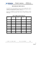
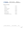
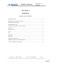
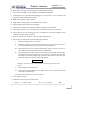
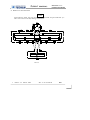
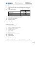
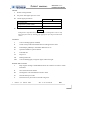
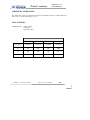
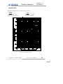
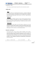
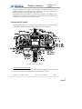
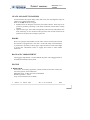
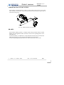
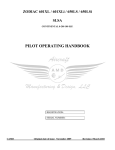
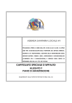
1
F LIGHT MANUAL P92Classic Deluxe INTRODUCTION FLIGHT MANUAL P92 Echo CLASSIC Deluxe MANUFACTURER : COSTRUZIONI AERONAUTICHE TECNAM S.r.l. AIRCRAFT TYPE : P92 CLASSIC deluxe. SERIAL NUMBER :............................................................... MANUFACTURING DATE :.................................................... WARNING THIS MANUAL IS VALID FOR THE P92 CLASSIC DELUXE WITH EITHER ROTAX 912 80 HP ENGINE OR ROTAX 912ULS 100 HP ENGINE. FOR EVIDENT SAFETY REASONS AND UPON READING THIS MANUAL FOR THE FIRST TIME, IT IS NECESSARY TO UNDERLINE (PERHAPS ALSO HIGHLIGHT WITH A COLORED MARKER) ANY DIFFERENCES IN CHARTS AND TABLES AS APPLICABLE TO PERSONAL AIRCRAFT. The Flight Manual must always be kept on board the aircraft. The aircraft described herein is to be operated in accordance with procedures and limitations described in this Flight Manual. 1st edition – 23th March 2009 Doc. n° 92-13-030-00 i-1 F LIGHT MANUAL P92Classic Deluxe INTRODUCTION RECORD OF REVISIONS All revisions to the current Manual, except for actual weighing data, must be recorded in the following table and, in case of approved sections, must be endorsed by the Responsible Airworthiness Authority. New text or amendments to revised pages shall be clearly marked by a vertical black line on the left hand margin, with revision N° and date indicated on left side of page. RECORD OF REVISIONS Rev N° Affected Affected Sections Pages 1st edition – 23th March 2009 Date Doc. n° 92-13-030-00 Date inserted i-2 F LIGHT P92Classic Deluxe MANUAL INTRODUCTION List of Effective Page Section Page Date th 0 i-1 i-2 i-3 i-4 i-5 23 March 2009 “ “ “ “ 1 1-1 1-2 1-3 1-4 1-5 1-6 1-7 1-8 1-9 1-10 1-11 23th March 2009 “ “ “ “ “ “ “ “ “ “ 2-1 2-2 2-3 2-4 2-5 2-6 2-7 2-8 23th March 2009 “ “ “ “ “ “ “ 3-1 3-2 3-3 3-4 3-5 23th March 2009 “ “ “ “ 2 3 1st edition – 23th March 2009 Section Page Date th 4 4-1 4-2 4-3 4-4 4-5 4-6 4-7 4-8 23 March 2009 “ “ “ “ “ “ “ 5 5-1 5-2 5-3 5-4 5-5 5-6 5-7 5-8 23th March 2009 “ “ “ “ “ “ “ 6 6-1 6-2 6-3 6-4 23th March 2009 “ “ “ Doc. n° 92-13-030-00 i-3 F LIGHT Section Page Date 7 7-1 7-2 7-3 7-4 7-5 7-6 23th March 2009 “ “ “ “ “ 8 8-1 8-2 8-3 8-4 8-5 23th March 2009 “ “ “ “ 1st edition – 23th March 2009 MANUAL Section P92Classic Deluxe INTRODUCTION Page Doc. n° 92-13-030-00 Date i-4 F LIGHT MANUAL P92Classic Deluxe INTRODUCTION TABLE OF CONTENTS General Section 1 Limitations Section 2 Emergency procedures Section 3 Normal procedures Section 4 Performance Section 5 Weight and balance Section 6 Systems description Section 7 Ground handling and servicing Section 8 1st edition – 23th March 2009 Doc. n° 92-13-030-00 i-5 F LIGHT MANUAL P92 Classic Deluxe GENERAL SECTION 1 GENERAL TABLE OF CONTENTS INTRODUCTION ....................................................................................................... 2 WARNINGS - CAUTIONS - NOTES............................................................................ 2 THREE VIEW DRAWING ........................................................................................... 2 DESCRIPTIVE DATA ................................................................................................. 3 CONTROL SURFACES TRAVEL LIMITS .................................................................. 4 ENGINE ...................................................................................................................... 5 PROPELLER .............................................................................................................. 5 FUEL ......................................................................................................................... 6 OIL ............................................................................................................................. 6 COOLING .................................................................................................................. 6 WEIGHTS .................................................................................................................. 7 SPECIFIC LOADINGS ............................................................................................... 7 ABBREVIATIONS AND TERMINOLOGY .................................................................. 8 UNIT CONVERSION FACTORS .............................................................................. 11 1st edition – 23th March 2009 Doc. n° 92-13-030-00 1-1 F LIGHT MANUAL P92 Classic Deluxe GENERAL INTRODUCTION The P92 CLASSIC DELUXE is twin seat, single engine aircraft with a strutbraced rectangular high wing, fixed main landing gear and steerable nose wheel. This Flight Manual has been prepared to provide pilots and instructors with information for the safe and efficient operation of this aircraft. This Flight Manual contains 8 sections. Section 1 provides basic data and information of general interest in addition to definitions and explanations of symbols, abbreviations and terminology commonly used. WARNINGS - CAUTIONS - NOTES The following definitions apply to warnings, cautions and notes used in the Flight Manual. WARNING means that the non-observation of the corresponding procedure leads to an immediate or important degradation of the flight safety. CAUTION means that the non-observation of the corresponding procedure leads to a minor or to a more or less long term degradation of the flight safety. NOTE draws the attention to any special item not directly related to safety but which is important or unusual. THREE VIEW DRAWINGS Dimensions shown refer to aircraft weight of 450 kg and normal operating tire pressure. Propeller clearance 360mm Propeller clearance with deflated front tire and compressed shock absorber 142mm Minimum ground steering radius 5.5m 1st edition – 23th March 2009 Doc. n° 92-13-030-00 1-2 F LIGHT 1st edition – 23th March 2009 MANUAL P92 Classic Deluxe GENERAL Doc. n° 92-13-030-00 1-3 F LIGHT MANUAL P92 Classic Deluxe GENERAL DESCRIPTIVE DATA WING Wing span: Wing chord Wing surface Wing loading Aspect ratio Taper ratio Dihedral 9.4 m 1.4 m 13.2 m2 34.2 kg/m2 6.714 1.0 1.5° FUSELAGE Overall length Overall width Overall height 6.5 m 1.1 m 2.5 m EMPENNAGE Stabilator span Vertical tail span 2.9 m 1.23 m LANDING GEAR Wheel track: Wheel base: Main gear tire. Air Trac Wheel hub and brake Marc Ingegno Nose gear tire Sava 1.8 m 1.6 m 5.00-5 4.00-6 CONTROL SURFACES TRAVEL LIMITS Ailerons Stabilator Trim-Tab Rudder Flaps 1st edition – 23th March 2009 Up 20° down 15° ± 2° Up 16° down 3° ± 1° +2° +12° 1° RS 25° LS 25° ± 1° 0° - 35° 2° Doc. n° 92-13-030-00 1-4 F LIGHT MANUAL P92 Classic Deluxe GENERAL ENGINE Model Rotax 912 UL Rotax 912 ULS Manufacturer: Bombardier-Rotax GmbH Bombardier-Rotax GmbH Engine type: Four cylinder horizontallyopposed twins with overall displacement of 1211.2 c.c., mixed cooling, (watercooled heads and aircooled cylinders), twin carburetors, integrated reduction gear, (2.273:1) with torque damper. Compression ratio: 9.0:1. Four cylinder horizontallyopposed twins with overall displacement of 1352 c.c., mixed cooling, (watercooled heads and aircooled cylinders), twin carburetors, integrated reduction gear, (2.4286:1) with torque damper. Compression ratio: 10.3:1. Maximum power: 80hp (59.6 kW ) at 5800 rpm - max 5 min. 100 hp (73.5 kW) at 5800 rpm - max 5 min. PROPELLER Manufacturer: Model: Propeller for 912 UL Propeller for 912 ULS F.lli Tonini Giancarlo & Felice S.n.c. GT-2/166/VSU-FW 101 SRTC F.lli Tonini Giancarlo & Felice S.n.c. GT-2/173/VRR-FW 101 SRTC Number of blades: 2 2 Diameter: 1660 mm 1730 mm Type: Fixed pitch - wood Fixed pitch - wood 1st edition – 23th March 2009 Doc. n° 92-13-030-00 1-5 F LIGHT P92 Classic Deluxe MANUAL GENERAL FUEL Rotax 912 UL Fuel grade: Min RON 90 EN 228 Regular EN 228 Premium EN 228 Premium plus AVGAS 100 LL (*) Rotax 912 ULS Min RON 95 EN 228 Premium EN 228 Premium plus AVGAS 100 LL (*) Fuel tanks: 2 wing tanks integrated within the wing's leading edge with drainage reservoir located in engine cowling Capacity of each wing tank 45 litres Total capacity 90 litres * See “Rotax Operator’s Manual” for more details. OIL Oil system: Forced, with external oil reservoir Oil: Lubricant specifications and grade are detailed into the “Rotax Operator’s Manual” and in its related documents. Oil Capacity: Max. 3.0 liters – min. 2.0 litres COOLING Cooling system: Mixed air and liquid pressurized closed circuit system Coolant: Coolant type and specifications are detailed into the “Rotax Operator’s Manual” and in its related documents. 1st edition – 23th March 2009 Doc. n° 92-13-030-00 1-6 F LIGHT MANUAL P92 Classic Deluxe GENERAL WEIGHTS Maximum takeoff: 450 kg Standard empty weight 289kg SPECIFIC LOADINGS Rotax 912 UL Wing Loading Power Loading 1st edition – 23th March 2009 34.2 kg/m2 5.5 kg/hp Rotax 912 ULS 34.2 kg/m2 4.5 kg/hp Doc. n° 92-13-030-00 1-7 F LIGHT MANUAL P92 Classic Deluxe GENERAL ABBREVIATIONS AND TERMINOLOGY AIRSPEED TERMINOLOGY AND SYMBOLS CAS Calibrated Airspeed is indicated airspeed corrected for position and instrument error. IAS Indicated Airspeed: is the speed shown on the on-board airspeed indicator. TAS True Airspeed: is calibrated airspeed corrected for altitude and temperature. VFE Maximum Flap Extended Speed: is the highest speed permissible with wing flaps in a prescribed extended position. VNO Maximum Structural Cruising Speed: is the speed that should not be exceeded except in smooth air, then only with caution. VNE Never Exceed Speed: is the speed limit that may not be exceeded at any time. VS Stalling Speed. VS0 Stalling Speed or the minimum steady flight speed at which the airplane is controllable in the landing configuration at the most forward center of gravity. VX Best Angle-of-Climb Speed is the speed which results in the greatest gain of altitude in a given horizontal distance. VY Best Rate-of-Climb Speed is the speed which results in the greatest gain in altitude in a given time. Vr Rotation speed: is the speed at which the aircraft rotates about the pitch axis during takeoff Vobs Obstacle speed: is the speed at which the aircraft flies over a 15m obstacle during takeoff or landing 1st edition – 23th March 2009 Doc. n° 92-13-030-00 1-8 F LIGHT MANUAL P92 Classic Deluxe GENERAL METEOROLOGICAL TERMINOLOGY OAT Outside Air Temperature is the free air static temperature expressed in degrees Celsius (°C). TS Standard Temperature is 15°C at sea level pressure altitude and decreased by 2°C for each 1000 ft of altitude. HP Pressure Altitude is the altitude read from an altimeter when the barometric subscale has been set to 1013 mb. ENGINE POWER TERMINOLOGY RPM Revolutions Per Minute: is the number of revolutions per minute of the engine’s crankshaft, divided by 2.273 (912UL) or 2.4286 (912S) yields propeller’s RPM. AIRPLANE PERFORMANCE AND FLIGHT PLANNING TERMINOLOGY Crosswind Velocity is the velocity of the crosswind component for which adequate control of the airplane during takeoff and landing was actually demonstrated. Usable fuel is the fuel available for flight planning. Unusable fuel is the quantity of fuel that cannot be safely used in flight. G is the acceleration of gravity. TOR is the takeoff distance measured from actual start to wheel liftoff point TOD is total takeoff distance measured from start to 15m obstacle clearing GR is the distance measured during landing from actual touchdown to stop point LD is the distance measured during landing, from 15m obstacle clearing to actual stop. S/R is specific range, that is, the distance (in nautical miles) which can be expected at a specific power setting and/or flight configuration per kilo of fuel consumed 1st edition – 23th March 2009 Doc. n° 92-13-030-00 1-9 F LIGHT MANUAL P92 Classic Deluxe GENERAL WEIGHT AND BALANCE TERMINOLOGY Datum is an imaginary vertical plane from which all horizontal distances are measured for balance purposes. Arm is the horizontal distance from the reference datum to the center of gravity (C. G.) of an item. Moment is the product of the weight of an item multiplied by its arm. C. G. Center of Gravity is the point at which the airplane, or equipment, would balance if suspended. Its distance from the reference datum is found by dividing the total moment by the total weight of the airplane. Standard Empty Weight is the weight of a standard airplane, including unusable fuel, full operating fuels and full engine oil. Basic Empty Weight is the standard empty weight plus the weight of optional equipment. Useful Load is the difference between takeoff weight and the basic empty weight. Maximum Weight is the maximum weight of the aircraft. Maximum Takeoff Weight is the maximum weight approved for the start of the takeoff run. Maximum Landing Weight is the maximum weight approved for the landing touch down. Tare is the weight of chocks, blocks, stands, etc. used when weighing an airplane, and is included in the scale readings. Tare is deducted from the scale reading to obtain the actual (net) airplane weight. 1st edition – 23th March 2009 Doc. n° 92-13-030-00 1-10 F LIGHT MANUAL P92 Classic Deluxe GENERAL UNIT CONVERSION FACTORS MULTIPLYING TEMPERATURE Fahrenheit [°F] Celsius [°C] FORCES Kilograms Pounds SPEED Meters per second Feet per minute Knots Kilometers / hour PRESSURE Atmosphere Pounds / sq. in LENGTH Kilometers Nautical miles Meters Feet Centimeters Inches VOLUME Liters U.S. Gallons AREA Square meters Square feet BY YIELDS 5 F 32 9 9 C 32 5 Celsius [°C] Fahrenheit [°F] [kg] [lbs] 2.205 0.4536 Pounds Kilograms [lbs] [kg] [m/s] [ft/min] [kts] [km/h] 196.86 0.00508 1.853 0.5396 Feet per minute. Meters per second. Kilometers / hour Knots [ft/min] [m/s] [km/h] [kts] [atm] [psi] 14.7 0.068 Pounds / sq. in Atmosphere [psi] [atm] [km] [nm] [m] [ft] [cm] [in] 0.5396 1.853 3.281 0.3048 0.3937 2.540 Nautical miles Kilometers Feet Meters Inches Centimeters [nm] [km] [ft] [m] [in] [cm] [l] [US Gal] 0.2642 3.785 U.S. Gallons Liters [US Gal] [l] [m2] [sq ft] 10.76 0.0929 Square feet Square meters [sq ft] [m2] 1st edition – 23th March 2009 Doc. n° 92-13-030-00 1-11 F LIGHT P92 Classic Deluxe MANUAL LIMITATIONS SECTION 2 LIMITATIONS TABLE OF CONTENTS INTRODUCTION ....................................................................................................... 2 AIRSPEED LIMITATIONS ......................................................................................... 2 AIRSPEED INDICATOR MARKINGS ....................................................................... 3 POWERPLANT LIMITATIONS .................................................................................. 4 PROPELLER .............................................................................................................. 5 POWERPLANT INSTRUMENT MARKINGS ............................................................. 6 OTHER INSTRUMENT MARKINGS .......................................................................... 7 WEIGHT LIMITS ........................................................................................................ 7 CENTER OF GRAVITY LIMITS ................................................................................. 7 APPROVED MANEUVERS ........................................................................................ 7 FUEL .......................................................................................................................... 8 1st edition – 23th March 2009 Doc. n° 92-13-030-00 2-1 F LIGHT P92 Classic Deluxe MANUAL LIMITATIONS INTRODUCTION Section 2 includes operating limitations, instrument markings, and basic placards necessary for safe operation of the P92 CLASSIC DELUXE, their engines, standard systems and standard equipment. AIRSPEED LIMITATIONS Rotax 912 UL / ULS SPEED Km/h REMARKS IAS VNE Never exceed speed 260 Never exceed this speed in any operation. VNO Maximum Structural 200 Never exceed this speed unless in smooth Cruising Speed VA Maneuvering speed air, and then only with caution. 150 Do not make full or abrupt control movements above this speed as this may cause stress in excess of limit load factor VFE Maximum flap extended speed 1st edition – 23th March 2009 110 Never exceed this speed for any given flap setting. Doc. n° 92-13-030-00 2-2 F LIGHT P92 Classic Deluxe MANUAL LIMITATIONS AIRSPEED INDICATOR MARKINGS Airspeed indicator markings and their color code are explained in the following table: Rotax 912 UL / ULS MARKING IAS km/h SIGNIFICANCE White arc 71 – 110 Flap Operating Range (lower limit is VSO, at maximum weight and upper limit is maximum speed permissible with flaps extended at 35°) Green arc 110 – 200 Normal Operating Range (lower limit is VFE at maximum weight and upper limit is maximum structural speed VNO). Yellow arc 200 – 260 Operations must be conducted with caution and only in smooth air. Red line 260 1st edition – 23th March 2009 Maximum speed for all operations. Doc. n° 92-13-030-00 2-3 F LIGHT P92 Classic Deluxe MANUAL LIMITATIONS POWERPLANT LIMITATIONS The following table lists operating limitations for aircraft installed engine: ENGINE MANUFACTURER: Bombardier Rotax GmbH. ENGINE MODELS: 912 UL / 912 ULS MAXIMUM POWER: Max Power kW (hp) Maximum (max. 5 minutes) Max RPM 912UL 912 ULS 912UL 912 ULS 59.6 (80) 73.5 (100) 5800 5500 58 (76) 69 (93) 5800 5500 Maximum - continuous TEMPERATURES: Max. Cylinder Head Temperature (max. CHT) min. / Max. Oil temperature 912 UL 912 ULS 150° C 135° C 50° - 140°C 50° - 130°C 90° - 110° C Oil normal operating temperature (approx.) OIL PRESSURE: 912 UL 0.8 bar Minimum (below 3500 rpm eng.) Normal (above 3500 rpm eng.) 912 ULS 2.0 – 5.0 bar CAUTION Admissible pressure for cold start is 7 bar maximum for short periods. 1st edition – 23th March 2009 Doc. n° 92-13-030-00 2-4 F LIGHT P92 Classic Deluxe MANUAL LIMITATIONS OIL VISCOSITY Use viscosity grade oil as specified in the following table: CAUTION Use of Aviation Grade Oil with or without additives is not permitted COOLANT: Coolant type and specifications are detailed into the “Rotax Operator’s Manual” PROPELLER PROPELLER FOR: MANUFACTURER: Rotax 912 UL Rotax 912 ULS F.lli Tonini Giancarlo & Felice F.lli Tonini Giancarlo & Felice MODEL: GT-2/166/VSU-FW 101 SRTC GT-2/173/VRR-FW 101 SRTC PROP. TYPE: Wood twin blade fixed pitch Wood twin blade fixed pitch DIAMETER: 1660 mm 1730 mm 1st edition – 23th March 2009 Doc. n° 92-13-030-00 2-5 F LIGHT P92 Classic Deluxe MANUAL LIMITATIONS POWERPLANT INSTRUMENT MARKINGS Powerplant instrument markings and their color code significance are shown below: Rotax 912 UL RED LINE GREEN ARC YELLOW ARC RED LINE Minimum Normal Caution Maximum limit limit operating RPM -------- 1400-5500 5500-5800 5800 Oil Temp. °C 50 90-110 50 - 90 110-140 140 Cylinder heads temperature (CHT) °C -------- 75 - 150 -------- 150 Oil pressure bar 0.8 2.0 – 5.0 0.8 – 2.0 5.0 – 7.0 7.0 RED LINE GREEN ARC YELLOW ARC RED LINE Minimum Normal Caution Maximum limit limit operating RPM -------- 1400-5500 5500-5800 5800 Oil Temp. °C 50 90-110 50 - 90 110-130 130 Cylinder heads temperature (CHT) °C -------- 75 - 135 -------- 135 Oil pressure bar 0.8 2.0 – 5.0 0.8 – 2.0 5.0 – 7.0 7.0 INSTRUMENT Engine tachometer Rotax 912 ULS INSTRUMENT Engine tachometer 1st edition – 23th March 2009 Doc. n° 92-13-030-00 2-6 F LIGHT P92 Classic Deluxe MANUAL LIMITATIONS OTHER INSTRUMENT MARKINGS INSTRUMENT RED LINE GREEN ARC YELLOW ARC RED LINE Minimum limit Normal operating Caution Maximum limit 10 Volt 12 - 14 Volt ------ ------ Voltmeter WEIGHT LIMITS Maximum takeoff weight: 450 kg CENTER OF GRAVITY LIMITS Forward limit 20% MAC Aft limit 33% MAC Datum Propeller support flange w/o spacer Bubble Level Cabin floor It is the pilot's responsibility to insure that airplane is properly loaded. APPROVED MANEUVERS This aircraft is è intended for non-aerobatic operation only. Non-aerobatic operation includes: Any maneuver pertaining to “normal” flight Stalls (except whip stalls) Lazy eights Chandelles Turns in which the angle of bank is not more than 60° Acrobatic maneuvers, including spins, are not approved. 1st edition – 23th March 2009 Doc. n° 92-13-030-00 2-7 F LIGHT P92 Classic Deluxe MANUAL LIMITATIONS FUEL TWO TANKS: 45 litres TOTAL FUEL CAPACITY: 90 litres Rotax 912 UL - APPROVED FUELS Min. RON 90 EN 228 Regular EN 228 Premium EN 228 Premium plus AVGAS 100LL (refer to the “Rotax Operator’s Maunal”) Rotax 912 ULS - APPROVED FUELS Min. RON 95 EN 228 Premium EN 228 Premium plus AVGAS 100LL (refer to the “Rotax Operator’s Maunal”) 1st edition – 23th March 2009 Doc. n° 92-13-030-00 2-8 F LIGHT MANUAL P92 Classic Deluxe EMERGENCY PROCEDURES SECTION 3 EMERGENCY PROCEDURES TABLE OF CONTENTS INTRODUCTION .................................................................................................... 2 ENGINE FAILURE .................................................................................................. 2 FORCED LANDING ............................................................................................... 3 SMOKE AND FIRE ................................................................................................. 3 RECOVERY FROM UNINTENTIONAL SPIN......................................................... 4 DEPLOYMENT OF EMERGENCY PARACHUTE (optional equipment) ............... 5 1st edition – 23th March 2009 Doc. n° 92-13-030-00 3-1 F LIGHT MANUAL P92 Classic Deluxe EMERGENCY PROCEDURES INTRODUCTION Section 3 includes checklists and detailed procedures to be used in the event of emergencies. Emergencies caused by a malfunction of the aircraft or engine are extremely rare if appropriate maintenance and pre-flight inspections are carried out. In case of emergency, suggestions presented in this section should be considered and applied as necessary to correct the problem. Before operating the aircraft, the pilot should become thoroughly familiar with the present manual and, in particular, with the present section. Further, a continued and appropriate training should be provided. ENGINE FAILURE Depending on the case that may apply, the emergency procedure should follow the guidelines listed below. ENGINE FAILURE DURING TAKEOFF RUN 1. 2. 3. 4. 5. 6. Throttle: idle (fully out) Brakes: apply as needed Magnetos: OFF Flaps: retract Master switch: OFF Fuel shutoff valves: OFF ENGINE FAILURE IMMEDIATELY AFTER TAKEOFF 1. Locate landing area 2. Throttle: idle (fully out) 3. Fuel shutoff valves: OFF 4. Magnetos OFF 5. Flaps: as needed 6. Master switch: OFF 7. Land with wings level 1st edition – 23th March 2009 Doc. n° 92-13-030-00 3-2 F LIGHT MANUAL P92 Classic Deluxe EMERGENCY PROCEDURES FORCED LANDING EMERGENCY LANDING WITHOUT ENGINE POWER 1. 2. 3. 4. 5. 6. 7. Set glide speed to optimal value of 110 Km/h Select terrain area most suitable for emergency landing, possibly upwind Fuel shutoff valves: OFF Magnetos: OFF Tighten safety belts, release door safety lock and unlatch doors Flaps: as needed When ready to land, Master switch: OFF POWER-ON FORCED LANDING 1. 2. 3. 4. 5. 6. 7. Adjust descent slope Extend flaps as needed Select terrain area most suitable for emergency landing and flyby checking for obstacles and wind direction Tighten safety belts, release door safety lock and unlatch doors Before touchdown: fuel shutoff valves OFF Flaps: extended After touchdown: Magnetos: OFF, Master switch: OFF SMOKE AND FIRE ENGINE FIRE WHILE PARKED OR DURING TAKEOFF 1. 2. 3. 4. 5. 6. Fuel shutoff valves: OFF Abort takeoff if possible If engine is running let it use up remaining fuel in carburetors Magnetos and Master switch: OFF Warn bystanders to clear the area as fast as possible Without removing the engine cowling use a CO2 or a powder fire extinguisher to put out flames directing spray towards cowling's air intakes 1st edition – 23th March 2009 Doc. n° 92-13-030-00 3-3 F LIGHT MANUAL P92 Classic Deluxe EMERGENCY PROCEDURES NOTE DO NOT USE WATER to put out fire and do not open engine cowling until absolutely certain fire is extinguished. In case an appropriate fire extinguisher is not handy, still keeping engine cowling closed, it is possible to use a woolen blanket, sand or dirt to try smothering the fire. ENGINE COMPARTMENT FIRE IN FLIGHT 1. 2. 3. 4. 5. 6. 7. Fuel shutoff valves: OFF Throttle: fully inward Magnetos: OFF Do not try airstarting engine Extend flaps as needed Carry out forced landing emergency procedure Master switch OFF CABIN FIRE DURING FLIGHT 1. 2. 3. 4. Master switch OFF Door vents: open Extinguish fire with on-board fire extinguisher (if available) directing spray towards flame base Land as soon as possible RECOVERY FROM UNINTENTIONAL SPIN In case of unintentional spin entry, follow the emergency procedure described below: 1. 2. 3. 4. 5. 6. Adjust throttle to minimum (full outward position) Activate rudder bar by pushing foot opposite spin direction Push control stick full forward and keep in position until spin is halted Center rudder bar Gradually recover flight attitude easing back on the control stick avoiding to exceed VNE and maximum load factor Readjust throttle to restore engine power 1st edition – 23th March 2009 Doc. n° 92-13-030-00 3-4 F LIGHT MANUAL P92 Classic Deluxe EMERGENCY PROCEDURES DEPLOYMENT OF EMERGENCY PARACHUTE (optional equipment) Keeping in mind that full deployment of parachute is achieved after two seconds, the following procedure is recommended: 1. 2. 3. 4. 5. 6. 7. Try leveling aircraft as much as possible Minimum altitude for successful deployment is about 33m (100 ft).1 Pull firing clip firmly and to end-travel Shut off fuel valves, magnetos and master switch Tighten safety belt and helmet chinstrap Release door safety lock and unlatch doors Assume tucked position before touch-down 1 This altitude is only representative,successful deployment depends on aircraft attitude and speed, greater deployment altitude yields better chances for successful deployment. 1st edition – 23th March 2009 Doc. n° 92-13-030-00 3-5 F LIGHT MANUAL P92 Classic Deluxe NORMAL PROCEDURES SECTION 4 NORMAL PROCEDURES TABLE OF CONTENTS INTRODUCTION ....................................................................................................... 2 RIGGING AND DERIGGING ENGINE COWLING .................................................. 2 PREFLIGHT INSPECTION ...................................................................................... 3 CHECKLISTS ............................................................................................................. 6 1st edition – 23th March 2009 Doc. n° 92-13-030-00 4-1 F LIGHT MANUAL P92 Classic Deluxe NORMAL PROCEDURES INTRODUCTION Section 4 contains checklists and amplified procedures for the conduct of normal operation. RIGGING AND DERIGGING ENGINE COWLING UPPER COWLING: I. Parking brake ON. II. Fuel shutoff valves OFF. III. Master switch OFF, Magnetos OFF. IV. Unlatch all four butterfly Cam-locks mounted on the cowling by rotating them 90° counterclockwise while slightly pushing inwards. V. Remove engine cowling paying attention to propeller shaft passing through nose. VI. To assemble: rest cowling horizontal insuring proper fitting of nose base reference pins. VII. Secure latches by applying light pressure, check for proper assembly and fasten Cam-locks. WARNING ! Butterfly Cam-locks are locked when tabs are horizontal and open when tabs are vertical. Verify tab is below latch upon closing. LOWER COWLING I. After disassembling upper cowling, bring propeller to horizontal position. II. Using a standard screwdriver, press and rotate 90° the two Cam-locks positioned on lower cowling by the firewall. III. Disconnect landing light wire IV. Pull out the first hinge pin positioned on the side of the firewall, then, while holding cowling, pull out second hinge pin; remove cowling with downward motion. V. For installation follow reverse procedure. 1st edition – 23th March 2009 Doc. n° 92-13-030-00 4-2 F LIGHT MANUAL P92 Classic Deluxe NORMAL PROCEDURES PREFLIGHT INSPECTION Before each flight, it is necessary to carry out a complete inspection of the aircraft as hereby detailed. CABIN INSPECTION A Weight and balance: check if within limits B Safety belts used to lock controls: free C Flight controls: activate flight controls to insure unhindered movement of control rods and surfaces. D Parking brake: engage E Master switch: ON F Check generator switch is illuminated and ammeter is operational. G Flaps control: activate control to full extension checking end travel and instrument indication. H Trim control: activate control to full scale checking end travel and instrument indication I Master switch: OFF J Fuel level: check level on the basis of flight plan EXTERNAL INSPECTION To carry out the external inspection it will be necessary to follow the checklist below with the station order outlined in fig. 4-1 A Left side tank cap: Check proper fastening. B Left fuel tank blow-out plug: check for obstructions C Remove protection cap and check pitot is unobstructed, do not blow inside vents, place protection cap inside aircraft. D Leading edge and wing skin: check integrity E Left aileron: check integrity and unhindered movement F Left flap and hinges: check integrity G Check integrity of left side main landing gear, tire inflation (1.6 bar), condition and alignment; check fuselage skin condition. 1st edition – 23th March 2009 Doc. n° 92-13-030-00 4-3 F LIGHT MANUAL P92 Classic Deluxe NORMAL PROCEDURES H Horizontal tail and tab: check integrity and unhindered movement. I Vertical tail and rudder: check integrity and unhindered movement. L Check integrity of right side main landing gear, tire pressure (1.6 bar), condition and alignment; check fuselage skin condition. M Right flap and hinges: check integrity. N Right aileron: check integrity and unhindered movement. O Leading edge and wing skin: check integrity P Check right side tank cap is fastened and blow-out plug is unobstructed. Q Check right side static vent is unobstructed, do not blow inside vents (read note). R Check integrity of nose landing gear strut, tire inflation (1.0 bar) and condition; check condition of rubber shock absorbers. S Propeller and spinner condition: check for nicks and fastening. T Open engine cowling and perform the following checklist: I. Check no foreign objects are present. II. Check the cooling circuit for losses from tubing, check coolant reservoir level, insure radiator honeycomb cooling fins are unobstructed. III. Check lubrication circuit for losses from tubing, check oil reservoir level, insure radiator honeycomb cooling fins are unobstructed IV. Open both fuel taps, inspect fuel circuit for losses from tubing, check integrity of fireproof protection braids, drain circuit using a container to collect fuel activating the specific drainage tap located on the firewall, shut fuel taps. Check for absence of water or other contaminants. WARNING ! Drainage operation must be carried out with aircraft parked on level surface. V. Check integrity of silent-blocks. VI. Check firmness and integrity of air intake system, check externally that ram air intake is unobstructed. VII. Check that all parts are secure or safetied. U Close engine cowling. V Check left side static port is unobstructed 1st edition – 23th March 2009 Doc. n° 92-13-030-00 4-4 F LIGHT MANUAL P92 Classic Deluxe NORMAL PROCEDURES Z Remove tow bar and chocks NOTE Avoid blowing inside left strut mounted pitot and inside airspeed indicator system's static vents as this may damage instruments. FIG. 4-1 1st edition – 23th March 2009 Doc. n° 92-13-030-00 4-5 F LIGHT MANUAL P92 Classic Deluxe NORMAL PROCEDURES CHECKLISTS BEFORE STARTING ENGINE (after preflight inspection) I. Flight planning, fuel consumption, refueling. II. Aircraft loading and related inspections (see section 6) III. Seat and safety belts adjustment IV. Doors secured V. Parking brake ON. STARTING ENGINE I. Master switch ON. II. Both fuel taps ON. III. Engine throttle to idle. IV. Choke as needed. V. Magnetos switch to ON. VI. Prop area: free VII. Ignition key set to: START. VIII. Engine RPM: 2000 - 2500 RPM IX. Choke OFF X. Check engine instruments XI. Check oil pressure rise (maximum value cold 7 bar) BEFORE TAXING I. Radio and utilities ON. II. Altimeter: reset. III. Navigation lights: as required TAXING I. Brakes: check operation II. Flight instruments: check operation 1st edition – 23th March 2009 Doc. n° 92-13-030-00 4-6 F LIGHT P92 Classic Deluxe MANUAL NORMAL PROCEDURES HOLDING I. Parking brake ON. II. Turn on navigation lights, strobe light, and landing light (optional equipment) III. Check engine parameters. 912 UL 912 ULS 50° - 110° C Oil temperature Max. Cylinder Heads Temperature 150° C 135° C 2.0 – 5.0 bar Oil pressure IV. Check ammeter to insure alternator is charging. V. Engine’s rpm at 4000 RPM and test magnetos. VI. Visual check of fuel indicators. VII. Flaps at 15° (takeoff) VIII. Stick free and zero trim IX. Seat belts fastened and doors secured. TAKEOFF AND CLIMB I. Control Tower for takeoff II. Check for clear final and wind on runway. III. Parking brake OFF, full throttle. IV. Carburetor heat: OFF V. Taxi to line-up VI. Rotation and takeoff VII. Slight braking to stop wheel spinning. VIII. Flaps retracted IX. Landing light OFF. X. Trim adjustment XI. Establish climb rate 1st edition – 23th March 2009 Doc. n° 92-13-030-00 4-7 F LIGHT P92 Classic Deluxe MANUAL NORMAL PROCEDURES CRUISE I. Reach cruising altitude II. Set power and engine rpm's for cruise. III. Check engine parameters 912 UL 912 ULS 90° - 110° C Oil temperature Temperature cylinder heads Oil pressure < 135° C 2.0 – 5.0 bar IV. Carburetor heat as needed, see paragraph on carb heat in Section 3. NOTE Compensate unpredicted asymmetrical fuel consumption between left and right fuel tanks by shutting off appropriate fuel tap located inside cabin LANDING I. Turn on landing light (if installed) II. Check runway final and establish descent and approach to final. III. Extend flaps gradually to maximum deflection of 35°. IV. Optimal touchdown speed 70 Km/h V. Land and taxi. VI. Flaps to 0°. VII. Parking brake ON. VIII. Turn off landing light, navigation lights and strobe light. ENGINE SHUT DOWN I. Keep engine running at 3000 RPM for about two minutes in order to reduce latent heat. II. Turn off all electrical utilities III. Set magnetos switch and Master switch to OFF IV. Set both fuel taps to OFF. V. Insert hood over pitot tube on left side wing strut. 1st edition – 23th March 2009 Doc. n° 92-13-030-00 4-8 F LIGHT MANUAL P92 Classic Deluxe PERFORMANCE SECTION 5 PERFORMANCE TABLE OF CONTENTS INTRODUCTION .............................................................................. 2 AIRSPEED CALIBRATION............................................................... 3 STALL SPEEDS ................................................................................. 3 CROSSWIND ..................................................................................... 4 TAKEOFF PERFORMANCE ............................................................ 5 LANDING .......................................................................................... 6 CLIMB PERFORMANCE ................................................................. 7 CRUISE ............................................................................................. 8 CONSEQUENCES FROM RAIN AND INSECT ............................... 8 1st edition – 23th March 2009 Doc. n° 92-13-030-00 5-1 F LIGHT MANUAL P92 Classic Deluxe PERFORMANCE INTRODUCTION This section provides all necessary data for accurate and comprehensive planning of flight activity from takeoff to landing. Data reported in graphs and/or tables were determined using: aircraft and engine in good condition average piloting techniques Each graph or table was determined according to ICAO Standard Atmosphere (ISA - m.s.l.); evaluations of the impact on performance was carried out by theoretical means for: airspeed external temperature altitude weight 1st edition – 23th March 2009 Doc. n° 92-13-030-00 5-2 F LIGHT P92 Classic Deluxe PERFORMANCE MANUAL AIRSPEED CALIBRATION The difference between indicated airspeed and calibrated airspeed is within JAR-VLA limits of 3% for all speeds above 1.3 Vs. STALL SPEEDS CONDITIONS: - weight 450 kg - engine idle - no ground effect LATERAL BANKING 0° 30° 45° 60° FLAPS IAS Km/h IAS Km/h IAS Km/h IAS Km/h 0° 74 78 84 101 15° 69 76 79 97 35° 64 69 76 91 1st edition – 23th March 2009 Doc. n° 92-13-030-00 5-3 F LIGHT MANUAL P92 Classic Deluxe PERFORMANCE CROSSWIND Maximum demonstrated crosswind velocity is 15 Kts Example: Given Find Wind direction = 30° Headwind = 17.5 Kts Wind velocity = 20 Kts Crosswind = 10 Kts Fig. 5-1 CROSSWIND CHART 1st edition – 23th March 2009 Doc. n° 92-13-030-00 5-4 F LIGHT MANUAL P92 Classic Deluxe PERFORMANCE TAKEOFF PERFORMANCE TAKEOFF DISTANCE CONDITIONS: - ISA - Engine: full throttle - Runway: dry, compact, grass - Flaps: 15° - Slope: 0° Wind: zero Fig. 5-2 TAKEOFF 1st edition – 23th March 2009 Doc. n° 92-13-030-00 5-5 F LIGHT P92 Classic Deluxe PERFORMANCE MANUAL LANDING GROUND ROLL DISTANCE AND LANDING DISTANCE CONDITIONS: - Flaps: 35° - Engine: throttle idle Runway: dry, compact, grass Slope: 0° Wind: zero Distance over a 15 m obstacle 300 Ground roll, Distance (m) 250 Ground roll 200 DISTANCE 150 100 50 0 400 410 420 430 440 450 460 470 480 490 500 WEIGHT (Kg) Fig. 5-3 LANDING 1st edition – 23th March 2009 Doc. n° 92-13-030-00 5-6 F LIGHT MANUAL P92 Classic Deluxe PERFORMANCE CLIMB PERFORMANCE CLIMB RATE IN CLEAN CONFIGURATION CONDITIONS: - ISA - Flaps: 0° - Weight 450 kg - Engine: full throttle Fig. 5-4 CLIMB RATE Rotax 912 UL VY = 120 Km/h Rotax 912 ULS VY = 120 Km/h NOTE For each 10 kg weight increase, R/C decreases by 0.15 m/sec (30 ft/min). For each 10 kg weight decrease, R/C increases by 0.15 m/sec (30 ft/min). 1st edition – 23th March 2009 Doc. n° 92-13-030-00 5-7 F LIGHT MANUAL P92 Classic Deluxe PERFORMANCE CRUISE CONDITIONS: - ISA Altitude: 0 Wind: 0 Rotax 912 UL RPM CAS km/h Hourly consumption [lt/h] 4300 155 13 4800 170 14 5000 180 16 RPM CAS km/h Hourly consumption [lt/h] 4300 165 14 4800 180 18 5000 196 20 Rotax 912 ULS CONSEQUENCES FROM RAIN AND INSECT Flight tests have demonstrated that neither rain nor insect impact build-up on leading edge has caused substantial variations on aircraft's flight qualities. 1st edition – 23th March 2009 Doc. n° 92-13-030-00 5-8 F LIGHT MANUAL P92 Classic Deluxe WEIGHT & BALANCE SECTION 6 WEIGHT & BALANCE TABLE OF CONTENTS INTRODUCTION ....................................................................................................... 2 AIRCRAFT WEIGHING PROCEDURES ................................................................... 2 WEIGHING REPORT ................................................................................................. 3 C. G. TRAVEL ............................................................................................................ 4 1st edition – 23th March 2009 Doc. n° 92-13-030-00 6-1 F LIGHT MANUAL P92 Classic Deluxe WEIGHT & BALANCE INTRODUCTION This section describes the procedure for establishing the basic empty weight and moment of the aircraft. Loading procedure information is also provided. AIRCRAFT WEIGHING PROCEDURES PREPARATION a. b. c. d. e. f. g. h. i. Carry out weighing procedure inside closed hangar Remove from cabin all objects left unintentionally Align nose wheel Drain fuel using draining reservoir Oil, hydraulic fluid and coolant to operating levels Position seats to most forward position Flaps retracted (0°) Control surfaces in neutral position Place scales (min. capacity 200 kg) under each wheel LEVELING a. b. Level the aircraft using cabin floor as datum Center bubble on level by deflating nose tire WEIGHING a. Record weight shown on each scale b. Repeat weighing procedure three times c. Calculate empty weight DETERMINATION OF C.G. LOCATION a. b. c. d. e. Drop a plumb bob tangent to the leading edge (in nontapered area of one half-wing, approximately one meter from wing root) and trace reference mark on the floor. Repeat operation for other half-wing. Stretch a taught line between the two marks Measure the distance between the reference line and main wheel axis Using recorded data it is possible to determine the aircraft's C.G. location and moment (see following table) 1st edition – 23th March 2009 Doc. n° 92-13-030-00 6-2 F LIGHT P92 Classic Deluxe MANUAL WEIGHT & BALANCE WEIGHING REPORT Model P92 CLASSIC DELUXE s/n:______ Weighing n°______ Date:_________ Datum: Propeller support flange without spacer Kg meters Nose wheel weight W1 = Plumb bob distance from LS wheel AL = LS wheel weight WL = Plumb bob distance from RS wheel AR = RS wheel weight WR = Average distance (AL+ AR)/2 A = Bob distance from nose wheel. B = W2 = WL+WR = Empty weight We = W1 + W2 = D W2 A W1 B We D% m D 100 14 . Empty weight moment: M = [(D+1.39) .We] = Maximum takeoff weight WT = Empty weight We = Maximum useful load WT - We Wu = 1st edition – 23th March 2009 Kg . m 450 kg Doc. n° 92-13-030-00 6-3 F LIGHT MANUAL P92 Classic Deluxe WEIGHT & BALANCE C. G. TRAVEL Maximum admissible C.G. travel exceeds actual operational limits. Moreover, occupants and fuel impact only marginally on CG travel. When on flat terrain, exceeding CG travel aft limit will cause aircraft tail to lower. 1st edition – 23th March 2009 Doc. n° 92-13-030-00 6-4 F LIGHT MANUAL P92 Classic Deluxe SYSTEMS SECTION 7 AIRPLANE AND SYSTEM DESCRIPTIONS TABLE OF CONTENTS INTRODUCTION .................................................................................................... 2 AIRFRAME .............................................................................................................. 2 FLIGHT CONTROLS .............................................................................................. 2 INSTRUMENT PANEL ............................................................................................ 3 SEATS AND SAFETY HARNESS ............................................................................. 4 DOORS .................................................................................................................... 4 BAGGAGE COMPARTMENT ................................................................................. 4 ENGINE ................................................................................................................... 4 FUEL SYSTEM ........................................................................................................ 5 ELECTRICAL SYSTEM ........................................................................................... 5 AIRSPEED INDICATOR SYSTEM .......................................................................... 6 BRAKES ................................................................................................................... 6 1st edition – 23th March 2009 Doc. n° 92-13-030-00 7-1 F LIGHT MANUAL P92 Classic Deluxe SYSTEMS INTRODUCTION This section provides description and operation of the aircraft and its systems. AIRFRAME WING The wing is made up of a central light alloy torque box; a composite leading edge is attached to the front spar and geometrically similar flap and aileron are hinged to rear. Flaps and ailerons are both made up of an aluminum spar connected to formed sheet metal leading edge and ribs and are covered by a thermoretractible synthetic material. FUSELAGE The front part of the fuselage is made up of a truss structure with special steel tubing and, beginning at the cabin's rear section, by an aluminum alloy semimonococque structure. The engine housing is isolated from the cabin by a stainless steel firewall; the steel stringers engine mount is attached to the cabin's truss structure in four points. EMPENNAGE The vertical tail is entirely metal: the vertical stabilizer is made up of a twin spar with load carrying skin while the rudder consists of an aluminum torque stringer connected to light alloy ribs and skin. The horizontal tail is an all-moving type (stabilator); its structure consists of an aluminum tubular spar connected to ribs and leading edge; the entire structure is covered aluminum material. FLIGHT CONTROLS Aircraft flight controls consist of aileron, rudder and stabilator control surfaces. The control surfaces are manually operated using a control stick for ailerons and stabilator and rudder pedals for the rudder; longitudinal control acts through a system of push-rods and is equipped with a trim tab. Aileron control is of mixed type with push-rods and cables; the cable control circuit is confined within the cabin and is connected to a pair of push-rods positioned in the wings that control ailerons differentially. Aileron trimming is carried out on ground through a small tab positioned on left aileron. 1st edition – 23th March 2009 Doc. n° 92-13-030-00 7-2 F LIGHT MANUAL P92 Classic Deluxe SYSTEMS Flaps are extended via an electric servo actuator controlled by a switch on the dashboard. Flaps act in continuous mode. The electric circuit is protected by a breaker positioned on the right side of the dashboard. Longitudinal trim is performed by a small tab positioned on the stabilator and controlled via an electric servoactuator by pushing an Up/Down push-button located on the control stick or between the seats. INSTRUMENT PANEL The instrument panel is of conventional type, allowing space for a broad range of equipment. Instruments marked with an asterisk (*) are optional. Fig. 7-1. INSTRUMENT PANEL THROTTLE FRICTION LOCK It is possible to adjust the engine's throttle friction by tightening appropriately the friction lock located on the dashboard near center throttle control. 1st edition – 23th March 2009 Doc. n° 92-13-030-00 7-3 F LIGHT MANUAL P92 Classic Deluxe SYSTEMS SEATS AND SAFETY HARNESS Aircraft features three point fitting safety belts with waist and diagonal straps adjustable via a sliding metal buckle. Seats on the P92 can be of two types: Standard seats are fiberglass with easily removable cushions. Seats may be adjusted on ground by operating on the latch mechanism located below seating cushion. Optional seats (type J) are built with light alloy tube structure and synthetic material cushioning. A lever located on the right lower side of each seat allows adjustment of seat position according to pilot size. DOORS Doors are equipped with handles on both sides of doors and left side external door handle is equipped with a door lock. An internal safety latch mechanism is positioned in proximity of door's upper edge and must be used before flight to secure door. Mechanism rotates to engage door frame to cabin tubular framework. BAGGAGE COMPARTMENT The baggage compartment is located behind the pilots' seats. Baggage shall be uniformly distributed on utility shelf. ENGINE Rotax 912 UL Four stroke, horizontally-opposed 4 cylinder, mixed air and water cooled, twin electronic ignition, forced lubrication Maximum rating - 81Hp (59.6 kW) at 5800 RPM Reduction gearbox - 2.273:1 Prop. GT-2/166/VSU-FW 101 SRTC 1st edition – 23th March 2009 Doc. n° 92-13-030-00 7-4 F LIGHT MANUAL P92 Classic Deluxe SYSTEMS Rotax 912 ULS Four stroke, horizontally-opposed 4 cylinder, mixed air and water cooled, twin electronic ignition, forced lubrication Maximum rating - 100 Hp (73.5 kW) a 5800 g/min Reduction gearbox - 2.4286:1 Prop. GT-2/173/VRR-FW 101 SRTC For further information, please refer to “Rotax Operator’s Manual”. FUEL SYSTEM The system consists of two aluminum fuel tanks that are integral part of the leading edge featuring a level sensor in each tank. Capacity is 45 liters each. Each tank is equipped with cabin installed shut-off valve and of a main filter located on the firewall and equipped with a drainage valve. The fuel system features a mechanical pump operated by the engine and an emergency electric pump that allows feed in case of main pump failure. ELECTRICAL SYSTEM The aircraft's electrical system consists of a 12 Volt DC circuit controlled by a Master switch located on dashboard. Electricity is provided by an alternator or by a buffer battery placed in tailcone. Generator light is located on the right side of the instrument panel. OIL AND CYLINDER HEADS TEMP. - OIL PRESSURE These instruments are connected in series with their respective sensors. Temperature instruments are protected by the same breaker; oil pressure indicator and a second breaker protects other instruments. AVIONICS The central part of the dashboard holds room for avionics equipment. System's manufacturer furnishes features for each system. 1st edition – 23th March 2009 Doc. n° 92-13-030-00 7-5 F LIGHT MANUAL P92 Classic Deluxe SYSTEMS AIRSPEED INDICATOR SYSTEM The aircraft's airspeed indicator system is shown below and consists of two static vents located on both sides of the aircraft forward of cabin and by a pitot tube located on left wing strut FIG. 7-2. AIRSPEED INDICATOR SYSTEM BRAKES The aircraft's braking system is a single system acting on both wheels of main landing gear through disk brakes, the same circuit acts as parking brake via an intercept valve. To activate brakes it is sufficient to verify that brake shut-off valve positioned on tunnel between pilots is OFF, then activate brake lever as necessary. To activate parking brake pull brake lever and set brake shut-valve to ON. 1st edition – 23th March 2009 Doc. n° 92-13-030-00 7-6 P92 Classic Deluxe F LIGHT MANUAL GROUND HANDLING AND SERVICE SECTION 8 GROUND HANDLING AND SERVICE TABLE OF CONTENTS INTRODUCTION .................................................................................................... 2 AIRPLANE INSPECTION PERIODS ...................................................................... 2 GROUND HANDLING ............................................................................................ 2 GROUND ROUND ANCHORAGE (Optional) ....................................................... 4 CLEANING AND CARE .......................................................................................... 5 1st edition – 23th March 2009 Doc. n° 92-13-030-00 8-1 P92 Classic Deluxe F LIGHT MANUAL GROUND HANDLING AND SERVICE INTRODUCTION This section contains factory-recommended procedures for proper ground handling and routine care and servicing. It also identifies certain inspection and maintenance requirements which must be followed if the aircraft is to retain its newplane performance and dependability. It is wise to follow a planned schedule of lubrication and preventive maintenance based on climatic and flying conditions encountered locally. AIRPLANE INSPECTION PERIODS Inspection intervals occur at 50, 100 hours and in accordance with special inspection schedules which are added to regularly scheduled inspections. Correct maintenance procedures are described in the aircraft’s Service Manual or in the engine’s Service Manual. GROUND HANDLING TOWING The aircraft is most easily and safely maneuvered by hand by pushing on wing struts near attachments or by pulling it by its propeller near the axle. A tow bar can be fixed onto nose gear fork. Aircraft may be steered by turning rudder or, for steep turns, by pushing lightly on tailcone to lift nose wheel. PARKING AND TIE-DOWN When parking airplane outdoors, head it into the wind and set the parking brake. If chocks or wedges are available it is preferable to use the latter. In severe weather and high wind conditions it is wise to tie the airplane down. Tie-down ropes shall be fastened to the wing strut attachments and anchoring shall be provided by ramp tie-downs. Nose gear fork can be used for front tie-down location. Flight controls shall be secured to avoid possible weathervaning to end travel damage of moving surfaces. For this purpose, seatbelts may be used to latch control stick to prevent its movement. 1st edition – 23th March 2009 Doc. n° 92-13-030-00 8-2 P92 Classic Deluxe F LIGHT MANUAL GROUND HANDLING AND SERVICE JACKING Given the light empty weight, lifting one of the main wheels can easily be accomplished even without the use of hydraulic jacks. It is in fact sufficient that while one person lifts one half-wing by acting on the spar immediately before the wingtip, another person places a suitable stand below the steel spring attachment. LEVELING Aircraft leveling may become necessary to check wing incidence, dihedral or the exact location of CG. Leveling is obtained when the lower cabin edge and the main gear support beam are horizontal. ROAD TRANSPORT It is recommended to secure tightly all aircraft components onto the cart to avoid damage during transport. Minimum cart size are 7x2.5 meters. It is suggested to place wings under the aircraft’s bottom, secured by specific clamps. Secondary components such as stabilators and struts shall be protected from accidental hits using plastic or other material. For correct rigging and derigging procedure, refer to Service Manual. 1st edition – 23th March 2009 Doc. n° 92-13-030-00 8-3 P92 Classic Deluxe F LIGHT GROUND HANDLING AND SERVICE MANUAL GROUND ANCHORAGE (OPTIONAL) The airplane should be moored for immovability, security and protection. FAA Advisory Circular AC 20-35C, Tiedown Sense, contains additional information regarding preparation for severe weather, tiedown, and related information. The following procedures should be used for the proper mooring of the airplane: 1. 2. 3. 4. 5. Head the airplane into the wind if possible. Retract the flaps. Chock the wheels. Lock the control stick using safety belts. Secure tie-down ropes to the wing tie-down rings and to the tail ring at approximately 45-degree angles to the ground, in longitudinal direction (see Fig.8-1). Tie Down Anchor Tie Down Ring Tie Down Rope Tie Down Anchor Tie Down Ring Tie Down Anchor Tie Down Rope Tie Down Rope Tie Down Ring Tie Down Anchor Tie Down Anchor Fig. 8-1. CABLE POSITIONING 1st edition – 23th March 2009 Doc. n° 92-13-030-00 8-4 P92 Classic Deluxe F LIGHT MANUAL GROUND HANDLING AND SERVICE CLEANING AND CARE To clean painted surfaces, use a mild detergent such as shampoo normally used for car finish; use a soft cloth for drying The plastic windshield and windows should never be dusted when dry; use lukewarm soapy water and dry using chamois only. It is possible to use special glass detergents but, in any case, never use products such as gasoline, alcohol, acetone or other solvents. To clean cabin interior, seats, upholstery and carpet, it is generally recommended to use foam-type detergents. 1st edition – 23th March 2009 Doc. n° 92-13-030-00 8-5