1
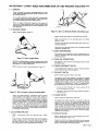
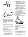
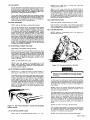
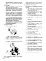
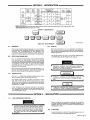
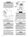
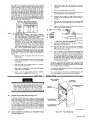
August 1973
FORM: OM-313
Effective with serial No. 72-61 2483
MODEL
MODEL/STOCK NO.
SERIAL/STYLE NO.
OWNERS
Two
Fifty Twin
Two
Fifty
Twin-P
STOCK NO.
901 973
901 976
DATE PURCHASED
MANUAL
MILLER ELECTRIC MFG. CO.
APPLETON, WISCONSIN, USA 54911
ADDITIONAL COPY
PRICE 60 CENTS
NWSA CODE NO. 4579
U.S
...
TABLE OF CONTENTS
Page No.
Paragraph No.
SECTION 1
SAFETY RULES FOR OPERATION OF ARC WELDING MACHINE
1-1. General
1 -2.
Welding
1 -3.
Electrode Holder
1
Cables
1
1
4. Code Conformance
-
1
1
1 -5. Parallel Connections
1
1
1
6. Power Disconnect Switch
-
1-7.
1
1
Polarity Switch
Range Switch
8.
-
1
1
9. Exhaust Gases
-
1
1-10. Power Circuit Ground
2
1-11. Containers Which Held Combustibles
2
1-12. Hollow Castings (Welding of)
1-13. Explosion Hazards
2
1-14. Ventilation
2
1-15. Solvents
3
1-16. Fire Hazards
3
1-17. Electrical Shock-Voltage
1-18. Electrical Shock-Dampness
3
1-19. Starting Under Load
1-20. Face Protection
3
1-21. Eye Protection
1-22. Clothing
3
1-23. Hot Metal Burns
4
4
Grinding and Chipping
1-25. Compressed Gas Cylinder
4
4
INTRODUCTION
2-1. General
2
-
2
-
2.
5
.5
Receiving-Handling
Description
Safety
3.
2 -4.
SECTION 3
5
5
INSTALLATION
3-1. Line Disconnect Switch
3
3
3
-
-
-
Primary Connections
Welding Connections
4. Secondary
-
1.
4
4
4
-
-
-
8
Duty Cycle
5. Volt-Ampere Curve
8
4.
6
6
6
-
-
-
-
8
SEQUENCE OF OPERATION
1. Shielded Metal-Arc
Welding (SMAW)
8
MAINTENANCE
SECTION 6
6
7
3. On-Off Power Switch
SECTION 5
5
6
7
Range Selector Switch
4-2. Fine Current Control & Current Indicator
-
6
OPERATION
SECTION 4
4
5
5
2. Location
3.
3
3
1-24.
SECTION 2
2
1. Power Factor Correction
Capacitors
8
2. Transformer
9
3. Fan Motor
9
4.
Input
SECTION 7
PARTS LIST
Power & Welding Cables
TROUBLESHOOTING
9
SECTION
1
-
1- SAFETY RULES
FOR OPERATION OF ARC WELDING MACHINE
1. GENERAL
These rules
apply to ac and dc welding generators. ac trans
former and ac/dc welding machines, and dc transformer recti
fier welding machines.
In
arc-welding operations, where electrically energized parts
exposed, observe the following safety rules to insure max
imum personal safety and protect nearby persons.
are
Failure to observe these safety precautions may expose not
only you, but fellow workers as well, to serious injuries. Once
these rules are learned and kept in mind, proceed with maxi
mum assurance.
1 -2. WELDING CABLES
DONT
overload
Figure
cables, (Figure 1-1)
1-3. Dont
DONT
use
use
Electrode Holder with defective
jaws
electrode holder with loose cable connections.
Keep the connections of
tight at all times.
the
electrode
lead to the holder
fully insulated electrode holders (and without
truding screwheads.)
Use only
Never touch two electrode holders from two separate
machines at the same time.
pro
welding
1 -4. CODE CONFORMANCE
The machine and its equipment must be installed and main
tained in accordance with the National Electrical Code and
local requirements.
Figure
1-1. Dont
overload cables
1 -5. PARALLEL CONNECTIONS
NEVER
use welding cables at currents in excess of their rated
capacity. It will cause overheating and rapid deterioration of
the insulation. It is also uneconomical.
See
1
DONT
use worn or
diagrams
-
in the instruction manual
applying
to
the weld
machine used.
ing
6. POWER DISCONNECT SWITCH
poorly connected cables. )Figure 1-2)
If the
welding machine does
switch, install
one at or near
not include
the machine.
a
power disconnect
1 .7. POLARITY SWITCH
DONT
operate the polarity switch under load.
The polarity switch (when supplied) is provided for changing
the electrode lead from positive (reverse polarity) to negative
(straight polarity). Never move it while under the load of a
welding current. Operate this switch only while the machine
is idling and the welding Circuit 5 open. The potential dan
gers of opening the Circuit while carrying high current are:
Figure 1-2. Dont
use worn or
The person throwing the switch may receive
from this arcing.
surfaces of the
a severe
burn
the
sections of
cable
objects, causing
an
come
arc.
in
contact
Unprotected
with
eyes
DONT
The
operate the range switch under load.
range switch
lwhen supplied)
is provided for obteining
It must never be operated while the
the load of welding current. Operate the
range switch only while the machine is idling and the welding
circuit is open. The potential danger of switching the Circuit
while carrying high current is the formation of an arc be
required
grounded metallic
may be injured and
current
settings.
machine is under
fire may result if combustible materials such as oil or grease
are in the vicinity. The efficiency and quality of welding will
be improved by elimination of these dangerous grounds, and
by keeping connections tight.
-
2.
contact
1- 8. RANGE SWITCH
insulation with rubber and friction tapes. Tighten all
cable connections and adequately insulate any joints where a
connector may have an exposed conductive part. In addition
to the potential hazard to life, a hazard occurs when exposed
1
An arc will form between the
switch and severely burn them.
poorly connected cables
Inspect the cables frequently. Immediately repair all breaks
in
1.
the contact surface which will severely burn them.
Repeated occurrences of this arcing will eventually prevent
operation of the contacts.
tween
3. ELECTRODE HOLDER
1
DONT
use
electrode
holders
with
defective
jaws.
-
9. EXHAUST GASES
(Figure
1-3)
DONT
ing
Keep the jaws of the electrode holder tight and the gripping
surfaces in good condition to provide close contact with the
electrodes. Defective jaws will permit the electrode to wob
ble, making control of the welding operations difficult.
use gas engine units in Confined spaces without vent
the exhaust gases. )Figure 1-4)
If gasoline or other fuel
indoors, provide means
driven
to
welding machines are operated
pipe the exhaust gases to the Out
side air to avoid carbon monoxide
poisoning.
OM-313 Page 1
When you know the container held
not readily dissolve in water:
-~
1.
Clean
out
thouroughly with
a
steam
liquid
or
gas
or
a
which will
cleansing agent
and purge all air or inert with a gas such as carbon dioxide
or nitrogen before repairing. Carbon dioxide is heavier
than air and will tend
opening is at the top.
2.
3.
Use steam
Use
or
4.
a
light
material,
strong caustic soda solution
to
clean out
heavy
Be
sure
or
Be
oils
to purge all air or inert with a gas, such as nitro
carbon dioxide, no matter how well you have
cleaned. There may still be traces of oil, grease,
readily oxidizable material under the seams.
Vent exhaust gases
careful
when
cleaning with
steam
or
or
caustic soda
other
wear
goggles and gloves.
1-10. POWER CIRCUIT GROUND
DONT
use welding machine without grounding frame
(Figure 1-5)
case.
clean out
in the container if the
grease.
gen
Figure 1-4.
to
remain
to
or
DONT
clean where there is poor ventilation.
Ventilation
is necessary
to
carry away harmful
or
explosive
vapors.
DONT
When
use a
clean where there
are
open flames.
scraping or hammering to remove heavy sludge or scale,
spark resistive tool and keep it wet to avoid sparks.
Keep your head and
possible,
arms
as
far away from your work
as
1-12. HOLLOW CASTINGS
DONT
weld on hollow (cored) castings that have not
properly vented. The casting may explode. (Figure 1-6)
______--Figure 1-5. Ground frame
been
or case
Ground the ground cable of every power Circuit to prevent
shock by stray current. The potential danger is
that development of a stray current may give a fatal shock
should a person, for example, place one hand on the welding
machine and the other on the switch box, or other grounded
accidental
equipment.
Do
not
ground
pipelines carrying gases
to
S
I
/
or
conduits carrying electrical conduc
liquids
tors. Be sure conductors can safely carry the ground current.
When connecting the welding machine, properly ground the
machine frame or case.
flammable
and
1-11. CONTAINERS WHiCH HELD COMBUSTIBLES
weld on containers which have held combustible or
DONT
flammable materials or materials which, when heated, give
off ftammabte or toxic vapors without proper cleaning, purg
ing,
or
inerting.
containers which have held flammable
Welding
or
combust
ible materials may be extremely dangerous. To prevent a fire
or explosion of the container, follow the recommendations
Cutting
Welding Society Pamphlet A6.O Welding
Containers Which Have Held Combustibles.
DONT
depend
of the American
weld
on a
on
your eyes
nose
or
to
1-6. Dont
Figure
weld
on
hollow (cored) castings
1-13. EXPLOSION HAZARDS
or
decide if it is safe
to
closed container.
Find Out what was in the container or use an explosimeter. A
small amount of residual flammable gas or liquid can
NEVER weld in or near explosive atmospheres. Such atmos
can be created by flammable gas leaks or by vapors
from flammable liquids (gasoline, alcohol, etc.) or by com
bustible dusts.
pheres
1.14. VENTILATION
very
cause a
serious explosion.
NEVER
use
DONT
oxygen to ventilate
a
container.
When you know the container held
readily dissolve in water:
1.
a
gas
out
as
permit introduction of
as
will
as
1967.
Always provide adequate ventilation by blowers, air
other acceptable means: Never use compressed ox
ygen. The depletion of the oxygen supply, the heat of weld
or
ing, and the fumes
serious illness.
given off
Before
welding
be
sure
there is
vide for release of air pressure.
Page
2
a
may
cause severe
discomfort
or a
possible.
When toxic fumes from lead
2.
ventilation.
welding in confined spaces, provide ventilation in
accordance with United States of American Standard Z49.1,
lines,
much water
adequate
When
liquid which
or
with water several times and then fill with
far as work permits, positioning container to
Flush
water
weld in confined spaces without
vent or
opening
to pro
or cadmium bearing materials or
other substances are present in harmful concentrations,
always use an air supplied respirator.
any
1-15. SOLVENTS
Do
electrode on the table top
metallic surface. (Figure 1-7)
greasing,
Do not weld where ultraviolet
light from the electric arc can
containing even minute amounts of vapors from
as trichloroethylene or perchloroethylene. Ul
traviolet light can decompose the vapors to form phosgene, a
highly toxic gas and other irritating products.
penetrate air
~olvents such
1-16. FIRE HAZARDS
weld
DONT
near
can
flammable
or
combustible materials.
be caused
metal, by slag,
When
is
it
not
in
contact with the
grounded
use,
place
never
tabletop
or
electrode holder in
an
other metallic surface in contact
with welding ground. Provide an insulated hook or holder for
the electrode holder. A potential danger is that a holder in
contact with the ground circuit provides a dead short circuit
on the welding machine. If the machine should be started up,
this short circuit would cause an excessive load on the ma
chine and may damage the insulation.
1-20. FACE PROTECTION
DONT
by the arc, by contact with the heated
sparks. Keep combustibles at least 35 feet
from the arc or suitably protected. If welding must be done
in a particular area, move the combustibles away. If they
cannot be moved, cover them completely with fire resistive
screens. Cover cracks or openings in floors or walls; sweep
floor free of combustibles and wet down, if wood, being sure
welder wears insulation shoe coverings. Avoid welding on par
Fires
a
weld where chlorinated
hydrocarbon vapors from de
cleaning, or spraying may reach or be drawn into air
surrounding the welding operation. The heat of the arc can
decompose solvent vapors to form phosgane, a highly toxic
gas and other irritating decomposition products.
not
in contact with
or
use
cracked or defective helmets
or
shields.
Keep the helmet, hand shields, or face shield in good condi
tion. If cracks occur in the fibre material, replace the shield,
since the leakage of arc rays may cause serious burns.
or
1-21. EVE PROTECTION
NEVER
circumstances, look
under any
at
an
electric
arc
protection.
without eye
tition walls in contact with combustibles. Heats metal on
the other side of partition wall being weded upon can ignite
combustibles in contact with the partition. Where other than
minor fire might develop, have a fire watcher stand-by with
suitable fire extinguishing equipment for at least one-half
hour after the welding is completed.
a
1-17. ELECTRICAL SHOCK-VOLTAGE
OPEN power circuits before
checking machines.
Before working on the wiring, switches, controls, etc., open
the power line disconnect switch. In most welding shops the
power supply used for arc welding machines is 230 or 460
volts, Open
welding or
voltages are usually less than 100 volts and
voltage drops are still lower. However, all of
these voltages are capable of developing a harmful or fatal
current to the body.
DONT
circuit
arc
touch electrically hot
parts.
NEVER touch any exposed or non-insulated part of the
cables, cable connectors, clamps, electrode holders, elec
trodes, or the power supply equipment to prevent harmful or
fatal electric shock
or
Figure 1-8, Use
eye
protection
at all times
burns.
1-18. ELECTRICAL SHOCK-DAMPNESS
NEVER work in a damp area without suitable insulation a
gainst shock. Keep hands, feet, and clothing dry at all times.
To.prevent harmful body shocks, keep hands, feet and cloth
ing dry. Never stand or lie in puddles of water, damp ground,
or against grounded metal when welding without suitable in
sulation against shock. Always find a dry board or rubber
mat to stand on when water, moisture, or perspiration cannot
be avoided. Dampness between the body and an energized or
grounded
current
to
metallic part lowers the resistance to the passage of
the body which may produce a harmful or fatal
shock. Salt in perspiration
contact resistances.
sea
or
water
dangerously lowers
U
I
Make
sure
goggles are used under the weld
all times, particularly while gas shielded-
that flash
ing helmet at
welding.
arc
I
I
In some type of arc welding, such as gas shielded-arc welding,
ultra-violet and infra-red radiation from the arc is particularly
intense and requires constant attention to avoid arc flashes to
the
welder when
striking
an
arc
and to avoid exposure to
other welders.
NEVER strike an arc without ascertaining that nearby per
either have the necessary protective equipment or are
looking in the opposite direction.
sons
For
in open areas, provide portable, nonshield persons nearby from the rays of
Eye burns from the arc, through not generally per
injuries, are exceedingly painful. Such burns fre
welding operations
ref Iecting
the
arc.
manent
screens
quently referred
If the eye
to
to as
is focused
flashes,
on
the
feel like hot sand in the eye.
without filter-glass protec
cause retinal scarring and im
arc
tion, infra-red radiation can
paired vision. For eye burns consult
your first aid station
or
doctor.
NEVER
Figure
1-7, Dont
leave electrode in contact with
metallic surface.
leave
an
uninsulated
electrode
or
defective plates.
and shields must
be of
the latest Ameri
glass plate provided in the helmets
reputable manufacture conforming to
National
cracked
holder,
cracked, ill-fitting,
The filter
can
1-19. STARTING UNDER LOAD
DONT
use
grounded
or
a
live
NEVER
or
Standards
ill-fitting
use
Institute, Standard Z2.1.
filter plates
filter plates.without
Replace
promptly.
a
protecting
cover
glass.
OM-313 Page 3
Keep a clean cover glass in front of the filter plate for the
protection thereof. Frequent renewal of these cover glasses is
necessary, since they become covered with spatter, reducing
vision.
Whenever it is necessary to grind or chip metal, wear protec.
tive goggles specifically designed for this purpose. Serious eye
injuries may result from failure to wear protective goggles.
1-25. COMPRESSED GAS CYLINDERS
1-22. CLOTHING
NEVER
NEVER
use
inadequate,
poor,
or
worn-out
clothing.
Wear
heavy shoes, tightly laced. Keep clothing dry.
Proper
strike
an
arc
on
compressed gas cylinder. Always
in regards to compressed
a
following precautions
observe the
g~ cylinders:
and
dry, oil-free clothing is essential for the welders
protection. Clothing must not only keep off the spatter and
molten particles, but must also obstruct the rays of the arc
and, when necessary, insulate the body from harmful electri
1.
Avoid accidental contact of the electrodes, electrode
holder, or other electrically energized parts with a
compressed gas cylinder or any other pressure vessel.
Serious accidents
fires may result.
or
cal currents.
2.
Wear leather or asbestos gloves at all times to protect the
hands and wrists. Dark colored shirts are preferred to light
because light ones reflect arc rays to exposed parts of
body. In the case of gas shielded-arc welding, light colors
ones
the
Use I.C.C.
or DOT. cylinders. They are manufactured
maintained in accordance with DOT. require
and are safe so long as they are properly
ments
hayidled. Dont drop cylinders.
and
reflective and may cause eye burns due to the in
ultra-violet rays given of f by the process. Avoid cotton
fabrics when gas shielded-arc welding.
3.
Identify gas content by the name marked on the cylin
der. If the cylinder is unmarked, do not use it. Return
it to the supplier. Do not rely on a color code.
An
4.
Never use a cylinder
intended purposes.
are
more
tense
arc
burn
usually
on
the skin resembles
more severe.
Clothing
can
a sunburn, except that it is
be made flame resistant by
its contents for other than
or
treatment with a
solution of 3/4 pound of sodium stannate in
gallon of water, then wrun9 out and dipped in a solution of
1/4 pound ammonium sulphate per gallon of water. Dont
wash clothing so prepared in water, but dry clean.
1
5.
6.
Keep
slag,
When
welding operations are to be performed in vertical and
overhead positions, leather sleevelets. aprons, and in some
cases leggings and ear plugs should be used to prevent severe
away from oxygen
cylinders and
valves.
cylinders away from exposure to sparks, hot
open flame and all possible sources of ignition or
excessive heat.
7.
burns from spatter and molten metal.
Keep oil and grease
cylinder
Be careful that cylinders are not placed so as to be
a part of an electrical circuit. Avoid third rails,
come
1-23. HOT METAL BURNS
NEVER pick up hot
wires and electric
8.
objects. (Figure 1-9)
9.
Figure 1-9.
Never
pick
up hot
objects
NEVER pick up pieces of metal which have just been welded
or heated, or the stub ends of electrodes which have been
discarded.
transporting cylinders by
When
form
welding circuits.
or
crane,
use
cradle plat
other suitable support.
Never lift the cylinders by
electric magnets.
slings, by
the caps
or
by
10.
Never
11.
Never try to mix any gases in
12.
Never try to refill
13.
Mark
14.
Send Emptys
back to the
15.
Keep Emptys
and Fulls
16.
Never tamper with or alter cylinder numbers or other
markings. This is not only foolish but may be illegal.
17,
Do not tamper with
18.
If valves cannot be
use
or
cylinders
a
supports
as
a
or
rollers.
cylinder.
cylinder.
tag empty cylinders Empty
or
or
MT.
supplier promptly. 15,
separate.
change fittings
on
cylinders.
1-24. GRINDING AND CHIPPING
NEVER
do
any chipping
goggles. (Figure 1-10)
or
grinding
without
mer or
protective
wrench.
opened by hand,
Notify supplier,
do not
use
ham
19.
Protect cylinder valves from bumps, falls, falling ob
jects, and from weather. Keep them covered with
cylinder caps when moving cylinders.
20,
Keep valves closed
21.
See that your cylinders are clear of passageways and
active work areas and that they are secured against
on
empty cylinders.
falling,
22.
If
adapter
23.
Figure 1-10. Never do
protective goggles.
Page 4
any
chipping
or
grinding without
is
required between cylinder and regulator,
standard adapter. These may be obtained
from your supplier. Where right and left hand threads
are used on adapter, use two wrenches to insure leak
proof connections.
always
use
a
Do not store
cylinders in
unventilated
areas.
SECTION 2-INTRODUCTION
.
Model
Welding
Mao.
Rated
Current
Open
Wsldieg
Ranges
Ciruuit
Current
Amperes
Vollugo
Amperes
Amperes Input At Ruled
LoS Output 60Hz.
Oimensions
hoe
kw
45
20.7
11.8
35
16.1
8.2
208)260 Vults
230 Volts
460 Volts
103
90
go
io
78
65
34
15.6
11.8
~y
5~
25
11.5
8.2
Inches)
250W
30 Volts,
Power
30% Outy Cycle
200 @
ec
Poctor
Low 25-125
oc
78
dc
dc
25051
Low 20-88
75
30 Volts.
With
High 70-250
Power
50% Ooty
Cycle
H
ht
Wdth
0 ~ th
-
332
342
-
-
340
350
26-1/4
15
25
30% Ouly Cycle
20051
Pector
.
28 Volts,
Correction
Ship
~
28 Volts,
High 105-325
Net
.
Without
Correction
Weight
Ooerull
50% Outy Cycle
~NEMA RATIN~jthe
and
above electrical specifications Conform with
comply with ANSI Standard C87.1-1971.
Rating EW 1-1971, Nema Class 11(30)
Nema
Figure 2-1. Specifications
AA-gol g73-4
Figure
2-1.
2-2.
GENERAL
Block
Diagram
24.
Before the equipment is put into operation, the safety sec
tion at the front of this manual should be read completely.
This will help avoid possible injury due so misuse or improper
prepared especially for use in familiar
design, installation, operation, main
and
tenance,
troubleshooting of this equipment All
information presented herein should be given careful con
sideration to assure optimum performance of this equipment
This manual has been
izing personnel
2-2.
SAFETY
with the
welding applications.
The
RECEIVING-HANDLING
following
definitions apply to
and NOTE blocks found
CAUTION,, IMPORTANT,
throughout this manual:
Prior to installing this equipment, clean all packing material
from around the unit and carefully inspect for any damage
that may have occurred during shipment. Any claims for loss
or damage that may have occurred in transit must be filed by
the purch~er with the carrier. A copy of the bill of lading
and freight bill will be furnished by the carrier on request if
occasion
to
file claim arises.
requesting information concerning this equipment, it is
essential that M0%Jel Designation and/or Stock Number and
Serial (or Style) Number of the equipment be supplied.
When
2-3.
~.
DESCRIPTION
This
unit
which
is
a
produces
single phase powered welding power
both ac and dc welding current.
source,
I
welding power source is capable of operation on either
200, 230 or 460 volt 60 Hertz primary electricel power.
Jumper links are provided with the welding power source for
the purpose of matching the machine to one of the above
available input voltages.
I
NOTE
Proper
installation can contribute materially to the satisfac
tory and trouble-free operation of the welding power source.
It is suggested that each step in this section be studied care
fully and followed in detail.
SECTION 3
-
Installation, operating, and maintenance procedures,
practices, etc., which will result in damage to equipmen t.
This
3-1.
Installation, operating, and maintenance procedures,
practices, etc., which will result in personnel injury or
loss of life if not carefully followed.
Installation, operating, and maintenance procedures,
practices.
etc., which it is essential to
emphasize
INSTALLATION
LINE DISCONNECT SWITCH
CAUTION
I
A precautionary measure should be
toprovide
maximum protection against electrical shock. Before
electrical connections are made from the switch, be
sure that the line disconnect switch has been opened
or
the
and
primary input circuit fuses have been removed
remain
completed.
that way until the installation has been
.
Proper installation can contribute materially to the satisfac
tory and trouble.free operation of the welding machine. It is
suggested that each step in this section be studied carefully
and followed in detail.
3-2.
LOCATION
A
to
good installation is essential if the welding power
provide satisfactory and dependable service.
source
OM-313
is
Page
5
~ldi ng
p owe r
the front and
~e
should be loca ted
so
PRIMARY CABLE
PRIMARY VOLTAGE
INPUT HOLE
JUMPER LINKS
that
panels with the air vents are clear of
any obstruction. Cooling air is drawn in through the
front upper air vent and expelled Out of the rear panel
rear
air vent.
The location should be such that a minimum amount of dust
and dirt will be drawn into the air stream. Preventive main
tenance consists of removing the wrapper from the welding
power source and blowing Out the dust accumulation inside
the unit. For this reason it is desirable to locate the unit so
that the wrapper can be removed without any difficulty.
LINE
DISCONNECT
SWITCH
3-3/8
GROUND
CONNECTION
AC-901 973.3
Figure
3-2.
Primary Connections
.
The stud
connected~ welding
CR0 is
and is
labeled
chassis
for grounding purposes
not connect a wire from the terminal labeled
either
to
one of the single phase line terminals as
this will result in an electrically hot welding power
power
source
only. Do
GAD
source
The standard welding power source is
designed to operate on
either 200, 230 or 460 volts, 60 Hertz primary electrical
This
machine was shipped from the factory with the
power.
jumper links arranged for the highest voltage the machine has
been designed to operate on. To
setup the welding power
source for the voltage to be used, position the
jumper links,
located on the primary terminal board, as shown in
Figure
3-3.
Figure 3-1, Dimensional Drawing
3-3.
chassis.
200
PRIMARY CONNECTIONS
(208) VOLTS
230 VOLTS
460 VOLTS
o~o
oo~~
~oo~
This ac/dc arc welding power source is a single phase unit and
be connected to a single phase power line. Consult the
local public electric utility if there is any question about the
must
system used
locally or the proper connections necessary to
single phase power service to the welding power
connect
0
0
0
GA.
LI
17
00
Gfl
LI
0.
00
0
12
60
17
II
A-OlO 586
Figure 3-3. Primary Voltage Jumper Link Arrangement
source.
NOTE
~ver
a ne
on ly
umper link con nection is nec
essary to obtain the proper input voltage connections,
such as 460 volts, connect both jumper links across
the same two terminals. This will prevent losing the
It is recommended that the
primary leads be of the
heavy rubber covered type or run in solid or flexible
conduit. Select the proper size primary fuse and cable
from Table 3-1.
Table 3-1.
Primary
200V
230V
460V
WIhoot P,F.C.
No. 2
No.2
With P.F.C.
No. 3
No.4
18)
(8)
(8)
Numbers in (I indicate
3-4.
Wire and Fuse Size
PRIMARY WI RE SIZE IAWGI
MODEL
FUSE SIZE IN AMPERES
57Ev
200V
230V
No.6
No.8
150
No.8
No. 10
125
second jumper link.
460V
57EV
150
70
60
100
50
40
(8)
ground wire size.
SECONDARY WELDING CONNECTIONS
It is recommended that the welding cables be kept as short as
close together and be of adequate current
carrying capacity. The resistance of the welding cables and
possible, placed
connections cause a voltage drop which is added to the volt
age of the arc. Excessive cable resistance may result in over
loading as well as reducing the maximum current output of
which the welding power source is capable.
operation of any arc welding power source is to a
great extent dependent on the use of welding cables and
connections that are in good condition and of adequate size.
An insulated holder must be used to ensure the operators
The proper
Insert the two primary leads plus one ground lead through
the access hole provided on the lower left portion of the rear
panel. See Figure 3-2 for hole location. This 1-3/4 inch dia
meter hole will accept standard conduit fittings.
primary leads are to be connected to terminals Li
and L2 on the primary terminal board (TEl), which is
located behind the primary access door on the rear panel.
The ground lead must be connected to the stud on the pri
mary terminal board labeled GAD. The remaining end of the
safety.
The two
ground
as:
a
lead should be connected to a suitable ground such
pipe, ground rod, etc. Use whatever grounding
is acceptable to the local electrical inspection
water
means
authority.
Page 6
Id in gw~h ac, if the
cables a re coiled
they will generate a magnetic field that will seri
of
affect
the
the welding power
operation
ously
source. Always lay the welding cables out.
up
Use Table 3-2 as a guide for selecting the Correct welding
cable size (or the anticipated maximum weld current that will
be used. Table 3-2 takes into account the total cable for the
weld circuit. This means the combined length of th~ Elec
6.
trode cable that connects the Electrode Holder to the weld
ing. power source and the Work cable between the welding
power source and the work piece. For example: If the Elec
trode cable is 75 feet long and the work cable is 25 feet long,
7.
Clip off the looped ends of
8.
Bend the twisted tie wire over along the side (C) of the
uninsulated portion of the welding cable.
9.
Wrap
you would select the size cable from Table 3-2 that is
recommended
50
10.
NOTE:
4
4
2
150
2
200
1
1
250
1/0
1/0
11.
B.
C.
OF
MAY
C
~ -~__
--
the vise and insert the
12.
Remove the welding cable from
jack plug into the fiber sleeve.
13.
Slide the fiber sleeve over the jack plug and welding
cable until the hole in the fiber sleeve lines up with the
8/32 inch hole in the jack plug.
14.
Insert the 8/32 inch self tapping screw (F) through the
hole in the fiber sleeve into the plug. Tighten the
screw with a screw driver. Connect a work clamp to
one of the unused ends of one of the cables. Connect
SOME
100
CIRCUIT VOLTAGE.
are
Remove 3/4 inch of insulation from
one
end of the
electrode
an
welding cable.
Clamp the welding cable in
2.
and upper
AA-901 024-4
follows:
1.
center
F
ac
tacles
are
OPEN
HIGHER
the end of the welding cable
cable over the copper foil
Figure 3-4. Jack Plug Installation
(yellow) receptacles and two (black & red) recep
provided on the lower portion of the front panel
making secondary connections. Plugs for these receptacles
provided. Connect the weld cables to these plugs as
Two
for
HAVE
on
welding
Insert the 1/4-20 set screws into the
holes in the jack plug and tighten.
E
VOLTS,
OF
LESS
WELDING POWER SOURCES OF SPECIAL DESIGN
VOLTAGE
strip of copper foil tightly around the unin
of the welding cable and the twisted tie
Place the jack plug
and push it Onto the
THE
THAN
the
B
WELDING POWER
SOURCE MUST BE USED WHILE MOST WELDING
CIRCUIT
OPEN
AN
HAVE
SOURCES
POWER
(O.C.V.)
VOLTAGE
the tie wire.
A'~
5OFEETOR LESS
CABLE SIZE IS BASED ON DIRECTCURRENT
(DC), 30% DUTY CYCLE AND EITHER A 4 VOLTS
LESS DROP OR A CURRENT DENSITY OF
OR
NOT OVER 300 CIRCULAR MILS PER AMP.
INSULATION WITH A VOLTAGE
WELD CABLE
WITHSTAND THE OPEN CIRCUIT
TO
RATING
A.
is
(E).
100
100
entire tie wire
wire (D).
Length Of Cable
(copper) in Weld Circuit
Amperes
the
sulated end
for
Total
Welding
until
around the insulation of the weld
recom
Secondary Cable Size
Table 3-2.
(B)
wire
tight
ing cable.
mended for 100 feet at the maximum amperage that will be
used. In the case of a maximum anticipated weld current of
250 amperes, 1/0 weld cable would be
both the Electrode and Work cables.
Twist the tie
twisted and is
end
protruding upward
vise with the uninsulated
of the vise approximately
a
out
holder
to
the unused end of the other
welding cable. The method of connecting the cables to
the w.ork clamp and electrode holder will depend on
the manufacturers design.
1-3/4 inches.
from the end of the insulation.
straight polarity weld current, the Work cable
plugged into the positive (red) receptacle on the
front of the machine. The Electrode cable should be plugged
into the negative (black) receptacle.
Make a half turn around the cable bringing the looped
ends of the tie wire together.
To obtain dc reverse polarity weld current, the above
tions should be reversed,
To obtain dc
should be
Place
3.
4.
5.
Insert
the
a
through
tie
steel
rod
wire
approximately 1/4 inch (B)
approximately 3/8 inch
looped ends of the tie wire.
of
the two
diameter
SECTION 4
-
weld
For
ac
only
to be
connec
current, the Work and Electrode cables need
plugged into
the two
ac
(yellow) receptacles.
OPERATION
FINE CURRENT
CAUTION
I
Never, under
power
source
CONTROL~
any circumstances, operate the welding
with the cover removed. In addition to a
CURRENT
INDICATOR
I
safety hazard, improper cooling may result in damage
to the welding transformer and the welding power
source components.
Warranty is void if the welding
power source is operated with the wrapper removed.
I
4-1.
RANGE SELECTOR SWITCH
(Figure 4-1)
RANGE SELECTOR Switch, located on the front control
to select either a HIGH or LOW amperage
range when welding with ac or dc. When this switch is placed
A
panel, is provided
HIGH position (up), an ac range of 105-325 amperes
or a dc range of 70-250 amperes will be available. When in
the LOW position (down), an ac range of 25.125 amperes or
DC SECONDARY
RECEPTACLES
in the
a dc range of 20-95 amperes will be available. Exact amperage
selection within the range selected may be made by adjusting
the Fine Current Control, the function of which will be
plained iii paragraph 4-2.
4-2.
FINE
CURRENT
CATOR
CONTROL &
CURRENT
AC SECONDARY
RECEPTACLES
ex
INDI
AA-gol 972-2
Figure 4-1. Front Panel View
(Figure 4-1)
OM-313
Page
7
The
amount
exact
of desired
welding
current
within
the
4-5.
range chosen can be selected by rotating the Fine Current
Control on the front of the welding power source. The Cur
rent Indicator on the front panel will show the current selec
ted. When reading the Current Indicator for the amperage
selected,
4-3.
that the scale
ensure
amperage range
being
shows the output voltage available at
limits of the minimum
and maximum Fine Current Contro! setting. Load voltage is
predetermined to a large degree by arc characteristics. With
the use of the volt-ampere curve, it is possible to determine
the amperage required for a specific load voltage. With refer
ence to the volt-ampere curve (Figure 4-3). the curve shows
the maximum and minimum settings of the Fine Current
Control only. Curves of other settings will fall between the
maximum and minimum curves shown.
read coincides with the
being used.
ON-OFF POWER SWITCH
The POWER Switch controls the primary line power to the
welding transformer. When the switch is placed in the ON
position, open circuit voltage will be impressed across the
Work
source
4-4.
and Electrode Receptacles and
will be in a ready-to-weld status.
the
VOLT-AMPERE CURVE
The
volt-ampere
any
given output
curve
current within the
welding power
80
DUTY CYCLE
70
The duty cycle of the welding power source is the percentage
of a ten minute period that a welding power source can safely
be operated at a given output current setting. This welding
power source is rated at 250 amperes, 30 percent duty cycle.
This means the welding power source can be safely operated
at 250 amperes welding current for three minutes Out of
every ten. If the welding current is decreased, the duty cycle
will increase. Figure 4-2 enables the operator to determine
the safe output of the welding power source at various duty
60
50
0
>40
4 30
20
cycles.
10
IMPORTANT
0
100
50
150
250
200
300
350
400
450
A C AMPERES
~
B-002 206
Exceeding the indicated duty cycle will cause the ma
chine to overheat and thereby cause damage to the
machine.
80
RATED
OUTPUT
70
35C
60
30C
~
-
In
50
25C
-
0
> 40
~20C
~
-
30
~
~
0
z
~-..
20
0
.
,.
10
0
50
100
150
200
DC
25
30
3~
40
%
Figure
4-2.
DUTY
50
60
70
80
90
Duty Cycle
-
450
SEQUENCE OF OPERATION
3.
primary and secondary connections
as
Rotate,
the
Fine
Current
on
Control
until
the
desired
the Current Indicator.
outlined in
Section 3.
NOTE
An electrode holder and work clamp will have to be
supplied by the operator and connected to the welding
power source secondary leads.
2.
400
B-002 205
amperage is indicated
Make
350
Figure 4-3. Volt-Ampere Curves
Chart
SHIELDED METAL-ARC WELDING (SMAW)
1.
300
B-002 120-A
CYCLE
SECTION 5
5-1.
250
AMPERES
100
Place the RANGE SELECTOR Switch in the desired
tion.
Connect the work clamp
5.
Place the desired electrode rod into the electrode holder.
6.
Put
7.
Place the POWER Switch in the ON
on
mence
posi
the item to be welded.
4.
to
protective clothing
and
welding glasses.
position
and
com
welding.
adjusted while welding
8.
The Fine Current Control may be
if necessary.
9.
After the welding job is completed, break the
place the POWER Switch in the OFF position.
arc
and
SECTION 6- MAINTENANCE
CAUTION
6-1.
POWER FACTOR CORRECTION CAPACITORS
The
main disconnect switch is
open or primary input circuit fuses are removed before
attempting any inspection or work on the inside of the
the branch circuit
or
welding power source. Placing the ON-OFF POWER
Switch on the welding power source in the OFF posi
tion does not remove voltage from the power ter
minals inside of the machine.
Page 8
power
factor correction capacitors are
source as standard equipment
welding power
built into the
models with
on
power factor correction only. These capacitors should require
no maintenance or attention and should possess an infinite
life, unless the power line is subjected to high voltage surges.
If a capacitor should fail, it can readily be recognized by
bulged case and oil spillage and can be easily replaced.
a
6-2.
TRANSFORMER
FAN MOTOR
6-3.
Occasional blowing out of the dust and firt from around the
transformer is recommended. This should be done periodi
cally depending upon the location of the unit and the
amount of dust and dirt in the atmosphere. A clean dry air
stream should be used for this cleaning operation.
All models are equipped with an exhaust fan and rely on
forced draft for adequate cooling for high duty cycles and
overloads. The fan motor is manufactured with lifetime lubri~
cated sealed ball bearings and no attention should be
required.
INPUT POWER & WELDING CABLES
6-4.
Approximately
the
lead
year, it may be necessary to lubricate
guides and slider. Apply a light coat of
once
screw,
a
These leads should be inspected periodically. Frayed and
broken wires are common at the electrode holder and work
clamp. The insulation should be checked for cracking and
Socony BRB high temperature grease (or equivalent), taking
care to avoid getting grease on any electrical components of
the welding power source.
bare spots.
SECTION 7- TROUBLESHOOTING
INTRODUCTION
The data collected here, discusses some of the common problems
which may occur in this welding power source. A little thought will
probably solve the problem involved through the information pro
vided.
of equipment malfunction, the manufacturers
should be strictly adhered to and followed.
If after
performing
the
following procedures
remedied, it is recommended that
assumption of this data is that a proper welding condition has
been achieved and has been used until trouble developed. In all cases
The
TROUBLE
High
or
ow
weld
current
Jumper links
on
primary
a
the trouble is still
serviceman be called.
It is recommended that the Circuit
diagram be used
not
for reference
during the troubleshooting.
PROBABLE CAUSE
Output.
recommendations
REMEDY
connec-
tion board connected for incorrect
jumper links for primary voltage being
Figure 3-3.
Position
used. See
primary voltage.
Erratic weld current.
Fan operates
at
slow rpm.
Incorrect
polarity
on
dc.
Make proper dc secondary connections
3.3
Loose secondary connections.
Tighten all secondary connections.
Defective
Use
or
Jumper
connection
damp electrodes.
links
board
incorrect primary
on
primary
connected
for
new
electrodes of
Position jumper
Figure 3-3.
links
same
for
as
outlined in section
size and type.
primary voltage being used. See
voltage.
~
Replace.
Primary input line fuses blown.
Replace Fuses. See Table 3-1 for
Power switch defective.
Replace.
Fan motor leads loose.
Tighten fan
Defective fan motor.
Replace.
~
Defective fan motor.
Fan does
not run.
WORK
ELECT.
NtGATIVE
proper fuse size.
motor leads.
POSITIVE
Circuit
Diagram
No. CA-901 973-lA
Figure 7-1. Circuit Diagram
OM.313 Page 9
August 1973
FORM: OM-313
MODEL
MODELJSTOCK NO.
SERIAL/STYLE NO.
DATE PURCHASED
PARTS LIST
.11
msuuer
MILLER ELECTRIC MFG. CO.
APPLETON, WISCONSIN, USA 54911
NWSA CODE NO. 4579
STOCK NO.
Two
Fifty
Twin
901 973
Two
Fifty
Twin-P
901 976
Quantity
Models
Item
Dia.
Factory
No.
Mkgs.
Part No.
Figure
A
Description
1
014 632
Figure
B
WRAPPER
PANEL
7
Ti
027280
7
Ti
027281
(See Page 2)
TERMINAL BOARD ASSEMBLY, primary (See Fig. C Page 3)
REACTOR & SHUNT (See Fig. E Page 4)
SPRING, indicator band
BAND, indicator
TRANSFORMER, power (See Fig. D Page 3)
TRANSFORMER, power (See Fig. D Page 3)
8
Z2
027218
STABILIZER
027 2i2
BAR, steel 1/4
TEl
038934
4
027283
5
010 615
6
027 329
9
10
027 222
11
Figure
12
039 901
13
602 160
14
026 978
15
101 219
16
019 833
17
602 178
18
010 521
19
039 608
20
019 833
ASSEMBLY,
rear
1-1/2
x
18
x
PFC
1
1
1
1
1
1
1
1
1
2
2
1
1
1
1
1
1
1
1
1
1
1
1
1
1
2
2
1
1
1
1
1
1
1
1
602 814
25
602 160
26
026 032
HANDWHEEL
27
010 660
PIN, roll i/S
28
027
602 178
1
1
010 521
101 219
22
1
1
23
21
1
1
BASE
24
F
1
PANEL
ASSEMBLY, front (See Page 6)
PLUG ASSEMBLY, jack black (consisting of)
SCREW, self tapping fil hd 8-32 x 1/4
INSULATOR, molded black
.PLUG, jack
STRIP, copper
SCREW, set 1/4-20 x 3/8
.WIRE, tie
PLUG ASSEMBLY, jack red (consisting of)
STRIP, copper
PLUG, jaŁk
SCREW, set 1/4-20 x 3/8
WIRE, tie
INSULATOR, molded red
SCREW, self tapping fil hd 8-32 x 1/4
Cl
With
PFC
Main Assembly
.2.
3
Without
-
-
-
-
-
-
x
1-1/8
1
1
1
1
1
1
2
2
1
1
1
1
1
711;, HUB, handwheel
025 317
CAPACITOR, 40 uf 440 volt
027 214
STRIP, capacitor stop
025 141
BRACKET, mtg capacitor
2
1
1
-
TD-901 973
Figure
BE SURE TO PROVIDE
OM-313 Page 1
A
Main
Assembly
STOCK, MODEL, AND SERIAL NUMBERS WHEN ORDERING REPLACEMENT PARTS.
Item
Dia.
Factory
No.
Mkgs.
Part No.
Figure
B
Quantity
Description
Assembly, Rear (See Fig.
A
Page
1 Item
2)
-
Panel
FM
30
032603
*024 601
MOTOR,
fan
1
(consisting of)
2
BEARING
31
019073
WINDTUNNEL
1
32
010489
1
33
032 612
34
014 623
35
038 315
SPACER, mtg rectifier
BLADE, fan
PANEL, rear
BOARD, junction diode leads
RECTIFIER, main (consisting of)
RESISTOR, 1000 ohm 5 watt
SUPPRESSOR, 1 uf 2.7 ohm
DIODE, straight polarity
DIODE, reverse polarity
36
SRi
027 198
37
Ri
030 726
38
VSI
024471
39
037 305
40
037306
-
-
1
1
2
1
1
1
2
2
TD-028 306
Figure
*Recommended
Spare
B
Panel
Assembly, Rear
Parts
BE SURE TO PROVIDE
STOCK, MODEL,
AND SERIAL NUMBERS WHEN ORDERING REPLACEMENT PARTS.
OM-313 Page 2
Item
Factory
No.
Part No.
038 934
Terminal Board
41
WJS 662
BOAI-LL), mtg
42
038 618
43
038 887
44
45
010 910
601 835
Figure
C
-
Assy, Primary (See Fig.
46
601 836
038 888
48
026 754
INSULATION
Terminal Board
Page
1 Item
3)
I
47
C
A
components
LINK, jumper- brass
STUD, hex collar brass 10-32 x 1-3/8
WASHER, flat brass 3/16
NUT, hex brass 10-32
NUT, hex- brass 1/4-20
STUD, hex collar brass 1/4-20 x 1-3/4
Figure
Quantity
Description
2
6
-
6
-
12
-
4
2
-
6
Assembly, Primary
TC-027 280
Figure
D
Transforme!, Power
Quantity
Models
Item
Factory
No.
Part No.
Figure
**Replace
at
61
**027 234
62
026 1SS
63
026 966
64
**027 279
64
**027 190
Factory
or
Page
3
With
PFC
PFc
0
.-
cc
cc
4
4
2
2
Transformer, Power (See Fig. A Page 1 Item 7)
D
BE SURE TO PROVIDE
Description
Without
TRANSFORMER SUBASSEMBLY (consisting of)
STRIP, glastic
WEDGE, wood 1/4 x 1 x 6
COIL, secondary primary
COIL, secondary primary
-
-
-
Authorized Service Station
STOCK, MODEL,
AND SERIAL NUMBERS WHEN ORDERING REPLACEMENT PARTS.
1
1
Dia.
Factory
No.
Mkgs.
Part No.
Figure
E
027 283
Description
Reactor & Shunt (See
zl
76
**027 282
77
**027 191
78
**027 192
79
*
*027 230
80
020 284
81
020 301
82
605 129
83
020 300
84
605 144
85
027 691
86
010 188
87
010 370
88
010 189
89
010 369
90
601 869
91
605 063
92
010 256
93
027 215
Fig.
A
Page
1 Item
Quantity
4)
-
Item
-
.
REACTOR
COIL,
COIL,
1
(consisting of)
ac
(top)
1
ac
(bottom)
1
REACTOR SUBASSEMBLY
(consisting of)
WEDGE, coil front
GUIDE, wedge rear
SCREW, machine md hd 1/4-20 x 7
WEDGE, rear movable
NUT, hex self locking 1/4-20
STRIP, fiber .015 x 3-3/16 x 10
INSULATION, molded top
GUIDE, shunt. top
INSULATION, molded bottom
GUIDE, shunt bottom
NUT, hex 5/16-18
SCREW, set headless 5/16-18 x 1-1/4
BLOCK, anti block
SHUNT (See Fig. El Page 5)
-
.
-
.
-
-
-
.
.
-
-
1
1
1
1
2
1
1
2
2
2
2
4
4
4
1
TD.027 283
Figure
**Replace
at
Factory
or
BE SURE TO PROVIDE
E
Reactor & Shunt
Authorized Service Station
STOCK, MODEL, AND SERIAL NUMBERS WHEN ORDERING REPLACEMENT PARTS.
OM-313 Page 4
Item
Factory
No.
Fart No.
Figure
El
027 215
Z
Description
Shunt (See
Fig.
E
Page
4 Item
Quantity
93)
1
101
027 673
SCREW,
102
024 785
COLLAR
2
103
027 672
601 860
105
028 108
106
027 674
107
605 609
108
010 072
109
605 618
110
602 176
111
604 633
BLOCK, travel shunt
NUT,hex8-32
BLOCK, shunt
PLATE, lock
SCREW, machine fiat hd 10-32 x 1-1/2
BEARING, thrust 7/16 ID x 3/4 OD x 1/16...
WASHER, spring 7/16
SCREW, set 1/4-20 x 3/16
SCREW, machine md hd 8-32 x 1-1/2
SCREW, md hd self tapping 8-32 x 3/4
1
104
602 146
lead
2
2
1
2
-
1
..
-
-
1
4
2
1
TB-027 215
Figure
BE SURE TO PROVIDE
Page
5
STOCK, MODEL,
El
Shunt
AND SERIAL NUMBERS WHEN ORDERING REPLACEMENT PARTS.
Item
Dia.
Factory
No.
Mkgs.
Part No.
Figure
F
Panel
121
Quantity
Description
Assembly, Front (See Fig. A Page 1 Item 11)
NAMEPLATE
124
Si
*025 865
125
S2
027925
(order by stock, model & serial number)
BEARING, nylon
PANEL, front
SWITCH, 2PST 60 ampere
SWITCH, current selector (See Fig. Fl Page 7)
126
057 608
RECEPTACLE
127
601 881
128
020 015
129
604 668
130
010 291
131
039 889
132
039 826
127
601 881
128
020 015
129
604 668
122
027 710
123
027 227
130
010 291
133
039 796
134
039 800
127
601 881
128
020 015
129
604 668
130
010 291
135
039 768
ASSEMBLY, jack
NUT, hex jam 1/2-20
RECEPTACLE, brass
NUT, self locking 1/2.20
WASHER, nylafil
NUT, molded yellow
RECEPTACLE ASSEMBLY, jack
NUT, hex jam 1/2-20
RECEPTACLE, brass
NUT, self locking 1/2-20
WASHER, nylafil
NUT, molded black
RECEPTACLE ASSEMBLY, jack
NUT, hex -jam 1/2-20
-
yellow (consisting of)
1
1
1
1
1
2
1
-
1
1
1
1
-
-
black
(consisting of)
1
1
-
1
1
1
1
-
-
red
(consisting of)
1
1
1
RECEPTACLE, brass
NUT, self locking 1/2-20
WASHER, nylafil
NUT, molded red
1
1
1
-
TC.028 305
Figure
F
Panel
Assembly,
Front
*Recommended Spare Parts
BE SURE TO PROVIDE
STOCK, MODEL, AND SERIAL NUMBERS WHEN ORDERING REPLACEMENT PARTS.
OM-313 Page 6
Item
Factory
No.
Part No.
Figure
Fl
027 925
Quantity
Description
Switch, Current Selector (See Fig. F Page 6 Item 125)
146
019 603
KNOB
147
604 318
NUT,
148
010 805
HANDLE
149
011 950
011 951
CONTACT,
CONTACT,
150
024 694
BEARING
151
103 634
152
104 935
BOARD, glastic mtg components
BRACKET, mtg switch
GUIDE, molded
HANGER, Minerallac No.1
PLATE ASSEMBLY, movable (consisting of)
*
1
hex
-
self
locking 1/4-20
1
.
1
copper
copper
-
-
top rear or bottom front
top front or bottom rear
2
2
1
-
-
153
011 948
154
010 876
155
038 769
156
011 645
CONTACT
157
158
011 975
Oil §53
159
011 074
160
103 632
SPRING, pressure
CONTACT, copper
SPRING, pressure
PLATE, glastic
ASSEMBLY,
movable
(consisting of)
1
2
2
1
1
2
1
2
1
1
TB-027 925
Figure
BE SURE TO PROVIDE
Page
7
Fl
Switch,
STOCK, MODEL, AND SERIAL NUMBERS
Current Selector
WHEN ORDERING REPLACEMENT PARTS.
r