1
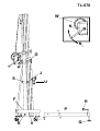
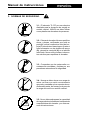
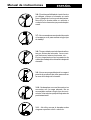
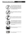
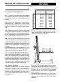
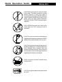
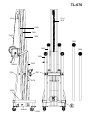
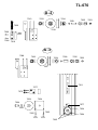
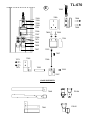
TL-070
E
TORRE ELEVADORA
MANUAL DE INSTRUCCIONES
GB TOWERLIFT
USA
INSTRUCTIONS
Quick Operation Guide
Recycled paper
TORRE ELEVADORA
TOWERLIFT
TRAVERSENLIFT
PIED ÉLÉVATEUR
TL-070
Fabricante - Manufacturer - Hersteller - Fabricant
VMB Española S.A.
Calle 2 - Pol. Ind. Picassent
E-46220 Picassent
TL-070
W
N1
N2
O
J
S
U
F
H
P
T
R
V
Q
Manual de instrucciones
1.
ESPAÑOL
CONTENIDO
2.4 - Carga mínima elevable : 50 Kg.
1. Introducción
2. Datos técnicos
3. Normas de seguridad
4. Instrucciones de uso
5. Mantenimiento
6. Resolución de problemas
2.5 - Altura máxima : 6,40 m.
INTRODUCCION
Estimado usuario,
Lea atentamente este manual.
Observe los datos técnicos y siga las normas
de seguridad antes de utilizar la torre elevadora.
Los elevadores VMB son sometidos a
durísimas pruebas para garantizar la máxima
fiabilidad y resistencia. La torre TL-070 está
especialmente concebida para trabajar con
total fiabilidad y seguridad. Su mecanismo de
elevación incorpora el sistema de seguridad
ALS «auto-lock safety» exclusivo de VMB.
Este manual deberá estar disponible
permanentemente junto a la torre elevadora.
En caso de necesitar piezas de repuesto,
diríjase a su distribuidor habitual. Solamente
deben utilizarse piezas de repuesto originales. El usuario perderá todos sus derechos
de garantía si incorpora cualquier repuesto
que no sea original o realiza cualquier modificación en la torre.
Para cualquier consulta sobre la torre deberá
indicar el número de serie y año de construcción.
2. DATOS TECNICOS
2.1 - Torre elevadora modelo TL-070
2.2 - Diseñada para levantar cargas en
sentido vertical a diferentes alturas.
2.3 - Carga máxima elevable : 250 Kg.
2.6 - Altura mínima : 2,20 m.
2.7 - Superficie de la base : 1,99 x 1,99 m.
2.8 - Peso de transporte : 113 Kg.
2.9 - Material de construcción : Cuerpo principal en perfil de aluminio extrusionado 6082T6. Base y patas en perfil de acero según DIN
2394. Gatillos y cremallera de seguridad en
acero ST-37.
2.10 - Sistema deslizante sobre patines de
nylon de 4 tramos accionado por una combinación de cable de acero en doble sirga y
cadenas, todo ello guiado por poleas acanaladas con cojinetes de rodamiento a bolas.
Sistema exclusivo VMB (mod. ut. pen.
200202230)
2.11 - Cabrestante : 900/1000 Kg. de carga
máxima con freno automático de retención de
la carga. Certificación CE y GS VBG 8.
2.12 - Cable : Acero según DIN 3060. Calidad
180 Kg/mm2 resistente a la torsión. Diámetro
6 mm.
2.13 - Cadenas de suspensión de mallas
juntas 4x4 de 1/2'' capacidad máxima 3.600
Kgs.
2.14 - Platillos estabilizadores ajustables en
las patas, con apoyos antideslizantes de
caucho.
2.15 - Anclaje de las patas por gatillos de
seguridad.
2.16 - Nivel de burbuja para ajustar la posición
vertical de la torre.
2.17 - Protección antióxido y acabado por
cadmiado electrolítico.
2.18 - Ruedas direccionables para facilitar
el transporte de la torre en posición vertical
y plegada hasta su emplazamiento de
trabajo.
Manual de instrucciones
3. NORMAS DE SEGURIDAD.
ESPAÑOL
!
3.1 - El elevador TL-070 es una máquina
diseñada para la elevación de cargas en
sentido vertical, NUNCA se debe utilizar
como plataforma elevadora de personas.
3.2 - Colocar el elevador sólo en superficies
duras y planas, verificando que está en
posición vertical, mediante el nivel de burbuja (F) situado en el tramo base. Ajustar si
fuera necesario con los platillos de apoyo
(Q), girando la manivela (H) en el sentido
adecuado. Nunca utilice cuñas ni elementos extraños para equilibrar el elevador.
3.3 - Comprobar que las patas están correctamente montadas y sujetas por sus
pasadores retenedores de seguridad.
3.4 - Nunca se debe elevar una carga sin
antes verificar que está correctamente
apoyada y centrada en los soportes elevadores adecuados, de forma que el peso de
la carga sólo actúe en sentido vertical.
K gs
3.5 - No se debe sobrepasar la capacidad
de carga máxima indicada en la etiqueta de
características del elevador y en este manual de instrucciones.
Manual de instrucciones
ESPAÑOL
3.6 - Si existe posibilidad de viento fuerte o
en ráfagas, coloque el elevador en suelo
firme y asegúrelo con la ayuda de tirantes.
Nunca fije un tirante sobre un vehículo o
cualquier otro elemento que pueda desplazarse.
3.7 - No use escaleras encima del elevador
ni las apoye en él para realizar ningún tipo
de trabajo.
3.8 - Tenga cuidado con todo tipo de salientes por encima del elevador como cornisas, balcones, letreros luminosos, etc...
Es muy importante evitar la presencia de
cables por debajo de la altura de trabajo del
elevador.
3.9 - Nunca se ponga debajo de la carga ni
permita la presencia de otras personas en
la zona de trabajo del elevador.
3.10 - No desplace nunca el elevador si se
encuentra con la carga elevada. No es
aconsejable realizar ningún tipo de movimiento, ni tan siquiera pequeños ajustes de
posicionamiento.
3.11 - No utilice nunca el elevador sobre
ninguna superficie móvil o vehículo.
Manual de instrucciones
ESPAÑOL
3.12 - Antes de utilizar el elevador, verifique el estado del cable. El cable no debe
presentar rotura de hilos o aplastamiento.
NUNCA use cables defectuosos y en caso
de duda cambie el cable. Sólo utilice cable
de acero según DIN 3060. Calidad 180 Kg/
mm2 resistente a la torsión.
3.13 - Nunca desmonte la manivela del
cabrestante si el elevador está con carga y
elevado.
-50
3.14 - La carga mínima para un funcionamiento del freno sin problemas es de 50 Kg.
Sin esta carga mínima el freno no actuará.
3.15 - No engrase ni lubrique el mecanismo
de freno del cabrestante. Los discos de
freno, han sido engrasados con una grasa
especial resistente al calor y la presión. No
deben ser utilizados otros productos para
evitar influir negativamente en el funcionamiento del freno.
3.16 - Para el transporte del elevador hay
que bajar todos los tramos.
3.17 - Solamente deben utilizarse piezas
de repuesto originales.
ORIGINAL
Manual de instrucciones
ESPAÑOL
Distancia del centro
de la carga a la torre
4. Instrucciones de uso.
4.1 - Coloque la torre elevadora apoyada en
sus ruedas de transporte (T) sobre una superficie plana y firme en su emplazamiento de
trabajo.
4.2 - Saque las patas de su soporte para
transporte (S) e insértelas a fondo en sus
alojamientos de trabajo (V) comprobando que
quedan sujetas por los gatillos retenedores
(R).
4.3 - Ajuste la posición vertical de la torre
mediante los platillos de apoyo regulables (Q)
girando las manivelas de las patas estabilizadoras para lograr que la burbuja del indicador
de nivel (F) quede centrada en el círculo.
A
B
C
D
E
F
G
H
I
25 cm
30 cm
40 cm
50 cm
60 cm
70 cm
80 cm
90 cm
100 cm
Carga máxima
elevable
250 kg
208 kg
156 kg
125 kg
104 kg
89 kg
78 kg
69 kg
62 kg
Para montajes con el kit de elevación VMB
BS-070, o brazos de carga similares, la capacidad máxima de la torre depende de la distancia de carga en el soporte.
4.4 - Coloque los brazos de carga en posición
horizontal y fíjelos con los pasadores de seguridad. También puede elevar todo tipo de
cargas sueltas (nunca puentes) usando directamente las abrazaderas alicraft del carro
elevador.
VMB aconseja los kit de elevación SU-070 y
BS-070, especialmente diseñados para la
elevación de cargas con la torre TL-070.
4.5 - LA CARGA MÁXIMA ES DE 250 Kg.
Nunca debe sobrecargarse la torre por encima de su carga máxima de trabajo (250 kg).
La seguridad de trabajo es lo más importante.
Coloque la carga sobre la torre mediante un
soporte adecuado según el caso, de forma
que el peso de la carga sólo actúe en sentido
vertical. La carga mínima es de 50 Kg.
4.6 - Colocar la carga
Cuando utilice brazos de carga coloque
SIEMPRE la carga lo más cerca posible de la
torre. La carga máxima de la torre TL-070
disminuye con la distancia al cuerpo de la
torre. Véase cuadro de cargas en función de
la distancia.
El Kit SU-070 está preparado para la carga
frontal de trusses de sección triangular o
rectangular de todas las dimensiones desde
25 cm a 52 cm. El Kit BS-070 de brazos
puede utilizarse tanto para la carga lateral
como frontal.
La carga máxima elevable con estos brazos es de 250 kg cuando el centro de la
carga se sitúa a menos de 25 cm del carro
elevador.
Manual de instrucciones
Cargar un puente
Para elevar un puente de manera LATERAL
puede colocarlo apoyado sobre el kit de brazos BS-070. Cuando trabaja con UNA sola
torre también puede apoyarlo sobre las abrazaderas del carro. NUNCA utilice las abrazaderas para elevar con varias torres.
Para cargar puentes de manera frontal utilice
el Kit de brazos cortos SU-070. Este kit permite cargar todo tipo de trusses de sección
triangular o rectangular entre 25 y 52 cm. Con
el Kit de brazos largos BS-070 también pueden cargar trusses frontalmente.
Cargar estructuras
Para elevar puentes y sistemas estructurales
con varias torres a la vez, utilice siempre el Kit
de brazos largos BS-070 apoyando la estructura sobre dichos brazos de forma que esta no
quede fijada rígidamente.
NUNCA cargue las estructuras directamente
sobre las abrazaderas alicraft del carro cuando la carga deba ser elevada por varias torres
enfrentadas y de manera simultánea.
MUY IMPORTANTE: Cuando se utilizan dos
torres para elevar un puente, o varias torres
para elevar una estructura rectangular o de
cualquier otra forma, es muy dificil que varias
personas accionen los cabrestantes y eleven
o bajen las torres exactamente por igual. En
un momento determinado cada torre puede
estar situada a una altura muy diferente de
las demás.
Es necesario que las sujeciones de la estructura permitan las holguras y articulaciones necesarias para absorber las diferencias entre
la altura de cada torre. Con una fijación rígida, si la diferencia de nivel es importante, la
fuerza del brazo de palanca generado forzará lateralmente las torres pudiendo llegar a
frenarlas y bloquearlas. Además puede llegar
a deformar la propia estructura de truss.
ESPAÑOL
Sistema de seguridad ALS
La torre TL-070 dispone del sistema de seguridad ALS autolock security (gatillo rojo).
ALS es un mecanismo de seguridad patentado y exclusivo de VMB. El sistema ALS bloquea automáticamente la torre en cualquier
posición que se deje. Cada tramo de cadena
incorpora además un sistema de seguridad
ALS (automatic lock security) que bloquea el
tramo en el caso poco probable de rotura de
la cadena.
4.7 - Elevar:
No elevar la torre sin una carga mínima de 50
kg. Para elevar quite el bloqueo (O) y gire la
manivela del cabrestante. La carga se elevará hasta la altura deseada.
En caso de subir la torre sin carga o con una
carga inferior a 50 kg, los sistemas de seguridad bloquearán la torre automáticamente a la
altura elevada y no podrá bajarse. Podría llegar a bajar el tramo del cable dejando las cadenas sueltas. La torre quedará bloqueada y
para poder bajarla será necesario colgar del
carro elevador una carga superior a 50 kg.
Entonces habrá que subir de nuevo la torre
hasta tensar cable y cadenas, para liberar los
sistemas de seguridad. Una vez tensado el
cable y las cadenas se podrá bajar normalmente, manteniendo desenclavado el gatillo rojo
ALS AutoLock.
4.8 - Aguantar:
Suelte la manivela del cabrestante y la torre se
mantendrá en esa posición por la actuación
del freno automático accionado por la carga.
La torre puede dejarse en cualquier posición
intermedia que se necesite, soltando simplemente la manivela.
4.9 - Descenso:
Para bajar la torre levante el gatillo rojo de
seguridad y manteniéndolo levantado, gire la
manivela del cabrestante. La carga irá descendiendo con los diferentes t r a m o s h a s t a q u e l a t o r r e q u e d e completamente
plegada a su altura mínima.
Manual de instrucciones
La torre puede dejarse en cualquier posición
intermedia que se necesite del mismo modo
que al subir la carga.
En caso de que el gatillo esté bloqueado por
la carga, hay que subir ligeramente la torre
girando la manivela del cabrestante para después, una vez liberado el gatillo, ir bajando con
normalidad.
4.10 - Transporte:
Pliegue la torre bajando completamente los
tramos. Una vez plegada fije el carro elevador
con el soporte (O). Desmonte las patas
liberando los gatillos de retención y colóquelas en su posición de transporte (S).
Apriete los tornillos (J).
ESPAÑOL
5.3 - La torre elevadora TL-070 debe ser
comprobada por un experto como mínimo una
vez al año de acuerdo con su utilización.
5.4 - Solamente deben utilizarse piezas de
repuesto originales para garantizar una
continuada seguridad de uso.
El usuario pierde todos los derechos de garantía si incorpora otros repuestos que no
sean originales o lleva a cabo cualquier
modificación en el aparato.
5.5 - Para solicitar cualquier pieza de repuesto,
debe indicarse su número de referencia, que
figura en las hojas de despiece de este
manual.
5. Mantenimiento.
6. Resolución de problemas.
5.1 - Compruebe periódicamente el estado
del cable. Si un cable presenta rotura de hilos
o aplastamiento, debe ser substituido inmediatamente por otro nuevo. No utilice la torre
con cables en mal estado. Utilice solamente
cable de acero DIN 3060 resistente a la torsión.
-Si la torre va muy dura...
5.2 - La torre elevadora se suministra completamente engrasada de fábrica. No obstante,
se recomienda engrasar periódicamente
(según el uso) la corona dentada del
cabrestante, los cojinetes del árbol de accionamiento y el buje, la rosca de la manivela y los tramos.
ATENCION: No engrasar ni lubricar el mecanismo del freno.
No es necesario engrasar los discos de freno.
Los discos de freno han sido engrasados con
una grasa especial resistente al calor y la
presión. No deben ser utilizados otros productos para evitar influir negativamente en el
funcionamiento del freno.
Compruebe si la carga total excede los 250
Kg. No sobrepase esta carga máxima.
Compruebe que la carga esté colocada correctamente. Consulte el cuadro de cargas y
distancias del punto 4 de este manual. La
carga no debe estar demasiado separada (excesiva distancia) del cuerpo de la torre. Coloque la carga correctamente y siempre lo más
cerca posible del cuerpo de la torre.
En caso de trabajar con varias torres, compruebe que las torres estén elevadas a la misma altura. Si las alturas son diferentes, las
torres están realizando una fuerza lateral que
provoca su frenado. Iguale siempre las alturas y suba de forma nivelada.
Compruebe que las fijaciones de la estructura
a elevar no sean rígidas permitiendo las holguras necesarias para una elevación manual.
Coloque siempre una fijación de forma que
permita ligeros desplazamientos del apoyo.
Utilice los Kits de carga SU-070 y BS-070.
Manual de instrucciones
-Si la torre no baja
Puede ser debido a que la torre se ha elevado sin carga o con una carga inferior a 50 Kg.
Coloque en el carro elevador (ref.7056) una
carga superior a 50 Kg. Eleve de nuevo la
torre para tensar las cadenas y liberar el sistema de seguridad. Después gire la manivela
del cabrestante y haga descender la torre con
normalidad, manteniendo levantado el gatillo
rojo ALS.
Si está utilizando varias torres, para elevar
un puente o estructura, puede que al tratar
de bajar la estructura las torres queden bloqueadas. Esto es debido a que la acción manual para bajar varias torres no es exactamente la misma y pueden haber diferencias
de altura entre el conjunto de torres. Compruebe las sujeciones de la torre a la estructura. Si trabaja con sujeciones rígidas para
cargar las estructuras a la torre, esa rigidez
impide la absorción de las diferencias de altura entre las torres y estas pueden quedar
frenadas debido al esfuerzo lateral de palanca, lo cual activa el sistema de seguridad ALS
de los tramos bloqueando la torre.
Primero suba las torres que estén más bajas
hasta la misma altura que las demás. Después vuelva a elevar todas las torres por igual
unos 10 cm, hasta tensar las cadenas y liberar los sistemas de seguridad ALS de los tramos de cadena. De esta manera desbloqueará las torres. Para finalizar, baje todas las
torres a la vez, de forma que el conjunto esté
lo más nivelado posible.
Cambie inmediatamente la forma de sujeción.
Siempre que trabaje con varias torres deje un
mínimo de juego en las sujeciones para absorver las diferencias de altura durante la elevación y el descenso.
VMB recomienda los soportes PS-04 y
PS-05 con sujeción tipo U.
ESPAÑOL
TORRE ELEVADORA
TL-070
PRODUCTO FABRICADO POR:
VMB Española S.A.
Calle 2 - Pol. Ind. Picassent
E-46220 Picassent
Declaración de conformidad CE según la norma de la CE sobre
máquinas 89/392/CE
Declaramos que las torres VMB
-modelo TL-070
corresponden, con un uso correcto para la elevación y descenso de cargas, a las
disposiciones de la normativa de máquina 89/392/CE, las demás normativas CE y
ampliaciones correspondientes.
La torre elevadora TL-070 ha sido probada según la norma
BGV C1 (GUV 6.15) / BGG 912 (GUV 66.15)
obteniendo la certificación de prueba con fecha 08/07/02
Las pruebas han sido realizadas por
IBB ingenieure sachverständige
Dipl. - Ing. univ. Olaf Brandt
Nollendorfstrasse 18
D-45472 Mülheim an der Ruhr
La torre TL-070 suministrada corresponde a la muestra verificada.
Quick Operation Guide
CONTENTS
1.
2.
3.
4.
5.
6.
Introduction.
Technical information.
How to place the load
How to load structures
How to load a bridge
Trouble shooting
ENGLISH
2.3 - Maximum load : 550 lbs / 250 Kg.
2.4 - Minimum load : 110 lbs / 50 Kg.
2.5 - Maximum height : 21 ft / 6,4 m.
2.6 - Minimum height : 7.2 ft / 2,2 m.
2.7 - Area of base : 6.5x6.5 ft / 1,99x1,99 m.
2.8 - Unit weight : 248.6 lb / 113 Kg.
1.
INTRODUCTION
Dear customer,
In order to operate the towerlift TL-070 in
a safe and reliable manner, follow the
instructions in this booklet.
Before operating the lift, read the instructions
carefully.
Please note the technical information.
Our products undergo very rigorous testing
under strict conditions and they are monitored
continuously during the manufacturing
process.
2.9 - Construction material : Main body in
extruded aluminium 6082-T6 profile. Base and
legs are made of steel profile according to DIN
2394. Catches and safety rack of ST-37 steel.
2.10 - Exclusive system (mod. ut. pen.
200202230)
2.11 - Winch : 900/1000 Kg. of maximum load
with automatic brake to stop the load.
2.12 - Cable : Steel DIN 3060. Quality 180 Kg/
mm2 twist resistant. Cable diameter : 6 mm.
2.13 - Chains 4x4 of 1/2'' maximum capacity of
3.600 Kgs.
In order to guarantee the lift function and
safety, the original parts of the manufacturer's
design must be used. If any parts other than
those of the manufacturer are used, or the
product is modified in any way, the user
forfeits all warranty rights to claim.
2.14 - Adjustable stabilizing feet with ruber
non-slip supports.
VMB reserves the right to modify the
product specifications without prior notice.
The model type, production year and
serial number must be quoted in any
queries or orders for spare parts.
2.17 - Antirust protection and cadmium plating.
2. TECHNICAL INFORMATION
2.1 - Towerlift TL-070.
2.2 - Designed to lift loads vertically to
different heights to support lighting systems.
2.15 - Safety catches to anchor the legs.
2.16 - Spirit level to adjust the tower vertically.
2.18 - Swivel wheels to transport the lift when
folded.
Quick Operation Guide
3. SAFETY PRECAUTIONS.
ENGLISH
!
3.1 - The TL-070 is a machine designed to
elevate loads upwards in a vertical direction,
NEVER should it be used as a platform to
elevate people.
3.2 - Only place the lift on hard, flat surfaces
always checking that it is in a vertical position
by using the bubble level indicator (F) found
on the base section. Adjust the outrigger
stabilisers (Q) by turning the cranks to level
if necessary. NEVER use wedges or other
foreign objects to bring the lift to equilibrium.
3.3 - Check that the outriggers are placed
and set-up correctly using the pins safety
system.
3.4 - NEVER should the lift be used to
elevate a load that has not been properly
checked. It is necessary to verify that the
load is correctly supported and centred on
the appropriate lift support so that the weight
of the load will only elevate in a vertical
direction.
K gs
3.5 - The maximum load indicated on the
characteristics label and the instructions
manual should not be exceeded
Quick Operation Guide
ENGLISH
3.6 - If there is a possibility of strong winds
or gusts, place the lift on the ground firmly
and secure it with the use of straps. NEVER
attach a strap to a vehicle or any other
object that can possibly be moved.
3.7 - Do not use stepladders on the lift or
use it as a support for them.
3.8 - Take care with all obstacles above the
lift and its extension zone such as cornices,
balconies, and luminous signboards. It is
very important to avoid the presence of all
types of cables below the extended lift.
3.9 - NEVER allow any team member below
the load or anybody else in the lifts operating
zone.
3.10 - NEVER move the lift whilst it is
carrying a load. It is not advisable to carry
out any type of movement even small
positional adjustments.
3.11 - NEVER use the lift on a vehicle or any
other mobile surface.
Quick Operation Guide
ENGLISH
3.12 - Before using the lift, check the state
of the cable. The cable should not contain
broken threads or show any signs of
crushed/flattened areas. NEVER use faulty
cables, always change them if there is any
doubt. Only use steel cables reference:
DIN 3060. Quality: 180KG/mm and torsion
resistant.
3.13 - NEVER take apart the crank of the
winch when the lift is carrying a load or
extended.
-50
3.14 - The minimum load to avoid problems
regarding the breaking mechanism is 50KG.
Without this load the brake will not work.
3.15 - Do not grease or lubricate the winch’s
breaking mechanism. The brake disks have
been greased with a special heat and
pressure resistant solution. Other products
should not be used to avoid negative effects
regarding the braking mechanism.
3.16 - All sections must be lowered during
transportation.
3.17 - Only original replacement parts should
be used.
ORIGINAL
Quick Operation Guide
ENGLISH
Load centre’s
DISTANCE
to the lifting carriage
4. USAGE INSTRUCTIONS.
4.1 - Place the lift on a firm, flat surface in the
area it is to be used supported its transport
wheels (T).
4.2 - Remove the outriggers from their transport
supports (S) and fully insert them into their
positions (V) checking that they are fixed by
the pins (R).
A
B
C
D
E
F
G
H
I
10 ‘‘ - 25 cm
12 ‘‘ - 30 cm
16 ‘‘ - 40 cm
20 ‘‘ - 50 cm
24 ‘‘ - 60 cm
28 ‘‘ - 70 cm
32 ‘‘ - 80 cm
36 ‘‘ - 90 cm
40 ‘‘ -100 cm
Maximum lifting
LOAD
550 lb - 250 kg
457 lb - 208 kg
343 lb - 156 kg
275 lb - 125 kg
229 lb - 104 kg
196 lb - 89 kg
171 lb - 78 kg
152 lb - 69 kg
136 lb - 62 kg
4.3 - Adjust the outrigger stabilisers (Q) by
turning the cranks to level the lift. Ensure it is
in a vertical position by using the bubble level
indicator (F) found on the base section. The
bubble should be in the centre of the circle.
4.4 - Place the forklifts in a horizontal position
and secure them with the pins.
VMB recommends the SU-070 Elevation Kit
and the BS-070 Elevation Kit which have both
been especially designed for loading and
elevating with the TL-070.
4.5 - THE MAXIMUM LOAD IS 250KG. The
lift should NEVER be overloaded (over 250KG).
Safety at work is the most important element.
Place the load onto the lift using an adequate
support according to the need, use so that the
weight of the load will only elevate in a vertical
direction. The minimum load is 50KG
4.6 - How to place the load
Always load as close to the tower as possible. The maximum load diminishes according
to the distance from the body of the tower as
illustrated in the diagram below.
The maximum load is 250 kg when the
load’s centre is at 25 cm from the lifting
carriage of the towerlift.
VMB recommend the use of the VMB special
support kits SU-070 and BS-070. The SU-070
Kit is prepared for frontal loading of triangular
or rectangular trusses of all the dimensions
from 25 cm to 52 cm. The BS-070 Kit can be
used for frontal or lateral loading.
How to load a bridge
To lift a bridge you can use the VMB kits SU070 and BS-070. To load bridges of both triangular and rectangular trusses measuring between 25 and 52 cm, the SU-070 Kit can be
used for frontal mountings. BS-070 can be
used for frontal or lateral loading. NEVER use
the half couplers alicraft to lift a bridge.
Quick Operation Guide
ENGLISH
How to load structures
To elevate structures it is necessary to use
the BS-070 Kit. The arms support the structure but not in a rigid position.
Security system ALS
The TL-070 incorporates the patented security
system ALS (Automatic Lock Security).
This VMB red trigger system automatically
blocks the tower in the position it is left in.
Each section of chain has an ALS that blocks
the section in the unlikely event of the chain
breaking.
DO NOT LOAD STRUCTURES DIRECTLY
ONTO THE ALUMINUM HALF COUPLERS
ON THE TROLLEY
CAUTION
When two towers are used to elevate a bridge
or many towers to elevate a structure of any
type, it is almost impossible that two or more
people co-ordinate the winches elevating or
lowering the loads, at exactly the same pace.
At a certain point each tower will be extended
to a height different to that of the others.
For this reason it is necessary that the
subjections of the structure account for this
and allow for these differences. With a rigid
fixation and if the level difference is significant, the force generated from the handle of
the winch will deform the structure and apply
a lateral force to the lifts causing them to break
and block.
4.7 - Lift:
DO NOT ELEVATE THE LIFT WITHOUT A
MINIMUM LOAD OF 50kg
Elevating the lift without any minimum load will
cause the ALS to block the lift while extended
and it will not descend, it may even lower the
section of the cable leaving the chains loose.
The lift will remain blocked but to release and
lower it, it is necessary to apply the minimum
load of 55 lb (25kg). Then the lift needs to be
raised so as to tighten the cable and chains
to free the security systems. When the cable
and chains have been tightened it is possible
to lower the lift normally, of course making sure
the red ALS latch is held up.
4.8 - Hold:
The tower can be left in any intermediate
position which would be necessary. Just stop
turning the handle of the winch and left it. The
automatic brake of the winch will block it and
hold the load.
4.9 - Lowering:
To low the load lift the blockade on the red
safety trigger and rotate the handle of the
winch
until the tower will be completely folded at his
minimal height. The load will be lowed.
4.10 - Transport:
For the transport of the tower is necessary to
fold the machine lowering completely all the
profiles. Once the towerlift is folded it is very
important to blockade the lifting carriage with
its transport support (O). Get out the legs
leaving the blockade on the triggers and put
them in their transport lodging (S). Then press
the fastening screws.
Quick Operation Guide
ENGLISH
5. MAINTENANCE.
6. TROUBLE SHOOTING
5.1 - Regularly check the state of the cable. If
the cable has broken threads, or if it shows any
signs of crushed/flattened areas, it should be
changed and replaced immediately by a new
one. Do not use the lift if the cables are in bad
condition. Only use steel cables reference:
DIN 3060 torsion resistant.
- HARD TO ELEVATE:
5.2 - The lift is supplied from the factory
completely greased. However, it is
recommended to periodically grease according
to use, the gearing, the axis bearings, the
spiral of the crank, and the sections.
REMEMBER: NEVER grease or lubricate
the breaking mechanism.
It is not necessary to grease the brake
disks. The brake disks have been greased
with a special heat and pressure resistant
solution. Other products should not be used
to avoid negative effects regarding the braking mechanism.
5.3 - An expert should check the TL-070 at
least once a year according to its usage.
Consult your distributor.
5.4 - Only original replacement parts should be
used to guarantee continued safety during
usage.
The user loses all guarantee rights if he/she
uses replacement parts that are not original
or if he/she makes any modification to the
apparatus.
5.5 - To order any replacement parts, the
reference number on the replacement parts
pages in this manual should be indicated.
Check that the total load does not exceed 550
lb (250 kg) DO NOT TO EXCEED THE MAXIMUM LOAD.
Check that the load is not placed excessively
from the body of the tower according to diagram in this quick operation guide.
ALWAYS LOAD AS CLOSE TO THE LIFT AS
POSSIBLE.
Check that the lifts in use when elevating a
bridge or truss structure are at equal heights
and not causing force laterally causing them
to brake. If this is the case adjust the heights
and continue to elevate the load in a horizontal position. Check that the fixations of the
bridge or structure are not rigid whilst elevating and that they allow for the necessary
movements during elevation. Place the fixation so that it allows for slight displacements
of the support. Use the loading kits SU-070 &
BS-070.
-DIFFICULTY IN LOWERING THE LIFT
WHEN EXTENDED.
As explained above, it is necessary to apply
the minimum load of 110 lb (50kg). If this is
not the case and the lift does not descend,
carry out the following:
A. Extend the lift to tighten the cable and
chains to free the security system.
B. When the cable and chains have been
tightened it is possible to lower the lift
normally
C. Make sure the red ALS latch is held up.
Quick Operation Guide
Check that the fixations of the bridge or structure are not rigid whilst elevating and that they
allow for the necessary movements during elevation. The security system will have blocked
the towers automatically. Change the subjection carry out the instructions indicated below
.
Firstly elevate the lifts that are lower, to the
same height as the others.
Elevate the lifts simultaneously about 10 centimetres tightening the chains and releasing
the ALS security systems on the chain sections unlocking the lifts
Lower the lifts simultaneously with the load in
a horizontal position.
VMB recommends the PS-04 and PS-05
supports with fixation pieces type U.
-WHEN THE LIFT IS BLOCKED
When working with several towerlifts, firstly
elevate the lifts that are lower, to the same
height as the others.
Elevate the lifts simultaneously about 10 centimetres tightening the chains and releasing
the ALS security systems on the chain sections unlocking the lifts
Lower the lifts simultaneously with the load in
a horizontal position.
ENGLISH
TOWERLIFT
TL-070
PRODUCT MANUFACTURED BY:
VMB Española S.A.
Calle 2 - Pol. Ind. Picassent
E-46220 Picassent
EC Conformity Declaration pursuant to the EC Machinery Directive
89/392 EEC
We hereby declare that VMB towerlifts
-model TL-070
satisfy the EC Machinery Directive 89/392 EEC regulations, relevant EC directives
and amendments when used for lifting and lowering loads as directed
TL-070 towerlifts have been tested corresponding the regulations
BGV C1 (GUV 6.15) / BGG 912 (GUV 66.15)
obteining the Test Certification on 14/03/97
Examining and Certification have been made by
IBB ingenieure sachverständige
Dipl. - Ing. univ. Olaf Brandt
Nollendorfstrasse 18
D-45472 Mülheim an der Ruhr
The towerlift TL-070 supplied conform to the tested types.
TL-070
A
D
B
C
7056
TL-070
7013
7011
ALS
7050
7051
7043
7052
7055
7055
7054
7054
7053
7502-G
7503
7057
2170
2034
E
2026-B
7056
TL-070
A -3
7052
A
7020
A-2
7051
7011
7013
7069
7069
A -1
7068
7075
7073
7050
7013
7074
7070
7043
7068
7070
A-1
7046
7022
7035
7006
7035
7023
7047
7020
7049
7004
7005
7069
7047
7036
7069
7019
7045
7069
7069
TL-070
A -2
7010
7033
7034
7009
7035
7020
7018
7069
7022
7069
7019
A -3
7008
7033
7034
7009
7035
7023
7007
7011
7077
7070
7004
7024
7064
7077
7066
7024
7065
7065
7004
7076
7076
7065
7023
TL-070
B
C
7057
7042
7062
7538
7537
7539
7042
7537
7059
7538
7061
7058
7539
7061
7060
7060
D
2037
2029
2161
2037
2050
2051
2029
2051
2050
2161
7067
7048
7015
2051
2046
7048
2047
2048
7015
2049
2030
2047
2030
2048
2049
TL-070
E
7020
7029
7069
7029
7032
7069
7031
7069
7032
7038
7069
7069
7069
7037
7028
7031
7071
7025
7026
7027
7072
7037
7071
7071
7025
7028
7026
7023
7027
LOAD SUPPORTS
7040
7041
PS-04
PS-05
LISTA DE PIEZAS TL-070 / SPARE PARTS LIST
Ref.
Descripción / Description :
2026-C
2029
2030
2034
2037
2046
2047
2048
2049
2050
2051
2161
2170
7001
7002
7003
7004
7005
7006
7007
7008
7009
7010
7011
7013
7015
7018
7019
7020
7022
7023
7024
7025
7026
7027
7028
7029
7031
7032
7033
7034
7035
7036
7037
7040
7041
Gatillo seguridad / Safety catch.
Pomo baquelita / Crank nob.
Platillo de apoyo / Stabilizer round plate.
Nivel de burbuja / Bubble level.
Tornillo M8 / M-8 screw.
Tuerca M5 / M-5 nut.
Arandela / Washer.
Arandela / Washer.
Tornillo M6 / M-6 screw.
Tornillo M5 / M-5 screw.
Tuerca M8 / M-8 washer.
Manivela patas / Steel hand crank.
Pomo con rosca M8 / M-8 cranck nob.
Patín tetones / Centrator sliding profile.
Patín U / U Centrator sliding profile.
Patín L / L Centrator sliding profile.
Polea cable / Ball bearing cable pulley.
Soporte polea / Pulley 7004 and ALS trigger support.
Bulón acero / Pulley 7004 steel axe.
Polea cadena / Ball bearing chain pulley.
Soporte cadena / Chain 7020 support.
Bulón acero / Pulley 7018 steel axe.
Soporte polea / Chain pulley 7018 support.
Corredera ALS / ALS track.
Gatillo ALS / ALS trigger.
Tapón pata / Leg stabilizer guide.
Polea cadena / Ball bearing chain pulley.
Fijación cadena / Chain 7020 fixation.
Cadena tracción/ Chain AL-444.
Eje acero / Chain 7020 steel axe.
Arandela de presión / Pressure washer.
Pletina acero / Cable 7004 internal pulley support plate.
Sujeción mecanismo del freno / Brake mechanism fixation piece.
Eje de acero / Safety steel axe.
Gatillo de bloqueo / Trigger.
Varilla roscada M5 / Special stick.
Pletina de acero / Support steel plate.
Pieza sujeción varilla / Fixation special stick piece.
Pieza fijación cadena / Chain 7020 fixation piece.
Arandela centrador pequeña / Special small washer.
Arandela centrador grande / Special big washer.
Arandela / Washer.
Placa refuerzo gatillo ALS 7013 / ALS 7013 reinforcement plate.
Muelle / Spring.
Brazo de carga largo / Load support long fork.
Brazo de carga corto / Load support short fork.
LISTA DE PIEZAS TL-070 / SPARE PARTS LIST
Ref.
Descripción / Description :
7042
7043
7045
7046
7047
7048
7049
7050
7051
7052
7053
7054
7055
7056
7057
7058
7060
7061
7064
7065
7066
7067
7068
7070
7072
7073
7074
7075
7076
7077
7078
7079
7080
7081
7082
7083
7084
7085
7086
7087
7088
7089
7502-G
7503
7537
7538
7539
7645
Pieza bloqueo transporte / Lock piece for transport.
Cable acero / Steel cable.
Pletina de acero / Steel plate.
Pieza de refuerzo / Reinforcement piece.
Tornillo M8 / M-8 screw.
Perno roscado M-18 / M-18 screw.
Tornillo M-8 / M-8 screw.
Tramo 1 / Profile section 1.
Tramo 2 / Profile section 2.
Tramo 3 / Profile section 3.
Tramo 4 / Profile section 4.
Pata corta completa / Complete short legs stabiliser.
Pata larga completa / Complete long legs stabiliser.
Ruedas tramo base / Base wheels.
Carro elevador / Lifting carriage.
Perno roscado M-10 / M-10 screw.
Tuerca M-10 / M-10 nut.
Arandela M-10 / M-10 washer.
Tornillo M-12 / M-12 screw.
Tornillo M-6 / M-6 screw.
Tuerca M-12 / M-12 nut.
Estabilizador completo / Complete stabiliser.
Pieza fijación cable / Cable fixation.
Portacabrestante / Winch fixation
Tornillo M10 / M-10 screw.
Arandela / Spring washer.
Portapatas / outrigger support
Fijación portapatas / outrigger support fixation
Tornillo M8 / M-8 screw.
Arandela / Spring washer.
Tuercas M8 / M-8 nut.
Tornillo M-8 / M-8 screw.
Base / Base profil.
Arandela / Spring washer.
Tornillo 4.8 / 4.8 screw.
Tornillo 4.8 / 4.8 screw.
Pieza soporte / Support piece
Arandela / Spring washer.
Tuerca M-6 / M-6 nut.
Tornillo M-6 / M-6 screw.
Tuerca M-6 / M-6 nut.
Tornillo M-6 / M-6 screw.
Cabrestante / Winch.
Tirantes sujección patas / Base profile strut.
Muelle / Spring.
Arandela / Spring washer.
Pasador acero / Steel pin.
Tornillo M-6 / M-6 screw.
VMB ESPAÑOLA S.A.
Pol. Ind. Picassent - Calle 2, final - 46220 Picassent (VALENCIA) Spain
Tel.: +34 902 34 10 34 - Fax: +34 961 22 11 77
Web:www.vmb.es - E-mail: [email protected]


![Page 1 www.Ludowici.com [**INSERT PIC] LUDOWICI TM Desde](http://vs1.manualzilla.com/store/data/006216944_1-046022ddb0fd4b43a805da73ee2d4dd9-150x150.png)