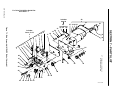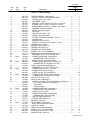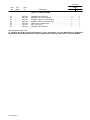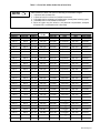
1
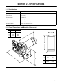
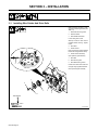
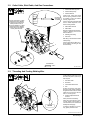
OM-1580C 134 192C May 1996 Processes Automatic Welding Description Wire Feeder A1D-4RV And A1D-4RW Visit our website at www.MillerWelds.com From Miller to You Thank you and congratulations on choosing Miller. Now you can get the job done and get it done right. We know you don’t have time to do it any other way. That’s why when Niels Miller first started building arc welders in 1929, he made sure his products offered long-lasting value and superior quality. Like you, his customers couldn’t afford anything less. Miller products had to be more than the best they could be. They had to be the best you could buy. Today, the people that build and sell Miller products continue the tradition. They’re just as committed to providing equipment and service that meets the high standards of quality and value established in 1929. This Owner’s Manual is designed to help you get the most out of your Miller products. Please take time to read the Safety precautions. They will help you protect yourself against potential hazards on the worksite. We’ve made installation and operation quick and easy. With Miller you can count on years of reliable service with proper maintenance. And if for some reason the unit needs repair, there’s a Troubleshooting section that will help you Miller is the first welding figure out what the problem is. The parts list equipment manufacturer in will then help you to decide which exact part the U.S.A. to be registered to the ISO 9001 Quality System you may need to fix the problem. Warranty and Standard. service information for your particular model are also provided. Miller Electric manufactures a full line of welders and welding related equipment. For information on other quality Miller products, contact your local Miller distributor to receive the latest full line catalog or individual catalog sheets. To locate your nearest distributor or service agency call 1-800-4-A-Miller, or visit us at www.MillerWelds.com on the web. Working as hard as you do – every power source from Miller is backed by the most hassle-free warranty in the business. Miller offers a Technical Manual which provides more detailed service and parts information for your unit. To obtain a Technical Manual, contact your local distributor. Your distributor can also supply you with Welding Process Manuals such as SMAW, GTAW, GMAW, and GMAW-P. TABLE OF CONTENTS SECTION 1 – SAFETY PRECAUTIONS - READ BEFORE USING . . . . . . . . . . . . . . . . . . . . . . . . . . . . 1-1. Symbol Usage . . . . . . . . . . . . . . . . . . . . . . . . . . . . . . . . . . . . . . . . . . . . . . . . . . . . . . . . . . . . . . . . 1-2. Arc Welding Hazards . . . . . . . . . . . . . . . . . . . . . . . . . . . . . . . . . . . . . . . . . . . . . . . . . . . . . . . . . . 1-3. Additional Symbols for Installation, Operation, and Maintenance . . . . . . . . . . . . . . . . . . . . . . 1-4. Principal Safety Standards . . . . . . . . . . . . . . . . . . . . . . . . . . . . . . . . . . . . . . . . . . . . . . . . . . . . . 1-5. EMF Information . . . . . . . . . . . . . . . . . . . . . . . . . . . . . . . . . . . . . . . . . . . . . . . . . . . . . . . . . . . . . . SECTION 2 – SPECIFICATIONS . . . . . . . . . . . . . . . . . . . . . . . . . . . . . . . . . . . . . . . . . . . . . . . . . . . . . . . . . 2-1. Specifications . . . . . . . . . . . . . . . . . . . . . . . . . . . . . . . . . . . . . . . . . . . . . . . . . . . . . . . . . . . . . . . . 2-2. Overall Dimensions And Mounting Hole Layout . . . . . . . . . . . . . . . . . . . . . . . . . . . . . . . . . . . . SECTION 3 – INSTALLATION . . . . . . . . . . . . . . . . . . . . . . . . . . . . . . . . . . . . . . . . . . . . . . . . . . . . . . . . . . . 3-1. Installing Wire Guides And Drive Rolls . . . . . . . . . . . . . . . . . . . . . . . . . . . . . . . . . . . . . . . . . . . . 3-2. Outlet Cable, Weld Cable, And Gas Connections . . . . . . . . . . . . . . . . . . . . . . . . . . . . . . . . . . . 3-3. Threading And Feeding Welding Wire . . . . . . . . . . . . . . . . . . . . . . . . . . . . . . . . . . . . . . . . . . . . SECTION 4 – OPERATION . . . . . . . . . . . . . . . . . . . . . . . . . . . . . . . . . . . . . . . . . . . . . . . . . . . . . . . . . . . . . 4-1. Safety Equipment . . . . . . . . . . . . . . . . . . . . . . . . . . . . . . . . . . . . . . . . . . . . . . . . . . . . . . . . . . . . . 4-2. Sequence Of Operation . . . . . . . . . . . . . . . . . . . . . . . . . . . . . . . . . . . . . . . . . . . . . . . . . . . . . . . . SECTION 5 – MAINTENANCE AND TROUBLESHOOTING . . . . . . . . . . . . . . . . . . . . . . . . . . . . . . . . . 5-1. Routine Maintenance . . . . . . . . . . . . . . . . . . . . . . . . . . . . . . . . . . . . . . . . . . . . . . . . . . . . . . . . . . 5-2. Aligning Drive Rolls And Wire Guides . . . . . . . . . . . . . . . . . . . . . . . . . . . . . . . . . . . . . . . . . . . . 5-3. Brush Inspection And Replacement . . . . . . . . . . . . . . . . . . . . . . . . . . . . . . . . . . . . . . . . . . . . . . 5-4. Troubleshooting . . . . . . . . . . . . . . . . . . . . . . . . . . . . . . . . . . . . . . . . . . . . . . . . . . . . . . . . . . . . . . SECTION 6 – ELECTRICAL DIAGRAMS . . . . . . . . . . . . . . . . . . . . . . . . . . . . . . . . . . . . . . . . . . . . . . . . . SECTION 7 – PARTS LIST . . . . . . . . . . . . . . . . . . . . . . . . . . . . . . . . . . . . . . . . . . . . . . . . . . . . . . . . . . . . . . WARRANTY 1 1 1 3 3 4 5 5 5 6 6 7 7 8 8 8 8 8 9 10 10 11 12 SECTION 1 – SAFETY PRECAUTIONS - READ BEFORE USING som _nd_5/97 1-1. Symbol Usage Means Warning! Watch Out! There are possible hazards with this procedure! The possible hazards are shown in the adjoining symbols. Y Marks a special safety message. . Means “Note”; not safety related. This group of symbols means Warning! Watch Out! possible ELECTRIC SHOCK, MOVING PARTS, and HOT PARTS hazards. Consult symbols and related instructions below for necessary actions to avoid the hazards. 1-2. Arc Welding Hazards Y The symbols shown below are used throughout this manual to call attention to and identify possible hazards. When you see the symbol, watch out, and follow the related instructions to avoid the hazard. The safety information given below is only a summary of the more complete safety information found in the Safety Standards listed in Section 1-4. Read and follow all Safety Standards. D If earth grounding of the workpiece is required, ground it directly with a separate cable – do not use work clamp or work cable. Y Only qualified persons should install, operate, maintain, and repair this unit. D Wear a safety harness if working above floor level. D Keep all panels and covers securely in place. Y During operation, keep everybody, especially children, away. D Clamp work cable with good metal-to-metal contact to workpiece or worktable as near the weld as practical. ELECTRIC SHOCK can kill. Touching live electrical parts can cause fatal shocks or severe burns. The electrode and work circuit is electrically live whenever the output is on. The input power circuit and machine internal circuits are also live when power is on. In semiautomatic or automatic wire welding, the wire, wire reel, drive roll housing, and all metal parts touching the welding wire are electrically live. Incorrectly installed or improperly grounded equipment is a hazard. D Do not touch electrode if you are in contact with the work, ground, or another electrode from a different machine. D Use only well-maintained equipment. Repair or replace damaged parts at once. Maintain unit according to manual. D Insulate work clamp when not connected to workpiece to prevent contact with any metal object. D Do not connect more than one electrode or work cable to any single weld output terminal. SIGNIFICANT DC VOLTAGE exists after removal of input power on inverters. D Turn Off inverter, disconnect input power, and discharge input capacitors according to instructions in Maintenance Section before touching any parts. D Do not touch live electrical parts. D Wear dry, hole-free insulating gloves and body protection. D Insulate yourself from work and ground using dry insulating mats or covers big enough to prevent any physical contact with the work or ground. D Do not use AC output in damp areas, if movement is confined, or if there is a danger of falling. D Use AC output ONLY if required for the welding process. D If AC output is required, use remote output control if present on unit. D Disconnect input power or stop engine before installing or servicing this equipment. Lockout/tagout input power according to OSHA 29 CFR 1910.147 (see Safety Standards). D Properly install and ground this equipment according to its Owner’s Manual and national, state, and local codes. D Keep your head out of the fumes. Do not breathe the fumes. D Always verify the supply ground – check and be sure that input power cord ground wire is properly connected to ground terminal in disconnect box or that cord plug is connected to a properly grounded receptacle outlet. D When making input connections, attach proper grounding conductor first – double-check connections. D Frequently inspect input power cord for damage or bare wiring – replace cord immediately if damaged – bare wiring can kill. D Turn off all equipment when not in use. D Do not use worn, damaged, undersized, or poorly spliced cables. D Do not weld in locations near degreasing, cleaning, or spraying operations. The heat and rays of the arc can react with vapors to form highly toxic and irritating gases. D Do not drape cables over your body. FUMES AND GASES can be hazardous. Welding produces fumes and gases. Breathing these fumes and gases can be hazardous to your health. D If inside, ventilate the area and/or use exhaust at the arc to remove welding fumes and gases. D If ventilation is poor, use an approved air-supplied respirator. D Read the Material Safety Data Sheets (MSDSs) and the manufacturer’s instructions for metals, consumables, coatings, cleaners, and degreasers. D Work in a confined space only if it is well ventilated, or while wearing an air-supplied respirator. Always have a trained watchperson nearby. Welding fumes and gases can displace air and lower the oxygen level causing injury or death. Be sure the breathing air is safe. D Do not weld on coated metals, such as galvanized, lead, or cadmium plated steel, unless the coating is removed from the weld area, the area is well ventilated, and if necessary, while wearing an air-supplied respirator. The coatings and any metals containing these elements can give off toxic fumes if welded. OM-1580 Page 1 ARC RAYS can burn eyes and skin. Arc rays from the welding process produce intense visible and invisible (ultraviolet and infrared) rays that can burn eyes and skin. Sparks fly off from the weld. D Wear a welding helmet fitted with a proper shade of filter to protect your face and eyes when welding or watching (see ANSI Z49.1 and Z87.1 listed in Safety Standards). D Wear approved safety glasses with side shields under your helmet. D Use protective screens or barriers to protect others from flash and glare; warn others not to watch the arc. D Wear protective clothing made from durable, flame-resistant material (leather and wool) and foot protection. BUILDUP OF GAS can injure or kill. D Shut off shielding gas supply when not in use. D Always ventilate confined spaces or use approved air-supplied respirator. HOT PARTS can cause severe burns. D Do not touch hot parts bare handed. D Allow cooling period before working on gun or torch. MAGNETIC FIELDS can affect pacemakers. WELDING can cause fire or explosion. Welding on closed containers, such as tanks, drums, or pipes, can cause them to blow up. Sparks can fly off from the welding arc. The flying sparks, hot workpiece, and hot equipment can cause fires and burns. Accidental contact of electrode to metal objects can cause sparks, explosion, overheating, or fire. Check and be sure the area is safe before doing any welding. D Protect yourself and others from flying sparks and hot metal. D Do not weld where flying sparks can strike flammable material. D Remove all flammables within 35 ft (10.7 m) of the welding arc. If this is not possible, tightly cover them with approved covers. D Be alert that welding sparks and hot materials from welding can easily go through small cracks and openings to adjacent areas. D Watch for fire, and keep a fire extinguisher nearby. D Be aware that welding on a ceiling, floor, bulkhead, or partition can cause fire on the hidden side. D Do not weld on closed containers such as tanks, drums, or pipes, unless they are properly prepared according to AWS F4.1 (see Safety Standards). D Connect work cable to the work as close to the welding area as practical to prevent welding current from traveling long, possibly unknown paths and causing electric shock and fire hazards. D Do not use welder to thaw frozen pipes. D Remove stick electrode from holder or cut off welding wire at contact tip when not in use. D Wear oil-free protective garments such as leather gloves, heavy shirt, cuffless trousers, high shoes, and a cap. D Remove any combustibles, such as a butane lighter or matches, from your person before doing any welding. FLYING METAL can injure eyes. D Welding, chipping, wire brushing, and grinding cause sparks and flying metal. As welds cool, they can throw off slag. D Wear approved safety glasses with side shields even under your welding helmet. OM-1580 Page 2 D Pacemaker wearers keep away. D Wearers should consult their doctor before going near arc welding, gouging, or spot welding operations. NOISE can damage hearing. Noise from some processes or equipment can damage hearing. D Wear approved ear protection if noise level is high. CYLINDERS can explode if damaged. Shielding gas cylinders contain gas under high pressure. If damaged, a cylinder can explode. Since gas cylinders are normally part of the welding process, be sure to treat them carefully. D Protect compressed gas cylinders from excessive heat, mechanical shocks, slag, open flames, sparks, and arcs. D Install cylinders in an upright position by securing to a stationary support or cylinder rack to prevent falling or tipping. D Keep cylinders away from any welding or other electrical circuits. D Never drape a welding torch over a gas cylinder. D Never allow a welding electrode to touch any cylinder. D Never weld on a pressurized cylinder – explosion will result. D Use only correct shielding gas cylinders, regulators, hoses, and fittings designed for the specific application; maintain them and associated parts in good condition. D Turn face away from valve outlet when opening cylinder valve. D Keep protective cap in place over valve except when cylinder is in use or connected for use. D Read and follow instructions on compressed gas cylinders, associated equipment, and CGA publication P-1 listed in Safety Standards. 1-3. Additional Symbols For Installation, Operation, And Maintenance FIRE OR EXPLOSION hazard. MOVING PARTS can cause injury. D Do not install or place unit on, over, or near combustible surfaces. D Do not install unit near flammables. D Do not overload building wiring – be sure power supply system is properly sized, rated, and protected to handle this unit. D Keep away from moving parts such as fans. D Keep all doors, panels, covers, and guards closed and securely in place. FALLING UNIT can cause injury. H.F. RADIATION can cause interference. D Use lifting eye to lift unit only, NOT running gear, gas cylinders, or any other accessories. D Use equipment of adequate capacity to lift and support unit. D If using lift forks to move unit, be sure forks are long enough to extend beyond opposite side of unit. D OVERUSE can cause OVERHEATING D D Allow cooling period; follow rated duty cycle. D Reduce current or reduce duty cycle before starting to weld again. D Do not block or filter airflow to unit. D D D High-frequency (H.F.) can interfere with radio navigation, safety services, computers, and communications equipment. D Have only qualified persons familiar with electronic equipment perform this installation. The user is responsible for having a qualified electrician promptly correct any interference problem resulting from the installation. If notified by the FCC about interference, stop using the equipment at once. Have the installation regularly checked and maintained. Keep high-frequency source doors and panels tightly shut, keep spark gaps at correct setting, and use grounding and shielding to minimize the possibility of interference. STATIC (ESD) can damage PC boards. D Put on grounded wrist strap BEFORE handling boards or parts. D Use proper static-proof bags and boxes to store, move, or ship PC boards. ARC WELDING can cause interference. MOVING PARTS can cause injury. D Keep away from moving parts. D Keep away from pinch points such as drive rolls. D D WELDING WIRE can cause injury. D Do not press gun trigger until instructed to do so. D Do not point gun toward any part of the body, other people, or any metal when threading welding wire. D D D Electromagnetic energy can interfere with sensitive electronic equipment such as computers and computer-driven equipment such as robots. D Be sure all equipment in the welding area is electromagnetically compatible. To reduce possible interference, keep weld cables as short as possible, close together, and down low, such as on the floor. Locate welding operation 100 meters from any sensitive electronic equipment. Be sure this welding machine is installed and grounded according to this manual. If interference still occurs, the user must take extra measures such as moving the welding machine, using shielded cables, using line filters, or shielding the work area. 1-4. Principal Safety Standards Safety in Welding and Cutting, ANSI Standard Z49.1, from American Welding Society, 550 N.W. LeJeune Rd, Miami FL 33126 Safety and Health Standards, OSHA 29 CFR 1910, from Superintendent of Documents, U.S. Government Printing Office, Washington, D.C. 20402. Recommended Safe Practices for the Preparation for Welding and Cutting of Containers That Have Held Hazardous Substances, American Welding Society Standard AWS F4.1, from American Welding Society, 550 N.W. LeJeune Rd, Miami, FL 33126 National Electrical Code, NFPA Standard 70, from National Fire Protection Association, Batterymarch Park, Quincy, MA 02269. Safe Handling of Compressed Gases in Cylinders, CGA Pamphlet P-1, from Compressed Gas Association, 1235 Jefferson Davis Highway, Suite 501, Arlington, VA 22202. Code for Safety in Welding and Cutting, CSA Standard W117.2, from Canadian Standards Association, Standards Sales, 178 Rexdale Boulevard, Rexdale, Ontario, Canada M9W 1R3. Safe Practices For Occupation And Educational Eye And Face Protection, ANSI Standard Z87.1, from American National Standards Institute, 1430 Broadway, New York, NY 10018. Cutting And Welding Processes, NFPA Standard 51B, from National Fire Protection Association, Batterymarch Park, Quincy, MA 02269. OM-1580 Page 3 1-5. EMF Information Considerations About Welding And The Effects Of Low Frequency Electric And Magnetic Fields Welding current, as it flows through welding cables, will cause electromagnetic fields. There has been and still is some concern about such fields. However, after examining more than 500 studies spanning 17 years of research, a special blue ribbon committee of the National Research Council concluded that: “The body of evidence, in the committee’s judgment, has not demonstrated that exposure to powerfrequency electric and magnetic fields is a human-health hazard.” However, studies are still going forth and evidence continues to be examined. Until the final conclusions of the research are reached, you may wish to minimize your exposure to electromagnetic fields when welding or cutting. To reduce magnetic fields in the workplace, use the following procedures: OM-1580 Page 4 1. Keep cables close together by twisting or taping them. 2. Arrange cables to one side and away from the operator. 3. Do not coil or drape cables around your body. 4. Keep welding power source and cables as far away from operator as practical. 5. Connect work clamp to workpiece as close to the weld as possible. About Pacemakers: Pacemaker wearers consult your doctor first. If cleared by your doctor, then following the above procedures is recommended. SECTION 2 – SPECIFICATIONS 2-1. Specifications Specification Description Type Of Input Power 115 Volts DC Input Power Cord 12 in (305 mm) Overall Dimensions See Section 2-2 Weight 18 lb (7.9 kg) Wire Feed Speed Range 50 To 780 ipm (1.3 To 19.8 mpm) Wire Diameter Range .030 Thru 1/8 in (0.8 Thru 3.2 mm) 2-2. Overall Dimensions And Mounting Hole Layout Inches Millimeters A 12-3/4 324 B 8-7/8 225 C 9-3/8 238 A A B C C Inches Millimeters A 3.54 90 B 8.27 218 C 3/8 Dia. 4 Holes 9.5 Dia. 4 Holes B ST-134 761 OM-1580 Page 5 SECTION 3 – INSTALLATION 3-1. Installing Wire Guides And Drive Rolls When changing wire size or type, check drive roll and guide size (see Table 7-1). 1 Wire Guide Securing Screw 2 Inlet Wire Guide 3 Intermediate Wire Guide Loosen wire guide screws. Slide tip as close to drive rolls as possible without touching. Tighten screw. 1 4 Drive Gear 5 Pressure Gear Drive and pressure gears installed before unit is shipped from factory. 6 Pressure Gear Assembly Open pressure gear assembly. 6 2 3 7 Drive Roll 8 Gear Securing Bolt 9 Drive Roll Securing Screw Install correct drive roll for wire size and type using supplied hardware. Side View Close pressure gear assembly. 7 8 5 9 4 3 Tools Needed: 7/16 in ST-070 887-E OM-1580 Page 6 3-2. Outlet Cable, Weld Cable, And Gas Connections 6 7 Connect To Gas Fitting On Robot Connect To Positive (+) Weld Output Terminal On Welding Power Source For Reverse Polarity Weld Process Or Connect To Negative (–) Weld Output Terminal On Welding Power Source For Straight Polarity Weld Process. 1 Outlet Cable Securing Knob 2 Outlet Cable Opening 3 Outlet Cable End Loosen knob. Insert outlet cable end into opening. Position as close as possible to drive rolls without touching. Tighten knob. Connect 4-pin plug from outlet cable to the 4-socket receptacle on the motor mounting bracket. 4 Weld Cable Terminal 5 Weld Cable Select and prepare weld cable according to welding power source Owner’s Manual. 6 Shielding Gas Fitting 7 Gas Hose Gas fitting is located behind outlet cable opening. Connect gas hose from fitting on robot to shielding gas fitting on wire drive assembly. 1 2 3 4 5 Tools Needed: 9/16 in Ref. ST-156 544 3-3. Threading And Feeding Welding Wire Loosen wire from wire spool, cut off bent wire, and pull 6 in (150 mm) of wire off spool. 5 5 Wire Inlet Guide 2 Drive Roll 3 Intermediate Wire Guide 4 Gun Thread wire through inlet guide, along drive rolls, through intermediate guide and drive rolls, into outlet cable, and out of the gun. Be sure wire is in correct groove. 5 Pressure Adjustment Knob And Arm 4 1 2 1 WOOD Close pressure roll assembly. Check drive roll pressure by feeding wire against a wood board or concrete surface; wire should feed steadily without slipping. If pressure adjustment is necessary, tighten pressure knobs. 3 ST-045 282-C / Ref. ST-156 798 OM-1580 Page 7 SECTION 4 – OPERATION 4-1. Safety Equipment 3 2 1 Wear the following while welding: 1 Dry, Insulating Gloves 2 Safety Glasses With Side Shields 3 Welding Helmet With Correct Shade Of Filter (See ANSI Z49.1) sb3.1 1/94 4-2. Sequence Of Operation Install & Connect Equipment Thread & Feed Welding Wire Put On Personal Safety Equipment Turn On Shielding Gas Turn On Robot Control And Welding Power Source Run A Welding Program SECTION 5 – MAINTENANCE AND TROUBLESHOOTING 5-1. Routine Maintenance Turn Off all power before maintaining. 3 Months See Section 7 3-2 3 Months Tape Or Replace Cracked Weld Cable Replace Unreadable Labels –– Clean And Tighten Weld Terminals 6 Months Replace Cracked Parts –– OR –– Cord OM-1580 Page 8 Gun Cable During Heavy Service, Clean Monthly Clean Drive Rolls 3-1 Gas Hose Blow Out Or Vacuum Unit 5-2. Aligning Drive Rolls And Wire Guides CAUTION IMPROPER CLEARANCE between motor gear and drive gears on four-drive roll models can damage equipment. • Maintain 0.003 in (0.076 mm) clearance between motor gear and drive gears. Gears may wear severely, bind, break, or cause erratic wire feed if proper clearance is not maintained. Horizontal Alignment View is from top of drive rolls looking down with pressure assembly open. Horizontal Alignment Correct Alignment Incorrect Alignment 4 3 2 1 Drive Roll Securing Bolt 2 Drive Roll 3 Wire Guide 4 Welding Wire 5 Drive Gear Turn bolt in or out until drive roll groove lines up with wire guide. 5 1 Vertical Alignment 6 Housing Bolts 7 Weld Cable Terminal Loosen bolts and terminal nut(s). Vertical Alignment 8 Wire Guide 9 Drive Roll 10 Pressure Roll Slide housing up or down until groove in drive roll and pressure roll line up with wire guide. 10 Tighten hardware. Close pressure roll assembly. 8 8 9 7 Tools Needed: 7/16 in 9/16 in 6 7 S-0629-A / ST-045 282-C / S-0087 OM-1580 Page 9 5-3. Brush Inspection And Replacement 1 Motor 2 Brush Cap Remove brush cap. 3 Brush Replace brush if it becomes chipped or broken, or if less than 1/4 in. (6.4 mm) of brush material is left. Do not include spring boss as part of the 1/4 in. measurement. 1 Install brush so that curved surface on end of brush matches curve of motor, and secure with cap. Repeat procedure for other brush. 3 2 1/4 in (6 mm) Minimum Length 5/8 in (16 mm) New Length Tools Needed: Replace Damaged Brushes ST-137 390-C / S-0816 5-4. Troubleshooting Trouble Wire feeds erratically. Remedy Adjust drive roll pressure by turning pressure adjustment knob(s) 1/4 turn clockwise until wire stops slipping. Check gun contact tip for obstructions. Check size of drive roll (see Section 3-1). Replace drive roll if worn (see Section 3-1). Clean drive roll, and check wire spool hub tension. Check and secure motor plug connection (see Section 3-2). Align drive rolls (see Section 5-2). Wire stops feeding while welding. Align drive rolls (see Section 5-2). Replace motor. Motor runs slowly. Reduce load. Check for correct input voltage. Motor runs at full speed regardless of Have Factory Authorized Service Station/Service Distributor check digital wire drive motor Tachometer wire speed setting. board and encoder disc. Operation Module servo light on, Teach Check and secure servo warning light(s) connection. Pendant display on, servo warning light(s) off (A1D-4RV model only). Replace burned out servo warning light(s). OM-1580 Page 10 SECTION 6 – ELECTRICAL DIAGRAMS SA-134 193-B Figure 6-1. Circuit Diagram For A1D-4RV ST-174 873-A Figure 6-2. Circuit Diagram For A1D-4RW OM-1580 Page 11 OM-1580 Page 12 For Drive Roll & Wire Guide Kits See Table 7-1 Includes Item 26 28 32 27 29 30 31 22 25 11 19 12 18 17 10 33 9 34 8 7 2 3 4 5 6 35 48 14 46 37 45 44 38 3 26 36 not available unless listed. 13 47 40 39 14 16 15 43 42 41 40 39 38 ST-134 750-B SECTION 7 – PARTS LIST 20 Includes Items 13-16 1 23 24 . Hardware is common and Figure 7-1. Main Assembly (A1D-4RV Model Illustrated) 21 29 Item No. Dia. Mkgs. Part No. Description Quantity Model A1D-4RV A1D-4RW Figure 7-1. Main Assembly . . 1 . . . . . . . . . . . . . 046 779 . . 2 . . . . . . . . . . . . . 602 154 . . 3 . . . . . . . . . . . . . 010 224 . . 4 . . . . . . . . . . . . . 085 242 . . 5 . . . . . . . . . . . . . 085 244 . . 6 . . . . . . . . . . . . . 010 231 . . 7 . . . . . . . . . . . . . 085 243 . . 8 . . . . . . . . . . . . . 166 337 . . 9 . . . . . . . . . . . . . 166 071 . . 10 . . . . . . . . . . . . 079 634 . . 11 . . . . . . . . . . . . 151 828 . . 12 . . . . . . . . . . . . 166 338 . . 13 . . . . . . . . . . . . 144 172 . . 14 . . . . . . . . . . . . 166 072 . . 15 . . . . . . . . . . . . 604 538 . . 16 . . . . . . . . . . . . 079 772 . . 17 . . . . . . . . . . . . 134 177 . . 18 . . . . . . . . . . . . 075 150 . . 19 . . . . . . . . . . . . 010 910 . . 20 . . . . . . . . . . . . 602 213 . . 21 . . . . . . . . . . . . 079 624 . . 22 . . . . . . . . . . . . 134 171 . . 23 . . . . . . . . . . . . 010 116 . . 24 . . . PLG2 . . . 134 860 . . . . . . . . . . . . . . . . . . 134 184 . . 25 . . . . . . . . . . . . 604 571 . . 26 . . . PLG1 . . . 048 282 . . . . . . . . . . . . . . . . . . 079 534 . . 22 . . . . . . . . . . . . 174 496 . . 23 . . . . . . . . . . . . 010 116 . . 24 . . . PLG2 . . . 126 147 . . . . . . . . . . . . . . . . . . 126 084 . . 25 . . . . . . . . . . . . 604 525 . . 26 . . . PLG1 . . . 048 282 . . . . . . . . . . . . . . . . . . 079 534 . . 27 . . . . . . . . . . . . 092 865 . . 28 . . . . . . . . . . . . 172 995 . . 29 . . . . . . . . . . . . 172 807 . . . . . . . . . . . . . . . . . . 153 491 . . . . . . . . . . . . . . . . . . 153 492 . . . . . . . . . . . . . . . . . *153 493 . . 30 . . . PLG3 . . . 134 858 . . . . . . . . . . . . . . . . . . 134 184 . . 31 . . . . . . . . . . . . 173 000 . . 32 . . . . . . . . . . . . 131 203 . . . . . . . . . . . . . . . . . . 114 656 . . 33 . . . . . . . . . . . . 153 631 . . 34 . . . . . . . . . . . . 132 611 . . 35 . . . . . . . . . . . . 134 176 . . 36 . . . PL1,2 . . . 117 160 . . . . . . . . . . . . . . . . . *115 276 . . 37 . . . . . . . . . . . . 010 142 . . 38 . . . . . . . . . . . . 053 842 . . 39 . . . . . . . . . . . . 079 626 . . 40 . . . . . . . . . . . . 605 518 . . 41 . . . . . . . . . . . . 072 010 . . . DRIVE ASSEMBLY, (consisting of) . . . . . . . . . . . . . . . . . . . . . . . 1 . . . . . . . . . . . . SCREW, .250-20 x .500 hexwhd stl slffmg . . . . . . . . . . . . . . . 2 . . . . . . . . . . . . PIN, spring CS .187 x 1.000 . . . . . . . . . . . . . . . . . . . . . . . . . . . 2 . . . . . . . . . . . . FASTENER, pinned . . . . . . . . . . . . . . . . . . . . . . . . . . . . . . . . . . 2 . . . . . . . . . . . . WASHER, cupped .328 ID x .812 OD x .125 lip stl . . . . . . . . 2 . . . . . . . . . . . . SPRING, cprsn .770 OD x .105 wire x 1.225 lg . . . . . . . . . . . 2 . . . . . . . . . . . . KNOB, adjustment tension 1.250dia x .312-18 thrd . . . . . . . 2 . . . . . . . . . . . . HOUSING, adapter gun/feeder . . . . . . . . . . . . . . . . . . . . . . . . . 1 . . . . . . . . . . . . LEVER, mtg pressure gear . . . . . . . . . . . . . . . . . . . . . . . . . . . . 1 . . . . . . . . . . . . PIN, hinge . . . . . . . . . . . . . . . . . . . . . . . . . . . . . . . . . . . . . . . . . . . 1 . . . . . . . . . . . . PIN, cotter hair .042 x .750 . . . . . . . . . . . . . . . . . . . . . . . . . . . . 1 . . . . . . . . . . . . LEVER, mtg pressure gear . . . . . . . . . . . . . . . . . . . . . . . . . . . . 1 . . . . . . . . . . . . FITTING, brs barbed M 3/16tbg x .250-20 . . . . . . . . . . . . . . . 1 . . . . . . . . . . . . SPACER, gear . . . . . . . . . . . . . . . . . . . . . . . . . . . . . . . . . . . . . . . 1 . . . . . . . . . . . . WASHER, flat .344 ID stl . . . . . . . . . . . . . . . . . . . . . . . . . . . . . . 1 . . . . . . . . . . . . KNOB, T 2.000 bar w/.312-18 stud x 1.500 lg . . . . . . . . . . . . 1 . . . . . . . . . . INSULATOR, drive assy . . . . . . . . . . . . . . . . . . . . . . . . . . . . . . . . 1 . . . . . . . . . . WASHER, shldr .406 ID nyl . . . . . . . . . . . . . . . . . . . . . . . . . . . . . 1 . . . . . . . . . . WASHER, flat .406 ID stl . . . . . . . . . . . . . . . . . . . . . . . . . . . . . . . 1 . . . . . . . . . . WASHER, lock .380 ID stl split . . . . . . . . . . . . . . . . . . . . . . . . . . 2 . . . . . . . . . . SCREW, .375-16 x 2.250 hexhd stl . . . . . . . . . . . . . . . . . . . . . . 1 . . . . . . . . . . CABLE, shock sensor & lights (consisting of) . . . . . . . . . . . . . . 1 . . . . . GROMMET, rbr .375 ID x .500 mtg hole . . . . . . . . . . . . . . . . . 1 . . . . . CONNECTOR & PINS, (consisting of) . . . . . . . . . . . . . . . . . . 1 . . . . . . CONNECTOR, rect pin 20-16ga . . . . . . . . . . . . . . . . . . . . . . 4 . . . . . CABLE, port No. 18 4/c (order by ft) . . . . . . . . . . . . . . . . . . . 1ft . . . . . CONNECTOR w/SOCKETS, (consisting of) . . . . . . . . . . . . . 1 . . . . . . CONNECTOR, circ skt push-in 14-18ga . . . . . . . . . . . . . . . 4 . . . CABLE, shock sensor (consisting of) . . . . . . . . . . . . . . . . . . . . . . . . . . . . . . . . . . . GROMMET, rbr .375 ID x .500 mtg hole . . . . . . . . . . . . . . . . . . . . . . . . . . . . . . . CONNECTOR, rect 2 pin 1 row rcpt . . . . . . . . . . . . . . . . . . . . . . . . . . . . . . . . . . CONNECTOR, rect pin 20-14ga . . . . . . . . . . . . . . . . . . . . . . . . . . . . . . . . . . . . . . CABLE, port No. 18 2/c (order by ft) . . . . . . . . . . . . . . . . . . . . . . . . . . . . . . . . . . CONNECTOR & SOCKETS (consisting of) . . . . . . . . . . . . . . . . . . . . . . . . . . . . . CONNECTOR, circ skt pushin 14-18ga . . . . . . . . . . . . . . . . . . . . . . . . . . . . KEY, stl .1215/.1230 x .750 . . . . . . . . . . . . . . . . . . . . . . . . . . . . . 1 . . . . . . . . . . MOTOR, gear (consisting of) . . . . . . . . . . . . . . . . . . . . . . . . . . . . 1 . . . . . . . . . . . . MOTOR, gear 1/8hp 115VDC 2000RPM (consisting of) . . . 1 . . . . . . . . . . . . . KIT, brush replacement (consisting of) . . . . . . . . . . . . . . . . . 1 . . . . . . . . . . . . . . CAP, brush . . . . . . . . . . . . . . . . . . . . . . . . . . . . . . . . . . . . . . . 2 . . . . . . . . . . . . . . BRUSH, carbon . . . . . . . . . . . . . . . . . . . . . . . . . . . . . . . . . . . 2 . . . . . . . . . . . . CONNECTOR & PINS, (consisting of) . . . . . . . . . . . . . . . . . . 1 . . . . . . . . . . . . . CONNECTOR, rect pin 20-16ga . . . . . . . . . . . . . . . . . . . . . . 6 . . . . . . . . . . . . CABLE, motor 12 in tach . . . . . . . . . . . . . . . . . . . . . . . . . . . . . . 1 . . . . . . . . . . . . CONNECTOR & PINS, (consisting of) . . . . . . . . . . . . . . . . . . 1 . . . . . . . . . . . . . CONNECTOR, rect pin 24-18ga . . . . . . . . . . . . . . . . . . . . . . 3 . . . . . . . . . . . . CIRCUIT CARD, tachometer . . . . . . . . . . . . . . . . . . . . . . . . . . 1 . . . . . . . . . . . . OPTICAL ENCODER, disc . . . . . . . . . . . . . . . . . . . . . . . . . . . . 1 . . . . . . . . . . BRACKET, mtg motor . . . . . . . . . . . . . . . . . . . . . . . . . . . . . . . . . . 1 . . . . . . . . . . PILOT LAMP, (consisting of) . . . . . . . . . . . . . . . . . . . . . . . . . . . . 2 . . . . . BULB, LED red 28V min bayonet . . . . . . . . . . . . . . . . . . . . . . . 1 . . . CLAMP, nyl .312dia . . . . . . . . . . . . . . . . . . . . . . . . . . . . . . . . . . . . 1 . . . . . . . . . . GEAR, spur insulated w/bearing . . . . . . . . . . . . . . . . . . . . . . . . . 4 . . . . . . . . . . SCREW, 10-32 x .875 filhd stl lkg . . . . . . . . . . . . . . . . . . . . . . . 15 . . . . . . . . . BOLT, stl tap hexhd .250 x 1.250 . . . . . . . . . . . . . . . . . . . . . . . . 4 . . . . . . . . . . WASHER, shldr .316 ID nyl . . . . . . . . . . . . . . . . . . . . . . . . . . . . . 2 . . . . . . . 1 2 2 2 2 2 2 1 1 1 1 1 1 1 1 1 1 1 1 2 1 1 1 1 2 1ft 1 4 1 1 1 1 2 2 1 6 1 1 3 1 1 1 1 4 15 4 2 OM-1580 Page 13 Item No. Dia. Mkgs. Part No. Description Quantity Model A1D-4RV A1D-4RW Figure 7-1. Main Assembly .. .. .. .. .. .. .. 42 43 44 45 46 47 48 ............ ............ ............ ............ ............ ............ ............ 602 241 602 207 044 735 000 418 093 664 601 872 602 243 ... ... ... ... ... ... ... WASHER, flat .281 ID stl . . . . . . . . . . . . . . . . . . . . . . . . . . . . . . . WASHER, lock .255 ID stl split . . . . . . . . . . . . . . . . . . . . . . . . . . SCREW, .250-28 x 1.750 hexhd stl . . . . . . . . . . . . . . . . . . . . . . SCREW, .250-20 x .500 hexhd lkg . . . . . . . . . . . . . . . . . . . . . . . GEAR, spur insulated drive . . . . . . . . . . . . . . . . . . . . . . . . . . . . . NUT, .375-16 stl . . . . . . . . . . . . . . . . . . . . . . . . . . . . . . . . . . . . . . . WASHER, flat .438 ID stl . . . . . . . . . . . . . . . . . . . . . . . . . . . . . . . 3 2 2 1 1 1 1 ....... ....... ....... ....... ....... ....... ....... 3 2 2 1 1 1 1 *Recommended Spare Parts. To maintain the factory original performance of your equipment, use only Manufacturer’s Suggested Replacement Parts. Model and serial number required when ordering parts from your local distributor. OM-1580 Page 14 Table 7-1. Drive Roll & Wire Guide Kits (4 Drive Roll) NOTE Fraction Base selection of drive rolls upon the following recommended usages: 1. V-Grooved rolls for hard wire. 2. U-Grooved rolls for soft and soft shelled cored wires. 3. U-Cogged rolls for extremely soft shelled wires (usually hard surfacing types). 4. V-Knurled rolls for hard shelled cored wires. 5. Drive roll types may be mixed to suit particular requirements (example: V-Knurled roll in combination with U-Grooved). Wire Diameter Decimal .023/.025 in .023/.025 in Metric Kit No. Drive Roll Part No. Type Wire Guide Inlet Intermediate 0.6 mm 087 132 087 130 V-Grooved 056 192 056 206 .030 in .030 in 0.8 mm 046 780 053 695 V-Grooved 056 192 056 206 .035 in .035 in 0.9 mm 046 781 053 700 V-Grooved 056 192 056 206 .045 in .045 in 1.2 mm 046 782 053 697 V-Grooved 056 193 056 207 .052 in .052 in 1.3 mm 046 783 053 698 V-Grooved 056 193 056 207 1/16 in .062 in 1.6 mm 046 784 053 699 V-Grooved 056 195 056 209 .035 in .035 in 0.9 mm 044 750 072 000 U-Grooved 056 192 056 206 .045 in .045 in 1.2 mm 046 785 053 701 U-Grooved 056 193 056 207 .052 in .052 in 1.3 mm 046 786 053 702 U-Grooved 056 193 056 207 1/16 in 5/64 in .062 in .079 in 1.6 mm 2.0 mm 046 787 046 788 053 706 053 704 U-Grooved U-Grooved 056 195 056 195 056 209 056 209 3/32 in .094 in 2.4 mm 046 789 053 703 U-Grooved 056 196 056 210 7/64 in .110 in 2.8 mm 046 790 053 705 U-Grooved 056 196 056 210 1/8 in .126 in 3.2 mm 046 791 053 707 U-Grooved 056 197 056 211 .035 in .035 in 0.9 mm 046 792 132 958 V-Knurled 056 192 056 206 .045 in .045 in 1.2 mm 046 793 132 957 V-Knurled 056 193 056 207 .052 in .052 in 1.3 mm 046 794 132 956 V-Knurled 056 193 056 207 1/16 in .062 in 1.6 mm 046 795 132 955 V-Knurled 056 195 056 209 5/64 in .079 in 2.0 mm 046 796 132 960 V-Knurled 056 195 056 209 3/32 in .094 in 2.4 mm 046 797 132 961 V-Knurled 056 196 056 210 7/64 in .110 in 2.8 mm 046 798 132 962 V-Knurled 056 196 056 210 1/8 in .126 in 3.2 mm 046 799 132 963 V-Knurled 056 197 056 211 .045 in .045 in 1.2 mm 083 319 083 489 U-Cogged 056 193 056 207 .052 in .052 in 1.3 mm 083 320 083 490 U-Cogged 056 193 056 207 1/16 in .062 in 1.6 mm 046 800 053 708 U-Cogged 056 195 056 209 5/64 in .079 in 2.0 mm 046 801 053 710 U-Cogged 056 195 056 209 3/32 in .094 in 2.4 mm 046 802 053 709 U-Cogged 056 196 056 210 7/64 in .110 in 2.8 mm 046 803 053 711 U-Cogged 056 196 056 210 1/8 in .126 in 3.2 mm 046 804 053 712 U-Cogged 056 197 056 211 S-0025-D OM-1580 Page 15 Notes OM-1580 Page 16 Notes Notes Effective January 1, 2000 (Equipment with a serial number preface of “LA” or newer) This limited warranty supersedes all previous Miller warranties and is exclusive with no other guarantees or warranties expressed or implied. Warranty Questions? Call 1-800-4-A-MILLER for your local Miller distributor. Your distributor also gives you ... Service You always get the fast, reliable response you need. Most replacement parts can be in your hands in 24 hours. Support Need fast answers to the tough welding questions? Contact your distributor. The expertise of the distributor and Miller is there to help you, every step of the way. * LIMITED WARRANTY – Subject to the terms and conditions below, Miller Electric Mfg. Co., Appleton, Wisconsin, warrants to its original retail purchaser that new Miller equipment sold after the effective date of this limited warranty is free of defects in material and workmanship at the time it is shipped by Miller. THIS WARRANTY IS EXPRESSLY IN LIEU OF ALL OTHER WARRANTIES, EXPRESS OR IMPLIED, INCLUDING THE WARRANTIES OF MERCHANTABILITY AND FITNESS. Within the warranty periods listed below, Miller will repair or replace any warranted parts or components that fail due to such defects in material or workmanship. Miller must be notified in writing within thirty (30) days of such defect or failure, at which time Miller will provide instructions on the warranty claim procedures to be followed. Miller shall honor warranty claims on warranted equipment listed below in the event of such a failure within the warranty time periods. All warranty time periods start on the date that the equipment was delivered to the original retail purchaser, or one year after the equipment is sent to a North American distributor or eighteen months after the equipment is sent to an International distributor. 1. 5 Years Parts – 3 Years Labor * * 2. 3 Years — Parts and Labor * * * * * * 3. Original main power rectifiers Inverters (input and output rectifiers only) Transformer/Rectifier Power Sources Plasma Arc Cutting Power Sources Semi-Automatic and Automatic Wire Feeders Inverter Power Supplies Intellitig Engine Driven Welding Generators (NOTE: Engines are warranted separately by the engine manufacturer.) 1 Year — Parts and Labor * * * * * * * * * * * * * * * * * DS-2 Wire Feeder Motor Driven Guns (w/exception of Spoolmate 185 & Spoolmate 250) Process Controllers Positioners and Controllers Automatic Motion Devices RFCS Foot Controls Induction Heating Power Sources Water Coolant Systems HF Units Grids Maxstar 140 Spot Welders Load Banks Miller Cyclomatic Equipment Running Gear/Trailers Plasma Cutting Torches (except APT & SAF Models) Field Options (NOTE: Field options are covered under True Blue for the remaining warranty period of the product they are installed in, or for a minimum of one year — whichever is greater.) 4. 6 Months — Batteries 5. 90 Days — Parts * * MIG Guns/TIG Torches Induction Heating Coils and Blankets * * * * * APT, ZIPCUT & PLAZCUT Model Plasma Cutting Torches Remote Controls Accessory Kits Replacement Parts (No labor) Spoolmate 185 & Spoolmate 250 Canvas Covers Miller’s True Blue Limited Warranty shall not apply to: 1. Consumable components; such as contact tips, cutting nozzles, contactors, brushes, slip rings, relays or parts that fail due to normal wear. 2. Items furnished by Miller, but manufactured by others, such as engines or trade accessories. These items are covered by the manufacturer’s warranty, if any. 3. Equipment that has been modified by any party other than Miller, or equipment that has been improperly installed, improperly operated or misused based upon industry standards, or equipment which has not had reasonable and necessary maintenance, or equipment which has been used for operation outside of the specifications for the equipment. MILLER PRODUCTS ARE INTENDED FOR PURCHASE AND USE BY COMMERCIAL/INDUSTRIAL USERS AND PERSONS TRAINED AND EXPERIENCED IN THE USE AND MAINTENANCE OF WELDING EQUIPMENT. In the event of a warranty claim covered by this warranty, the exclusive remedies shall be, at Miller’s option: (1) repair; or (2) replacement; or, where authorized in writing by Miller in appropriate cases, (3) the reasonable cost of repair or replacement at an authorized Miller service station; or (4) payment of or credit for the purchase price (less reasonable depreciation based upon actual use) upon return of the goods at customer’s risk and expense. Miller’s option of repair or replacement will be F.O.B., Factory at Appleton, Wisconsin, or F.O.B. at a Miller authorized service facility as determined by Miller. Therefore no compensation or reimbursement for transportation costs of any kind will be allowed. TO THE EXTENT PERMITTED BY LAW, THE REMEDIES PROVIDED HEREIN ARE THE SOLE AND EXCLUSIVE REMEDIES. IN NO EVENT SHALL MILLER BE LIABLE FOR DIRECT, INDIRECT, SPECIAL, INCIDENTAL OR CONSEQUENTIAL DAMAGES (INCLUDING LOSS OF PROFIT), WHETHER BASED ON CONTRACT, TORT OR ANY OTHER LEGAL THEORY. ANY EXPRESS WARRANTY NOT PROVIDED HEREIN AND ANY IMPLIED WARRANTY, GUARANTY OR REPRESENTATION AS TO PERFORMANCE, AND ANY REMEDY FOR BREACH OF CONTRACT TORT OR ANY OTHER LEGAL THEORY WHICH, BUT FOR THIS PROVISION, MIGHT ARISE BY IMPLICATION, OPERATION OF LAW, CUSTOM OF TRADE OR COURSE OF DEALING, INCLUDING ANY IMPLIED WARRANTY OF MERCHANTABILITY OR FITNESS FOR PARTICULAR PURPOSE, WITH RESPECT TO ANY AND ALL EQUIPMENT FURNISHED BY MILLER IS EXCLUDED AND DISCLAIMED BY MILLER. Some states in the U.S.A. do not allow limitations of how long an implied warranty lasts, or the exclusion of incidental, indirect, special or consequential damages, so the above limitation or exclusion may not apply to you. This warranty provides specific legal rights, and other rights may be available, but may vary from state to state. In Canada, legislation in some provinces provides for certain additional warranties or remedies other than as stated herein, and to the extent that they may not be waived, the limitations and exclusions set out above may not apply. This Limited Warranty provides specific legal rights, and other rights may be available, but may vary from province to province. miller_warr 7/00 Owner’s Record Please complete and retain with your personal records. Model Name Serial/Style Number Purchase Date (Date which equipment was delivered to original customer.) Distributor Address City State Zip For Service Call 1-800-4-A-Miller or see our website at www.MillerWelds.com to locate a DISTRIBUTOR or SERVICE AGENCY near you. Always provide Model Name and Serial/Style Number. Contact your Distributor for: Welding Supplies and Consumables Options and Accessories Personal Safety Equipment Service and Repair Miller Electric Mfg. Co. An Illinois Tool Works Company 1635 West Spencer Street Appleton, WI 54914 USA Replacement Parts Training (Schools, Videos, Books) International Headquarters–USA USA Phone: 920-735-4505 Auto-Attended USA & Canada FAX: 920-735-4134 International FAX: 920-735-4125 Technical Manuals (Servicing Information and Parts) Circuit Diagrams European Headquarters – United Kingdom Phone: 44 (0) 1204-593493 FAX: 44 (0) 1204-598066 Welding Process Handbooks www.MillerWelds.com Contact the Delivering Carrier for: File a claim for loss or damage during shipment. For assistance in filing or settling claims, contact your distributor and/or equipment manufacturer’s Transportation Department. PRINTED IN USA 2000 Miller Electric Mfg. Co. 6/00