1
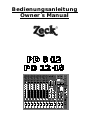
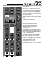
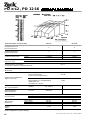
Bedienungsanleitung
Owner`s Manual
PD 8·12
PD 12·16
PD 8·12
1
2
3
4
5·
6 · 7/8
5/6
7 · 9/10
8 · 11/12
Insert
Mon Out
Effects
Effects 2
Footswitch on/off
Send
Left
Mic
Mic
Mic
Mic
Mic
Mic
Mic
Left
Mic
Line Out
Right
Right
Line
Line
Line
Line
Insert
Insert
Insert
Insert
Left/
Mono
Left/
Mono
+35
+25
+35
+45
+15
+60
0
+25
+35
+45
+15
Gain
+60
0
+25
+35
+45
+15
Gain
+60
0
+25
+15
+60
0
+25
+15
Gain
+60
0
+45
+15
Gain
+60
0
+45
+15
Gain
+60
0
Limit
+25
+6
0 dB
0 dB
– 3 dB
–3
– 10 dB
– 10
– 20 dB
– 20
+45
+15
Gain
power desk
+ 6 dB
+35
+25
Right
Line
Right
+35
+25
Left/Mono
Line
Right
+35
+45
Left/
Mono
Line
Right
+35
+45
Gain
Left/
Mono
Line
Right
Return
Left/
Mono
2 x 300 Watts RMS
Processor Control
dyloc + DTC
Dynamic Limiter
Line In
Right
+60
0
Gain
Stand by
Program Eff 1
Program Eff 2
Left
Tape In
–10
+10
0
–10
High
+10
0
–10
High
+10
0
–10
High
+10
0
–10
High
+10
0
–10
High
+10
0
–10
High
+10
0
–10
High
+10
0
High
DTC
active
dyloc
active
Clip
Clip
Range
Range
Right
Delays
DTC
–14
+14
0
–14
Mid
+14
0
–14
Mid
+14
0
–14
Mid
+14
0
–14
Mid
+14
0
–14
Mid
+14
0
–14
Mid
+14
0
–14
Mid
dyloc
on
off
+14
0
Mid
active
1
16 msec
2
32 msec
3
64 msec
4
96 msec
5 128 msec
6 160 msec
7 224 msec
8 288 msec
9 352 msec
10 416 msec
11 480 msec
12 576 msec
13 672 msec
14 768 msec
15 896 msec
16 1024 msec
Program Eff 1
Enter
0
–16
+16
5
–16
Low
+16
5
–16
Low
+16
5
–16
Low
+16
5
–16
Low
+16
5
–16
Low
+16
5
–16
Low
+16
5
–16
Low
0
+16
5
Low
–10
+10
–10
0
10
5
0
Eff 1
10
5
0
Eff 1
10
5
0
Eff 1
10
5
0
Eff 1
10
5
0
Eff 1
10
5
0
Eff 1
10
5
0
Eff 1
5
0
Eff 2
10
5
0
Eff 2
10
5
0
Eff 2
10
5
0
Eff 2
10
5
0
10
5
Eff 2
0
10
5
Eff 2
0
+14
–14
+14
–10
Program Select
0
5
L
0
Mon
10
0
R
L
Pan
0
Mon
10
0
R
L
Pan
0
Mon
10
0
R
L
Pan
0
Mon
R
10
Mon
L
R
L
R
Pan
10
Clip
Clip
Clip
Clip
Range
Range
Range
Range
Range
0
0
Mon
L
R
L
R
Pan
Clip
4
0
0
3
5·
10
10
10
10
10
9
9
9
9
9
8
8
8
8
7
7
7
7
6
6
6
6
5
5
5
5
4
3
2
4
3
2
4
3
2
4
3
2
L
R
L
R
Mon
L
R
L
R
–14
Pan
+14
–14
+14
–14
Low Mid
Low Mid
0
0
+14
–14
Low
Dark
+14
Mid
0
+14
–14
Low
Clip
Range
10
Line In Volume
5
5
0
5
+14
0
Low
10
Repeat
Bright
Eff Filter
0
10
Tape In Volume
5
10
0
Eff 1 to Mon
10
Eff 2 to Mon
Headphone
Stereo
Range
Left/Right to Mon
Left
Right
Mon
Effect on
5
Effect on
7 · 9/10
8 · 11/12
10
10
10
10
10
10
10
10
9
9
9
9
9
9
9
9
8
8
8
8
8
8
8
8
8
7
7
7
7
7
7
7
7
7
6
6
6
6
6
6
6
6
6
5
5
4
3
2
4
3
2
5
4
3
2
5
4
3
2
5
4
3
2
5
4
3
2
5
4
3
2
5
4
3
2
5
4
3
2
5/6
6 · 7/8
10
0
Pan
Clip
Range
2
0
Mon
Pan
Clip
1
10
0
0
0
5
10
0
5
Eff 2
–14
0
8 9 10
11
12
13
14
3
15
2 1 16
7
Program Select
High
0
10
Line Out Volume
+10
High Mid
0
10
5
Eff 2
6
5
4
0
Eff 1
High Mid
10
Up
High
0
10
5
–14
0
Down
+10
High
0
5
0
Eff 1
Eff 2
0
10
Headphone Volume
Master Stereo
Ready
Stand by
Power Desk
Zeck Musi c · Tur nhal l enweg 6 · D- 7808 Wal dk i r ch 2
owners manual PD 8·12, PD 12·16
owner`s manual PD 8·12, PD 12·16 © 1993 Zeck Music
3
PD 8·12, PD 12·16 owners manual
1
Sehr geehrter Kunde,
Dear customer,
wir freuen uns, daß Sie sich für den Zeck PD
8·12 / PD 12·16 entschieden haben und und wir
wünschen Ihnen mit diesem Gerät viel Freude,
Kreativität und Erfolg!
Im folgenden wollen wir Ihnen die Bedienung des
Gerätes erläutern, aufgegliedert nach den Themen Eingangskanal, Mastersektion, Prozessorfunktionen, Effekteinheit und Anschlußmöglichkeiten.
first of all we would like to thank you for purchasing the ZECK PD 8·12 / PD 12·16 mixer and we
are sure that it will efficiently support you on your
way to musical creativity and success.
In the following chapters we want to explain to
you all the functions of the mixer, one by one, as
there are the input section, master section, processor functions, effect units and wiring facilities.
Mic
Line
Insert
+35
+25
+45
+15
+60
0
Gain
5 · 5/6
Mic
Left/
Mono
Line
Right
+35
+25
+45
+15
+60
0
4
Gain
owner`s manual PD 8·12, PD 12·16 © 1993 Zeck Music
owners manual PD 8·12, PD 12·16
0
–10
+10
0
–14
High
+14
0
–16
Mid
+16
5
0
Low
10
5
0
Eff 1
10
5
0
Eff 2
10
0
L
Gain
Mon
R
Pan
Clip
Eingangskanal
Input channel
Der PD 8·12 / PD 12·16 bietet zwei verschiedene
Eingangskanäle. Die Kanäle 5-8 (PD 8·12) bzw.
9-12 (PD 12·16) sind stereo ausgelegt, die übrigen Kanäle sind mono ausgelegt. Die Regelmöglichkeiten (Klang, Effekte etc) sind identisch, es
gibt jedoch Unterschiede in den Anschlußmöglichkeiten.
The PD 8·12 / PD 12·16 offers two different kinds
of input channels. On the PD 8·12 channels 5 to
8 are wired stereo while on the PD 12·16 channels 9 to 16 are stereo. The remaining channels
(1-4 and 1-8 respectively) are monaural, just as
on any other mixer. All mixer channels have identical controls, the difference between the two
channel groups lies within their input routings.
Bei dem Mono-Eingangskanal kann der Mikrofoneingang oder der Line-Eingang benutzt werden.
Die Insert-Buchse ermöglicht das Einschleifen
von Effekt-Geräten pro Kanal. Diese Stereo-Klinkenbuchse liegt elektrisch nach der Klangregelung. Die Spitze des Stereo-Klinkensteckers führt
das Send-Signal, der Ring das Return-Signal. Die
Insertbuchse kann auch als Ausgang (z.B. für
Mehrspurmaschinen) genutzt werden. In diesem
Fall wird ein Stereo-Klinkenstecker verwendet,
bei dem Ring und Spitze miteinander verbunden
sind. Der Ausgang (Spitze) hat dann Kontakt mit
dem Eingang (Ring), so daß der Signalweg im
Eingangsmodul nicht unterbrochen wird. Dieser
Ausgang bleibt unbeeinflußt vom Kanal-Fader.
Bei dem Stereo-Eingangskanal sind 2 Line-Buchsen für Stereo-Anwendung Left und Right vorhanden. Soll eine Mono-Quelle angeschlossen werden, so ist die obere Klinkenbuchse Left/Mono zu
verwenden.
Der Mikrofoneingang ist wie bei den anderen
Kanälen ein Mono-Eingang.
Line- und Mic-Buchsen können auch gleichzeitig
belegt werden, allerdings kann dies zur Folge
haben, daß die beiden angeschlossenen Geräte
sich gegenseitig in der Lautstärke beeinflussen.
Die XLR-Buchse Mic ist niederohmig symmetrisch ausgeführt. Hier können Mikrofone oder
andere niederohmige Quellen (z.B. Direktbox,
balanced out von Keyboards etc.) angeschlossen
werden.
Unterhalb der Mic-Buchse befindet sich die LineKlinkenbuchse. Sie ist gedacht für mittel- bis
hochohmige Quellen, also z.B. Keyboards, Instrumente, Bandgeräte etc.
Range
1
10
9
8
7
Mit dem Gain-Regler paßt man die Empfindlichkeit des Eingangkanals auf die Signalstärke der
angeschlossenen Quelle an. Die eingestellte
Empfindlichkeit wird durch Leuchtdioden, Range
(bei den Stereokanälen Range Links und Rechts)
und Clip angezeigt. Die Range-LEDs zeigen
durch ihr Aufleuchten an, wenn ein Signal am
Eingang anliegt. Die Clip-LED zeigt Verzerrungen
im Bereich der Eingangsverstärkung und der
Klangregelung.
When using a monaural channel one can use the
XLR microphone input or the line input jack. The
stereo insert jack acts as a separate serial effects
loop for each channel. When in use, the tip of the
stereo jack will carry the send signal from the
mixer while the ring expects the returning signal
from the external device. The insert jack can also
be used as a separate channel output e.g. for
recording purposes. In order to avoid shortening
or interrupting the signal chain, a stereo plug with
tip and ring terminals soldered together must be
used for this type of configuration.
All stereo channels feature two line input jacks
which route their input signals to their assigned
stereo outputs. If you want to use a stereo channel as a monaural channel just use the upper
input jack (left/mono) as an input. The microphone input is always wired monaural.
Microphone and line inputs on each channel can
be used simultaneously, but you should keep in
mind that the output volume controls of the
connected instruments might counteract in some
cases.
The XLR microphone input is designed as a lowimpedance symmetrical input to connect all kinds
of microphones and other low-impedance sources such as outputs from DI-Boxes or balanced
outputs of electrical instruments or amplifiers.
The line input jack below the XLR input is designed for high input impedance and unsymmetrical connection. It is best suited for all kinds of
instruments such as keyboards, tape recorders,
pickup systems etc.
The gain control affects the input sensitivity of
each channel. The yellow “range” LEDs (two of
them on each stereo channel) light up whenever
the signal strength is sufficient. Overshooting the
required gain setting results in clipping (and
distortion) of the signal causing the red “clip” LED
to light up as a warning.
For best results in signal-to-noise ratio set the
gain control so that the red LED does just not
flash during very loud passages.
Der Gain-Regler sollte so eingestellt werden, daß
die gelben Range-LEDs kräftig leuchten, die rote
Clip-LED aber gerade noch nicht anspricht. So ist
sichergestellt, daß am Eingang optimale Pegelverhältnisse herrschen und daß Störgeräusche
wie Brummen und Rauschen minimiert werden.
6 12·16 © 1993 Zeck Music
owner`s manual PD 8·12, PD
5
PD 8·12, PD 12·16 owners manual
0 dB
Klangregelung
Tone Control (Equalizer)
Die Klangregelung ist in drei Bänder aufgeteilt:
High-Regelung bei 10 - 20 kHz mit ± 10 dB,
● Mid-Regelung bei 1 kHz mit ± 14 dB,
● Low-Regelung bei 60 Hz mit ± 16 dB.
Die Klangregelung sollte normalerweise linear
stehen (alle Regler auf ‘0’) und sollte nur dann
vorsichtig benutzt werden, wenn bestimmte
Soundvorstellungen oder die örtliche Akustik dies
erfordern. Es macht keinen Sinn, alle Klangregler
an den Anschlag zu drehen (vgl. Marshall-Syndrom), denn dies würde in jedem Fall zu einer
Verschlechterung des Klangbildes führen.
The PD’s channel equalizer section is capable of
controlling three different ranges of the sound
spectrum :
● high frequencies from 10 kHz to 20 kHz with a
boost/cut of ± 10 dB
● midrange frequencies around 1kHz with a
boost/cut of ± 14 dB
● ow frequencies around 60Hz with a boost/cut
of ± 16 dB
– 3 dB
– 10 dB
●
– 20 dB
Stand by
dyloc
active
Mit den Eff1- und Eff2-Reglern kann man einen
beliebigen Anteil des Eingangsignals auf den
internen Effekt 1 (99 Programme, Hall/Spezialeffekte) und den Effekt 2 (16 Delay - Programme )
geben.
Die Effektwege liegen `post-fade`, d.h. sie sind
dem Kanal-Fader nachgeschaltet. Dies bedeutet,
daß an den Eingängen der Effekte nur dann ein
Signal anliegt, wenn auch der Kanal-Fader auf ist.
dyloc
on
off
active
0
+10
–10
+10
High
High
0
+14
–14
High Mid
+14
High Mid
0
+14
–14
Low Mid
+14
Low Mid
0
+14
–14
Low
Low
Left
6
+14
Der Mon-Regler legt einen beliebigen Anteil des
Eingangsignals auf den Monitorweg.
Der Monitorweg liegt ’pre-fade‘, d.h. er ist dem
Kanal-Fader vorgeschaltet. Am Ausgang ‘Mon
Out’ liegt auch dann ein Signal an, wenn der
Kanalfader ganz zu ist.
Der Regler Pan (Panorama) verteilt das Eingangssignal anteilig auf die Masterschienen
links/rechts. Steht Panorama in der Mittelstellung
(0), so wird das Eingangssignal gleich stark nach
links und rechts verteilt. Bei stereo-Anschluß
eines Kanals ist der Panorama-Regler auch in
Funktion, allerdings liegen die stereo-Kanäle
grundsätzlich links und rechts, so daß der Panorama-Regler dann nur den einen oder anderen
Kanal ausblenden kann. Bei Mono-Belegung des
Kanals über den Klinkeneingang Left/Mono ist der
Panorama-Regler normal in Funktion.
Mit dem Kanal-Fader stellt man die Kanallautstärke ein.
Falls die Clip-LED anspricht, muß der Gain-Regler zurückgedreht und der Kanal-Fader aufgezogen werden.
As a general rule of thumb, the tone controls
should be set for a moderate equalization, as this
is the best way to achieve a natural sound reproduction. The general idea of channel equalization
is to compensate for differences in the sound
sources rather than trying to make poor microphones or instruments sound better.
The controls “Eff 1” and “Eff 2” act as send controls into the built-in effect units Effect 1
(reverb/special effects) and Effect 2 (delay).
These two controls are “post fade” in the signal
chain. This means that the signals send into the
effect units are also decreased gradually when
the channel faders are being pulled down and
that there is no effect signal audible when the
faders are fully down.
Next feature going down the channel knobs is the
“Mon” control. This control allows the user to
send a division of the channel signal to the monitor section which again controls the overall monitor output of the mixer. The “Mon” controls work
“pre-fade” which means that they are not affected
by the channel fader settings but only by the gain
controls and the equalization. This leads to the
positive effect that a musician is still able to control himself by a monitor control signal from a
channel even when it is faded out.
The “pan” control finally determines how much of
the channel signal is send to the left or right
master section of the mixer. When in center position, the channel signal is routed to the left and
right side of the master section in equal proportions, while a rotation to either side makes the signal travel between left and right making it possible to place the channel signal somewhere in the
stereo image. When the channel is used stereo,
the two channel signals are stuck with their assigned sides and unable to move inside the stereo
image so the “pan” control works in fact as a
“balance” control as found on home stereo equipment.
Finally, the channel fader rules over the output of
the channel into the master section.
If you notice that the red “clip” LED is lit or flashing too often, turn the gain control down and
bring the channel fader up to compensate for a
constant volume.
Right
10
10
9
9
owner`s manual PD 8·12, PD 12·16 © 1993 Zeck Music
owners manual PD 8·12, PD 12·16
Mastersektion
Mit den Master-Fadern wird die Gesamtlautstärke des Gerätes
eingestellt. Der Gesamtpegel wird über die zweireihige LEDZeile angezeigt. Diese Anzeige ist an den Endstufen-Eingangspegel gekoppelt. Die rote Limit-LED leuchtet auf, wenn der
dynamische Limiter in Funktion tritt und das Endstufensignal
begrenzt. Dadurch werden die sonst üblichen durch Clipping
hervorgerufenen Verzerrungen vermieden. Dies schützt die
Endstufen und Lautsprecher vor Beschädigung.
rektur DTC gleitend zurückgeregelt, entsprechend verliert dann
die LED an Helligkeit. Bei Maximalleistung ist die Prozessorregelung auf den Linearwert zurückgestellt und der dynamische
Limiter geht in Funktion.
Klangregelung
Die 4-Band-Klangregelung dient zur Anpassung der Anlage an
die jeweilige Raumakustik. Die Frequenzen liegen zur besseren
Regelbarkeit anders als im Eingangskanal:
●
●
●
●
High-Regelung bei 11 kHz mit ± 10 dB,
High Mid-Regelung bei 2.7 kHz mit ± 14 dB,
Low Mid-Regelung bei 330 Hz mit ± 14 dB,
Low-Regelung bei 80 Hz mit ± 14 dB.
Der High-Regler sollte vorsichtig eingestellt werden, bei zu viel
Höhen steigen Rauschanteile und Rückkopplungsgefahr.
Die Insert Buchse ermöglicht das Einschleifen eines Effektgerätes (z.B. zusätzlicher grafischer EQ) vor der Endstufe. Die
Buchse ist als Stereo-Klinkenbuchse ausgeführt. Die Belegung
ist gleich der des Inserts im Eingangskanal (Spitze = Send,
Ring = Return, Masse).
dy l oc ® -Processing
Mit dem Schalter dy l oc ® -on wird der eingebaute Prozessor
aktiviert.
Es dauert nach dem Einschalten ca. 3 Sekunden, bis der Prozessor aktiv wird. Die nach dieser Zeit dann hörbare Klangverbesserung wird optisch durch Aufleuchten der dy l oc ® activeLED angezeigt. Ebenso erlischt die Anzeige-LED beim Ausschalten erst nach einer gewissen Zeit, erst dann arbeitet die
Endstufe wieder linear.
Während des Betriebes wird über die Helligkeit dieser LED der
Arbeitszustand des dy l oc ® -processings angezeigt. Mit zunehmender Lautstärke werden Baßkompensation und Höhenkor-
owner`s manual PD 8·12, PD 12·16 © 1993 Zeck Music
7
PD 8·12, PD 12·16 owners manual
–3
Master section
– 10
ges the processor will become fully deployed
again as shown by the brightening LED.
The master section controls the overall output of
the PD mixer. A two-rowed LED-bar displays the
signal level after it has
passed the master faders and the master EQ
controls, just before it enters the built-in power
amplifier. The red ‘Limit’ LED above the display
lits up whenever the dynamic limiter takes over
automatically and prevents the signals from
being clipped inside the power amplifiers. By
doing this, the dynamic limiter makes it impossible to create distorted signals by overloading the
ampifiers, a common source of speaker damage
or
electronic hazard.
– 20
EQ section
The 4-band master EQ section provides control
over the total sound coming out of the PD. It
makes it possible for the user to compensate for
shortcomings in the acoustical environment or the
PA-System. For greater versatility, the master
tone controls have center frequencies that differ
from the ones in the channels:
treble control at 11kHz with ±10 dB boost/cut
high-mid control at 2.7kHz with ± 14 dB
boost/cut
● low-mid control at 330Hz with ± 14 dB boost/cut
● low frequency control at 80Hz with ± 14 dB
boost/cut
●
●
0
–10
+10
High
0
–14
+14
Mid
Treble control settings towards the boost side
should be done carefully as the danger of acoustical feedback is especially prominent in this frequency range. Also, excessive amounts of treble
boost always yield more unwanted audible hiss.
The master insert jacks allow the user to connect
external devices such as additional EQs or digital
effects between the master output stage and the
power amplifier inputs. The two jacks are wired
the same way as the inserts on the channels, tip
being ‘send’ and ring being ‘return’.
0
dy l oc ® -processing
The dy l oc ® -processor is activated by pushing the
–14
+14
Low
Left/Right to Mon
Mon
10
9
8
‘dy l oc ® -on/off’ button above the master EQ-controls.
It takes about 3 seconds for the processor to
become active which is indicated by the ‘dy l oc ® active’ LED above the button. By the same time
the improvement of the sound reproduction will
become noticeable. Pushing the same button
again disactivates the dyloc-processor within
about 3 seconds, putting the amplifiers back to
linear mode.
During operation, the ‘dy l oc ® active’ LED gives
information about the state of the processor circuitry by its brightness. At higher sound levels the
LED will become more and more dim due to the
fact that the dy l oc ® -processor intetionally reduces its influence. At less powerful music passaowner`s manual PD 8·12, PD 12·16 © 1993 Zeck Music
owners manual PD 8·12, PD 12·16
– 3 dB
–3
– 10 dB
– 10
– 20 dB
– 20
Program Eff 1
Stand by
DTC
active
dyloc
active
Program Eff 2
Clip
Clip
Range
Range
Delays
DTC
active
dyloc
on
off
Program Eff 1
Enter
0
0
dy l oc ® -processor
Im Folgenden wollen wir die Funktionsweise des Zeck dy l oc ® processors kurz erläutern.
1. dy l oc ® -Baßkompensation
Bedingt durch die Konstruktion von hart aufgehängten PA-Lautsprechern (die Schwingspule ist extra gleich lang wie der
Magnetspalt), verläßt die Schwingspule bei großen Auslenkungen im Baßbereich teilweise den Magnetspalt. Dies führt zu
nichtlinearen Verzerrungen innerhalb der Baßwiedergabe.
Die Zeck-dy l oc ® -Technik kompensiert diese Verzerrungen
schon in der Entstehung durch Korrektur der Phasenlage und
Amplitude.
Diese Phasen- und Amplitudenkorrektur arbeitet dynamisch,
d.h. es wird ständig der momentane Belastungszustand des
Lautsprechers überwacht. Die Amplitudenkorrektur ist dem
tolerierten Maximalhub des Lautsprechers unterstellt und wird
mit zunehmendem Pegel gleitend dynamisch ausgeregelt.
Durch dieses Regelsystem wird die Gefahr einer thermischen
Überlastung des Lautsprechers minimiert.
Die Zeck dy l oc ® -Schaltung ist technisch so realisiert, daß die
Klangkorrektur im hörbaren Bereich zwischen 30 und 80 Hz
vollzogen wird. Tiefere Frequenzen werden nicht beeinflußt, um
unnötige Belastungen im nicht hörbaren Bereich zu vermeiden.
Je Kanal ist eine doppelte Überwachungs- und Korrekturregelung vorhanden, bei welcher intelligente Filter aus der Digitalund Analogschaltungstechnik zur Anwendung kommen. Das
Ausgangssignal zur Box wird ständig gemessen, digital umgesetzt und über digitale Regelkreise behandelt. Die gesamten
Regelkreise arbeiten extrem schnell und sauber.
1
16 msec
2
32 msec
3
64 msec
4
96 msec
5
128 msec
6
160 msec
7
224 msec
8
288 msec
9
352 msec
10 416 msec
11 480 msec
12 576 msec
13 672 msec
14 768 msec
15 896 msec
16 1024 msec
0
Line Out V
gelt, so daß bei Maximalleistung der Frequenzgang wieder linear ist. Dies bewirkt ein offeneres, dynamischeres Klangbild bei
gleichzeitiger Vermeidung von Aggressivität bei hohen Lautstärken.
Die Höhenkorrektur DTC kann dem dy l oc ® -processing zugeschaltet werden. Ohne aktiviertes dy l oc ® -processing kann die
Höhenkorrektur nicht betrieben werden.
Die Funktionsweise der gesamten dy l oc ® -Technik ist vereinfacht in der folgenden Grafik dargestellt.
2. Höhenkorrektur
Zur Optimierung des Klangbildes und zur Verbesserung der
Durchsichtigkeit ist beim PD 8·12 / PD 12·16 eine dynamisch
geregelte Höhenkorrektur eingebaut: Zeck DTC
Im Obertonbereich ab ca. 8 kHz werden die Höhen leicht angehoben und mit zunehmender Lautstärke dynamisch ausgereowner`s manual PD 8·12, PD 12·16 © 1993 Zeck Music
9
PD 8·12, PD 12·16 owners manual
dy l oc ® -processor
Program Eff 1
Program Eff 2
Clip
Clip
Range
Range
Delays
1
16 msec
2
32 msec
3
64 msec
4
96 msec
5
128 msec
6
160 msec
7
224 msec
8
288 msec
9
352 msec
10 416 msec
11 480 msec
12 576 msec
13 672 msec
14 768 msec
15 896 msec
16 1024 msec
Program Eff 1
Enter
Down
Up
8 9 10
11
6
12
5
13
4
14
3
15
2 1 16
7
Program Select
Program Select
0
5
5
Dark
5
0
10
Bright
Eff Filter
Repeat
5
5
At this point we would like to explain in
short terms how the dy l oc ® -processor
works.
A common feature of all hard-suspensed high-powered PA speakers is that
the voice coil has about the same
lenght as the magnetic gap that it
moves in. As the speaker cone, and
thus the voice coil, is being displaced,
part of the voice coil leaves the
magnetic field and can no more contribute to the force that moves the cone.
This effect violates the linearity of the
transducer system and leads to
increased distortion, especially in the
low frequency range.
The dy l oc ® -processor deals with this
shortcoming by correcting phase and
amplitude of the outgoing signal dynamically. The dy l oc ® ·processor continuously senses the actual stress
being put on the speaker and is able
to look after the amplitude margin of
the speaker cone.
With this control system, the danger of
overheating of the speaker’s voice coil
is significantly reduced. Only frequencies in the audible low-frequency
range between 30 Hz and 80 Hz are
being
influenced, so that there is no power
wasted on non-audible
infrasound.
Each channel has its own two-stage
control and correction system making
use of intelligent filters put to work by
means of digital and analogue circuitry. The output signal going to the
speakers is constantly measured and
transformed into digital control signals
which work extremely fast and accurate.
pushing the button to the left of the
‘dy l oc ® on/off’ button. Note that the
DTC is only working when the
dy l oc ® ·control is already activated.
DTC-control
0
10
0
Eff 1 to Mon
Effect on
Eff 2 to Mon
Effect on
Eff 1
10
10
Eff 2
10
10
9
9
8
8
For a more ‘open’ sound quality and
enhanced transparency a newly developed treble-correction system has
been added to the PD 8·12 and PD
12·16 : the Zeck DTC.
The DTC does the same sound correction that the dy l oc ® alone does to
the bass frequencies but ‘mirrors’ it to
the overtone side of the sound spectrum around 8 kHz, giving an even
more drastic inprovement of the overall sound coming out of the PD. Sharing the dynamic features with the
dyloc, the DTC never makes the
sound too sharp at high-volume passages, as its influence is also gradually reduced as the sound level increases.
The DTC-control facility is added by
owner`s manual PD 8·12, PD 12·16 © 1993 Zeck Music
owners manual PD 8·12, PD 12·16
PD 8·12
Effects
Effects 2
3. Dynamischer Limiter
Footswitch on/off
Send
Left
Line Out
Right
Return
Left/Mono
Right
power desk
Left/
Mono
2 x 300 Watts RMS
Processor Control
dyloc + DTC
Dynamic Limiter
Line In
Right
Program Eff 1
Program Eff 2
Clip
Range
Range
1
16 msec
2
32 msec
3
64 msec
4
96 msec
5
128 msec
6
160 msec
7
224 msec
8
288 msec
9
352 msec
10 416 msec
11 480 msec
12 576 msec
13 672 msec
14 768 msec
15 896 msec
16 1024 msec
Enter
Down
Up
deutliche Qualitätsverbesserung des
Klangbildes im Baß- und Höhenbereich
●
erhöhter Schutz der Lautsprecher durch
dynamische Basskorrektur
●
Überlastschutz des gesamten Systems durch
dynamisch kontrollierten Limiter
●
Dynamikgewinn für das Gesamtsystem durch
Zusammenwirken von dy l oc ® -Schaltung und
dynamischem Limiter
Right
Delays
Program Eff 1
●
Left
Tape In
Clip
Neben der Zeck dy l oc ® -Schaltung und der Höhenkorrektur
DTC, welche völlig eigenständig das Klangverhalten im Bassund Höhenbereich optimieren, kommt ein unabhängig arbeitender dynamisch kontrollierter Limiter zum Einsatz. Er erkennt
pro Kanal das Auftreten nicht linearer Betriebszustände wie
z.B. Übersteuerung oder falsche Impedanz und regelt entsprechend das Eingangssignal nach einem akustisch optimierten
Algorithmus aus. Diese Regelung ist so aufgebaut, daß keine
Dynamik-Verluste entstehen.
Beide Regelsysteme - die Zeck dy l oc ® -Schaltung sowie der
dynamisch kontrollierte Limiter - sind aufeinander abgestimmt
und ergänzen sich in der Form, daß folgende Vorteile realisiert
wurden:
5
0
10
Line Out Volume
8 9 10
11
12
13
14
3
15
2 1 16
5
Der Monitorweg
Der Mon-Fader legt die Summenlautstärke der Monitorwege
fest. Sollen Monitore über diesen Weg betrieben werden, muß
allerdings noch eine Monitorendstufe nachgeschaltet werden
(oder man schließt einen Aktiv-Monitor direkt an der Buchse
‘Mon Out’ an, z.B. Zeck MS12/2 aktiv).
7
6
5
4
Program Select
Program Select
0
5
5
Dark
5
0
5
10
Line In Volume
5
10
Repeat
Bright
Eff Filter
0
Die Taste ‘Left/Right to Mon’ legt das Mastersignal Left/Right
auf den Monitor. Die Mon-Regler in den Eingangskanälen
haben dann keinen Einfluß mehr auf das Monitorsignal.
0
10
Tape In Volume
Mit der Monitor-Klangregelung läßt sich das Monitorsignal auch
klanglich auf die Gegebenheiten der Bühne einstellen und es
lassen sich z.B. Rückkopplungen minimieren. Die Frequenzen
sind im einzelnen:
● High-Regelung bei 10 kHz mit ± 10 dB,
● Mid-Regelung bei 1.5 kHz mit ± 14 dB,
● Low-Regelung bei 90 Hz mit ± 14 dB.
5
Die 6-stellige LED-Zeile zeigt den Level des Monitorpegels an.
0
10
0
Eff 1 to Mon
10
Eff 2 to Mon
Headphone
Stereo
Effect on
5
Effect on
Eff 1
Eff 2
0
10
Headphone Volume
Master Stereo
10
10
9
9
8
8
7
7
Ready
Stand by
owner`s manual PD 8·12, PD 12·16 © 1993 Zeck Music
11
PD 8·12, PD 12·16 owners manual
Do not remove cover before
disconnecting mains plug
R
AC-Voltage:
PD 12·16
230 V
Ser. Nr.:
processor controlled stereo power mixer
biMOS-technology · dyloc pr
Fuse
6A
250 V MT
Power
Speaker out
Phantom Power
Channel 1–4
ocessing · DTC · dynamic limiter
2
Left
1
3
min. 4 Ω
Right
Mic Input
1 = Shield
2 = + Life
3 = – Life
1
2
3
Speaker Out
1 = Shield
2 = Life
Cont. Output Power / 4 Ohms: 300 W RMS / 300 W RMS
Output Power Cont. Program / 4 Ohms:
2
3
1
Insert
1 = Shield
2 = Send
3 = Return
2
1
Speaker Out Jack
1 = Shield
2 = Life
450 W / 450 W
Dynamic limiter
●
●
Besides the dy l oc ® and DTC processors that optimize the frequency response in the treble and bass range, the PD 8·12
and PD 12·16 employ an independent built-in dynamic limiter.
It watches over the power amplifiers by detecting non-linear
conditions in the output stages, e.g. overloading or impedance
mismatching, and counteracting them by adjusting the input
signal of the power amplifiers following an algorithm that has
been specially calculated according to acoustical requirements.
No dynamic loss however is noticeable whenever the limiter
switches itself into action.
Both control systems, the Zeck dy l oc ® ·processor and the
dynamic limiter, are perfectly adjusted to each other and support each others operations resulting in the following benefits :
●
high-control at 10 kHz with ± 10 dB boost/cut
mid-control at 1.5 kHz with ± 14 dB boost/cut
ow-control at 90 kHz with ± 14 dB boost/cut
A row of 6 LEDs allows visual control over the PD’s monitor
signal output level.
distinct enhancement of the of the high and low
end reproduction of the sound spectrum
● increased safety for speakers by means of the
dynamic bass correction
● overload protection of the whole system
through the dynamic controlled limiter
● higher dynamics from the system by the
cooperation of dy l oc ® and limiter circuitry
●
The monitor path
In normal mode, the monitor-send signals from the channels
are collected at the ‘Mon’-Fader and level-adjusted alltogether
from here. Powering monitor speakers from the PD 8·12 and
PD 12·16 requires either an external amplifier or self-powered
active monitor speakers, e.g. the
Zeck MS 12/2 active.
The button ‘Left/Right to Mon’ switches the left and right master
output as a monaural mix to the monitor fader. Simultaneously
the monitor signals and controls from the channels are disconnected.
A 3-band equalizer has been added to the monitor section for a
more versatile control, as the acoustical circumstances on stages mostly differ from the audience hall. Also, feedback problems that inevitabely occur from a certain sound level on, can
be held under control by means of a monitor tone-control.
The EQ’s frequencies are in detail:
12
owner`s manual PD 8·12, PD 12·16 © 1993 Zeck Music
owners manual PD 8·12, PD 12·16
Die Effekteinheiten
The effect-units
PD 8·12 / PD 12·16 sind mit zwei digitalen Effektgeräten ausgestattet. Die Effekte werden jeweils mit der Taste ‘Effect on’ eingeschaltet, es leuchtet dann die grüne LED ‘Effect on’ und die
Nummer (1-99, 1-16) des Effektprogrammes wird ständig angezeigt. Wenn der Effekt ausgeschaltet ist, blinkt die Programmnummer.
Mit den Fadern werden Effect1 und Effect2 dem Mastersignal
zugemischt. Der ‘Eff to Mon’ - Regler mischt das Effektsignal
dem Monitorsignal zu.An der Klinkenbuchse ‘Effects Footswitch
on/off’ kann ein Fußschalter angeschlossen werden, der gleichzeitig auf beide Effekte wirkt. Der Fußschalter kann aber nur
denjenigen Effekt ein- und ausschalten, der mit der Taste
‘Effect on’ aktiviert ist.
Das richtige interne Aussteuern der Effektgeräte ist von sehr
großer Bedeutung bezüglich des Rauschpegels. Jeweils eine
Range- und eine Clip-LED erleichtern das richtige Aussteuern
(mit den Eff1- und Eff2-Reglern in den Eingangskanälen) der
Effektgeräte. Richtig ausgesteuert sind die Effektgeräte, wenn
die Range LED immer und die Clip LED gerade nicht leuchten.
Dann ist ein minimaler Rauschpegel gegeben.
The PD 8·12 and PD 12·16 come with two built-in digital effect
devices, Effect 1 and Effect 2. Each of them can be activated
by the pushbutton above the effect faders. When the effect is
on, the green LED above the effect fader is lit and the effectdisplay shows its number continuously. Turning an effect off
results in flashing of the program number display and the green
LED becomes dark. The overall volume of each effect is adjustable by the corresponding fader and the ‘Eff to Mon’ rotary
knobs allow to blend the effects into the monitor mix.
The jack ‘Effects Footswitch on/off’ can be connected with a
footswitch allowing to turn both effects on and off simultaneously. Only an effect that is activated by means of its pushbutton,
however, can be controlled via this footswitch.
A proper setting of the effect-send controls on the channels is
crucial for a noise-free effect operation. The same rules that go
with the channel gain settings apply here as well, there is a
‘range’ and ‘clip’ control for each effect. Just set all the ‘send’
controls from the channels as high as you can without the red
‘clip’ LED of the effects getting lit.
Einstell-Empfehlungen für die internen Effektgeräte
Alle digitalen Effektgeräte haben einen begrenzten Rauschabstand (Quantisierungsrauschen). Der Rauschabstand der integrierten Module liegen, je nach Programm, bei ca. 55 - 60 dB.
Der Rauschabstand der Eingangszüge liegt bei über 70 dB.
Wenn beim PD etwas rauscht, dann ist es die Effekteinheit. Um
dies zu vermeiden, sollte man folgende Einstellungen vornehmen:
Gain-Regler soweit aufdrehen, daß die rote Clip-LED gerade
noch nicht leuchtet.
Effect-Regler auf 5 - 9 stellen.
Kanal-Fader auf ca 75 - 80 % hochziehen.
So ist sichergestellt, daß das Eingangssignal zum internen
Effekt groß genug ist. Nur so ist ein brauchbares Verhältnis
Nutzspannung / Störspannung für die Effekte möglich.
Den Effect-Fader zieht man dann nur noch so weit hoch, bis
genug Effekt hörbar wird. In der Regel reicht es, den EffectFader bis etwa zur Mittelstellung hochzuziehen.
Recommended settings for the internal effect controls
As all digital sound processors produce a quantization noise,
the signal-to-noise ratio (S/N ratio) of digital effect units is limited to 55 - 60 dB, depending on the selected program. The S/N
ratio of the PD’s input channels is better than 70 dB, so if
something is hissing, it is most likely one of the effect units. To
avoid excessive audible hiss, one should follow these recommendations:
- see the gain controls on the channel so that the red ’clip‘ LED
does just not flash
- set the channel effect controls between 5 and 9
- operate the channel faders within 75 - 80% of their maximum
setting
Only with these settings a strong enough input signal is send to
the effect units resulting in a reasonable S/N ratio. The effect
faders should be pulled up just enough to make the effectsound clearly audible. Settings above half of the fader’s range
should not be necessary following the rules given above.
Effekt1
Der Effekt1 stellt 99 fest abgespeicherte Stereo-Programme zur
Verfügung, z.B. verschiedene Hallprogramme und Ping-Pong
Echo. Die Programme werden mit dem ‘Program Select’ - Regler vorgewählt und mit der ‘Enter’ - Taste aktiviert.
Wird der ‘Program Select’ - Regler nach rechts gedreht, erhöht
sich die Programmnummer, nach links gedreht wird die Nummer erniedrigt. Die vorgewählte Nummer wird durch zwei blinkende Punkte in der Nummernanzeige gekennzeichnet. Das
neue Programm hat solange keinen Einfluß, bis es durch das
Drücken der ‘Enter’ - Taste bestätigt wird.
Mit der Klangwaage ‘Eff Filter’ kann die Klangcharakteristik
des Effekt1 eingestellt werden. In der Mittelstellung findet keine
Klangbeeinflußung statt. In Stellung ‘Bright’ bleiben die Höhen
erhalten und die Bässe des Effektsignals werden abgesenkt. In
Stellung ‘Dark’ bleiben die Bässe des Effektsignals erhalten
und die Höhen werden abgesenkt.
Die Programmtypen sind in der beigelegten Liste und im
Anhang aufgeführt.
Effekt2
Der Effekt2 stellt 16 fest abgespeicherte Delay-Programme zur
Verfügung. Die den 16 Programm-Nummern zugeordneten
Verzögerungszeiten sind auf der Frontblende im Bereich des
Effect2 aufgedruckt.
Mit dem ‘Program Select’-Schalter werden die Programme
abgerufen und die Programmnummer wird angezeigt.
owner`s manual PD 8·12, PD 12·16 © 1993 Zeck Music
13
PD 8·12, PD 12·16 owners manual
Über den ‘Repeat’-Regler kann die Anzahl der Wiederholungen
des Delay-Signals eingestellt werden.
Zum Einschleifen eines externen Effektgerätes (stereo oder
mono) sind die Buchsen ‘Effect2 send’ und ‘Effect2 return
Left/Right’ vorgesehen. Werden diese Buchsen belegt, so ist
das interne Effektgerät ‘Effect2’ abgeschaltet. Die Drehregler
‘Effect2’ in den Eingangskanälen wirken dann auf das externe
Effektgerät, der Fader ‘Effect2’ wirkt dann auf das Return-Signal des externen Effektgeräts.
The ‘Effect 1’ unit contains 99 different programs, including
several kinds of reverb, delay (echo), special effects and combinations of them, all in stereo.
The programs are dialed by a continuous ‘endless’ incremental
rotary switch (‘Program Select’) that allows quick access to all
programs from both ways by turning it left or right. When the
number of the desired program appears in the ‘Program Eff 1’
display it will not be activated until the ‘Enter’ button has been
pressed. Until this, the old program that has been called up
before remains active and the new program number is seen
with a flashing point in the display. Pressing the ‘Enter’ button
activates the new program instantaneously.
A tone-control for the Effect 1 programs has been provided to
fit the overall effect unit’s sound to your personal liking (‘Eff Filter’). In the middle detent position of the rotary knob all frequencies pass unaltered for a linear frequency response. Turning the tone-control clockwise reduces the amount of bass frequencies with no effect on the high frequencies resulting in a
crisp, bright effect sound. Turning the ‘Eff Filter’ knob counterclockwise reduces the high frequencies leaving the low frequencies unaltered for a warm, darker sounding effect.
For a detailed description of these programs and useful hints
for using them please refer to the extra sheets that come with
the mixers.
The ‘Effect 2‘ unit features a 16-bit digital delay unit with 16 different preset delay times. Like on Effect 1, the delays can be
dialed through the ‘Program Select’ rotary knob, but no enter
button is needed here, the delay times changing instantaneously as you go through the program numbers. A printed-on table
above the ‘Program Select’ knob shows the corresponding
delay times. As for the Effect 1 unit refer to the extra sheets for
recommendations on setting the delay times.
The ‘Repeat’ knob below the ‘Program Select’ determines how
many times a delay is repeated.
Three effect loop jacks have been provided for connecting an
external stereo effect device to the PD 8·12 and PD 12·16.
Connecting these jacks automatically disables the internal
Effect 2 device but leaving the ‘Eff 2’ fader in function.
14
owner`s manual PD 8·12, PD 12·16 © 1993 Zeck Music
owners manual PD 8·12, PD 12·16
Sonstige Anschlußmöglichkeiten:
Der Line Out-Regler ist Stereo und regelt die Ausgangslautstärke des Mastersignals in Stereo, abhängig von der am Master
Fader eingestellten Gesamtlautstärke. Über diesen Line OutWeg kann man z.B. auf ein weiteres Mischpult gehen, weitere
Endstufen oder einen aktiven Subwoofer anschließen.
Der Line In-Regler ist ebenfalls stereo ausgeführt. Über den
Line In-Weg kann man ein beliebiges Stereo-Signal dem
Masterteil des PD 8·12 / PD 12·16 zuführen, z.B. das Ausgangssignal eines Submixers, das Stereo-Signal eines
Tonbandes (Pausenmusik) oder auch bei größeren PA’s, wenn
der PD 8·12 / PD 12·16 als Keyboard-Monitorsystem läuft, das
Monitorsignal der Haupt-PA.
Ein Tape-Deck oder ein CD-Player kann an den Cinch-Buchsen ‘Tape In’ angeschloßen werden und mit dem Stereoregler
‘Tape In Volume’ kann dieses Signal dem Masterteil zugemischt werden.
Ein Stereo-Kopfhörer kann über eine Stereoklinkenbuchse
angeschloßen werden, er ist in der Lautstärke regelbar und gibt
das Master-Stereo-Signal wieder.
Stand-by Schalter
Mit dem Schalter Stand by wird das Mastersignal Left/Right
geräuschlos ein- und ausgeschaltet. In Stand by-Funktion
leuchten die roten LEDs im Master-VU.
Additional wiring facilities
The ‘Line Out’ jacks allow to connect external sound equipment
such as mixers, amplifiers or active subwoofers to the PD.
Their output volume is controlled by the ‘Line Out Volume’ as
well as by the master faders.
If you want to use the PD’s power amplifiers for other equipment you can easily connect these devices through the ‘Line
In’ jacks. Useful applications are manifold : any line-level stereo
signal that needs no preamplifying will work well in this input,
e.g. a submixers’s output or the monitor output from a larger
mixer using the PD as a monitor amplifier. The input level is
adjusted by the ‘Line In Volume’ control and as the inputs are
placed before the master faders in the signal chain they are
affected by them as well.
The ‘Tape In’ inputs come in the form of two cinch-type RCA
phono jacks. They are useful for connecting playback-outputs
from stereo home equipment such as tape decks or CD-players
to the PD. Similar to the line inputs described above, the signals from this input can be blended into the mix by the ‘Tape In
Volume’ control and are also dependent on the master fader
settings.
A jack for stereo headphones with an own volume control is
provided for silent monitoring of the master signal just before it
reaches the master faders.
Power-Schalter
Mit dem Netzschalter ‘Power’ wird das Gerät ein- und ausgeschaltet. Die Endstufen werden zeitverzögert dazugeschaltet.
Beim Ausschalten unterbricht das Endstufenrelais sofort den
Kontakt zu den Lautsprechern, so daß sowohl Ein- als auch
Ausschalten völlig geräuschlos vor sich gehen.
Phantom Power
Für Kanal 1 bis 4 kann Phantomspeisung mit ca. 40 V eingeschaltet werden. Die Phantom-Spannung liegt dann an Pin 2
und Pin 3 an. Es können bei eingeschalteter Phantomspeisung
selbstverständlich auch dynamische Mikrofone angeschlossen
werden. Durch die extrem unterschiedlichen Impedanzen von
Mikrofon einerseits und Mischer andererseits fließt auch bei
ungünstigen Bedingungen (z.B. falsch gelötetes Kabel) kein
nennenswerter Strom über die Mikro-Schwingspule. Außerdem
sind die Signalwege im Mischer durch Kondensatoren gegen
Gleichstrom gesichert. Durch diese Phantom-Speisung ist es
also möglich, bis zu 4 hochwertige, phantomgespeiste Kondensatormikrofone anzuschließen.
Speaker Left, Right
Hier können pro Kanal zwei 8 Ohm Boxen angeschlossen werden, entweder mit Klinke oder XLR. Klinken- und XLR-Buchsen
sind jeweils parallel verbunden. Bei XLR-Anschluß ist Pin 2
heiß, Pin 1 Masse, Pin 3 bleibt frei.
Man sollte darauf achten, daß 4 Ohm Gesamtimpedanz je
Kanal nicht unterschritten werden. Man kann zwar niedrigere
Impedanzen anschließen, jedoch ist dann ein Überhitzen der
Endstufen möglich. In diesem Fall würde der Temperaturschutz
eingreifen und die Endstufen abschalten.
Lüfter
Ein eingebauter Lüfter kühlt die Endstufenblöcke zusätzlich von
der Innenseite her. Deshalb ist darauf zu achten, daß die Lüftungsschlitze nicht verdeckt werden. Der Lüfter ist temperaturgesteuert, bei niedriger Temperatur läuft der Lüfter mit niedriger
Drehzahl und ist nicht hörbar. Erst bei hoher Temperatur der
Endstufen kühlt der Lüfter mit seiner vollen Leistung.
So long, viel Spaß mit Zeck!
Stand-by switch
For short program interruptions use the ‘Stand by’ switch on the
front to mute the outgoing master signal without having to turn
off the whole unit. The ‘Stand by’ mode is indicated by the two
lowest red LEDs of the master LED display.
owner`s manual PD 8·12, PD 12·16 © 1993 Zeck Music
15
PD 8·12, PD 12·16 owners manual
Technische Daten / Technical Data
PD 8•12
PD 12•16
Eingangskanäle mono
Input channels mono
4
8
Eingangskanäle stereo
Input channels stereo
4
4
2 x 150 W
2 x 200 W
220 W
300 W
Nennleistung
Continious output power
8 Ohm
4 Ohm
Frequenzumfang
Frequency range
Mixer + Power Amp
Zeck Effekt
18 – 25 000 Hz (–2 dB)
30 – 14 000 Hz (–2 dB)
Gesamt-Klirrfaktor ohne Effekte
Total harmonic distortion (THD) with effects off
< 0,1 %
Intermodulationsverzerrungen
IM distortion
max. 0,02 %
Äquiv. Eingangsrauschen,
bezogen auf 200 Ohm
Equiv. input noise @ 200 Ohms
Geräuschspannungsabstand
Signal to noise ratio
Masterfader max.
Eingangsfader min., EQ Mittelstellung
Master fader max.,
Input fader min., EQ flat
Min. Anschlußimpedanz
Min. output impedance
Speaker
min. 4 Ohms
Ausgangsimpedanz
Output impedance
Line Out
300 Ohms
Eingangsimpedanz
Input impedance
Mic Input
Line Input
Line In
Abmessungen
Dimensions
Tiefe / Depth
Höhe / Height
Breite / Width
Gewicht
Weight
– 124 dB
– 73 dB
2,2 kOhms
10 kOhms
22 KOhms
520 mm
200 mm
584 mm
520 mm
200 mm
684 mm
27 kg
29 kg
2 Jahre Vollgarantie / 2 years waranty
16
owner`s manual PD 8·12, PD 12·16 © 1993 Zeck Music
owners manual PD 8·12, PD 12·16
Block Diagram
owner`s manual PD 8·12, PD 12·16 © 1993 Zeck Music
17
PD 8·12, PD 12·16 owners manual
Power switch
The whole PD unit is turned on and off with the ‘Power’ mains
switch on the rear of the mixer. When the power is turned on
or off, the power amplifiers and speaker outputs are always
automatically switched with a little delay for a 100% silent performance.
Phantom Power
Channels 1 through 4 on the PD 8·12 and PD 12·16 are equipped with a switchable 40V phantom-power supply that can be
activated by a switch on the rear next to the mains power
switch. The built-in phantom power supply allows to operate up
to 4 high-quality condenser microphones with the PD, but also
dynamic microphones can be operated safely with the phantom
power activated as the design of the microphone inputs allows
no DC current to flow into the microphone coils through the signal path.
Speaker left and right
Each speaker output is capable of driving a minimum speaker
load of 4 ohms. The jacks and XLR sockets on each channel
are wired parallel. On the XLR outputs pin 3 carries the hot signal and pin 1 is ground, pin 3 is not used and has no connection.
Care should be taken not to connect impedances of less than
4 ohms to each output, as this might lead to overheating of the
output amplifiers, causing the thermal protection to become
activated. As a common example, two 8 ohm cabinets per
channel wired parallel or one 4 ohm cabinet per channel are
safe.
Cooling fan
For increased protection against overheating of the power stages a cooling fan has been built inside the mixers housing. To
operate safely, the ventilation slots need some clearance to get
rid of the air and should not be covered. Silent operation is
achieved by a two-stage fan speed control that runs slow at
lower temperatures. When the mixer is being operatied at full
power for a prolonged time the fan is switched to high speed
automatically.
So long, and lots of fun with Zeck.
Soundbeschreibungen Multi-Effects-Processor
Gruppe “Hall” , Programme 1-16 und 65-72
Dieser Halleffekt simuliert das Nachklangverhalten verschieden
großer Hallen. Aufgrund des relativ neutralen Klangbildes ist
dieser Effekt für alle möglichen Instrumente und Gesang universell einsetzbar. Es stehen Nachhallzeiten von 0.5s bis 15s
(!) zur Verfügung. Mit zu langen Nachhallzeiten über 3s sollte
man eher vorsichtig umgehen, um verwaschene Klangbilder zu
vermeiden. Sie eignen sich für eher sparsame musikalische
Arrangements. Die Gruppe “Hall Bright” (Programme 1-16) ist
höhenbetont ausgelegt, während die Gruppe “Hall Dark” (Programme 65-72) ein etwas dunkleres Nachhallbild erzeugt.
Diese Unterschiede können nach Bedarf durch die eingebaute
Effekt-Klangregelung angeglichen oder verstärkt werden.
Gruppe “Room”, Programme 17–32
In dieser Gruppe wird das akustische Verhalten verschieden
großer Räume nachgebildet. Wichtig für die klangliche Wirkung
eines Raumes sind vor allem die Reflexionen, die von seinen
Wänden ausgehen. Im Effektgerät des PD 12/16 sind zwei verschieden große Raumtypen verwirklicht, die noch jeweils in
ihrer Nachhallzeit variiert werden können. Diese Hallgruppe
eignet sich hervorragend dazu, alle Arten von Percussion und
Schlagzeug lebendiger klingen zu lassen. Auch Instrumentalsoli wie Saxophon oder E-Gitarren werden durch diesen Effekt
positiv angereichert. Alle Room-Programme sind “bright” ausgelegt da sie höhenbetont am besten zur Geltung kommen. Es
besteht allerdings wie bei allen Effekten die Möglichkeit, mittels
des Effekt-Klangreglers Korrekturen nach eigenem Geschmack
vorzunehmen.
Gruppe “Plate”, Programme 33-48
Hallplatten wurden in früheren Zeiten zur Erzeugung hochwertiger Nachhalleffekte eingesetzt. Auch die in Gitarrenverstärkern
oft vorhandenen Hallspiralen gehören in diese Gruppe der
mechanischen Nachhallerzeugung. Obwohl sie im digitalen
Zeitalter etwas aus der Mode gekommen sind, schwören noch
viele Benutzer auf den ‘Sound’, den diese Geräte produzierten.
Aus diesem Grunde wurden im PD 12/16 16 verschiedene
‘Plate’-Nachhallprogramme integriert, die das klangliche Verhalten dieser Geräte simulieren. ‘Plate’-Programme geben dem
Klangbild eine traditionellen, ‘nichtdigitalen’ Charakter. Sie eignen sich für alle Arten von Instrumenten, besonders Tasteninstrumente und Gitarre, aber auch für Gesang.
Gruppe “Gate”, Programme 49-56
Bei dieser Effektgruppe klingt der Nachhall nicht langsam aus,
sondern wird nach einer bestimmten Zeit abgeschnitten. Da ein
solches Nachhallverhalten in der Natur nicht vorkommt, wirkt
dieser Effekt sehr technisch und läßt sich am besten verwenden um Percussion und Schlagzeug einen zeitgemäßen Sound
zu geben. Auch Bläserinstrumente werden mit diesem Effekt
wirkungsvoll in Szene gesetzt.
Gruppe “Reverse”, Programme 57-64
Bei einem Reverse-Hall wird der natürliche Hallverlauf, wie er
etwa in den ersten Effektgruppe ‘Hall’ erscheint, zeitlich gespiegelt wiedergegeben. Der wiedergegebene Ton wird rückwärts
‘abgespielt’, schwillt also langsam an, um dann abrupt abzubrechen. Dieser Effekt klingt noch synthetischer als die ‘Gate’-Programme. Man kann mit diesem Effekt den Klang rückwärts
abgespielter Instrumente nachahmen, was ab und zu bei
Schlagzeugen und Gitarren für einen psychedelischen Effekt
eingesetzt wird.
18
owner`s manual PD 8·12, PD 12·16 © 1993 Zeck Music
owners manual PD 8·12, PD 12·16
Gruppe “Reverb + Stereo-Delay”, Programme 73-80
In dieser Gruppe ist die Nachhallzeit auf einen gebräuchlichen
Wert von 2,4s eingestellt, die Verzögerungszeiten des darübergelegten Echos verlängern sich mit steigender Programmnummer. Der Stereo-Effekt wird durch zeitliche Versetzung der links
und rechts gelegenen Echos erzeugt, was dem Gesamtklang
eine angenehme Räumlichkeit verleiht.
An dieser Stelle ein wichtiges Wort über Echo (Delay)-Effekte :
bei Auswahl von Delay-Effekten sollte man darauf achten, daß
die Echozeiten ungefähr mit dem Tempo der Musik übereinstimmen. Das Tempo wird meistens in ‘Schläge pro Minute’
(beats per minute = bpm) angegeben. Ein Beispiel : eine DelayZeit von 200ms (= 200 Millisekunden) erzeugt in der Sekunde 5
Echos und in der Minute 300 Echos. Diese Delay-Zeit passt
also zu allen Musiktempi, die sich durch das Teilen von 300
ergeben, also 300, 150 oder 75. Meistens wird man aber umgekehrt rechnen wollen. Man geht dabei am besten nach folgender Formel vor:
Delay Zeit = 30 000
bpm
Ein Tempo von 130 bpm führt nach dieser Formel auf eine
Delay-Zeit von 230ms, was im PD 12/16 dem Programm 73
entspricht. Aber auch Programm 73 mit der halben Delay-Zeit
von 110/125 ms würde passen, es würde allerdings wegen der
schnelleren Echos ewtas hektischer klingen. Die Hälfte davon,
60ms, wäre schon etwas zu kurz um einen rhythmischen
Delay-Effekt zu erzeugen. Man sollte im Allgemeinen DelayZeiten über 120ms anstreben. Wenn etwas kürzere Delay-Zeiten als die errechneten eingestellt werden, treibt das Echo den
Rhythmus nach vorn, während etwas längere Delay-Zeiten
dazu neigen, das Tempogefühl zu entspannen.
Der PD 12/16 enthält in seinen beiden Effektmodulen eine
reichhaltige Auswahl an Delay-Zeiten, so daß hier für praktisch
jedes Tempo ein passender Effekt vorhanden ist.
In der Soundtabelle für beide Effektgeräte des PD 12/16 sind
für alle Delays die Musiktempi angegeben, bei denen sie bevorzugt eingesetzt werden sollten.
Gruppe “Room+Delay”, Programme 88-92
Elektrischen Instrumenten, die direkt an den Mischer angeschlossen werden, fehlt oft der räumliche Klang eines Verstärkers, was zu einem trockenen Klangbild führt. Die Effekte dieser Gruppe bilden eine sehr schöne Mischung eines mittelgrossen Raumeffektes mit darübergelegten Stereo-Delays, was
dem Klang die fehlende Räumlichkeit wiedergibt. Sehr gut
geeignet für alle Instrumente, besonders für verzerrte Gitarre.
Gruppe “Stereo-Delay”, Programme 93-96
Hier wurden ultralange Delays mit verschiedenen Verzögerungszeiten links und rechts verwirklicht. Die Verzögerungszeiten links und rechts stehen nicht im ganzzahligen Verhältnis
zueinander, somit können diese Delays für die verschiedensten
Musiktempi angewendet werden.
Gruppe “Ambience”, Programme 97-99
Diese 3 Effekte erzeugen ein künstliches räumliches Klangbild
durch Mischung von Hall- und Delayeffekten. Für Gelegenheiten, bei denen die Lautsprecherboxen eng zusammen in kleinen Räumen stehen, können diese Effekte den Klang mehr im
Raum verteilt und weniger konzentriert erscheinen lassen. Programm 97 erzeugt einen Hall-Raum mit darübergelegtem
250/280ms-Delay, während Programm 99 einen Raum mittels
kurzen Stereo-Delay erzeugt mit darübergelegtem Hall. Programm 98 hat keine Nachhallwirkung, sondern fächert den
Gesamtsound lediglich auf.
Gruppe “Doubler”, Programme 81-83
Hier sind die Delay-Zeiten so kurz eingestellt, daß das Gefühl
entsteht, es würden zwei Personen gleichzeitig singen. Dieser
Effekt eignet sich dazu, Gesang und Instrumente voller klingen
zu lassen.
Auch diese Effekte sind in Stereo und erzeugen gleichzeitig ein
räumliches Klangbild.
Gruppe “Special Delays”, Programme 84-87
Vier ‘klassische” Effekte sind hier verwirklicht worden.
Der Effekt “Rockabilly” (Programm 84) erzeugt genau den
bekannten Echo-Effekt, der in den ‘Rock and Roll’-Aufnahmen
der 50er Jahre durchweg angewendet wurde, und zwar in Stereo.
Programm 85 ist der gleiche Effekt, nur mit einem zusätzlichen
Hallanteil.
“Tape Echo” ahmt den Effekt alter Band-Echomaschinen nach,
bei denen das Signal mit mehreren Wiedergabeköpfen abgenommen wurde, wodurch sich ein galoppierender Echoeffekt
ergibt, bei unserem Effektgerät allerdings in Stereo. Dieser
Effekt paßt sehr gut zu Sologitarren-Passagen á la The Shadows.
Programm 87 entspricht Programm 86, allerdings mit zusätzlichem Hall.
owner`s manual PD 8·12, PD 12·16 © 1993 Zeck Music
19
PD 8·12, PD 12·16 owners manual
Sound description Multi-Effects-Processor
Group “Hall”, Programs 1-16 and 65-72
The effects of this group simulate the acoustical behaviour of
large halls of different sizes. Since the reverb effects of this
group produce a very clean frequency response without any
additional colouring of the sound they are well suited for general purpose use. Many different reverberation times from 0.5s to
as much as 15s (!) can be dialed through the program numbers. One should though be careful with reverberation times
longer than 3s, as they tend to mudden the overall sound of the
music. For sparse musical arrangements, however, these can
be very useful to create a spacious atmosphere. The reverberations from the group “hall bright” (programs 1-16) are more
balanced towards a crisp, high-end response, while the effcts
from the group “hall dark” (programs 65-72) come with an overall darker sound. Nevertheless these differences can be compensated for (or boosted) by means of the built-in effects tonecontrol.
Group “Room”, Programs 17-32
By imitating the acoustical behaviour of walls, which in the first
place means the many reflexions they send back, one can
emulate the feel of a room electronically. Or to put it more simply : imagine yourself yelling inside a long tunnel with concrete
walls. In the PD 12/16 we have included two different room
sizes each of them being variable in reverberation time, making
a total of 16 room programs (not including the compound programs desribed later on). Room programs are best suited for all
kinds of percussive instruments and make these really come
alive. In addition to that, sounds from solo instruments such as
saxophones or guitars will be enhanced sonically when adding
a touch of room to them. All room-programs in the PD 12/16
are designed for a ‘bright’ response as this brings out their characteristics best. As with all programs, you can still tailor your
own sound by making use of the effects tone-control.
Goup “Plate”, Programs 33-48
In the old “non-digital” days electro-mechanical devices such as
plates and springs with transducers had to be used to create
high-quality reverberation effects. Still many users long for the
specific sound that these devices had, but today they are normally only available in a rather poor quality or for horrifying prices. For this reason we at ZECK decided to add two different
groups of digital ‘plate’ reverb sounds to the PD 12/16, each
one of them simulating a different ‘pickup-characteristic’ in
terms of the vintage devices. If you want to add a reverberation
effect with a sound (in contrast to the true digital “non-sound” of
the other programs) to your vocals or instruments, especially
keyboards or guitars, these sounds might be just what you are
looking for.
Group “Gate”, Programs 49-56
A natural reverberation consists of a more or less long decay
time in which the sound level degrades continuously. With a
‘gated’ reverb, the reverberation sound is cut off at a fixed time
after its start, no matter how loud it was at that time. Since such
kind of reverberation doesn’t exist in nature, a gated reverb
effect always comes in very technologically and applies best to
percussion instruments or brass sets for a contemporary
sound. A gated reverb with its fixed cut-off time adds a timefactor to your music, so you might want to tune its decay time to
match your beats. Therefore we included in our effects parameter list the corresponding beats per minute for every time-related program (see below for further information).
20
Group “Reverse”, Programs 57-64
Using digital technology one is able to turn sounds, once they
are sampled, totally over. Reverse reverb is one device making
extreme use of this fact: sampled sounds are repeated backwards, mirroring the attack/decay behaviour of them. As most
of the natural sounds have a short attack and a longer decay
(piano, guitar, cymbals), the resulting reverse sounds begin to
swell on for a while and then decay abrupt making for a rather
artifical effect. In recording history backward-tape effects
always found their use in attempts to create a sense of psychedelic aura.
Group “Reverb + Stereo-Delay”, Programs 73-80
In this first compound-effects group we have set the reverbtime to a common 2.4 seconds while the added-on delays
increase with the program numbers. A pleasant stereo-effect is
created by having different delay times on the left and the right
channel.
Because we want the PD 12/16 users to get the most from their
equipment, at this point we would like to talk about how to use
delays rhythmically, and hence, musically.
When choosing a delay time, one should make sure that the
repeats from the delay unit ‘land’ right on the musical beats, or
at least very near to them (there are exceptions to this rule, but
you should know the rules before you break them). Tempo in
music is mostly given as ‘beats per
minute’ (bpm), leaving open whether these will be quarter or
eighth notes, but this doesn’t matter here. One example : a
delay time of 200 milliseconds (ms) yields 5 echoes per second
and 300 echoes per minute.
This delay time will suit every division of 300 bpm being 300,
150 or 75. Most of the time, however, you will wish to calculate
the other way round to find out which delay time has to be chosen for a given tempo. The following formula will help you to
solve this problem:
Delay time = 30 000
bpm
Following this formula, a given tempo of 130 bpm leads to a
delay time of 230ms which can be obtained from the PD 12/16
program number 75. Also, program 73 with half of the delay
time (110/125ms) could be used, albeit sounding slightly more
hectical because of the faster repeats. The next division of
60ms would be almost too short to hear and thus make no
musical sense. As a good rule of thumb one should settle with
delay times above 120ms. Setting the delay times slightly shorter than the values obtained from the formula creates a ‘forward’ feel in the music, while delay times a bit longer than the
‘right’ ones tend to relax the overall rhythmic feel.
The PD 12/16 contains massive amounts of diverse delay times
in both of its effect units, so there should be something to be
found for every tempo.
As we mentioned above, the sound parameter table that comes
with the PD 12/16 contains all the information that you need to
choose the right delay effect, so there really should be no need
to get involved into deep mathematics.
Group “Doubler”, Programs 81-83
Within this group we set the delay times so short that the original and the delayed signal blend into each other. When applied
to vocals it actually sounds like there’s another person singing
along, a trick that is often used in recording business to make
the vocals sound fuller. All three effects in this group are provided with reverb and stereo imaging for an even richer sound.
owner`s manual PD 8·12, PD 12·16 © 1993 Zeck Music
owners manual PD 8·12, PD 12·16
Group “Special Delays”, Programs 84-87
In this group we have made an effort to recreat four ‘classic’
sound effects of the fifties and sixties.
Program 84 (‘Rockabilly’) gives you the sound associated with
the early Rock and Roll recordings of the fifties and if that
wasn’t enough, we made it stereo. Just sing one “Be-Bop-ALula” into the microphone and you’ll know what this effect is
about !
Program 85 is basically the same as 84, but with additional
reverb.
“Tape Echo” (program 86) simulates an old-style tape echo
machine with several playback heads, tapping the signal in a
more or less random order. When you’re after the sixties’ guitar
sound _ la The Shadows, be sure to have this one activated !
Of course in stereo.
Program 87 is the same but with plate effect, making for an
even more reverb-drenched sound.
Group “Room+Delay”, Programs 88-92
An instrument amplifier disperses its sound more or less into its
surrounding rather than aiming at one direction creating a certain ‘room’ feel. When electrical instruments are direct-injected
into a mixer, however, they often lack a feel of ambience compared to instruments played through a separate amplifier resulting in a lacklustre, dry sound. The delay programs in this group
do away with this shortcoming by adding a room effect to the
stereo delay for a real pleasant blend. These effects go along
well with all kinds of instruments but this is the definite delay
effect for a lush distorted lead guitar sound. It’s also worth a try
on your vocals.
Group “Stereo-Delay”, Programs 93-96
Ultralong delays with uncorresponding delay times on each
side are what you will find in this department. Here a very
strong, stereo effect is created that can be applied to almost
everything as a special effect.
Group “Ambience”, Programs 97-99
These 3 effects produce an artificial room-image by mixing
short delays and reverbs in a certain manner. For all opportunities where your speaker cabinets have to stand close to each
other these programs can be really helpful by making the sound
appear less concentrated but rather spread out. While program
98 is made for just broadening the sound, programs 97 and 99
give you an additional long delay/reverb decay.
owner`s manual PD 8·12, PD 12·16 © 1993 Zeck Music
21


![[U4.32.03] Opérateur RECU_FONCTION](http://vs1.manualzilla.com/store/data/006358353_1-36e621887bf8578179e34db6cf81796e-150x150.png)
![[U4.32.03] Opérateur RECU_FONCTION](http://vs1.manualzilla.com/store/data/006383215_1-b64aee0ac4b83eb4afc970a6d32121db-150x150.png)