1
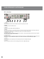
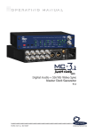
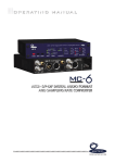
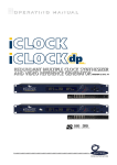
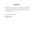
Operating Manual
MU TEC GmbH · Fo n 0049- ( 0) 30- 74 68 80- 0 · c o n t ac t @ m u t ec- n et . co m · www. m u t ec- n et . co m
Content
Safety Instructions...................................................................................................................................................................... 4
Warranty Regulations................................................................................................................................................................. 5
Introduction
General Description....................................................................................................................................................................... 6
MC-3+ Features............................................................................................................................................................................. 6
MC-3+ Applications....................................................................................................................................................................... 6
Peripheral MUTEC Products........................................................................................................................................................... 7
Product Registration for Warranty and Support............................................................................................................................. 7
Installation
Content of the Box......................................................................................................................................................................... 8
Placing the Device.......................................................................................................................................................................... 8
Wiring the Interfaces...................................................................................................................................................................... 8
General Recommendations for Interface Wirings & Cables............................................................................................................ 9
Control Elements and Terminals
MC-3+ Front Panel...................................................................................................................................................................... 10
MC-3+ Rear Panel....................................................................................................................................................................... 11
Operation
General System Operation........................................................................................................................................................... 12
Operation of the MC-3+.............................................................................................................................................................. 12
Status Information....................................................................................................................................................................... 16
Generic Functions........................................................................................................................................................................ 17
Appendix
Pin Assignment of the Connectors............................................................................................................................................... 18
Switching off the Termination of the Word Clock Input................................................................................................................ 18
Technical Data.............................................................................................................................................................................. 20
Generatable Word Clock (WCLK) Frequencies.............................................................................................................................. 21
Generatable AES11 & S/P-DIF blank frame Frequencies............................................................................................................... 21
3
Safety Instructions
General Instructions
To reduce the risk of fire or electrical shock, do not expose this appliance to rain or moisture,
direct sunlight or excessive heat from sources such as radiators or spotlights. No user serviceable parts are inside. Repair and maintenance must be carried out by qualified personnel authorized by MUTEC GmbH! The unit has been designed for operation in a standard domestic
environment. Do NOT expose the unit and its accessories to rain, moisture, direct sunlight or
excessive heat produced by such heat sources as radiators or spotlights! The free flow of air
inside and around the unit must always be ensured.
Initial Operation
Prior to the initial operation of the unit, the appliance, its accessories and packaging must
be inspected for any signs of physical damage that may have occurred during transit. If the
unit has been damaged mechanically or if liquids have been spilled inside the enclosure, the
appliance may not be connected to the mains or must be disconnected from the mains immediately! If the unit is damaged, please do NOT return it to MUTEC GmbH, but notify your
dealer and the shipping company immediately, otherwise claims for damage or replacement
may not be granted.
If the device is left in a low-temperature environment for a long time and then is moved to
a room-temperature environment, condensation may occur on the inside and the exterior.
To avoid short-circuits and flashovers, be sure to wait one or two hours before putting the
device into operation.
Power Supply
The device contains a self-adapting wide-range power supply supporting the majority
of global standard line voltages within a range of 90…250 V, with no need for making
adjustments. Make sure that your line-voltage source provides a supply voltage within the
specified range. In addition, make sure that the device is properly grounded via the local
electric installation.
Please use the enclosed power cord (see packaging) to connect the unit to the mains. Switch
the unit off before you attempt to connect it to the mains. Connect the power cord to the
unit, then to a standard 3-pin mains outlet. To draw the power cord, never pull on the cable
but on the mains plug!
The unit must be grounded during operation!
For information on the power-inlet wiring, refer to the »Wiring of connectors« section in the
appendix. Disconnect the device from the mains when not using it for an extended period!
Trademarks
MUTEC GmbH assumes no liability for any incorrect information given in this manual. Please
note that all software/hardware product names are registered trademarks of their respective
owners. No part of this manual may be reproduced, copied or converted to a machine-readable form or electronical media without a written permission of MUTEC GmbH. We reserve the
right to change or improve our products without notice. © MUTEC GmbH 2013
4
C A U T I O N
R I S K
O F
ELECTRICAL SHOCK!
!
This symbol, a flash of lightning inside a triangle,
alerts you to the presence of uninsulated dangerous
voltage inside the enclosure - voltage that may be
sufficient to constitute a risk of shock.
!
This symbol, an exclamation mark inside a triangle,
alerts you to important operating or safety instructions in this manual.
Declaration of Conformity
We herewith confirm that the product complies with the
European Commission’s standards on electromagnetic
compatibility.
Interference emission: Resistance to interference: EN 50081-1, 1992
EN 50082-1, 1992
Presupposed as operation condition is that all clock outputs are
connected with high-quality and good shielded BNC 75 ohms
cable.
Warranty Regulations
§1 Warranty
MUTEC GmbH warrants the flawless performance of this product to the original buyer for a period of two (2) years from the date of purchase. If any failure
occurs within the specified warranty period that is caused by defects in material and/or workmanship, MUTEC GmbH shall either repair or replace the product
free of charge within 90 days. The purchaser is not entitled to claim an inspection of the device free of charge during the warranty period. If the warranty claim
proves to be justified, the product will be returned freight prepaid by MUTEC GmbH within Germany. Outside Germany, the product will be returned with the
additional international freight charges payable by the customer. Warranty claims other than those indicated above are expressly excluded.
§2 Warranty Transferability
This warranty is extended exclusively to the original buyer who bought the product from a MUTEC GmbH specialized dealer or distributor, and is not transferable to anyone who may subsequently purchase this product. No other person (retail dealer, distributor, etc.) shall be entitled to give any warranty promise on
behalf of MUTEC GmbH.
§3 Waranty Regulations
The return of the completed registration card, or online registration on one of the websites specified below, is a condition of warranty. Failing to register the
device before returning it for repair will void the extended warranty.
The serial number on the returned device must match the one stated on the registration card or entered during online registration. Otherwise, the device
will be returned to the sender at the sender’s expense.
Any returned device must be accompanied by a detailed error description and a copy of the original sales receipt issued by a MUTEC dealer or distributor.
The device must be returned free of shipping expenses and in the original package, if possible; otherwise, the sender has to provide comparably protective
packaging.
The sender is fully responsible for any damage or loss of the product when shipping it to MUTEC GmbH.
§4 Limitation of Warranty
Damages caused by the following conditions are not covered by this warranty:
Damages caused by every kind of normal wear and tear (e.g. displays, LEDs, potentiometers, faders, switches, buttons, connecting elements, printed
labels, cover glasses, cover prints, and similar parts).
Functional failure of the product caused by improper installation (please observe CMOS components handling instructions!), neglect or misuse of the product, e.g. failure to operate the unit in compliance with the instructions given in the user or service manuals.
Damage caused by any form of external mechanical impact or modification.
Damage caused by the user’s failure to connect and operate the unit in compliance with local safety regulations.
Damage caused by force majeure (fire, explosion, flood, lightning, war, vandalism, etc.).
Consequential damages or defects in products from other manufacturers as well as any costs resulting from a loss of production.
Repairs carried out by personnel which is not authorized from MUTEC GmH
§5 Repairs
To obtain warranty service, the buyer must call or write to MUTEC GmbH before returning the unit. All inquiries must be accompanied by a description of
the problem and the original buyer’s invoice. Devices shipped to MUTEC GmbH for repair without prior notice will be returned to the sender at the sender’s
expense. In case of a functional failure please contact:
MUTEC Gesellschaft fuer Systementwicklung und Komponentenvertrieb mbH
Siekeweg 6/8 • 12309 Berlin • Germany • Fon 030-746880-0 • Fax 030-746880-99 • [email protected] • www.mutec-net.com
5
Introduction
Thank you very much for buying the MC-3+ Smart Clock, a Synchronizable Digital Audio Master Clock Generator, from MUTEC!
General Description
The new MUTEC MC-3+ Smart Clock is especially designed to improve the acoustical quality of digital audio devices in two
ways: At first by clocking external devices with ultra-low jitter Word Clock signals and secondly by aggressively re-clocking
incoming digital audio signals. Therefore, we have developed a totally new clocking technology, which we are calling the
»MUTEC 1G-Clock«. That means in practice, we are running – for the first time in the audio industry – an audio clock synthesis
process with a basis clock rate in the gigahertz area! Together with new ultra-low noise power supplies and new PCB design
rules aligned to high-speed communication technologies, the MUTEC 1G-Clock brings jitter and electrical noise down to unique
low levels, which leads to unprecedented transparency in your audio recordings.
Also working as a clock distributor and unlike other products, the MC-3+ effectively regenerates incoming clock signals to
higher purity as the signal source. Thus, the MC-3+ enables to improve already existing clock systems and helps to raise the
standard of sound reproduction in every studio environment.
Additionally, the MC-3+ Smart Clock locks to so-called atomic clocks or GPS receivers to raise its timing accuracy to the
highest possible level. For use during live events or in mobile trucks, the MC-3+ features an anytime fail-safe clock generation
in every operation mode. Entering the hold-over mode and re-synchronization of returning clock references is carried out so
smoothly that live recordings surely will not affected.
The new MUTEC MC-3+ Smart Clock and its unique 1G-Clock Technology add with most aggressive jitter reduction a significant
improvement in sound to most studio set-ups, while ensuring flawless synchronization of connected devices at any time!
MC-3+ Features
Incorporates MUTEC’s unique 1G-Clock Technology for lowest jitter possible
Improves audiophile quality of any connected digital audio device
Re-clocks digital audio most aggressively
Offers unique externally-referenced audio re-clocking
Raises clearly audible the sound quality of most DA converters
Eliminates digital “Clicks and Pops”
Enhances existing master clocks
Digitally-compensated clock accuracy for highest precision of the generated clocks
Locks to 10.0 MHz clock references of so-called Atomic clocks or GPS receivers
Outputs clock signals fail-safe in any state of operation
Generates Word Clocks, Super Clocks, AES3 + S/P-DIF blanks simultaneously
Converts between AES3 and S/P-DIF as well as between AES11 and Word Clock
New-designed, simple user interface
Front panel lock-out for preventing misuse
Rack-space-saving 9.5“ housing
Built-in, international power supply
Available with aluminum- or black-colored front panel
MC-3+ Applications
Audiophile sound improvement of digital audio devices
Elimination of »clicks and pops« in audio recordings
Enhancing and stabilization of existing clock chains
Stellate, ultra-low jitter clock signal supply
Addition of redundancy to clock chains in use
6
Introduction
Increase of clock signal reliability during live events
Multiple clock rate synchronization
Peripheral MUTEC Products
USB Interfaces
MC-1.2
The MC-1.2 is a high-performance USB audio interface which converts between USB, AES3, AES3id and S/P-DIF signals. It
enables for the first time bi-directional conversions between USB audio streams, AES3, AES3id and S/P-DIF signals.
Signal Distribution Amplifiers
MC-2
The MC-2 is a high-performance digital audio and reference sync signal distribution amplifier for AES3/11 and AES3/11id
signals. The unit distributes and converts between the mentioned AES signals and interface standards.
MC-7
The MC-7 is a flexible, high-performance 8-channel Word Clock distribution amplifier and audio clock converter.
Format and Sampling Rate Converters
MC-4
The MC-4 is a high-performance digital audio multichannel format and sampling rate converter for ADATTM, AES3 and S/P-DIF.
MC-6
The MC-6 is a high-performance digital audio dual channel format converter for AES3, AES3id and S/P-DIF.
MC-8 + MC-8.1
The MC-8 and MC-8.1 are 8 channel, high-performance digital audio and sampling rate converters for AES3 and AES3id.
Accessories
Optical cables in different lenghts from 0.5 m to 20 m for S/P-DIF and ADATTM transfers.
MW-02/19, Mounting plate to install two MC products side by side into one unit of a 19” rack.
MW-03/19, Set of two rack mounting angles to install one MC product on the rear side of a 19” rack.
MW-05/19, Set of two rack mounting angles to install one MC product frontally into one unit of a 19” rack.
For all peripheral products please have a look on our website:
www.mutec-net.com
Product Registration for Warranty and Support
We ask you to be so kind to register your MUTEC product through our website immediately after buying. This ensures full
warranty services over a period of two years after purchasing the product. More-over, for all registered products we offer to our
customers technical support. We also will inform you about product updates and new products which may of interest for you
(on voluntary base, of course).
Please regsiter your product at:
www.mutec-net.com > Service > Product Registration
Or for direct access type in the following URL into your browser:
http://www.mutec-net.com/produktregistrierung.php?lng=en
7
Installation
Content of the Box
Your MC-3+ was packed carefully. Nevertheless we recommend to check the content directly after opening the package:
1 x MC-3+
1 x Power cable
1 x USB cable
1 x Manual
If there are any damages visible, please refer to Safety Instructions and Warranty Regulations for further details.
Placing the Device
The unit should be set up as closely as possible to the devices to which it will be connected with to avoid excessive cable
lengths. The four custom-designed case feets include a rubber ring to protect the ground’s surface from being damaged.
The device can be mounted into a standard 19“ rack and will require one unit. Therefore, we offer an optional rack mounting
kit, called MW-05/19. This includes two rack angles which need to be screwed at each side of the device‘s case. Before mounting the device into a 19“ rack, please unscrew the four rubber feets with a suitable screwer. Install the device so that one unit
of rack space is left free both above and below the device to allow for sufficient ventilation! Additional slide-in rails on the
rack inside are recommended for safe installation. This will also avoid long-term mechanical deformation of the housing.
Attention
Before installing the unit the section Safety Instructions located at the beginning of this manual should be read carefully!
Never expose the device and accessories to rain, moisture, direct sunlight, or excessive heat produced by radiators, heaters, or
spot lights! Sufficient air circulation in the environment of the device must be ensured!
Wiring the Interfaces
Word Clock
To allow for the synchronization of signals, the interfaces of all devices involved must be properly connected to each other to
ensure a logical signal flow. Always be sure to connect the Word Clock output(s) to the corresponding input(s) of the device(s)
you wish to synchronize. Cable lengths should be kept as short as possible to minimize signal losses and/or interferences!
For the transmission of Word Clock signals, unsymmetrical cables with a impedance of 75 Ω and BNC connectors on both ends
are used. Typically, such cables are marked with »RG-59U, RG59B/U«.
Additionally, make sure that the Word Clock input(s) has/have got a 75 Ω terminating resistor! Most Word Clock inputs allow
for enabling/disabling the termination with a so-called »termination-switch«, which may be located on the outside or inside of
the device.
AES/EBU
Connect the AES/EBU interfaces with the help of balanced electrical cables equipped with XLR connectors on both ends. The specifications stipulate a specific cable impedance of 110Ω (ask your retailer for a confirmation of this value when buying the cables).
S/P-DIF
Two coaxial S/P-DIF interfaces are available, one based on standard RCA, the other one based on BNC connectors. Connect
these interfaces with help of unbalanced electrical cables equipped with RCA respectively BNC connectors on both ends. The
specifications stipulate a specific cable impedance of 75 Ω for both. Ask your retailer for a confirmation of this value when
buying the cables.
Connect the optical S/P-DIF interface with the help of Toshiba TOSLINK™ compliant optical fiber cables. You can use both
plastic and glass fiber-based cables.
8
Installation
For devices which have no termination of the Word Clock input, e.g. RME Hammerfall with Word Clock i/o, Alesis BRC or
M-Audio ProFire Light bridge, you can use an additional BNC-T piece to terminate the input. Plug the T piece with its center
connector into the input of the receiving device. Then, connect the cable coming from the Word Clock output to one of the
lateral connectors, and the other connector of the BNC-T piece to a 75 Ω resistor forming the BNC termination.
Basically, you should avoid »looping through« Word Clock leads by means of passive BNC-T pieces to preserve the signal quality, as level drops will be the result. If there is no other way to wire your set-up, please make sure that all Word Clock inputs
(except for the last device in the chain) have their terminations disabled! In a serial Word Clock chain only the last clock input
should have a termination! Never connect more than three devices in series to one output!
General Recommendations for Interface Wirings & Cables
Word Clock
If a cable with a different impedance than 75 Ω is used, a dramatic deterioration of the signal quality is the result! In this case,
the sound quality and synchronization of all devices involved can be impaired.
It is imperative that the lengths of all cables connected are largely the same to ensure that all devices will be synchronized in
phase (exception: cable tolerances).
We recommend using high-grade cables with a good shielding. A length of max. 10 meters (approx. 30 feets) should not be
exceeded!
AES/EBU & S/P-DIF Interconnections
When working with XLR-based AES3/-11 or RCA-based S/P-DIF audio signals at high sampling rates , well-shielded electrical
cables are mandatory to avoid increased radiation! Standard cables are normally useable for sampling rates up to 50.0kHz.
When interconnecting the optical S/P-DIF interfaces with plastic fiber cables, lengths of 10 meters should not be exceeded,
to ensure reliable transmission of your digital audio signals. Glass fiber cables may transfer data reliably even over greater
distances while keeping the signal’s performance on a much higher level than plastic fibre cables can do during transmission!
Information
MUTEC offers optical cables of various lengths that have been specifically tested for the transmission of ADAT™ and S/P-DIF
signals. Ask your local dealer for such cables!
9
Control Elements and Terminals
MC-3+ Front Panel
1
2
3
4
5
6
7
7
7
1 »POWER«
This red LED lights up when the unit is switched on with the rear panel power switch.
2 »MENU«
Use this key to access the different menus.
3 »SELECT«
Use this key to select a function within a specific menu.
4 »MODE«
This function menu allows to select the clock references for internal and external synchronization as well as the reference for
externally-referenced digital audio re-clocking. All three LED rows act in functional dependence.
5 »REFERENCE INTERNAL + 10.0M«
This function menu allows to select the clock references for internal or external synchronization and the reference for synchronous and asynchronous digital audio re-clocking.
6 »CLOCK MULTIPLIERS«
This function menu lets you determine the factor by which the basis clock rate is multiplied additionally. Settings can be made
individually for every pair of Word Clock outputs (»1-3«) as well as for the AES3 (»5«) and S/P-DIF (»4«) outputs.
7 »STATUS«
This menu indicates various signal status of the incoming reference clock or digital audio signal.
8 »CLOCK IN«
This menu indicates the clock rates of the incoming reference clock or digital audio signal.
10
Control Elements and Terminals
MC-3+ Rear Panel
1
2
3
4
5
6
7
1 »WCLK OUT 1– 3«
These 3 pairs of Word Clock outputs transfer all standard Word Clock rates and Word Clock × 256 for older digidesign ProTools™ systems. Their numbering is aligned to the apropriate menus on the front panel. The individual BNC connectors are
pairwise marked as »A« and »B«, which allows for, e.g. simple documentation of the connected devices. The impedances of all
connectors are 75 Ω (BNC connectors, female).
2 »S/P-DIF OUT 4«
These two S/P-DIF outputs, available as optical and coaxial interfaces, transmit an optical (»OP«) and unbalanced electrical
(»CO«) S/P-DIF digital audio or blank frame signal in compliance with the IEC 60958 standard. The coaxial interface impedance
is 75 Ω. (RCA connector), the optical interface offers a Toshiba ToslinkTM connector, EIAJ standard. Its numbering is aligned to
the apropriate menu on the front panel.
3 »AES3/11 OUT 5«
This AES/EBU output transmits a transformer-balanced electrical digital audio or blank-frame signal in compliance with AES31997 (revision of 1992) or AES11-2003 (revision of 1997). Its numbering is aligned to the apropriate menu on the front panel.
The output impedance is 110 Ω (XLR connector, male).
4 »AES3/11 IN«
This AES/EBU input receives a balanced electrical digital audio or blank-frame signal in compliance with AES3-1997 (revision of
1992) or AES11-2003 (revision of 1997). The input impedance is 110 Ω (XLR connector, female).
5 »S/P-DIF IN«
These two S/P-DIF inputs, available with optical (»OP«) and coaxial (»CO«) interfaces, receive an optical and an unbalanced
electrical S/P-DIF digital audio or blank frame signal in compliance with the IEC 60958 standard. The coaxial interface impedance is 75 Ω. (RCA connector), the optical interface offers a Toshiba ToslinkTM connector, EIAJ standard.
6 »WCLK + 10.0M IN«
This input can receive a Word Clock, a Word Clock × 256 as well as a 10.0 MHz reference clock signal. The impedance of the
connector is 75 Ω (BNC connector, female).
8 »MAINS IN«, Power Switch + Mains connector (IEC)
This is the main switch for switching the device on and off. Connect the supplied IEC power cable to the device‘s mains connector. Make sure that the power switch is turned off before connecting the device to your power source finally. Line voltages
within the range of 90…260 V with a frequency of 50 or 60 Hz can be applied. The internal power supply will automatically
make all necessary adjustments.
Read the Safety Instructions at the beginning of this manual!
Attention
For detailed specifications of all interfaces, please refer to the »Pin Assignment of the Connectors« and »Technical Data«
sections in the Appendix chapter.
11
Operation
General System Operation
Operating the MC-3+ is very easy! The device is fully operated using the two keys on the front panel.
»MENU« Key
Pressing the »MENU« key toggles between different basic function menus, usually between the vertical LED rows.
»SELECT« Key
Pressing the »SELECT« key activates individual functions within one menu by toggling between the LEDs of one vertical LED
row.
First press on »MENU« or »SELECT« key enables the last selected function within the last selected menu. The appropriate LED
starts flashing. Every press on »SELECT« key will select a new function within the menu and the LED flashes accordingly. After
a period of approx. 4 seconds the LED of the selected function stops flashing and the function is activated.
The »STATUS« and »CLOCK IN« menus are not accessible for adjustments. For further descriptions see next page under Status
Information.
Operation of the MC-3+
Main Function Menus
The three main function menus offer access to the whole functionality of your MC-3+ Smart Clock.
The »MODE« menu allows to select for the general operation mode of the MC-3+. It has to be selected first. The factory default is set to »INTERNAL«.
The »REFERENCE« menu including the sub menu »INTERNAL + 10.0M« allow to select all external acceptable references, the
references for synchronous and externally-referenced audio re-clocking as well as the internal clock generator. The factory
default is set to »INTERNAL« with 44.1 kHz.
Within the »CLOCK MULTIPLIERS« menu you can select additional multipliers, individually for each pair of Word Clock and the
digital audio outputs. Their numberings are assigned to the output numbers on the rear. Select the prefered output with the
»MENU« key and the needed multiply factor by pressing the »SELECT« key accordingly. The factory default is set to x 1.
The menus »STATUS« and »CLOCK IN« are for control of the MC-3+‘s operation status only. They are not accessable for adjustments.
Attention
Shut-Down of Outputs – All digital audio outputs are shut-down during function selection! After a function is finally selected
and the corresponding LED lights constantly again, the digital audio outputs are activated for signal transfer.
User Settings Remain – All user-specific function settings are available furthermore when power is restored.
General Operation Procedure
The menu of your MC-3+ is strictly organized aligned to general handling procedures when inserting the MC-3+ into your
studio set-up. Thus, you can split up all of the necessary adjustments in three steps only, which leads to the following three
questions for the basic operation of your MC-3+:
12
Operation
1) Which operation mode is basically needed? → »MODE«
Should my MC-3+ work as clock generator (»INTERNAL«), as clock distributor (»EXTERNAL«) or as audio
signal re-clocker (»RE-CLOCK«)?
INTERNAL
EXTERNAL
RE-CLOCK
MODE
2) Which reference do I need for my clocking application? → »REFERENCE«
WCLK
32.0
10.0M
44.1
S/P-DIF op
48.0
S/P-DIF co
88.2
176.4
192.0
AES3/11
REFERENCE
96.0
INTERNAL + 10.0M
3) Do I need different clock rates at the same time? → »CLOCK MULTIPLIERS«
x 1
1
2
3
4
5
x 2
x 4
x 256
CLOCK MULTIPLIERS
After these general decisions are made, your MC-3+ is configured for optimal operation in your set-up. Due to the fact that the
system monitors for useful function combinations, maloperation is not possible.
So, let‘s have a look to the individual functions.
Selecting Modes
This setting example shows the MC-3+ locked to its internal ultra-low jitter clock base generating output clocks of 44.1 kHz at
any available output. This is the factory default setting.
1
WCLK
32.0
EXTERNAL
10.0M
44.1
RE-CLOCK
S/P-DIF op
48.0
x 4
S/P-DIF co
88.2
x 256
MODE
AES3/11
REFERENCE
96.0
176.4
192.0
2
3
4
5
x 1
INTERNAL
x 2
INTERNAL + 10.0M
CLOCK MULTIPLIERS
13
Operation
There are three basic operation modes of your MC-3+ Smart Clock:
»INTERNAL«
The MC-3+ runs as a clock generator and is locked to its internal ultra-low jitter master clock. The basis clock rate for all outputs is selected in the »REFERENCE« menu under »INTERNAL + 10.0M« (see next page).
»EXTERNAL«
The MC-3+ is locked to an externally applied reference signal, which can be a Word Clock, a 10.0 MHz reference from a so-called atomic clock or GPS receiver and an AES3/11 or S/P-DIF digital audio signal, selected in the »REFERENCE« menu.
»RE-CLOCK«
The MC-3+ allows to receive digital audio signals of the AES3 or S/P-DIF format (selected in the »REFERENCE« menu) especially for re-clocking to improve their acoustical quality. There are two audio re-clocking modes available, one based on the internal clock oscillator (»RE-CLOCK« & »INTERNAL«) and one working with an externally applied clock reference (»RE-CLOCK« &
»EXTERNAL«).
»RE-CLOCK« & »INTERNAL«
With first selection of the »RE-CLOCK« mode the »INTERNAL« and »RE-CLOCK« LEDs start lighting and show that re-clocking
based on the internal clock oscillator is active. Under »REFERENCE« the first available digital audio input »S/P-DIF op« is selected automatically as default. Press the »MENU« key once and you enter the »REFERENCE« menu. Here press repeatedly the
»SELECT« key to select the desired digital audio input. The applied digital audio signal will be re-clocked with a new generated
ultra-low jitter clock signal, embedded in the outgoing audio signal with the incoming audio signal‘s sampling rate.
»RE-CLOCK« & »EXTERNAL«
This is a very special function only available in your MC-3+ Smart Clock! After selection of the first re-clocking mode press the
»SELECT« key one time again and the »EXTERNAL« and »RE-CLOCK« LEDs light and show that re-clocking based on an externally applied clock reference is active. Under »REFERENCE« »WCLK« and the first available digital audio input »S/P-DIF op«
are selected automatically as default. Press the »MENU« key once and you enter the »REFERENCE« menu. By pressing the
»SELECT« key repeatedly, you can select one of the three available digital audio inputs together with one of two possible
external clock references: WCLK and 10.0M. Therefore, every selected audio input is automatically combined with one of the
two external references:
Selected Audio Input + WCLK
Selected Audio Input + 10.0M
Selecting one of these externally-referenced re-clocking options enables to re-clock a digital audio signal with an external
clock reference of a different master clock device. E.g., when selecting your desired audio input + »WCLK«, you must feed in
at the Word Clock input an additional Word Clock reference signal with a clock rate between 32.0 kHz and 192.0 kHz. When
selecting your desired audio input + »10.0M«, the Word Clock input accepts a 10.0 MHz reference signal from e.g. a so-called
Atomic Clock or GPS receiver. In both ways, the outgoing digital audio and Word Clock signals have got the same basis clock
rate like the incoming digital audio source.
In the »CLOCK IN» menu the clock rate of the incoming digital audio signal is displayed and with help of the »CLOCK MULTImenu the Word Clock output signals can be multiplied as described in the section »Selecting Clock Multipliers«.
PLIERS«
Attention
Digital Audio Format Conversion – When running the MC-3+ in the »RE-CLOCK« mode and applying a digital audio signal of
AES3 or S/P-DIF format as reference, all digital audio outputs will transmit the source signal. The signals at the outputs which
are not of same format as the reference signal will be format converted in realtime aligned to the AES3 – 1992/2003 and
IEC 60958 digital audio format standards. Thus, your MC-3+ Smart Clock works also as digital audio format converter for you!
14
Operation
Selecting References
Selection of references is mainly used when the MC-3+ is set under »MODE« to »EXTERNAL« or »RE-CLOCK«.
1
WCLK
32.0
EXTERNAL
10.0M
44.1
RE-CLOCK
S/P-DIF op
48.0
x 4
S/P-DIF co
88.2
x 256
MODE
AES3/11
REFERENCE
96.0
176.4
192.0
2
3
4
5
x 1
INTERNAL
x 2
INTERNAL + 10.0M
CLOCK MULTIPLIERS
The above setting example shows the MC-3+ locked to an external Word Clock signal. Its clock rate is then displayed in the
»CLOCK IN« menu on the right hand side of the front panel. Within the »REFERENCE« menu you can select the other available
inputs by presssing the »SELECT« key repeatedly. The example shows furthermore, that in the »CLOCK MULTIPLIERS« menu
multiplication factors are set for the indivdual outputs as follows:
Word Clock output pair 1: Reference clock x 1
Word Clock output pair 2: Reference clock x 4
Word Clock output pair 3: Reference clock x 2
S/P-DIF output 4: Reference clock x 2
AES3/11 output 5: Reference clock x 1
When working in the »INTERNAL« mode, only the LED bar marked with »INTERNAL + 10.0M« is available for selecting the
basis clock rate of all outputs. There are seven different audio-related basis clock rates between 32.0 kHz and 192.0 kHz
selectable by pressing the »SELECT« key repeatedly, indecated by one or two LEDs.
Selecting 10.0M as Clock Reference
When stepping through the »REFERENCE« menu and selecting »10.0M« as reference, simultaneously the first LED of the »INTERNAL + 10.0M« sub menu starts lighting and you can select with the »SELECT« key one of the seven clock rates provided by
the internal ultra-low jitter clock generator. The outgoing clock signals are now of the selected clock rate, but frequency-locked
to the externally applied 10.0 MHz reference signal. Also in that mode, clock multipliers can be adjusted freely, as mentioned
in the »Selecting Clock Multipliers« section.
Further Setting Examples
1
WCLK
32.0
EXTERNAL
10.0M
44.1
RE-CLOCK
S/P-DIF op
48.0
x 4
S/P-DIF co
88.2
x 256
MODE
AES3/11
REFERENCE
176.4
192.0
32.0
EXTERNAL
10.0M
44.1
RE-CLOCK
S/P-DIF op
48.0
x 4
S/P-DIF co
88.2
x 256
MODE
REFERENCE
192.0
2
3
4
5
x 2
INTERNAL + 10.0M
A 10.0 MHz clock signal is applied as reference and the basis
clock of all outputs is set to 48.0 kHz. The outputs provide
different multiples of the basis clock rate due to the adjustments
of the clock multipliers. All four red LEDs in the »CLOCK IN« area
light to show that a 10.0 MHz reference comes in.
CLOCK MULTIPLIERS
1
WCLK
AES3/11
5
x 1
INTERNAL
176.4
4
x 2
INTERNAL + 10.0M
96.0
3
x 1
INTERNAL
96.0
2
A coaxial S/P-DIF digital audio signal is applied as reference. All
outputs provide their clock rates aligned to the selected multiplication factors. The S/P-DIF (»4«) and AES3/11 (»5«) outputs
supply blank frame signals.
CLOCK MULTIPLIERS
15
Operation
1
WCLK
32.0
EXTERNAL
10.0M
44.1
RE-CLOCK
S/P-DIF op
48.0
x 4
S/P-DIF co
88.2
x 256
MODE
AES3/11
REFERENCE
96.0
176.4
192.0
32.0
EXTERNAL
10.0M
44.1
RE-CLOCK
S/P-DIF op
48.0
x 4
S/P-DIF co
88.2
x 256
MODE
REFERENCE
192.0
5
2
3
4
5
x 2
INTERNAL + 10.0M
An optical S/P-DIF digital audio signal is re-clocked. All outputs
provide their signals on the same clock rate like this one of the
incoming optical S/P-DIF digital audio signal.
CLOCK MULTIPLIERS
1
WCLK
AES3/11
4
x 1
INTERNAL
176.4
3
x 2
INTERNAL + 10.0M
96.0
2
x 1
INTERNAL
An AES3 signal is externally-referenced and re-clocked with an
additional Word Clock signal. All outputs provide their signals
with same clock rate like this one of the incoming AES3 digital
audio signal, except the Word Clock output 3 is set to output the
double clock rate of the reference signal.
CLOCK MULTIPLIERS
Selecting Clock Multipliers
Pressing the »MENU« key changes from the »REFERENCE» to the »CLOCK MULTIPLIERS« menu. Here you can select for
every pair of Word Clock and the digital audio outputs individual clock rate multiplication factors of ×1, ×2, ×4 and ×256 by
pressing the »SELECT« key repeatedly. The multiplication factors refer always to the basis clock rate of the incoming reference
signal or the clock rate selected of the internal ultra-low-jitter clock generator (»INTERNAL + 10.0M«). Thus, dependently of
the incoming or selected basis clock rate, the MC-3+ covers a range of audio related clock rates from 32.0 kHz up to 768.0 kHz
plus the two so-called Super Clocks.
The setting »×256«, or so-called Super Clock, is only available for the three pairs of Word Clock outputs. It transmits either a
clock rate of 11,289.6 MHz (44.1 kHz × 256) or 12,288.0 MHz (48.0 kHz × 256). The system analysis in any way the basis clock
rate of the incoming or the generated reference clock signal, 44.1 kHz or 48.0 kHz, and outputs the corresponding Word Clock
×256 for use with older digidesign ProToolsTM systems.
The multiplication of the digital audio outputs S/P-DIF (»4«) and AES3/11 (»5«) is limited to a maximum clock rate of
192.0kHz, regardless of the clock rate of the reference signal.
Attention
Multiplying Digital Audio Signals – When having a digital audio input selected as reference and setting the multiplication
factor to higher than »×1«, the MC-3+ outputs a blank frame signal only at the audio outputs. A sampling rate conversion of
the incoming digital audio signal is not carried out.
Status Information
The »STATUS« and »CLOCK IN« menus are for control of the MC-3+‘s operation status only. They are not accessable for adjustments with help of the keys.
STATUS
»LOCK«
This blue LED lights when the internal PLL circuit has detected the incoming clock reference signal as valid. If the reference
signal is unstable or lost, the »LOCK« LED does not light.
16
Operation
»HOLD«
This red LED lights when the external reference clock signal is interrupted or lost. The frequency synthesizer of the MC-3+ keeps generating all output signals continuously, based on the last incoming clock rate. Thus, your studio set-up receives non-interrupted clock supply, regardless if a valid external referecne signal is present, unstable or lost. Re-synchronization is carried
out without affecting any of the outputs signals critically.
»AUDIO«
This red LED lights when a valid AES3/11 or S/P-DIF optical or coaxial digital audio reference signal is detected at the corresponding input.
CLOCK IN
This area displays the clock rate of
the incoming clock or digital audio
reference signal. The following basis
reference clock rates are supported and
will be analyzed.
Supported Input Clock Rates at the WCLK IN
32.0 kHz
44.1 kHz
48.0 kHz
176.4 kHz
192.0 kHz
10.0 MHz
88.2 kHz
96.0 kHz
11,289.6 MHz 12,288.0 MHz
Generic Functions
There are two additional functions which influence the working of your whole MC-3+:
Front Panel lock out + LED shut down
When pressing both front panel keys together at one time, all LEDs will shut down except the »POWER« and »LOCK« LEDs.
Additionally, the functions of both keys are also blocked to prevent unauthorized operation, which is important during e.g. live
events.
During that state of operation, pressing only one of both keys let every appropriate LED light according the device‘s settings as
long as the key is pressed. Thus, you can check easily the device‘s settings without unlocking the device finally.
To reactivate the keys and the LEDs, please press both keys for apperox. four seconds until all LEDs light again.
Factory Reset
You can reset the operating system of your MC-3+ to the initial status by switching on the unit while pressing the »MENU«
key simultaneously.
17
Appendix
Pin Assignment of the Connectors
Mains
BNC Input/Output for
Word Clock, 10.0 MHz
Optical TOSLINK Input/Output
for S/P-DIF
3
1
2
1
1
2
1 Live, phase (brown; USA: black)
2 Protective earth (green/yellow; USA: green)
3 Neutral (blue; USA: white)
1 Signal
2Ground
AES/EBU, XLR, Input
for AES3/11
RCA, Input/Output
for S/P-DIF
AES/EBU, XLR, Output
for AES3/11
1 Optical signal
1
2
1 Audio signal
2 Audio ground
1
2
2
3
1
1 Ground
2 a conductor (hot / +)
3
1 Audio ground
2 a conductor (hot / +)
NOTE:
The RCA-based S/P-DIF
inputs and outputs are
not galvanically isolated,
due to IEC 60958.
Switching off the Termination of the Word Clock Input
Attention
Disconnect the unit from the mains before opening! Remount the aluminium cover thoroughly before you attempt to operate
the unit!
JP1
Jumper:
1
2
Jumper Position 2
= Termination
18
Free Pin:
When the MC-3+ Smart Clock is shipped, the BNC-based Word Clock
input connector is terminated internally with 75 Ω. Therefore, one
jumper is put on two pins - Position 2 - of the 3-pin socket JP1.
JP1
Appendix
When the MC-3+ Smart Clock is shipped, the BNC-based Word Clock input connector is
terminated internally with 75 Ω. Therefore, one jumper is put on two pins - Position 2 - of
the 3-pin socket JP1.
1
2
Jumper Position 1
= no Terminaltion
For additional information, please refer to page 11 under »Wiring the Interfaces – Word Clock«.
Inside View – Word Clock Termination
Word Clock
Input
S/P-DIF
Inputs
Termination
3-pin socket
JP1
MC-3+
Mainboard
PCB
19
XX XX
Appendix
Technical Data
Word Clock & 10.0 MHz Input (WCLK + 10.0M)
Interface
1 x BNC, 200 mV-7 V, unbalanced, input impedance 75 Ω (can be switched off, see Page 18/19)
Formats & Resolutions
Word Clock, Word Clock × 256, so-called »Super Clock«, 10.0 MHz
Supported Sampling Rates
32.0 kHz to 192.0 kHz, 10.0 MHz,
AES3 Audio Input (AES3/11 IN)
Interface
1 x XLR female, transformer balanced, input impedance 110 Ω, 200 mV–7.0 V
Format, Resolution
AES3-1992/2003, AES11-1997/2003, IEC 60958, 16–24 bits
Supported Sampling Rates
32.0 kHz to 192.0 kHz
S/P-DIF Optical Audio Input (S/P-DIF IN, OP)
Interface
1 x ToslinkTM, EIAJ RC-5720
Format, Resolution
IEC 60958, 16–24 bits
Supported Sampling Rates
32.0 kHz to 192.0 kHz
S/P-DIF RCA Audio Input (S/P-DIF IN, CO)
Interface
1 x Coaxial (RCA female), unbalanced, 0.5 –1.0 Vpp @ 75 Ω, output impedance 75 Ω
Format, Resolution
IEC 60958, 16–24 bits
Supported Sampling Rates
32.0 kHz to 192.0 kHz
Word Clock Output (WCLK OUT 1–3)
Interface
1 x BNC, 200 mV–7 V, unbalanced, input impedance 75 Ω
Format, Resolution
Word Clock, Word Clock × 256, so-called »Super Clock«
Supported Sampling Rates
32.0 kHz to 192.0 kHz
AES3/11 Output (AES3/11 OUT 5)
Interface
1 x XLR male, transformer balanced, 3.5Vpp @ 110Ω, output impedance 110 Ω, buffered
Format, Resolution
AES3-1992/2003, AES11-1997/2003, IEC 60958, 16–24 bits
Supported Sampling Rates
44.1 kHz to 192.0 kHz
S/P-DIF Optical Audio Output (S/P-DIF OUT 4, OP)
Interface
1 x ToslinkTM, EIAJ RC-5720
Format, Resolution
IEC 60958, 16–24 bits
Supported Sampling Rates
44.1 kHz to 192.0 kHz
S/P-DIF RCA Audio Output (S/P-DIF OUT 4, CO)
Interface
1 x Coaxial (RCA female), unbalanced, 0.5 Vpp @ 75 Ω, output impedance 75 Ω, buffered
Format, Resolution
IEC 60958, 16–24 bits
Supported Sampling Rates
44.1 kHz to 192.0 kHz
Signal Processing
Word Clock + AES11 conversion in every combination and direction
Digital Audio Format &
AES3 + AES11 + S/P-DIF (optical + coaxial) conversion in every combination and direction
Clock Signal Conversion
10.0 MHz to Word Clock and AES11 conversion
Digital audio re-clocking, internally- and externally-referenced
Frequency Synthesis & Reference Clock Specifications
Frequency Synthesis
MUTEC’s propritary 1G-Clock Technology based on highest-clocked DDS process
Oscillator Type
XO, digitally-compensated crystal oscillator
Clock Accuracy (shipped)
< ± 0.1 ppm
Clock Jitter
< 1 ps (RMS)
Operating Temperature
0 °C to + 50 °C
20
XX XX
Appendix
Power Supply
Type
Internal, switching power supply
Input Voltage
85 V – 264 V (automatic adjustment), 47 Hz – 440 Hz
Power Consumption
max. 10 W
System Unit Cover
Cover Size / Material / Color
196 x 42 x 156 mm w/o connectors (W x H x D), steel sheet 1mm, matte-black powder-coated
Front Panel Size / Material
198 x 44 x 4 mm (W x H x D), aluminum, aluminum- or black-colored
Weight
~ 1260 g
MC-3+ Smart Clock Order Information
Front aluminum-colored
Item no. 8015-100, EAN code: 4260342460542
Front black-colored
Item no. 8015-101, EAN code: 4260342460559
Generatable Word Clock (WCLK) Frequencies
WCLK BASIS
32.0 kHz
44.1 kHz
48.0 kHz
88.2 kHz
96.0 kHz
176.4 kHz
192.0 kHz
x1
32.0 kHz
44.1 kHz
48.0 kHz
88.2 kHz
96.0 kHz
176.4 kHz
192.0 kHz
x2
64.0 kHz
88.2 kHz
96.0 kHz
176.4 kHz
192.0 kHz
352.8 kHz
384.0 kHz
x4
128.0 kHz
176.4 kHz
192.0 kHz
352.8 kHz
384.0 kHz
705.6 kHz
768.0 kHz
x 256
–
11.2896 MHz
12.2880 MHz
–
–
–
–
Generatable AES11 & S/P-DIF blank frame Frequencies
WCLK BASIS
32.0 kHz
44.1 kHz
48.0 kHz
88.2 kHz
96.0 kHz
176.4 kHz
192.0 kHz
x1
32.0 kHz
44.1 kHz
48.0 kHz
88.2 kHz
96.0 kHz
176.4 kHz
192.0 kHz
x2
64.0 kHz
88.2 kHz
96.0 kHz
176.4 kHz
192.0 kHz
176.4 kHz
192.0 kHz
x4
128.0 kHz
176.4 kHz
192.0 kHz
176.4 kHz
192.0 kHz
176.4 kHz
192.0 kHz
21
MU TEC GmbH · Fo n 0049- ( 0) 30- 74 68 80- 0 · c o n t ac t @ m u t ec- n et . co m · www. m u t ec- n et . co m