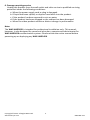
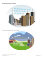
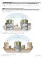
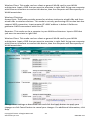
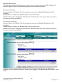
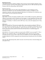
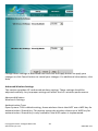
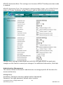
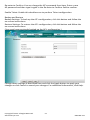
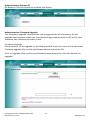
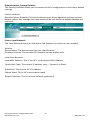
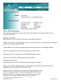
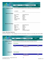
1
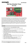
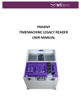
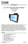
User Manual Outdoor LAN Access Point with 1W Amplifier WAP-ABG2458 FEATURES Dual Band 2.4GHz/5.8GHz Tri-Mode 802.11 a/b/g Point-to-Point/ Point-to-Multipoint Wireless Connectivity Watertight and Weatherproof 64 / 128 / 152-bit WEP Data Encryption AP, Bridge, Station, and Repeater Modes Hide SSID (AP Mode) DHCP Client/ Server MAC Address Filtering (AP Mode) Power Amplifier Upgradeable Web-based Configuration Power over Ethernet (PoE) Output Power 2W Please read the Manual before attempting to use this product. MD-A Disposal of Old Electrical & Electronic Equipment (Applicable in the European Union and other European countries with separate collection systems). This symbol on the product or on its packaging indicates that this product shall not be treated as household waste. Instead it shall be handed over to the applicable collection point for the recycling of electrical and electronic equipment. By ensuring this product is disposed of correctly, you will help prevent potential negative consequences for the environment and human health, which could otherwise be caused by inappropriate waste handling of this product. The recycling of materials will help to conserve natural resources. For more detailed information about recycling of this product, please contact your local city office, your household waste disposal service or the shop where you purchased the product. CAUTION 1. Handle this product with care Avoid any shock or bumping of the camera. Improper handling could damage the camera. 2. Requires a proper operating environment This camera is designed for indoor use. The allowable temperature range for operation of this camera is between -4°F ~ 122°F / -10C ~ 50C. 3. Check the power source voltage The power source voltage should be within the specified range. (Product must meet the specifications). 4. Objects and liquid entry Never push objects of any kind into this product as this may touch dangerous voltage points of short out parts that could result in a fire or electric shock. Never spill any kind of liquid on the product. 5. Servicing Do not attempt to service this product by yourself as opening or removing covers may expose you to dangerous voltage or other hazards. Refer all service to qualified servicing personnel. Copyright © 2012. All Rights Reserved. www.sentryus.com 2 R201204-V27 6. Damage requiring service Unplug this product from the wall outlet and refer service to qualified servicing personnel under the following conditions: a. When the power supply cord or plug is damaged. b. If liquid has been spilled, or objects have fallen into the product. c. If the product has been exposed to rain or water. d. If the product has been dropped or the cabinet has been damaged. e. When the video product exhibits a distinct change in performance. Note: The WAP-ABG2458 is intended for professional installation only. This manual, however, is also designed for personnel who plan, operate and administrate the WAP-ABG2458 communication system. Please review the entire manual before powering up or deploying any WAP-ABG2458. Copyright © 2012. All Rights Reserved. www.sentryus.com 3 R201204-V27 INDEX OVERVIEW …………………………………………………………………………………………………..………….. 5 PACKAGE CONTENTS …………………………………………………………………………..….……...……….. 5 APPLICATIONS ……………………………………………………………………………………………..……….. 6-7 OPERATION TYPES ………………………………………………………………………………….……….……….. 8 HARDWARE INSTALLATION …………………………………………………………………………..…….. 9-15 TYPICAL DEPLOYMENT IN A POINT-TO-POINT CONFIGURATION ……………………………… 15 SETTING THE BASE STATION UNIT (BU) ……………………………………………………..………. 15-22 SETTING THE REMOTE UNIT (RU) ………………………………………………………….…..……… 22-29 RUNNING TEST …………………………………………………………………………………..……….……. 29-34 MOUNTING LOCATION ……………………………………………………………………………..………. 35-37 SPECIFICATIONS ……………………………………………………………………………………………………… 37 LIMITED WARRANTY ……………………………………………………………………………..……………... 38 APPENDIX A: ACCESS POINT / BRIDGE CONFIGURATION …………………………………… 38-55 Copyright © 2012. All Rights Reserved. www.sentryus.com 4 R201204-V27 OVERVIEW The WAP-ABG2458 is a powerful answer for customers seeking a reliable high-speed wireless connectivity solution. It is a 2.4GHz (802.11 b/g ) and 5.8GHz (802.11a)-compliant Wireless Bridge/AP/AP Client, data delivers 1 to 54 Mbps data rates without the need for a license. WAP-ABG2458 can operate as a point-to-point or a point-to-multipoint bridge to link networks in different buildings. It is particularly suited for financial banks, campus, store merchants and small business owners to create wireless backbone networks. System privacy is inherent through the MAC WEP based mutual authentication functionality by preventing unauthorized intrusion to the radio link. The WAP-ABG2458 is designed for outdoor environments. With lift-cover watertight housing, this is a robust Bridge/AP/AP Client, and uniquely designed that Antenna to integrate with housing. Supplying the power and Ethernet connectivity concurrently via a single Ethernet cable, the power over Ethernet (PoE) technology makes quick outdoor installation. WAP-ABG2458 achieves rapid Return On Investment (ROI) for inter-building connection compared to T1 leased line with high capacity and high data throughput. PACKAGE CONTENTS One (1) Outdoor Unit Three (3) Mounting Brackets Four (4) Long Screws Twelve (12) Washers Eight (8) Small Screws Twenty Four (24) Small Washers One (1) DC Injector One (1) 48V DC Power Adapter One (1) Installation CD One (1) User Manual For any returns, please include all components listed above with original packaging in Resalable Condition. Absolutely No Returns will be accepted if any component is missing/damaged. Copyright © 2012. All Rights Reserved. www.sentryus.com 5 R201204-V27 APPLICATIONS Central Office to Branch Office(s) Connection Medical Hospitals to Medical Hospitals Wireless Connection Copyright © 2012. All Rights Reserved. www.sentryus.com 6 R201204-V27 Building to Building Connection Connection between City and Suburb Copyright © 2012. All Rights Reserved. www.sentryus.com 7 R201204-V27 OPERATION TYPES There are two different modes in which you can set up the WAP-ABG2458 in the building-to-building wireless network: Point to Point mode, and Point to Multipoint mode. Mode 1: Point-to-Point Connectivity (PTP Mode) This is the simplest network configuration in which several computers equipped with the PC cards or client bridges that form a wireless network whenever they are within range of one another. Mode 2: Point to Multipoint Mode (PTMP Mode) Copyright © 2012. All Rights Reserved. www.sentryus.com 8 R201204-V27 HARDWARE INSTALLATION HARDWARE DESCRIPTION Outdoor Unit: A. Two layers silica gel: having double-waterproof B. EMI prevent wire: To avoid electromagnetic interference C. Nylon cable gland:IP68; Working Temp:-40°C~100°C D. Half-screw: Not to fall E. Panel Antenna:17 dBi gain; SMA connector F. Access Point/Bridge: IEEE 802.11a -compliant G. Power over Ethernet (POE) Splitter set: Output 5V DC / 3A H. Mounting kit: Mounting Bracket on Mast with /U-bolts * LED on the AP/Bride description: On the AP/Bridge there are LED lights that inform you of the AP/Bridge’s current status. Below is an explanation of each LED. Copyright © 2012. All Rights Reserved. www.sentryus.com 9 R201204-V27 The Power LED lights up and will keep while the AP is powered on. Power When the AP goes through its self-diagnostic mode during every boot-up, this LED will flash. When the diagnostic is complete, the LED will be lit continuously. 11a 11b/g LAN The 11a LED flashes when there is a successful Wireless-A connection. The 11b/g LED flashes when there is a successful Wireless-B/G connection. The LAN LED lights up when Ethernet port of AP was connected flashing that indicates the network activity over that port. Copyright © 2012. All Rights Reserved. www.sentryus.com 10 R201204-V27 Indoor Unit: DC Injector A. Power LED: The Light is green. Power is supplied B. DATA IN:TO connect PC/Notebook or network C. P+DATA OUT: TO connect 6803 outdoor unit D. Power in: TO connect 48vdc adapter OUTDOOR UNIT INSTALLATION Step 1: Place the Ethernet cable through the “Nylon cable gland” 1a) Copyright © 2012. All Rights Reserved. www.sentryus.com 11 R201204-V27 1b) 1c) 1d) 1e) Copyright © 2012. All Rights Reserved. www.sentryus.com 12 R201204-V27 Step 2: Connect the Ethernet cable to PoE Splitter set Step 3: Connect the PoE Splitter set to AP/Bridge Step 4: Connect the Antenna to AP/Bridge Step 5: Screw the housing Copyright © 2012. All Rights Reserved. www.sentryus.com 13 R201204-V27 MOUNTING BRACKET ON MAST WITH U-BOLTS Step 1: Affix pole mounting bracket Step 2: Affix pivot adapter bracket Step 3: Affix pole clamp Step 4: Adjust the angles. Copyright © 2012. All Rights Reserved. www.sentryus.com 14 R201204-V27 INDOOR UNIT INSTALLATION TYPICAL DEPLOYMENT IN A POINT-TO POINT CONFIGURATION SETTING THE BASE STATION UNIT (BU) PC Configuration – Follow the steps below in order to configure the TCP/IP settings of your PC. Copyright © 2012. All Rights Reserved. www.sentryus.com 15 R201204-V27 Step 1: In the Control Panel double click Network Connections, and then double click on the connection of your Network Interface Card (NIC). You will then see the following screen. Copyright © 2012. All Rights Reserved. www.sentryus.com 16 R201204-V27 Step 2: Select Internet Protocol (TCP/IP) and then click on the Properties button. This will allow you to configure the IP address of your PC. You will then see the following screen. Step 3: Select Use the following IP address radio button, and then enter an IP address and subnet mask for your PC. Make sure that the device and your PC is on the same subnet. Step 4: Click on the OK button, your PC’s TCP/IP settings have been configured. Copyright © 2012. All Rights Reserved. www.sentryus.com 17 R201204-V27 BRIDGE SETUP-WEB CONFIGURATION Step 5: Logging In – To configure the Bridge through the web-browser, enter the IP address of the Bridge into the address bar of the web-browser (default IP: 192.168.1.250), and press Enter. If it cannot work, please press the reset button which is on AP/Bridge. Please see the reference of the enclosed picture. Step 6: A screen will be popped up and request you to enter user name and password. The default user name and password is as follows. User Name: Password: Admin Enter the default user name and password, then press OK button directly. Copyright © 2012. All Rights Reserved. www.sentryus.com 18 R201204-V27 Step 7: After you login, you will see the following screen. Copyright © 2012. All Rights Reserved. www.sentryus.com 19 R201204-V27 Step 8: Search Status – Choose the item-Status>Wireless Network. After this step, you will see the following screen. Copyright © 2012. All Rights Reserved. www.sentryus.com 20 R201204-V27 Step 9: To set [Wireless Bridge] mode to select “Wireless>Wireless Mode>Wireless Bridge ” .After you do, you will see the following screen. Step 10: Please key-in the number of Remote unit (RU) to the column of AP MAC Address. If you don’t know the values, please look for the 3.3 (set the RU), to run step 8, then to search the number. Step 11: To choose 802.11a of Mode column. Step 12: To change the values of channel 140. Copyright © 2012. All Rights Reserved. www.sentryus.com 21 R201204-V27 SETTING THE REMOTE UNIT (RU) PC Configuration – Follow the steps below in order to configure the TCP/IP settings of your PC. Step 1: In the Control Panel double click Network Connections, and then double click on the connection of your Network Interface Card (NIC). You will then see the following screen. Copyright © 2012. All Rights Reserved. www.sentryus.com 22 R201204-V27 Step 2: Select Internet Protocol (TCP/IP) and then click on the Properties button. This is to configure the IP address of your PC. You will then see the following screen. Copyright © 2012. All Rights Reserved. www.sentryus.com 23 R201204-V27 Step 3: Select Use the following IP address radio button, and then enter an IP address and subnet mask for your PC. Make sure that the device and your PC is on the same subnet. Step 4: Click on the OK button, your PC’s TCP/IP settings have been configured. Bridge Setup-Web Configuration Step 5. Logging In – To configure the Bridge through the web-browser, enter the IP address of the Bridge into the address bar of the web-browser (default IP: 192.168.1.250), and press Enter. If it cannot work, please press the reset button which is on AP/Bridge. Please see the reference of the enclosed picture. Copyright © 2012. All Rights Reserved. www.sentryus.com 24 R201204-V27 Step 6: A screen will be popped up and request you to enter user name and password. The default user name and password is as follows. User Name: Password: Admin Enter the default user name and password, then press OK button directly. Copyright © 2012. All Rights Reserved. www.sentryus.com 25 R201204-V27 Step 7: After you login, you will see the following screen. Copyright © 2012. All Rights Reserved. www.sentryus.com 26 R201204-V27 Step 8: Search Status – Choose the item-Status>Wireless Network. After this step, you will see the following screen. Copyright © 2012. All Rights Reserved. www.sentryus.com 27 R201204-V27 Step 9: To set *Wireless Bridge+ mode to select “Wireless>Wireless Mode>Wireless Bridge ” .After you do, you will see the following screen. Step 10: Please key-in the number of Base station unit (BU) to the column of AP MAC Address. If you don’t know the values, please look for the 3.2 (set the BU), to run step 8, then to search the number. Step 11: To choose 802.11a of Mode column. Step 12: To change the values of channel 140. Copyright © 2012. All Rights Reserved. www.sentryus.com 28 R201204-V27 RUNNING TEST Step 1: IPNet tuner is installed on PC which is in Base Station (BU). (IPNet tuner, which is one of the products in Sustainable Softworks Company, is enclosed in the installation CD. It is a full functional 21 day trial. If you need the further help or information, please search on http://www.sustworks.com/site/prod_iptx_overview.html) Copyright © 2012. All Rights Reserved. www.sentryus.com 29 R201204-V27 Copyright © 2012. All Rights Reserved. www.sentryus.com 30 R201204-V27 Step 2: To execute IPNet tuner and make some sets, as followed. Copyright © 2012. All Rights Reserved. www.sentryus.com 31 R201204-V27 Step 3: To test the data rate when pressing the test. Copyright © 2012. All Rights Reserved. www.sentryus.com 32 R201204-V27 Step 4: Data rate will be lower if the radiative angle of Antenna is wrong. Copyright © 2012. All Rights Reserved. www.sentryus.com 33 R201204-V27 Step 5: If the angle is corrected, you will receive the maximum. Step 6: After receiving the maximum, the BU and RU is connected to be the WLAN. Step 7: If it cannot work, please see the reference of chapter 3~4 and re-execute step 3 to step 5. Step 8: There are a lot of factors that will affect the maximum of data rate, such as angles, distance, polarization, etc. please see the chapter 4. Copyright © 2012. All Rights Reserved. www.sentryus.com 34 R201204-V27 MOUNTING LOCATION ANTENNA POLARIZATION The integrated antenna radiates and receives vertically polarized radio signals. Polarization helps reduce interference because the antenna tends to reject cross-polarized signals from other sources. a. Polarization is the same. b. Polarization is different. ANTENNA RADIATION ANGLE The range of Antenna Radiation has angles, not all around. Copyright © 2012. All Rights Reserved. www.sentryus.com 35 R201204-V27 SIGNAL PATH CLEARANCE (FRESNET ZONE) The Fresnel Zone is the area around the visual line-of-sight that radio waves spread out into after they leave the antenna. You want a clear line of sight to maintain signal strength, especially for 5.8 GHz wireless systems. MULTI-PATH FADING Because WAP-ABG2458 typically transmits its strongest signals in a cone-shaped pattern, some of the signal may be reflected from a nearby building, from water under the signal path, or from other RF reflectors. This reflected signal can then be received by the far- end WAP-ABG2458 and superimposed on the main signal, usually degrading the signal strength. Copyright © 2012. All Rights Reserved. www.sentryus.com 36 R201204-V27 SPECIFICATIONS Model Antenna Wireless Interface Standard Modulation Wired Interface Frequency Band Radio Technology Data Rate Security RF Transmission Power Sensitivity Power Supply Operating Temperature Operating Humidity Dimension Weight WAP-ABG2458 14dBi IEEE802.11a/b/g Tri-Mode For 802.11a/g OFDM For 802.11b DSSS 100 baseT (RJ45) 2.3GHz to 2.5GHz 4.9GHz to 6.2GHz OFDM / DSSS 108/54/48/36/24/18/12/11/9/6/5.5/2/1 Mbps auto fallback 64/128/152-bit WEP Encryption 1W -73dBm @ 108Mbps -95dBm @ 1Mbps DC48V/0.38A, 100V-240V for AC adaptor 0°C ~ 55°C 0~90% (non-condensing) 290 x 275 x 100 mm 3.5 kg * Specifications are subject to change without notice Copyright © 2012. All Rights Reserved. www.sentryus.com 37 R201204-V27 LIMITED WARRANTY LIMITED ONE (1) YEAR WARRANTY AND EXCLUSIONS Manufacturer warrants to the original consumer purchaser and not for the benefit of anyone else that this product at the time of its sale by Manufacturer is free of defects in materials and workmanship under normal and proper use for one (1) year from the purchase date. Manufacturer's only obligation is to correct such defects by repair or replacement, at its option, if within such one (1) year period the product is returned prepaid, with proof of purchase date, and a description of the problem. This warrant excludes and there is disclaimed liability for labor for removal of this product or reinstallation. This warranty is void if this product is installed improperly or in an improper environment, overloaded, misused, opened, abused, or altered in any manner, or is not used under normal operating conditions or not in accordance with any labels or instructions. There are no other implied warranties of any kind, including merchantability and fitness or a particular purpose, but if any implied warranty is required by the applicable jurisdiction, the duration of any such implied warrant, including merchantability and fitness of or a particular purpose, is limited to one (1) year. Manufacturer is not liable for incidental, indirect, special, or consequential damages, including without limitation, damage to, or loss of use of, any equipment, loss sales or profits or delay or failure to perform this warranty obligation. The remedies, provided therein are the exclusive remedies under this warranty, whether based on contract, tort or otherwise. APPENDIX A: ACCESS POINT / BRIDGE CONFIGURATION AP Default Settings User Password IP Address Subnet Mask RF ESSID Channel Mode Encryption Admin 192.168.1.250 255.255.255.0 A band: WLAN-A / G band: WLAN-G A band: Auto / G band: 6 G band: Mixed Disabled Network Setup MAKE CORRECT NETWORK SETTINGS OF YOUR COMPUTER To change the configuration, use Internet Explorer (IE) or Netscape Communicator to connect the WEB management 192.168.1.250. This screen contains all of the AP’s basic setup functions. Copyright © 2012. All Rights Reserved. www.sentryus.com 38 R201204-V27 Most users will be able to configure the AP and get it working properly using the default settings. Network Setup Identity Device Name: These fields allow you to input a host name for the AP. Local Area Network Dynamic: If your LAN supports DHCP assigning dynamic IP address then please select this type. Static IP: This is the default connection type. If you are required to use a fixed IP address to connect to the LAN, then select Static IP. IP Address: This is the AP’s IP address. Subnet Mask: This is the AP’s Subnet Mask. Default Gateway: This is the AP’s Gateway Address. Those above items can be adjusted that depends on real network architecture if it is necessary. Change these settings as described here and click the Apply button to apply your changes or click. For additional information, click Help. Copyright © 2012. All Rights Reserved. www.sentryus.com 39 R201204-V27 Wireless Settings Wireless Settings Enable L2 isolation: Enable this checkbox can isolate each wireless client which associated this AP. Wireless-A Settings If you are using a Wireless-A network, then the following settings that you may need to configure. Mode: This mode is controlling the Wireless-A (802.11a) networking, Enabled or Disabled. Turbo Mode: Using this mode enables high-speed connections but severely limits range. To perform this Turbo Mode, both the AP and wireless PCs must support this function. Turbo Mode is Atheros proprietary technology, so it does not compatible with non-Atheros chipset Wireless LAN device, only with Atheros Wireless-A turbo adapters. To increase the speed of your wireless transmissions up to 108 Mbps, select Enabled. (Note: the AP’s range will decrease in Turbo Mode.) If you do not want to use Turbo Mode, select Disabled. Network Name (SSID): The service set identifier (SSID) or network name. It is case sensitive and must not exceed 32 characters, which may be any keyboard character. You shall have selected the same SSID for all the APs that will be communicating with mobile wireless stations. Broadcast SSID: When wireless clients survey the local area for wireless networks associated, they will detect the SSID broadcast by the AP. To broadcast the AP's SSID, keep the default setting, Enabled. If you do not want to broadcast the AP's SSID, then select Disabled. Channel: Select the appropriate channel from the list provided to correspond with your network settings. You shall assign a different channel for each AP to avoid signal interference. If you want the AP to automatically scan for a clear channel, then select Auto (DFS). Wireless-G Settings If you are using a Wireless-B, Wireless-G, or Wireless B+G network, then the following settings that you may need to configure. Mode: This option can control B/G band on/off. Radio Policy: From this drop-down menu, you can select the wireless standards running on your network. Copyright © 2012. All Rights Reserved. www.sentryus.com 40 R201204-V27 If you have both 802.11g and 802.11b devices in your network, keep the default setting ---b/g mixed. If you have only 802.11g devices, select 802.11g Only. If you have only 802.11b devices, select 802.11b Only. If you want to run a high-speed transmission, select 802.11g Turbo. Network Name (SSID): The service set identifier (SSID) or network name. It is case sensitive and must not exceed 32 characters, which may be any keyboard character. You shall have selected the same SSID for all the APs that will be communicating with mobile wireless stations. Broadcast SSID: When wireless clients survey the local area for wireless networks to associate with, they will detect the SSID broadcast by the AP. To broadcast the AP's SSID, keep the default setting, Enabled. If you do not want to broadcast the AP's SSID, then select Disabled. Channel: Select the appropriate channel from the list provided to correspond with your network settings. You shall assign a different channel for each AP to avoid signal interference. Copyright © 2012. All Rights Reserved. www.sentryus.com 41 R201204-V27 Change these settings as described here and click the Apply button to apply your changes or click Cancel button to cancel your changes. For additional information, click Help. Wireless Mode There are 3 operating modes in each A,B/G band, using the following setting can perform each function. Wireless-A Settings Access Point: This mode provides access for wireless stations to wired LANs and from wired LANs to wireless stations. This mode is not only performing AP function but also support WDS connection. Input remote AP’s MAC address in below 4 fields can generate 4 WDS connections with this AP. Repeater: This mode can be a repeater in your WLAN architecture. Input a SSID that you want to associate in right field. Copyright © 2012. All Rights Reserved. www.sentryus.com 42 R201204-V27 Wireless Client: This mode can be a client as general WLAN card in your WLAN architecture. Input a SSID that you want to associate in right field. Using one computer with Ethernet interface to connect this device, then the computer will has capacity of WLAN association. Wireless-G Settings Access Point: This mode provides access for wireless stations to wired LANs and from wired LANs to wireless stations. This mode is not only performing AP function but also support WDS connection. Input remote AP’s MAC address in below 4 fields can generate 4 WDS connections with this AP. Repeater: This mode can be a repeater in your WLAN architecture. Input a SSID that you want to associate in right field. Wireless Client: This mode can be a client as general WLAN card in your WLAN architecture. Input a SSID that you want to associate in right field. Using one computer with Ethernet interface to connect this device, then the computer will has capacity of WLAN association. Change these settings as described here and click the Apply button to apply your changes or click Cancel button to cancel your changes. For additional information, click Help. Copyright © 2012. All Rights Reserved. www.sentryus.com 43 R201204-V27 Wireless MAC Filter This function allows administrator to have access control by enter MAC address of wireless devices which transmitting within your wireless network. Wireless-A Setting Access Control List Mode: This drop-down menu can set Enable/Disable the ACL function. Default Access: Select the default policy for this ACL rule. Specific Clients list: Except the default rule, administrator can also create one policy for special client via Add ACL. Wireless-B/G Setting Access Control List Mode: This drop-down menu can set Enable/Disable the ACL function. Default Access: Select the default policy for this ACL rule. Specific Clients list: Except the default rule, administrator can also create one policy for special client via Add ACL. Change these settings as described here and click the Apply button to apply your changes or click Cancel button to cancel your changes. For additional information, click Help. Copyright © 2012. All Rights Reserved. www.sentryus.com 44 R201204-V27 Wireless Security The Wireless Security settings configure the security of your wireless network. There are three wireless security mode options supported by the AP: WEP (Wired Equivalent Privacy), WPA Pre-Shared Key, WPA RADIUS. Wireless Security The security options are the same and independent for your Wireless-A and Wireless-G networks. You can use different wireless security methods for your networks; however, within each network (Wireless-A or Wireless-G), all devices must use the same security method and settings. Security Mode: WEP: WEP is a basic encryption method, select a level of WEP encryption, 40/64-bit or 128-bit. If you want to use a Passphrase, then enter it in the Passphrase field and click the Generate button. If you want to enter the WEP key manually, then enter it in the WEP Key 1-4 field(s). To indicate which WEP key to use, select the appropriate TX Key number. WPA only: WPA Pre-Shared Key: This security mode offers two encryption methods, TKIP and AES, with dynamic encryption keys. Select the type of encryption method you want to use, TKIP or AES. Enter the Passphrase, which can have 8 to 63 characters. Then enter the Key Renewal period, which instructs the AP how often it should change the encryption keys. WPA RADIUS: This security mode must work with a RADIUS server using EAP –TLS or PEAP for user authentication. To use WPA RADIUS, select the type of encryption method you want to use, TKIP or AES. Enter the RADIUS server’s IP address and port number (default is 1812), along with the authentication shared key by the AP and the server. Enter the Key Renewal period, which instructs the AP how often it should change the encryption keys. Copyright © 2012. All Rights Reserved. www.sentryus.com 45 R201204-V27 Change these settings as described here and click the Apply button to apply your changes or click Cancel button to cancel your changes. For additional information, click Help. Advanced Wireless Settings This section provides AP’s advanced wireless settings. These settings should be adjusted carefully. Any improper settings will affect the AP’s wireless performance. Advanced Wireless Wireless-A Settings Authentication Type: Open System: This is default setting, those wireless clients that NOT use a WEP key for authentication. Shared Key: This option means the wireless clients use a WEP key for authentication. Shared Key is only available if the WEP option is implemented. Copyright © 2012. All Rights Reserved. www.sentryus.com 46 R201204-V27 Transmission Rate: The data transmission rate should be set depending on the speed of your wireless network. You can select a proper transmission speeds to fit your wireless clients requirement, or you can select Auto (Default) to have the AP automatically adjust one the fastest and suitable data rate to fit network status at the time. Usually this function can be named Auto-Fallback feature. Auto-Fallback will treat one best connection rate between the AP and a wireless client. The default value is Auto (Default). Transmission Power: This option provides the AP’s RFoutput power adjustment. To minimize the possibility of eavesdropping by unauthorized wireless users, suggest to decrease the transmission power with a needed by your wireless environment. By drop down menu, you can select the appropriate level, Full (Default), Half, Quarter, Eighth, or Min. The default is Full (Default). Antenna Select: This option provides antenna setting for which one you would like to set as TX/RX antenna. Using Diversity setting is proposed. ACK Timeout: The Acknowledgement Timeout means from remote to local data transmission, one parameter to control both acknowledging action to guaranty those packets have already be received. Usually, for short distance, keep default setting is proposed. If there is long distance application, have minor increased with this parameter will be proposed. Beacon Interval: The Beacon Interval value indicates the frequency interval of the beacon. Enter a value between 20 and 1000. A beacon is a packet broadcast by the AP to synchronize the wireless network. The default value is 100. DTIM Interval: This value indicates the interval of the Delivery Traffic Indication Message (DTIM). A DTIM field is a countdown field informing clients of the next window for listening to broadcast and multicast messages. When the AP has buffered broadcast or multicast messages for associated clients, it sends the next DTIM with a DTIM Interval value. Its clients hear the beacons and awaken to receive the broadcast and multicast messages. The default value is 1. Fragmentation Threshold: This value specifies the maximum size for a packet before data is fragmented into multiple packets. If you experience a high packet error rate, you may slightly increase the Fragmentation Threshold. Setting the Fragmentation Threshold too low may result in poor network performance. Only minor reduction of the default value is recommended. In most cases, it should remain at its default value of 2346. Beacon interval: The data transmitted on your wireless network that keeps the network synchronized. Copyright © 2012. All Rights Reserved. www.sentryus.com 47 R201204-V27 DTIM: A message included in data packets that can increase wireless efficiency. Fragmentation: Breaking a packet into smaller units when transmitting over a network medium that cannot support the original size of the packet. RTS Threshold: Using this setting can regulate your wireless network if you experience any inconsistent data flow situation, only by minor adjustment of the default value, the default value 2346 is recommended. The RTS/CTS mechanism will not be enabled if your wireless network packet less than RTS threshold value. The AP sends Request to Send (RTS) frames to a particular receiving station and negotiates the sending of a data frame. After receiving an RTS, the wireless station responds with a Clear to Send (CTS) frame to acknowledge the right to begin transmission. The RTS Threshold value should keep at its default value of 2346. Wireless-B/G Settings Authentication Type: Open System: This is default setting, those wireless clients that NOT use a WEP key for authentication. Shared Key: This option means the wireless clients use a WEP key for authentication. Shared Key is only available if the WEP option is implemented. Transmission Rate: The data transmission rate should be set depending on the speed of your wireless network. You can select a proper transmission speeds to fit your wireless clients requirement, or you can select Auto (Default) to have the AP automatically adjust one the fastest and suitable data rate to fit network status at the time. Usually this function can be named Auto-Fallback feature. Auto-Fallback will treat one best connection rate between the AP and a wireless client. The default value is Auto (Default). Transmission Power: This option provides the AP’s RF output power adjustment. To minimize the possibility of eavesdropping by unauthorized wireless users, suggest to decrease the transmission power with a needed by your wireless environment. By drop down menu, you can select the appropriate level, Full (Default), Half, Quarter, Eighth, or Min. The default is Full (Default). Antenna Select: This option provides antenna setting for which one you would like to set as TX/RX antenna. Using Diversity setting is proposed. ACK Timeout: The Acknowledgement Timeout means from remote to local data transmission, one parameter to control both acknowledging action to guaranty those packets have already be received. Usually, for short distance, keep default setting is proposed. If there is long distance application, have minor increased with this parameter will be proposed. Copyright © 2012. All Rights Reserved. www.sentryus.com 48 R201204-V27 Beacon Interval: The Beacon Interval value indicates the frequency interval of the beacon. Enter a value between 20 and 1000. A beacon is a packet broadcast by the AP to synchronize the wireless network. The default value is 100. DTIM Interval: This value indicates the interval of the Delivery Traffic Indication Message (DTIM). A DTIM field is a countdown field informing clients of the next window for listening to broadcast and multicast messages. When the AP has buffered broadcast or multicast messages for associated clients, it sends the next DTIM with a DTIM Interval value. Its clients hear the beacons and awaken to receive the broadcast and multicast messages. The default value is 1. Fragmentation Threshold: This value specifies the maximum size for a packet before data is fragmented into multiple packets. If you experience a high packet error rate, you may slightly increase the Fragmentation Threshold. Setting the Fragmentation Threshold too low may result in poor network performance. Only minor reduction of the default value is recommended. In most cases, it should remain at its default value of 2346. RTS /CTS Threshold: Using this setting can regulate your wireless network if you experience any inconsistent data flow situation, only by minor adjustment of the default value, the default value 2346 is recommended. The RTS/CTS mechanism will not be enabled if your wireless network packet less than RTS threshold value. The AP sends Request to Send (RTS) frames to a particular receiving station and negotiates the sending of a data frame. After receiving an RTS, the wireless station responds with a Clear to Send (CTS) frame to acknowledge the right to begin transmission. The RTS Threshold value should keep at its default value of 2346. Short Preamble: This setting is for 11b clients, usually set short value will enhance your WLAN performance for 11b client, however the 11b clients must have same feature as well. Allow 2.4GHz 54Mbps Station Only: In order to keep high performance for this WLAN, set this option Enable will only allow stations with 54Mbps data rate to associate this AP. RTS/CTS Protection Mode: CTS (Clear-To-Send) Protection Mode should be set to Auto (Default). The AP will automatically use CTS Protection Mode when the Wireless-G products are experiencing severe problems and are not able to transmit to the AP in an environment with heavy 802.11b traffic. This function boosts the AP’s ability to catch all Wireless-G transmissions but will severely decrease the performance. If you do not want to use CTS Protection Mode at all, select Disabled. Copyright © 2012. All Rights Reserved. www.sentryus.com 49 R201204-V27 RTS/CTS Protection Rate: This setting is set the rate of RTS/CTS while protection mode is enabled. RTS/CTS Protection Type: This protection mode provides 2 types, one is RTS/CTS and other is CTS only. Generally, using CTS only is able to fulfill most of environment. Change these settings as described here and click the Apply button to apply your changes or click Cancel to cancel your changes. For additional information, click Help. Administration: Management This section allows the network’s administrator to manage specific AP functions for access and security. Management UserName: The login username, default value is blank(null). Password: The login password, default value is admin. Copyright © 2012. All Rights Reserved. www.sentryus.com 50 R201204-V27 Re-enter to Confirm: You can change the AP’s password from here. Enter a new AP password and then type it again in the Re-enter to Confirm field to confirm. Enable Telnet: Enable this checkbox can to perform Telnet configuration. Backup and Restore Backup Settings: To back up the AP’s configuration, click this button and follow the on-screen instructions. Restore Settings: To restore the AP’s configuration, click this button and follow the on-screen instructions. (You must have previously backed up the AP’s configuration.) Change these settings as described here and click the Apply button to apply your changes or click Cancel to cancel your changes. For additional information, click Help. Copyright © 2012. All Rights Reserved. www.sentryus.com 51 R201204-V27 Administration: Reboot AP AP Reboot: Click this button to initialize this device. Administration: Firmware Upgrade This Firmware Upgrade screen allows you to upgrade the AP’s firmware. Do not upgrade the firmware unless you are experiencing problems with the AP or the new firmware has a feature you want to use. Firmware Upgrade Please select a file to upgrade: In the field provided, enter the name of the extracted firmware upgrade file, or click the Browse button to find this file. Start to Upgrade: After you have selected the appropriate file, click this button for upgrade. Copyright © 2012. All Rights Reserved. www.sentryus.com 52 R201204-V27 Administration: Factory Defaults This Factory Defaults allows you to restore the AP’s configuration to its factory default settings. Factory Defaults Restore Factory Defaults: Click this button to reset all configuration settings to their default values. Any settings you have saved will be lost when the default settings are restored. Status: Local Network The Local Network screen on the Status Tab displays the status of your network. Identity Device Name: The device name for user identification. Firmware Version: The current AP firmware version display here. Local Area Network Local MAC Address: This is the AP’s local physical MAC Address. Connection Type: The current IP address type --- Dynamic or Static. IP Address: The current AP’s IP address. Subnet Mask: This is AP’s local subnet mask. Default Gateway: This is the local network gateway IP. Copyright © 2012. All Rights Reserved. www.sentryus.com 53 R201204-V27 Status: Wireless Network The Wireless Network screen on the Status Tab displays the information of your Wireless networks. Wireless-A Settings MAC Address: This is the AP’s Wireless-A band MAC Address. Mode: This mode is displaying the current status of Wireless-A band network. Enabled means the A band network is ON. Turbo Mode: This mode is displaying the turbo mode status. (Enabled/Disabled) SSID: This displays the AP’s current Wireless-A SSID string. Broadcast SSID: This displays the AP’s SSID Broadcast status. Channel: The current A band channel you are using. Wireless-B/G Settings MAC Address: This is the AP’s Wireless-G band MAC Address. Mode: This mode is displaying the current status of Wireless-B/G band network. Enabled means the B/G band network is ON. Radio Policy: This displays the Wireless-G band network mode. SSID: This displays the AP’s current Wireless-B/G SSID string. Broadcast SSID: This displays the AP’s SSID Broadcast status. Channel: The current G band channel you are using. Copyright © 2012. All Rights Reserved. www.sentryus.com 54 R201204-V27 Status: Wireless Statistics Wireless Statistics: This displays the AP and stations that are currently part of the BSS. Copyright © 2012. All Rights Reserved. www.sentryus.com 55 R201204-V27 Copyright © 2012. All Rights Reserved. www.sentryus.com 56 R201204-V27