1
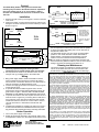
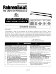
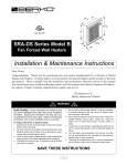
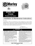
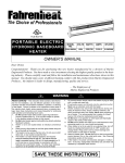
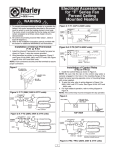
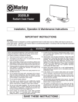
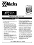
TOP VIEW
3-1/2
1 1/2"
(89mm)
21”
(532mm)
LEFT END
VIEW
FRONT VIEW
5”
(127mm)
5"
Surface Mounted
Utility Heater
HT500
5"
(127mm)
2 1/2"
(63mm)
21"
(532mm)
1"
(25mm)
3 1/2"
(89mm)
FILE #21609
Installation & Maintenance Instructions
Dear Owner,
Congratulations! Thank you for purchasing this new heater manufactured by a division of Marley
Engineered Products. You have made a wise investment selecting the highest quality product in the heating industry. Please carefully read the installation and maintenance instructions shown in this manual.
You should enjoy years of efficient heating comfort with this product from Marley Engineered Products...
the industry’s leader in design, manufacturing, quality and service.
... The Employees of
Marley Engineered Products
!
WARNING
Read Carefully - This instruction sheet contains vital information for
the proper installation, use and efficient operation of the heater.
Carefully read the manual before installation, operation or cleaning
of the heater. Failure to adhere to the instruction could result in fire,
electric shock, death, serious personal injury or property damage.
Save these instructions and review frequently for continuing safe
operation and instructing future users.
WARNING: HAZARD OF FIRE OR ELECTRICAL SHOCK
1. To prevent a possible electric shock, disconnect all power to
heater at main service panel before wiring or servicing.
2. All wiring must be in accordance with the National and Local
Electrical Codes and the heater must be grounded.
3. Do not install closer than 18” (456mm) to the floor or 12”
(304mm) from the ceiling. End of heater may be next to adjacent
walls. Do not install in vertical position.
4. Heater is hot when in use. Do not install the heater behind door,
behind towel rack, in closet, where curtains or drapes can touch
heater or where air flow through the heater may be obstructed.
Keep electrical cords, bedding, furniture and other combustible
away from heater.
5. Do not operate heater without cover in place. Cover must be
secured with screws to prevent unintentional removal.
6. Do not insert or allow foreign objects to enter or touch the heater
or heating element as this may cause an electric shock, fire or
damage to heater.
7. Heater has hot and arcing or sparking parts inside. Do not use
in areas where gasoline, paint, or flammable liquids are used or
stored.
8. Do not use this heater in an environment where heater will be
subjected to direct contact with water.
9. Do not use in a corrosive environment.
10. Supply voltage must be the same as heater voltage. Check
heater nameplate and supply voltage before energizing.
SAVE THESE INSTRUCTIONS
1
General
Do not use white wire in 240 volt circuit
N
White
The HT500 Utility Heater is designed for horizontal wall
mounting only. The built-in thermostat allows for adjustment
of the heat output from 40˚ to 70˚ F. The heater is factory
wired for use at 240/208 volts but can be re-wired for use at
120 volts.
Element
T’Stat
L1
To
240/ Black
208 V
Supply
Installation
Blue
L2
Blue
1. Remove the grille cover by removing the 2 screws on the front
of the cover.
2. Position the heater on wall at desired mounting location maintaining the minimum clearances as noted in Warning 3 and as
shown in Figure 1.
Blue
Blue
HT500 - Factory wired for 240/208 volt operation
500 watts, 2.1 amps @ 240 V
375 watts, 1.8 amps @ 208 V
Figure 2
To rewire for 120 volt
operation:
N
Ceiling
Heater
White
12”min.
(304mm)
To
120 V
Supply
L1
Black
Side
view
End
View
Figure 3
Floor
16”
(405mm)
.203”diameter holes
(5mm)
T-Stat
Blue
Blue
Blue
18”min.
(456mm)
21”
(532mm)
Element
1.75 ”
(44
mm)
(51 2”
mm)
5”
(127
mm)
Figure 1
1. Connect Blue “L2”
wire connection to
other element Blue
lead and thermostat
Blue lead. Remove
“L2” wire marker.
2. Connect 120 volts to
Black “L1” & White
“N”.
HT500 - Field re-wired for 120 volt operation
500 watts, 4.2 amps
in a few moments the heating element will become warm. If
the air temperature is above 70˚F, the heater will not operate.
A check of the thermostat setting has to occur when the air
temperature is below 70˚F
3. The thermostat range is from 40˚F at full counterclockwise
position to 70˚F at full clockwise. Position thermostat at
desired location. Thermostat will automatically cycle the
heater on and off to maintain the desired temperature.
NOTE: The heater is designed to provide freeze protection and
the thermostat may allow the heater to come on at the lowest
setting if the space temperature drops below 40˚ F.
Cleaning and Maintenance
NOTE: The heater MUST be mounted horizontally to allow air
flow freely upward through the heating element.
Thermostat can be located towards either end of heater.
3. Securely fasten the heater to the wall with screws or bolts
using the four (4) pre-drilled holes in the heater back.
This heater requires no maintenance. Periodic cleaning to
remove accumulated dust and dirt is recommended. This
should be done using a vacuum with brush. See Warning 1.
LIMITED WARRANTY
All products manufactured by Marley Engineered Products are warranted
against defects in workmanship and materials for one year from date of installation, except heating elements which are warranted against defects in workmanship and materials for five years from date of installation. This warranty
does not apply to damage from accident, misuse, or alteration; nor where the
connected voltage is more than 5% above the nameplate voltage; nor to
equipment improperly installed or wired or maintained in violation of the product’s installation instructions. All claims for warranty work must be accompanied by proof of the date of installation.
Wiring
1. Bring power supply cable to heater and install into heater
wiring compartment through the pre-punched 7/8” (22mm)
hole in the end of control box. Be sure to use cable clamp on
cable as required by the National Electric Code.
2. Connect the supply ground wire to the heater using the green
colored ground screw.
3. To operate the heater at 208 through 240 volts, connect
power supply wiring to heater wiring following the wiring diagram shown in Figure 2. DO NOT USE THE WHITE WIRE
MARKED “N” FOR WIRING TO 208 THROUGH 240 VOLTS.
4. To operate the heater at 120 volts requires the heater to be rewired as shown in Figure 3 by connecting blue L2 lead wire to
wire connection of the other element blue lead wire and thermostat blue lead wire. Remove the L2 wire marker. Connect
120 volts to the black L1 lead and the white N lead. See
Figure 3.
5. Complete the installation by replacing the grille cover using 2
screws removed earlier and 4 additional screws from parts
bag. Remove thermostat knob from the parts bag and install.
The customer shall be responsible for all costs incurred in the removal or reinstallation of products, including labor costs, and shipping costs incurred to
return products to Marley Engineered Products Service Center. Within the limitations of this warranty, inoperative units should be returned to the nearest
Marley authorized service center or the Marley Engineered Products Center,
and we will repair or replace, at our option, at no charge to you with return
freight paid by Marley. It is agreed that such repair or replacement is the exclusive remedy available from Marley Engineered Products.
THE ABOVE WARRANTIES ARE IN LIEU OF ALL OTHER WARRANTIES
EXPRESSED OR IMPLIED. AND ALL IMPLIED WARRANTIES OF MERCHANTABILITY AND FITNESS FOR A PARTICULAR PURPOSE WHICH
EXCEED THE AFORESAID EXPRESSED WARRANTIES ARE HEREBY
DISCLAIMED AND EXCLUDED FROM THIS AGREEMENT. MARLEY
ENGINEERED PRODUCTS SHALL NOT BE LIABLE FOR CONSEQUENTIAL DAMAGES ARISING WITH RESPECT TO THE PRODUCT, WHETHER
BASED UPON NEGLIGENCE, TORT, STRICT LIABILITY, OR CONTRACT.
Some states do allow the exclusion or limitation of incidental or consequential
damages, so the above exclusion or limitation may not apply to you. This warranty gives you specific legal rights, and you may also have other rights which
vary from state to state.
Heater Operation
For the address of your nearest authorized service center, contact Marley
Engineered Products in Bennettsville, SC, at 1-800-642-4328. Merchandise
returned to the factory must be accompanied by a return authorization and
service identification tag, both available from Marley Engineered Products.
When requesting return authorization, include all catalog numbers shown on
the products.
1. Turn on the power supply to the heater.
2. Rotate the thermostat clockwise to the warmest setting. If the
air temperature is below 70˚F the heater should come on and
SPX Corporation
470 Beauty Spot Rd. East
Bennettsville, SC 29512 USA
2
9/96
SWO 308 Part No. 5200-2314-000