1
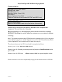
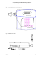
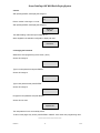
DataPage MK2
Desktop UHF Radio Paging System
Installation & User Manual
Scope Communications UK Ltd, Quantum House, Steamer Quay, Totnes, Devon TQ9 5AL
Tel: +44 1803 860700 Fax: +44 1803 863716 Email: [email protected] Web: www.scope-uk.com
DPMK2/6
Scope DataPage UHF MK2 Radio Paging System
PREFACE
Important Installation Information
It is the purchasers’ responsibility to determine the suitability of this equipment and its derivatives for any
given application, Scope cannot give specific advice in this manual, as each use will require independent
evaluation.
Scope has, wherever possible, employed extra safeguards to monitor the system’s performance. Certain
system installations, operational requirements or budgets may, however, limit the effectiveness of these
safeguards. Again, the suitability of the system for any given application must therefore be decided by the
installer and their customer, relative to the application and risk.
Good working practice dictates that a suitable system installation log must be generated, together with a
record of the dates when the system has been manually checked, (with the aid of signal strength meters
etc.) enabling the system performance to be compared with the original installation data.
For UK equipment, Scope has no control of the use and application of the frequencies issued by OFCOM.
Some equipment that is licensed may have greater protection than other equipment which is operated on a
WT Act License Exempt basis.
The supply of this equipment is governed by our standard terms and conditions of sale, which can be found
on the reverse of all order acknowledgements*, proforma invoices*, delivery notes, price lists and invoices.
Alternatively, these can be provided on request.
* Faxed proforma invoices and quotations refer to “conditions available upon request”.
Important Safety Information
Scope products are designed to operate safely when installed and used according to general safety
practices. The following requirements should be observed at all times.
Do NOT subject this equipment to:
Mechanical shock
Excessive humidity or moisture
Extremes of temperature
Corrosive liquids
This equipment is designed for indoor use, unless expressly stated otherwise, and must not be used in
classified Hazardous Areas, including areas containing explosive or flammable vapours, unless express
authorisation has been given in writing by the manufacturer. If in doubt, consult your local product dealer for
further information.
Do not obstruct any slots or openings in the product. These are provided for ventilation to ensure reliable
operation of the product and to protect it from overheating.
Only use a damp cloth for cleaning (not liquid or aerosol based cleaners), and ensure that any power is
removed from the unit prior to beginning the cleaning operation.
Removal of covers from the equipment must only be undertaken by authorised service personnel, who must
ensure that power is isolated prior to removal.
DPMK2/6
1
07/05
Scope DataPage UHF MK2 Radio Paging System
Preface
Installation
Installation must only be undertaken by an Approved contractor, who shall ensure that all work is carried out
in compliance with National Wiring Regulations. For mains powered equipment, a readily accessible
isolating fuse or switched socket must be located within 1 metre of the equipment.
No User Serviceable Parts
Alteration or modification to any part of this equipment, without the prior written consent of the manufacturer,
will invalidate all Approvals and Warranties attaching to the equipment. Further liability for the operation of
the equipment, under the applicable law, will pass to the user, who will absolve the manufacturer of any
further responsibility for it’s correct operation and use.
Liability
Scope does not accept liability for any damage or injury, howsoever caused as the result of misuse of this
equipment. It is the responsibility of the user to ensure that the equipment is operated in the manner for
which it was intended and that it is the correct item of equipment for the required task.
Warranty
This product is warranted as free from defects of workmanship and materials for a period of one year from
the original purchase date. During this time, if there is a defect or malfunction of this product, Scope will,
with proof of purchase, repair or replace at it’s discretion any defective parts, free of charge. This does not
include where the adjustments, parts and repair are necessary due to circumstances beyond the control of
Scope, including but not limited to fire or other casualty, accident, neglect, abuse, abnormal use or battery
leakage damage.
WARNING ! No User Serviceable Parts
Celui-ci ne contient aucune piece pouvant etre reparee par l’utilisateur
Caution ! Risk of electric shock, do not open.
Attention ! Risque de choc electrique, ne pas ouvrir.
Alteration or modification to any part of this equipment, without the prior written consent of the manufacturer,
will invalidate all manufacturer approvals and warranties. No adjustments can be undertaken except by
qualified and licensed persons as authorised by Scope.
This product complies with the essential requirements of the R&TTE Directive 1999/5/EC
Copies of the Declaration of Conformity covering this product can be obtained from Scope at:
Quantum House, Steamer Quay, Totnes TQ9 5AL United Kingdom.
Do not discard. At end of life this equipment must be sent to an authorised waste treatment centre. Contact
Scope at the above address for further details.
© Scope Communications UK Ltd, 2003 All Rights Reserved
DPMK2/6
2
07/05
Scope DataPage UHF MK2 Radio Paging System
Contents of this box:
DataPage Mk 2 UHF Base Station
Plugtop Power Supply
Internal Antenna
Jack plug, locking, 3.5mm (2 off)
User Manual
Licence Application Form (RA5)
Telephone interconnect lead (models NDPDTMF and NDPLP only)
Supplied separately, to order:
Numeric Display Pagers
Optional External Aerial/Coaxial Cable (See Section: Other aerials)
Please note you are required to obtain an OFCOM Licence to operate this
equipment. See section under ‘Licensing’.
Before attempting to use this equipment, please read the instructions carefully.
WARNING ! Operating the system without an antenna can cause extensive damage.
Licensing
Note ! This system requires a valid OFCOM licence for operation in the UK. It is the user’s
responsibility to apply for an On-Site Paging licence on form Of21 Private Business Radio
Licence Application Form, available online at www.ofcom.org.uk.
The relevant clauses on the Of21 form should be completed as follows:
Section 2, item 9. Tick “Self-Select PBR licence”
Section 4, item 28. Generally, antennas provided by Scope are Omni-Directional, with a
gain of 0 dB.
Section 4, item 30. ERP level:
0.5W as standard, 2W if the optional amplifier is fitted.
Please note that it is the user’s responsibility to apply for the relevant licence to OFCOM.
DPMK2/6
3
07/05
Scope DataPage UHF MK2 Radio Paging System
Description:
Your DataPage Mark 2 is supplied in one of three configurations:
1) NDP, the basic model, provides keyboard entry of data for message transmission.
Additionally, two volt-free (dry) contacts are provided for sending pre-programmed
messages. These contacts can be programmed for normally open, normally closed or
change of state operation (see page 3, Dry Contacts).
2) NDPDTMF: as above, with the addition of an interface suitable for connection to an
internal telephone system that is driven by DTMF tones i.e all internal telephones on the
internal exchange must be capable of sending dual tone multi frequency signals (DTMF)
from their own keypads to the extension socket selected to operate the paging system.
The vast majority of PABX telephone exchanges operate in this way.
3) NDPLP: as above, but for connection to keyphones and hybrid systems that use four
wire telephones and their own proprietary digital signalling protocol. In most cases, these
systems will not be able to send DTMF tones from all internal telephones to the selected
internal two wire extension socket. The NDLP model is therefore configured for
connection to a spare external line port by way of the AB wire. The telephone exchange
must then be programmed such that this line port is not automatically selected when
requesting an external line, but the internal extensions can select this line port either by
way of a pre programmed feature button or dialling a discreet code. This line port system
will work with all exchanges which will accept that the line port is active from the correct
line voltage being present. This system will not work where the exchange requires the line
port to receive digital dial tones .
Refer to Section 2: “Telephone Interface” for more comprehensive information.
Some major points to remember when installing the equipment:♦ Never install aerials near to overhead power lines or adjacent to telephone or public
address or data communication lines.
♦ Avoid, wherever possible, running aerial feeder cables alongside other cables eg:
telephone and mains.
♦ Avoid mounting the transmitter in the immediate vicinity of telephones, exchanges or
computer equipment. A few feet can make the world of difference in avoiding
interference from the radio frequency generated by the transmitter.
DPMK2/6
4
07/05
Scope DataPage UHF MK2 Radio Paging System
System Operation
1) Connect the 90 degree aerial to the BNC connector (bayonet twist lock) located at the side of the
transmitter. Slide the plastic cover over the connector, engaging the two lugs into the corresponding
recesses in the side of the case. This will maintain the aerial in an upright position, which is important for
optimising the range of the transmitter. See Figure 1.
2) Connect the power supply to the power socket located at the far right hand rear corner of the base
station. See Figure 2. Ensure the two jack plugs are fitted (DC1 and DC2), even if they are not wired to a
switch, as removal will trigger the unit when it is first powered up (unless they have been programmed out see Program Parameters, section 2: Inputs)
Important note: Only use the power supply supplied with your system! The use of non-approved supplies
will invalidate all warranty and service.
3) Check that the pagers have their batteries inserted and that they are turned on (refer to the individual
pager instruction manuals supplied with the system).
4) Plug the power supply into a convenient wall socket and turn on the power. When the unit is first
powered up the system will display the following screen for a few seconds:
SCOPE MARKETING
DataPage V1.00
Followed by:
ENTER PAGER No:
>
The flashing cursor invites you to enter a pager number (this can be any number between 1 and 9,999) after
which you must press ENTER for the number to be accepted. Pressing the CANCEL key at this stage will
return the user to the pager number prompt to begin again. Pressing the SEND key in place of the ENTER
key will transmit a tone only message to the pager using the default beep type .
5) After pressing ENTER, the next screen appears to offer the selection of the beep types. Again, the
flashing cursor invites you to enter a selection.
At this point the operator may choose to select a beep type 1,2,3 or 4,
or press ENTER without making a selection. This will attach the default
beep type to the call. (It should be noted that not all pager types
currently carry the transmitter selectable beep type). In the event that
your pagers are so equipped, selecting 1,2,3 and 4 will correspond to
beep types A, B, C and D respectively. Pressing the SEND key at this
stage will send a tone only message together with the beep type selected.
6) After selecting the beep type, press ENTER. The screen will now prompt
for you to enter a message of up to 20 digits, including [, ] and spaces.
Note: the screen will scroll after entering 15 digits.
7) After selecting the message, press ENTER or SEND. The call will now
be transmitted to the pager. A confirmation message will briefly appear
on the screen.
BEEP TYPE (1-4):
>
ENTER MESSAGE:
>
Sending Message
Please Wait
Pressing the ‘CANCEL’ key at any stage of operation and any entry level will immediately revert the unit to
the ‘ENTER PAGER No:’ prompt.
Dry Contacts
There are two volt-free (dry) contacts available for use with either Normally Open, Normally Closed or
Change of State switches (see Program Parameters, section 2: Inputs). When either is triggered, the
programmed message(s) will be sent to the selected pager (or group of pagers). When used in the
Normally Open mode only, the message will repeat whilst in the active state (can be used as a safety
mode).
Connection is via 3.5mm locking jack plugs at the rear of the unit (see fig. 2).
DPMK2/6
5
07/05
Scope DataPage UHF MK2 Radio Paging System
Fig. 1 Connecting the antenna and locking cover
Fig. 2 Connection port detail
DPMK2/6
6
07/05
Scope DataPage UHF MK2 Radio Paging System
Group Calls
As previously stated, this system will accept pager identities from number 1 through 9,999. Most pagers will
accept a minimum of two identities, enabling the pager to respond to selected group calls as well as its own
unique identity. Advanced pagers offer multiple identities, again, enabling one to be reserved for its own
unique identity and then for the pager to belong to a selected number of groups of pagers which can be
called collectively by entering just one identity or number. Sometimes the requirement is to have a global
call and upon the entry of this specific number the system will call all pagers at one time. As group calls are
created from single pager identities, any number of groups can be constructed to suit individual customers
requirements. The default Global Group Call number is 9999.
Performance
The system will normally cover 95% of all range requirements with the use of just the internal antenna. The
helical quarter wave antenna supplied with the system can provide ranges of up to half a mile free space
and will normally cover industrial buildings of up to 100,000 square feet or more. This short helical wound
antenna can be replaced with a straight quarter wave which can provide ranges in excess of one mile in free
space and considerably enhance the units performance in industrial or commercial environments. Position
the unit on the opposite end of the desk to computers, telephones and intercoms etc. to minimise the
potential for cross interference.
Also, remember that the capability of your system will be affected by:Foil backed plaster board, metal mesh, wire reinforced glass, metal sheeting, large mirrors, suspended
ceilings, lift shafts etc. These can all reflect and thereby reduce the signalling capability of the transmitter. A
little forethought prior to installation, coupled with a few tests, can normally avoid most of these problems
Other Aerials
The range and performance of this equipment can be improved by the addition of more efficient aerials*.
These can be installed either inside or outside the building and are connected to the transmitter with 50 ohm
coaxial cable.
A glass mount is available to install on the inside of a suitable window which can boost range, especially if
its required in one direction from the building.
The centre fed half wave di-pole measuring approximately 300 mm from tip to tip, will provide excellent all
round local signalling. This can be mounted either inside or outside the building and is available in either a
light weight or heavy duty stainless steel design.
The 6 dB end fed Colinear is intended for external application and will, when elevated, boost overall range
with a slight loss to some local signals.
Pre-terminated coaxial feeders are available for 5, 10 or 15 metre requirements. High frequencies can
equate to high power losses. Always use the best quality cable. RG58 is only acceptable on cable runs of
up to 5 metres. We recommend RG213 or equivalent on greater lengths. If in doubt consult our technical
department. Coaxial cable intended for TV satellite or CCTV installations is normally 75 ohm and therefore
totally unsuitable and can cause severe transmitter damage.
*Subject to licence conditions.
DPMK2/6
7
07/05
Scope DataPage UHF MK2 Radio Paging System
Program Parameters
The standard models are factory pre-set and should not under any circumstances be adjusted by the
customer. The factory settings can be viewed for the purposes of verification when ordering additional
components etc.
The system parameters are protected from accidental change by password control. To enter the system
type:
( 72765 then press ENTER
This is the default password. To alter this to a password of your own choice, see 5: Changing the
Password
You can escape from this programme at any time by pressing CANCEL. Upon acceptance of the password
the screen will change to :
1: Setup 2: Inputs
3: Phone 4: Serial
1: Setup
Press key 1. The screen changes to:
BASE PAGER ID:
>0090000
(The number shown is just an example)
To change the base pager ID enter the new number and press ENTER. In the event that you make a
mistake press CANCEL and start again.
After pressing ENTER, the screen display will change to prompt for the default beep type:
DEFAULT BEEP:
>1
You may enter a number in the range 1-4 which will correspond to the pager beep codes A, B, C, D
respectively. Note, not all pagers are equipped to respond to transmitted beep codes. Press ENTER to
confirm or CANCEL to return to the start.
After pressing ENTER, the screen display will change to prompt for the transmission data speed:
TRANSMIT SPEED:
> 1200 bps
Press key 1 to select 512 baud, key 2 to select 1200 baud or key 3 to select 2400 baud. Press ENTER to
return to the programming menu.
2: Inputs
Press key 2. The screen changes to:
INPUT COUNT 0-2
>
Select the number of dry contacts required: either 0, (none), 1 (DC1) or 2 (DC1 and DC2).
After pressing ENTER, the screen will change to:
ACTIVATE STATE:
: Normally Open
DPMK2/6
8
07/05
Scope DataPage UHF MK2 Radio Paging System
Pressing key 1 will display Normally Open
Pressing key 2 will display Normally Closed
Pressing key 3 will display Change of State
After making your selection, press ENTER to store.
Display will change to:
TRIG. TIME 0-15:
>
This indicates the time that the contacts must remain in the active state to effect a trigger. A value of
between 0 and 15 can be entered, which represents blocks of 0.25 seconds (approximately). Therefore, a
value of 14 would equate to 3.5 seconds.
After making your selection, press ENTER to store; display will change to:
REPT. TIME 0-15:
>
For added safety, when in Normally Open Mode the message is repeated whilst the contact remains in the
closed state. This screen allows you to select the time gap between each repeat transmission. Each unit
represents a block of 10 seconds.
After making your selection, press ENTER to store; display will change to:
INPUT 1 PAGER
>
Type in the pager no. which you wish to activate when contact 1 is triggered.
After making your selection, press ENTER to store; display will change to:
INPUT 1 TONE:
>
Select a number between 1 - 4 (represents bleep types A,B,C,D) to set the bleep type.
After making your selection, press ENTER to store; display will change to:
INPUT 1 MESSAGE:
>
Type in the numeric message you wish to appear on the pager. Press ENTER to store. Screen will then run
through the same sequence for contact no. 2 (if selected). When complete, screen will revert to the main
programming menu.
DPMK2/6
9
07/05
Scope DataPage UHF MK2 Radio Paging System
3: Phone (refer also to Section 2: Telephone Interface)
This section is only applicable to models: NDPDTMF, NDPLP
The telephone interface can be programmed through the keyboard as follows:
Press key 3. The screen will change to display:RINGS TO ANSWER:
>1
Select a number in the range 1-9 and press ENTER. This will define the number of rings before the system
will pick up the line. Pressing CANCEL will abort the change and return you to the programming menu.
Note, this value refers to the NDPDTMF model only, as the NDPLP version does not ring, but merely picks
up the line.
After pressing ENTER, the display will change to:
INACT’V TIMEOUT:
> 10
(The number shown is just an example)
Enter a number in the range 2-99 secs. This will adjust the inactivity time (i.e. no button presses) after which
the line will be dropped.
After pressing ENTER, the display will change to:
ANS TONE DELAY:
>2
This number must fall within the range of 1-99 (each unit = 0.1 sec approx.). This will adjust the delay time
from the moment the line is picked up to the time that the sign on tones are generated.
4: Serial
This connection is reserved for advanced programming and for specialist applications.
It will not therefore be accessible to the user for systems supplied in the standard configuration.
Press key 4. This sets the serial data communication speed between the transcoder and host. The screen
will change to display:
BAUD RATE (1-8)
9600
Enter a number in the range 1-8. 1=300, 2=600, 3=1200, 4=2400, 5=4800, 6=9600, 7= 19200, 8=38400
baud.
After pressing ENTER, the display will change to:
PARITY (1-3):
NONE
Enter a key in the range 1-3. 1=None, 2=Odd, 3=Even.
After pressing ENTER, the display will change to:
Enter a number in the range 7-8 to set.
DPMK2/6
DATA BITS (7-8):
>8
10
07/05
Scope DataPage UHF MK2 Radio Paging System
4: Serial
After pressing ENTER, the display will change to:
STOP BITS (1-2):
>1
Enter a number in the range 1-2 to set.
After pressing ENTER, the display will change to:
Serial Port
Set OK.
The default setting of the serial port is 9600, N, 8, 1
When supplied in the standard configuration, display will read:
Serial Port
Not Active
5: Changing the Password
Whilst at the main programming menu screen, press (
Screen will change to:
ENTER PASSWORD:
?
Type in current password and press ENTER.
Screen will change to:
NEW PASSWORD:
?
Type in new password and press ENTER.
Screen will change to:
CONFIRM PASSW’D:
?
Re-type the new password and press ENTER.
Screen will now read:
Password
Updated OK
The new password is now successfully stored.
To return to the pager entry screen press ENTER or CANCEL when at the main programming menu.
***************************************
DPMK2/6
11
07/05
Scope DataPage UHF MK2 Radio Paging System
Section 2
Telephone Interface (models NDPDTMF and NDPLP only)
Overview
IMPORTANT! For indirect connection to an internal PABX only. This unit must not under any circumstances
be connected direct to the PSTN.
The Scope digital paging interface can be used to transmit text or numeric messages from any telephone
connected to your exchange, direct to the pocket of the individual being paged. There are two types of
interface available, these cover all types of keyphone, hybrid and PABX systems with DTMF capability.
These can be supplied in two basic configurations:
1) ----LP. This interface connects to an external line port, it is supplied with a 50 volt supply to provide the
required voltage to the line port. This unit will work with any telephone system that can send DTMF to the
assigned port, without receiving a dial tone.
2) ----DTMF. This interface is only intended for use with systems dedicated to two wire ports. Access is
gained by dialling the extension number, the ringing will alert the system which will pick up the line. Use of
this interface with keyphones or hybrids of any sort is not recommended and we cannot provide any support
for such applications! Avoid any equipment with four wire capability!
Both of these interfaces contain BS6301 isolation devices. There is total electrical isolation between the
paging logic and power supply, and the PABX side of the apparatus.
Installation:
For interface type LP, the A and B wire of the external line port are connected to a 2/3a line jack on
terminals 2 and 5.
For the DTMF- PABX interface, use the lead provided to plug into a standard 2 wire extension socket as for
any (SLT) internal telephone.
Operation:
When the system leaves the factory, it will have been programmed with a default configuration which sets
up the system as follows:Number of pagers:
Default bleep type:
Password:
System Identity:
RANGES SET AS ORDERED
A
72765
REFER TO ORDER DOCUMENTATION
The system parameters can be changed and re-programmed via the keyboard, if required (see previous
section: Program Parameters, 3: Phone).
Your system has been programmed to be fully functional before leaving the factory, there is no need to
change any settings if you are happy with the factory settings.
DPMK2/6
12
07/05
Scope DataPage UHF MK2 Radio Paging System
Section 2
Telephone Interface (models NDPDTMF and NDPLP only)
Numeric pagers
STEP 1:- CONNECT TO SYSTEM
DIAL PAGING SYSTEM EXTENSION NUMBER OR LINE PORT
WAIT FOR SIGN-ON TONES (THREE NOTES ESCALATING LOW TO HIGH)
STEP 2:- ENTER PAGER NUMBER (OR GROUP NO.) TO BE CALLED
TYPE (PAGER NUMBER)
TYPE Ä
WAIT FOR ACCEPTANCE TONE OR PROCEED
(SINGLE MID TONE)
STEP 3: ENTER NUMERIC MESSAGE TO BE SENT COMPRISING 0,1,2,3,4,5,6,7,8,9.
TYPE (NUMERIC DIGITS MAX 20)
TYPE Ä
WAIT FOR SIGN OFF TONES
REPLACE HANDSET
(FOUR TONES HIGH,LOW,HIGH,LOW)
REJECTED DATA IS SIGNALLED BY A SINGLE LOW BEEP, RE-ENTER DATA FROM STEP 2 OR
REPLACE HANDSET, WAIT FOR TIME OUT AND START AGAIN.
Advanced features
When proficient at using the system, you can speed up your paging by not waiting for the prompt tones,
simply enter the pager number Ä message Ä and listen for the sign off tones. If you replace the
handset prior to hearing the sign off tones the page will be aborted. It is possible to send the page without
waiting for the sign on tones, this may well require the delay before sending the sign on tones to be
lengthened (see programming section on 'SET TIME BEFORE SIGN-ON TONES' ). To achieve this facility
you must send valid DTMF tones to be received by the system before the sign-on tones are generated. It is
therefore possible to extend the sign-on delay past the inactivity timer, which effectively means that the signon tones will never be received.
Speed dialling
It may be possible to effect some speed dial functions with your telephone system, however telephone
exchanges vary as to the way in which they perform depending upon their own internal protocol. With
certain systems you may have to establish an audio connection with the port prior to sending the message.
With other systems it may be possible to programme pauses between accessing the port, sending the pager
number and sending the message. If this is possible, it will be necessary to extend the 'TIME BEFORE
SIGN-ON TONES' to allow valid data to be sent before receiving the sign-on tones.
Tone only paging
Numeric and alphanumeric pagers can receive tone only calls by entering
Ä
in place of the message.
© Scope Communications UK Ltd, 2003 All Rights Reserved
DPMK2/6
13
07/05