1
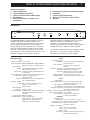
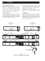
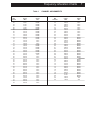
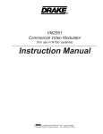
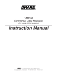
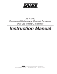
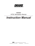
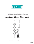
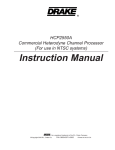
TM
300VMF+
Commercial Video Modulator
(For use in NTSC systems)
Instruction Manual
TM
is a trademark of the R.L. Drake Company
© Copyright 2005 R.L. Drake Company
P/N: 3853616D-10-2005
2
Caution Statements
IMPORTANT SAFEGUARDS
This symbol is intended to alert the user to the presence of
non-insulated "dangerous voltage" within the product's enclosure,
that may be of sufficient magnitude to constitute a risk of electric
shock to persons.
This symbol is intended to alert the user to the presence of
important operating and maintenance (servicing) instructions in the
literature accompanying the appliance.
CAUTION
TO REDUCE THE RISK OF FIRE OR
ELECTRIC SHOCK, DO NOT EXPOSE THIS
APPLIANCE TO RAIN OR MOISTURE
CAUTION
TO REDUCE THE RISK OF ELECTRIC SHOCK,
DO NOT REMOVE COVER (OR BACK)
NO USER SERVICEABLE PARTS INSIDE.
REFER SERVICING
TO QUALIFIED PERSONNEL.
WARNING: TO REDUCE THE RISK OF FIRE OR ELECTRIC SHOCK,
DO NOT EXPOSE THIS APPARATUS TO RAIN OR MOISTURE.
"CAUTION" -
Do not attempt to service this product yourself as opening or
removing covers may expose you to dangerous voltage or
other hazards. Refer all servicing to qualified service
personnel.
ATTENTION: POUR PREVENIR LES CHOCS ELECTRIQUES, NE PAS UTILISER CETTE
FICHE POLARISEE AVEC UN PROLONGATEUR, UNE PRISE DE
COURANT OU UNE AUTRE SORTIE DE COURANT, SAUF SI LES LAMES
PEUVENT ETRE INSEREES A FOND SANS EN LAISSER AUCUNE PARTIE
A DECOUVERT.
Important Safety Instructions
1.
2.
3.
4.
5.
6.
7.
8.
9.
9 a.
10.
11.
12.
13.
14.
Read these instructions.
Keep these instructions.
Heed all warnings.
Follow all instructions.
Do not use this apparatus near water.
Clean only with a dry cloth.
Do not block any ventilation openings. Install in accordance with the manufacturer's instructions.
Do not install near any heat sources such as radiators, heat registers, stoves, or other apparatus (including amplifiers)
that produce heat.
Do not defeat the safety purpose of the polarized or grounding-type plug. A polarized plug has two blades with one
wider than the other. A grounding type plug has two blades and a third grounding prong. The wide blade or the
third prong are provided for your safety. If the provided plug does not fit into your outlet, consult an electrician for
replacement of the obsolete outlet.
Mise à la terre ou Polarisation—Cet appareil est équipé avec un cordon d'alimentation à trois fils. Il est a brancher
sur une prise ayant un connecteur a la terre. Assurez-vous que la connection a la terre ne manque pas.
Protect the power cord from being walked on or pinched particularly at plugs, convenience receptacles, and the point
where they exit from the apparatus.
Only use attachments/accessories specified by the manufacturer.
Use only with the cart, stand, tripod, bracket, or table specified by the manufacturer, or sold with the apparatus. When
a cart is used, use caution when moving the cart/apparatus combination to avoid injury from tip-over.
Unplug the apparatus during lightning storms or when unused for long periods of time.
Refer all servicing to qualified service personnel. Servicing is required when the apparatus has been damaged in any
way, such as power-supply cord or plug is damaged, liquid has been spilled or objects have fallen into the
apparatus, the apparatus has been exposed to rain or moisture, does not operate normally, or has been dropped.
Table of Contents/Description/Specifications
3
TABLE OF CONTENTS
2
2
3
3
4
Caution Statements
Important Safety Instructions
Table of Contents / General Description
Specifications
Front Panel Controls, Indicators, and
Connections
5
6
7
8
9
Rear Panel Connections and Internal Jumper
Installation
Frequency Allocation Charts
Service / If You Need To Call For Help
Warranty
DESCRIPTION
The DRACOM 300VMF+ Video Modulator is a vestigial
sideband heterodyne audio/video modulator that
provides a modulated visual and aural RF carrier output
on any single EIA standard channel from channel 2
through channel 78 plus channels 95 to 99. This range
covers 54 through 552 MHz. Consult factory for custom
channels. All aeronautical channels are offset positive
with a tolerance of ±5 kHz as required by FCC rules. The
300VMF+ is designed to accept video and audio
SPECIFICATIONS
RF
Frequency Range: 54 - 552 MHz.
Channels Available: Factory ordered for a single channel:
EIA CATV channels 2 to 78 and 95 to 99.
FCC Frequency
Offsets: All aeronautical channels offset positive
with a tolerance of ±5 kHz.
Output Level: +55 dBmV, (typically adjustable from +43
to +55 dBmV).
Output Impedance: 75 OHMS, return loss of 14 dB, nominal.
Output Test: -30 dB, ±3 dB (referenced to
RF OUTPUT level).
A/V Ratio: Audio Carrier -20 to -12 dB referenced to
video carrier, adjustable.
Frequency Stability,
Visual: Within ±10 kHz of assigned channel
frequency; ±5 kHz on FCC
offset channels.
Aural Intercarrier
Frequency: 4.5 MHz, ±5 kHz.
Spurious Outputs: -60 dBc minimum, measured at -15 dB A/V
ratio and with modulator output level of
+55 dBmV.
In-Channel C/N: Better than 60 dB.
Broadband Noise: -95 dBc @ ±30 MHz or
greater spacings. (Specified levels are
referenced to the video carrier and
measured in a 4 MHz bandwidth).
baseband signals from a satellite receiver, TV camera,
video tape recorder, TV demodulator or similar
equipment. The heterodyne conversion system, in
conjunction with the use of a SAW filter, insures optimum
vestigial selectivity for adjacent channel headends.
The modulator accepts standard (sync negative) polarity
video at a 0.7 -1.5 Vpp level. All level controls are
located on the front panel for ease of operation.
VIDEO
Input level for 87.5%
Modulation: 1 Vp-p ±3 dB, manual gain adjust with
front panel control.
Input Impedance: 75 Ohms, return loss of 18 dB
minimum.
Frequency Response: Flat ±2 dB from 30 Hz to 4.2 MHz.
Video S/N: 60 dB, luminance weighted.
L/C Delay: Within 50 nSec of 0 nSec L/C delay
(complies with FCC rules, 76.605).
Differential Gain: Less than ±5% (10 to 90% APL).
Differential Phase: Less than ±5 degrees (10 to 90% APL).
AUDIO
Input Level for
25 kHz Peak Deviation: 175 mV rms minimum. Manual gain
adjustment with front panel control.
Input Impedance: 10K Ohms, unbalanced.
Pre-emphasis: 75 µSec.(flat by moving internal jumper)
Frequency Response: 40 Hz to 15 kHz, ±1.5 dB, referenced to
75 µSec pre-emphasis curve.
4.5 MHz Intercarrier Stability: Within ±5 kHz, 00 C to +500 C.
Total Harmonic Distortion: 1.5% maximum.
Hum and Noise: -60 dB minimum, referenced
to 25 kHz peak deviation.
GENERAL
Modulator Power
Requirement: 115 VAC ±10%, 60Hz, 10 Watts.
Auxiliary AC Outlet: Nominal 120 VAC, 600 Watts, maximum.
Total AC Power Input: Nominal 120 VAC 60 Hz,
610 Watts, maximum.
Operating Temperature
Range: 00 C to +500 C, ambient.
Size: 19" W x 1.75" H x 4.0" D.
Weight: 3.6 lbs.
Connectors: Video input, Audio input, RF output, and
Monitor output are all type F.
4
Front Panel Description
F1
F2
F3
F4
F5
F6
F7
Figure 1
F1 - POWER Indicator
Lights when the unit is connected to a source of AC
power.
F2 - OUTPUT TEST Connector
Provides a reduced level sample of the RF output signal.
The level at this connector is approximately 30 dB lower in
level than the RF OUTPUT signal. It is used to monitor
the active signal without affecting the level or quality of the
RF output signal.
F3 - CHANNEL Designation
The label indicates the fixed channel output for your
particular model. The 300VMF+ is capable of fixed
channel output (factory tuned) within the following
ranges: Channel 2 through 78 and 95 through 99.
F4 - RF OUTPUT LEVEL
This screwdriver adjustment permits decreasing the RF
output level a minimum of 12 dB below its specified
output level as the control is rotated counterclockwise.
The maximum output level of +55 dBmV is set with the
adjustment approximately fully clockwise.
NOTE: If an output level of less than +43 dBmV is
required, add an attenuator of the appropriate value at
the modulator output.
Example: For an output level of +35 dBmV, add a 12 dB
attenuator pad to the modulator output and set the
output level to +47 dBmV.
F5 - A/V RATIO Control
This screwdriver adjustment varies the level of the aural
carrier over a range from 12 to 20 dB below the visual
carrier. The aural carrier should normally be adjusted to
approximately 15 dB below the visual carrier (normal
operation). Clockwise rotation increases the aural carrier
level and thus decreases the A/V ratio.
F6 - AUDIO LEVEL Control
The setting of this screwdriver adjustment determines the
peak aural carrier deviation. Clockwise rotation
increases the carrier deviation. After installing the unit,
and with an audio source connected, adjust the AUDIO
LEVEL control for 25 kHz deviation. If an audio
modulation meter is not available, use a TV set and
adjust for equal volume as compared to a known off-air
broadcast. Monitor for a few minutes to assure that
maximum volume of the audio source program does not
cause an over-modulation condition.
F7 - VIDEO LEVEL Control
The setting of this screwdriver adjustment determines the
video modulation level. Clockwise rotation increases the
modulation depth. After installing the unit, and with a
nominal 1 Volt P-P video source connected, adjust the
VIDEO LEVEL control for the correct percentage of
modulation (87.5%). If test equipment is not available for
such measurements, then adjust for proper picture
contrast when viewed on a TV set (compare with known
off-air broadcast picture quality).
Rear Panel Description and Internal Jumper
VIDEO
INPUT
AUDIO
INPUT
120V AC
60Hz 610W
R.F.
OUTPUT
R. L. DRAKE COMPANY
FRANKLIN, OH
600W MAX
R1
R2
R3
5
R4
MADE IN TAIWAN
R5
Figure 2
R1 - VIDEO INPUT Connector
This is the baseband video input to the IF circuits. This
input accepts baseband through 4.2 MHz video at levels
from 0.7 Vp-p to 1.5 Vp-p.
R4 - AC OUTLET Receptacle
This is a power receptacle for other equipment and is
rated at 600 W maximum; 120 V, 5 Amp. This receptacle
is unfused and unswitched.
R2 - AUDIO INPUT Connector
This is an unbalanced audio input to the IF circuits. This
input accepts 40 Hz through 15 kHz audio at a nominal
level of 250 mV RMS (approximately -10 dBu).
If a separate BTSC stereo encoder, such as the Drake
MMTS20, is to be used with this modulator, this jack can
input 40 Hz through over 50 kHz with flat response if
internal jumper J8 is set to flat - see below)
R5 - LINE CORD
This is a three-wire power cable. When the cable is
connected to a properly wired AC power line outlet, this
cable grounds the instrument cabinet. Connect to a
115 VAC ±10%, 60 Hz source. Do not defeat the safety
purpose of the attached line cord plug.
R3 - RF OUTPUT
This is the modulator output.
INTERNAL JUMPER SETTING - AUDIO RESPONSE
Internal jumper J8 may be used to disable the 75 uSec
pre-emphasis (normal setting). Flat response may be
chosen if an external BTSC stereo signal is to be input to
the modulator through the audio input jack. To access this
jumper, disconnect the unit from AC power. Remove the
three screws holding the top cover of the chassis in place.
Remove top cover. J8 is a three pin header with J8
printed on the PCB. After setting this jumper, reinstall the
cover before returning power to the unit.
NORMAL RESPONSE of 75 uSec = Jumper in the 1-2
position (shorting pins 1 and 2 of the J8 header). Use this
setting for normal mono audio input. This is the factory
default setting.
FLAT RESPONSE = Jumper in the 2-3 position (shorting
pins 2 and 3 of header J8). Change to this setting when
an external BTSC stereo encoder is used with the
300VMF+.
6
Installation
CONNECTIONS AND CONTROLS
All connections to and from the 300VMF+ are made through
the rear panel. Figure 4 shows a typical two channel
installation using a typical satellite receiver as a signal
source. Additional channels can be added by using
additional 300VMF+ modulators and either multi-port
combiners or combinations of two-port combiners.
The 'RF Output Level' and 'A/V Ratio' controls are used
respectively to make these adjustments. If an output level of
less than +43 dBmV is required, add an attenuator of the
appropriate value to the modulator output.
Example: For an output level of +35 dBmV, add a 12 dB
attenuator pad to the modulator output and set the output
level.
INSTALLATION NOTES
Level adjustment provides optimum performance in
multichannel installations. The modulator outputs should be
checked periodically with a spectrum analyzer to maintain a
±1 dB variation of adjacent channel carriers. Aural/Visual
(A/V) ratios should be held to -15 dB or less.
RACK MOUNTING
Adequate ventilation is very important in multichannel
installations. Units should be spaced apart by at least one
panel height wherever possible, and some air movement is
advisable in enclosed rack cabinets. Excessive heat will
shorten component life and modulator performance will be
degraded without proper cooling.
TYPICAL
SATELLITE RECEIVER
REAR PANEL
VIDEO
OUT
H
V
TYPICAL
SATELLITE RECEIVER
REAR PANEL
VIDEO
OUT
AUDIO
OUT
H
V
AUDIO
OUT
AUDIO
VIDEO
300VMF+
AUDIO
INPUT
R. L. DRAKE COMPANY
FRANKLIN, OH
120V AC
60Hz 610W
R.F.
OUTPUT
MADE IN TAIWAN
600W MAX
AUDIO
300VMF+
R. L. DRAKE COMPANY
FRANKLIN, OH
120V AC
60Hz 610W
R.F.
OUTPUT
MADE IN TAIWAN
600W MAX
OUT
IN
2-WAY SPLITTER/
COMBINER
3611
2-WAY SPLITTER
AUDIO
INPUT
5-1000 MHz -130 dB RFI
VIDEO
INPUT
VIDEO
RF OUT
Figure 4
TYPICAL MULTIPLE MODULATOR INSTALLATION
OUT
VIDEO
INPUT
Frequency Allocation Charts
Table 1
7
CHANNEL ASSIGNMENTS
EIA
Channel
Visual
Carrier
MHz
Offset
kHz
EIA
Channel
Visual
Carrier
MHz
Offset
kHz
02
03
04
05
06
07
08
09
10
11
12
13
14
15
16
17
18
19
20
21
22
23
24
25
26
27
28
29
30
31
32
33
34
35
36
37
38
39
40
41
42
43
55.25
61.25
67.25
77.25
83.25
175.25
181.25
187.25
193.25
199.25
205.25
211.25
121.25
127.25
133.25
139.25
145.25
151.25
157.25
163.25
169.25
217.25
223.25
229.25
235.25
241.25
247.25
253.25
259.25
265.25
271.25
277.25
283.25
289.25
295.25
301.25
307.25
313.25
319.25
325.25
331.25
337.25
NONE
NONE
NONE
NONE
NONE
NONE
NONE
NONE
NONE
NONE
NONE
NONE
±12.5
±12.5
±12.5
NONE
NONE
NONE
NONE
NONE
NONE
NONE
±12.5
±12.5
±12.5
±12.5
±12.5
±12.5
±12.5
±12.5
±12.5
±12.5
±12.5
±12.5
±12.5
±12.5
±12.5
±12.5
±12.5
±12.5
±25
±12.5
44
45
46
47
48
49
50
51
52
53
54
55
56
57
58
59
60
61
62
63
64
65
66
67
68
69
70
71
72
73
74
75
76
77
78
95
96
97
98
99
343.25
349.25
355.25
361.25
367.25
373.25
379.25
385.25
391.25
397.25
403.25
409.25
415.25
421.25
427.25
433.25
439.25
445.25
451.25
457.25
463.25
469.25
475.25
481.25
487.25
493.25
499.25
505.25
511.25
517.25
523.25
529.25
535.25
541.25
547.25
91.25
97.25
103.25
109.25
115.25
±12.5
±12.5
±12.5
±12.5
±12.5
±12.5
±12.5
±12.5
±12.5
±12.5
NONE
NONE
NONE
NONE
NONE
NONE
NONE
NONE
NONE
NONE
NONE
NONE
NONE
NONE
NONE
NONE
NONE
NONE
NONE
NONE
NONE
NONE
NONE
NONE
NONE
NONE
NONE
NONE
±25
±25
8
Service / If You Need To Call For Help
SERVICE INFORMATION
You may contact the R.L. DRAKE Service Department for
additional information or assistance by calling
+1 (937) 746-6990, Monday through Friday, between
8:00 A.M. and 4:00 P.M. Eastern Time, except on holidays.
You may also contact the R.L. DRAKE Service Department by
E-mail at the following address:
[email protected]
or by Telefax:
+1 (937) 806-1576.
IF YOU NEED TO CALL FOR HELP
Call our Customer Service/Technical Support line at
+1 (937) 746-6990 between 8:00 A.M. and 4:00 P.M.
Eastern Time, weekdays. Please have the unit’s serial
number available. We will also need to know the specifics
of any other equipment connected to the unit.
When calling, please have the unit up and running, near
the phone if possible. Our technician(s) will likely ask
certain questions to aid in diagnosis of the problem. Also,
have a voltmeter handy, if possible.
R.L. DRAKE also provides technical assistance by
e-mail: [email protected]
or by Telefax: +1 (937) 806-1576.
Many of the products that are sent to us for repair are in
perfect working order when we receive them. For these
units, there is a standard checkout fee that you will be
charged. Please perform whatever steps are applicable
from the installation sections of the Owner's Manual
before calling or writing—this could save unnecessary
phone charges. Please do not return the unit without
contacting R.L. DRAKE first: it is preferred to help
troubleshoot the problem over the phone (or by mail) first,
saving you both time and money.
Inside the carton, enclose a note with your name,
address, daytime phone number, and a description of the
unit’s problem.
The unit must be sent to the following address:
Service Department
R.L. DRAKE COMPANY
230 Industrial Drive
Franklin, Ohio 45005 U.S.A.
Be sure to include your street address which will be
needed for UPS return. UPS Surface (Brown Label) takes
7-10 days to reach us depending on your location, Blue
takes 2-3 days.
Should you want to return your unit for service, package
the unit carefully using the original carton or other
suitable container.
Write your return address clearly on the shipping carton
and on an enclosed cover letter describing the service
required, symptoms or problems. Also include your
daytime telephone number and a copy of your proof of
purchase.
The unit will be serviced under the terms of the
R.L. DRAKE COMPANY Limited Warranty and returned
to you.
Red is an overnight service. Send the unit in a way that it
can be traced if we can’t verify receipt of shipment. We
suggest UPS or insured postal shipment.
If the unit is still under the original owner’s warranty,
R.L. DRAKE will pay the cost of the return shipment to
you. Our return shipping policy is that we will return it
UPS Brown if received Brown or by US Mail, it will be
returned Blue if received Blue or Red—or it will be
returned however you prefer if you furnish the return cost
for the method you select.
If the unit is out of warranty, use one of the following
methods for return shipment:
1) You designate billing to American ExPress, VISA,
MasterCard or Discover card;
2) You prepay the service charges with a personal check,
or
3) You specify some other method of return and payment.
When calling, the technician can estimate the repair
charges for you over the phone. This is another good
reason to call before sending a unit in for repair.
Typically, equipment is repaired in five to ten working
days after it arrives at R.L. DRAKE if we have all the facts.
If we must call you, it may take longer. R.L. DRAKE is not
responsible for damage caused by lightning, nonprofessional alterations, “acts of God”, shipping damage, poor
storage/handling, etc. R.L. DRAKE will make note of any
shipping damage upon receipt.
You will need to send proof of purchase to receive
warranty service. Typically, a copy of the invoice from an
R.L. DRAKE dealer will suffice. The warranty is for the
original owner only and is not transferable.
Warranty
Warranty9
One Year Limited Warranty
R. L. DRAKE COMPANY warrants to the original purchaser this product shall be free from defects in material or
workmanship for one (1) year from the date of original purchase.
During the warranty period the R. L. DRAKE COMPANY or an authorized Drake service facility will provide, free of charge,
both parts and labor necessary to correct defects in material and workmanship. At its option, R. L. DRAKE COMPANY
may replace a defective unit.
To obtain such a warranty service, the original purchaser must:
(1) Retain invoice or original proof of purchase to establish the start of the warranty period.
(2) Notify the R. L. DRAKE COMPANY or the nearest authorized service facility, as soon as possible after discovery
of a possible defect, of:
(a) the model and serial number,
(b) the identity of the seller and the approximate date of purchase; and
(c) A detailed description of the problem, including details on the electrical connection to associated equipment and the
list of such equipment.
(3) Deliver the product to the R. L. DRAKE COMPANY or the nearest authorized service facility, or ship the same in its
original container or equivalent, fully insured and shipping charges prepaid.
Correct maintenance, repair, and use are important to obtain proper performance from this product. Therefore carefully
read the Instruction Manual. This warranty does not apply to any defect that R. L. DRAKE COMPANY determines is
due to:
(1) Improper maintenance or repair, including the installation of parts or accessories that do not conform to the quality
and specifications of the original parts.
(2) Misuse, abuse, neglect or improper installation.
(3) Accidental or intentional damage.
All implied warranties, if any, including warranties of merchantability and fitness for a particular purpose, terminate one
(1) year from the date of the original purchase.
The foregoing constitutes R. L. DRAKE COMPANY’S entire obligation with respect to this product, and the original
purchaser shall have no other remedy and no claim for incidental or consequential damages, losses or expenses. Some
states do not allow limitations on how long an implied warranty lasts or do not allow the exclusions or
limitation
of incidental or consequential damages, so the above limitation and exclusion may not apply to you.
This warranty gives you specific legal rights and you may also have other rights which vary from state to state.
This warranty shall be construed under the laws of Ohio.
For Service, contact:
R.L. DRAKE COMPANY
230 Industrial Drive
Franklin, Ohio 45005 U.S.A.
Customer Service and Parts Telephone: +1 (937) 746-6990
Telefax: +1 (937) 806-1576
World Wide Web Site: http://www.rldrake.com
R.L. Drake Company
230 Industrial Drive
Franklin, Ohio 45005 U.S.A.
Customer Service and Parts Telephone: +1 (937) 746-6990
Telefax: +1 (937) 806-1576
World Wide Web Site: http://www.rldrake.com