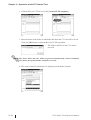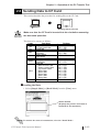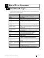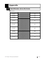
1
PC Transfer Tool Operation Manual Digital Electronics Corporation PREFACE Thank you for purchasing “PC Transfer Tool”. PC Transfer Tool allows you to perform maintenance operations easily, (uploading to or downloading from GP), even when the Screen creation software “GP-PRO/ PB III for Windows” is not installed to the PC on the production site. To ensure the safe and correct use of this product, be sure to read all related materials carefully and keep them nearby so that you can refer to them whenever required. NOTICE 1. The copyrights to all programs and manuals included in the PC Transfer Tool (hereinafter referred to as “this product”) are reserved by Digital Electronics Corporation. 2. The contents of this manual have been thoroughly inspected. However, if you should find any errors or omissions in this manual, contact your local sales representative. 3. Regardless of the above clause, Digital Electronics Corporation shall not be held responsible for any damages, third-party claims or losses resulting from the use of this product. 4. Differences may exist between the descriptions found in this manual and the actual functioning of this software. Therefore, the latest information on this software is provided in the form of data files (ReadMe.txt files, etc.) and/or separate documents. Refer to these sources as well as this manual prior to use. 5. Even though the information contained in and displayed by this product may be related to intangible or intellectual properties of Digital Electronics Corporation or third parties, Digital Electronics Corporation shall not warrant or grant the use of said properties to any users or other third parties. © 2004 Digital Electronics Corporation. All rights reserved. Digital Electronics Corporation September 2004 For information about the rights to trademarks and trade names, see “TRADEMARK RIGHTS.” PC Transfer Tool Operation Manual 1 Preface TABLE OF CONTENTS PREFACE .................................................................................................... 1 TRADEMARK RIGHTS ................................................................................ 3 OPERATING ENVIRONMENT ..................................................................... 4 MANUAL SYMBOLS AND TERMINOLOGY .............................................. 7 CHAPTER1 1.1 PC Transfer Tool ........................................................................................ 1–1 CHAPTER2 2.1 2.2 OVERVIEW OF THE PC TRANSFER TOOL OPERATION OF THE PC TRANSFER TOOL Start-up and Initial Setting of the PC Transfer Tool .............................. 2–1 2.1.1 Installing the PC Transfer Tool ....................................................... 2–1 2.1.2 Operational Procedure ................................................................... 2–2 2.1.3 Starting and Exiting the PC Transfer Tool ....................................... 2–3 2.1.4 Communication Settings ................................................................. 2–4 Receiving the GP Data (Backup) ............................................................. 2–6 2.2.1 Saving a Backup File (Reusable) .................................................... 2–6 2.2.2 Saving a Backup File (Non-reusable) ............................................ 2–8 2.3 Sending the Edited Screen Data to the GP (Restore) ........................... 2–9 2.4 Comparing the Data with the GP Data (Verify) ................................... 2–11 2.5 Receiving Data from the CF Card ......................................................... 2–13 2.6 Sending Data to CF Card ........................................................................ 2–15 CHAPTER3 3.1 Precautions on File Conversion ................................................................ 3–1 CHAPTER4 4.1 CONVERSION FROM A MEM FILE TO A PRW FILE LIST OF ERROR MESSAGES List of Error Messages ............................................................................. 4–1 APPENDIX A.1 2 Identification (Core ID) Code ................................................................. A–1 PC Transfer Tool Operation Manual Preface TRADEMARK RIGHTS The company names and product names used in this manual are the trade names, trademarks (including registered trademarks), and service marks of their respective companies. This product omits individual descriptions of each of these rights. Trademark / Tradename Right Holder Windows 98, Windows Me, Windows NT , Windows 2000, Microsoft, U.S. Windows XP, Windows Explorer Intel, Pentium Intel, U.S. Digital Electronics Corporation Pro-face (in Japan and other countries) Ethernet Western Digital, U.S. IBM compatible IBM, U.S. Adobe, Acrobat Adobe Systems Incorporated The following terms differ from the abovementioned trade names and trademarks. Term used in this manual Formal Tradename or Trademark Windows 98 Windows Me Windows NT Windows 2000 Windows XP Microsoft® Windows® 98 Operating System Microsoft® Windows® Me Operating System Microsoft® Windows NT ® Operating System Microsoft® Windows® 2000 Operating System Microsoft® Windows® XP Operating System PC Transfer Tool Operation Manual 3 Preface OPERATING ENVIRONMENT Compliant Operating Systems Item Description Compliant OS Windows 98, Windows Me, Windows NT, Windows 2000, Windows XP Software version C-Package03 SP1 and later Transfer cable (GPW-CB02) Connection method USB transfer cable (GPW-CB03) Ethernet connection List of Compatible Models GP Series Series Product Name GP-H70L GP-H70 series GP-H70S GP-270L GP-270 series GP-270S GP-370L GP-370 series GP-370S GP-470 series GP-470E GP70 series GP-570L GP-570S GP-570 series GP-570T GP-571 series GP-57JS GP-570VM GP-571T GP-675S GP-675 series GP-675T GP-870 series GP-37W2 series GP-870VM GP-37W2B GP-377L GP-377 series GP-377R series GP-377RT GP-477R series GP-477RE GP77R series GP-577RS GP-577R series 4 GP-377S GP-577RT Model GPH70-LG11-24V GPH70-LG41-24VP GPH70-SC11-24V GPH70-SC41-24VP GP270-LG11-24V GP270-LG21-24VP GP270-LG31-24V GP270-SC11-24V GP270-SC21-24VP GP270-SC31-24V GP370-LG11-24V GP370-LG21-24VP GP370-LG31-24V GP370-LG41-24VP GP370-SC11-24V GP370-SC21-24VP GP370-SC31-24V GP370-SC41-24VP GP470-EG11 GP470-EG21-24VP GP470-EG31-24V GP570-LG11-24V GP570-LG21-24V GP570-SC11 GP570-SC21-24VP GP570-SC31-24V GP570-TC11 GP570-TC21-24VP GP570-TC31-24V GP57J-SC11 GP570-TV11 GP571-TC11 GP675-SC11 GP675-TC11 GP675-TC41-24VP GP870-PV11 GP37W2-BG41-24V GP377-LG11-24V GP377-LG41-24V GP377-SC11-24V GP377-SC41-24V GP377R-TC11-24V GP377R-TC41-24V GP477R-EG11 GP477R-EG41-24VP GP577R-SC11 GP577R-SC41-24VP GP577R-TC11 GP577R-TC41-24VP GP Type GPH70L GPH70S GP270L GP270S GP370L GP-370S GP470 GP570L GP570 GP570VM GP571T GP675 GP870VM GP37W2 GP377L GP377S GP377R GP477R GP577R PC Transfer Tool Operation Manual Preface Series GP2000H series GP-2301H series GP-2401H series GP-2300 series GP-2301 series GP2000 series GP-2400 series GP-2401 series GP-2500 series GP-2501 series Product Name Model GP Type GP-2301HL GP2301H-LG41-24V GP2301HL GP-2301HS GP2301H-SC41-24V GP2301HS GP-2401HT GP2401H-TC41-24V GP2401H GP-2300L GP-2300S GP-2300T GP-2301L GP-2301S GP-2301T GP-2400T GP-2401T GP-2500L GP-2500S GP2300-LG41-24V GP2300-SC41-24V GP2300-TC41-24V GP2301-LG41-24V GP2301-SC41-24V GP2301-TC41-24V GP2400-TC41-24V GP2401-TC41-24V GP2500-LG41-24V GP2500-SC41-24V GP2500-TC11 GP2500-TC41-24V GP2501-LG41-24V GP2501-SC11 GP2501-TC11 GP2600-TC11 GP2600-TC41-24V GP2601-TC11 GP2300L GP2300S GP2300 GP2301L GP2301S GP2301 GP2400 GP2401 GP2500L GP2500S GP-2500T GP-2501L GP-2501S GP-2501T GP-2600 series GP-2600T GP-2601 series GP-2601T GP2500 GP2501L GP2501S GP2501 GP2600 GP2601 GLC Series Series GLC100 series GLC300 series Model GP Type GLC100L GLC100-LG41-24V GLC100S GLC100-SC41-24V GLC100S GLC300T GLC300-TC41-24V GLC300T GLC2300L GLC2300-LG41-24V GLC2300L GLC2300T GLC2300-TC41-24V GLC2300 GLC2400 series GLC2400T GLC2400-TC41-24V GLC2400*1 GLC2500 series GLC2500T GLC2600 series GLC2600T GLC100 series GLC300 series GLC2300 series GLC2000 series Product Name GLC2500-TC41-24V GLC2500-TC41-200V GLC2600-TC41-24V GLC2500-TC41-200V GLC100L GLC2500 GLC2600*1 Data backup operation cannot be performed from a GP to which the data has been transferred using the GP-PRO III or GP-PRO/PB III (MSDOS version). PC Transfer Tool Operation Manual 5 Preface LT Series Series LT Type A series Type LT Type A1 Model GLC150-BG41-XY32SK-24V GP Type LT TypeA LTC Type A1 GLC150-SC41-XY32SK-24V LTC TypeA LT Type A2 GLC150-BG41-XY32SC-24V LT TypeA LT Type B GLC150-BG41-FLEX-24V LT Type B/B+ series LT Type B+ LT Type C series GLC150-BG41-XY32KF-24V LTC Type B+ GLC150-SC41-XY32KF-24V LT Type C GLC150-BG41-RSFL-24V LT TypeB/B+ LTC TypeB+ LT TypeC GLC150-BG41-ADK-24V LT series LT Type H1 GLC150-BG41-ADPK-24V LT TypeH GLC150-BG41-ADTK-24V GLC150-SC41-ADK-24V LT Type H series LTC Type H1 GLC150-SC41-ADPK-24V LTC TypeH GLC150-SC41-ADTK-24V GLC150-BG41-ADC-24V LT Type H2 GLC150-BG41-ADPC-24V LT TypeH GLC150-BG41-ADTC-24V ST Series Series Product name Model GP Type ST400 ST400-AG41-24V ST400 ST401 ST401-AG41-24V ST401 ST402 ST402-AG41-24V ST402 ST403 ST403-AG41-24V ST403 ST series Factory Gateway Product name Factory Gateway 6 Model FGW-SE41-24V GP Type Factory Gateway FGW-SE PC Transfer Tool Operation Manual Preface MANUAL SYMBOLS AND TERMINOLOGY This manual uses the following symbols and terminology. If you have any questions about the contents of this manual, please contact your local Pro-face sales distributor. If you have any question about your personal computer or the Windows® software, please contact your local distributor or manufacturer. Safety Symbols and Terms This manual uses the following symbols and terms for important information related to the correct and safe operation of this product. Symbol Description Incorrect operation resulting from negligence of this instruction may cause death or serious injury. Incorrect operation resulting from negligence of this instruction may cause personal injury or damage to equipment. Failure to observe this instruction may cause abnormal operation of equipment or data loss. Instructions / procedures that must be performed to ensure correct product use. Actions / procedures that should NOT be performed. PC Transfer Tool Operation Manual 7 Preface Memo 8 PC Transfer Tool Operation Manual 1 Overview of the PC Transfer Tool 1.1 PC Transfer Tool As illustrated below, PC Transfer Tool is a software program that allows you to download data easily to GP or upload data from GP even when the GP Screen creation software “GP-PRO/PB III for Windows C-Package” is not installed to the PC. The files are downloaded or uploaded in backup file format (***.MEM) *1. This eliminates the risk of being edited in the process of transferring the files to the GP on the production site in maintenance operations. Make sure that the Transfer cable (GPW-CB02) and USB transfer cable (GPWCB03) are connected and that Ethernet connection is established when operating PC Transfer Tool. Notebook PC that is portable to the production site: With PC Transfer Tool installed Backup file (***.MEM)*2 Restore (Send) Backup file (Receive) • • • • • • • • Filing data (ZF*****.BIN) CSV data transfer data (ZR*****.CSV) Image screen (ZI*****.BIN) Sound data (ZO*****.BIN) Logged data (ZL*****.CSV) Trend graph data (ZT*****.CSV) Sampled data (ZS*****.CSV) Screen capture/Video capture (CP*****.JPG) • Alarm data (ZA/ZH/ZG/Z4-8*****.CSV) • Backup SRAM data (ZD*****.BIN) Verify Sending (Comparison) CF files Receiving CF files CF CF Card *1 Backup files refer to all of the data items in the GP (system data, communication protocol, extended programs, and screen data). *2 A backup file (***.MEM) can be converted to a project file (***.prw) on a PC to which CPackage03 SP1 or later version is installed. PC Transfer Tool Operation Manual 1–1 Memo 1–2 PC Transfer Tool Operation Manual 2 Operation of the PC Transfer Tool 2.1 Start-up and Initial Setting of the PC Transfer Tool 2.1.1 Installing the PC Transfer Tool Pre-installation Check Before starting the installation, make sure to exit all programs including anti-virus software. Installation Procedure 1. Start the [GPmntset.exe] program file in which the installer is stored. 2. When the installer starts up, follow the instructions on the screen to complete the installation procedure. PC Transfer Tool Operation Manual 2–1 Chapter 2 – Operation of the PC Transfer Tool 2.1.2 Operational Procedure Startup "2.1.3 Starting and Exiting the PC Transfer Tool" The settings vary depending on the Communication Settings GP series "2.1.4 Communication Settings" Restore Backup "2.2 Receiving the GP Data (Backup)" "2.3 Sending the Edited Screen Data to the GP (Restore)" Shutdown "2.1.3 Starting and Exiting the PC Transfer Tool" * To verify (compare) the data in the backup file with the source data in the GP: ”2.4 Comparing the Data with the GP Data (Verify)” 2–2 PC Transfer Tool Operation Manual Chapter 2 – Operation of the PC Transfer Tool 2.1.3 Starting and Exiting the PC Transfer Tool Starting the PC Transfer Tool 1. Select Programs from the Start menu, and then click on [GPmnt]. 2. The PC Transfer Tool starts up. Exiting the PC Transfer Tool 1. Click the [File/Exit] commands. 2. The system exits the PC Transfer Tool. PC Transfer Tool Operation Manual 2–3 Chapter 2 – Operation of the PC Transfer Tool 2.1.4 Communication Settings Configure the communication settings for sending or receiving backup files. The communication settings can be configured by selecting the [Settings/Communication Setup] commands. The maximum data transmission speed (baud rate) that can be set varies depending on the GP series. The following settings are recommended. GP series GP70 series GLC100 series GP77R series GP2000 series GLC2000 series LT series ST series Factory Gateway Baud rate 38400 bps 115200 bps SIO Settings COM.PORT Specify the serial port to which the transfer cable will be connected. BAUDRATE Specify the communication speed. WRITETIMEOUT Specify the duration (sec) in the write operation after which a communication error is detected. READTIMEOUT Specify the duration (sec) in the read operation after which a communication error is detected. RETRY Specify the number of times to retry sending the data when the transfer fails. Ethernet Settings When performing Ethernet communications, select [Ethernet] on the dialog box below, and then click the [Set] button. 2–4 PC Transfer Tool Operation Manual Chapter 2 – Operation of the PC Transfer Tool To execute file transmissions, select the target GP from the GP units connected to the network (select from the “Node List” dialog box), and perform the file transmission. When “ETHERNET” is selected from the Communication Setup dialog box, COM.PORT and BAUDRATE options are grayed out. Configuring these options is not required. Clicking the Network data search button on the Node List dialog box will display the [Network Data Search] dialog box. The GP on the Ethernet can be searched using the IP address. The search result is displayed in the [Node List/Send Screen] dialog box. The second and following search is to be performed using the same search criteria as the previous search. The Network data search button • Refer to the example (EX) and enter a numerical value to the IP Address field. When data other than a numerical value (e.g. character) is entered, the data starting from the entry to the end of the IP Address is recognized as “0”. • In an environment where two or more LAN cards are used, the search for the desired GP may fail. This is because the OS searches for GP units that are connected to the LAN card that the OS has found first. In this case, enter the IP address of the desired GP unit directly. • The Port is set to "8000" at default. Change the setting according to your system configuration. PC Transfer Tool Operation Manual 2–5 Chapter 2 – Operation of the PC Transfer Tool 2.2 Receiving the GP Data (Backup) This section describes the procedure for saving a project in the GP as a backup file (***.MEM), such as system data, communication protocol, extended programs, screen data, and backup SRAM data. If you want to edit the backup file later using the C-Package, make the backup file by following the data saving procedure described in "2.2.1 Saving a Backup File (Reusable)". Backup file (***.MEM) Project When saving a backup file that will be edited again: “2.2.1 Saving a Backup File (Reusable)” When saving a backup file that will not be edited again: “2.2.2 Saving a Backup File (Non-reusable)” • Data backup operation cannot be performed from a GP to which the data has been transferred using the GP-PRO III or GP-PRO/PB III (MS-DOS version). • Upload information needs to be transferred to the GP before editing backup files. 2.2.1 Saving a Backup File (Reusable) This section describes the procedure for saving a backup file in a format that enables editing in the future. By automatically generating the filename, the created backup file (***.MEM) is converted to a project file (***.prw) by the C-Package, allowing the user to edit the file. Saving the File 1. Select [Simple Mode] or [Detail Mode] from the [View] menu. Status window (Displays the process and result of the backup operation.) To monitor the status of transmission, select the "Detail Mode". 2–6 PC Transfer Tool Operation Manual Chapter 2 – Operation of the PC Transfer Tool 2. Click the Backup icon or the [Action/BackUp] commands. Backup icon 3. Enter the name of the folder to which the backup file will be saved, and select the [Backup file name automatic selection] checkbox. Since the filename and extension are generated automatically, enter only the folder name to which you want to save the file. 4. Click the [OK] button to start the backup processing. When password-protection has been set up, a dialog box appears that prompts you to enter the transfer password. 5. The information for the connected device is displayed. Click the [OK] button to start the backup operation. 6. The backup file is saved in “BK***.MEM” format in the folder that is specified in step 3. Only a MEM file whose filename conforms to the format of “BK****.MEM” (where “****” indicates the identification code of your GP) can be specified as the source data for the conversion. For the identification code: (Core ID) Code”. PC Transfer Tool Operation Manual “Appendix 1: Identification 2–7 Chapter 2 – Operation of the PC Transfer Tool 2.2.2 Saving a Backup File (Non-reusable) This section describes the procedure for saving a backup file that will not require editing using the C-Package in the future. The filename can be assigned as desired. However, a backup file (***.MEM) created using this method cannot be converted to a project file (***.prw) for future editing. Saving the File 1. Similarly to the procedure in “2.2.1 Saving a Backup File (Reusable)”, select [Simple Mode] or [Detail Mode] from the [View] menu. 2. Click the Backup icon or the [Action/BackUp] commands. Backup icon 3. Enter the folder name and filename + extension (.MEM) to which you want to save the backup file. * Click on the Browse button. Select the folder name to which you want to store the file, enter the filename, and then click [Open]. 4. Click the [OK] button to start the backup processing. When password-protection has been set up, a dialog box appears that prompts you to enter the password. 5. The information for the connected device is displayed. Click the [OK] button to start the backup operation. 6. The backup file is saved in the folder that was specified in step 3. 2–8 PC Transfer Tool Operation Manual Chapter 2 – Operation of the PC Transfer Tool 2.3 Sending the Edited Screen Data to the GP (Restore) This section describes the procedure for transferring a backup file (***.MEM) to the GP (restore operation). The transmission data includes system data, communication protocol, extended programs, screen data, and backup SRAM data. Backup file (***.MEM) Project Transferring the File 1. Select [Simple Mode] or [Detail Mode] from the [View] menu. Status window (Displays the process and result of the transfer operation.) To monitor the status of transmission, select the "Detail Mode". 2. Click the Restore icon or the [Action/Restore] commands. Restore icon PC Transfer Tool Operation Manual 2–9 Chapter 2 – Operation of the PC Transfer Tool 3. Enter the name of the file to be transferred. 4. When the following dialog box appears on the screen, click the [OK] button. 5. The information for the connected device is displayed. Click the [OK] button to start the restore operation. 6. The result of the transmission is displayed on the Status window. Data can be transferred only to a GP whose model is the same as the one from which the backup file is saved. 2–10 PC Transfer Tool Operation Manual Chapter 2 – Operation of the PC Transfer Tool 2.4 Comparing the Data with the GP Data (Verify) This section describes the procedure for comparing (verifying) the project file that was downloaded to the GP with the backup file (***.MEM). The operation allows the user to confirm that the backup data was created properly and that the result of the transmission (restore operation) does not include any errors. The data to be compared includes system data, communication protocol, extended programs, and screen data. Backup file (***.MEM) Project • When the comparison is complete, the connected GP is reset. • This function compares the data in order to check whether the data matches, and is not designed for searching for data disagreement. Comparing the Data 1. Select [Simple Mode] or [Detail Mode] from the [View] menu. Status window (Displays the process and result of the comparison.) To monitor the status of transmission, select the "Detail Mode". 2. Click the Verify icon or the [Action/Verify] commands. Verify icon PC Transfer Tool Operation Manual 2–11 Chapter 2 – Operation of the PC Transfer Tool 3. Enter the name of the file to be compared. 4. The information for the connected device is displayed. Click the [OK] button to start the comparison (verification) operation. 5. The following message indicating the result of the comparison is displayed on the screen. When matched : “Processing is complete.” When unmatched : “The verification found unmatched data.” When matched: 2–12 When unmatched: PC Transfer Tool Operation Manual Chapter 2 – Operation of the PC Transfer Tool 2.5 Receiving Data from the CF Card This section describes the procedure for receiving data stored in the CF Card. CF Data stored in CF Card Make sure that the CF Card is inserted into the slot before executing the data receive operation. The data to be received are as follows. Folder \file \log \data \capture \mrm \trend \alarm \Sram Data Saved Filing Data CSV data transfer data Logged data Image screens Sound data Screen capture Video capture GP backup data (MRM files) Trend graph data Sampled data Alarm data · Active or block-1 data · History or block-2 data · Log or block-3 data · Block-4 data · Block-5 data · Block-6 data · Block-7 data · Block-8 data Backup SRAM data File Name ZF*****.BIN ZR*****.CSV ZL*****.CSV ZI*****.BIN ZO*****.BIN CP*****.JPG ZC00001.MRM (fixed) ZT*****.CSV ZS*****.CSV ZA*****.CSV ZH*****.CSV ZG*****.CSV Z4*****.CSV Z5*****.CSV Z6*****.CSV Z7*****.CSV Z8*****.CSV ZD*****.BIN Receiving the Data 1. Select [Simple Mode] or [Detail Mode] from the [View] menu. Status window (Displays the process and result of the Receive CF File operation.) To monitor the status of transmission, select the "Detail Mode". 2–13 PC Transfer Tool Operation Manual Receive CF File icon Chapter 2 – Operation of the PC Transfer Tool 2. Click the Receive CF File icon or the [Action/CF file reception]. 3. Enter the name of the folder in which the data from the CF Card will be saved. Click the [OK] button to start the Receive CF File operation. * The folders and files in the CF Card are received. The "data" folder and "file" folder are generated automatically on the level immediately below the specified folder, and data is received. 4. The result of the file transmission is displayed on the Status window. 2–14 PC Transfer Tool Operation Manual Chapter 2 – Operation of the PC Transfer Tool 2.6 Sending Data to CF Card This section describes the procedure for sending files to the CF Card. CF Sending data to CF Card Make sure that the CF Card is inserted into the slot before executing the data send operation. This data to be sent are as follows. Folder \file \log \data \capture \mrm \trend \alarm \Sram Data Saved Filing Data CSV data transfer data Logged data Image screens Sound data Screen capture Video capture GP backup data (MRM files) Trend graph data Sampled data Alarm data · Active or block-1 data · History or block-2 data · Log or block-3 data · Block-4 data · Block-5 data · Block-6 data · Block-7 data · Block-8 data Backup SRAM data File Name ZF*****.BIN ZR*****.CSV ZL*****.CSV ZI*****.BIN ZO*****.BIN CP*****.JPG ZC00001.MRM (fixed) ZT*****.CSV ZS*****.CSV ZA*****.CSV ZH*****.CSV ZG*****.CSV Z4*****.CSV Z5*****.CSV Z6*****.CSV Z7*****.CSV Z8*****.CSV ZD*****.BIN Sending the Data 1. Select [Simple Mode] or [Detail Mode] from the [View] menu. Status window (Displays the process and result of the Send CF File operation.) To monitor the status of transmission, select the "Detail Mode". PC Transfer Tool Operation Manual 2–15 Chapter 2 – Operation of the PC Transfer Tool 2. Click the Send CF File icon or the [Action/CF file transmission] commands. Send CF Card icon 3. Enter the name of the folder that will be sent to the CF Card. Click the [OK] button to start the Send CF File operation. In case the specified file exists on the CF File, the file will be overwritten. 4. The result of the file transmission is displayed on the Status window. 2–16 PC Transfer Tool Operation Manual 3 Conversion from a MEM File to a PRW File 3.1 Precautions on File Conversion This section describes the procedure for converting a backup file (***.MEM) to a project file (***.prw) using the C-Package03 SP1 or later version. Only a backup file whose filename conforms to the “BK****.MEM” format (“****” indicates the identification code of your GP) can be specified as the source data for the conversion. For the identification code: (Core ID) Code”. “Appendix 1: Identification Even when the filename has been changed (renamed) to another desired name using the CF Memory Loader Tool, the file can be specified as the source file for the conversion by changing the filename back to the above format. For details: Operation Manual”. PC Transfer Tool Operation Manual “10.6.6 PRW Files" in the GP-PRO/PB III 3–1 Memo 3–2 PC Transfer Tool Operation Manual 4 List of Error Messages 4.1 List of Error Messages The error messages shown below are displayed in the PC transfer tool dialog box’s status window or warning dialog box. Message Please check a power supply or a cable. Processing was interrupted by operation. Description Displayed when the power supply of the GP is shut off or the cable is disconnected during communication. Displayed when the “Interrupt” operation was executed during communication. Displayed when the frequency of timeouts exceeded the Retry over specified frequency of retrials during communication. The internal file may be absent.Download “PC transfer tool” Reading ILOADER went wrong. again from our company’s Web site. Data which is not in agreement Displayed when inconsistent data was found by “Verify” by verification. processing. Apparatus information is not A model other than the applicable ones is connected. For registered. applicable models, refer to the List of Applicable Models. Displayed when it was found by “Verify” or “Restore” that the CORE-ID is different. core ID in the MEM file was different from the core ID of the connected model. Displayed when it was found by “Verify” or “Restore” that the IO-CODE is different. IO code in the MEM file was different from the IO code of the connected model. Timeout... Displayed when timeout occurred during communication. Displayed when a value outside the specified range was input The value besides the range is at communication setting processing. Check the set up. Communication Settings parameters again. Password is wrong. Please input Displayed when the password entered on the password input again. screen is incorrect. When a password input was Displayed when you failed in password input 3 times in carried out, the retry error succession, and operation was interrupted by force. occurred. Displayed when the CF card is not inserted into the GP or There is no CF card. the CF card is not applicable to the model at CF send/receive processing. Discontinuation processing is carrying out. ... Please wait for a Displayed when “Interrupt” processing takes time. while. It is not a model corresponding Displayed when the CF card is not applicable to the model at to CF card. CF send/receive processing. It is not CF folder composition of Displayed if the “DATA” and “FILE” folders do not exist in the GP. specified folder when sending the data to the CF card. PC Transfer Tool Operation Manual 4–1 Memo 4–2 PC Transfer Tool Operation Manual Appendix A.1 Identification (Core ID) Code GP Series Product Name GP-H70L GP-H70S GP-270L GP-270S GP-370L GP-370S GP-470E GP-570S GP-570T PC Transfer Tool Operation Manual Model GPH70-LG11-24V GPH70-LG41-24VP GPH70-SC11-24V GPH70-SC41-24VP GP270-LG11-24V GP270-LG21-24VP GP270-LG31-24V GP270-SC11-24V GP270-SC21-24VP GP270-SC31-24V GP370-LG11-24V GP370-LG21-24VP GP370-LG31-24V GP370-LG41-24VP GP370-SC11-24V GP370-SC21-24VP GP370-SC31-24V GP370-SC41-24VP GP470-EG11 GP470-EG21-24VP GP470-EG31-24V GP570-SC11 GP570-SC21-24VP GP570-SC31-24V GP570-TC11 GP570-TC21-24VP GP570-TC31-24V Identification Code 0018 0019 0010 0011 0014 0015 0020 0024 0024 A–1 A.1 – Identification (Core ID) Code Product Name GP-570VM GP-571T GP-675S GP-675T GP-870VM GP-377L GP-377S GP-377RT GP-477RE GP-577RS GP-577RT GP-2301HL GP-2301HS GP-2401HT GP-2300L GP-2300S GP-2300T GP-2301L GP-2301S GP-2301T GP-2400T GP-2401T GP-2500L GP-2500S GP-2500T GP-2501L GP-2501S GP-2501T GP-2600T GP-2601T A–2 Model GP570-TV11 GP571-TC11 GP675-SC11 GP675-TC11 GP675-TC41-24VP GP870-PV11 GP377-LG11-24V GP377-LG41-24V GP377-SC11-24V GP377-SC41-24V GP377R-TC11-24V GP377R-TC41-24V GP477R-EG11 GP477R-EG41-24VP GP577R-SC11 GP577R-SC41-24VP GP577R-TC11 GP577R-TC41-24VP GP2301H-LG41-24V GP2301H-SC41-24V GP2401H-TC41-24V GP2300-LG41-24V GP2300-SC41-24V GP2300-TC41-24V GP2301-LG41-24V GP2301-SC41-24V GP2301-TC41-24V GP2400-TC41-24V GP2401-TC41-24V GP2500-LG41-24V GP2500-SC41-24V GP2500-TC11 GP2500-TC41-24V GP2501-LG41-24V GP2501-SC11 GP2501-TC11 GP2600-TC11 GP2600-TC41-24V GP2601-TC11 Identification Code 002C 0029 0034 0034 0038 0258 0259 0255 0260 0265 0265 2240 2242 2244 2252 2253 2256 2250 2251 2254 2261 2262 226F 226D 2266 226A 2268 2267 2276 2277 PC Transfer Tool Operation Manual A.1 – Identification (Core ID) Code GLC Series Product Name GLC100L GLC100S GLC300T GLC2300L GLC2300T GLC2400T Model GLC100-LG41-24V GLC100-SC41-24V GLC300-TC41-24V GLC2300-LG41-24V GLC2300-TC41-24V GLC2400-TC41-24V GLC2500-TC41-24V GLC2500-TC41-200V GLC2600-TC41-24V GLC2600-TC41-200V Identification Code 0014 0015 0265 225A 225E 2269 Model GLC150-BG41-XY32SK-24V GLC150-SC41-XY32SK-24V GLC150-BG41-XY32SC-24V GLC150-BG41-FLEX-24V GLC150-BG41-XY32KF-24V GLC150-SC41-XY32KF-24V GLC150-BG41-RSFL-24V GLC150-BG41-ADK-24V GLC150-BG41-ADPK-24V GLC150-BG41-ADTK-24V GLC150-SC41-ADK-24V GLC150-SC41-ADPK-24V GLC150-SC41-ADTK-24V GLC150-BG41-ADC-24V GLC150-BG41-ADPC-24V GLC150-BG41-ADTC-24V Identification Code 024C 024E 024C 024C 024C 024E 024D Model ST400-AG41-24V ST401-AG41-24V ST402-AG41-24V ST403-AG41-24V Identification Code 4240 4241 4242 4243 Product Name Model Identification Code Factory Gateway FGW-SE41-24V 2248 GLC2500T GLC2600T 226E 227E LT Series Type LT Type A1 LTC Type A1 LT Type A2 LT Type B LT Type B+ LTC Type B+ LT Type C LT Type H1 LTC Type H1 LT Type H2 024C 024E 024C ST Series Product Name ST400 ST401 ST402 ST403 Factory Gateway PC Transfer Tool Operation Manual A–3 Memo A–4 PC Transfer Tool Operation Manual