1
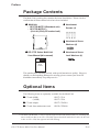
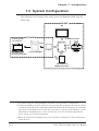
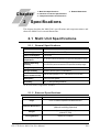
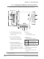
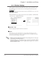
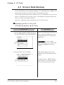
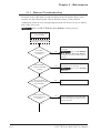
Preface
Thank you for purchasing Digital’s GP-377R Series Multi Unit (hereafter referred
to as the “Multi Unit”). This Multi Unit is installed to the Graphic Control Panel
<Pro-face> GP-377R Series (hereafter referred to as the “GP”) and enables data
input from/output to a CF card, as well as printer output from the GP. In addition,
via the Multi Unit's Ethernet connector, the GP can be connected to an Ethernet
network via a 10BASE-T interface.
This manual describes how to install the Multi Unit, and use it correctly and safely
with the GP. Also, individual manuals have been prepared to explain the use of
each GP. Therefore, be sure to first read “Chapter 1-1 Prior to Operating the GP”
in your GP’s User Manual (sold separately).
<Note>
1) It is forbidden to copy the contents of this manual, in whole or in part, except
for the user’s personal use, without the express permission of the Digital
Electronics Corporation of Japan.
2) The information provided in this manual is subject to change without notice.
3) This manual has been written with care and attention to detail; however, should
you find any errors or omissions, please contact Digital Electronics and inform
them of your findings.
4) Be aware that the Digital Electronics Corporation shall not be held liable for
any real or estimated damages or losses, or third party claims resulting from the
use of this product.
5) The GP377R-MLTE41 is UL/c-UL(CSA) approved and CE marked. However,
installing this unit in a GP unit that is not UL/c-UL(CSA) approved and CE
marked will cause the this unit to lose its UL/c-UL(CSA) approval and CE
marking.
© Copyright 2000, Digital Electronics Corporation. All rights reserved.
All product names mentioned in this manual are the registered trademarks of those
companies.
GP-377R Series Multi Unit User Manual
E-i
Preface
Table of Contents
Preface
............................................................................................... E-i
Table of Contents ...................................................................................E-ii
Essential Safety Precautions ............................................................. E-iv
UL/c-UL(CSA) Application Notes ....................................................... E-vi
CE Marking Notes .................................................................................E-vi
Package Contents ............................................................................... E-vii
Optional Items...................................................................................... E-vii
Compatible Models ............................................................................ E-viii
Documentation Conventions ........................................................... E-viii
Chapter 1 Introduction
1.1
Multi Unit Features ................................................................................ E1-1
1.2
System Configuration ............................................................................. E1-2
1.3
Network Configuration .......................................................................... E1-3
1.3.1
Screen Creation Software Settings ............................................ E1-3
Chapter 2 Specifications
2.1
2.2
Multi Unit Specifications ....................................................................... E2-1
2.1.1
General Specifications................................................................ E2-1
2.1.2
External Specifications............................................................... E2-1
2.1.3
Interface Specifications ............................................................. E2-2
Interface Connector Specifications ...................................................... E2-3
2.2.1
Printer Interface .......................................................................... E2-3
2.3
Component Names and Functions ........................................................ E2-4
2.4
External Dimensions ............................................................................... E2-5
Chapter 3 Installation and Setup
E-ii
3.1
Installing the Multi Unit ........................................................................ E3-1
3.2
CF Card Insertion and Removal .......................................................... E3-2
3.3
Printer Setup............................................................................................ E3-4
GP-377R Series Multi Unit User Manual
Preface
Chapter 4 CF Card
4.1
CF Card Handling .................................................................................. E4-1
4.2
CF Card Initialization ............................................................................ E4-3
4.3
Screen Data Backup ............................................................................... E4-5
Chapter 5 Maintenance
5.1
Troubleshooting ....................................................................................... E5-1
5.1.1
5.2
Ethernet Troubleshooting ........................................................... E5-2
Self-Diagnosis .......................................................................................... E5-4
Index
GP-377R Series Multi Unit User Manual
E-iii
Preface
Essential Safety Precautions
This manual includes procedures that must be followed to operate the Multi Unit
and GP correctly and safely. Be sure to read this manual and any related materials
thoroughly to understand the correct operation and functions of the Multi Unit and
GP.
Symbol Meanings
To indicate the correct use of the Multi Unit and GP, the following symbols are
provided throughout this manual, to indicate operations or procedures requiring
special attention. The following is an example of these symbols and their meanings:
Warning
Incorrect operation resulting from negligence of this instruction may cause death or
serious injury.
Caution
Incorrect operation resulting from negligence of this instruction may cause injury or
damage to equipment.
WARNINGS
When using the Multi Unit and GP, follow the precautions
below:
• Prior to installing and wiring the Multi Unit, confirm that
GP’s power is OFF. Otherwise, an electric shock can occur.
• NEVER attempt to modify or re-design the Multi Unit,
since it can cause a fire or an electric shock.
E-iv
GP-377R Series Multi Unit User Manual
Preface
CAUTIONS
When using the Multi Unit and the GP, be sure to follow the
precautions listed below:
• Be sure not to touch the inner face of the Multi Unit's circuit board.
• Prior to inserting or removing a CF Card, be sure to turn
the Multi Unit’s CF Card ACCESS switch OFF and to confirm that the ACCESS lamp is not lit. If you do not, CF
Card internal data may be destroyed.
• While a CF Card is being accessed, NEVER turn OFF or
reset the GP, or insert or remove the CF Card. Prior to
performing these operations, create and use a special GP
application screen that will prevent access to the CF Card.
Refer to GP-PRO/PB III for Windows Tag Reference Manual
(included in the screen editor software package)
• Be sure to use only CF Cards manufactured by the Digital
Electronics Corporation. Multi Unit performance cannot
be guaranteed when using another manufacturer’s CF
Card.
• Once GP data is lost, it cannot be recovered. Since accidental data loss can occur at any time, be sure to back up
all GP screen and CF card internal data regularly.
To Prevent a Multi Unit Malfunction or Internal Damage:
• Be sure that water, liquids, or metal particles do not enter the Multi Unit, since
it may cause the unit to malfunction, or may cause an electric shock.
• DO NOT store the Multi Unit in a place where it will be exposed to direct
sunlight, high temperatures, excessive dust, or vibration.
• The Multi Unit is precision equipment. DO NOT subject it to excessive shocks.
• DO NOT store the Multi Unit near chemicals, or where chemicals can come
into contact with the unit.
• DO NOT use thinner or organic solvents to clean the metal cover of the Multi
Unit. When this cover becomes dirty or smudged, moisten a soft cloth with
diluted neutral detergent, wring the cloth well, and wipe the cover. NEVER
wipe the Multi Unit's internal circuit board.
• DO NOT touch the Multi Unit’s internal circuit board when handling the unit.
GP-377R Series Multi Unit User Manual
E-v
Preface
UL/c-UL(CSA) Application Notes
The GP377R-MLTE41 is a UL/c-UL(CSA) listed product. (UL file No.E182139)
This unit conforms as a product to the following standards:
UL508
Industrial Control Equipment
UL1604
Electrical Equipment for use in Class I and II, Division 2 and Class III Hazardous
Location, industrial control applications.
CAN/CSA-Nos. 142, and 213-M1987
Standard for Safety of Information Technology Equipment, including Electrical
Business Equipment.
GP377R-MLTE41 (UL Registration Model: 2880048)
<Cautions>
• When the Multi Unit is installed in a GP unit, the combination of the GP and the
Multi Unit must be re-evaluated to receive UL/c-UL approval.
• Be sure that this unit is mounted at least 100 mm (3.94 in.) away from any adjacent
structures or equipment. If these requirements are not met, the heat generated by
the unit's internal components may cause the unit to fail to meet UL/c-UL(CSA)
standard requirements.
UL1604 Compliance Conditions and Handling Cautions:
1. Power, input and output (I/O) wiring must be in accordance with Class I, Division
2 wiring methods - Article 501- 4(b) of the National Electrical Code, NFPA 70
within the United States, and in accordance with Section 18-152 of the Canadian
Electrical Code for units installed within Canada and in accordance with the authority having jurisdiction.
2. Suitable for use in Class I, Division 2, Groups A, B, C and D hazardous or nonhazardous locations only.
3. WARNING: Explosion hazard - substitution of components may impair suitability for Class I, Division 2.
4. WARNING: Explosion hazard - when in hazardous locations, turn power OFF
before replacing or wiring modules.
5. WARNING: Explosion hazard - do not disconnect equipment unless power has
been switched OFF, or the area is known to be non-hazardous.
CE Marking Notes
The GP377R-MLTE41 is a CE marked product that conforms to EMC directives
EN55011 Group1 Class A and EN50082-2.
For detailed CE marking information, contact the Digital Electronics Corporation.
E-vi
GP-377R Series Multi Unit User Manual
Preface
Package Contents
The Multi Unit's packing box contains the items listed below. Please check to
confirm that all items shown below have been included.
Multi Unit
• GP377R-MLTE11(Standard unit)
• GP377R-MLTE41 *1
(UL/c-UL(CSA),CE marked unit)
Attachment
Screws (4)
Attachment Screw
Washers (4)
GP-377R Series Multi Unit
User Manual (this manual)
Attachment Screw
Lock Washers (4)
Digital
Pro-face
GP-377R Series
Multi Unit
User Manual
This unit has been carefully packed, with special attention to quality. However,
should you find anything damaged or missing, please contact your local GP
distributor immediately for prompt service.
Optional Items
The following items are optionally available for the Multi Unit:
CF card (8MB)
(16MB)
GP077-CF10
GP077-CF20
CF card adapter
GP077-CFAD10
CF card front maintenance unit
GP070-CFFM10
*1 The GP377R-MLTE41 is UL/c-UL(CSA) approved and CE marked. However, installing this
unit in a GP unit that is not UL/c-UL(CSA) approved and CE marked will cause the this unit
to lose its UL/c-UL(CSA) approval and CE marking.
GP-377R Series Multi Unit User Manual
E-vii
Preface
Compatible Models
The Multi Unit is designed to be used with the following products:
Compatible GP Units
All GP-377R Series Units
• GP377R-TC11-24V (Standard Units)
• GP377R-TC41-24V (UL/c-UL(CSA),CE marked unit)
Compatible Software
• GP-PRO/PB III for Windows Version 4.0 or higher
• Pro-Server with Pro-Studio for Windows Version 2.0 or higher
Documentation Conventions
This manual uses the following symbols and terminology.
Multi Unit
GP
GP Screen Editor
*1
Indicates GP-377R Series Multi Unit.
Indicates GP-377R Series.
Indicates the GP-PRO/PBIII for Windows Ver. 4.0 or later screen
editor software.
Indicates useful or important supplemental information.
Provides useful or important supplemental information.
Refers to useful or important supplemental information.
E-viii
GP-377R Series Multi Unit User Manual
1. Multi Unit Features
Chapter
1
2. System Configuration
3. Network Configuration
Introduction
This chapter describes the Multi Unit’s functions.
1.1 Multi Unit Features
Using a Multi Unit allows you to perform data input/output from a GP unit to a
CF card, as well as print out data from a GP unit.
For the detailed information about the CF card, refer to the screen editor
software’s manual.
Refer to GP-PRO/PB III for Windows Tag Reference Manual
(contained in the screen editor software package).
Since the Multi Unit is equipped with a 10BASE-T interface, your GP unit can be
connected directly to an Ethernet-compatible PLC or to a personal computer.
Installing this unit in a GP and then connecting it to an Ethernet network allows
the user to exchange their PLC and GP data with a host (PC). Also, the same
Ethernet network can be used to exchange data with and collect data from other
PLCs on the network.
These features allow you to easily create applications for data collection and
exchange.
For information about the 2-Way driver feature,
Refer to Pro-Server with Pro-Studio for Windows Operation Manual
(contained in the Pro-Server with Pro-Studio for Windows software package)
• To use the Multi Unit, the software "GP-PRO/PB III for Windows Version 4.0" or
higher is required.
• To use the 2-way driver, the software "Pro-Server with Pro-Studio for Windows
Version 2.0" or higher is required.
GP-377R Series Multi Unit User Manual
E1-1
Chapter 1 - Introduction
1.2 System Configuration
The following is an example of the entire system configuration when using the
Multi Unit.
ONLINE
GP
OFFLINE
To Ethernet Cable
Insert into the
PC card slot
Multi Unit
Insert
CF Card Adapter
Personal Computer
*1
CF Card
12345
12345
12345
12345
12345
12345
Printer*2
CD Card Front
Maintenance Unit*3
*1 A personal computer running Windows 95/98/NT 4.0 can operate is recommended.
*2 A dedicated Windows printer cannot be used. A printer that recognizes HP Laser Jet PCL 4
commands, NEC PR 201 PL commands, and EPSON ESC/P24-84 commands, or commands
equivalent to these models can be used. Even if a printer is not one of these models, if it has
both Windows and DOS drivers, it may be able to be used. For the detailed information,
please contact your local GP distributor.
*3 When the CF Card Front Maintenance Unit is attached, the Multi Unit's CF Card Interface
cannot be used.
E1-2
GP-377R Series Multi Unit User Manual
Chapter 1 - Introduction
1.3 Network Configuration
The Ethernet network should be created using 10BASE-T. The following is an
example connection layout:
Interface Specifications
Data transmission type:
IEEE802.3
Data transmission speed: 10Mbps
Personal
computer
Twisted pair cable
10BASE-T
concentrator
≈
Ethernet Co-axial
Cable
Transciever
Terminating
resistance
Terminating
resistance
10BASE-T concentrator
Multi Unit
(installed
in GP)
Multi Unit
(installed
in GP)
○
GP
○
○
○
○
○
○
○
○
○
○
○
○
○
○
GP
PLC
1.3.1 Screen Creation Software Settings
When the Multi Unit is being used with an Ethernet network, be sure to choose
either the [Ethernet Compatible PLC], or [MultiLink Ethernet Type] for the screen
creation software's [PLC Type] setting.
Also, when using the 2-Way Driver feature, after setting the [PLC type], be sure to
also select the 2-Way Driver's [2-Way Ether] feature.
In both cases, be sure to also enter all necessary network information, such as IP
addresses, etc.
For detailed information about these features refer to:
GP-PRO/PBIII for Windows Operation Manual (included with screen
creation software), Pro-Server with Pro-Studio for Windows Operation Manual
(included with software)
GP-377R Series Multi Unit User Manual
E1-3
Memo
E1-4
GP-377R Series Multi Unit User Manual
1. Multi Unit Specifications
Chapter
2
4. External Dimensions
2. Interface Connector Specifications
3. Component Names and Functions
Specifications
This chapter describes the Multi Unit’s specifications and component names, and
shows the Multi Unit’s external dimensions.
2.1 Multi Unit Specifications
2.1.1 General Specifications
Item
Description
Rated Voltage
DC5V ±5% (supplied from the GP)
Power Consumption
2.5W or less
Ambient Operating
Temperature
0oC to 40oC (cannot exceed the GP’s specified temperature range)
Ambient Operating
Humidity
30 to 85%RH (cannot exceed the GP’s specified humidity range)
Storage Temperature
-10oC to 60oC
Storage Humidity
30%RH to 85%RH (with no condensation)
Vibration Resistance
(when installed in GP)
10Hz to 25Hz (19.6m/s2 in X, Y, Z directions for 30 minutes)
Atmosphere
Free of corrosive gasses
Grounding
100Ω or less grounding resistance*1
*1 Or your country's applicable standard.
2.1.2 External Specifications
Item
Description
Usage
GP-377R Series expansion slot attachment unit
External Dimensions
Weight
107mm (4.21in.) <W> x 119mm (4.69in.) <H> x 31mm (1.22in.) <D>
(Main unit, excluding projections)
Approximately 400g (881.1b)
(without CF card)
Cooling Method
GP-377R Series Multi Unit User Manual
Natural air circulation
E2-1
Chapter 2 - Specifications
2.1.3 Interface Specifications
Item
CF Card Interface
Printer Interface
10BASE-T Interface
Description
For CF card attachment: 1 slot
ACCESS LED
ACCESS switch
Cornforms to Centronics standards
(Compatible with HP Laserjet PCL4 Commands,
NEC PR201/PL Commands, EPSON ESC/P24-84, or equivalent)
Connector used: RJ-45 (8-pin modular jack)
Input/output specifications: Conforms to IEEE802.3
Data transmission speed: 10Mbps
Recommended cable: Conforms to IEEE802.3
*1
External CF Card interface CF Card Front Maintenance Unit connector
*1 Dedicated Windows printers cannot be used.
E2-2
GP-377R Series Multi Unit User Manual
Chapter 2 - Specifications
2.2 Interface Connector Specifications
2.2.1 Printer Interface
Pin Connection
1
14
25
13
Jack screw: #4-40 (inch)
Pin #
Signal Name
1
PSTB
2
PDB0
3
PDB1
4
PDB2
5
PDB3
6
PDB4
7
PDB5
8
PDB6
9
PDB7
10
NC
11
BUSY
12
NC
13
NC
14
NC
15
NC
16
INIT
17
NC
18
GND
19
GND
20
GND
21
GND
22
GND
23
GND
24
GND
25
GND
Recommended Connector: Dsub25pin plug XM2A-2501 <made by OMRON>
Recommended Cover :
Dsub25pin Cover XM2S-2513<made by OMRON>
Jack Screws XM2Z-0073
GP-377R Series Multi Unit User Manual
<made by OMRON>
E2-3
Chapter 2 - Specifications
2.3 Component Names and Functions
This section describes each Multi Unit component's name and function.
A
With Cover Open
B
E
C
D
F
G
A: CF Card Maintenance Cover
The CF card interface is located
inside this cover.
B: CF Card ACCESS Switch
When this switch is turned ON,
access to the CF card is possible.
C: CF Card ACCESS LED
When the CF card ACCESS switch
is turned ON, this LED lights.
When the ACESS switch is turned
OFF, this LED goes out. The LED is
always lit while the CF card is being
accessed.
D: CF Card*1
CF Card Interface
CF card’s insertion opening.
E: 10BASE-T I/F
Ethernet 10BASE-T interface.
When the power is ON: ON
ACT
(orange) When sending data: Blinks
LINK When linked: ON
(green) When receiving data: Blinks
F: Printer I/F
Printer cable connection interface.
G: EXT. CF Card
CF card front maintenance unit
connector
*1 When the CF Card Front Maintenance Unit is connected, the Multi Unit's CF Card Interface cannot be used.
E2-4
GP-377R Series Multi Unit User Manual
Chapter 2 - Specifications
2.4 External Dimensions
The Multi Unit’s external dimensions are as follows:
31(1.22)
Unit: mm (in.)
119 (4.69)
Top
107 (4.21)
Front
107 (4.21)
119 (4.69)
123 (4.84)
87.5 (3.44)
When attached to the GP-377R
45 (1.77)
155.5 (6.12)
31 (1.22)
87.5 (3.44)
Top
GP-377R Series Multi Unit User Manual
Side
E2-5
Memo
E2-6
GP-377R Series Multi Unit User Manual
1. Installing the Multi Unit
Chapter
3
2. CF Card Insertion and Removal
3. Printer Setup
Installation and Setup
This chapter describes Multi Unit installation, CF Card insertion and removal, and
printer setup.
3.1 Installing the Multi Unit
WARNING
Prior to installing the Multi Unit, be sure to check that the GP’s
power is OFF. Otherwise, it can cause an electric shock.
Prior to attaching the Multi Unit to the GP, be sure to connect the GP’s power cord to
the GP unit. The power cord cannot be attached to the GP after the Multi Unit is
installed.
Peel off the GP-377R expansion connector’s seal.
Secure the Multi Unit in place with its four (4)attachment screws and their
washers (see figure). A torque of only 0.5 to 0.6 N•m is needed.
Exploded
View
GP-377R Series Multi Unit User Manual
E3-1
Chapter 3 - Installation and Setup
3.2 CF Card Insertion and Removal
CAUTIONS
When using the Multi Unit and a CF Card, follow the precautions below:
• Prior to inserting or removing a CF Card, be sure to turn
the Multi Unit’s CF Card ACCESS switch OFF and to confirm that the ACCESS lamp is not lit. If you do not, CF
Card internal data may be damaged or lost.
• While a CF Card is being accessed, NEVER turn OFF or
reset the GP, or insert or remove the CF Card. Prior to
performing these operations, create and use a special GP
application screen that will prevent access to the CF Card.
Refer to GP-PRO/PB III for Windows Tag Reference Manual
(included in the screen editor software package)
• Prior to inserting a CF Card, familiarize yourself with the
CF Card’s front and rear face orientation, as well as the
CF Card connector’s position. If the CF Card is not correctly positioned when it is inserted into the Mulit Unit,
the CF Card’s internal data and the Multi Unit may be
damaged or broken.
• Be sure to use only CF Cards manufactured by the Digital
Electronics Corporation. Multi Unit performance cannot
be guaranteed when using another manufacturer’s CF
Card.
• Once GP data is lost, it cannot be recovered. Since accidental data loss can occur at any time, be sure to back up
all GP screen and CF Card data regularly.
E3-2
GP-377R Series Multi Unit User Manual
Chapter 3 - Installation and Setup
To Insert the CF Card
Loosen the CF Card maintenance cover’s attachment screw and open the cover.
Turn the CF Card ACCESS switch OFF and confirm that the LED is not lit.
Confirm that the CF Card’s orientation is correct, i.e. that the “CF Card” letters
are face up and the small alignment triangle is in the top left corner.
Insert the CF card completely into the insertion slot, until the Eject Button is
pushed outwards.
Turn the CF Card ACCESS switch ON.
Close the CF Card maintenance cover and tighten the cover’s attachment
screw.
Maintenance Cover
CF Card ACCESS Switch
Eject Button
To Remove the CF Card
Loosen the CF Card maintenance cover’s attachment screw and open the cover.
Turn the CF Card ACCESS switch OFF and confirm that the LED is not lit.
Press the Eject button.
Hold the middle of the CF Card and pull it out in a straight line. NEVER tilt it
to one side.
Close the CF Card maintenance cover and tighten the cover’s attachment screw.
GP-377R Series Multi Unit User Manual
E3-3
Chapter 3 - Installation and Setup
3.3 Printer Setup
When a printer is connected to the Multi Unit, printer setup is performed via the
GP’s OFFLINE screen. On this screen, you can designate the printer type and
printing formats.
For the detailed information about the OFFLINE screen, refer to the
GP-377R User Manual.
On the OFFLINE screen, change the tabs in the order of [MAIN]-> [INITIALIZE]
->[SET UP I/O] -> [PRINTER SETUP].
PRINTER TYPE
Select an appropriate printer model to be connected.
PRINT
Select either grey scale (monochrome) or color printing. Selecting grey scale
means that the printing, blue and green, light blue and red, and purple and yellow
will each be printed using the same pattern.
• HP Laser Jet Series printers do not support color printing. Be sure to select grey
scale printing when using this printer.
• When performing grey scale printing, the grey scale colors used will be reduced
from the original 64 colors. Therefore, lightly shaded original colors cannot be
printed, only darker colors.
E3-4
GP-377R Series Multi Unit User Manual
Chapter 3 - Installation and Setup
B/W REVERSE
This setting switches a black attribute to a white attribute, and vice versa. When
this attribute is enabled, and the GP’s background color is black and the display
color is white, the background will be print in white and the display will print in
black.
<e.g.> When the GP’s background color is black and the display color is white:
Enabled
A
Disabled
A
This setting is effective only when printing out screen data. When printing other items,
all data will be printed with a black background, regardless of this setting.
GP-377R Series Multi Unit User Manual
E3-5
Memo
E3-6
GP-377R Series Multi Unit User Manual
1. CF Card Handling
2. CF Card Initialization
Chapter
4
3. Screen Data Backup
CF Card
This chapter describes the precautions required when handling the CF Card, as
well as the CF Card functions available when using the GP.
4.1 CF Card Handling
CAUTIONS
• Be sure to use only CF Cards manufactured by the Digital
Electronics Corporation. Multi Unit performance cannot
be guaranteed when using another manufacturer’s CF
Card.
• Be sure to follow the instructions given below to prevent
the CF Card’s internal data from being destroyed or a CF
Card malfunction from occuring:
• DO NOT bend the CF Card.
• DO NOT drop or strike the CF Card against another
object.
• Keep the CF Card dry.
• DO NOT touch the CF Card or Multi Unit connectors.
• DO NOT disassemble or modify the CF Card.
The CF Card has a data overwrite limit of approximately 100,000 times. Therefore, be sure to back up all CF Card data regularly to another storage media.
(100,000 times assumes the overwriting of 500KB of data in DOS format)
To view a CF Card’s data on a personal computer, first, insert the CF Card into a
CF Card Adapter. Then, insert the adapter into your personal computer’s PC card
slot. Depending on your model personal computer, the CF Card’s data may not be
able to be read correctly. Please contact your local GP distributor for a list of the
latest CF Card and personal computer operation test results.
GP-377R Series Multi Unit User Manual
E4-1
Chapter 4 - CF Card
If your personal computer is not equipped with a PC card slot, please use a standard type PC Card or CF Card reader. All of Digital’s CF Card operation testing
has been performed using the following equipment.
Manufacturer Name
Model
Connection Type
I-O DAT A DEVICE, INC.
CardDock-CF/P
Parallel port
The connection between a personal computer and CF Card reader has been tested
using an IBM compatible machine. This does not mean, however, that any IBM
compatible machine can be used. Please contact your PC or CF Card reader
manufacturer directly for details.
E4-2
GP-377R Series Multi Unit User Manual
Chapter 4 - CF Card
4.2 CF Card Initialization
Here, the CF Card’s initialization method is described. To perform initialization,
however, the GP needs to have its system data downloaded from your PC via the
screen editor software.
Be sure to use the following steps when initializing the CF Card.
PROCEDURE
REMARKS
Select [INITIALIZE] from the GP
OFFLINE mode’s MAIN MENU.
Prior to starting operation, attach the
Multi Unit to the GP and insert the
CF Card into the Multi Unit.
For instructions on how to enter
OFFLINE mode, refer to the GP377R Series User Manual (sold
separately).
Select [INITIALIZE MEM]
Select [INITIALIZE CF-CARD].
If the Multi Unit is not attached to
the GP, this menu will not be displayed.
GP-377R Series Multi Unit User Manual
E4-3
Chapter 4 - CF Card
PROCEDURE
Enter the password using the numeric
keys provided on the screen.
Press the
button, and the CF Card’s
initialization will start.
REMARKS
Enter the password registered in the
screen editor software’s [GP System
Settings] screen, or in the GP’s
OFFLINE mode. If a password has
not been registered yet, enter “1101”.
Refer to GP-PRO/PB
III for Windows Operation Manual
(included in the screen editor software package) or each GP’s User
Manual (sold separately from the
GP).
When initialization is completed, the GP’s
display will return to the screen shown in
step 3.
CF Card initialization erases all the data stored in the CF Card.
When the CF Card is initialized via the Mulit Unit, a folder is created automatically. Data transferred to the CF Card is then stored in the following files.
Folder
Data Type
\file
\log
Filing Data
Logging data
Image screen data
Sound data
GP backup data (MRM file)
Trend graph data
Sampling data
Alarm data
- Active or Block 1 data
- History or Block 2 data
- Log or Block 3 data
\data
\mrm
\trend
\alarm
File Name
ZF*****.BIN
ZL*****.CSV
ZI*****.BIN
ZO*****.BIN
ZC00001.MRM (fixed)
ZT*****.CSV
ZS*****.CSV
ZA*****.CSV
ZH*****.CSV
ZG*****.CSV
• CF Card data file names must be 8 characters or less. These file names, however,
are not compatible with the FAT32 file naming system.
• When storing new data in a CF Card that will require the overwriting of old data,
the CF Card’s available capacity (free space) must be larger than the size of data
to be stored, since the new data is written before the old data is deleted.
E4-4
GP-377R Series Multi Unit User Manual
Chapter 4 - CF Card
4.3 Screen Data Backup
Screen data backup can be performed using a CF Card backup file (*.MRM). This
backup data can also be copied to another GP unit and used there.
This section explains how to back up data to the CF Card and how to copy screen
data to a GP that has be previously setup, i.e. has had all its required system data
sent to it via the screen editor software.
Only one (1) data file can be backed up to the CF Card at a time.
Backing Up a File to a CF Card
(GP internal memory → CF Card)
PROCEDURE
Select [TRANSFER SCREEN DATA] in
the GP OFFLINE mode’s MAIN MENU.
REMARKS
Before performing this procedure, be
sure to attach the Multi Unit to the
GP and insert the CF Card into the
Multi Unit.
To enter the GP
OFFLINE mode, refer to GP-377R
Series User Manual (sold separately).
Select [COPY TO CF-CARD]
If the Multi Unit has not been attached to the GP, this menu will not
appear.
If a backup file (*. MRM) already
exists in the CF Card, that data will
be overwritten by your new data.
GP-377R Series Multi Unit User Manual
E4-5
Chapter 4 - CF Card
PROCEDURE
REMARKS
Use the screen’s numeric keys to enter the
password.
Be sure to enter the password registered in the screen editor software’s
[Screen Transfer] area. If a password
has not been registered yet, enter
“1101”.
Refer to GP-PRO/PB
III for Windows Operation Manual
(included in the screen editor software package)
Press the
button to start copying data
to the CF Card.
While data is being copied to the CF
Card, DO NOT turn OFF or reset the
GP.
When copying is completed, the GP’s
display will return to the screen shown in
step 2.
E4-6
GP-377R Series Multi Unit User Manual
Chapter 4 - CF Card
Copying a Backup File from the CF Card to the GP
(CF Card → GP internal memory)
PROCEDURE
Select [TRANSFER SCREEN DATA] in
the GP OFFLINE mode’s MAIN MENU.
REMARKS
Prior to starting operation, install the
Multi Unit in the rear of the GP and
insert a CF Card into the Multi Unit.
To enter the GP’s
OFFLINE mode, refer to GP-377R
Series User Manual (sold separately).
Select [COPY FROM CF-CARD].
When the [COPY FROM CFCARD] is performed, data stored in
the backup SRAM will be erased.
If the protocol downloaded to the
destination GP is different from the
protocol for the file to be copied, an
error message “Applicable PLC has
not been set up” will appear. Be sure
to only copy a backup file with the
same protocol as the GP.
Enter the password using the GP screen’s
numeric keys.
Press the
button to start the copying
of the data to the CF Card.
Enter the password registered in the
screen editor software’s [GP System
Settings] screen, or in the GP’s
OFFLINE mode. If a password has
not been registered yet, enter “1101”.
Refer to GP-PRO/PB
III for Windows Operation Manual
(contained in the screen editor
software package) or GP-377R
Series User Manual (sold separately).
While data is being copied to the CF
Card, DO NOT turn OFF or reset the
GP.
GP-377R Series Multi Unit User Manual
E4-7
Memo
E4-8
GP-377R Series Multi Unit User Manual
1. Troubleshooting
2. Self-Diagnosis
Chapter
5
Maintenance
This chapter describes the Multi Unit’s maintenance procedures.
5.1 Troubleshooting
Here, only problems related to the Multi Unit are discussed.
For Ethernet-related troubleshooting, refer to 5.1.1 Ethernet Troubleshooting.
WARNING
Prior to attaching or wiring the Multi Unit, confirm that both
the GP and the Multi Unit power cords are disconnected
from the main power supply. Otherwise, an electric shock
may occur.
Multi Unit Problems and Countermeasures
Problem
Countermeasures
Check if the Multi Unit has been installed to the GP
correctly.
Cannot access the Check if the CF card has been inserted into the
CF card
Multi Unit correctly.
Check if the CF card ACCESS switch has been
turned ON.
Check if the Multi Unit has been installed to the GP
correctly.
Check if the printer has been connected to the GP
Cannot print
correctly.
Check if the GP OFFLINE mode's printer settings
are correct.
GP-377R Series Multi Unit User Manual
E5-1
Chapter 5 - Maintenance
5.1.1 Ethernet Troubleshooting
If trouble occurs while data is being sent between the GP and the Host via the
network, use the following flow chart to find the cause(s) of the problem.
Additionally, when an error message appears on the GP screen, be sure to make a
note of the error code.
Refer to GP-377R Series User Manual (sold separately).
Network communication
is not possible
Disconnect the GP, Host and
Concentrator power cords
Is the PLC
type designated
correctly?
Be sure the correct PLC type has been
designated.
No
Refer to GP-PRO/PB
III for Windows Operation Manual
(included in the screen editor software
package).
Yes
Has the Multi
Unit been attached
correctly?
No
Reattach the Multi Unit and tighten the
attachment screws securely.
Refer to 3.1 Installing
Multi Unit
Yes
Have any Multi
Unit connector pins been
bent or broken?
Yes
Please contact your local GP distributor.
No
Has all Ethernet
wiring been set up
correctly?
No
Correct all Ethernet wiring and attach
check that all Ethernet connectors are
securely attached.
Yes
E5-2
GP-377R Series Multi Unit User Manual
Chapter 5 - Maintenance
Reconnect the GP and
Concentrator power cords
and turn both units ON
Are all the Ethernet
settings correct?
No
Check that all Ethernet settings are
correct.
Yes
Is the [LINK]
LED lit?
Yes
No
Is the [ACT]
LED lit?
Yes
Yes
No
Replace the Multi Unit with a
new one.
Please contact your local GP
distributor.
Are all
Screen data
settings correct?
No
Refer to GPPRO/PB III for Windows Tag
Reference Manual (included in
the screen editor software
package).
Yes
Reconnect the Host
unit’s power cord and
turn it ON.
Yes
Is network
communication performed
correctly?
Is the ACT
LED blinking?
Check the Screen data and reset
it, if necessary.
No
Check the Host’s settings.
Yes
No
Does an
error occur during
self-diagnosis?
No
Check the Host’s settings.
Yes
The original Multi
Unit is defective.
Please contact your
local GP distributor.
The GP is defective.
Please contact your
local GP distributor.
GP-377R Series Multi Unit User Manual
The new Multi Unit is
defective.
Please contact your
local GP distributor.
E5-3
Chapter 5 - Maintenance
5.2 Self-Diagnosis
After the Multi Unit is installed in the rear of the GP, the Multi Unit self-diagnosis
selection will be added to the GP OFFLINE mode’s self-diagnosis menu. Here,
self-diagnosis items related to the Multi Unit are described.
For the detailed information about the OFFLINE mode and the selfdiagnosis feature, refer to the GP-377R Series User Manual (sold separately).
The Multi Unit’s self-diagnosis includes the following items:
• Communication check (SIO CHECK)
• CF card check (CF-CARD CHECK)
• CF card check sum (CF-CARD CHECKSUM; inside CF-CARD CHECK )
• Printer interface check (PRINTER I/F)
To display this screen, the GP needs to have system information sent to it via your
PC’s screen editor software. Items related to the Multi Unit will be displayed only
after the Multi Unit is attached to the GP.
E5-4
GP-377R Series Multi Unit User Manual
Chapter 5 - Maintenance
Communication Check
This feature checks if communication over the Ethernet network is being performed normally. To use this self-diagnosis feature, first connect a Concentrator
and the Ethernet cable.
Press the
button in the [SELF-DIAGNOSIS MENU].
If all communication conditions are normal, both “OK” and the ethernet address will display. If not, an error message will display.
CF Card Check
This feature checks the data read/write to the CF card. To perform this check a CF
card is required, with more than 1KB of free space.
Press the
button in the [SELF-DIAGNOSIS MENU].
Press the
button in the [CF CARD] menu.
Confirm that the CF card has been inserted into the Multi Unit and press the
button.
If the CF card’s data read/write feature is normal, “OK” will display. If not, an
error message will display.
GP-377R Series Multi Unit User Manual
E5-5
Chapter 5 - Maintenance
CF Card Check Sum
This uses the CF card file’s check sum feature to check the CF card. To perform
this check, a CF card must be inserted into the Multi Unit.
File types that can be checked are:
• Filing data
• CF card’s image screen data
• CF card’s sound data
Press the
button in the [SELF-DIAGNOSIS MENU].
Press the
button in the [CF CARD] menu.
Confirm that the CF card has been inserted into the Multi Unit and press the
button.
After the check is completed, the number of checked files, number of error
files, and the file name that last became an error will display.
Printer Interface Check
This checks the printer interface. To perform this check, a printer cable must be
attached to the Multi Unit’s PRINTER connector.
Press the
button in the [SELF-DIAGNOSIS MENU].
Confirm that the printer, printer cable and Multi Unit are all connected and
press
.
If the printer interface is operating normally, the characters “20h to 7D” and
“A0h to DFh” will be printed and “OK” will appear on the screen. If not, an
error message will appear.
E5-6
GP-377R Series Multi Unit User Manual
Index
Characters
10BASE-T ....................................................... E-i
10BASE-T concentrator ............................... E1-3
10BASE-T interface .......................... E1-1, E2-4
2-Way Driver ..................................... E1-1, E1-3
A
ACCESS lamp ..................................... E-v, E3-2
alignment triangle ......................................... E3-3
Attachment Lock Washers ............................ E-vii
Attachment Washers ..................................... E-vii
Attachment Screw ................... E-vii, E3-1, E3-3
available capacity (free space) ...................... E4-4
B
B/W Reverse ................................................. E3-5
Backing Up a File ......................................... E4-5
C
CAUTIONS .............................. E-v, E3-2, E4-1
CD Card Front Maintenance Unit ................. E1-2
CE Marking Notes ......................................... E-vi
CF Card .... E-v, E-vii, E1-1, E2-4, E3-2, E4-4
CF Card ACCESS LED ................................ E2-4
CF Card ACCESS Switch .................... E-v, E2-4
CF Card ACCESS switch OFF ..................... E3-2
CF Card Adapter ..................... E-vii, E1-2, E4-1
CF Card Check ............................................. E5-5
CF Card Check Sum ..................................... E5-6
CF Card Front Maintenance Unit ................. E-vii
CF Card Handling ......................................... E4-1
CF Card Initialization ................................... E4-3
CF Card Insertion ......................................... E3-3
CF Card Insertion and Removal ................... E3-2
CF Card Maintenance Cover ........................ E2-4
CF Card malfunction .................................... E4-1
CF Card reader ............................................. E4-2
CF Card Removal ......................................... E3-3
Communication Check .................................. E5-5
Compatible GP Units .................................. E-viii
Compatible Models .................................... E-viii
Compatible Software .................................. E-viii
Component Names and Functions ................ E2-4
GP-377R Series Multi Unit User Manual
Copying ........................................................ E4-7
D
data copying .................................................. E4-6
data file names .............................................. E4-4
death or serious injury ................................... E-iv
Dedicated Windows printers ......................... E2-2
Documentation Conventions ....................... E-viii
E
electric shock ...................................... E-iv, E3-1
error code ...................................................... E5-2
error message .......................... E4-7, E5-5, E5-6
Essential Safety Precautions .......................... E-iv
Ethernet Co-axial Cable ................................ E1-3
Ethernet connector ........................................... E-i
Ethernet Troubleshooting ............................. E5-2
Ethernet-compatible PLC ............................. E1-1
Ethernet-related troubleshooting .................. E5-1
EXT. CF Card ............................................... E2-4
External Dimensions ..................................... E2-5
External Specifications ................................. E2-1
F
FAT32 ........................................................... E4-4
G
General Specifications .................................. E2-1
GP data ......................................................... E3-2
grey scale printing ......................................... E3-4
I
INITIALIZE ................................................. E4-3
injury or damage to equipment ...................... E-iv
Installing the Multi Unit ............................... E3-1
Interface Specifications ............................... E2-2
Interface Connector Specifications ............... E2-3
Interface Specifications ................................ E1-3
L
local GP distributor ....................................... E4-1
Index-i
M
U
Maintenance Cover ....................................... E3-3
Multi Unit connector .................................... E4-1
Multi Unit Features ....................................... E1-1
Multi Unit Problems ..................................... E5-1
Multi Unit Specifications .............................. E2-1
Multi Unit's internal circuit board ................... E-v
MultiLink Ethernet Type .............................. E1-3
UL/c-UL(CSA) Application Notes ................ E-vi
W
WARNING ................................................... E3-1
WARNINGS ....................................... E-iv, E5-1
washers ......................................................... E3-1
N
Network Configuration ................................. E1-3
O
OFFLINE ...................................................... E1-2
ONLINE ....................................................... E1-2
Optional Items .............................................. E-vii
overwrite limit .............................................. E4-1
P
Package Contents .......................................... E-vii
password ....................................................... E4-6
power cord .................................................... E5-1
precautions ..................................................... E-iv
Print .............................................................. E3-4
Printer ........................................................... E1-2
Printer Type ................................................. E3-4
Printer I/F ...................................................... E2-4
Printer Interface Check ................................. E5-6
Printer Setup ................................................. E3-4
Pro-face ............................................................ E-i
R
Recommended Connector ............................. E2-3
S
Safty Precautions ........................................... E-iv
Screen Data Backup ...................................... E4-5
Self-Diagnosis ............................................... E5-4
System Configuration ................................... E1-2
T
Tool Connector ............................................. E3-4
torque ............................................................ E3-1
Troubleshooting ............................................ E5-1
Twisted pair cable ......................................... E1-3
Index-ii
GP-377R Series Multi Unit User Manual


![Rockwell (Allen-Bradley) PLCs [Ethernet Communication] - Pro](http://vs1.manualzilla.com/store/data/005902559_1-37f0d35b01d224110d582dd04f222df0-150x150.png)