1
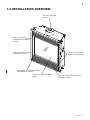
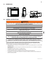
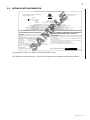
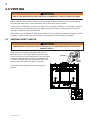
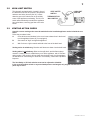
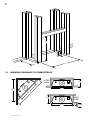
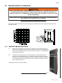
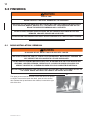
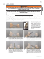
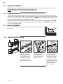
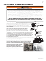
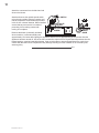
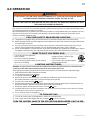
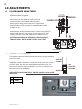
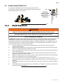
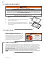
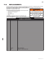
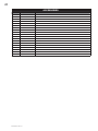
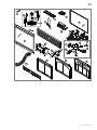
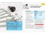
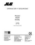
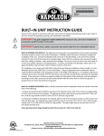
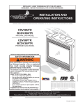
1 INSTALLER: LEAVE THIS MANUAL WITH THE APPLIANCE. CONSUMER: RETAIN THIS MANUAL FOR FUTURE REFERENCE. INSTALLATION AND OPERATING INSTRUCTIONS CERTIFIED UNDER CANADIAN AND AMERICAN NATIONAL STANDARDS: CSA 2.22, ANSI Z21.50 RESPECTIVELY FOR VENTED GAS FIREPLACES. BCNV36N NATURAL GAS MODEL BCNV36P PROPANE GAS MODEL CERTIFIED FOR CANADA AND UNITED STATES USING ANSI/CSA METHODS. SAFETY INFORMATION ! WARNING If the information in these instructions are not followed exactly, a fire or explosion may result causing property damage, personal injury or loss of life. - Do not store or use gasoline or other flammable vapors and liquids in the vicinity of this or any other appliance. - WHAT TO DO IF YOU SMELL GAS: • Do not try to light any appliance. • Do not touch any electrical switch; do not use any phone in your building. • Immediately call your gas supplier from a neighbour’s phone. Follow the gas supplier’s instructions. • If you cannot reach your gas supplier, call the fire department. - Installation and service must be performed by a qualified installer, service agency or the supplier. ! WARNING HOT GLASS WILL CAUSE BURNS. DO NOT TOUCH GLASS UNTIL COOLED. NEVER ALLOW CHILDREN TO TOUCH GLASS. Wolf Steel Ltd., 24 Napoleon Rd., Barrie, ON, L4M 0G8 Canada / 103 Miller Drive, Crittenden, Kentucky, USA, 41030 Phone (705)721-1212 • Fax (705)722-6031 • www.continentalfireplaces.com • [email protected] $10.00 1.31 W415-0861 / A / 02.10.11 2 TABLE OF CONTENTS 1.0 2.0 3.0 4.0 5.0 6.0 7.0 8.0 9.0 10.0 11.0 12.0 13.0 14.0 INSTALLATION OVERVIEW INTRODUCTION 3 4 2.1 2.2 2.3 2.4 5 5 6 7 DIMENSIONS GENERAL INSTRUCTIONS GENERAL INFORMATION RATING PLATE INFORMATION VENTING 8 3.1 3.2 3.3 8 9 9 VENTING SAFETY SWITCH HIGH LIMIT SWITCH VENTING ACTION CHECK INSTALLATION 10 4.1 4.2 10 10 GAS INSTALLATION OPTIONAL WALL SWITCH / THERMOSTAT FRAMING 11 5.1 5.2 5.3 12 13 13 MINIMUM CLEARANCE TO COMBUSTIBLES MINIMUM MANTEL CLEARANCES NAILING TAB INSTALLATION FINISHING 14 6.1 6.2 6.3 6.4 6.5 6.6 14 15 16 16 16 16 DOOR INSTALLATION / REMOVAL LOG PLACEMENT CHARCOAL EMBERS GLOWING EMBERS LOGO PLACEMENT LOUVRE INSTALLATION OPTIONAL BLOWER INSTALLATION OPERATION ADJUSTMENTS 17 19 20 9.1 9.2 9.3 20 20 21 PILOT BURNER ADJUSTMENT VENTURI ADJUSTMENT FLAME CHARACTERISTICS MAINTENANCE 21 10.1 10.2 10.3 22 22 22 DOOR GLASS REPLACEMENT CARE OF GLASS CARE OF PLATED PARTS REPLACEMENTS TROUBLE SHOOTING WARRANTY SERVICE HISTORY NOTE: Changes, other than editorial, are denoted by a vertical line in the margin. W415-0861 / A / 02.10.11 23 26 28 29 3 1.0 INSTALLATION OVERVIEW Vent, see “VENTING” section. Glass, see “DOOR GLASS REPLACEMENT” section. Logo, see “LOGO PLACEMENT” section. Louvres, see “LOUVRE INSTALLATION” section. Rating plate, see “RATING PLATE INFORMATION” section. Logs, see “LOG PLACEMENT” section. Door, see “DOOR INSTALLATION / REMOVAL” section. W415-0861 / A / 02.10.11 4 2.0 INTRODUCTION ! • • • • • • • • • • • • • • • • • • • • • • • • • • • WARNING THIS APPLIANCE IS HOT WHEN OPERATED AND CAN CAUSE SEVERE BURNS IF CONTACTED. ANY CHANGES OR ALTERATIONS TO THIS APPLIANCE OR IT’S CONTROLS CAN BE DANGEROUS AND IS PROHIBITED. Do not operate appliance before reading and understanding operating instructions. Failure to operate appliance according to operating instructions could cause fire or injury. Risk of fire or asphyxiation do not operate appliance with fixed glass removed. Do not connect 110 volts to the control valve. Risk of burns. The appliance should be turned off and cooled before servicing. Do not install damaged, incomplete or substitute components. Risk of cuts and abrasions. Wear protective gloves and safety glasses during installation. Sheet metal edges may be sharp. Do not burn wood or other materials in this appliance. Children and adults should be alerted to the hazards of high surface temperature and should stay away to avoid burns or clothing ignition. Toddlers, young children and others may be susceptible to accidental contact burns. A physical barrier is recommended if there are at risk individuals in the house. To restrict access to an appliance or stove, install an adjustable safety gate to keep toddlers, young children and other at risk individuals out of the room and away from hot surfaces. Clothing or other flammable material should not be placed on or near the appliance. Due to high temperatures, the appliance should be located out of traffic and away from furniture and draperies. Ensure you have incorporated adequate safety measure to protect infants/toddlers from touching hot surfaces. Even after the appliance is out, the glass and/or screen will remain hot for an extended period of time. Check with your local hearth specialty dealer for safety screens and hearth guards to protect children from hot surfaces. These screens and guards must be fastened to the floor. Any safety screen or guard removed for servicing must be replaced prior to operating the appliance. This appliance is a vented gas-fired appliance. Do not burn wood or other materials in this appliance. It is imperative that the control compartments, burners and circulating blower and its passageway in the appliance and venting system are kept clean. The appliance and its venting system should be inspected before use and at least annually by a qualified service person. More frequent cleaning may be required due to excessive lint from carpeting, bedding material, etc. The appliance area must be kept clear and free from combustible materials, gasoline and other flammable vapors and liquids. Under no circumstances should this appliance be modified. This appliance must not be connected to a chimney flue pipe serving a separate solid fuel burning appliance. Do not use this appliance if any part has been under water. Immediately call a qualified service technician to inspect the appliance and to replace any part of the control system and any gas control which has been under water. Do not operate the appliance with the glass door removed, cracked or broken. Replacement of the glass should be done by a licensed or qualified service person. Do not strike or slam shut the appliance glass door. Only doors / optional fronts certified with the unit are to be installed on the appliance. Keep the packaging material out of reach of children and dispose of the material in a safe manner. As with all plastic bags, these are not toys and should be kept away from children and infants. As with any combustion appliance, we recommend having your appliance regularly inspected and serviced as well as having a Carbon Monoxide Detector installed in the same area to defend you and your family against Carbon Monoxide. Ensure clearances to combustibles are maintained when building a mantel or shelves above the appliance. Elevated temperatures on the wall or in the air above the appliance can cause melting, discolouration or damage to decorations, a T.V. or other electronic components. 3.16B W415-0861 / A / 02.10.11 5 2.1 DIMENSIONS 36 3/4" 27" 4" DIA. 32 3/8" 5 1/2" GAS INLET 12 1/4" 7 1/4" 3" ELECTRICAL INLET LEFT SIDE 2.2 13 1/4" 18" 36" GENERAL INSTRUCTIONS ! WARNING ALWAYS LIGHT THE PILOT WHETHER FOR THE FIRST TIME OR IF THE GAS SUPPLY HAS RUN OUT, WITH THE GLASS DOOR OPENED OR REMOVED. PROVIDE ADEQUATE CLEARANCE FOR SERVICING AND OPERATING THE APPLIANCE. PROVIDE ADEQUATE VENTILATION. NEVER OBSTRUCT THE FRONT OPENING OF THE APPLIANCE. OBJECTS PLACED IN FRONT OF THE APPLIANCE MUST BE KEPT A MINIMUM OF 48” FROM THE FRONT FACE OF THE UNIT. SURFACES AROUND AND ESPECIALLY ABOVE THE APPLIANCE CAN BECOME HOT. AVOID CONTACT WHEN THE APPLIANCE IS OPERATING. FIRE RISK. EXPLOSION HAZARD. HIGH PRESSURE WILL DAMAGE VALVE. DISCONNECT GAS SUPPLY PIPING BEFORE PRESSURE TESTING GAS LINE AT TEST PRESSURES ABOVE 1/2 PSIG. CLOSE THE MANUAL SHUT-OFF VALVE BEFORE PRESSURE TESTING GAS LINE AT TEST PRESSURES EQUAL TO OR LESS THAN 1/2 PSIG. USE ONLY WOLF STEEL APPROVED OPTIONAL ACCESSORIES AND REPLACEMENT PARTS WITH THIS APPLIANCE. USING NON-LISTED ACCESSORIES (BLOWERS, DOORS, LOUVRES, TRIMS, GAS COMPONENTS, VENTING COMPONENTS, ETC.) COULD RESULT IN A SAFETY HAZARD AND WILL VOID THE WARRANTY AND CERTIFICATION. THIS GAS APPLIANCE SHOULD BE INSTALLED AND SERVICED BY A QUALIFIED INSTALLER to conform with local codes. Installation practices vary from region to region and it is important to know the specifics that apply to your area, for example in Massachusetts State: • This product must be installed by a licensed plumber or gas fitter when installed within the commonwealth of Massachusetts. • The appliance damper must be removed or welded in the open position prior to installation of a appliance insert or gas log. • The appliance off valve must be a “T” handle gas cock. • The flexible connector must not be longer than 36 inches. • A Carbon Monoxide detector is required in all rooms containing gas fired appliances. • The appliance is not approved for installation in a bedroom or bathroom unless the unit is a direct vent sealed combustion product. W415-0861 / A / 02.10.11 6 The installation must conform with local codes or, in absence of local codes, the National Gas and Propane Installation Code CSA B149.1 in Canada, or the National Fuel Gas Code, ANSI Z223.1 / NFPA 54 in the United States. Suitable for mobile home installation if installed in accordance with the current standard CAN/CSA Z240MH Series, for gas equipped mobile homes, in Canada or ANSI Z223.1 and NFPA 54 in the United States. www.nficertified.org We suggest that our gas hearth products be installed and serviced by professionals who are certified in the U.S. by the National Fireplace Institute® (NFI) as NFI Gas Specialists As long as the required clearance to combustibles is maintained, the most desirable and beneficial location for an appliance is in the center of a building, thereby allowing the most efficient use of the heat created. The location of windows, doors and the traffic flow in the room where the appliance is to be located should be considered. If possible, you should choose a location where the vent will pass through the house without cutting a floor or roof joist. If the appliance is installed directly on carpeting, vinyl tile or other combustible material other than wood flooring, the appliance shall be installed on a metal or wood panel extending the full width and depth. Some appliances have optional fans or blowers. If an optional fan or blower is installed, the junction box must be electrically connected and grounded in accordance with local codes, use the current CSA C22.1 Canadian Electrical Code in Canada or the ANSI/NFPA 70 National Electrical code in the United States. 4.1A 2.3 GENERAL INFORMATION FOR YOUR SATISFACTION, THIS APPLIANCE HAS BEEN TEST-FIRED TO ASSURE ITS OPERATION AND QUALITY! BCNV36 NG LP 0-4,500 0-4,500 17,000 BTU/hr 17,000 BTU/hr Min. Inlet Gas Supply Pressure 4.5" Water Column 11" Water Column Max. Inlet Gas Supply Pressure 7" Water Column 13" Water Column 3.5" Water Column 10" Water Column Altitude (FT) Max. Input (BTU/HR) Manifold Pressure (Under Flow Conditions) When the appliance is installed at elevations above 4,500 ft, and in the absence of specific recommendations from the local authority having jurisdiction, the certified high altitude input rating shall be reduced at the rate of 4% for each additional 1,000 ft. Expansion / contraction noises during heating up and cooling down cycles are normal and to be expected. This appliance is approved for bedroom and bed-sitting room installation. No external electricity (110 volts or 24 volts) is required for the gas system operation. W415-0861 / A / 02.10.11 7 RATING PLATE INFORMATION CERTIFIED UNDER / HOMOLOGUE SELON LES NORMES: CSA 2.22b-2009 & ANSI Z21.50b-2009. 21.50b 21.5 0b-200 -20 VENTED GAS FIREPLACE. APPROVED FOR BEDROOM, AND BED-SITTING ROOM INSTALLATION. FOYER HOMOLOGUE POUR INSTALLATION OYER A GAZ GA VENTILE. HOM DANS UNE CHAMBRE A COUCH COUCHER, ET UN STUDIO. S A M P LE 2.4 MODEL MODEL M O DE DELL BGNV36N / BCNV36N 0-4500FT (0-1370m) 17,000 BTU/h 12,000BTU/h BGNV36P / B BCNV36P ALTITUDE / ELEVATION TIO ON INPUT / ALIMENTATION TATION TA REDUCED INPUT / ALIMENTATION EN NTATION TIO REDUITE EDUITE MANIFOLD PRESSURE: 3.5" WATER COLUMN MN N PRESSION AU COLLECTEUR: 3.5" D'UNE COLONNE D'EAU 'EAU EAU MINIMUM SUPPLY PRESSURE: 4.5" WATER COLUMN OLUM UMN N PRESSION D'ALIMENTATION MINIMALE: 4.5" D'UNE COLONNE NE D'EAU AU MAXIMUM SUPPLY PRESSURE: 7.0" WATER COLUMN ER COLUM COLU N PRESSION D'ALIMENTATION MAXIMALE: 7.0" D'UNE COLONNE OLONNE LONNE D'EAU D'EA NOT FOR USE WITH SOLID FUEL. FOR USE WITH H GLAS GLASS S DOORS CERTIFIED WITH THIS UNIT ONLY. Y.. Y WARNING: DO NOT ADD ANY MATERIAL TO THE APPLIANCE, CE, WHICH WIL WILL L COME IN CON CON-- TACT WITH THE FLAMES, OTHER THAN THAT SUPPLIED BY Y THE MANU MANUFACTURER UFACTURER WITH TH THE E APPLIANCE. MINIMUM CLEARANCE TO COMBUSTIBLE MATERIALS MA ATERIALS / DEGAGEMENTS MINIMAUX DES MATERIAUX AUX XC COMBUSTIBLES: OMBUSTIB STIBL LES ES:: TOP/ DESSUS FLOOR / PLANCHER SIDES / COTES BACK / ARRIERE 0 0 0 0 RECESSED DEPTH TH / PROFONDEUR OFONDEUR D'ENCASTRE VENT / EVENT MANTLE / MANTEAU 13½" 1" 2" * * MAXIMUM HORIZONTAL EXTENSION SION / L'EXTENSION L'EXTENSIO HORIZON HORIZONTALE RIZONT TALE A M MAXIMALE: 2". 0-4500FT 500FT (0-1370m) (0-13 0-13 17,000 7,000 BTU/h BTU BTU/ 12,000BTU/h 12,000BT MANIFOLD PRESSURE: 10" W WATER COLUMN PRESSION AU A COLLECTEU COLLECTEUR: ECTEU 10" D'UNE COLONNE D'EAU MINIMUM SUPP S SUPPLY L PRESS LY PRESSURE: 11" WATER COLUMN PRESSIO D'ALIMENT PRESSION D'ALIMENTATION MINIMALE: 11" D'UNE COLONNE D'EAU MAXIMU SUPPLY MAXIMUM L P PRESSURE: 13" WATER COLUMN PRESSION D'ALIMENTATION D'ALIM MAXIMALE: 13" D'UNE COLONNE D'EAU UN N COM COMBUSTIBLE SOLIDE NE DOIT PAS ETRE UTILISE AVEC AVEC CET APPAREIL. UTILISER AVEC LES PORTES VITREES HOMOLOGUEES HO HOM SEULEMENT AVEC CETTE UNITE. AVERTISSEMENT: N'AJOUTEZ PAS A CET APPAREIL AUCUN MATERIAU DEVANT ENTRER EN CONTACT AVEC LES FLAMMES AUTRE QUE CELUI QUI EST FOURNI AVEC CET APPAREIL PAR LE FABRICANT. THE APPLIANCE MUST BE VENTED USING "B" VENT. SEE OWNERS INSTALLATION MANUAL FOR VENTING SPECIFICS. L'APPAREIL DOIT EVACUER SES GAZ EN UTILISANT L'EVENT "B". REFERER AU MANUEL D'INSTALLATION DE PROPRIETAIRE POUR L'EVACUATION PRECISE. ELECTRICAL RATING / CLASSIFICATION: 115V 0.82AMP, 60HZ OPTIONAL FAN KIT / ENSEMBLE DE VENTILATEUR FACULTATIF: GZ550-KT L FOR FO R GREATER G RE E AT ER EXTENSIONS. EXT EX T ENS EN IO IONS NS.. REFERER R SEE INSTRUCTION MANUAL AU MANUEL TEN NSIO SION NS PLUS PLU LUS SG RAND NDES E . D'INSTRUCTION POUR DES EXTE EXTENSIONS GRANDES. WOLF STEEL LTD. 24 Napoleon Rd. Barrie, Ontario L4M 4Y8 Canada SERIAL NUMBER/NO. DE SERIE: BG/BCNV36 W385-0238 / G For rating plate location, see “INSTALLATION OVERVIEW” section. This illustration is for reference only. Refer to the rating plate on the appliance for accurate information. W415-0861 / A / 02.10.11 8 3.0 VENTING ! WARNING RISK OF FIRE, MAINTAIN SPECIFIED AIR SPACE CLEARANCES TO VENT PIPE AND APPLIANCE. This is a vented appliance and must be connected to a chimney in accordance with the current installation codes. In absence of local codes, install to the current CAN/CGA B149 in Canada or to the current National Fuel Gas Code ANSI Z223.1 in the United States. This model can be common-vented. A minimum four inch diameter (4" Ø) B-vent or class A vent is required. A minimum 10' vent height is required. Secure the B-vent to the exhaust collar on the appliance top with 3 screws. In cold climates, the use of a Bvent and an insulated chase is recommended. Under extreme vent configurations, allow several minutes (5-15) for the flame to stabilize after ignition. Provide a means for visually checking the vent connection to the appliance after the appliance is installed. 3.1 VENTING SAFETY SWITCH ! WARNING TAMPERING WITH THE SAFETY SWITCH CAN RESULT IN CARBON MONOXIDE POISONING AND POSSIBLE DEATH. This thermally activated switch, located in front of the draft hood, senses an increase in temperature and acts as a safety shut-off, see "A". It shuts down the gas to the main burner in the event of a severe downdraft of air or a blocked or disconnected chimney flue. If the flue is blocked or has no "draw", the safety switch will automatically shut off the supply of gas to the main burner within 10 minutes. PLUNGER A HI LIMIT SWITCH This switch must be manually reset by depressing the plunger. 1 2 3 B W415-0861 / A / 02.10.11 9 3.2 HIGH LIMIT SWITCH This thermally activated switch, located in front of the draft hood, senses an increase in temperature and acts as a safety shut-off (See 'A'). It shuts down the gas to the main burner in the unlikely event of the appliance overheating. The HI Limit switch will automatically reset after the appliance has cooled down, resuming gas flow to the main burner. 3.3 VENT SAFETY SWITCH HIGH LIMIT SWITCH THERMOSTAT OR WALL SWITCH VALVE VENTING ACTION CHECK A test for correct venting action must be made before the installed appliance can be left with the customer. Follow the procedure below: A. Close all doors and windows in the room / start exhaust fans in the home / turn the appliance blower off (if so equipped). B. Set controls to "high" and light the appliance. C. Wait 5 minutes. Light a match and hold to the front of the draft hood. Venting action is satisfactory, if smoke and flames are drawn into the draft hood. Venting action is unsatisfactory, if the smoke spills back, and the flame splays outward. If venting action is unsatisfactory, turn off the appliance, wait 10 minutes and try again. If the smoke is still not drawn into the draft hood, turn the appliance off and check for vent blockage or restriction. If necessary, consult with a qualified inspector. The Vent Safety or Hi Limit switches must not be adjusted or disabled. In the event that either switch or any associated parts are exchanged, only original manufacturer's parts may be used. W415-0861 / A / 02.10.11 10 4.0 INSTALLATION 4.1 GAS INSTALLATION ! WARNING RISK OF FIRE, EXPLOSION OR ASPHYXIATION. ENSURE THERE ARE NO IGNITION SOURCES SUCH AS SPARKS OR OPEN FLAMES. SUPPORT GAS CONTROL WHEN ATTACHING GAS SUPPLY PIPE TO PREVENT DAMAGING GAS LINE. ALWAYS LIGHT THE PILOT WHETHER FOR THE FIRST TIME OR IF THE GAS SUPPLY HAS RUN OUT WITH THE GLASS DOOR OPENED OR REMOVED. PURGING OF THE GAS SUPPLY LINE SHOULD BE PERFORMED BY A QUALIFIED SERVICE TECHNICIAN. ASSURE THAT A CONTINUOUS GAS FLOW IS AT THE BURNER BEFORE CLOSING THE DOOR. ENSURE ADEQUATE VENTILATION. FOR GAS AND ELECTRICAL LOCATIONS, SEE “DIMENSION” SECTION. ALL GAS CONNECTIONS MUST BE CONTAINED WITHIN THE APPLIANCE WHEN COMPLETE. HIGH PRESSURE WILL DAMAGE VALVE. DISCONNECT GAS SUPPLY PIPING BEFORE TESTING GAS LINE AT TEST PRESSURES ABOVE 1/2 PSIG. VALVE SETTINGS HAVE BEEN FACTORY SET, DO NOT CHANGE. Installation and servicing to be done by a qualified installer. Do not use open flame. A. Move the appliance into position and secure. B. If equipped with a flex connector the appliance is designed to accept a 1/2” gas supply. Without the connector it is designed to accept a 3/8” gas supply. The appliance is equipped with a manual shut off valve to turn off the gas supply to the appliance. C. Connect the gas supply in accordance to local codes. In the absence of local codes, install to the current CAN/CSA-B149.1 Installation Code in Canada or to the current National Fuel Gas Code, ANSI Z223.1 / NFPA 54 in the United States. D. When flexing any gas line, support the gas valve so that the lines are not bent or kinked. E. The gas line flex-connector should be installed to provide sufficient movement for shifting the burner assembly on it’s side to aid with servicing components. F. Check for gas leaks by brushing on a soap and water solution. 30.1A 4.2 OPTIONAL WALL SWITCH / THERMOSTAT ! WARNING DO NOT CONNECT EITHER THE WALL SWITCH, THERMOSTAT OR GAS VALVE DIRECTLY TO 110 VOLT ELECTRICITY. For ease of accessibility, an optional remote wall switch or millivolt thermostat may be installed in a convenient location. Route a 2 strand, solid core millivolt wire from the valve to the wall switch or millivolt thermostat. The recommended maximum lead length depends on wire size: WIRE SIZE MAX. LENGTH 3 14 gauge 100 feet 16 gauge 60 feet 2 18 gauge 40 feet 1 Disconnect the existing wires from terminals 1 and 3 (from the ON/OFF switch) and replace with the leads from the wall switch / millivolt thermostat. 50.1 W415-0861 / A / 02.10.11 11 5.0 FRAMING ! WARNING RISK OF FIRE! IN ORDER TO AVOID THE POSSIBILITY OF EXPOSED INSULATION OR VAPOUR BARRIER COMING IN CONTACT WITH THE APPLIANCE BODY, IT IS RECOMMENDED THAT THE WALLS OF THE APPLIANCE ENCLOSURE BE “FINISHED” (IE: DRYWALL / SHEETROCK), AS YOU WOULD FINISH ANY OTHER OUTSIDE WALL OF A HOME. THIS WILL ENSURE THAT CLEARANCE TO COMBUSTIBLES IS MAINTAINED WITHIN THE CAVITY. DO NOT NOTCH THE FRAMING AROUND THE APPLIANCE STAND-OFFS. FAILURE TO MAINTAIN AIR SPACE CLEARANCE MAY CAUSE OVER HEATING AND FIRE. PREVENT CONTACT WITH SAGGING OR LOOSE INSULATION OR FRAMING AND OTHER COMBUSTIBLE MATERIALS. BLOCK OPENING INTO THE CHASE TO PREVENT ENTRY OF BLOWN-IN INSULATION. MAKE SURE INSULATION AND OTHER MATERIALS ARE SECURED. WHEN CONSTRUCTING THE ENCLOSURE ALLOW FOR FINISHING MATERIAL THICKNESS TO MAINTAIN CLEARANCES. FRAMING OR FINISHING MATERIAL CLOSER THAN THE MINIMUMS LISTED MUST BE CONSTRUCTED ENTIRELY OF NON-COMBUSTIBLE MATERIALS. MATERIALS CONSISTING ENTIRELY OF STEEL, IRON, BRICK, TILE, CONCRETE, SLATE, GLASS OR PLASTERS, OR ANY COMBINATION THEREOF ARE SUITABLE. MATERIALS THAT ARE REPORTED AS PASSING ASTM E 136, STANDARD TEST METHOD FOR BEHAVIOUR OF MATERIALS IN A VERTICAL TUBE FURNACE AT 750°C AND UL763 SHALL BE CONSIDERED NON-COMBUSTIBLE MATERIALS. MINIMUM CLEARANCE TO COMBUSTIBLES MUST BE MAINTAINED OR A SERIOUS FIRE HAZARD COULD RESULT. THE APPLIANCE REQUIRES A MINIMUM ENCLOSURE HEIGHT. MEASURE FROM THE APPLIANCE BASE. IF STEEL STUD FRAMING KITS WITH CEMENT BOARD ARE PROVIDED, THEY MUST BE INSTALLED. 71.1 It is best to frame your appliance after it is positioned and the vent system is installed. Use 2x4's and frame to local building codes. Combustible materials may be installed flush with the front of the appliance but must not cover any of the black face areas of the appliance. Non-combustible material (brick, stone or ceramic tile) may protrude in these areas. It is not necessary to install a hearth extension with this appliance. When roughing in the appliance, raise the appliance to accommodate for the thickness of the finished floor materials, i.e. tile, carpeting, hard wood, which if not planned for will interfere with the opening of the lower access door and the installation of many decorative flashing accessories. W415-0861 / A / 02.10.11 12 37" 3" 5 ½” 13 ½” MINIMUM CLEARANCE TO COMBUSTIBLES OUTSIDE CHASE 13 1/2" 36 1/2" 36 3/4" 36 /1 52 2" " 5.1 36 ½” INSIDE CHASE 13 1/2" 36 1/2" W415-0861 / A / 02.10.11 6" 2' MIN. 13 5.2 MINIMUM MANTEL CLEARANCES ! WARNING RISK OF FIRE, MAINTAIN ALL SPECIFIED AIR SPACE CLEARANCES TO COMBUSTIBLES. FAILURE TO COMPLY WITH THESE INSTRUCTIONS MAY CAUSE A FIRE OR CAUSE THE APPLIANCE TO OVERHEAT. ENSURE ALL CLEARANCES (I.E. BACK, SIDE, TOP, VENT, MANTEL, FRONT, ETC.) ARE CLEARLY MAINTAINED. WHEN USING PAINT OR LACQUER TO FINISH THE MANTEL, THE PAINT OR LACQUER MUST BE HEAT RESISTANT TO PREVENT DISCOLOURATION. 73.1 Combustible mantel clearance can vary according to the mantel depth. Use the graph to help evaluate the clearance needed. M 12 A N 10 T L 8 E H 6 E I 4 G H 2 T 0 5.3 COMBUSTIBLE MATERIALS 2 4 6 8 10 12 MANTLE DEPTH 7" MANTLE 6" 4” 7" 2” 6" 4” 2” TOP OF UNIT 2x4 NAILING TAB INSTALLATION A. Attach the nailing tabs to the corner posts using the 2 sheet metal screws supplied. Secure through the centre of the top and bottom slots in the nailing tab and then through the existing holes in the corner posts. If there are no existing holes, follow these instructions: B. To determine the final location of the nailing tab you must first determine the thickness of your finishing material (i.e. drywall). This will determine the dimension from the front edge of the corner post to the nailing tab. Once the nailing tab is in the desired location, drill through the centre hole of the nailing tab. Secure with a sheet metal screw*. NAILING TAB * Additional set screws may be installed. 55.1A W415-0861 / A / 02.10.11 14 6.0 FINISHING ! WARNING RISK OF FIRE! NEVER OBSTRUCT THE FRONT OPENING OF THE APPLIANCE. THE FRONT OF THE APPLIANCE MUST BE FINISHED WITH ANY NON-COMBUSTIBLE MATERIALS SUCH AS BRICK, MARBLE, GRANITE, ETC., PROVIDED THAT THESE MATERIALS DO NOT GO BELOW THE SPECIFIED DIMENSION AS ILLUSTRATED. DO NOT STRIKE, SLAM OR SCRATCH GLASS. DO NOT OPERATE APPLIANCE WITH GLASS REMOVED, CRACKED, BROKEN OR SCRATCHED. FACING AND/OR FINISHING MATERIAL MUST NEVER OVERHANG INTO THE APPLIANCE OPENING. 72.1A 6.1 DOOR INSTALLATION / REMOVAL ! WARNING GLASS MAY BE HOT, DO NOT TOUCH GLASS UNTIL COOLED. THE DOOR LATCHES ARE PART OF A SAFETY SYSTEM AND MUST BE PROPERLY ENGAGED. DO NOT OPERATE THE APPLIANCE WITH LATCHES DISENGAGED. FACING AND/OR FINISHING MATERIALS MUST NOT INTERFERE WITH AIR FLOW THROUGH AIR OPENINGS, LOUVRES OPENINGS, OPERATION OF LOUVRES OR DOORS OR ACCESS FOR SERVICE. OBSERVE ALL CLEARANCES WHEN APPLYING COMBUSTIBLE MATERIALS. BEFORE DOOR IS REMOVED TURN THE APPLIANCE OFF AND WAIT UNTIL APPLIANCE IS COOL TO THE TOUCH. DOORS ARE HEAVY AND FRAGILE SO HANDLE WITH CARE. 75.1 The upper louvres must be removed to allow the door to be opened or closed. To access the lower door latch, open the valve control door. Release the top and bottom door latches, located at the right side of the door. W415-0861 / A / 02.10.11 15 6.2 LOG PLACEMENT ! WARNING FAILURE TO POSITION THE LOGS IN ACCORDANCE WITH THESE DIAGRAMS OR FAILURE TO USE ONLY LOGS SPECIFICALLY APPROVED WITH THIS APPLIANCE MAY RESULT IN PROPERTY DAMAGE OR PERSONAL INJURY. LOGS MUST BE PLACED IN THEIR EXACT LOCATION IN THE APPLIANCE. DO NOT MODIFY THE PROPER LOG POSITIONS, SINCE APPLIANCE MAY NOT FUNCTION PROPERLY AND DELAYED IGNITION MAY OCCUR. THE LOGS ARE FRAGILE AND SHOULD BE HANDLED WITH CARE. 76.1A TM PHAZER logs and glowing embers exclusive to Continental Fireplaces, provide a unique and realistic glowing effect that is different in every installation. Take the time to carefully position the glowing embers for a maximum glowing effect. Log colours may vary. During the initial use of the appliance, the colours will become more uniform as colour pigments burn in during the heat activated curing process. SIDE VIEW TAB A. Place the back log (#1) onto the log support tray and in front of the tabs. The tabs maintain an air space between the log and firebox back to facilitate combustion air flow. Ensure that the back of the log rests against the brackets on the back wall of the firebox. B. Move the two small logs (#2 & #3) into position, lining up the studs located on the burner with the holes on the bottom of the logs. Ensure that the small logs sit flat on the burner. C. Place the bottom of the left crossover log (#4) against the left firebox side and pulled forward to the grate. The top of the log should rest in the pocket on the back log. D. Position the base end of the center log (#5) against the middle grate post with the other end of the log resting in the pocket of the left crossover log. E. Place the bottom of the right crossover log (#6) against the right firebox side and pulled forward to the grate. The top of the log should rest in the pocket provided on the center log (#5). W415-0861 / A / 02.10.11 16 6.3 CHARCOAL EMBERS Randomly place the charcoal embers along the front and sides of the log support tray in a realistic manner. Fine dust found in the bottom of the bag should not be used. NOTE: Charcoal embers are not to be placed on the burner. 6.4 32.1 GLOWING EMBERS Tear the embers into pieces and place along the front row of ports covering all of the burner area in front of the small logs. Care should be taken to shred the embers into thin, small irregular pieces as only the exposed edges of the fibre hairs will glow. The ember material will only glow when exposed to direct flame; however, care should be taken to not block the burner ports. Blocked burner ports can cause an incorrect flame pattern, carbon deposits and delayed ignition. PHAZERTM logs glow when exposed to direct flame. Use only certified "glowing embers" and PHAZERTM logs available from your Continental® dealer. 6.5 LOGO PLACEMENT Remove the backing of the logo supplied and place on the glass viewing door, as indicated. ½" LOGO ½" 97.1 6.6 LOUVRE INSTALLATION A CLIPS SLOT B CENTRE SLOT HINGE CLIP SLOT C TAB A HOOD Attach the hood by pressing the top flange into the clips along the top of the louvre opening. Secure using a screw through the centre slot. B UPPER LOUVRES Insert the louvre tabs into the slots located at the top left and right corners of the unit. C LOWER LOUVRES Insert the hinge clips into the slots located at the bottom left and right corners of the unit. To remove the louvres, pull the back tabs of the clips forward, while pushing the louvre assembly back. Lift the clip. 57.3 W415-0861 / A / 02.10.11 17 7.0 OPTIONAL BLOWER INSTALLATION ! WARNING RISK OF FIRE AND ELECTRICAL SHOCK. TURN OFF THE GAS AND ELECTRICAL POWER BEFORE SERVICING THIS APPLIANCE. USE ONLY WOLF STEEL APPROVED OPTIONAL ACCESSORIES AND REPLACEMENT PARTS WITH THIS APPLIANCE. USING NON-LISTED ACCESSORIES (BLOWERS, DOORS, LOUVRES, TRIMS, GAS COMPONENTS, VENTING COMPONENTS, ETC.) COULD RESULT IN A SAFETY HAZARD AND WILL VOID THE WARRANTY AND CERTIFICATION. ENSURE THAT THE FAN’S POWER CORD IS NOT IN CONTACT WITH ANY SURFACE OF THE APPLIANCE TO PREVENT ELECTRICAL SHOCK OR FIRE DAMAGE. DO NOT RUN THE POWER CORD BENEATH THE APPLIANCE. THE WIRE HARNESS PROVIDED IN THE BLOWER KIT IS A UNIVERSAL HARNESS. WHEN INSTALLED, ENSURE THAT ANY EXCESS WIRE IS CONTAINED, PREVENTING IT FROM MAKING CONTACT WITH MOVING OR HOT OBJECTS. 51.5 red ck If the appliance was not previously equipped with a blower: Route a grounded 2-wire, 60hz power cable to the receptacle / junction box. At this point, it must be strain relieved and insulated. BLOWER bla INSTALLATION TO BE DONE BY A QUALIFIED INSTALLER and must be electrically connected and grounded in accordance with local codes. In the absence of local codes, use the current CSA C22.1 Canadian electrical code in Canada or the ANSI / NFPA 70 National Electrical Code in the United States. white THERMAL SWITCH The three slots on the blower mounting bracket allow ease of adjustment when attaching the blower. For a quiet running blower, do not allow the assembly to sit on the firebox base. Slide the vibration reducing pad (A) into the clip (C) and up against the threaded stud (B) at the other end. The blower must be able to be positioned entirely onto the pad. VARIABLE SPEED SWITCH ELONGATED SLOTS To ease installation of the blower, remove the hinge screen and valve control door (lower louvres) from the base of the appliance. Tilt the blower onto its side. Slide it past the controls and into the clip (C). Secure to the threaded stud using the lock washer and wing nut provided. Ensure that the blower does not touch the appliance base or the firebox. Attach the connectors from the black and white wires to the thermal switch and secure the thermal switch bracket to the bottom left of the unit using the screws provided. Ensure that the thermal switch touches the firebox wall. B A C Attach the connectors from the black and red wires to the blower. W415-0861 / A / 02.10.11 18 Attach the connectors from the black and red wires to the blower. Attach and secure the variable speed switch using the nut provided. Plug the harness cord into the receptacle.The wire harness provided in this kit is a universal harness. When installed, ensure that any excess wire is contained, preventing it from making contact with moving or hot objects. THERMAL SWITCH RECEPTACLE / JUNCTION BOX GROUND SCREW VARIABLE SPEED KNOB Because the blower is thermally activated, when turned on, it will automatically start approximately 10 minutes after lighting the appliance and will run for approximately 30-45 minutes after the appliance has been turned off. Use of the fan increases the output of heat. Drywall dust will penetrate into the blower bearings, causing irreparable damage. Care must be taken to prevent drywall dust from coming into contact with the blower or its compartment. Any damage resulting from this condition is not covered by the warranty policy. 51.1 W415-0861 / A / 02.10.11 19 8.0 OPERATION ! WARNING IF YOU DO NOT FOLLOW THESE INSTRUCTIONS EXACTLY, A FIRE OR EXPLOSION MAY RESULT CAUSING PROPERTY DAMAGE, PERSONAL INJURY OR LOSS OF LIFE. ALWAYS LIGHT THE PILOT WHETHER FOR THE FIRST TIME OR IF THE GAS SUPPLY HAS RUN OUT WITH THE GLASS DOOR OPENED OR REMOVED. Ensure that a continuous gas flow is at the burner before installing the door. When lit for the first time, the appliance will emit an odor for a few hours. This is a normal temporary condition caused by the "burn-in" of paints and lubricants used in the manufacturing process and will not occur again. After extended periods of non-operation such as following a vacation or a warm weather season, the appliance may emit a slight odor for a few hours. This is caused by dust particles in the heat exchanger burning off. In both cases, open a window to sufficiently ventilate the room. FOR YOUR SAFETY READ BEFORE LIGHTING: A. This appliance is equipped with a pilot which must be lit by hand while following these instructions exactly. B. Before operating smell all around the appliance area for gas and next to the floor because some gas is heavier than air and will settle on the floor. C. Use only your hand to turn the gas control knob. Never use tools. If the knob will not turn by hand, do not try to repair it. Call a qualified service technician. Force or attempted repair may result in a fire or explosion. D. Do not use this appliance if any part has been under water. Immediately call a qualified service technician to inspect the appliance and replace any part of the control system and any gas control which has been under water. WHAT TO DO IF YOU SMELL GAS: Turn off all gas to the appliance. Open windows. Do not try to light any appliance. Do not touch any electric switch; do not use any phone in your building. Immediately call your gas supplier from a neighbor's phone. Follow the gas supplier's instructions. If you cannot reach your gas supplier, GAS KNOB call the fire department. LIGHTING INSTRUCTIONS: WARNING: The gas valve has an interlock device which will not allow the pilot burner to be lit until the thermocouple has cooled. Allow approximately 60 seconds for the thermocouple to cool. When lighting and re-lighting, the gas knob cannot be turned from pilot to off unless the knob is depressed slightly. 1. Stop! Read the above safety information on this label. 2. Turn off all electric power to the appliance. 3. Turn the gas knob clockwise to off. 4. Wait five (5) minutes to clear out any gas. If you smell gas including near the floor. Stop! Follow "B" in the above safety information on this label. If you don't smell gas go the next step. 5. Turn gas knob counter-clockwise to pilot. 6. Depress slightly and hold gas knob while lighting the pilot with the push button igniter. Keep knob depressed for one minute, then release. If pilot does not continue to burn, repeat steps 3 through 5. 7. With pilot lit, depress and turn gas knob counter-clockwise to on. 8. If equipped with remote on-off switch / thermostat, main burner may not come on when you turn valve to on. Remote switch must be in the on position to ignite burner. 9. Turn on all electric power to the appliance. TO TURN OFF GAS 1. Turn off all electric power to the appliance if service is to be performed. 2. Push in gas control knob slightly and turn clockwise to off. Do not force. TURN THE CONTROL VALVE TO THE OFF POSITION WHEN HEATER IS NOT IN USE. 47.2 W415-0861 / A / 02.10.11 20 9.0 ADJUSTMENTS 9.1 PILOT BURNER ADJUSTMENT Adjust the pilot screw to provide properly sized flame. Turn in a clockwise direction to reduce the gas flow. PILOT BURNER THERMOPILE Inlet pressure can be checked by turning screw (A) THERMOCOUPLE counter-clockwise until loosened and then placing pressure gauge tubing over the test point. Gauge should read 7” (minimum 4.5”) water column for natural gas or 13” (11” minimum) water column for propane. Check that main burner is operating on “HI”. Outlet pressure can be checked the same as above using screw (B). Gauge should read 3.5” water column for natural gas or 10” water column for propane. Check that main burner is operating on “HI”. A B AFTER TAKING PRESSURE READINGS, TIGHTEN SCREWS FIRMLY TO SEAL. DO NOT OVER TORQUE. LEAK TEST. O PL T ON LO FF IH O I PILOT PILOT SCREW 39.3 9.2 VENTURI ADJUSTMENT This appliance has an air shutter that has been factory set open according to the chart below: Regardless of venturi orientation, closing the air shutter will cause a more yellow flame, but can lead to carboning. Opening the air shutter will cause a more blue flame, but can cause flame lifting from the burner ports. The flame may not appear yellow immediately; allow 15 to 30 minutes for the final flame color to be established. VENTURI BURNER AIR SHUTTER OPENING ORIFICE AIR SHUTTER ADJUSTMENT MUST ONLY BE DONE BY A QUALIFIED INSTALLER! BCNV36 NG 1/16" LP 3/8" W415-0861 / A / 02.10.11 49.1 21 9.3 FLAME CHARACTERISTICS It’s important to periodically perform a visual check of the pilot and burner flames. Compare them to the illustrations provided. If any flames appear abnormal call a service person. 3/8” - 1/2” FLAME MUST ENVELOPE UPPER 3/8" TO 1/2" OF THERMOCOUPLE & THERMOPILE 54.2 10.0 MAINTENANCE MAINTENANCE ! WARNING MAINTENANCE TURN OFF THE GAS AND ELECTRICAL POWER BEFORE SERVICING THE APPLIANCE. APPLIANCE MAY BE HOT, DO NOT SERVICE UNTIL APPLIANCE HAS COOLED. DO NOT USE ABRASIVE CLEANERS. CAUTION: Label all wires prior to disconnection when servicing controls. Wiring errors can cause improper and dangerous operation. Verify proper operation after servicing. This appliance and its venting system should be inspected before use and at least annually by a qualified service person. The appliance area must be kept clear and free of combustible materials, gasoline or other flammable vapors and liquids. The flow of combustion and ventilation air must not be obstructed. 1. In order to properly clean the burner and pilot assembly, remove the logs, rocks and/or glass to expose both assemblies. 2. Keep the control compartment, media, burner, air shutter opening and the area surrounding the logs clean by vacuuming or brushing, at least once a year. 3. Check to see that all burner ports are burning. Clean out any of the ports which may not be burning or are not burning properly. 4. Check to see that the pilot flame is large enough to engulf the flame sensor and/or thermocouple / thermopile as well as reaches the burner. 5. Replace the cleaned logs, rocks or glass. Failure to properly position the media may cause carboning which can be distributed in the surrounding living area. 6. Check to see that the main burner ignites completely on all openings when turned on. A 5 to 10 second total light-up period is satisfactory. If ignition takes longer, consult your local authorized dealer / distributor. 7. Check that the gasketing on the sides, top and bottom of the door is not broken or missing. Replace if necessary. 8. If for any reason the vent air intake system is disassembled, re-install and re-seal per the instructions provided for the initial installation. 40.1 W415-0861 / A / 02.10.11 22 10.1 DOOR GLASS REPLACEMENT ! WARNING DO NOT USE SUBSTITUTE MATERIALS. GLASS MAY BE HOT, DO NOT TOUCH GLASS UNTIL COOLED. CARE MUST BE TAKEN WHEN REMOVING AND DISPOSING OF ANY BROKEN DOOR GLASS OR DAMAGED COMPONENTS. BE SURE TO VACUUM UP ANY BROKEN GLASS FROM INSIDE THE APPLIANCE BEFORE OPERATION. DO NOT STRIKE, SLAM OR SCRATCH GLASS. DO NOT OPERATE APPLIANCE WITH GLASS REMOVED, CRACKED, BROKEN OR SCRATCHED. A. Place the door frame face down careful not to scratch the paint. B. Center the gasketed glass inside the door frame with the thick side of the gasket facing up. C. Bend the glass retainers located along the edge of the door frame over the gasket holding the glass in place. Careful not to break the glass. GASKET GLASS GLASS RETAINER DOOR FRAME 56.1 10.2 CARE OF GLASS DO NOT CLEAN GLASS WHEN HOT! DO NOT USE ABRASIVE CLEANERS TO CLEAN GLASS. ! WARNING HOT GLASS WILL CAUSE BURNS. Buff lightly with a clean dry soft cloth. Clean both sides of the glass after the first 10 hours of operation with a recommended fireplace glass cleaner. Thereafter clean as required. If the glass is not kept clean permanent discoloration and / or blemishes may result. DO NOT TOUCH GLASS UNTIL COOLED. NEVER ALLOW CHILDREN TO TOUCH GLASS. 5.1 10.3 CARE OF PLATED PARTS If the appliance is equipped with plated parts, you must clean fingerprints or other marks from the plated surfaces before operating the appliance for the first time. Use a glass cleaner or vinegar and towel to clean. If not cleaned properly before operating for the first time, the marks can cause permanent blemishes on the plating. After the plating is cured, the fingerprints and oils will not affect the finish and little maintenance is required, just wipe clean as needed. Prolonged high temperature burning with the door ajar may cause discolouration on plated parts. NOTE: The protective wrap on plated parts is best removed when the assembly is at room temperature but this can be improved if the assembly is warmed, using a hair dryer or similar heat source. 6.1 W415-0861 / A / 02.10.11 23 11.0 REPLACEMENTS Contact your dealer or the factory for questions concerning prices and policies on replacement parts. Normally all parts can be ordered through your Authorized dealer / distributor. FOR WARRANTY REPLACEMENT PARTS, A PHOTOCOPY OF THE ORIGINAL INVOICE WILL BE REQUIRED TO HONOUR THE CLAIM. When ordering replacement parts always give the following information: • Model & Serial Number of appliance • Installation date of appliance • Part number • Description of part • Finish * IDENTIFIES ITEMS WHICH ARE NOT ILLUSTRATED. FOR FURTHER INFORMATION, CONTACT YOUR AUTHORIZED DEALER. ! WARNING FAILURE TO POSITION THE PARTS IN ACCORDANCE WITH THIS MANUAL OR FAILURE TO USE ONLY PARTS SPECIFICALLY APPROVED WITH THIS APPLIANCE MAY RESULT IN PROPERTY DAMAGE OR PERSONAL INJURY. 41.1 COMMON COMPONENTS REF NO. PART NO. DESCRIPTION 1 W357-0001 PIEZO IGNITOR 2 W680-0004 THERMOPILE 3 W680-0005 THERMOCOUPLE 4 W010-0764 BURNER 5 W010-0800 NATURAL GAS PILOT ASSEMBLY 5 W010-0801 PROPANE GAS PILOT ASSEMBLY 6 W660-0021 SAFETY SWITCH 7 W660-0007 HI LIMIT SWITCH 8 W455-0069 NATURAL GAS PILOT INJECTOR 8 W455-0068 PROPANE GAS PILOT INJECTOR 9 W725-0025 NATURAL GAS VALVE 9 W725-0026 PROPANE GAS VALVE 10* W385-0430 CONTINENTAL LOGO 11* GD660 STANDARD WALL SWITCH & 20FT OF WIRE 12* W225-0099 BLACK DOOR FRAME 13 W010-0856 GLASS C/W GASKET 14 W010-0857 BLACK DOOR C/W GLASS 15 W456-0048 #48 NATURAL GAS ORIFICE 15 W456-0056 #56 PROPANE GAS ORIFICE 16* W361-0016 GLOWING EMBERS 17* W550-0001 CHARCOAL EMBERS 18 GL-639 LOG SET ASSEMBLY 19 W135-0183 REAR LOG (#1) 20 W135-0184 LEFT MID LOG (#2) 21 W135-0185 RIGHT MID LOG (#3) 22 W135-0186 LEFT CROSSOVER (#4) 23 W135-0187 MID CROSSOVER (#5) 24 W135-0188 RIGHT CROSSOVER (#6) 25 L36K LOUVRE KIT - UPPER & LOWER - BLACK W415-0861 / A / 02.10.11 24 ACCESSORIES REF NO. PART NO. DESCRIPTION 26* W660-0081 THERMOSTAT SWITCH 27* F40 ON/OFF REMOTE 28* F50 THERMOSTATIC REMOTE 29 GS550-1KT BLOWER KIT 30* W500-0033 VARIABLE SPEED SWITCH WALL MOUNTING PLATE 31 GA-566 HOT AIR DISTRIBUTION KIT 32* W690-0005 THERMOSTAT 110V 33 GA-72 HOT AIR EXHAUST KIT 34 GA-70 EXTENSION KIT 5FT 35 COIK CONTINENTAL ORNAMENTAL INSETS - BLACK 35 COISS CONTINENTAL ORNAMENTAL INSETS - SATIN CHROME 36 DK36-R DOOR KIT, RECTANGULAR - BLACK 37 DK36-A DOOR KIT, ARCHED - BLACK 38 DK36-W DOOR KIT, WEBBED - BLACK 38 DK36-WG DOOR KIT, WEBBED - GOLD PLATED 39* DK36-N DOOR KIT, NORTHERN - BLACK 39* DK.36-NPW DOOR KIT, NORTHERN - PEWTER 40* W175-0159 FUEL CONVERSION KIT - NG-LP 40* W175-0164 FUEL CONVERSION KIT - LP-NG W415-0861 / A / 02.10.11 25 2 1 3 9 8 4 5 6 13 7 15 18 29 25 14 20 31 33 36 21 19 24 22 23 37 38 34 35 W415-0861 / A / 02.10.11 26 12.0 TROUBLE SHOOTING ! WARNING ALWAYS LIGHT THE PILOT WHETHER FOR THE FIRST TIME OR IF THE GAS SUPPLY HAS RAN OUT, WITH THE GLASS DOOR OPEN OR REMOVED. TURN OFF THE GAS AND ELECTRICAL POWER BEFORE SERVICING THE APPLIANCE. APPLIANCE MAY BE HOT, DO NOT SERVICE UNTIL APPLIANCE HAS COOLED. DO NOT USE ABRASIVE CLEANERS. SYMPTOM Main burner goes out; pilot stays on. PROBLEM TEST SOLUTION Pilot flame is not large enough or not engulfing the thermopile. - Turn up the pilot flame. Replace pilot assembly. Thermopile shorting. - Clean thermopile connection to the valve. Reconnect. Replace thermopile / valve. Remote wall switch wire is too long; too much resistance in the system. - Shorten wire to connect length or wire gauge. Faulty thermostat or switch. - Replace. Vent safety switch has opened. (Tripped) - Vent has become blocked or disconnected. Correct. Hi limit switch has opened. (Tripped) - Unit has overheated. Main burner goes out; pilot goes out. Refer to “MAIN BURNER GOES OUT; PILOT STAYS ON” Faulty thermocouple - Replace. Pilot goes out when the gas knob is released. The gas valve has an interlock device which will not allow the pilot burner to be lit until the thermocouple has cooled. Allow approximately 60 seconds for the thermocouple to cool. System is not correctly purged. - Purge the gas line with the glass door open. Pilot burning; no gas to main burner; gas knob is on ‘HI’; wall switch / thermostat is on. Pilot will not light. Out of propane gas. - Fill the tank. Pilot flame is not large enough. - Turn up the pilot flame. Pilot flame is not engulfing the thermocouple - Gently twist the pilot head to improve the flame pattern around the thermocouple. Thermocouple shorting / faulty. - Loosen and tighten thermocouple. Clean thermocouple and valve connection. Replace thermocouple. Replace valve. Faulty valve. - Replace. Thermostat or switch is defective - Connect a jumper wire across the wall switch terminals; if main burner lights, replace switch / thermostat. Wall switch wiring is defective. - Disconnect the switch wires & connect a jumper wire across terminals 1 & 3; if the main burner lights, check the wires for defects and/or replace wires. Main burner orifice is plugged. - Remove stoppage in orifice. Faulty valve. - Replace. Vent safety switch has opened. (Tripped) - Vent has become blocked or disconnected. Correct. Hi limit switch has opened. (Tripped) - Unit has overheated. No spark at pilot burner. - Check if pilot can be lit by a match. Check that the wire is connected to the push button igniter. Check if the push button igniter needs tightening. Replace the wire if the wire insulation is broken or frayed. Replace the electrode if the ceramic insulator is cracked or broken. Replace the push button ignitor Out of propane gas. - Fill the tank. Spark gap is incorrect. - Spark gap should be 0.150” to 0.175” (5/32” to 11/64” approx.) from the electrode tip and the pilot burner. To ensure proper electrode location, tighten securing nut (finger tight plus 1/4 turn). No gas at the pilot burner. - Check that the manual valve is turned on. Check the pilot orifice for blockage. Replace the valve. Call the gas distributor. PILOT BURNER THERMOPILE THERMOCOUPLE 42.12 W415-0861 / A / 02.10.11 27 SYMPTOM PROBLEM Pilot goes out while standing; Main burner is in ‘OFF’ position. Gas piping is undersized. TEST SOLUTION - Flames are consistently too large or too small. Carboning occurs. Unit is over-fired or underfired. B - - Check pressure readings: Inlet pressure can be checked by turning screw (A) counter-clockwise 2 or 3 turns and then placing pressure gauge tubing over the test point. Gauge should read 7” (minimum 4.5”) water column for natural gas or 13” (minimum 11”) water column for propane. Check that main burner is operating on ‘HI’. Outlet pressure can be checked the same as above using screw (B). Gauge should read 3.5” water column for natural gas or 10” water column for propane. Check that main burner is operating on ‘HI’. AFTER TAKING PRESSURE READINGS, BE SURE TO TURN SCREWS CLOCKWISE FIRMLY TO RESEAL. DO NOT OVER TORQUE. Leak test with a soap and water solution. A O PL T ON LO FF IH O I Turn on all gas appliances and see if pilot flame flutters, diminishes or extinguishes, especially when main burner ignites. Monitor appliance supply working pressure. Check if supply piping size is to code. Correct all undersized piping. - PILOT Main burner flame is a blue, lazy, transparent flame. Not enough combustion air. - Room is in negative pressure; increase fresh air supply. Carbon is being deposited on glass, logs or combustion chamber surfaces. Air shutter has become blocked. - Ensure air shutter opening is free of lint or other obstructions. Flame is impinging on the logs or combustion chamber. - Check that the logs are correctly positioned. Open air shutter to increase the primary air. Check the input rate: check the manifold pressure and orifice size as specified by the rating plate values. Check to ensure proper venting action. White / grey film forms. Sulphur from fuel is being deposited on glass, logs or combustion chamber surfaces. - Exhaust fumes smelled in room, headaches. Appliance is spilling. - Ensure exhaust bracket gasket seal. Check door seal and relief flap seal. Check for chimney blockage. Check that chimney is installed to building code. Room is in negative pressure; increase fresh air supply. Check cap gasket on the flue pipe assembly. Remote wall switch is in ’OFF’ position; main burner comes on when gas knob is turned to ‘ON’ position. Wall switch is mounted upside down. - Reverse. Remote wall switch is grounding. - Replace. Remote wall switch wire is grounding. - Check for ground (short); repair ground or replace wire. Faulty valve. - Replace. - Clean the glass with a recommended gas appliance glass cleaner. DO NOT CLEAN GLASS WHEN HOT. If deposits are not cleaned off regularly, the glass may become permanently marked. 42.12_2 W415-0861 / A / 02.10.11 28 13.0 WARRANTY CONTINENTAL® products are manufactured under the strict Standard of the world recognized ISO 9001 : 2008 Quality Assurance Certificate. CONTINENTAL® products are designed with superior components and materials assembled by trained craftsmen who take great pride in their work. The burner and valve assembly are leak and test-fired at a quality test station. The complete appliance is again thoroughly inspected by a qualified technician before packaging to ensure that you, the customer, receives the quality product that you expect from CONTINENTAL®. CONTINENTAL® GAS APPLIANCE PRESIDENT’S LIFETIME LIMITED WARRANTY The following materials and workmanship in your new CONTINENTAL® gas appliance are warranted against defects for as long as you own the appliance. This covers: combustion chamber, heat exchanger, stainless steel burner, phazer™ logs and embers, rocks, ceramic glass (thermal breakage only), gold plated parts against tarnishing, porcelainized enameled components and aluminum extrusion trims.* Electrical (110V and millivolt) components and wearable parts such as blowers, gas valves, thermal switch, switches, wiring, remote controls, ignitor, gasketing, and pilot assembly are covered and CONTINENTAL® will provide replacement parts free of charge during the first year of the limited warranty.* Any labour related to warranty repair is not covered. * Construction of models vary. Warranty applies only to components included with your specific appliance. CONDITIONS AND LIMITATIONS CONTINENTAL® warrants its products against manufacturing defects to the original purchaser only. Registering your warranty is not necessary. Simply provide your proof of purchase along with the model and serial number to make a warranty claim. CONTINENTAL® reserves the right to have its representative inspect any product or part thereof prior to honouring any warranty claim. Provided that the purchase was made through an authorized CONTINENTAL® dealer your appliance is subject to the following conditions and limitations: Warranty coverage begins on the date of original installation. This factory warranty is non-transferable and may not be extended whatsoever by any of our representatives. The gas appliance must be installed by a licensed, authorized service technician or contractor. Installation must be done in accordance with the installation instructions included with the product and all local and national building and fire codes. This limited warranty does not cover damages caused by misuse, lack of maintenance, accident, alterations, abuse or neglect and parts installed from other manufacturers will nullify this warranty. This limited warranty further does not cover any scratches, dents, corrosion or discoloring caused by excessive heat, abrasive and chemical cleaners nor chipping on porcelain enamel parts, mechanical breakage of PHAZER™ logs and embers. CONTINENTAL® warrants its stainless steel burners against defects in workmanship and material for life, subject to the following conditions: During the first 10 years CONTINENTAL® will replace or repair the defective parts at our option free of charge. From 10 years to life, CONTINENTAL® will provide replacement burners at 50% of the current retail price. In the first year only, this warranty extends to the repair or replacement of warranted parts which are defective in material or workmanship provided that the product has been operated in accordance with the operation instructions and under normal conditions. After the first year, with respect to this President’s Lifetime Limited Warranty, CONTINENTAL® may, at its discretion, fully discharge all obligations with respect to this warranty by refunding to the original warranted purchaser the wholesale price of any warranted but defective part(s). CONTINENTAL® will not be responsible for installation, labour or any other expenses related to the reinstallation of a warranted part and such expenses are not covered by this warranty. Notwithstanding any provisions contained in the President’s Lifetime Limited Warranty, CONTINENTAL’S responsibility under this warranty is defined as above and it shall not in any event extend to any incidental, consequential or indirect damages. This warranty defines the obligations and liability of CONTINENTAL® with respect to the CONTINENTAL® gas appliance and any other warranties expressed or implied with respect to this product, its components or accessories are excluded. CONTINENTAL® neither assumes, nor authorizes any third party to assume, on its behalf, any other liabilities with respect to the sale of this product. CONTINENTAL® will not be responsible for: over-firing, downdrafts, spillage caused by environmental conditions such as rooftops, buildings, nearby trees, hills, mountains, inadequate vents or ventilation, excessive venting configurations, insufficient makeup air, or negative air pressures which may or may not be caused by mechanical systems such as exhaust fans, furnaces, clothes dryers, etc. Any damages to appliance, combustion chamber, heat exchanger, brass trim or other components due to water, weather damage, long periods of dampness, condensation, damaging chemicals or cleaners will not be the responsibility of CONTINENTAL®. All parts replaced under the President’s Limited Lifetime Warranty Policy are subject to a single claim. During the first 10 years CONTINENTAL® will replace or repair the defective parts covered by the lifetime warranty at our discretion free of charge. From 10 years to life, CONTINENTAL® will provide replacement parts at 50% of the current retail price. All parts replaced under the warranty will be covered for a period of 90 days from the date of their installation. The manufacturer may require that defective parts or products be returned or that digital pictures be provided to support the claim. Returned products are to be shipped prepaid to the manufacturer for investigation. If a product is found to be defective, the manufacturer will repair or replace such defect. Before shipping your appliance or defective components, your dealer must obtain an authorization number. Any merchandise shipped without authorization will be refused and returned to sender. Shipping costs are not covered under this warranty. Additional service fees may apply if you are seeking warranty service from a dealer. Labour, travel, diagnostic tests, shipping and other related charges are not covered by this warranty. ALL SPECIFICATIONS AND DESIGNS ARE SUBJECT TO CHANGE WITHOUT PRIOR NOTICE DUT TO ON-GOING PRODUCT IMPROVEMENTS. CONTINENTAL® IS A REGISTERED TRADEMARK OF WOLF STEEL LTD. PATENTS U.S. 5.303.693.801 - CAN. 2.073.411, 2.082.915 © WOLF STEEL LTD. 2.8A W415-0861 / A / 02.10.11 29 14.0 SERVICE HISTORY 43.1 W415-0861 / A / 02.10.11 30 15.0 NOTES 44.1 W415-0861 / A / 02.10.11 31 44.1 W415-0861 / A / 02.10.11 32 44.1 W415-0861 / A / 02.10.11