1
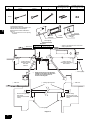
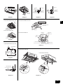
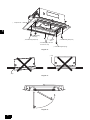
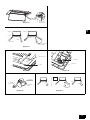
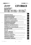
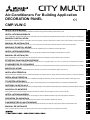
Air-Conditioners For Building Application
DECORATION PANEL
Voor een veilig en correct gebruik dient u voordat u het sierpaneel installeert deze handleiding nauwkeurig door te nemen.
MANUAL DE INSTALAÇÃO
Para uma utilização correcta e segura, leia atentamente este Manual de instalação, antes de instalar o painel decorativo.
ΕΓΧΕΙΡΙΔΙΟ ΟΔΗΓιΩΝ ΕΓΚΑΤΑΣΤΑΣΗΣ
Για ασφαλή και σωστή χρήση, παρακαλούμε διαβάστε προσεχτικά αυτό το εγχειρίδιο οδηγιών πριν από την τοποθέτηση του διακοσμητικού πλαισίου.
РУКОВОДСТВО ПО УСТАНОВКЕ
Для обеспечения безопасности и правильной эксплуатации перед установкой декоративной панели прочитайте данное руководство по установке.
MONTAJ ELKiTABI
Emniyetli ve doğru kullanım için dekoratif paneli monte etmeden önce lütfen bu montaj elkitabını baştan sona okuyun.
INSTALAČNÍ PŘÍRUČKA
Před namontováním ozdobného panelu si důkladně prostudujte tuto instalační příručku, abyste zařízení používali bezpečným a správným způsobem.
INŠTALAČNÁ PRÍRUČKA
V záujme bezpečného a správneho používania si dôkladne prečítajte túto inštalačnú príručku skôr, ako začnete inštalovať dekoračný panel.
TELEPÍTÉSI KÉZIKÖNYV
A biztonságos és helyes használat érdekében, kérjük, olvassa el figyelmesen ezt a telepítési kézikönyvet a dekorpanel telepítése előtt.
INSTRUKCJA INSTALACJI
Przed przystąpieniem do instalacji należy zapoznać się z instrukcją instalacji, w której opisano zasady bezpiecznego i prawidłowego użytkowania panelu ozdobnego.
NAVODILA ZA MONTAŽO
Pred montažo okrasne plošče temeljito preberite ta navodila za montažo, da boste zagotovili varno in pravilno uporabo.
INSTALLATIONSHANDBOK
För att få en säker och korrekt användning bör man läsa igenom denna installationshandbok noga innan dekorpanelen installeras.
PRIRUČNIK ZA UGRADNJU
D
F
E
I
РЪКОВОДСТВО ЗА ИНСТАЛИРАНЕ
BG
MANUAL DE INSTALARE
RO
Radi sigurne i pravilne uporabe, prije ugradnje dekorativne ploče, molimo temeljito pročitajte ovaj priručnik.
NL
INSTALLATIEHANDLEIDING
P
Per un uso corretto e sicuro, leggere il presente manuale di installazione prima di installare il pannello decorativo.
GR
MANUALE DI INSTALLAZIONE
RU
Para conseguir un uso correcto y seguro, por favor, lea con atención este manual de instalación antes de montar el panel decorativo.
TR
MANUAL DE INSTALACIÓN
CZ
Afin d’éviter tout accident et d’assurer une utilisation correcte de l’appareil, veuillez lire attentivement le présent manuel avant d’installer le panneau de finition.
SV
MANUEL D’INSTALLATION
HG
Um zu gewährleisten, dass das Gerät korrekt und sicher betrieben wird, lesen Sie bitte dieses Installationshandbuch gründlich vor der Anbringung der Zierplatte durch.
PO
INSTALLATIONSHANDBUCH
SL
For safe and correct use, please read this installation manual thoroughly before installing the decoration panel.
HR SW
INSTALLATION MANUAL
GB
CMP-VLW-C
За безопасна и правилна употреба, моля, прочетете докрай настоящето ръководство преди да монтирате декоративния панел.
Pentru o utilizare sigură şi corectă, vă rugăm să citiţi acest manual în întregime înainte de a instala panoul decorativ.
A Name
D Panel Mounting Bolt
B Qty
2(long)
E Tie Anchor
2(short)
2
F Truss Bolt (Only in the
case of model 100, 125)
2
G Washer (Only in the
case of model 100, 125)
2
C Shape
GB
<Accessories Positions>
The decorative panel described in this
manual has the enclosed parts
attached to the location indicated in
Figure 1.
*The accessories are stuck to the packing
cardboard.
L Accessories
I Top of the
cardboard
J Panel
K Bottom of the
cardboard
H Panel gauge
Diagram 1
A
CMP-VLW-C
57 mm - 67 mm
D Check to see that the main unit is level
using a spirit level.
#
A Spirit level
Model
B Ceiling opening
dimension in the
short side
direction
E Ceiling opening
dimension in the long
side direction
F Panel gauge
G Install panel gauge in the direction
suitable for the short side direction
and the long side direction as
shown in the diagram.
I Set the ceiling opening
ends to this
range.(Recommended
OO
10mm)
I Set the ceiling
opening ends to this
range.(Recommended
OO
10mm)
F Panel gauge
Diagram 2
2
C Main unit
OO
H Ceiling opening ends
OO
C Main unit
3
How to move the
service panel
1
B Main unit
A First stage
bolt
A Service panel
D Main unit
A Ceiling
B Ceiling
2
C Second stage bolt
C Panel Mounting
Bolt (long)
E Panel Mounting
Bolt (long)
Panel Mounting
Bolt (long)
Diagram 4
In the case of model 40, 63, 100
Diagram 5
Diagram 6
In the case of model 40, 63, 100
A Side
frame
GB
Diagram 3
D Panel
Enlarged diagram of section A
#
B Lead wire (from panel)
for vane motor
B Control box
cover
A Drain pan
In the case of model 125
In the case of model 125
C Maintenance
cover
D Main unit
control box
E Cable
ties
٨
B Control box
cover
٨
Diagram 7
٨
٨
٨
٨
F Panel-side connector (white)
G Vane
motor
H Panel-side connector
(green)
In the case of model 40, 63, 100
Diagram 8
A Indoor substrate
In the case of model 100
B
Lead wire (from panel)
for vane motor
In the case of model 125
CN7V
C Ivory
Diagram 9
A Panel Mounting Bolt
C
Main unit
B Ceiling
A Washer
A Washer
D Decorative Panel
Diagram 10
B Truss Bolt
B Truss Bolt
Diagram 11
3
GB
D U shaped notch
B Panel Mounting
Bolt (long)
C Panel Mounting Bolt (short)
D U shaped
notch
C Panel Mounting Bolt (short)
A Truss Bolt (Only in the case
of model 100, 125)
B Panel Mounting Bolt (long)
Diagram 12
A Gap
A Gap
Diagram 13
3
2
1
4
Diagram 14
Diagram 15
A Wire hook slot
(on both panels)
Pattern 1
GB
Only in the case of model 40, 63, 100
Pattern 2
A Fixed
A Fixed
A Fixed
B *Vane is fixed.
C Airflow can be set using
remote controller.
Diagram 16
A Vane motor cover
B Connector
A Vane motor
B Catch
Diagram 18
Diagram 17
Example
B Vane motor
A Fixed
A Fixed
㧟
㧟
A Connector
A Fixed
C Lock release
button
㧟
㧣
㧣
㧣
Diagram 19
Diagram 20
5
Safety Precautions
• Read these Safety Precautions and perform installation work accordingly.
• The following two symbols include important notes concerning safety, so be
sure to read and follow them.
Warning:
This symbol denotes what could lead to serious injury or death if you
misuse the CMP-P·LW-D / CMP-P·LX-D / CMP-VLW-B.
Caution:
This symbol denotes what could lead to a personal injury or damage to
your property if you misuse the CMP-P·LW-D / CMP-P·LX-D / CMP-VLW-B.
• After reading this installation manual, give it and the instruction manual to the
end user.
• The end user should keep this manual and the indoor unit installation manual
in a place where he or she can see it at anytime. When someone moves or
repairs the CMP-P·LW-D / CMP-P·LX-D / CMP-VLW-B, make sure that this
manual is forwarded to the end user.
Prior to Trial Operation
Caution:
• Do not touch switches with wet hands.
- Doing so may cause an electric shock.
• Do not run the system with the air filter removed.
- Doing so may cause the system to fail due to internal dirt blockages.
• Do not run the system with the panel and/or guard removed.
- Doing so may cause burn and/or electric shock injury due to contact with or
enmeshing in the machine, moving parts, high-temperature units and/or
highvoltage units.
• Do not turn OFF the power immediately after halting operation.
- Always wait at least five or more minutes before turning OFF the power to
prevent leaks and system failure.
1. Model Names and Usable Types
Model Names
GB
Warning:
• Ask your dealer or technical representative to install the unit.
- Any deficiency caused by your own installation may result in an electric
shock or fire.
• Firmly connect the wiring using the specified cables. Carefully check
that the cables do not exert any force on the terminals.
- Improper wiring connections may produce heat and possibly a fire.
• Be sure to select Mitsubishi-designated products when purchasing
separately retailed products such as a humidifier.
- Also, be sure to request the services of a specialist technician for
installation work, as installation by an untrained person (user, etc.) may
result in deficiencies such as leaks, electric shock or fire.
• Ensure that installation work is performed correctly in adherence to this
installation manual.
- Any deficiency caused by installation may result in leaks, electric shock or
fire.
• All electrical work must be performed by a licensed technician in
accordance to technical standards related to electrical facilities,
extension bylaws and the instructions given in this manual. And always
use a dedicated power supply.
- Insufficient electrical circuit capacity and/or installation deficiencies may
cause electric shock or fire.
• Never alter the installation setup. Talk to your retailer if repairs are
required.
- Repair deficiencies may cause leaks, electric shock or fire.
Prior to installation
Caution:
• Do not use this system for special applications such as the storage of
food, flora & fauna, precision instruments and works of art.
- Doing so may cause the quality of the item concerned to deteriorate.
• When installing this system in a hospital or communication facility, take
ample countermeasures against noise.
- Inverters, household generators and high-frequency communication
equipment may cause the air conditioner to malfunction or fail. Moreover,
the air conditioner may effect medical equipment or communication
equipment preventing patient therapy or interfering with image
transmissions or causing noise.
• Do not use in any special environment.
- Using in any place exposed to oil, steam and sulfuric gas may deteriorate
the performance significantly or give damage to the component parts.
• Do not install unit above items that if leaked upon would cause
problems.
- Moisture drips from the indoor unit if humidity exceeds 80% or the drain
outlet becomes blocked. Also, when the unit is used as a heater, the
outdoor unit's drain will drip, so, if necessary, also provide a confluent drain
for the outdoor unit.
Prior to Installation (Various Units) and Electrical Wiring
Caution:
• Wire the units so that there is no tension on the electrical wiring.
- Tension may cause wire breakage, heating or fire.
• Be sure to comprehensively dispose of packing material.
• Be sure to take ample precautions for transportation of the product.
- Products weighing 20 kg or more should not be transported by one person.
- Some products come packaged with polypropylene bands. Do not use such
bands when transporting the product, as doing so may cause accidents.
- The front side of the heat exchanger fan may cause cuts if touched with a
bare hand, so wear gloves and take care when handling.
- Plastic bags must be kept away from children. Also be sure to tear them
before throwing away to further reduce the risk of suffocation accidents.
6
CMP-40VLW-C
CMP-63VLW-C
CMP-100VLW-C
CMP-125VLW-C
Usable Types
PLFY-P06NLMU-E
PLFY-P20VLMD-E
PLFY-P08NLMU-E
PLFY-P25VLMD-E
PLFY-P12NLMU-E
PLFY-P30VLMD-E
PLFY-P15NLMU-E
PLFY-P40VLMD-E
PLFY-P50VLMD-E
PLFY-P63VLMD-E
PLFY-P18NLMU-E
PLFY-P80VLMD-E
PLFY-P100VLMD-E
PLFY-P125VLMD-E
2. Checking Supplied Parts
Check that the parts shown in Diagram 1 are provided for this decorative panel.
(Note that truss bolts and washers are provided only for model 100 and 125.)
[Diagram 1] (P.2)
A
Name
B
Qty
C
Shape
D
Panel Mounting Bolt
E
Tie Anchor
F
Truss Bolt (Only in the case of model 100, 125)
G
Washer (Only in the case of model 100, 125)
<Accessories Positions>
H
Panel gauge
I
Top of the cardboard
J
Panel
K
Bottom of the cardboard
L
Accessories
* The accessories are stuck to the packing cardbord.
3. Preparation Prior to Installation of
Decorative Panel
Check to see that the unit body has been suspended correctly prior to
installation of the decorative panel. For the unit body to be correctly installed, its
bottom surface must be raised above the ceiling surface at a height between
57 mm and 67 mm (see Diagram 2). Use the panel gauge at the top of the
cardboard box to adjust and check the main unit's installation position from the
short and long sides of the rectangular opening as shown in the following figure.
[Diagram 2] (P.2)
A
Spirit level
B
Ceiling opening dimension in the short side direction
C
Main unit
D
Check to see that the main unit is level using a spirit level.
E
Ceiling opening dimension in the long side direction
F
Panel gauge
G
Install panel gauges in the directions suitable for the short side direction and the
long side direction as shown in the diagram.
H
Ceiling opening ends
I
Set the ceiling opening ends to this range. (Recomended 10 mm)
• Insufficient air flow, moisture dripping and panel warping may occur if the
unitbody is incorrectly aligned with the ceiling surface.
(The panel gauge is designed to show the standard installation positions.)
• Check to see that the ceiling opening has the following dimensions.
Model 40 dimensions: 1040 × 670
Model 63 dimensions: 1210 × 670
Model 100 dimensions: 1710 × 670
Model 125 dimensions: 1970 × 670
• Move the service panel in the order shown in Diagram 3 to remove it.
(Cushioning material is sandwiched between the panel frame and the panel.
Take out this cushioning and then remove the panel.)
* See Diagram 14 for details concerning service panel installation.
[Diagram 3] (P.3)
<How to move the service panel>
A
Service panel
Temporarily tighten the two panel mounting screws (long, supplied) diagonally
from each other as shown in Diagram 4 prior to installing the decorative panel.
(Screw in the long panel mounting screws until their first thread has gone
through the nut on the unit as shown in Diagram 5.) Finally, check that the auto
vane connector is definitely set in the direction of the piping before commencing
installation.
[Diagram 5] (P.3)
A
First stage bolt
B
Ceiling
C
Second stage bolt
D
Main unit
E
Panel Mounting Bolt (long)
Once units are directionally aligned, fit the notched holes of the panel body's
intake port over the long panel mounting bolts. (See Diagram 6.) First fit the two
holes at the side opposite the piping followed by the two holes at the piping side.
(See Diagram 12.) (Inwardly push the panel mounting bolts at the piping side to
make work easier.) Note that the panel body can be temporarily secured in this
state but may become dislodged if the panel is raised or strongly shaken. Use
the two short mounting screws to hold the other two corners.
[Diagram 6] (P.3)
A
Ceiling
B
Main unit
C
Panel Mounting Bolt (long)
D
Panel
• Auto Vane Wiring
In the case of Model 40, 63, 100
Remove the main unit control box. (See Diagram 7.)
[Diagram 7] (P.3)
A
Side frame
B
Control box cover
Next, pass the vane motor lead wire through the side frame hole and the channel
on the narrow side of the drain pan. (See Diagram 8.)
A
Drain pan
B
Lead wire (from panel) for vane motor
C
Maintenance cover
D
Main unit control box
E
Cable ties
F
Panel-side connector (white)
G
Vane motor
H
Panel-side connector (green)
Firmly insert the panel's vane motor lead wire connector into CN7V of the indoor
substrate in the main unit control box. (See Diagram 9.)
Indoor substrate
Ivory
B
Lead wire (from panel) for vane motor
In the case of Model 125
When removing the connector cover (screwed at two places) as shown in
Diagram 7, the electrical box is exposed. Find the vane motor connector.
Connect the two connectors (for vane motor drive and limit switch) leading from
the panel to each connector supplied with the electrical box. (See Diagram 8.)
* Gather the lead wire into the tie anchor provided to prevent it from becoming
trapped in the service panel.
* Never force the auto vane when handling, as doing so may cause system
failure.
• Securing the Decorative Panel
Raise the decorative panel into position and tighten the second stage panel
mounting bolts (long) until the panel touches the ceiling surface. (See Diagram
10.) Also, only in the case of the model 100, 125, the truss bolts and washers
provided should be used to secure the panel against the central section of the
main unit. (See Diagram 11.)
[Diagram 10] (P.3)
A
Panel Mounting Bolt
B
Ceiling
C
Main unit
D
Decorative Panel
B
Truss Bolt
[Diagram 11] (P.3)
A
Washer
Gap
5. Service Panel Installation
• Service Panel Installation
Slot in one side of the service panel and then move it in the order shown in
Diagram 14 to install.
[Diagram 14] (P.4)
* Be sure to slot the anti-fall wires into the holes on both sides of the panel to
prevent accidents. (See Diagram 15.)
[Diagram 15] (P.5)
A
Wire hook slot (on both panels)
6. Checking Auto Vane Movement
Implement the contents in either the main unit installation manual (Trial
Operation) or the instruction manual to check the movement of the auto vane.
7. Method for Dividing Air Output
(Only in the case of model 40, 63, 100)
• The left and right auto vanes can be individually set to divide the air output.
(See Diagram 16.)
[Diagram 16] (P.5)
<Pattern 1>
A
Fixed
B
* Vane is fixed.
C
Airflow can be set using remote
controller.
<Pattern 2>
Fixed
• Vane Securing Method
- Remove the vane motor cover of the vane to be secured.
The catches holding the cover may break if the cover is forcefully removed.
Press the catches with a minus screwdriver to aid easy removal. (See
Diagram 17.)
[Diagram 17] (P.5)
A
[Diagram 9] (P.3)
C
A
* Recheck the suspension status of the main unit if installation of the panel is
not successful.
A
[Diagram 8] (P.3)
A
[Diagram 13] (P.4)
Vane motor cover
B
Catch
- Remove the connector connected to the vane. The connector is locked, so
be sure to hold down the lock release button when removing the connector.
(See Diagrams 18 and 19.)
[Diagram 18] (P.5)
A
Vane motor
B
Connector
B
Vane motor
[Diagram 19] (P.5)
A
Connector
C
Lock release button
- Remount the vane motor cover in reverse order to the removal.
- Slowly align the vane in the desired setting direction.
8. Air Flow Distribution (7:3) Method
• An air deflector (sold separately) can be used to distribute the supply air on
the left and right in the proportion of 7 to 3.
* Only in the case of the panel model 40,63, 100 The airflow types shown in
Diagram 20 can be selected if the distributor is combined with the air
output divider described in item 7.
[Diagram 20] (P.5)
<example>
A
Fixed
• Panel Bolt Tightening Order
1. Alternately and evenly tighten the two truss bolts on the middle section of the
panel (only in the case of model 100,125).
2. Once item 1. has been completed, tighten the long and short mounting bolts
temporarily tightened in Diagrams 5 and 6 and the truss bolts. (See Diagram
12.)
[Diagram 12] (P.4)
A
Truss Bolt (Only in the case of model 100, 125)
B
Panel Munting Bolt (long)
C
Panel Munting Bolt (short)
D
U shaped notch
NOTE:
The panel may warp if the tightening order is not adhered to or temporary
tightening was not performed.
* Evenly tighten the four bolts (six bolts the panel for model 100,125) so that
there are no gaps between the unit body and decorative panel and between
the decorative panel and ceiling surface.
* If there are gaps between the unit body and decorative panel, air flow will be
insufficient, which may cause condensation and moisture dripping. Also, if
there are gaps between the decorative panel and ceiling surface, panel
condensation and ceiling smudging may occur. (See Diagram 13.)
7
GB
4. Decorative Panel Installation
This product is designed and intended for use in the residential,
commercial and light-industrial environment.
The product at hand is
based on the following
EU regulations:
• Low Voltage Directive 2006/95/EC
• Electromagnetic Compatibility Directive
2004/108/EC
Please be sure to put the contact address/telephone number on
this manual before handing it to the customer.
HEAD OFFICE: TOKYO BLDG. , 2-7-3, MARUNOUCHI, CHIYODA-KU, TOKYO 100-8310, JAPAN
Authorized representative in EU: MITSUBISHI ELECTRIC EUROPE B.V.
HARMAN HOUSE, 1 GEORGE STREET, UXBRIDGE, MIDDLESEX UB8 1QQ, U.K.
WT05553X01