1
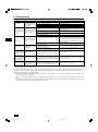
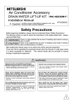
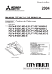
Air-Conditioners INDOOR UNIT OPERATION MANUAL For safe and correct use, please read this operation manual thoroughly before operating the air-conditioner unit. D GB PEFY-P-VML-E PEFY-P-VMS-E PDFY-P-VM-E PEFY-P-VMM-E PEFY-P-VMR-E-L/R PFFY-P-VLRM(M)-E PEFY-P-VMH-E PLFY-P-VLMD-E PFFY-P-VLEM-E Zum sicheren und einwandfreien Gebrauch der Klimaanlage dieses Bedienungshandbuch vor Inbetriebnahme gründlich durchlesen. F BEDIENUNGSHANDBUCH MANUAL DE INSTRUCCIONES Lea este manual de instrucciones hasta el final antes de poner en marcha la unidad de aire acondicionado para garantizar un uso seguro y correcto. I Pour une utilisation correcte sans risques, veuillez lire le manuel d’utilisation en entier avant de vous servir du climatiseur. E MANUEL D’UTILISATION Leggere attentamente questi istruzioni di funzionamento prima di avviare l’unità, per un uso corretto e sicuro della stessa. BEDIENINGSHANDLEIDING NL ISTRUZIONI DI FUNZIONAMENTO Voor een veilig en juist gebruik moet u deze bedieningshandleiding grondig doorlezen voordat u de airconditioner gebruikt. PI MANUAL DE OPERAÇÃO E°XEIPI¢IO O¢H°IøN XPH™Eø™ °È· ·ÛÊ¿ÏÂÈ· Î·È ÛˆÛÙ‹ ¯Ú‹ÛË, ·Ú·Î·Ï›ÛÙ ‰È·‚¿ÛÂÙ ÚÔÛ¯ÙÈο ·˘Ùfi ÙÔ ÂÁ¯ÂÈÚ›‰ÈÔ ¯Ú‹Ûˆ˜ ÚÈÓ ı¤ÛÂÙ Û ÏÂÈÙÔ˘ÚÁ›· ÙË ÌÔÓ¿‰· ÎÏÈÌ·ÙÈÛÌÔ‡. RU РУКОВОДСТВО ПО ЭКСПЛУАТАЦИИ GR Para segurança e utilização correctas, leia atentamente o manual de operação antes de pôr a funcionar a unidade de ar condicionado. TR Для обеспечения правильного и безопасного использования следует ознакомиться с инструкциями, указанными в данном руководстве по эксплуатации, тщательным образом до того, как приступать к использованию кондиционера. IfiLETME ELK‹TABI SL PO HG SV CZ Emniyetli ve do¤ru biçimde nas›l kullan›laca¤›n› ö¤renmek için lütfen klima cihaz›n› iflletmeden önce bu elkitab›n› dikkatle okuyunuz. WT04883X02_h1_h4.p65 3 07.8.21, 9:10 AM E I NL Remote controller-Button Fernbedienungs-Taste Touche Commande à distance GB D F P Controlador remoto-Botón Bottone dell’unità del comando a distanza Knop afstandbediening Botão do controlo remoto 1 Botón [Ajuste de la temperatura] 2 Botón [TIMER MENU] 3 Botón [Modo] 5 Botón [Rejilla] Botón [MONITOR/SET] 4 Botón [TIMER ON/OFF] Botón [BACK] Botón [SET DAY] 1 TEMP. 3 BACK ON/OFF MONITOR/SET B 7 A 0 CHECK TEST CLOCK D 1 [Set Temperature] Button 2 [TIMER MENU] Button FILTER DAY OPERATION 4 3 [MONITOR/SET] Button 4 5 [SET DAY] Button [Fan Speed] Button 8 [Ventilation] Button 9 8 Botón [Ventilación] Botón [Control de los deflectores] C [Mode] Button Botón [CHECK/CLEAR] 0 Botón [TEST RUN] A Botón [FILTER] B Botón [ON/OFF] Botón [ ] C Posición del sensor de temperatura ambiente incorporado D Botón [Ajuste de la hora] • Nunca exponga el mando a distancia a la luz directa del sol. Si lo hace, se producirá una lectura errónea de la temperatura de la habitación. • Nunca ponga ningún obstáculo alrededor de la sección inferior derecha del mando a distancia. Si lo hace, se producirá una lectura errónea de la temperatura de la habitación. 1 Pulsante [Impostazione temperatura] 2 Pulsante [TIMER MENU] [Louver] Button [Vane Control] Button 3 Pulsante [Modalità] 5 Pulsante [Deflettore] Pulsante [MONITOR/SET] 4 [OPERATION] Button 7 7 9 [BACK] Button [TIMER ON/OFF] Button 6 CLEAR 568 Botón [Velocidad de ventilador] Botón [OPERATION] ON/OFF 2 MENU Botón [OPERATION] 6 Pulsante [TIMER ON/OFF] Pulsante [BACK] Pulsante [SET DAY] 6 Pulsante [Velocità di ventilazione] 8 Pulsante [Ventilazione] [OPERATION] Button Pulsante [OPERATION] 7 Pulsante [Comando lamelle] Pulsante [OPERATION] 9 [CHECK/CLEAR] Button 0 [TEST RUN] Button 9 Pulsante [CHECK/CLEAR] 0 Pulsante [TEST RUN] A [FILTER] Button B [ON/OFF] Button A Pulsante [FILTER] B Pulsante [ON/OFF] Pulsante [ ] [ ] Button C Posizione del sensore temperatura ambiente incorporato D Pulsante [Imposta ora] • Never place any obstacle around the lower right-hand section of the remote controller. Doing so can result in the erroneous measurement of room temperature. Non esporre mai il comando a distanza alla luce diretta del sole, in quanto questo può alterare la corretta rilevazione della temperatura ambiente. • Non porre alcun ostacolo attorno alla sezione inferiore destra del comando a distanza, in quanto questo può alterare la corretta rilevazione della temperatura ambiente. 1 [Temperatureinstellung]-Taste 1 [Temperatuur instellen]-knop 2 [TIMER MENU]-Taste 2 [TIMER MENU]-knop C Position of built-in room temperature sensor • Never expose the remote controller to direct sunlight. Doing so can result in the erroneous measurement of room temperature. • 3 [MONITOR/SET]-Taste 4 5 [SET DAY]-Taste [Gebläsegeschwindigkeit]-Taste 8 [Lüftung]-Taste [Set Time] Button [Modus]-Taste [BACK]-Taste [TIMER ON/OFF]-Taste 6 D [Luftklappe]-Taste 4 [OPERATION]-Taste 7 [Richtungsklappensteuerung]-Taste 3 [MONITOR/SET]-knop [TIMER ON/OFF]-knop 5 [SET DAY]-knop [Jaloezie]-knop [OPERATION]-knop 6 [Ventilatorsnelheid]-knop 8 [Ventilatie]-knop [OPERATION]-Taste [Modus]-knop [BACK]-knop 7 [Ventilatorblad regelen]-knop [OPERATION]-knop 9 [CHECK/CLEAR]-Taste 0 [TEST RUN]-Taste 9 [CHECK/CLEAR]-knop 0 [TEST RUN]-knop A [FILTER]-Taste B [ON/OFF]-Taste A [FILTER]-knop B [ON/OFF]-knop [ ]-Taste [ ]-knop C Position des eingebauten Raumtemperatursensors C Positie van ingebouwde kamertemperatuursensor D Zeiteinstell-Tasten D [Tijd instellen]-knop • Die Fernbedienung nicht direkter Sonneneinstrahlung aussetzen. Die Raumtemperatur wird sonst nicht korrekt gemessen. • Laat de afstandsbediening nooit in direct zonlicht liggen. Als u dit toch doet kan het zijn dat de kamertemperatuur onjuist gemeten wordt. • Den rechten unteren Teil der Fernbedienung nicht blockieren. Die Raumtemperatur wird sonst nicht korrekt gemessen. • Zet of hang nooit iets in de buurt van het gedeelte rechtsonder op de afstandsbediening. Als u dit toch doet kan het zijn dat de kamertemperatuur onjuist gemeten wordt. 1 Touche [Réglage de la température] 1 Botão [Ajustar Temperatura] 2 Touche [TIMER MENU] 2 Botão [TIMER MENU] 3 Touche [MONITOR/SET] 4 Touche [BACK] 5 Touche [TIMER ON/OFF] Touche [SET DAY] 6 Touche [Vitesse du ventilateur] 8 Touche [Ventilation] Touche [Mode] Touche [Louvre] 4 Touche [OPERATION] 7 Touche [Commande des ailettes] 3 Botão [Modo] 5 Botão [Aleta] Botão [MONITOR/SET] Botão [TIMER ON/OFF] Botão [BACK] Botão [SET DAY] Botão [OPERATION] 6 Botão [Velocidade do Ventilador] 8 Botão [Ventilação] Touche [OPERATION] 7 Botão [Controlo de Defletores] Botão [OPERATION] 9 Touche [CHECK/CLEAR] 0 Touche [TEST RUN] 9 Botão [CHECK/CLEAR] 0 Botão [TEST RUN] A Touche [FILTER] B Touche [ON/OFF] A Botão [FILTER] B Botão [ON/OFF] Touche [ ] Botão [ ] C Position du capteur de température de la pièce intégré C Posição do sensor da temperatura ambiente incorporado D Touche de [réglage de l’heure] D Botão [Ajustar Tempo] • Ne jamais laisser la commande à distance en plein soleil sinon les données de température ambiante risquent d’être erronées. • Nunca exponha o controlo remoto à luz directa do sol, porque pode dar-lhe valores de temperatura da peça anormais. • Ne jamais placer d’obstacle devant la partie inférieure droite de la commande à distance sinon la lecture des températures ne sera pas correcte. • Nunca coloque nenhum obstáculo em volta da secção inferior direita do controlo remoto, pois isso pode dar-lhe valores de temperatura da peça anormais. 2 WT04883X02_p02.p65 2 07.9.13, 1:10 PM GB D F E I NL Remote controller-Display Fernbedienung-Anzeige Affichage Commande à distance P O A Controlador remoto-Indicador Display dell’unità del comando a distanza Display afstandbediening Visualização do controlo remoto A Hora actual/hora del temporizador B Indicador de control centralizado C Indicador de desconexión del temporizador D Indicador de modo del temporizador E Pantalla de modo de funcionamiento: FRÍO, DESHUMIDIFICACION, AUTOMÁTICO, VENTILACIÓN, CALOR TIME SUN MON TUE WED THU FRI SAT Hr ON TIMER AFTER AFTER OFF ERROR CODE FUNCTION FILTER WEEKLY SIMPLE AUTO OFF ˚F ˚C B ˚F ˚C C TEMP. ONLY 1Hr. G N L F Indicador de modo de función G F K H Indicador de encendido I Rejilla J Ventilación K Señalización de filtro ON/OFF IM H P J Temperatura prefijada L Posición de sensor M Temperatura de la habitación N Ajuste de deflectores O Velocidad del ventilador P Lámpara de funcionamiento D GB E Current time/Timer time A Ora corrente/Timer B Centralized control indicator B Indicatore comando centralizzato C Timer OFF indicator C Indicatore Timer non attivato D Timer mode indicator D Indicatore modalità Timer E Operation mode display: E Visualizzazione modalità di funzionamento: F Function mode indicator G Preset temperature H Power indicator I Louver F Indicatore modalità funzione G Preimpostazione temperatura J Ventilation K Filter sign H Indicatore alimentazione I Deflettore L Sensor position M Room temperature J Ventilazione K Simbolo del filtro N Vane setting O Fan speed L Posizione del sensore M Temperatura ambiente P Operation lamp N Impostazione lamelle O Velocità di ventilazione P Spia di funzionamento FAN, HEAT COOL, DRY, AUTO, VENTILAZIONE, HEAT F AUTO, E DRY, I COOL, D A Aktuelle Uhrzeit/Timer-Zeit A Huidige tijd/Timertijd B Anzeige für Zentralsteuerung B Indicatielampje voor centraal regelen C Timer-OFF-Anzeige C Indicatielampje timer UIT D Anzeige des Timer-Modus D Indicatielampje timermodus E Betriebsartenanzeige: E Werkingsstand: F Anzeige des Funktionsmodus G Voreingestellte Temperatur F Indicatielampje functiemodus G Vooraf ingestelde temperatuur H Netzanzeige I Luftklappe H Voedingsindicatielampje I Jaloezie J Ventilation K Filtersymbol J Ventilatie K Filterteken L Sensorposition M Raumtemperatur L Plaats van sensor M Kamertemperatuur N Flügeleinstellung O Ventilatorgeschwindigkeit N Instelling ventilatorblad O Ventilatorsnelheid P Betriebsanzeige P Bedrijfslamp A Heure réelle/heure de la minuterie A Hora actual/Hora do temporizador B Témoin de commande à distance centralisée B Indicador de controlo centralizado C Témoin de minuterie OFF C Indicador de temporizador OFF D Témoin de mode de minuterie D Indicador de modo do temporizador E Affichage du mode de fonctionnement: E Visor do modo de funcionamento: CHAUD F Indicador do modo de funcionamento G Temperatura predefinida AUTO, Lüfter, Heizen COOL, DRY, AUTO, FAN, HEAT P Trocknen, DESHU, AUTO, VENTILATION, COOL, DRY, AUTO, FAN, F Témoin de mode de fonctionnement G Température prédéfinie H Indicador de corrente I Aba H Témoin d’alimentation I Louvre J Ventilação K Sinal do filtro J Ventilation K Signe du filtre L Posição do sensor M Temperatura ambiente L Position du capteur M Température de la pièce N Regulação da palheta O Velocidade da ventoinha N Réglage des ailettes O Vitesse du ventilateur P Lâmpada de funcionamento P Témoin de fonctionnement HEAT 5 WT04883X02_front.p65 5 07.8.20, 6:56 PM TR FROID, RU GR Kühlen, NL A [Fig. A] <PLFY-P20~100VLMD-E> A <PLFY-P125VLMD-E> A <PDFY-P-VM-E> <PEFY-P-VML-E> A <PEFY-P-VMM-E> A A 1 2 1: In case of rear inlet Bei Einlass von hinten En cas d’entrée arrière En el caso de unidad interior trasera In caso di ingresso dell'aria dalla parte posteriore Bij een achterinlaat No caso de unidade interior traseira ™Â ÂÚ›ÙˆÛË ›Ûˆ ÂÈÛ·ÁˆÁ‹˜ При воздухозаборнике сзади Arka girifl durumunda 2: In case of bottom inlet Bei Einlass von unten En cas d’entrée sur le dessous En el caso de unidad interior inferior In caso di ingresso dell'aria dalla parte inferiore Bij een onderinlaat No caso de unidade interior inferior ™Â ÂÚ›ÙˆÛË Î¿Ùˆ ÂÈÛ·ÁˆÁ‹˜ При воздухозаборнике внизу Alt girifl durumunda A: Filter Filter Filtre Filtro Filtro Filter Filtro º›ÏÙÚÔ Фильтр Filtre 8 WT04883X02_illust.p65 8 07.8.21, 9:58 AM : Air Flow Luftstrom Flux d’air Flujo de aire Flusso d’aria Luchtstroom Fluxo de Ar ƒÔ‹ ·¤Ú· Воздушный поток Hava Ak›m› [Fig. A] <PEFY-P-VMH-E> <PFFY-P-VLEM-E, VLRM(M)-E> A A <PEFY-P-VMS-E> A <PEFY-P-VMR-E-L/R> A A 1 2 1: In case of rear inlet Bei Einlass von hinten En cas d’entrée arrière En el caso de unidad interior trasera In caso di ingresso dell'aria dalla parte posteriore Bij een achterinlaat No caso de unidade interior traseira ™Â ÂÚ›ÙˆÛË ›Ûˆ ÂÈÛ·ÁˆÁ‹˜ При воздухозаборнике сзади Arka girifl durumunda 2: In case of bottom inlet Bei Einlass von unten En cas d’entrée sur le dessous En el caso de unidad interior inferior In caso di ingresso dell'aria dalla parte inferiore Bij een onderinlaat No caso de unidade interior inferior ™Â ÂÚ›ÙˆÛË Î¿Ùˆ ÂÈÛ·ÁˆÁ‹˜ При воздухозаборнике внизу Alt girifl durumunda A: Filter Filter Filtre Filtro Filtro Filter Filtro º›ÏÙÚÔ Фильтр Filtre : Air Flow Luftstrom Flux d’air Flujo de aire Flusso d’aria Luchtstroom Fluxo de Ar ƒÔ‹ ·¤Ú· Воздушный поток Hava Ak›m› 9 WT04883X02_illust.p65 9 07.8.27, 4:18 PM Contents 1. Safety precautions .................................................................................... 1.1. Installation ............................................................................... 1.2. During operation ...................................................................... 1.3. Disposing of the unit ................................................................ 2. Names and functions of various parts ...................................................... 3. How to operate ......................................................................................... 3.1. ON/OFF ................................................................................... 3.2. Selecting operation .................................................................. 3.3. Room temperature adjustment ................................................ 10 10 10 11 11 11 11 11 12 4. 5. 6. 7. 8. 3.4. Fan speed adjustment ............................................................. 3.5. Adjustment of up/down airflow direction .................................. 3.6. Ventilation ................................................................................ 3.7. Others ...................................................................................... The smart way to use ............................................................................... Caring for the machine ............................................................................. Troubleshooting ......................................................................................... Installation, transferring works, and checking ........................................... Specifications ............................................................................................ 12 12 13 13 13 13 14 15 15 1. Safety precautions GB s Before operating the unit, make sure you read all the “Safety precautions”. s “Safety precautions” lists important points about safety. Please be sure to follow them. Caution: The outdoor unit should be installed in a location where air and noise emitted by the unit will not disturb the neighbours. 2) Indoor unit Symbols used in the text Warning: D Describes precautions that should be observed to avoid the risk of injury or death to the user. Warning: The indoor unit should be securely installed. If the unit is loosely mounted, it may fall, causing injury. 3) Remote controller Caution: Warning: Describes precautions that should be observed to prevent damage to the unit. F Symbols used in the illustrations : Indicates an action that must be avoided. : Indicates that important instructions must be followed. E : Indicates a part which must be grounded. : Indicates that caution should be taken with rotating parts. (This symbol is displayed on the main unit label.) <Color: yellow> : Beware of electric shock. (This symbol is displayed on the main unit label.) I <Color: yellow> 4) Drain hose Caution: Make sure that the drain hose is installed so that drainage can go ahead smoothly. Incorrect installation may result in water leakage, causing damage to furniture. 5) Power line, fuse or circuit breaker Warning: Warning: NL The remote controller should be installed in such a way that children cannot play with it. Carefully read the labels affixed to the main unit. • • • 1.1. Installation s After you have read this manual, keep it and the Installation Manual in a RU GR P safe place for easy reference whenever a question arises. If the unit is going to be operated by another person, make sure that this manual is given to him or her. • TR • • GB • GB • • • GB 6) Grounding Warning: • • Caution: The unit should not be installed by the user. Ask the dealer or an authorized company to install the unit. If the unit is installed improperly, water leakage, electric shock or fire may result. Use only accessories authorized by Mitsubishi Electric and ask your dealer or an authorized company to install them. If accessories are installed improperly, water leakage, electric shock or fire may result. The Installation Manual details the suggested installation method. Any structural alteration necessary for installation must comply with local building code requirements. Never repair the unit or transfer it to another site by yourself. If repair is performed improperly, water leakage, electric shock or fire may result. If you need to have the unit repaired or moved, consult your dealer. Keep the electric parts away from water (washing water) etc. It might result in electric shock, catching fire or smoke. Note1: When washing the Heat Exchanger and Drain Pan, ensure the Control Box, Motor and LEV remain dry, using a water proof covering. Note2: Never drain the washing water for the Drain Pan and the Heat Exchanger using the Drain Pump. Drain separately. The appliance is not intended for use by young children or infirm persons without supervision. Young children should be supervised to ensure that they do not play with the appliance. Do not use a leak detection additive. • • Caution: • • • • • GB GB Do not use any sharp object to push the buttons, as this may damage the remote controller. Do not twist or tug on the remote controller cord as this may damage the remote controller and cause malfunction. Never remove the upper case of the remote controller. It is dangerous to remove the upper case of the remote controller and touch the printed circuit boards inside. Doing so can result in fire and failure. Never wipe the remote controller with benzene, thinner, chemical rags, etc. Doing so can result in discoloration and failure. To remove heavy stains, soak a cloth in neutral detergent mixed with water, wring it out thoroughly, wipe the stains off, and wipe again with a dry cloth. Never block or cover the indoor or outdoor unit’s intakes or outlets. Tall items of furniture underneath the indoor unit, or bulky items such as large boxes placed close to the outdoor unit will reduce the unit’s efficiency. Warning: Warning: • The unit must be properly grounded. Never connect the grounding wire to a gas pipe, water pipe, lightning conductor or telephone grounding wire. If the unit is not grounded properly, electric shock may result. Check frequently that the ground wire from the outdoor unit is properly connected to both the unit’s ground terminal and the grounding electrode. 1.2. During operation 1) Outdoor unit • Make sure that the unit is powered by a dedicated supply. Other appliances connected to the same supply could cause an overload. Make sure that there is a main power switch. Be sure to adhere to the unit’s voltage and fuse or circuit breaker ratings. Never use a piece of wire or a fuse with a higher rating than the one specified. • The outdoor unit must be installed on a stable, level surface, in a place where there is no accumulation of snow, leaves or rubbish. Do not stand on, or place any items on the unit. You may fall down or the item may fall, causing injury. • • Do not splash water over the unit and do not touch the unit with wet hands. An electric shock may result. Do not spray combustible gas close to the unit. Fire may result. Do not place a gas heater or any other open-flame appliance where it will be exposed to the air discharged from the unit. Incomplete combustion may result. 10 WT04883X02_en.p65 10 07.8.21, 9:06 AM Warning: Caution: Do not direct the airflow at plants or caged pets. Ventilate the room frequently. If the unit is operated continuously in a closed room for a long period of time, the air will become stale. • In case of failure 1.3. Disposing of the unit 2. Names and functions of various parts Attachment and detachment of filter Caution: • [Fig. A] (P.8, P.9) • In removing the filter, precautions must be taken to protect your eyes from dust. Also, if you have to climb up on a stool to do the job, be careful not to fall. Turn off the power supply when the filter is changed. I 3. How to operate NL I 3.1. ON/OFF Start an operation ERROR CODE ˚F ˚C ONLY 1Hr. 1 TEMP. ON/OFF 2 MENU 3 BACK MONITOR/SET ON/OFF FILTER DAY CLOCK Stop an operation FUNCTION FILTER WEEKLY SIMPLE AUTO OFF ˚F ˚C 1. Press the B [ON/OFF] button again Operation lamp goes off and operation stops. B 7 CHECK TEST OPERATION 1. Press the B [ON/OFF] button P Operation lamp lights up and operation starts. P P TIME SUN MON TUE WED THU FRI SAT Hr ON TIMER AFTER AFTER OFF E • Once the Buttons have been set, pressing of the [ON/OFF] Button only can repeat the same operation thereafter. • During operation, the operation lamp above the [ON/OFF] button lights up. CLEAR Caution: 68 Even if the [ON/OFF] Button is pressed immediately after the operation is once stopped, operation is not restarted for about 3 minutes. This function protects the machine. It automatically starts operation after the lapse of approximately 3 minutes. Before starting operation 3.2. Selecting operation • When selecting operation Start running after the “PLEASE WAIT” display has disappeared. The “PLEASE WAIT” display briefly appears on the room temperature display (max. 3 minutes) when the power is turned on and after a power failure. This does not indicate any failure of the air-conditioner. 1. Press the 3 [Mode (BACK)] Button Consecutive press of the selecting operation Button switches the operation over to E “ COOL”, “ DRY”, “ FAN”, (“ AUTO”), and (“ HEAT”). For the contents of operation, check the display. The choice of indoor unit operation mode is limited by the operation status of the outdoor unit to which a given indoor unit is connected. If an outdoor unit and some of the indoor units that are connected to the outdoor units are already operating in the cooling mode, for example, only the cooling mode is available for the rest of the units in the same group. If a different mode is requested, the symbol that corresponds to the requested mode will blink, notifying the user that the mode is currently unavailable. The same is true for the dry and heating mode. This restriction, however, does not apply to the models that support a simultaneous cooling/heating function. • • The outdoor units stop when all the indoor units connected to the counterpart outdoor units stop. The indoor fan turns to the low-speed operation, disabling the change of fan speed. • Dry operation cannot be carried out at room temperature of less than 18 °C. • During heating operation, even if the indoor unit is set to operation while the outdoor unit is in defrosting operation, operation starts after the defrosting operation of the outdoor unit has ended. For cooling Press the 3 [Mode (BACK)] Button and bring up the “ COOL” display. For dry Press the 3 [Mode (BACK)] Button and bring up the “ DRY” display. GB • 11 WT04883X02_en.p65 11 D Warning: When you need to dispose of the unit, consult your dealer. If pipes are removed incorrectly, refrigerant (fluorocarbon gas) may blow out and come into contact with your skin, causing injury. Releasing refrigerant into the atmosphere also damages the environment. F • Never remodel the air conditioner. Consult your dealer for any repair or service. Improper repair work can result in water leakage, electric shock, fire, etc. If the remote controller displays an error indication, the air conditioner does not run, or there is any abnormality, stop operation and contact E Warning: • GR • • GB • If the air conditioner is not to be used for a long time due to a seasonal change, etc., run it for 4 - 5 hours with the air blowing until the inside is completely dry. Failing to do so can result in the growth of unhygienic, unhealthy mold in scattered areas throughout the room. When it is not to be used for an extended time, keep the [power supply] turned OFF. If the power supply is kept on, several watts or several tens of watts will be wasted. Also, the accumulation of dust, etc., can result in fire. Keep the power switched ON for more than 12 hours before starting operation. Do not turn the power supply OFF during seasons of heavy use. Doing so can result in failure. RU • • TR • When the air conditioner is not to be used for a long time GB • • GB • • your dealer. Leaving the unit as it is under such conditions can result in fire or failure. If the power breaker is frequently activated, get in touch with your dealer. Leaving it as it is can result in fire or failure. If the refrigeration gas blows out or leaks, stop the operation of the air conditioner, thoroughly ventilate the room, and contact your dealer. Leaving the unit as it is can result in accidents due to oxygen deficiency. GB • Do not remove the front panel or the fan guard from the outdoor unit when it is running. You could be injured if you touch rotating, hot or highvoltage parts. Never insert fingers, sticks etc. into the intakes or outlets, otherwise injury may result, since the fan inside the unit rotates at high speed. Exercise particular care when children are present. If you detect odd smells, stop using the unit, turn off the power switch and consult your dealer. Otherwise, a breakdown, electric shock or fire may result. When you notice exceptionally abnormal noise or vibration, stop operation, turn off the power switch, and contact your dealer. Do not over-cool. The most suitable inside temperature is one that is within 5 °C of the outside temperature. Do not leave handicapped people or infants sitting or standing in the path of the airflow from the air-conditioner. This could cause health problems. GB • 07.8.21, 9:06 AM For fan Press the 3 [Mode (BACK)] Button and bring up the “ FAN” display. • The fan operation functions to circulate the air in the room. • The temperature of the room cannot be set by fan operation. Caution: Never expose your body directly to cool air for a long time. Excessive exposure to cool air is bad for your health, and should therefore be avoided. Dry operation The dry is a microcomputer-controlled dehumidifying operation which controls excessive air-cooling according to the room temperature of your choice. (Not usable for heating.) GB 1. Until reaching room temperature of your choice The compressor and indoor fan function is linked motion according to the change of the room temperature and automatically repeat ON/OFF. 2. When reaching room temperature of your choice Both the compressor and indoor fan stop. When stop continues for 10 minutes, the compressor and indoor fan are operated for 3 minutes to keep the humidity low. Display: (Low)→ Press the 3 [Mode (BACK)] Button to bring up the “ [PLFY-P125VLMD, PDFY-P20~80VM series] Fan speed : 4 stages Display: (Low)→ Display: (Low)→ F (Mid)→ (High) [PEFY-P-VMS, PFFY-P-VLRMM-E series] Fan speed : 3 stages (Low)→ Display: * (Mid)→ (High)→ (AUTO*) This setting can be adjusted only with MA remote controller. HEAT” display. To change the up/down airflow direction “STAND BY” Displayed from the start of heating operation until the moment warm air blows out. [PLFY-P20~100VLMD] • E I NL • P • GR (High) Every time the 7 [Vane Control] button is pressed, the direction of the airflow changes. • • 1 Swing When the air-conditioner is used together with burners, thoroughly ventilate the area. Insufficient ventilation can result in accidents due to oxygen deficiency. Never place a burner at a place where it is exposed to the airflow from the air-conditioner. Doing so can result in imperfect combustion of the burner. The microcomputer functions in the following cases: * Air does not blow out when heating starts. * - To prevent any cool air from escaping, the indoor fan is gradually switched in sequence from faint airflow/weak airflow/set airflow according to the temperature rise of the blown out air. Wait a moment until the airflow comes out naturally. The fan is not moving at the set speed. * - In some models, the system switches over to faint airflow when the temperature of the room reaches the set temperature. In other cases, it stops to prevent any cool air from escaping during the defrosting operation. Air flows out even if operation is stopped. * - Approximately 1 minute after the stop of operation, the indoor fan sometimes rotates to eliminate extra heat generated by the electric heater, etc. The fan speed comes to low or high. * Except PEFY-P-NMHU-E-F. Mode Heating/Fan Press the 1 [Set Temperature] Button and set the room temperature of your choice. Pressing or once changes the setting by 1 °C. If the pressing is continued, the setting continues to change by 1 °C. • Indoor temperature can be set within the following range. Cooling/dry :19 °C - 30 °C Heating :17 °C - 28 °C • Temperature cannot be set for the fan mode. * The range of room temperature display is 8 °C - 39 °C. Outside this range, the display flashes either 8 °C - 39 °C to inform you if the room temperature is lower or higher than the displayed temperature. 3.4. Fan speed adjustment Fan speed High/Mid/Low High Mid/Low Fixed Cooling Dry Initial setting 3 40° 4 60° 5 80° 1 2 3 4 5 1 2 3 4 5 – Cooling Dry Fan – – Heating [Other Models] 1 Swing 2 0° 3 45° 4 60° 5 85° Display Mode Heating/Fan Cooling Dry 3.3. Room temperature adjustment TR 2 0° Display To change room temperature RU (Mid1)→ Regarding displays during heating operation “DEFROST” Displayed only during the defrosting operation. • GB (Mid2)→ [PLFY-P20~100VLMD, PEFY-P-VML, PEFY-P20~80-VMM, PEFY-P-VMR series] Fan speed : 3 stages Caution: GB (High) 3.5. Adjustment of up/down airflow direction For heating D PEFY-P40~140VMH, PFFY-P-VLEM, PFFY-P-VLRM PDFY-P100·125VM, PEFY-P100~140-VMM series Fan speed : 2 stages Fan speed High/Mid1/ Mid2/Low High Mid1/Mid2/Low Fixed Initial setting 1 2 3 4 5 1 2 3 4 5 – Cooling Dry Fan *1 – – Heating *1 • It automatically returns to the “2 0°” when one hour passes. • The “1 Hr.” is displayed on the remote controller (It is disappeared when one hour passes.) • This function is not available according to the models. • There may be a discrepancy between the vane position on the display and the actual vane position in the following conditions: 1. When “DEFROST” or “STAND BY” is displayed on the controller 2. At the beginning of heating operation 3. Thermo-OFF in the heating mode PFFY-P-VLEM While pulling the blowout grill out toward you, raise the rear, remove it, change the direction, and set it in place. To change fan speed GB GB Every time you press the 6 [Fan Speed] button once, it switches from the lowspeed to high-speed settings successively. In the electronics dry operation, the indoor fan automatically turns to low-speed operation. Switching of fan speed is impossible. (Only the display on the remote controller changes.) * Every time the fan speed adjustment button is pressed once, the fan speed is changed. Caution: Avoid putting your hand into the air outlet of the indoor unit any more than necessary. If you get your hands caught in the metal parts when adjusting the airflow-direction-adjustment board and blowout grill, or nip them in the autovane, there is a risk of injury and failure. GB [PEFY-P200·250VMH] Fan speed : 1 stage * Switching of fan speed is impossible. 12 WT04883X02_en.p65 12 07.8.21, 9:06 AM 3.6. Ventilation 3.7. Others • The ventilation unit (OA processing unit or LOSSNAY) automatically goes into operation when the indoor unit that is interlocked with it goes into operation. • If the 8 [Ventilation] button is pressed while the indoor unit is stopped, only the ventilator goes into operation. • Press the 8 [Ventilation] button to change the fan speed. • Depending on the models, the indoor unit fan goes into operation while the unit is in the ventilation mode. : Displayed when control is executed by a separately sold centralized control unit, etc. STAND BY DEFROST : Displayed from the start of heating operation until the moment warm air blows out. CHECK : This displays indication when some abnormality occurs in the unit. NOT AVAILABLE : When a Button is pressed for any function which the indoor unit cannot perform, this display flashes concurrently with the display of that function. : Displayed when it is time to clean the filter. Press the A [FILTER ( )] Button twice, then the display is disappeared. FILTER GB : In the system in which the [Sensor] display is indicated as the “remote controller”, room temperature measurement is performed by the room temperature sensor built into the remote controller. 4. The smart way to use • Excessive cooling is bad for health. It also results in the waste of electric power. Carry out ventilation sometimes • Clean the filter thoroughly Since the air periodically gets dirty in a room that is kept closed for a long time, ventilation is sometimes necessary. When gas appliances are used together with the air conditioner, special precautions must be taken. If the “LOSSNAY” ventilation unit developed by our company is used, you can perform ventilation with less waste. For details on this unit, consult with your dealer. I If the screen of the air filter becomes clogged, the airflow and air-conditioning effect can be significantly reduced. Further, if the condition is left unattended, failure can result. It is particularly important to clean the filter at the beginning of the cooling and heating seasons. (When profuse dust and dirt have accumulated, clean the filter thoroughly.) NL I • F If the room temperature is raised by 1 °C during air-cooling operation, about 10 % electric power can be saved. 5. Caring for the machine Always have filter maintenance performed by a service person. Before care-taking, turn the power supply OFF. How to clean • Clear dust away lightly or clean it up with a vacuum cleaner. In the case of severe staining, wash the filter in lukewarm water mixed with dissolved neutral detergent or water, and then rinse off the detergent completely. After washing, dry it and fix it back into place. • Do not dry the filter by exposing it to direct sunlight or warming it using fire, etc. Doing so can result in the deformation of the filter. Washing it in hot water (more than 50 °C) can also result in deformation. Caution: • • Caution: • Caution: Never pour water or flammable sprays onto the air conditioner. Cleaning using these methods can result in the failure of the air conditioner, electric shock, or fire. GB GB GB GB GB • Before you start cleaning, stop operation and turn OFF the power supply. Remember that the fan is rotating inside at high speed, posing a serious risk of injury. Indoor units are equipped with filters to remove the dust of sucked-in air. Clean the filters using the methods shown in the following sketches. (The standard filter should normally be cleaned once a week, and the long-life filter at the beginning of each season.) The life of the filter depends on where the unit is installed and how it is operated. P • GR In cooling operation, a temperature difference of about 5 °C between indoors and outdoors is optimum. RU • To prevent the intrusion of heat during cooling operation, provide a curtain or a blind on the window to block out direct sunlight. Also, do not open the entrance or exit except in cases of dire necessity. E • Set the right room temperature D Prevent intrusion of heat during air-cooling TR Even minimal steps to care for your air conditioner can help make its use far more effective in terms of air-conditioning effect, electricity charges, etc. 13 WT04883X02_en.p65 13 07.8.21, 9:06 AM 6. Troubleshooting Before you ask for repair service, check the following points: State of Machine It does not run. Remote Controller “'” display is not lit up. No display appears even when the [ON/OFF] button is pressed. Cause Power failure The power supply is turned OFF. The fuse in the power supply is gone. The earth leakage breaker is gone. Troubleshooting Press the [ON/OFF] button after power restoration. Turn the power supply ON. Replace fuse. Put in the earth leakage breaker. After checking the set temperature and inlet temperature on the liquid crystal display, refer to [Room temperature adjustment], and operate the adjustment button. Clean up the filter. (Refer to [Caring for the machine].) Improper temperature adjustment GB Air flows out but it does not cool enough or heat enough. Cool air or warm air does not come out. D It runs briefly, but soon stops. NL I E F The sound of the exhaust and rotation of the motor can still be heard after stop of running. The sound of the exhaust and the rotation of the motor can be heard intermittently after stop of running. Warm air comes out intermittently when the thermostat is OFF or during fan operation. • The liquid crystal display shows that it is in the state of operation. The liquid crystal display shows that it is in operation. The “CHECK” and check code flashes on the liquid crystal display. The filter is filled with dust and dirt. There are some obstacles at the air inlet and outlet of the indoor and outdoor units. Windows and doors are open. The restart-preventing circuit is in operation for 3 minutes. Indoor unit operation was restarted during the heating and defrosting operation. There are some obstacles at the air inlet and outlet of the indoor and outdoor units. Remove. Close. Wait for a while. (To protect the compressor, a 3-minute restart-preventing circuit is built into the indoor unit. Therefore, there are occasions sometimes when the compressor does not start running immediately. There are cases when it does not run for as long as 3 minutes.) Wait for a while. (Heating operation starts after ending defrosting operation.) Rerun after removal The filter is filled with dust and dirt. Rerun after cleaning the filter. (Refer to [Caring for the machine].) All lights are out except the powered display of “'”. When other indoor units are engaged in cooling operation, the machine stops after running a drain-up mechanism for 3 minutes when air-cooling operation is stopped. Wait for 3 minutes. All lights are out except the powered display of “'”. When other indoor units are engaged in cooling operation, drained water is brought in. If the drain water is collected, the drain-up mechanism initiates a draining operation. It soon stops. (If the noise occurs more than 2-3 times in an hour, ask for repair service.) The liquid crystal display shows that it is in the state of operation. When other indoor units are engaged in heating operation, the control valves are opened and closed from time to time to maintain the stability of the system. It soon stops. (If the room temperature rises uncomfortably high in a small room, stop operation.) If operation stops due to a power failure, the [restart-preventing circuit at power failure] operates and disables unit operation even after power restoration. In this case, press the [ON/OFF] button again and start operation. The following symptoms are not air conditioner failures: • The air blown out from the air conditioner can sometimes give off odors. This is due to cigarette smoke contained in the air of the room, the smell of cosmetics, the walls, furniture, etc., absorbed in the air conditioner. • A hissing noise can be heard immediately after the air conditioner is started or stopped. This is the sound of the refrigeration flowing inside the air conditioner. This is normal. • The air conditioner sometimes snaps or clicks at the beginning or end of cooling/heating operation. This is the sound of friction on the front panel and other sections due to expansion and contraction caused by temperature change. This is normal. GB GB GB GB GB TR RU GR P If malfunctions persist after you have checked the above, turn the power supply OFF and contact your dealer with information about the product name, the nature of the malfunction, etc. If the display of “[CHECK]” and (4 digit) check code flashes, tell the dealer contents of the display (check code). Never attempt to repair by yourself. 14 WT04883X02_en.p65 14 07.8.21, 9:06 AM 7. Installation, transferring works, and checking Regarding place for installation Consult with your dealer for details on installation and transferring the installation. • • Caution: Never install the air conditioner where there is a risk of leakage of flammable gas. If gas leaks and accumulates around the unit, fire can result. Regarding transfer of installation • Never install the air conditioner at the following place: • where there is a lot of machine oil • near the ocean and beach areas where there is salt air. • where humidity is high • where there are hot springs nearby • where there is sulphurous gas • where there is a high-frequency processing machinery (a high-frequency welder, etc.) • where acid solution is frequently used • where special sprays are frequently used • Install the indoor unit horizontally. Otherwise, water leakage can result. • Take sufficient measures against noise when installing the air conditioners at hospitals or communication-related businesses. When removing and reinstalling the air conditioner when you enlarge your home, remodel, or move, consult with your dealer in advance to ascertain the cost of the professional engineering work required for transferring the installation. Caution: When moving or reinstalling the air conditioner, consult with your dealer. Defective installation can result in electric shock, fire, etc. Regarding electrical work In installing work, choose a place that can fully bear the weight of the air conditioner, and where noise and vibration can be reduced. • Choose a place where cool or warm air and noise from the outdoor air outlet of the air conditioner does not inconvenience the neighbors. • If any alien object is placed near the outdoor air outlet of the air conditioner, decreased performance and increased noise can result. Avoid placing any obstacles adjacent to the air outlet. • If the air conditioner produces any abnormal sound, consult with your dealer. D • GB Regarding noise Maintenance and inspection • If the air conditioner is used throughout several seasons, the insides can get dirty, reducing the performance. F If the air conditioner is used in any of the above-mentioned environments, frequent operational failure can be expected. It is advisable to avoid these types of installation sites. For further details, consult with your dealer. Depending upon the conditions of usage, foul odors can be generated and drainage can deteriorate due to dust and dirt, etc. Caution: E The electrical work must be undertaken by a person who is qualified as an electrical engineer according to the [technical standard respecting electrical installation], [internal wiring rules], and the installation instruction manual with the absolute use of exclusive circuits. The use of other products with the power source can result in burnt-out beakers and fuses. I • Never connect the grounding wire to a gas pipe, water pipe, arrester, or telephone grounding wire. For details, consult with your dealer. In some types of installation sites, the installation of an earth leakage breaker is mandatory. For details, consult with your dealer. P25VLMD-E 2.2/2.5 290 (20) 776 (1,080) 634 (710) 23 (6.5) 6.5-8.0-9.5 27-30-33 28-31-34 2.8/3.2 290 (20) 776 (1,080) 634 (710) 23 (6.5) 6.5-8.0-9.5 27-30-33 28-31-34 Model P80VLMD-E kW mm mm mm kg 9.0/10.0 290 (20) 1,446 (1,750) 634 (710) 44 (12.5) m3/min 15.5-18.5-22.0 Noise level (Low-Middle-High)*3 Filter 220V, 240V 230V dB(A) 33-36-39 34-37-40 P63VLMD-E 5.6/6.3 290 (20) 946 (1,250) 634 (710) 27 (7.5) 9.0-11.0-12.5 31-34-37 32-35-38 7.1/8.0 290 (20) 946 (1,250) 634 (710) 28 (7.5) 10.0-13.0-15.5 33-38-40 34-39-41 TR P100VLMD-E P125VLMD-E ~220-240V 50Hz/~220-230V 60Hz 11.2/12.5 14.0/16.0 290 (20) 290 (20) 1,446 (1,750) 1,708 (2,010) 634 (710) 606 (710) 47 (12.5) 56 (13) 24.0-27.0-30.0-33.0 17.5-21.0-25.0 (Low-Middle2-Middle1-High) 36-39-42 40-42-44-46 37-41-43 Long life filter GB Fan Airflow rate (Low-Middle-High) P50VLMD-E GB Item Power source Cooling capacity*1 / Heating capacity*1 Height Dimension*2 Width Depth Net weight P40VLMD-E P32VLMD-E ~220-240V 50Hz/~220-230V 60Hz 4.5/5.0 3.6/4.0 290 (20) 290 (20) 776 (1,080) 776 (1,080) 634 (710) 634 (710) 24 (6.5) 24 (6.5) 7.0-8.5-10.5 6.5-8.0-9.5 29-33-36 27-30-33 30-34-37 28-31-34 Long life filter P P20VLMD-E RU Model Item Power source Cooling capacity*1 / Heating capacity*1 kW Height mm Dimension*2 Width mm Depth mm Net weight kg Fan Airflow rate (Low-Middle-High) m3/min Noise level 220V, 240V dB(A) (Low-Middle-High)*3 230V Filter GR PLFY-P-VLMD-E series NL I 8. Specifications GB GB GB Notes: * Operation temperature of indoor unit. Cooling mode: 15 °C WB - 24 °C WB Heating mode: 15 °C DB - 27 °C DB *1 Cooling/Heating capacity indicates the maximum value at operation under the following condition. Cooling: Indoor: 27 °C DB/19 °C WB Outdoor: 35 °C DB Heating: Indoor: 20 °C DB Outdoor: 7 °C DB/6 °C WB *2 The figure in ( ) indicates panel’s. *3 The operating noise is the data that was obtained in an anechoic room. 15 WT04883X02_en.p65 15 07.8.21, 9:06 AM PEFY-P-VML-E series Item Power source Cooling capacity*1 / Heating capacity*1 Dimension Height / Width / Depth Net weight Airflow rate (Low-Middle-High) Fan External static pressure Noise level (Low-Middle-High)*5 Filter Model P20VML-E kW mm kg m3/min Pa dB(A) 2.2/2.5 225/720/550 18 4.8/5.8/7.9 5 25/29/36 Model P20VMM-E P25VMM-E kW mm kg m3/min Pa dB(A) 2.2/2.5 295/815/700 27 6.0-7.2-8.5 30/50/100 27-30-32 2.8/3.2 295/815/700 27 6.0-7.2-8.5 30/50/100 27-30-32 Model P63VMM-E kW mm kg m3/min Pa dB(A) 7.1/8.0 295/1,175/700 42 13.5-16.2-19.0 30/50/100 31-35-38 P71VMM-E ~220-240V 50Hz 8.0/9.0 295/1,175/700 42 14.5-18.0-21.0 30/50/100 32-36-39 Standard filter Model P100VMM-E kW mm kg m3/min Pa dB(A) 11.2/12.5 325/1,415/740 62 23.0-33.0 50/130 40-44 P25VML-E ~220-240V 50/60Hz 2.8/3.2 225/720/550 18 4.8/5.8/7.9 5 25/29/36 Standard filter P32VML-E 3.6/4.0 225/720/550 18 4.8/5.8/9.5 5 25/29/40 GB GB GB GB GB TR RU GR P NL I E F D GB PEFY-P-VMM-E series Item Power source Cooling capacity*1 / Heating capacity*1 Dimension Height / Width / Depth Net weight Airflow rate (Low-Middle-High) Fan External static pressure*2 Noise level (Low-Middle-High)*5 Filter Item Power source Cooling capacity*1 / Heating capacity*1 Dimension Height / Width / Depth Net weight Airflow rate (Low-Middle-High) Fan External static pressure*2 Noise level (Low-Middle-High)*5 Filter Item Power source Cooling capacity*1 / Heating capacity*1 Dimension Height / Width / Depth Net weight Airflow rate (Low-High) Fan External static pressure*2 Noise level (Low-High)*5 Filter P125VMM-E ~220-240V 50Hz 14.0/16.0 325/1,415/740 65 28.0-40.0 50/130 42-45 Standard filter P32VMM-E ~220-240V 50Hz 3.6/4.0 295/815/700 27 7.5-9.0-10.5 30/50/100 28-32-35 Standard filter P40VMM-E P50VMM-E 4.5/5.0 295/935/700 33 10.0-12.0-14.0 30/50/100 31-34-37 5.6/6.3 295/935/700 33 12.0-14.5-17.0 30/50/100 31-35-38 P71VMH-E P80VMH-E 8.0/9.0 380/1,000/900 50 15.5-22.0 50/100/200 100/150/200 32-39 35-41 9.0/10.0 380/1,000/900 50 18.0-25.0 50/100/200 100/150/200 35-41 38-43 P80VMM-E 9.0/10.0 295/1,175/700 42 14.5-18.0-21.0 30/50/100 32-36-39 P140VMM-E 16.0/18.0 325/1,715/740 70 29.5-42.0 50/130 42-45 PEFY-P-VMH-E series Model Item Power source Cooling capacity*1 / Heating capacity*1 kW Dimension Height / Width / Depth mm Net weight kg Airflow rate (Low-High) m3/min Fan External static 220 V Pa pressure*3 230, 240 V Noise level 220 V dB(A) (Low-High)*5 230, 240 V Filter Model Item Power source Cooling capacity*1 / Heating capacity*1 kW Dimension Height / Width / Depth mm Net weight kg Airflow rate (Low-High) m3/min Fan External static 220 V Pa pressure*3 230, 240 V Noise level 220 V dB(A) (Low-High)*5 230, 240 V Filter Model Item Power source Cooling capacity*1 / Heating capacity*1 kW Dimension Height / Width / Depth mm Net weight kg Airflow rate m3/min Fan External static 380V Pa pressure*4 400, 415V 380V Noise level*5 dB(A) 400, 415V Filter P40VMH-E P50VMH-E 4.5/5.0 380/750/900 44 10.0-14.0 50/100/200 100/150/200 27-34 31-37 5.6/6.3 380/750/900 44 10.0-14.0 50/100/200 100/150/200 27-34 31-37 P100VMH-E P125VMH-E ~220-240V 50/60Hz 14.0/16.0 380/1,200/900 70 26.5-38.0 50/100/200 100/150/200 34-42 38-44 Long life filter (option) 11.2/12.5 380/1,200/900 70 26.5-38.0 50/100/200 100/150/200 34-42 38-44 P63VMH-E ~220-240V 50/60Hz 7.1/8.0 380/750/900 45 13.5-19.0 50/100/200 100/150/200 32-38 36-41 Long life filter (option) P140VMH-E 16.0/18.0 380/1,200/900 70 28.0-40.0 50/100/200 100/150/200 34-42 38-44 P200VMH-E P250VMH-E 3N~380-415V 50/60Hz 22.4/25.0 28.0/31.5 470/1,250/1,120 470/1,250/1,120 100 100 58.0 72.0 110/220 110/220 130/260 130/260 42 50 44 52 Long life filter (option) Notes: * Operation temperature of indoor unit. Cooling mode: 15 °C WB - 24 °C WB Heating mode: 15 °C DB - 27 °C DB *1 Cooling/Heating capacity indicates the maximum value at operation under the following condition. Cooling: Indoor: 27 °C DB/19 °C WB Outdoor: 35 °C DB Heating: Indoor: 20 °C DB Outdoor: 7 °C DB/6 °C WB *2 The external static pressure is set to 50 Pa at factory shipment. *3 The external static pressure is set to 100 Pa (at 220 V)/150 Pa (at 230, 240 V) at factory shipment. *4 The external static pressure is set to 220 Pa (at 380 V)/260 Pa (at 400, 415 V) at factory shipment. *5 The operating noise is the data that was obtained in an anechoic room. 16 WT04883X02_en.p65 16 07.8.21, 9:06 AM Item Power source Cooling capacity*1/Heating capacity*1 Dimension Height / Width / Depth Net weight Airflow rate (Low-Middle-High) Fan External static pressure*3 Noise level (Low-Middle-High)*3 *8 Filter P25VLEM-E 2.2/2.5 630/1,050/220 23 5.5-6.5 34-40 2.8/3.2 630/1,050/220 23 5.5-6.5 34-40 Model P20VLRM-E P25VLRM-E kW mm kg m3/min dB(A) 2.2/2.5 639/886/220 18.5 5.5-6.5 34-40 2.8/3.2 639/886/220 18.5 5.5-6.5 34-40 Model P20VLRMM-E P25VLRMM-E kW mm kg m3/min Pa dB(A) 2.2/2.5 639/886/220 18.5 4.5-5.5-6.5 20/40/60 31-36-40 2.8/3.2 639/886/220 18.5 4.5-5.5-6.5 20/40/60 31-36-40 P40VLEM-E P32VLEM-E ~220-240V 50Hz / ~208V-230V 60Hz 4.5/5.0 3.6/4.0 630/1,170/220 630/1,170/220 26 25 9.0-11.0 7.0-9.0 38-43 35-40 Standard filter P32VLRM-E P40VLRM-E ~220-240V 50Hz / ~208V-230V 60Hz 3.6/4.0 4.5/5.0 639/1,006/220 639/1,006/220 20 21 7.0-9.0 9.0-11.0 35-40 38-43 Standard filter P32VLRMM-E P40VLRMM-E ~220-240V 50Hz / 60Hz 3.6/4.0 4.5/5.0 639/1,006/220 639/1,006/220 20 21 6.5-7.5-9.0 8.0-9.5-10.0 20/40/60 20/40/60 27-32-37 30-36-40 Standard filter P50VLEM-E P63VLEM-E 5.6/6.3 630/1,410/220 30 12.0-14.0 38-43 7.1/8.0 630/1,410/220 32 12.0-15.5 40-46 P50VLRM-E P63VLRM-E 5.6/6.3 639/1,246/220 25 12.0-14.0 38-43 7.1/8.0 639/1,246/220 27 12.0-15.5 40-46 P50VLRMM-E P63VLRMM-E 5.6/6.3 639/1,246/220 25 10.0-12.0-14.0 20/40/60 32-37-41 7.1/8.0 639/1,246/220 27 11.0-13.0-15.5 20/40/60 35-40-44 GB Item Power source Cooling capacity*1/Heating capacity*1 Dimension Height / Width / Depth Net weight Fan Airflow rate (Low-High) Noise level (Low-High)*7 *8 Filter P20VLEM-E D PFFY-P-VLEM-E/PFFY-P-VLRM(M)-E series Model Item Power source Cooling capacity*1/Heating capacity*1 kW Dimension Height / Width / Depth mm Net weight kg Fan Airflow rate (Low-High) m3/min Noise level (Low-High)*7 *8 dB(A) Filter PDFY-P-VM-E series 14.5/16.3 335 (58) 1,510 (1,590) 775 (600) 52 (8.5) 24.0-34.0 50/100/130 40-45 <42-46> PEFY-P-VMS-E series Model P20VMS-E P25VMS-E kW mm mm mm kg m3/min Pa dB(A) 2.2/2.5 200 900 700 23 6-7-8 5/15/35/50 22-25-27 2.8/3.2 200 900 700 23 6-7-8 5/15/35/50 22-25-27 Model P32VMR-E-L/R P25VMR-E-L/R P20VMR-E-L/R ~220-240V 50Hz/~220-230V 60Hz 3.6/4.0 2.8/3.2 2.2/2.5 292/640/580 292/640/580 292/640/580 18 18 18 4.8/5.8/9.3 4.8/5.8/7.9 4.8/5.8/7.9 5 5 5 20/25/33 20/25/30 20/25/30 21/26/35 21/26/32 21/26/32 22/27/33 22/27/30 22/27/30 Standard filter P32VMS-E P40VMS-E ~220-240V 50/60Hz 3.6/4.0 4.5/5.0 200 200 900 900 700 700 23 24 7.5-8.5-10 8-9.5-11 5/15/35/50 5/15/35/50 25-28-30 28-30-33 Standard filter P50VMS-E P63VMS-E 5.6/6.3 200 900 700 24 9.5-11-13 5/15/35/50 30-32-35 7.1/8.0 200 1,100 700 28 12-14-16.5 5/15/35/50 30-33-36 F GB Item Power source Cooling capacity*1/Heating capacity*1 Height Dimension Width Depth Net weight Airflow rate (Low-Middle-High) Fan External static pressure*5 Noise level (Low-Middle-High)*5 *8 Filter E I P125VM-E NL I 7.1/8.0 295 (58) 1,160 (1,240) 735 (600) 39 (7) 12.5-14.0-16.0-18.0 30/50/100 30-34-36-39 P80VM-E P100VM-E ~220-240V 50Hz / ~220V 60Hz 9.0/10.0 8.0/9.0 11.2/12.5 295 (58) 295 (58) 335 (58) 1,160 (1,240) 1,160 (1,240) 1,510 (1,590) 735 (600) 735 (600) 775 (600) 39 (7) 39 (7) 52 (8.5) 14.5-16.5-18.5-21.0 13.5-15.5-17.5-19.5 19.5-28.0 30/50/100 30/50/100 50/100/130 34-37-40-42 32-35-37-40 34-42 <37-44> Long life filter P71VM-E 5.6/6.3 295 (58) 960 (1,040) 735 (600) 34 (6) 10.0-11.0-12.5-14.0 30/50/100 34-36-37-39 P P63VM-E P50VM-E GR 2.2/2.5 295 (58) 710 (790) 735 (600) 25.5 (5) 6.0-6.5-7.5-8.5 30/50/100 28-30-33-36 P32VM-E P40VM-E ~220-240V 50Hz / ~220V 60Hz 3.6/4.0 2.8/3.2 4.5/5.0 295 (58) 295 (58) 295 (58) 710 (790) 710 (790) 960 (1,040) 735 (600) 735 (600) 735 (600) 27 (5) 25.5 (5) 32 (6) 6.0-6.5-7.5-8.5 6.0-6.5-7.5-8.5 10.0-11.0-12.5-14.0 30/50/100 30/50/100 30/50/100 28-30-33-36 28-30-33-36 34-36-37-39 Long life filter P25VM-E RU Model Item Power source Cooling capacity*1/Heating capacity*1 kW Height mm Dimension*2 Width mm Depth mm Net weight kg 3 Airflow rate (Low-Middle2-Middle1-High) m /min Fan External static pressure*4 Pa Noise level (Low-Middle2-Middle1-High)*6 *8 dB(A) Filter P20VM-E TR Model Item Power source Cooling capacity*1/Heating capacity*1 kW Height mm Dimension*2 Width mm Depth mm Net weight kg Airflow rate (Low-Middle2-Middle1-High) m3/min Fan External static pressure*4 Pa Noise level (Low-Middle2-Middle1-High)*6 *8 dB(A) Filter Noise level (Low-Middle-High)*8 GB Filter GB kW mm kg m3/min Pa 220V dB(A) 230V 240V GB Item Power source Cooling capacity*1/Heating capacity*1 Dimension Height / Width / Depth Net weight Airflow rate (Low-Middle-High) Fan External static pressure GB PEFY-P-VMR-E-L/R series 17 WT04883X02_en.p65 17 07.8.27, 4:18 PM GB GB GB GB GB TR RU GR P NL I E F D GB Notes: * Operation temperature of indoor unit. Cooling mode: 15 °C WB - 24 °C WB Heating mode: 15 °C DB - 27 °C DB *1 Cooling/Heating capacity indicates the maximum value at operation under the following condition. Cooling: Indoor: 27 °C DB/19 °C WB Outdoor: 35 °C DB Heating: Indoor: 20 °C DB Outdoor: 7 °C DB/6 °C WB *2 The figure in ( ) indicates panel’s. *3 The external static pressure is set to 20 Pa at factory shipment. *4 The external static pressure is set to 50 Pa at factory shipment. *5 The external static pressure is set to 15 Pa at factory shipment. *6 The figure in < > indicates noise level at 240 V/50 Hz. *7 The figures represent a 240 V/50 Hz unit measured at a point which is 1 m away from the front of the unit and at a height of 1 m from the floor. The noise is approximately 1 dB(A) less for a 230 V unit and approximately 2 dB(A) less for a 220 V unit. The noise is approximately 3 dB(A) less when the measurement point is 1.5 m away from the front of the unit and at a height of 1.5 m from the floor. *8 The operating noise is the data that was obtained in an anechoic room. 18 WT04883X02_en.p65 18 07.8.21, 9:06 AM This product is designed and intended for use in the residential, commercial and light-industrial environment. The product at hand is based on the following EU regulations: • • Low Voltage Directive 73/23/EEC Electromagnetic Compatibility Directive 89/ 336/EEC Please be sure to put the contact address/telephone number on this manual before handing it to the customer. HEAD OFFICE: TOKYO BLDG., 2-7-3, MARUNOUCHI, CHIYODA-KU, TOKYO 100-8310, JAPAN WT04883X02 WT04883X02_h1_h4.p65 2 07.8.21, 9:10 AM