1
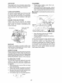
Operator's
Manual
CRRFT MRH°
LAWN TFIACTO
17.5 HR* 30" Mower
Electric Start
6-Speed Transaxle
Model No.
917.28035
• EspaSol, pg. 33
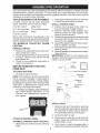
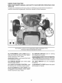
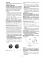
This product has a low emission
engine which operates
differently from previously built engines. Before you start the
engine, read and understand this Owner's Manual.
IMPORTANT:
Read and follow all Safety
Rules and Instructions before
operating this equipment.
For answers to your questions
about this product, Call:
1-800-659-5917
Sears Craftsman Help Line
5 am-5
pm, Mon-Sat
SEARS, ROEBUCK AND CO., HOFFMAN ESTATES, IL 60179 U.S.A.
Visit our Craftsman website:www.sears.com/craftsman
*As rated by the engine
433804 Rev. 1
manufacturer
Warranty ..................................................
2
Safety Rules ............................................
3
Product Specifications ............................. 6
Assembly/Pre-Operation
......................... 8
Operation ...............................................
11
Maintenance Schedule .......................... 17
Maintenance ..........................................
17
Service and Adjustments ....................... 21
Storage ..................................................
27
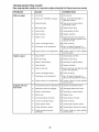
Troubleshooting .....................................
28
Sears Service .......................... Back Cover
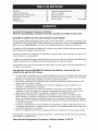
Craftsman Riding Equipment Warranty:
Lawn Tractors, Garden Tractors, Zero Turn Riders
CRAFTSMAN
TWO YEAR FULL WARRANTY
FOR TWO YEARS from the date of purchase, if any non-expendable
part of this riding
equipment fails due to a defect in material or workmanship, visit www.craftsman.com
or
call 1-800-659-5917 to arrange for free in-home repair.
The frame and front
purchase
if defective
In all cases, if repair
charge with the same
axle will be repaired free of charge
in material or workmanship.
proves impossible,
the
or an equivalent
model.
The battery will be replaced
free of charge for 90 days from the date of purchase
defective
in material or workmanship
(our testing proves that it will not hold a charge).
if
This warranty covers ONLY defects
coverage does NOT include:
*
*
*
*
*
*
*
*
in material
providing
will
be replaced
of
of
is ever used while
equipment
from the date
free
This warranty is void if this product
rented to another person.
riding
for five years
commercial
and workmanship.
services
or if
Warranty
Expendable
items that can wear out from normal use within the warranty period,
including but not limited to blades, spark plugs, air cleaners,
belts, and oil filters.
Standard
maintenance
servicing,
oil changes, or tune-ups.
Tire replacement
or repair caused by punctures from outside objects, such as nails,
thorns, stumps, or glass.
Tire or wheel replacement
or repair resulting from normal wear, accident,
or improper
operation or maintenance.
Repairs necessary
because of operator abuse, including but not limited to damage
caused by towing objects beyond the capability
of the riding equipment,
impacting
objects that bend the frame or crankshaft,
or over-speeding
the engine.
Repairs necessary
because of operator negligence,
including but not limited to,
electrical and mechanical
damage caused by improper storage, failure to use the
proper grade and amount of engine oil, failure to keep the deck clear of flammable
debris, or failure to maintain the riding equipment
according
to the instructions
contained
in the operator's
manual.
Engine (fuel system) cleaning or repairs caused by fuel determined
to be
contaminated
or oxidized
(stale). In general, fuel should be used within 30 days of its
purchase
date.
Normal deterioration
and wear of the exterior finishes, or product label replacement.
This warranty gives you specific
vary from state to state.
Sears
Brands
Management
legal
rights,
Corporation,
and you may also have
Hoffman
2
Estates,
other
IL 60179
rights
which
_,DANGER:
This cutting
machine
is capable
of amputating
hands
throwing
objects.
Failure to observe the following
safety instructions
in serious
injury or death.
_I_IWARNING:
In order to prevent accidental starting when setting up, transporting,
adjusting or making repairs, always disconnect spark plug wire and place wire where
it cannot contact spark plug.
•
_WARNING:
Do not coast down a hill in
neutral, you may lose control of the tractor.
•
_IWARNING:
Tow only the attachments
that are recommended by and comply with
specifications of the manufacturer of your
tractor. Use common sense when towing.
Operate only at the lowest possible speed
when on a slope. Too heavy of a load, while
on a slope, is dangerous.
Tires can lose
traction with the ground and cause you to
lose control of your tractor.
AI_IWARNING:
Engine exhaust, some of
its constituents, and certain vehicle components contain or emit chemicals known to the
State of California to cause cancer and birth
defects or other reproductive harm.
•
•
•
•
•
•
_jLWARNING:
Battery posts, terminals and
related accessories
contain lead and lead
•
compounds,
chemicals known to the State of
California to cause cancer and birth defects
•
or other reproductive
after handling.
•
I. GENERAL
•
•
•
•
•
•
•
harm.
Wash
hands
OPERATION
Read, understand,
and followall
instructions on the machine and in the manual
before starting.
Do not put hands or feet near rotating
parts or under the machine.
Keep clear
of the discharge
opening at all times.
Only allow responsible
adults, who are
familiar with the instructions,
to operate
the machine.
Clear the area of objects such as rocks,
toys, wire, etc., which could be picked
up and thrown by the blades.
Be sure the area is clear of bystanders
before operating.
Stop machine if anyone
enters the area.
Never carry passengers.
Do not mow in reverse unless absolutely
necessary. Always look down and behind
before and while backing.
•
•
and feet and
could result
Never direct discharged
materialtoward
anyone.
Avoid
discharging
material
against a wall or obstruction.
Material
may ricochet back toward the operator.
Stop the blades when crossing
gravel
surfaces.
Do not operate machine without the entire grass catcher, discharge
chute, or
other safety devices in place and working.
Slow down before turning.
Never leave a running
machine
unattended.
Always
turn off blades,
set
parking brake, stop engine, and remove
keys before dismounting.
Disengage
blades when not mowing.
Shut off engine and wait for all parts to
come to a complete stop before cleaning
the machine, removing the grass catcher,
or unclogging
the discharge
chute.
Operate machine onlyin daylight or good
artificial light.
Do not operate the machine while under
the influence
of alcohol or drugs.
Watch for traffic when operating
near or
crossing roadways.
Use extra care when loading or unloading
the machine
into a trailer or truck.
AIways wear eye protection when operating machine.
Data indicates
that operators,
age 60
years and above, are involved in a large
percentage
of riding mower-related
injuries. These operators
should evaluate
their ability to operate the riding mower
safely enough to protect themselves
and
others from serious injury.
Follow the manufacturer's
recommendation for wheel weights
or counterweights.
Keep machine free of grass,
leaves or
other debris build-up which can touch hot
exhaust / engine parts and burn. Do not
allow the mower to plow leaves or other
debris which can cause build-up to occur. Clean any oil or fuel spillage before
operating or storing the machine. Allow
machine to cool before storage.
Ii. SLOPE OPERATION
Slopes are a major factor related to loss of
control and tip-over
accidents,
which can
result in severe injury or death.
Operation
on all slopes requires extra caution.
If you
cannot back up the slope or ifyou feel uneasy
on it, do not mow it.
•
Mow up and down slopes, not across.
•
Watch for holes, ruts, bumps, rocks, or
other hidden
objects.
Uneven terrain
could overturn the machine.
Tall grass
can hide obstacles.
•
•
•
•
•
•
•
Choose a low ground speed so that you
will not have to stop or shift while on the
slope.
Do not mow on wet grass. Tires may lose
traction.
Never
chine.
•
Use extra care when approaching
blind
corners, shrubs, trees, or other objects
that may block your view of a child.
allow children
to operate
the ma-
Always keep the machine in gear when
going down slopes. Do not shift to neutral
and coast downhill.
•
Tow only with a machine that has a hitch
designed for towing. Do not attach towed
equipment
except at the hitch point.
Followthemanufacturer'srecommenda-
Avoid starting, stopping, or turning on a
slope. Ifthetires
Iosetraction,
disengage
the blades and proceed slowly straight
down the slope.
Keep all movement
on the slopes slow
and gradual.
Do not make sudden
changes
in speed or direction,
which
could cause the machine to roll over.
•
tion for weight limits for towed equipment
and towing on slopes.
Never allow children or others in or on
Use extra care while operating machine
with grass catchers or other attachments;
they can affect the stability
of the machine. Do no use on steep slopes.
Do not try to stabilize the machine
by
putting your foot on the ground.
Do not mow near drop-offs,
ditches,
or embankments.
The machine
could
V. SERVICE
•
•
and the mowing
activity.
that children
will remain
saw them.
Travel slowly
stop.
and allow extra distance
to
OF GASOLINE
To avoid personal
injury or property
damage, use extreme care in handling gasoline.
Gasoline
is extremely
flammable
and the
vapors are explosive.
•
Extinguish
all cigarettes,
cigars, pipes,
and other sources of ignition.
•
Use only approved
gasoline container.
•
Never remove gas cap or add fuel with
the engine running. Allow engine to cool
before refueling.
•
Never fuel the machine indoors.
•
Neverstorethe
machine orfuel container
Never assume
where you last
•
Keep children out of the mowing area
and in the watchful care of a responsible
adult other than the operator.
Be alert and turn machine off if a child
enters the area.
Before and while backing, look
and down for small children.
towed equipment.
On slopes, the weight ofthetowed
equipment may cause loss of traction and loss
of control.
SAFE HANDLING
Tragic accidents
can occur if the operator
is not alert to the presence
of children.
Children are often attracted to the machine
•
•
•
Ii1. CHILDREN
•
Never
carry children,
even with the
blades shut off. They may fall off and
be seriously injured or interfere with safe
machine operation.
Children who have
been given rides in the past may suddenly
appear in the mowing area for another
ride and be run over or backed over by
the machine.
IV. TOWING
suddenly
roll over if a wheel is over the
edge or if the edge caves in.
•
•
•
behind
where there is an open flame, spark,
pilot light such as on a water heater
other appliances.
Never fill containers
inside a vehicle
on a truck or trailer bed
Always place containers
away from your vehicle
Remove gas-powered
the truck or trailer and
or
or
or
with plastic liner.
on the ground
when filling.
equipment
from
refuel it on the
ground. If this is not possible, then refuel
such equipment with a portable container,
rather than from a gasoline
dispenser
nozzle.
4
•
•
•
Keep the nozzle in contact with the rim
of the fuel tank or container
opening at
all times until fueling is complete.
Do not
use a nozzle lock-open
device.
Iffuel is spilled on clothing, change clothing immediately.
Never overfill fuel tank. Replace gas cap
and tighten securely.
GENERAL
SERVICE
•
•
•
Never
area.
•
Keep all nuts and bolts tightto be sure the
equipment
is in safe working condition.
Nevertamperwithsafetydevices.
Check
their proper operation
regularly.
Keep machine free of grass, leaves, or
other debris build-up.
Clean oil or fuel
spillage and remove any fuel-soaked
debris. Allow machine to cool before storing.
•
Do not mow in reverse unless absolutely
necessary. Always look down and behind
before and while backing.
Never
carry children,
even with the
blades shut off. They may fall off and
be seriously injured or interfere with safe
machine operation.
Children who have
been given rides in the past may suddenly
appear in the mowing area for another
ride and be run over or backed over by
the machine.
•
Before and while backing,
look behind
and down for small children.
•
Mow up and down
across.
•
Keep children
out of the mowing
area
and in the watchful care of a responsible
adult other than the operator.
Be alert and turn machine
off if a child
enters the area.
•
Choose a low ground speed so that you
will not have to stop or shift while on the
slope.
Avoid starting, stopping,
or turning on a
slope. Ifthetires Iosetraction,
disengage
the blades and proceed slowly straight
down the slope.
If machine
stops while going
uphill,
disengage
blades, shift into reverse and
back down slowly.
Do not turn on slopes unless necessary,
and then, turn slowly
and gradually
downhill, if possible.
•
•
•
•
•
machine
in a closed
If you strike a foreign object, stop and
inspectthe machine. Repair, if necessary,
before restarting.
Never make any adjustments or repairs
with the engine running.
Checkgrasscatchercomponents
andthe
discharge chute frequently and replace
with manufacturer's recommended parts,
when necessary.
Mower blades aresharp. Wrapthe blade
or wear gloves, and use extra caution
when servicing them.
Check brake operation frequently. Adjust
and service as required.
Maintain or replace safety and instruction
labels, as necessary.
Be sure the area is clear of bystanders
before operating. Stop machine ifanyone
enters the area.
Never carry passengers.
•
•
operate
•
•
•
•
•
•
slopes
(15 ° Max), not
PRODUCT
Gasoline
Capacity
and Type:
1.50 Gallons
Unleaded
Regular
Oil Type
API-SG-SL):
SAE 30 (above 32°F)
SAE 5W30 (below 32°F '
Oil Capacity:
48 oz.
Spark
Champion
RC12YC
(Gap: .030")
Plug:
Ground
Speed
Charging
System:
Battery:
Blade
REPAIR PROTECTION
AGREEMENTS
SPECIFICATIONS
Forward:
Reverse:
3 Amps
5 Amps
0- 5.2
0- 2.9
Battery
Headlights
Amp/Hr:
Min. CCA:
Case size:
Bolt Torque:
Congratulations on making a smart purchase.
Your new Craftsman® product is designed
and manufactured for years of dependable
operation. But like all products, it may require
repair from time to time. That's when having
a Repair Protection Agreement can save you
money and aggravation.
Purchase a Repair Protection Agreement
now and protect yourself from unexpected
hassle and expense.
Here's what's included in the Agreement:
•
28
230
U1R
Expert service by our 12,000
repair specialists.
profesional
Unlimited service and no charge for parts
and labor on all covered repairs.
45 - 55 Ft. Lbs.
Product replacement
if your covered
product can't be fixed.
CONGRATULATIONS
on your purchase of
a new tractor. It has been designed, engineered and manufactured to give you the best
possible dependability
and performance.
Should you experience any problem you cannot easily remedy, please contact a Sears or
other qualified service center. We have competent, well-trained representatives and the
proper tools to service or repair this tractor.
Please read and retain this manual. The
instructions will enable you to assemble
and maintain your tractor properly. Always
observe the "SAFETY RULES".
Discount
of 10% from regular price of
service
and service-related
parts not
covered bythe agreement;
also, 10% off
regular price of preventive
maintenance
check.
Fast help by phone-phone support from
a Sears representative on products requiring in-home repair, plus convenient
repair scheduling.
Once
you purchase
the Agreement,
a
simple phone call is all that it takes for you
to schedule
service. You can call anytime
day or night, or schedule a service appointment online.
CUSTOMER
RESPONSiBiLITiES
• Read and observe the safety rules.
• Follow a regular schedule in maintaining,
caring for and using your tractor.
• Follow the instructions
under "Maintenance" and "Storage" sections of this
owner's manual.
Sears has over 12,000 professional
repair
specialists,
who have access to over 4.5
million quality parts and accessories.
That's
the kind of professionalism
you can count on
to help prolong the life of your new purchase
for years to come. Purchase
your Repair
Protection Agreement
today!
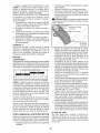
_IbWARNING: This tractor is equipped with
an internal combustion engine and should not
be used on or near any unimproved forestcovered, brush-covered
or grass-covered
land unless the engine's exhaust system is
equipped with a spark arrester meeting applicable local or state laws (if any). If a spark
arrester is used, it should be maintained in
effective working order by the operator.
In the state of California the above is required
by law (Section 4442 of the California Public
Resources Code). Other states may have
similar laws. Federal laws apply on federal
lands. A spark arrester for the muffler is
available through your nearest Sears service
center (See REPAIR PARTS manual).
Some limitations
and exclusions
apply.
For prices and additional
information
call
1-800-827-6655.
SEARS
iNSTALLATION
SERVICE
For Sears professional installation of home
appliances,
garage door openers, water
heaters, and other major home items, in the
U.S.A. call 1-800-4-MY-HOME®
6
Bagger
Steering
/
/
Wheel
\
/
\
/
I
1/4 x 20 x 1.25"
Carriage
1/4x20x
Shoulder
Bolts
Steering
Wheel Insert
Steering
Wheel
1.15
Bolts
Steering Wheel
Adapter
Steering
Boot
3
(1) Bolt
I
1/4 x 20
Steering
Extension
Flange Lock Nuts
Shaft
Retainer
I
Spring clip
(1) Large
Flat Washer
Clevis Pin
(1) Lock
Washer
Seat
Slope
(1) Washer
(1) Seat
(1/Bolt
Key(s)
Sheet
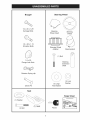
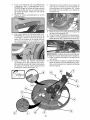
Your new tractor has been assembled
at the factory with the exception
of those parts left
unassembled
for shipping purposes.
To ensure safe and proper operation
of your tractor
all parts and hardware you assemble
must be tightened
securely. Use the correct tools as
necessary to ensure proper tightness.
TOOLS REQUIRED
FOR ASSEMBLY
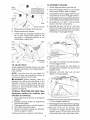
2. Place tabs of steering boot over tab slots
in dash and push down to secure.
A socket wrench set will make assembly
easier. Standard wrench sizes are listed.
(1) 5/16"
wrench
Utility knife
(2) 7/16"
wrenches
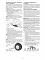
Tire pressure
Pliers
(2) 1/2" wrenches
(1) 9/16"
INSTALL
2.
3.
gauge
wrench
Remove all accessible
loose parts and
parts boxes from carton.
Cut along dashed lines on all four panels
of carton. Remove end panels and lay
side panels flat.
Check for any additional
loose parts or
cartons and remove.
BEFORE REMOVING
FROM SKID
JJ-- -.
Lock
Bolt __Washer
-- _:_-/
Lift seat to raised
position.
•
for charging
Lower
Steering
S haft
section
Label
,
STEERING
3.
WHEEL
EXTENSION
1. Slide extension
shaft.
-_teedn,_
_
UBoot
,
Extension
__Shaff
i
,,_:_ , _.
\\\
.
ASSEMBLE
Steering
ee
in
INSTALL
ATTACH
Flat Washer
,,
:-'-_":
....
,,,/,_
Adapter
,_:_
-_-_1
instructions).
Adjustments"
• ....
x
,,
'_ " _:_........ _' "
_,....
.... o--_
For battery and battery cable installation
see "REPLACING
BATTERY"
in the
"Service
and
this manual.
-
-(
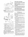
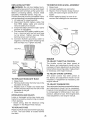
NOTE: If this battery is put into service after
month and year indicated
on label (label is
located between terminals)
charge battery
for minimum of one hour at 6-10 amps. (See
"BATTERY"
in Maintenance
section of this
manual
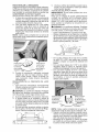
Insert
TRACTOR
TO CHECK BATTERY
1.
WHEEL
3. Position front wheels of the tractor so
they are pointing straight forward.
4. Remove steering wheel adapter from
steering wheel and slide adapter onto
steering shaft extension.
5. Position steering wheel so cross bars are
horizontal (left to right) and slide inside
boot and onto adapter.
6. Assemblelargeflatwasher,
Iockwasher,
bolt and tighten securely.
7. Snap steering wheel insert into center of
steering wheel.
8. Remove protective materialsfromtractor
hood and grill.
IMPORTANT: Check for and remove any
staples in skid that may puncture tires where
tractor is to roll off skid.
When right or left hand is mentioned in this
manual, itmeanswhenyouareintheoperating
position (seated behind the steering wheel).
TO REMOVE
TRACTOR
FROM
CARTON
U NPAC K CARTO N
1.
STEERING
lower steering
.
8
Remove
bolt and flat washer securing
seat to cardboard
packing and set aside
for assembly
of seat to tractor. Remove
the cardboard
packing and discard.
Connect
switch
to seat.
Place seat on seat pan so all three (3)
bottom pads are positioned
over large
slotted holes in pan.
SHAFT AND BOOT
shaftonto
SEAT
Push down on seat to engage
pads in
slots and pull seat towards rear of tractor.
TO ASSEMBLY
Tape
"_
Wiring harness
5.
Raise seat and tighten
6.
Remove
7.
Lower seat into operating
position and
sit on seat. Press brake pedal all the
way down. If operating
position
is not
comfortable,
adjust seat.
1.
Unfold
2.
Feed front bagger frame (1) up through
fabric loops at each side of bagger.
3.
Snap bottom offrontbaggerframe
snap feature at front of bagger
4.
Slidebaggerfabricloop(2)
segmentsatthe
ends of bag onto top bagger frame tubing.
5.
Uninstall two (1\4"-20 x 1.15") hex bolts
(3) from the front of top frame.
6.
Reinstall the two (1\4"-20 x 1.15") hex
bolts (3) through holes at top of the front
bagger frame and thread into nuts inside
the tubing of top bagger frame.
7.
Uninstall (1/4"-20)lock
of front bagger frame.
8.
Unfold cross braces
(5) and attach to
carriage bolts at bottom corners of front
bagger frame.
9.
Reinstall
(1/4"-20)
lock
tighten until fully seated.
bolt securely.
tape and discard.
Slot
BAGGER
bag and stand
right side up.
(1)into
bottom.
Tape
Pad
Flat
washer
Seat
Bolt
pan
Tab
Adjustment
handle
TO ADJUST
SEAT
Grasp adjustment
handle and pull up, slide
seat to desired position and release adjustment handle.
NOTE: You may now roll your tractor off
the skid. Follow the instructions
below to
remove the tractor from the skid.
nuts (4) atbottom
nuts
(4)
and
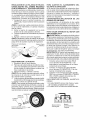
WARNING:
Before starting,
read, understand
and follow all instructions
in the
Operation
section of this manual. Be sure
tractor is in a well-ventilated
area. Be sure
the area in front of tractor is clear of other
people and objects.
TO
ROLL
TRACTOR
Operation
function
1.
2.
3.
4.
5.
OFF
section
of
for
SKID
location
(See
and
controls)
Raise attachment
lift lever to its highest
position,
Release
parking
brake by depressing
clutch/brake
pedal,
Place gearshift lever in neutral position.
Roll tractor forward off skid,
Remove
banding
shield up against
Continue
holding
tractor,
with the instructions
the deflector
that follow.
10. Remove clevis pin (6) and retainer
(7) from bagger handle (8).
11. Slide bagger handle (8) down through
gercoverandframeupperweldmentholes.
spnng
bag-
12. Reinstall
clevis
pin (6) through
hole
at bottom of bagger handle
and slide
retainer spring (7) into hole at the end
of the clevis pin until it locks into place
CHECK
DECK
LEVELNESS
For best
should be
MOWER"
section of
cutting results, mower housing
properly leveled. See "TO LEVEL
in the Service and Adjustments
this manual.
CHECK FOR PROPER
POSITION
OF
ALL BELTS
See the figures that are shown for replacing
motion and mower blade drive belts in the
Service and Adjustments section of this manual. Verify that the belts are routed correctly.
TO ADJUST
PADDLE
BAGGER
FULL
CHECK BRAKE
SYSTEM
After you learn how to operate your tractor,
checkto see that the brake is operating properly. See "TO CH ECK BRAKE" in the Service
and Adjustments section of this manual.
LEVER/
1. Before adjusting, tractor engine must be
shut off and parking brake engaged.
J
CHECKLIST
Before you operate
your new tractor, we
wish to assure that you receive the best
performance
and satisfaction
from this
Quality Product.
Please review the following
checklist:
_f All assembly
instructions
have been
completed.
_f No remaining
_f Battery
loose
is properly
J" Seat is adjusted
ened securely.
prepared
comfortably
and charged.
and tight-
_f All tires are properly inflated.
(For shipping purposes, the tires were overinflated
at the factory).
_f Be sure mower deck is properly leveled
side-to-side/front-to-rear
for best cutting
results.
(Tires must be properly inflated
for leveling).
_f Check mower and drive belts.
Be sure
2.
For the heaviest/wet
paddle (3).
3.
For lighter grasses use the paddle (3) on
setting "1", "2", or "3" ("3" being for the
lightest or dry grass).
they are routed properly around pulleys
and inside all belt keepers.
_/Check
wiring. See that all connections
are
still secureand wires are properlyclamped.
4.
Choose
bagger
number
While learning how to use your tractor, pay extra attention to the following important items:
5.
Setting
may be changed
by loosening
fasteners
(4 and 5), removing/rotating
paddle (3), and tightening
again.
CHECK
grasses,
parts in carton.
remove
your setting
and rotate
the
paddle (3) so that the desired
(setting) faces you.
TIRE
_/Engine
oil is at proper
level.
_f Fuel tank is filled with fresh, clean, regular
unleaded
gasoline.
_f Become
familiar with all controls,
their
PRESSURE
location
and function.
Operate
before you start the engine.
The tires on your tractor were overinflated
atthe factory for shipping purposes. Correct
tire pressure is important for best cutting
performance.
• Reduce tire pressure to PSI shown on
tires.
_f Be sure brake system
condition.
them
is in safe operating
_f Be sure Operator Presence System and
Reverse
Operation
System
(ROS) are
working properly (See the Operation and
Maintenance
sections in this manual).
10
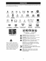
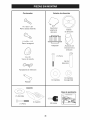
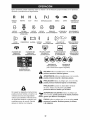
These symbols may appear on your tractor or in literature suppliedwith the product. Learn
and understandtheir meaning,
R
REVERSE
ENGINE
OFF
H
L
NEUTRAL
HIGH
LOW
REVERSE
OPERATION
ENGINE
ON
ENGINE
I',,I ¢
CHOKE
START
FAST
PARKING
IGNITION SWITCH
SLOW
BRAKE
MOWER
HEIGHT
MOWER
LIFT
SYSTEM (ROS)
t
LIGHTS ON
FUEL
ATTACHMENT
CLUTCH DISENGAGED
BATTERY
ATTACHMENT
CLUTCH ENGAGED
REVERSE
FORWARD
CRUISE
DANGER, KEEP HANDS
AND FEET AWAY
CONTROL
CLUTCH/BRAKE
PEDAL
OPERATE
ONLY
WiTH BAGGER
DO NOT OPERATE
WITHOUT
BAGGER
@@®@@
KEEP AREA
CLEAR
(SEE SAFETY
FREE WHEEL
(Automatic
Models only)
&
Failure to follow instructions
could result in serious injury or
death. The safety alert symbol
is used to identify safety information about hazards which can
result in death, serious injury
and/or property damage.
&
&
&
SLOPE
RULES
HAZARDS
SECTION)
DANGER indicates a hazard which, if not avoided,
will result in death or serious injury.
WARNING indicates a hazard which, if not avoided,
could result in death or serious injury.
CAUTION indicates a hazard which, if not avoided,
might result in minor or moderate injury.
CAUTION when used without the alert symbol,
indicates a situation that could result in damage
to the tractor and/or engine.
HOT SURFACES indicates a hazard which,
if not avoided, could result in death, serious
,_hlJlll_lJlil,,
and/or property damage.
FIRE indicates a hazard which, if not avoided,
could result in death, serious injury and/or
property damage.
11
injury
KNOW YOUR TRACTOR
READ THIS OWNER'S MANUAL AND SAFETY
TRACTOR
RULES BEFORE
OPERATING
YOUR
Compare the illustrations with your tractor to familiarize yourself with the locations of
various controls and adjustments. Save this manual for future reference.
Our tractors
conform
American
to the applicable
safety standards
National Standards
Institute.
(F) IGNITION SWITCH-Used
and stopping the engine.
(A) ATTACHMENT
LIFT LEVER-Used
to
raise and lower the mower or other attachments
mounted
to your tractor.
(B) BRAKE PEDAL-Used
and starting the engine.
for starting
(G) REVERSE OPERATION SYSTEM (ROS)
"ON" POSmON-Allows
operation of mower
or other powered attachment while in reverse.
braking the tractor
(C) PARKING BRAKE-Locks
into the brake position.
of the
brake pedal
(H) LIGHT
on and off.
(D) THROTTLE/CHOKE
CONTROL-Used
for starting and controlling engine speed.
SWITCH-Turns
the
(J) GEARSHIFT LEVER-Selects
and direction of tractor.
(E) ATTACHMENT CLUTCH LEVER-Used
to engage the mower blades, or other attachments mounted to your tractor.
12
headlights
the speed
The operation of any tractor can result in foreign objects thrown into
the eyes, which can result in severe eye damage. Always wear safety
glasses or eye shields while operating your tractor or performing any
adjustments or repairs. We recommend standard safety glasses or a
wide vision safety mask worn over spectacles.
• Never use choke to stop engine.
IMPORTANT:
Leaving the ignition switch in
any position other than "STOP" will cause
the battery to discharge
and go dead.
NOTE:
Under certain
conditions
when
HOW TO USE YOUR TRACTOR
TO SET PARKING
BRAKE
Your tractor is equipped
with an operator
presence
sensing
switch. When engine is
running, any attempt by the operator to leave
the seat withoutfirst
setting the parking brake
will shut off the engine.
1. Depress brake pedal (B) all the way down
and hold.
2.
tractor is standing
idle with the engine running, hot engine exhaust gases may cause
"browning"
of grass. To eliminate
this possibility, always stop engine when stopping
tractor on grass areas.
Pull parking brake lever (C) up and hold,
release pressure
from brake pedal (B),
then release parking brake lever. Pedal
should remain in brake position.
Make
sure parking brake will hold tractor secure.
_IbCAUTION:
Always
stop tractor
pletely, as described
above,
the operator's
position.
TO USE THROTTLE
before
CONTROL
comleaving
(D)
Always operate engine at full speed (fast).
• Operating
engine at less than full speed
(fast) reduces engine's operating efficiency.
• Full speed (fast) offers the best mower
performance.
STOPPING
MOWER
BLADES
• To stop mower
clutch
blades,
move attachment
lever to disengaged
position
(¢'_).
TO MOVE FORWARD AND BACKWARD
The direction and speed of movement
is
controlled by the gearshift lever (J).
(t_)
(¢_)Attachment
Clutch Lever
"Disengaged"
Attachment
Clutch Lever
"Engaged"
GROUND
DRIVE
-
• To stop ground drive, depress clutch/brake
pedal all the way down.
• Move gearshift lever to neutral position.
1.
ENGINE• Move throttle control between
speed (fast) position.
NOTE:
Failure to move throttle
half and full
control
2.
3.
be-
tween half and full speed (fast) position, before stopping, may cause engine to "backfire".
• Turn ignition keyto"STOP"
position and remove key. Always remove key when leaving tractor to prevent unauthorized
use.
Start tractor
with clutch/brake
pedal
depressed
and gearshift lever in neutral
position.
Move gearshift lever to desired position.
Slowly release clutch/brake
pedal to start
movement.
IMPORTANT:
Bring tractor to a complete
stop before
shifting
or changing
gears.
Failure to do so will shorten the useful life
of your transaxle.
13
TO ADJUST
MOWER
CUTTING
The position of the attachment
determines
the cutting height.
HEIGHT
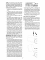
REVERSE OPERATION SYSTEM (ROS)
Your tractor is equipped with a Reverse
Operation System (ROS). Any attempt by
the operator to travel in the reverse direction
with the attachment clutch engaged will shut
off the engine unless ignition key is placed
in the ROS "ON" position.
_, WARNING: Backing up with the attachment clutch engaged while mowing is
strongly discouraged. Turning the ROS "ON",
to allow reverse operation with the attachment clutch engaged, should only be done
when the operator decides it is necessary to
reposition the machine with the attachment
engaged. Do not mow in reverse unless
absolutely
necessary.
lift lever (A)
• Put attachment
lift lever in desired cutting
height slot.
The cutting height range is approximately
1"
to 4". The heights are measured
from the
ground to the blade tip with the engine not running. These heights are approximate and may
vary depending
upon soil conditions,
height
of grass and types of grass being mowed.
• The average
lawn should be cut to approximately
2-1/2" during the cool season
and to over 3" during hot months.
For
healthier and better looking lawns, mow
often and after moderate
growth.
• For best cutting performance,
grass over
6" in height should be mowed twice. Make
the first cut relatively high; the second to
desired height.
TO OPERATE
USING THE REVERSE OPERATION
Only use if you are certain no children or
other bystanders
will enter the mowing area.
1. Depress brake pedal all the way down.
2. With engine running, turn ignition key
counterclockwise to ROS "ON" position.
3. Look down and behind before and while
backing.
4. Slowly depress reverse drive pedal to
start movement.
5. When use of the ROS is no longer
needed, turn the ignition key clockwise
to engine "ON" position.
MOWER
Your tractor is equipped
with an operator
presence sensing switch. Any attempt bythe
operator to leave the seat with the engine
running and the attachment
clutch engaged
will shut off the engine. You must remain
fully and centrally
positioned
in the seat to
prevent the engine from hesitating or cutting
offwhen operating your equipment on rough,
rolling terrain or hills.
1. Select desired
ment lift lever.
2.
height
TO STOP
1.
MOWER
Disengage
ROS "ON" Position
• Raise attachment
lift lever to its highest.
• When pushing or towing your tractor, be
sure gearshift lever is in neutral position.
• Do not push or tow tractor at more than
five (5) MPH.
NOTE: To protect hood from damage when
transporting
your tractor on atruck or atrailer,
be sure hood is closed and secured to tractor.
attach-
BLADE
attachment
clutch
Engine "ON" Position
(Normal Operating)
TO TRANSPORT
of cut with attach-
Start mower blade by engaging
ment clutch control.
SYSTEM
control.
CAUTION:
Do not operate
machine
without the entire grass catcher,
or other
safety devices in place and working
Use an appropriate
means
tractor (rope, cord, etc.).
of tying hood to
TOWING CARTS AND OTHER ATTACHMENTS
Tow only the attachments that are recommended by and comply with specifications
of the manufacturer
of your tractor. Use
common sense when towing. Too heavy of
a load, while on a slope, is dangerous. Tires
can lose traction with the ground and cause
you to lose control of your tractor.
/
/
/
/
14
TO OPERATE
ON HILLS
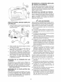
CAUTION: Alcohol blended fuels (called
gasohol or using ethanol or methanol) can
attract moisture which leads to separation
and formation of acids during storage. Acidic
gas can damage the fuel system of an engine
while in storage. To avoid engine problems,
the fuel system should be emptied before
storage of 30 days or longer. Drain the gas
tank, start the engine and let it run until the
fuel lines and carburetor are empty. Use fresh
fuel next season. See Storage Instructions
for additional information. Never use engine
or carburetor cleaner products in the fuel tank
or permanent damage may occur.
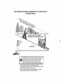
WARNING: Do not drive up or down
hills with slopes greater than 15 ° and do not
drive across any slope. Use the slope guide
provided at the back of this manual.
• Choose the slowest speed before starting
up or down hills.
• Avoid stopping or changing speed on hills.
• If stopping is absolutely necessary, push
brake pedal quickly to brake position and
engage parking brake.
• To restart movement, slowly release parking brake and brake pedal.
• Slowly depress appropriate drive pedal to
slowest setting.
• Make all turns slowly.
BEFORE
CHECK
STARTING
TO START ENGINE
When starting the engine for the first time or
if the engine has run out of fuel, it will take
extra cranking time to move fuel from the
tank to the engine.
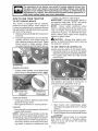
1. Siton seat in operating position, depress
clutch/brake
pedal and set parking brake.
2. Place gear shift lever in neutral position.
3. Move attachment
clutch to disengaged
position.
4. Move throttle control to choke position.
NOTE:
Before starting, read the warm and
cold starting procedures
below.
5. Insert key into ignition and turn key
clockwise
to start position and release
key as soon as engine starts. Do not run
starter continuously
for more than fifteen
seconds per minute. If the engine does
not start after several
attempts,
move
throttle
control to fast position,
wait a
few minutes and try again. If engine still
does not start, move the throttle control
back to the choke position and retry.
THE ENGINE
ENGINE OIL LEVEL
The engine in your tractor has been shipped,
from the factory, already filled with summer
weight oil.
1. Check engine oil with tractor on level
ground.
2. Remove oil fill cap/dipstick and wipe clean,
reinsert the dipstick and screw cap tight,
wait for a few seconds, remove and read
oil level. If necessary, add oil until "FULL'
mark on dipstick is reached. Do not overfill.
• For cold weather operation you should
change oil for easier starting (See the oil
viscosity chart in the Maintenance section
of this manual).
• Tochangeengineoil,seetheMaintenance
section in this manual.
ADD
GASOLINE
• Fillfueltankto
bottom
offiller
neck. Do not
WARM
WEATHER
C and above)
overfill. Use fresh, clean, regular unleaded
gasoline with a minimum
of 87 octane.
(Use of leaded gasoline will increase carbon and lead oxide deposits and reduce
valve life). Do not mix oil with gasoline. Purchase fuel in quantities that can be used
within 30 days to ensure fuel freshness.
STARTING
(50°F/10
°
6.
When engine starts, move the throttle
control to the fast position.
• The attachments
and ground drive can
now be used. Ifthe engine does not accept
the load, restart the engine and allow it to
warm up for one minute using the choke
as described
above.
ACAUTION:
Wipe off any spilled oil or fuel.
Do not store, spill or use gasoline near an
open flame.
COLD WEATHER
and above)
6.
STARTING
(50°F/10
° C
When engine starts, leavethrottle
control
in choke position until engine warms up
and begins to run roughly. Once rough
running begins,
immediately
move the
throttle control to the fast position. Engine
warm-up maytake from several seconds
to several minutes (the colder the temperature, the longer the warm-up).
• The attachments
can also be used during
the engine warm-up
period.
IMPORTANT:
When operating
in temperatures below 32°F (0°C), use fresh, clean
winter grade gasoline to help ensure good
cold weather starting.
15
NOTE: If at a high altitude (above 3000
feet) or in cold temperatures (below32° F)
the carburetor fuel mixture may need to be
adjustedfor best engine performance (see
"TOADJUSTCARBURETOR"intheService
and Adjustments section of this manual).
MAX 1/3"
•
MOWING TiPS
•
•
•
•
•
•
•
Tire
chains
cannot
be used
when
the
mower housing is attached to tractor.
Mowershould
be properlyleveled
for best
mowing performance.
See "TO LEVEL
MOWER HOUSING"
in the Service and
Adjustments
section of this manual.
The left hand side of mower should
•
then change to east to west the next
week. This will help prevent matting and
graining of the lawn.
be
used for trimming.
Ifgrassisextremelytall,
itshould bemowed
twice to reduce load and possible fire hazard from dried clippings. Makefirst cut relatively high; the second tothe desired height.
Donotmowgrasswhenitiswet.
Wetgrass
will plug mower and leave undesirable
clumps. AIIowgrassto
dry before mowing.
Always
operate
engine
at full throttle
when mowing to assure better mowing
performance
and proper discharge
of
material.
Regulate
ground
speed
by
selecting a low enough gear to give the
mower cutting performance
as well as
the quality of cut desired.
When operating
attachments,
select a
ground speed that will suittheterrain
and
give best performance
of the attachment
being used.
MULCHING
MOWING
Certain types of grass and grass conditions may require that an area be mulched
a second time to completely
hide the clippings. When doing a second cut, mow
across (perpendicular)
to the first cut path.
Change your cutting pattern from week
to week.
Mow north to south one week
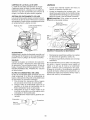
TO DUMP BAGGER
Your tractor is equipped
with a Dump
Alarm. To turn off the alarm disengage
attachment
clutch switch.
• Position
tractor in location
you wish to
dump bagger.
• Place motion control lever in neutral position and set parking brake.
• Raise dump handleto its highest position.
Pull handle forward to raise bagger and
dump clippings.
• To continue
mowing,
be sure bagger is
down and in proper operating
position to
allow mower to operate.
TiPS
IMPORTANT:
For best performance,
keep
mower housing free of built-up grass and
trash. Clean after each use.
•
•
•
Bag
the
The special mulching blade will recut the
grass clippings
many times and reduce
them in size so that as they fall onto the
lawn they will disperse into the grass and
not be noticed. Also, the mulched grass will
biodegrade quicklyto provide nutrients for
the lawn. Always mulch with your highest
engine (blade) speed as this will provide
the best recutting action of the blades.
Avoid cutting your lawn when it is wet.
Wet grass tends to form clumps and
interferes with the mulching action. The
best time to mow your lawn is the early
afternoon.
At this time the grass has
dried, yet the newly cut area will not be
exposed to direct sunlight.
For best results, adjustthe
mower cutting
height so that the mower cuts off only the
top one-third
of the grass blades.
For
extremely
heavy mulching,
reduce your
width of cut on each pass and mow slowly.
/
\
',,,
i
i,
it.. !,L
.....
16
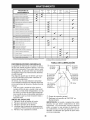
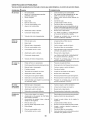
MAINTENANCE
SCHEDULE
Check
Brake
BEFORE
EACH
USE
Operation
Check
Operator
A
Check
for Loose
C
Check/Replace
T
Lubrication
0
Check
Battery
R
Clean
Battery
Clean
Debris
Presence
i
EVERY
EVERY
EVERY
BEFORE
25
HOURS
50
HOURS
100
HOURS
SEASON
STORAGE
t/
t/
& ROS Systems
t,,'
i/
Fasteners
Mower
i,,"
i/4
t/
Level
and Terminals
Off Steering
Mower
t/
i/
Plate
i/
Cooling
t/
Levelness
i/
Check V-Belts
Check
tf
Blades
Chart
Check Transaxle
Check
EVERY
8
HOURS
_
Check Tire Pressure
RT
EVERY
Engine
Oil Level
Change Engine Oil (with oil filter)
v'
i
E
Change
Engine Oil (without
IN
Clean
Air Filter
G
Clean
Air Screen
oil filter)
t/'2
Inspect Muffler/Spark
Attester
N
Replace Oil Filter (if equipped)
E
Clean
Engine
Replace
Cooling
Spark
I/2
t/
Fins
Plug
Replace Air Filter Paper Cartridge
__
I/
R.e_place Fuel Filter
1 - Change
2 - Service
more
more
often
often
when
when
GENERAL
operating
operating
under
in dirty
a heavy
or dusty
load
or
in high
ambient
temperatures.
conditions.
3 - Replace
4 - Not
more
often
if equipped
when
w_th
mowing
in sandy
maintenance-free
soil
5 - See
(_
Cleaning
in Maintenance
Section.
battery.
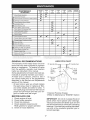
LUBRICATION
RECOMMENDATIONS
The warranty on this tractor does not cover
items that have been subjected to operator
abuse or negligence. To receive full value
from the warranty, operator must maintain
tractor as instructed in this manual.
Some adjustments will need to be made periodically to properly maintain your tractor.
At least once a season, check to see if
you should make any of the adjustments
described in the Service and Adjustments
section of this manual.
• At least once a year you should replace
the spark plug, clean or replace air filter,
and check blades and belts for wear. A
new spark plug and clean air filter assure
proper air-fuel mixture and help your engine run better and last longer.
BEFORE
blades
required
CHART
Spindle Zerk---1S--------_r--(_i.._[-!_/IIq'l''-'
Spindle Zerk
ill
@ Front
_"
Wheel
Bearing
_
_
Zerk
(_
Steering ISector
Gear Teeth
Front
_
.....
t-,
Wheel
Bearing
'_i
__,,_
__ff'i
i i!
i i! i
Zerk
\_
_: _; i
i ii i
(_
Engine
tli::L:_ZL:_:ZZZZ?ZZZZ:!I7
d)General
Purpose Grease
@Refer to Maintenance
"ENGIN
EACH USE
1.
2.
3.
4.
Check engine oil level.
Check brake operation.
Check tire pressure.
Check operator presence and
ROS systems for proper operation.
5. Check for loose fasteners.
E" Section
IMPORTANT:
Do not oil or grease the pivot
points which have special nylon bearings.
Viscous lubricants
will attract dust and dirt
that will shorten the life of the self-lubricating
bearings.
If you feel they must be lubricated,
use only a dry, powdered
graphite type lubricant sparingly.
17
TRACTOR
CHECK
SYSTEM
Always observe safety rules when performing
any maintenance.
BRAKE OPERATION
If tractor requires more than five (5) feet to
stop at highest speed in highest gear on a
level, dry concrete or paved surface, then
brake must be serviced. (See "TO CHECK
BRAKE" in the Service and Adjustments
section of this manual).
TIRES
• Maintain proper air pressure in all tires
(See the sides of tires for proper PSI).
• Keep tires free of gasoline, oil, or insect
control chemicals which can harm rubber.
• Avoid stumps, stones, deep ruts, sharp
objects and other hazards that may cause
tire damage.
NOTE: To seal tire punctures and prevent
flat tires due to slow leaks, tire sealant may
be purchased from your local parts dealer.
Tire sealant also prevents tire dry rot and
corrosion.
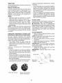
PRESENCE
SYSTEM
gaged
AND
Raise mower to highest position to allow
access to blades.
NOTE: Protect your hands with gloves and/
or wrap blade with heavy cloth.
2. Remove blade bolt by turning counterclockwise.
3. Install new blade with stamped "GRASS
SIDE" facing the ground.
IMPORTANT:
To ensure proper assembly,
center hole in blade must align with star on
mandrel assembly.
4. Install and tighten
blade bolt securely
(45-55 Ft. Lbs. torque).
IMPORTANT:
Special
blade bolt is heat
treated.
PRESENCE
• When the engine is running,
by the operator to leave the
first setting the parking brake
off the engine.
• When the engine is running
tachment
clutch is engaged,
by the operator to leave the
shut off the engine.
• The attachment
clutch should
ate unless the operator is in
REMOVAL
1.
position.
OPERATOR
any attempt
seat without
should shut
Star
\
Center Hole
and the atany attempt
seat should
never operthe seat.
Blade Bolt
(Special) -----_¢ _
Blade
ROS "ON" Position
(ROS)
BLADE CARE
For best results mower blades must be sharp.
,_eplace worn, bent or damaged blades.
CAUTION:
Use only a replacement
blade approved by the manufacturer of your
tractor. Using a blade not approved by the
manufacturer of your tractor is hazardous,
could damage your tractor and void your
warranty.
REVERSE
OPERATION
SYSTEM
(ROS)
Be sure operator
presence
and reverse
operation
systems
are working properly.
If
your tractor does not function as described,
repair the problem immediately.
• The engine should not start unless the
brake pedal is fully depressed,
and the
attachment
clutch control is in the disenCHECK
SYSTEM
OPERATION
• When the engine is running with the ignition
switch in the engine "ON" position and the
attachment
clutch engaged,
any attempt
by the operator to drive in reverse should
shut off the engine.
• When the engine is running with the ignition
switch in the ROS "ON" position and the
attachment
clutch engaged,
any attempt
by the operator to drive in reverse should
NOT shut off the engine.
BLADE
OPERATOR
REVERSE
Engine "ON" Position
(Normal Operating)
18
Mandrel
Assembly
BATTERY
TO CHANGE
Your tractor has a battery charging system
which is sufficient for normal use. However,
periodic charging of the battery with an automotive
charger will extend its life.
• Keep battery and terminals
clean.
• Keep battery bolts tight.
• Keep small vent holes open.
• Recharge
at 6-10 amperes for 1 hour.
NOTE: The original battery on your tractor is
maintenance
free. Do not attempt to open or
remove caps or covers. Adding or checking
ieve( of electrolyte
is not necessary.
TO CLEAN BATTERY AND TERMINALS
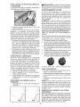
Determine
temperature
range
before oil change.
All oil must
service classification
C.
Be sure tractor
•
•
Oil will drain more freely when warm.
Catch oil in a suitable container.
•
Remove oil fill cap/dipstick.
Be careful
notto allow dirt to enter the engine when
changing oil.
Only use high quality detergent oil rated with
API service classification
SG-SL. Select the
Slide oil drain
•
hole (drain hole may be flush with or
protrude from engine block side wall).
Makesure backface of oil drain extension
to your
o -_0
-2_
TEMPERATURE
-1_
RANGE
_
ANTICIPATED
60
lo
BEFORE
80
_o
100
1o
4_
NEXT OIL CHANGE
oilviscchartl
e
oil drain
side wall.
•
Position a container
to catch oil directly
under front end of oil drain extension.
•
Slide a 1/2" (12 point) socket mounted
on an extension
onto oil drain plug.
•
Loosen plug while holding
extension firmly in place.
Drain oil into container.
o
40
under
Makesure bottom lip of oil drain extension
is lined up with bottom of oil drain hole.
o
32
extension
•
SAE VISCOSITY GRADES
30
(_
•
is flush with engine
LUBRiCATiON
0
is on level surface.
Drain Plug
ENGINE
-20
expected
meet API
•
Drain Hole
V-BELTS
Check V-belts for deterioration
and wear after
100 hours of operation and replace if necessary. The belts are not adjustable.
Replace
belts if they begin to slip from wear.
F
OIL
_CAUTION:
if engine has been operated
foran extended
period oftime immediately
prior to draining oil, oil will be hot.
Corrosion and dirt on the battery and terminals
can cause the battery to "leak" power.
1. Disconnect
BLACK
battery
cable first
then RED battery
cable and remove
battery from tractor.
2. Rinse the battery with plain water and dry.
3. Clean terminals and battery cable ends
with wire brush until bright.
4. Coat terminals with grease or petroleum
jelly.
5. Reinstall
battery
(See "REPLACING
BATTERY"
in the SERVICE
AND ADJUSTMENTS
section of this manual).
oil's SAE viscosity
grade according
expected
operating temperature.
ENGINE
the oil drain
After oil has drained completely,
reinstall
oil drain plug. Do not tighten more than
13 Ft-Lb's.
Refill engine with oil through oil fill dipstick
tube.
Pour slowly.
Do not overfill.
For
approximate
capacity
see "PRODUCT
SPEClFICATIONS"sectionofthismanual.
NOTE: Although multi-viscosity
oils (5W30,
10W30 etc.) improve starting in cold weather,
they will result in increased
oil consumption
when used above 32°R Check your engine
oil level more frequently
to avoid possible
engine damage from running low on oil.
Use gauge
on oil fill cap/dipstick
for
checking
level. Be sure dipstick cap is
tightened
securely for accurate reading.
Keep oil at"FULL' line on dipstick. Tighten
cap onto the tube securely when finished.
Change the oil after every 25 hours of operation or at least once a year if the tractor is
not used for 25 hours in one year.
Checkthe
crankcase oil level before starting
the engine and after each eight (8) hours of
operation. Tighten oil fill cap/dipstick securely
each time you check the oil level.
19
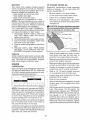
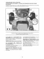
AiR FILTER
CLEANING
Your engine will not run properly using a dirty
air filter. Service air cleaner more often under
dusty conditions. See engine manual.
•
CLEAN AIR SCREEN
_ CAUTION: Avoid
able parts
•
Air screen must be kept free of dirt and chaff
to prevent engine damage from overheating. Clean with a wire brush or compressed
air to remove dirt and stubborn dried gum
fibers,
ENGINE COOLING
Clean engine, battery, seat, finish, etc.
of all foreign matter.
Clean debrisfrom
steering plate. Debris
can restrict cl utch/brake pedal shaft movement, causing belt slip and loss of drive.
all pinch points and mov-
Clutch/brake
/
SYSTEM
Debris may clog the engine's
air cooling
system. Remove blower housing and clean
area shown
to prevent
overheating
and
engine damage.
pedal
Clean
top
ii
Steering
PI_
Clean out chaff
and debris
Air Screer__
Steering System, Dash,
Fender and Mower Not Shown
•
•
PLUG(S)
Replace spark plug(s) atthe beginning ofeach
mowing season or after every 100 hours of
operation, whichever occurs first. Spark plug
type and gap setting are shown in "PRODUCT
SPECIFICATIONS"
section of this manual.
IN-LINE
FUEL
Pinch
Points
Keep finished surfaces and wheels
free of all gasoline, oil, etc.
Protect painted surfaces with automotive type wax.
We do not recommend
using a garden hose
or pressure
washer
to clean your tractor
unless
the engine
and transmission
are
covered to keep water out. Water in engine
or transmission
will shorten the useful life of
your tractor.
Use compressed
air or a leaf
blower to remove grass, leaves and trash
from tractor and mower.
MUFFLER
inspect and replace corroded muffler and
spark arrester (if equipped) as itcould create
a fire hazard and/or damage.
SPARK
[c o,o°
i
FILTER
The fuel filter should be replaced once each
season. If fuel filter becomes
clogged,
obstructing fuelflowto
carburetor, replacement
is required.
1. With engine cool, remove filter and plug
fuel line sections.
2. Place newfuel filter in position in fuel line
with arrow pointing towards carburetor.
3. Be sure there are no fuel line leaks and
clamps are properly positioned.
4. immediately
wipe up any spilled gasoline.
Clamp
2O
&
1.
2.
3.
4.
5.
6.
WARNING:
TO AVOID SERIOUS
ADJUSTMENTS:
iNJURY, BEFORE PERFORMING
ANY SERVICE OR
Depress clutch/brake pedal fully and set parking brake.
Place gearshift lever in neutral position.
Place attachment clutch in "DISENGAGED" position.
Turn ignition key to "STOP" and remove key.
Make sure the blades and all moving parts have completely stopped.
Disconnect spark plug wire from spark plug and place wire where it cannot come
in contact with plug.
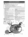
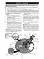
TO REMOVE MOWER
1. Place attachment
clutch in "DISENGAGED" position.
2. Lower attachment lift lever to its lowest
position.
3. Roll belt off engine pulley (M) and belt
keepers (G).
4. Remove cable (P) by depressing tab (L).
5. Remove clutch cable spring (Q) from
idler arm (R).
6. Disconnect front link (E) from mowerremove retainer spring and washer.
7. Go to either side of mower and disconnect mower suspension arm (A) from
chassis pin (B) and rear lift link (C) from
rear mower bracket (D)-remove retainer
springs and washers.
CAUTION: After rear lift links are disconnected, the attachment lift lever will be spring
loaded. Have a tight grip on lift lever when
changing position of the lever.
8. Slide mower out from under right side of
tractor.
IMPORTANT: If an attachment other than the
mower is to be mounted on the tractor, remove
the front link (E) and rear lift links (C) from
tractor and hook the clutch spring (Q) into
the cable guide on front edge of lower dash.
TO INSTALL MOWER
Be sure tractor is on level surface and engage
parking brake.
1. Lower attachment
lift lever to its lowest
position.
,_ CAUTION:
Lift lever is spring loaded.
Have a tight grip on lift lever, lower it slowly
and engage in lowest position.
NOTE:
Be sure mower
side suspension
arms (A) are pointing forward before sliding
mower under tractor.
2. Slide mower under tractor until it is cen-
tered under tractor.
21
3.
ATTACH
4.
ARMS (A) TO CHASSiS-Position
hole
in arm over pin (B) on outside of tractor
chassis and secure with retainer spring.
Repeat on opposite
side of tractor.
5.
SIDE SUSPENSION
7.
spring.
ATTACH
FRONT
left side of tractor.
LINK
Insert
assembly
through
front
front suspension
bracket
IMPORTANT:
Check belt for proper routing
in all mower pulley grooves.
11.Raise
attachment
lift lever to highest
position.
12. If necessary, adjust gauge wheels before
operating mower as shown in the Opera-
(E)-Work
from
rod end of link
hole
(F).
Insert end of link (E) into hole in front
mower
bracket
(H) and secure
with
washer and retainer spring (J).
8. Hook end of clutch cable spring (Q) into
hole in idler arm (R).
9. Push clutch cable housing guide (P) into
bracket,
10. Install belt onto engine pulley (M) and belt
keepers (G).
ATTACH REAR LIFT LINKS (C)-Lift rear
corner of mower and position slot in link
assembly
over pin (D) on rear mower
bracket
and secure
with washer
and
retainer
6.
MOWER
in tractor
22
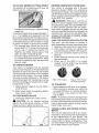
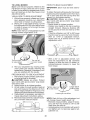
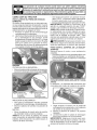
TO LEVEL
MOWER
Make sure tires are properly inflated to the
PSI shown on tires. If tires are over or under
inflated, it may affect the appearance
of your
lawn and lead you to think the mower is not
adjusted properly.
VISUAL
SIDE-TO-SIDE
FRONT-TO-BACK
IMPORTANT:
side.
ADJUSTMENT
Each full turn of adjustment
mower height about 3/16".
Deck must be level side-to-
To obtain the best cutting results, the mower
blades should be adjusted so the front tip is
1/8" to 3/8" lower than the rear tip when the
ower is in its highest position.
CAUTION:
Blades are sharp.
Protect
your hands with gloves and/or wrap blade
with heavy cloth.
• Raise mower to highest position.
• Position any blade so the tip is pointing
straight
forward.
Measure
distance
(B)
to the ground at front and rear tip of the
blade.
• If front tip of blade is not 1/8" to 3/8" lower
than the rear tip, go to the front of tractor.
• With an 11/16"
or adjustable
wrench,
loosen jam nut A several turns to clear
adjustment
nut B.
1. With all tires properly inflated and if your
lawn appears
unevenly
cut, determine
which side of mower is cutting lower.
2. With a 3/4" or ad ustable wrench, turn lift
link adjustment
nut (A) to the left to lower
LH side of mower, or, to the right to raise
LH side of mower.
NOTE:
change
ADJUSTMENT
nut will
B
Turn nut rig
to raise mower
3.
With a 3/4" or adjustable
wrench,
turn
front link adjustment
nut (B) clockwise
(tighten) to raise the front of mower, or,
counterclockwise
(loosen)
to lower the
front mower.
.. Turn nut left
........
.. . to lower mower
Test your adjustment
by mowing some
uncut grass and visually checking
the
appearance.
Readjust, if necessary, until
you are satisfied with the results.
PRECISION
SIDE-TO-SIDE
B
ADJUSTMENT
1. With all tires properly inflated, park tractor
on level ground or driveway.
Al_ CAUTION:
Blades are sharp.
Protect
your hands with gloves and/or wrap blade
with heavy cloth.
2. Raise mower to its highest position.
3. At both sides of mower, position blade at
side and measure the distance (A) from
bottom edge of blade to the ground. The
distance should bethe same on both sides.
4. If adjustment
is necessary,
see step 2 in
Visual Adjustment
instructions above.
5. Recheck measurements,
adjust if necessary until both sides are equal.
Tighten adjust nut
B to raise mower
........-
Loosen adjust
nut B to lower
mower
Loosen jam nut A first
NOTE: Each full turn of the adjustment
nut
will change mower height about 1/8".
• Recheck measurements,
adjust if necessary until front tip of blade is 1/8" to 3/8"
lower than the rear tip.
• Hold adjustment nut in position with wrench
and tighten jam nut securely against adjustment
nut.
23
TO REPLACE
MOWER
BLADE
DRIVE BELT
TO REPLACE
The mower blade drive belt may be replaced
without tools. Park the tractor on level surface.
Engage
parking
brake.
BELT REMOVAL
1. Remove mower. (See "TO REMOVE
MOWER" in this section of manual.)
2. Work belt off mandrel pulley and idler
pulleys,
3. Pull belt away from mower.
1.
2.
3.
DRIVE
BELT
Park the tractor on level surface.
Engage
parking brake.
For assistance,
there is
a belt installation
guide decal on bottom
side of left footrest.
BELT REMOVAL-
BELT
MOTION
-
1.
Remove mower (See "TO REMOVE
MOWER"
in this section of manual).
NOTE:
Observe
entire motion
drive belt
and position of all belt guides and keepers.
2. Remove belt from stationary
idler (A)
and clutching
idler (B).
3. Pull belt slack toward rear of tractor.
INSTALLATION-
Work belt around
mandrel
pulley and
idler pulleys
Make sure belt is in all pulley grooves
and inside all belt guides.
Install mower (See "To Install Mower" in
this section of this manual).
4.
5.
Remove belt upwards from transaxle
input pulley (D).
Remove belt downward
from engine
pulley (E).
Slide belt toward rear of tractor, off the
steering plate (F) and remove from tractor.
Mandrel
Pull_
Idler
;Pulleys
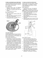
TO CHECK
BRAKE
If tractor requires more than five (5) feet to
stop at highest speed in highest gear on a
level, dry concrete
or paved surface,
then
brake must be serviced.
BELT INSTALLATION
You may also check brake by:
1. Park tractor on a level, dry concrete or
paved surface, depress
brake pedal all
the way down and engage parking brake.
2. Disengage
transmission
by placing
freewheel control in "transmission
disengaged" position.
Pull freewheel
out and into the slot and release
control
so it is
Install
2.
front, over the steering plate (F) and
above clutch brake pedal shaft (G).
Pull belt toward front of tractor and roll
3.
belt onto engine pulley (E).
Pull belt toward rear of tractor.
held in the disengaged
position.
The rear wheels must lock and skid when
you try to manually push the tractor forward.
If the rear wheels
rotate, then the brake
needs to be serviced.
Contact
a Sears or
other
qualified
service
4.
5.
center.
6.
24
-
1.
new belt from tractor
rear to
Care-
fully work belt down around transaxle
input pulley (D). Be sure belt is inside
the belt keeper.
Install belt through stationary
idler (A)
and clutching
idler (B).
Make sure belt is in all pulley grooves
and inside all belt guides and keepers.
Install mower (See "TO INSTALL
MOWER"
in this section of manual).
TRANSAXLE GEAR SHIFT LEVER NEUTRAL ADJUSTMENT
TO ADJUST STEERING
ALIGNMENT
The transaxle
If steering wheel crossbars are not horizontal
(left to right) when wheels are positioned
straightforward,
remove steering wheel and
reassemble
per instructions
in the Assembly
section of this manual.
should
be in neutral
when the
gear shift lever is in neutral (N) (lock gate)
position.
The adjustment
is preset at the
factory;
however, if adjustment
is needed,
proceed as follows:
1. Make sure transaxle
is in neutral (N).
NOTE: When the tractor rear wheels move
freely, the transaxle
is in neutral.
2. Loosen adjustment
bolt in front of the
right rear wheel.
3. Position the gear shift lever in the neutral
(N) position.
4. Tighten adjustment
bolt securely.
NOTE:
If additional clearance
is needed to
get to adjustment
bolt, move
height to the lowest position.
Gearshift
Lever
Adjustment
mower
FRONT
Your
WHEEL
new
tractor
WHEEL
TOE-IN/CAMBER
front
wheel
toe-in
and
camber is set at the factory and is normal.
The front wheel toe-in and camber are not
adjustable.
If damage has occurred to affect
the factory set front wheel toe-in or camber,
contact a qualified service center.
TO START ENGIN E WiTH WEAK BATTE RY
deck
_IbWARNING:
Lead-acid batteries generate
explosive
gases. Keep sparks, flame and
smoking materials awayfrom batteries. Always
wear eye protection when around batteries.
Bolt
If your battery is too weak to start the engi ne, it
should be recharged. (See "BATTERY" in the
MAINTENANCE
section of this manual).
If "jumper cables" are used for emergency
starting, follow this procedure:
Jtral
Lock Gate
TO REMOVE
IMPORTANT:
Your tractor is equipped with a
12 volt system. The other vehicle must also
be a 12 volt system. Do not use your tractor
battery to start other vehicles.
TO ATTACH JUMPER
CABLES-
WHEEL
1. Block up axle securely.
2. Remove axle cover, retaining ring and
washers to allow wheel removal (rear
wheels have a square key-Do not lose).
3. Repair tire and reassemble.
NOTE: On rear wheels only: align grooves in
rear wheel hub and axle. Insert square key.
4. Replace washers and snap retaining ring
securely in axle groove.
5. Replace axle cover.
NOTE: To seal tire punctures and prevent
flat tires due to slow leaks, purchase and
use tire sealant from Sears. Tire sealant also
prevents tire dry rot and corrosion.
Connectone
end ofthe
RED cabletothe
2.
POSITIVE (+) terminal of each battery(AB), taking care notto short against tractor
chassis.
Connect
one end of the BLACK cable
3.
to the NEGATIVE
(-) terminal (C) of fully
charged battery.
Connect
the other end of the BLACK
cable (D) to good chassis ground,
from fuel tank and battery.
TO REMOVE CABLES, REVERSE
1. BLACK cable firstfrom
chassis
Washers
Retaining
Rin(
Axle
Cover
Square
Key .......
(Rear Wheel Only)
1.
2.
25
ORDERand then
from the fully charged battery.
RED cable last from both batteries.
Weak or
Dead
Battery
"_-
away
Fully
Charged
Battery
REPLACING
BATTERY
TO REMOVE
n_asWARNING: Do not short battery termiby allowing a wrench or any other object
to contact both terminals at the same time.
Before connecting battery, remove metal
bracelets, wristwatch bands, rings, etc.
Positive terminal must be connected first to
prevent sparking from accidental grounding.
1. Lift seat pan to raised position.
2. Disconnect BLACK battery cable first
then RED battery cable and carefully
remove battery from tractor.
3. Install new battery with terminals in same
position as old battery.
4. First connect RED battery cable to positive (+) terminal with hex bolt and keps
nut as shown. Tighten securely. Slide
terminal cover over terminal
5. Connect BLACK grounding
cable to
negative (-) terminal with remaining hex
bolt and keps nut. Tighten securely.
HOOD
& GRILL
ASSEMBLY
1.
Raise
hood.
2.
3.
Unsnap headlight wire connector.
Stand in front of tractor. Grasp hood at
sides, tilt toward engine and lift off of
tractor.
4.
When replacing hood, be sure to reconnect the headlight wire connector.
Headlight
Wire
Connector
Seat Pan
ENGINE
Terminal
Cover
TO ADJUST
Nut
Negative
(Black)
Bolt
TO ADJUST
HEADLIGHT
AND
BULB
TO ADJUST
CONTROL
CARBURETOR
Your carburetor has been preset atthe factory
and adjustment
should not be necessary.
However, minor adjustment
may be required
to compensate
for differences
in fuel, temperature, altitude or load. If the engine does
need adjustment,
see engine manual.
RELAYS
Loose or damaged
wiring may cause your
tractor to run poorly, stop running, or prevent
it from starting.
• Check wiring. See the electrical
wiring
diagram in the Repair Parts manual.
TO REPLACE
CHOKE
The choke control has been preset at
the factory and adjustment should not be
necessary. If adjustment is necessary, see
engine manual.
1. Raise hood.
2. Remove bulb holder from the hole in the
backside of the grill.
3. Replace bulb in holder and install bulb
holder securely back into the hole in the
backside of the grill.
4. Close hood.
INTERLOCKS
CONTROL
The throttle control has been preset at
the factory and adjustment should not be
necessary Check adjustment as described
below before loosening cable. If adjustment
is necessary, see engine manual.
Positive
(Red)
TO REPLACE
THROTTLE
FUSE
Replace with 20 amp automotive-type plugin fuse. The fuse holder is located behind
the dash.
26
Immediately
prepare your tractor for storage
at the end of the season or if the tractor will
• Empty the fuel tank by starting the engine
and letting it run until the fuel lines and
carburetor
are empty.
• Never use engine or carburetor
cleaner
products
in the fuel tank or permanent
damage may occur.
• Use fresh fuel next season.
not be used for 30 days or more.
_,WARNING:
Never
store the tractor
with
gasoline in the tank inside a building where
fumes may reach an open flame or spark.
Allow the engine to cool before storing in
any enclosure.
NOTE:
Fuel stabilizer
is an acceptable
alternative
in minimizing
the formation
of
fuel gum deposits
during
storage.
Add
stabilizer to gasoline in fuel tank or storage
container. Always follow the mix ratio found
on stabilizer
container. Run engine at least
10 minutes after adding stabilizer to allow
the stabilizer to reach the carburetor. Do not
TRACTOR
When tractor is to be stored for a period
of time, clean it thoroughly,
remove all dirt,
grease, leaves, etc. Store in a clean, dry area.
1. Clean entiretractor
(See"CLEANING"
in
the Maintenance
section of this manual).
2. Inspectand replacebelts, ifnecessary (See
belt replacementinstructions
inthe Service
and Adjustments
section ofthis manual).
3. Lubricate
as shown in the Maintenance
section of this manual.
4. Be sure that all nuts, bolts and screws
are securely fastened.
Inspect moving
parts for damage,
breakage
and wear.
Replace if necessary.
5. Touch up all rusted or chipped
paint
surfaces;
sand lightly before painting.
empty the gas tank and carburetor
fuel stabilizer.
ENGINE OIL
Drain oil (with engine warm) and replace
with clean engine oil. (See "ENGINE"
in the
Maintenance
section of this manual).
CYLINDER(S)
1.
2.
3.
BATTERY
4.
• Fully charge the battery for storage.
• After a period of time in storage,
battery
may require recharging.
• To help prevent corrosion and power leakage during long periods of storage, battery
cables should be disconnected
and bat-
Remove spark plug(s).
Pour one ounce ofoil through spark plug
hole(s) into cylinder(s).
Turn ignition key to start position for a
few seconds to distribute oil.
Replace
with new spark
plug(s).
OTHER
• Do not store gasoline
another.
from one season
to
• Replace
your gasoline
can if your can
starts to rust. Rust and/or dirt in your
gasoline will cause problems.
• If possible, store your tractor indoors and
cover itto give protection from dust and dirt.
• Cover your tractor with a suitable protective cover that does not retain moisture.
tery cleaned thoroughly
(see "TO CLEAN
BATTERY
AND TERMINALS"
in the
Maintenance
section of this manual).
• After cleaning, leave cables disconnected
and place cables where they cannot come
in contact with battery terminals.
• If battery
is removed
from tractor
for
storage, do not store battery directly on
concrete or damp surfaces.
Do not use plastic. Plastic cannot breathe
which allows condensation
to form and
will cause your tractor to rust.
IMPORTANT:
Never cover tractor
while
engine and exhaust areas are still warm.
ENGINE
FUEL
if using
SYSTEM
IMPORTANT:
It is important to prevent gum
deposits from forming in essential fuel system parts such as carburetor,
fuel hose, or
tank during storage. Also, alcohol blended
fuels (called gasohol
or using ethanol
or
methanol)
can attract moisture which leads
to separation
and formation
of acids during
storage.
Acidic gas can damage
the fuel
system of an engine while in storage.
27
TROUBLESHOOTING
See appropriate
CHART:
section in manual
PROBLEM
Will
not start
Hard to start
Engine
will not
turn over
unless directed
CAUSE
to Sears service
center
CORRECTION
1
Out of fuel.
1
Fill fuel tank.
2
Engine not "CHOKED" properly.
2
See "TO START ENGINE" in
Operation section.
3
Engineflooded.
3
Wait several minutes before
attempting to start.
4
Bad spark plug.
4
Replace spark plug.
5
Dirty air filter.
5
Clean/replace air filter.
6
Dirty fuel filter.
6
Replace fuel filter.
7
Water in fuel.
7
Empty fuel tank and carburetor,
refill tank with fresh gasoline and
replace fuel filter.
8
Loose or damaged wiring.
8
Check all wiring.
9
Carburetor out of adjustment.
9
See "To Adjust Carburetor" in
Service and Adjustments section.
10
Engine valves
1
Dirty air filter.
1
Clean/replace air filter.
2
Bad spark plug.
2
Replace spark plug.
3
Weak or dead battery.
3
Recharge or replace battery.
4
Dirty fuel filter.
4
Replace fuel filter.
5
Stale or dirty fuel.
5
Empty fuel tank and refill tank with
fresh, clean gasoline.
6
Loose or damaged wiring.
6
Check all wiring.
7
Carburetor out of adjustment.
7
See "To Adjust Carburetor" in
Service and Adjustments section.
8
Engine valves
8
Contact a Sears or other qualified
service center.
1
Clutch/brake pedal not depressed.
1
Depress clutch/brake pedal.
2
Attachment clutch is engaged.
2
Disengage attachment clutch.
3
Weak or dead battery.
3
Recharge or replace battery.
4
Blown fuse.
4
Replace fuse.
5
Corroded battery terminals.
5
Clean battery terminals.
6
Loose or damaged wiring.
6
Check all wiring.
7
Faulty ignition switch.
7
Check/replace ignition switch.
8
Faulty solenoid or starter.
8
Check/replace solenoid or starter.
9
Faulty operator presence
switch(es).
9
Contact a Sears or other qualified
service center.
out of adjustment.
out of adjustment.
28
10 Contact a Sears or other qualified
service center.
TROUBLESHOOTING
See appropriate
CHART:
section
unless directed
CAUSE
PROBLEM
Engine clicks
will not start
in manual
but
Loss of power
Excessive vibration
to Sears service center
CORRECTION
1
Weak or dead battery.
1
Recharge or replace battery.
2
Corroded battery terminals.
2
Clean battery terminals.
3
Loose or damaged wiring.
3
Check all wiring.
4
Faulty solenoid or starter.
4
Check/replace solenoid or starter.
1
Cutting too much grass/too fast.
1
Raise cutting height/reduce
speed.
2
Throttle in "CHOKE" position.
2
Adjust throttle control.
3
Build-up of grass, leaves and
trash under mower.
3
Clean underside of mower
housing.
4
Dirty air filter.
4
Clean/replace air filter.
5
Low oil level/dirty oil.
5
Check oil level/change oil.
6
Faulty spark plug.
6
Clean and regap or change spark
plug.
7
Dirty fuel filter.
7
Replace fuel filter.
8
Stale or dirty fuel.
8
Empty fuel tank and refill tank with
fresh, clean gasoline.
9
Water in fuel.
9
Empty fuel tank and carburetor,
refill tank with fresh gasoline and
replace fuel filter.
10
Spark plug wire loose.
10 Connect and tighten spark plug
wire.
11
Dirty engine air screen/fins.
11 Clean engine air screen/fins.
12
Dirty/clogged muffler.
12 Clean/replace muffler.
13
Loose or damaged wiring.
13 Check all wiring.
14
Carburetor out of adjustment.
14 See "To Adjust Carburetor" in
Service and Adjustments section.
15
Engine valves
15 Contact a Sears or other qualified
service center.
out of adjustment.
1
Worn, bent or loose blade.
1
Replace blade. Tighten blade bolt
2
Bent blade mandrel.
2
Contact a Sears or other
qualified service center.
Engine continues tc
run when operator
leaves seat with
attachment
clutch
engaged
3
Loose/damaged
part(s).
1
Faulty operator-safety
control system,
29
presence
3
Tighten loose part(s).
Replace damaged parts.
1
Check wiring, switches and
connections. If not corrected,
contact a Sears or other
TROUBLESHOOTING
See appropriate
CHART:
section
PROBLEM
in manual
unless directed
CAUSE
to Sears service
center
CORRECTION
Poor cut-uneven
1
Worn, bent or loose blade.
1
Replace blade. Tighten blade bolt.
cutting
2
Mower deck not level.
2
Level mower deck.
3
Buildup of grass, leaves, and
trash under mower.
3
Clean underside of mower
housing.
4
Bent blade mandrel.
4
Contact a Sears or other
qualified service center.
5
Clogged mower deck vent from
build-up of grass, leaves, and
trash around mandrels.
5
Clean around mandrels
open vent holes.
1
Obstruction in clutch mechanism.
1
Remove obstruction.
2
Worn/damaged
3
Frozen idler pulley.
3
Replace idler pulley.
4
Frozen blade mandrel.
4
Contact a Sears or other
qualified service center.
1
Engine speed too slow.
1
Place throttle control in "FAST"
position.
2
Travel speed too fast.
2
Shift to slower speed.
3
Wet grass.
3
Allow grass to dry before mowing.
4
Mower
deck not level.
4
Level mower deck.
5
Low/uneven tire air pressure.
5
Check tires for proper PSI.
6
Worn, bent or loose blade.
6
Replace/sharpen blade. Tighten
blade bolt.
7
Buildup of grass, leaves and
trash under mower.
7
Clean underside of mower
housing.
8
Mower drive belt worn.
8
Replace mower drive belt.
9
Blades improperly installed.
9
Reinstall blades sharp edge down.
10
Improper blades used.
11
Clogged mower deck vent holes 11 Clean around mandrels to
from buildup of grass, leaves, and
open vent holes.
trash around mandrels.
Mower blades
not rotate
will
Poor grass
discharge
Headlight(s)
not
working
(if so equipped)
Battery
charge
will not
mower drive belt. 2
to
Replace mower drive belt.
10 Replace with blades listed in
this manual.
1
Light switch is "OFF".
1
Turn light switch "ON".
2
Bulb(s) or lamp(s) burned out.
2
Replace bulb(s) or lamp(s).
3
Faulty light switch.
3
Check/replace light switch.
4
Loose or damaged wiring.
4
Check wiring and connections.
5
Blown fuse.
5
Replace fuse.
1
Bad battery cell(s).
1
Replace battery.
2
Poor cable connections.
2
Check/clean all connections.
3
Faulty regulator (if so equipped).
3
Replace regulator.
4
Faulty alternator.
4
Replace alternator.
3O
TROUBLESHOOTING
See appropriate
CHART:
section
in manual
unless directed to Sears service
center
PROBLEM
CAUSE
Loss of drive
Debris on steering plate (if
equipped).
1
See"CLEANING" in the
maintenance section.
2
Motion drive belt worn, damaged,
or broken.
2
Replace motion drive belt.
3
Axle key missing.
3
Install axle key at rear wheel. See
"TO REMOVE WHEEL" in the
Service and Adjustments section.
1
Engine
throttle
control
not set
between half and full speed (fast)
position
before stopping
engine,
1
Move throttlecontrol
between
half and full speed (fast) position
before stopping engine.
1
Reverse operation system (ROS)
is not "ON" while mower or other
attachment is engaged.
1
Turn ignition key to ROS "ON"
position. See Operation section.
Engine
"backfires"
when turning
engine
"OFF"
Engine dies when
tractor is shifted
into reverse
Mower
will
not
CORRECTION
Bagger or optional rear
discharge deflector is not
installed correctly.
operate
Check bagger or optional rear
discharge deflector for proper
installation
NEED HORE HELP?
Ybu'U_ fir@ the
answer
and
re.ore on _anage_yhOmeoCO_
o Find this and aLLyour other product manuals online.
o Get answers from our team of home experts.
o Get a personalized maintenance
o Find information
plan for your home.
and tools to help with home projects.
brought to you by Sears
'[[
31
_ for
free!
SUGGESTED
GUIDE FOR SIGHTING
SLOPES
FOR SAFE OPERATION
ONLY RIDE UP AND DOWN HILL,
NOT ACROSS HILL
15 DEGREES MAX.
_
down the face of slopes, never across the face. Do not mow
ARNING:
To avoid
serious
injury,
operate
your tractor
and
slopes
greater
than 15
degrees.
Make
turns gradually
to up
prevent
tipping or loss of control. Exercise extreme caution when
changing direction on slopes.
1. Fold this page along dotted line indicated above.
2. Hold page before you so that its left edge is vertically parallel to a tree
trunk or ether upright structure.
3. Sight across the fold in the direction of hill slope you want to measure.
4. Compare the angle of the fold with the slope of the hill.
Garanfia..........................................................
33 ProgramadeMantenimiento
..........................
48
ReglasdeSeguridad......................................
34 Servicioy Ajustes...........................................
52
.............................................
58
Especificaciones
delProducto
........................
37 Almacenamiento
de Problemas...........................
59
Montaje/PreOperaci6n
...................................
39 Identificaci6n
Operaci6n
.......................................................
42 ServicioSears..................................
Contratapa
Mantenimiento
................................................
48
Garantia Para Equipos Tractores Craftsman:
Tractores Cortacesped, Tractores De Jardin, Carritos Con Radio De Giro Cero
GARANTiA
COMPLETA
POR DOS AltOS
DE CRAFTSMAN
Si alguna de las partes de desgaste de este equipo tractor falla debido a un defecto de material o mano
de obra DENTRO DE LOS DOS ANOS posteriores a la fecha de compra, visite www.craftsman.
corn o Ilame al 1-800-659-5917 para solicitar la reparaci6n gratuita en nuestras instalaciones.
El bastidor y el eje delantero se repararan sin cargo por cinco ahos a partir de la fecha de compra si
tienen defectos de material o mano de obra.
En todos los casos, si la reparaci6n
mismo modelo o uno equivalente.
es imposible,
el equipo tractor ser_t sustituido sin cargo con el
La bateria se sustituira sin cargo durante 90 dias a partir de la fecha de compra si tiene defectos de
material o mano de obra (nuestras pruebas demuestran que no retiene la carga).
Esta garantia sera nula si este producto se utiliza alguna vez para brindar servicios comerciales
se alquila a otra persona.
Esta garantia
cubre 0NICAMENTE
cobertura
de garantia
NO incluye:
•
•
•
•
•
•
•
•
defectos
de material
y mano
de obra.
o si
La
Componentes de desgaste que se puedan desgastar por el uso normal dentro del periodo de
garanfia, incluso (pero sin limitarse a ello) hojas, bujias, filtros de aire, correas y filtros de aceite.
Servicios de mantenimiento estandar, cambios de aceite o afinaciones.
Reemplazo o reparaci6n de neumaticos por pinchazos causados por objetos externos como
clavos, espinas, tocones o vidrios.
Reemplazo o reparaci6n de neumaticos o ruedas por desgaste normal, accidentes o por
operaci6n o mantenimiento incorrectos.
Reparaciones necesarias por abuso del operador, incluso (pero sin limitarse a ello) dahos
causados pot remolcar objetos que superen la capacidad del equipo tractor, chocar contra
objetos que doblen el bastidor o el cig_eSal o sobrepasar la velocidad del motor.
Reparaciones necesarias por negligencia del operador, incluso (pero sin limitarse a ello)
daSos electricos y mecanicos causados por el almacenamiento incorrecto, por no usar el
grado y la cantidad correctos de aceite de motor, pot no mantener del muelle libre de residuos
inflamables o por no mantener el equipo tractor de acuerdo con las instrucciones que contiene
el manual del operador.
Limpieza o reparaciones del motor (sistema de combustible) cuando se determina que se us6
combustible contaminado y oxidado (sarro). En general, el combustible debe usarse dentro de
los 30 dias posteriores a su compra.
Deterioro y desgaste normal de los acabados exteriores o sustituci6n de r6tulos de productos.
Esta garantia le otorga derechos legales especificos,
que vadan de un estado a otto.
Sears
Brands
Management
Corporation,
y usted tambi6n puede tenet otros derechos
Hoffman
33
Estates,
IL 60179
_PELIGRO:
Esta Maquina cortadora es capaz de amputar las manosy
objetos, si no se observan las instrucciones de seguridad siguientes
lesiones graves o la muerte.
,
los pies y de lanzar
se pueden producir
No maneje la maquina si no tiene la trampa
para c6sped completa, la canaleta de descarga
u otros dispositivos de seguridad en su lugar
yen funcionamiento.
, Ralentizar antes de girar.
, Nunca dejar una maquina encendida sin vigilancia. Apagar siempre las cuchillas, poner el
freno de estacionamiento,
parar el motor, y
quitar las Ilaves antes de bajar.
, Desenganche
las hojas cuando no est6
cortando cesped. Apague el motor y espere
hasta que todas las partes se detengan por
completo antes de limpiar la maquina, retirar
la trampa para c6sped o destapar la canaleta
de descarga.
, Hacer funcionar la mAquina s61o con la luz del
dia o luz artificial buena.
, No hacer funcionar la maquina estando bajo
los efectos de alcohol o droga.
, Poner atenci6n al trafico cuando se opera
cerca de calles o se cruzan.
, Poner la maxima atenci6n al cargar o descargar la maquina en una caravana o cami6n.
, Llevar siempre gafas de protecci6n cuando se
hace funcionar la mAquina.
, Los datos indican que los operadores a partir
de los 60 aflos estan afectados por un gran
porcentaje de heridas relativas a la conducci6n
del cortacesped. Estos operadores tendrian
que evaluar su habilidad de hacer funcionar
el cortac6sped de modo Io bastante seguro
para proteger a si mismos y a otras personas
de heridas graves.
, Seguir las recomendaciones
del fabricante
para los pesos y contrapesos de las ruedas.
, Mantener la mAquina libre de hierba, hojas
u otros escombros
que pueden tocar el
tubo de escape / partes del motor calientes
y quemarse. No permitir que el puente del
cortacesped cargue hojas u otros residuos
que pueden causar acumulaciones.
Limpiar
toda salpicadura de aceite o carburante antes
de hacer operaciones
sobre la maquina o
guardarla. Dejarla enfriar antes de guardarla.
II. FUNCIONAMIENTO
EN PENDIENTES
Las pendientes son el mayor factor de accidentes relativos a la p6rdida de control y vuelco,
que pueden causar severas heridas o muerte.
El funcionamiento
en pendientes requiere una
atenci6n extra. Si no es posible hacer marcha
atras en una pendiente o si te sientes incomodo,
no la cortes.
, Cortar hacia arriba y abajo de una pendiente,
no de modo horizontal.
, Poner atenciones a los hoyos, las raices, los
bultos, las piedras u otros objetos escondidos.
El terreno irregular puede volcar la maquina.
La hierba alta puede esconder obstaculos.
_DVERTENCIA:
Siempre desconecte el alambre de la bujia y p6ngalo donde no pueda entrar
en contacto con la bujia, para evitar el arranque
por accidente, durante la preparaci6n, el transporte, el ajuste o cuando se hacen reparaciones.
_DVERTENCIA:
No avance cuesta abajo a punto muerto ya que podria perder et control det tractor.
,_ADVERTENClA:
Remolque solamente los
accesorios recomendados
y conformes alas
caracteristicas indicadas por el fabricante de su
tractor. Tenga cuidado y prudencia al utilizar el
tractor. Cuando se encuentre en un declive, oper
utilizando exclusivamente la velocidad mas baja.
En caso de un declive una carga excesiva podda
resultar peligrosa.
Los neumaticos
pueden
perder la tracci6n con el suelo y hacerle perder
el control de su tractor.
_DVERTENClA:
El tubo de escape del motor,
algunos de sus constituyentes y algunos componentes del vehiculo contienen o desprenden
productos quimicos conocidos en el Estado de
California como causa de cancer y defectos al
nacimiento u otros daflos reproductivos.
_ADVERTENCIA:
Los bornes, terminales y accesorios relativos de la bateria contienen plomo
o compuestos de plomo, productos quimicos
conocidos en el Estado de California como causa
de cancer y defectos al nacimiento u otros daflos
reproductivos.
Lavar las manos despues de
rnanipularlos.
I. FUNCIONAiVllENTO
GENERAL
, Leer, entendery seguirtodas las instrucciones
sobre la maquina yen el manual antes de
empezar.
, No poner las manos o los pies cerca de partes
giratorias o debajo de la maquina, mantener
siempre limpia la abertura de descarga.
, Permitir el funcionamiento de la mAquina s61o
a adultos que tengan familiaridad
con las
instrucciones.
, Limpiar el Area de objetos como piedras,
juguetes, cables, etc. que pueden ser recogidos y disparados con las cuchillas.
, Asegurarse de que el Area este libre de otras
personas antes de ponerla en march& Parar
la maquina si alguien entra en el Area.
, Nunca Ilevar pasajeros.
, No cortar marcha atras al no ser absolutamente necesario. Mirar siempre abajo y
delante mientras se procede atras.
, Nunca dirigir el material descargado hacia nadie. Evitar descargar material contra paredes
u obstrucciones.
El material podria rebotar
hacia el operador. Parar las cuchillas cuando
se pasan superficies de grava.
34
, Escogeruna velocidadde marchabaja de
modoquenoseanecesariopararseo cambiar
estandoen unapendiente.
, Nocortarlahierbamojada.Lasruedaspueden
perdertracci6n.
Ponersiempreuna marchacuandose esta
enpendientes.
Noponeren puntomuertoe ir
cuestaabajo.
, Evitararrancar,pararseo giraren unapendiente.Si lasruedaspierdentracci6n,desconectar las cuchillasy procederdespaciocuesta
abajoenla pendiente.
, Mantenertodo los movimientosen las pendienteslentosy gradual.No hacercambios
repentinosde velocidado direcci6n,ya que
puedencausarel escapede la maquina.
, Ponerlam_txima
atenci6ncuandolam_quina
funcionacon captadoresde hierbau otros
dispositivosenganchados;
puedenafectarla
estabilidadde la maquina.Nousaren pendientesempinados.
, Nointentarestabilizarla maquinaponiendoel
pieen elterreno.
, Nocortarcercade bajadas,cunetasy orillas.
Lasm&quinapuedevolcarseimprovisamente
si unaruedaest&enel bordeo se hunde.
III. NINOS
Si el operador no pone atenci6n a la presencia
de los nifios pueden ocurrir accidentes tragicos.
Los niflos a menudo estan atraidos por la maquinay las actividad de cortar. No dar por hecho
de que los nifios se queden adonde estaban la
t31timavez que los vistes.
, Mantener los nifios fuera del area de corte y
vigilados por un adulto responsable que no sea
el operador.
, Estar alerta y apagar la m_tquina si un nifios
entra en el _rea.
, Antes y durante la marcha atras, mirar adelante
y abajo para ver si hay nifios pequefios.
, Nunca Ilevar nifios, incluso si hay las cuchillas
apagadas. Podrian caer y herirse seriamente
o interferir con el funcionamiento seguro de la
maquina, los nifios que se han Ilevado precedentemente pueden aparecer de pronto en el
_trea de corte pot otto paseo y set atropellados
o tumbados por la maquina.
, Nunca dejar que los nifios manipulen
la
maquina.
, Tenet el m&ximo cuidado cuando se acerca a
cantos ciegos, arbustos, arboles u otros objetos que pueden impedir la vista de nifios.
IV. REIVIOLQUE
, Remolcar s61o con una m_quina que tenga un
gancho disefiado para remolcar. Enganchar el
equipo o remolcar s61o en el punto dispuesto
al efecto.
, Seguir las recomendaciones del productor con
respecto a los limites del equipo por remolcar
y el remolque en pendientes.
,
Nunca permitir que nifios u otras personas
est6n dentro del equipo por remolcar.
, En pendientes, el peso del equipo remolcado
puede causar la p6rdida de tracci6n y la p6rdida de control.
, Viajar despacio y dejar m&s distancia para
frenar.
V. SERVlClO
MANIPULACION SEGURA DE LA GASOLINA
Para evitar heridas personales o dafios alas
cosas, poner el maximo cuidado a la hora de manipular la gasolina. La gasolina es extremamente
inflamable y los vapores son explosivos.
, Apagar todos los cigarrillos, cigarros, pipas y
otras fuentes de ignici6n.
, Usar s61o contenedores para gasolina aprobados.
, Nunca quitar el tap6n de la gasolina o afiadir
carburante con el motor en marcha, dejar
enfriar el motor antes del abastecimiento de
la gasolina.
, Nunca abastecer la maquina al interior de un
local.
, Nunca guardar la m&quina o el contenedor
del carburante donde haya una llama abierta,
chispas o una luz piloto como un calentador
de agua u otros dispositivos.
, Nunca Ilenar los contenedores al interior de
un vehiculo o en una caravana o cami6n
recubiertos con un forro de pl&stico. Colocar
siempre los contenedores en el terreno lejos
del vehiculo cuando se esta Ilenando.
, Quitar el equipo de gas del cami6n o caravana
y abastecerlo en el terreno. Si no es posible,
abastecer dicho equipo con un contenedor portatil, mas bien que de un surtidor de gasolina.
, Mantener la boquilla a contacto del borde
del dep6sito de carburante o la abertura del
contenedor
durante toda la operaci6n de
abastecimiento. No utilizar un dispositivo con
boquilla cerrada-abierta.
, Si se vierte carburante sobre la ropa, cambiarse la ropa inmediatamente.
, Nunca Ilenar el dep6sito mas de Io debido.
Volver a colocar el tap6n del gas y cerrar de
modo firme.
OPERACIONES
,
,
,
35
DE SERVICIO GENERALES
Nunca hacer funcionar la m&quina en un _trea
cerrada.
Mantener todas las tuercas y pernos apretados
para asegurarse de que trabaja en condiciones
seguras.
Nunca modificar los dispositivos de seguridad.
Controlar su correcto funcionamiento regularmente.
, Mantenerla maquinalibre de hierba,hojas
u otros residuosacumulados.Limpiarlas
salpicaduras
de aceiteo carburantey quitar
cualquiercosamojadaconcarburante.Dejar
quela maquinase enfrieantesde guardarla.
, Sisegolpeaunobjetoajeno,hayquepararse
e inspeccionar
lam_quina.Reparar,si esnecesario,antesdevolvera poneren marcha.
, NuncahacerningOnajusteo reparaci6ncon
el motorenfunci6n.
, Verifiqueloscomponentes
de latrampapara
c6spedylacanaletadedescargaconfrecuenciay sustituyacon repuestosrecomendados
porel fabricantecuandoseanecesario.
, Las cuchillasdel cortac6spedson afiladas.
Envolverlacuchilla,ponerseguantesy poner
la m_ximaatenci6ncuandose hacenoperacionesenelias.
, Controlarelfuncionamiento
delfrenofrecuentemente.Ajustary hacerlas operacionesde
mantenimiento
cuandoesoseanecesario.
, Mantenerysustituirlasetiquetasdeseguridad
e instrucci6n,cuandoseanecesario.
, Asegurarsedequeelareaest6libredeotras
personasantesdeponerlaenmarcha,parala
m_quinasi alguienentraen el &tea.
, NuncaIlevarpasajeros.
, Nocortarmarchaatr_ts
alnosetabsolutamente
necesario.Mirar siempre abajo y delante
mientrasse procedeatras.
, NuncaIlevarnifios,inclusosi haylascuchillas
apagadas.Podriancaery herirseseriamente
o interferirconel funcionamiento
segurodela
m&quina,los nifiosquese hanIlevadoprecedentemente
puedenaparecerdeprontoenel
_treadecorteporottopaseoysetatropellados
o tumbadosporlamaquina.
, Mantenerlos nifiosfueradel_reade cortey
vigiladosporunadultoresponsable
quenosea
el operador.
, Estaralertay apagarla maquinasi un nifios
entraenel _.rea.
, Antesydurantelamarchaatras,miraradelante
y abajoparaver si hayniflospequeflos.
, Cortarhaciaarribay abajode unapendiente
(15° Max),node modohorizontal.
, Escogeruna velocidadde marchabaja de
modoquenoseanecesariopararseocambiar
estandoenunapendiente.
, Evitararrancar,pararseo giraren unapendiente.Si lasruedaspierdentracci6n,desconectar las cuchillasy procederdespaciocuesta
abajoen lapendiente.
, Si la maquinase para mientrasva cuesta
arriba,desconectarlas cuchillas,poner la
marchaatrasy ir haciaatrasdespacio.
, Nogirarestandoenpendientessi noes necesario,y luegogirardespacioy gradualmente
cuestaabajo,si esposible.
36
ESPECIFICACIONESDEL PRODUCTO
Capacidady Tipo
degasolina:
TipodeAceite:
(API-SG-SL)
Capacidadde
Aceite:
Bujia:
Velocidad
de
Recorrido (MPH):
ACUERDOS
DE PROTECClON
LA REPARACI()N
1.5Galones(5,68L)
RegularSinPlomo
SAE30(Sobre32°F/0°C)
SAE5W30
(Debajo32°F/0°0)
Congratulaciones
por su buena compra. Su
nuevo producto Craftsman® estA disefiado y
fabricado para funcionar de modo fiable por
muchos afios. Pero como todos los productos,
puede necesitar alguna reparaci6n de tanto en
tanto. En este caso tener un Acuerdo de Protecci6n para la Reparaci6n puede hacerles ahorrar
dinero y fastidios.
Compre ahora un Acuerdo de Protecci6n para
48oz.
ChampionRCl2YC
(Abertura:.030")
Delante:
0-5.2
la Reparaci6n y prot6gese de molestias y gastos
inesperados.
Marcha Atr_ts:
0-2.9
Un Acuerdo incluye los puntos siguientes:
Sistema de Carga: 3 Amps Bateria
5 Amps Luces Delanteras
Bateda:
Torsi6n del Perno
de la Cuchilla:
PARA
Amp/Hr:
Min. CCA:
Case Size:
28
230
U1R
45-55 Ft. Lbs.
FELIClTAClONES por la compra de su tractor. Ha
sido disefiado, planificado y fabricado para darle la
mejor confiabilidad y el mejor rendimiento posible.
,
Siga un programa regular de mantenimiento,
cuidado y uso de su tractor.
,
Siga las instrucciones descritas en las secciones "Mantenimiento"
y 'Almacenamiento"
de este Manual del Duefio.
Servicio
ilimitado sin cargo alguno para
las partes y la mano de obra sobre todas las
reparaciones garantizadas.
,
Sustitucion
garantizado
del producto si su producto
no puede ser arreglado.
Cuando se ha comprado el Acuerdo, basta con
una Ilamada telef6nica para programar el servicio.
Puede Ilamar cuando quiera, dia y noche o fijar
en linea una cita para obtener el servicio. Sears
tiene m&s de 12.000 especialistas profesionales
en la reparaci6n, que tienen acceso a mas de 4.5
millones de partes y accesorios de calidad.
DEL CLIENTE
Lea y observe las reglas de seguridad.
,
Ayuda rapida pot telefonosoporte telef6nico por parte de un representante Sears sobre
productos que requieren un arreglo en casa, y
ademas una programaci6n sobre los arreglos
mas convenientes.
Haga el favor de leer y de guardar este manual.
Estas instruc-ciones le permitiran montar y mantener su unidad en forma adecuada. Siempre
observe las "REGLAS DE SEGURIDAD."
RESPONSABILIDADES
Servicio experto de nuestros !2.000 especialistas profesionales en la reparaci6n.
Descuento del 10% sobre el precio corriente
del servicio y de las partes relativas al servicio
no cubiertas por el acuerdo; tambien el 10%
menos sobre el precio corriente de un control
de mantenimiento preventivo.
En el caso de que se encuentre con cualquier
problema que no pueda solucionar facilmente,
haga el favor de ponerse en contacto con un
centro de servicio Sears o con un otto centro de
servicio cualificado. Cuenta con representantes
bien capacitados y competentes y con las herramientas adecuadas para darle servicio o para
reparar este tractor.
,
,
Este es el tipo de profesionalidad con que puede
contar para ayudar a alargar la vida del producto que acaba de comprar, por muchos afios.
iCompre hoy su Acuerdo de Protecci6n para la
Reparaci6n!
,_ADVERTENOIA:
Este tractor viene equipado
con un motor de combusti6n interna y no se debe
usar sobre, o cerca, de un terreno no desarrollado
cubierto de bosques, de arbustos o de c6sped,
o menos que el sistema de escape del motor
venga equipado con un amortiguador de chispas
que cumpla con las leyes locales o estatales (si
existen). Si se usa un amortiguador de chispas,
el operador debe mantenerlo en condiciones de
trabajo eficientes.
Se aplican
algunas
limitaciones
y exclu=
siones. Para conocer los precios y tener mas
Informacion,
Ilame al 1-800-827-6655.
SERVlClO
DE INSTALAClON
SEARS
Para la instalacidn profesional Sears de aparatos de casa, puertas de garaje, calentadores de
agua y otros importantes arficulos para la casa,
en U.S.A Ilamar a
1-800-4-MY-HOME®
En el estado de California, la ley exige Io anterior
(Secci6n 4442 del "California Public Resources
Code"). Otros estados pueden contar con otras
leyes parecidas. Las leyes federales se aplican
en la tierras federales. Su centro de Servicio mas
cercano tiene disponible amortiguadores de chispas para el silenciador. (Vea la secci6n de Partes
de Repuesto en el manual Ingl6s del dueflo.)
37
Contenedor
Volante
i
i
i
de direcci6n
\
l
,f'f
1/4 x 20 x 1.25"
Perno cabeza redondo
Inserto del
volante de
direcci6n
Volante
de direcci6n
i.
-",
/
1/4x 20x
I
1.15
N
Perno hexagonal
I
\
\
///
I
Adaptador
Accesorio de
transci6n de la
direcci6n
(1) Perno
1/4 x 20
Tuerca de reborde
Eje de
Extenci6n
Abrazadera
de retenci6n
(1) Arandela
(1) Arandela
de seguridad
Pasador
Asiento
Hoja de pendiente
411111
(1) Arandela
(1) Asiento
(2) Llaves
(1) Perno
38
Su tractor nuevo ha sido montado en la fabrica con la excepci6n de aquellas partes que no se han montado pot razones de envio. Para asegurarse que su tractor funcione en forma adecuada y segura todas
las partes y los articulos de ferreteria que se monten tienen que set apretados en forma segura. Use las
herramientas correctas, segt3n sea necesario, para asegurarse de que est6n apretados en forma segura.
INSTALACION
HERRAMIENTAS
NECESARIAS
PARA
EL MONTAJE
Un juego de Ilaves de tubo facilitar_ el montaje.
A continuaci6n se enumeran los tamaflos de las
Ilaves est_ndar.
(1) Llave de 5/16"
Cuchillo
(2) Llaves de 7/16"
Medidor de presi6n
(2) Llaves de 1/2"
Pinzas
(!) Llave de 9/16"
Cuando en este manual se mencionan los t6rminos "mano derecha" o "mano izquierda" se refiere
a cuando usted se encuentra en la posici6n de operaci6n (sentado/a detras del volante de direcci6n).
PARA
CAJA
REMOVER
EL TRACTOR
DE CARTON
DESEMPAQUE
Ponga las ruedas delanteras del tractor para
que esten indicadas hacia adelante.
4. Remueva el adaptador del volante y deslice
el adaptador sobre la extensi6n del eje de
direcci6n.
5. Ponga el volante de direcci6n de manera que
las barras transversales queden horizontales
(izquierda a derecha) y deslicelo al interior del
eje y sobre el adaptador.
6. Monte la arandela plana grande, arandela
de seguridad 5/16, perno hexagonal 5/16 en
forma segura.
7. Presione el inserto del volante de direcci6n
en el centro de 6ste.
8. Remueva el embalage de cart6n del capota
y de la rejilla.
IMPORTANTE:
Revise y remueva todas las
grampas en la corredera porque puden perforar
las Ilantas en donde el tractor tiene que rodar
para salirse de ella.
DE LA
LA CAJA DE CARTON
Remueva todas las partes sueltas que est6n
accesibles, y las cajas de partes, de la caja
de cart6n grande.
.
Cortar a Io largo de las lineas de puntos en todos
los cuatro paneles de cart6n. Remover los paneles de cierre y aplanar los paneles laterales.
.
Revise si hay partes sueltas adicionales o
cart6n y remu6valas.
ANTES DE REMOVER
EL TRACTOR
DE
LA CORREDERA
1.
DE DIRECCION
3.
.
VERIFIQUE
DEL VOLANTE
LA BATERiA
Levante del asiento a la posici6n levantada.
AVlSO: Siesta bateda esta utilizada despu6s del
mes y afio indicado sobre la etiqueta (la etiqueta
que se encuentra entre los terminales), cargue la
bateria pot un minimo de una hora a 6-! 0 amps.
(Vea "BATERiA' en la secci6n de Mantenimento
de este manual).
.
Para instale
la bateria,
y cable de la
bateria, realice el procedimiento descrito en
"REEM PLAZAR LA BATERIA' del capitulo de
Servicio y Ajustes de este manual.
Etiq
ADJUNTE
EL VOLANTE
INSTALACION DEL ASIENTO
Ajuste el asiento antes de apretar el perno de ajuste.
1. Remueva la perno y la arandela plana que
aseguran el asiento al empaque de cart6n y
p6ngalos de lado para poder utilizarlos durante
la instalaci6n del asiento sobre el tractor. Remueva y desechese del embalaje de cart6n.
2. Conecte el interruptor con el asiento.
3. Colocar el asiento yen el asiento del recipiente
de manera que latres (3) cojins est6 posicionada
en el agujero ancho ranurado en el recipiente.
4. Empujar en el asiento para enganchar el
cojins en la ranura y empujar el asiento hacia
la parte trasera del tractor.
DE DIRECCION
MONTAJE DEL EJE DE EXTENSION Y ELACCESORIO DE TRANSlClON
DE LA DIRECCION
.
2.
Deslice el eje de extensi6n sobre el eje del
volante inferior.
Ponga las orejas del accesorio de transici6n
de la direcci6n sobre las ranuras para las
orejas, en el tablero, y empOjelas hacia abajo
para asegurarlas.
39
5. Levanteel asientoyaprietelapernodeajuste
enformasegura.
Remuevay desechesedelcinta.
PARA
1.
.
J
m
2.
Interruptor ,_
Cojin ,.
3.
/
Ranura6o
_ l]
Base
/ m_J
del
/
asientc
4.
5.
Cinta
6.
Arnes de
alambrado
.
Baje el asiento a la posici6n de operaci6n y si6ntese en el asiento. Presione el pedal del freno
completamente hasta abajo. Si la posici6n de
operaci6n no esta c6moda, ajuste el asiento.
Ranurado
MONTAR
EL CONTENEDOR
Desdoble la bolsa y ponga el lado derecho
hacia arriba.
Introduzca el bastidor frontal (1) hacia arriba
pot las argollas del tejido de cada lado de la
ensacadora.
Encaje la parte inferior del bastidor frontal (1)
en el resorte de la parte anterior del fondo de
la ensacadora.
Deslice la parte de las argollas del tejido (2),
situadas en los extremos de la bolsa, sobre los
tubos del bastidor superior de la ensacadora.
Desinstale
dos pasadores
hexagonales
(1\4-20 x ! ,!5) (3) de la parte delantera del
bastidor frontal.
Coloque los dos pasadores hexagonales
(!\4-20 x 1,15) (3) en los orificios de la parte
superior del bastidor frontal de la ensacadora
y enr6squelos en las tuercas del interior de
los tubos del bastidor.
Cinta
Co
Arandela
Perno
LengOeta
Mango de
ajuste
PARA AJUSTAR EL ASlENTO
Agarre el mango de ajuste y levantese, deslice el
asiento a la posici6n deseada y suelte el mango
de ajuste.
7.
AVlSO: Ahora puede rodar su tractor fuera de la
corredera. Siga las siguientes instrucciones para
remover el tractor de la corredera.
9.
8.
Desinstale las contratuercas (1/4-20) (4) de
la parte inferior del bastidor frontal.
Abra las riostras (5) y fijelas a los tornillos de
cabeza redonda que hay en las esquinas del
bastidor frontal de la ensacadora.
Vuelva a colocar y apretar las contratuercas (1/4
-20) (4) hasta que queden completamente fijas.
_i_ ADVERTENOIA: Antes de empezar, leer, entender y seguir todas las instrucciones presentes
en la secci6n Operaciones
de este manual.
Asegurarse que el tractor est6 en un area bien
ventilada. Asegurarse que la zona delante del
tractor este libre de otras personas y objetos.
PARA HACER RODAR EL TRACTOR FUERA
DE LA CORREDERA (VEA LA SECCI()N DE
LA OPERAClON PARA LA LOCALIDAD Y LA
FUNClON
DE LOS CONTROLES)
1.
Levante la palanca de levantamiento del accesorio a su posici6n m&s alta.
2. Suelte el freno de estacionamiento
presionando el pedal del embrague/freno.
3. Ponga la palanca de cambios en la posici6n
de neutro.
4. Haga rodar el tractor hacia delante fuera de
la corre-dera.
5. Remueva las bandas que sujetan la protecci6n contra la descarga en contra del tractor.
Continuar con las siguientes instrucciones.
10. Extraigael pasador de horquilla (6) y la arandela
de retenci6n (7) del asa de la ensacadora (8).
11. Deslice el asa de la ensacadora (8) hacia
abajo pot latapa y los orificios de la estructura
superior soldada.
12. Instale el pasador de horquilla (6) en el orificio
de la parte inferior del asa de la ensacadora
y deslice la abrazadera de retenci6n (7) en el
orificio del extremo del pasador hasta quede
encajada.
40
REVISION
DE LA POSICION
DE TODAS
LAS CORREAS
ADECUADA
Vea las figuras que aparecen para cambiar las
correas de impulsi6n de la cuchilla de la segadora y de movimiento en la secci6n de Servicio y
Ajustes de este manual. Verifique que las correas
s_gan su paso correcto.
REVISION
DEL
SISTEMA
DE FRENOS
Una vez que usted haya aprendido a manejar su
tractor, verifique que el freno funcione correctamente. Vet "PARA VERIFICAR SI FUNCIONA
BIEN EL FRENO" en el capitulo de servicio y
ajustes de este manual.
_fLISTA
PARA AJUSTAR
CON PALETA
1.
2.
3.
4.
5.
EL BRAZO
COMPLETO
Antes de realizar el ajuste es preciso detener
el motor del tractor y poner el freno de
estacionamiento.
_/ El asiento ha sido ajustado en forma c6moda
y apretado en forma segura.
#f Todas las Ilantas han sido infladas en forma
adecuada. (Para fines de envio, las Ilantas se
inflaron demasiado en la fabrica.)
#f AsegOrese que el conjunto segador este
nivelado en forma adecuada, de lado a lado
y desde adelante hacia atras, para obtener los
mejores resultados en el corte. (Las Ilantas
tienen que estar infladas en forma adecuada
para la nivelaci6n.)
#f Revise las correas de impulsi6n y de la
segadora. Asegt3rese que recorran el paso
adecuado alrededor de las poleas y dentro
de todos los fijadores de las correas.
#f Revise el alambrado. Fijese que todas las
conexiones todavia est6n seguras y que los
alambres est6n sujetos en forma adecuada.
Quite la paleta (3) cuando trabaje en hierba
h0meda muy tupida.
Con cesped menos denso puede utilizar la
paleta (3) con los ajustes "1", "2"0 "3" ("3"
sirve para el cesped seco o menos tupido).
Elija el ajuste y haga girar la paleta de la
ensacadora (3) con el n0mero (aju ste) orientado
haciala posici6n en laqueseencuentrasituado.
Para cambiar el ajuste puede aflojar las
sujeciones (4 y 5), quitar o girar la paleta (3)
y apretarlas de nuevo.
REVISION
LLANTAS
DE
LA
PRESION
DE
AI mismo tiempo que aprende a como usar su
tractor, preste atenci6n extra a los puntos de
importancia que se presentan a continuaci6n:
#f El aceite del motor tiene que Ilegar al nivel
adecuado.
LAS
#f El estanque de combustible tiene que estar Ileno
con gasolina sin plomo regular, nueva y limpia.
#f Familiaricese con todos los controles - su
ubicaci6n y su funci6n. Op@elos antes de
hacer arrancar el motor.
Las Ilantas en su unidad fueron infladas demasiado en la fabrica pot razones de envio. La
presi6n de las Ilantas correctas es importante
para obtener el mejor rendimiento en el corte.
• Reduzca la presi6n de los neumaticos a la PSI
que se indica en estos.
REVISION
CONJUNTO
DE
LA
NIVELACION
DE REVISION
Antes de operar y de disfrutar de su tractor nuevo,
le deseamos que reciba el mejor rendimiento y la
mayor satisfaccion de este producto de calidad.
Haga el favor de revisar la lista a continuacion:
_/ Se han completado todas las instrucciones
de montaje.
_/ No quedan pares sueltas en la caja de cart6n.
_/ La bateda esta preparada y cargada en forma
adecuada.
#f Asegt3rese que el sistema de frenos est6 en
una condici6n de operaci6n segura.
#f Asegurarse de que el Sistema de Presencia
del Operador y el Sistema de Funcionamiento
Atras (ROS) funcionan de modo adecuado
(Vet las Secciones
de Funcionamiento
y
Mantenimiento en este manual).
DEL
Para obtener los mejores resultados en el core,
la caja de la segadora tiene que estar nivelada
en la forma adecuada. Vea "PARA NIVELAR
LA CAJA DE LA SEGADORA' en la secci6n de
Servicio y Ajustes de este manual.
41
Estossimbolospuedenaparecersobresutractoro en la literaturaproporcionada
conel producto.
Aprenday comprendasussignificados.
IXl
L
MARCHA
ATR._.S
MOTOR
APAGADO
NEUTRO
SISTEMA
FUNCIONAMIENTO
ATRAS
LUCES
ENSENDIDAS
ACCESORIO
ALTO
DEL
MOTOR
ENCENDIDO
ESTRANGULACION
MOTOR
EN MARCHA
R._.PIDO
FRENO DE
ESTACIONAMIENTO
LENTO
INTERRUPTOR
DE IGNICION
ALTURA
DE LA
SEGADORA
LEVANTAMIENTO
DE LA SEGADORA
(ROS)
COMBUSTIBLE
EMBRAGUE
ENGANCHADO
BAJO
BATER|A
ACCESORIO
MARCHA
ATRAS
DEL
EMBRAGUE
DESENGANCHADO
MARCHA
HACIA ADELANTE
PEUGRO,
GUARDE
LAS MANOS Y
LOS PIES LEJOS
PALANCA
DE
MANDO CRUCERO
PEDAL DE FRENO
DE EMBRAGUE
PONGA EN MARCHA
SOLAMENTE CON
EL CONTENEDOR.
/
NO PONGA EN
MARCHA SIN EL
CONTENEDOR.
@@@@@
RUEDA
LIBRE
(Solamente
para los
modelos
automatico)
&
&
&
MANTENGA
EL
AREA DESPEJADA
PELIGROS
DE
PENDIENTES
(Vea la secciSn
de seguridad)
de las reglas
PELIGRO indica un peligro que, si no se evita,
provoca muerte o lesiones graves.
ADVERTENClA indica un peligro que, si no se evita,
puede provocar muerte o lesiones graves.
PRECAUCION indica un peligro que, si no se evita,
puede provocar lesiones ligeras o moderadas.
PRECAUCION cuando se utiliza sin el sfmbolo
de aviso, indica una situaci6n que puede
provocar dahos al tractor y/o al motor.
No seguir las siguientes instrucciones
puede provocar heridas o muerte. Los
sfmbolos de aviso de seguridadse
utilizan para identificar informaciones
de seguridad relativas a peligros que
puedenprovocar la muerte, heridas
graves y/o dafios a la maquina.
SUPERFICIES CALIENTES indica un peligro que,
si no se evita, puede provocar la muerte, lesiones
graves y/o danos a la m&quina.
FUEGO indica un peligro que, si no se evita, puede
provocar la muerte, lesiones graves y/o danos
a la m&quina.
42
FAMIMARICESE CON SU TRACTOR
LEA ESTEMANUAL DEL DUEllO Y LAS REGLAS
DE SEGURIDAD
ANTES DE OPERAR
SU TRACTOR
Compare las ilustraciones con su tractor para familiarizarse con las ubicaciones
controles y ajustes. Guarde este manual para referencia en el futuro.
de los diversos
Nuestros tractores cumplen con los estandares de seguridad del
American National Standard Institute.
(A) PALANCA
DEL LEVANTAMIENTO
DEL
ACCESORIO-Se
usa para levantar, bajar y
ajustar el conjunto segador o los demas accesorios montados en su tractor.
(F) INTERRUPTOR DE IGNIClON-Se usa para
hacer arrancar o hacer parar el motor.
(G) SISTEMA DE FUNCIONAMIENTO
HAClA
ATRAS (ROS) en posicion
"ON"-Permite
la
operaci6n del conjunto segador o otro accesorio
accionado mientras queen reves.
(B) PEDAL DEL Freno-Se usa para desembragar
y frenar el tractor y para hacer arrancar el motor.
(C)
PALANCA
DEL
ESTACIONAMIENTO-Asegura
en la posici6n del freno.
FRENO
DE
el pedal del freno
(D) CONTROL DE ACELERACION-Se
controlar la velocidad del motor.
(H) INTERRUPTOR
DE LA LUZ-Enciende
apaga las luces delanteras.
(J) PALANCA DE CAMBIO-Selecciona
dad y la direcci6n del tractor.
usa para
(E) PALANCA DEL EMBRAGUE DEL ACCESORIO-Se usa para enganchar las cuchillas
segadoras, o los demas accesorios montados
en su tractor.
43
y
la veloci-
La operacion de cualquier tractor puede hacer que salten objetos extrahos
dentro de sus ojos, Io que puede producir dahos graves en estos. Siempre use
anteojos de seguridad o protecciones para los ojos mientras opere su tractor
o cuando haga ajustes o reparaciones.
Recomendamos
gafas de seguridad o
una mascara de vision amplia de seguridad usada sobre las gafas.
COMO USAR SU TRACTOR
,
Gire la Ilave de ignici6n a la posici6n de apagado "STOP" y remueva la Ilave al abandonar
el tractor para evitar el uso no autorizado.
, Nunca use la estrangulaci6n para parar el motor.
IMPORTANTE:
Dejando el interruptor
de la
ignici6n en cualquier posici6n otra que "STOP"
causar i que la bateda se descargue (muerta).
AVlSO: Bajo ciertas condiciones, cuando el tractor estA parado con el motor andando en vacio,
los gases de escape del motor caliente pueden
hacer que el c6sped se ponga "car&" Para
eliminar esta posibilidad, siempre pare el motor
cuando pare el tractor en Areas con c6sped.
&PRECAUCl6N:
Siempre pare el tractor completamente, segt_n se ha descrito anteriormente,
antes de abandonar la posici6n del operador.
PARA USAR EL CONTROL DE LA ACELERACION (D)
Siempre opere el motor a una aceleraci6n
completa.
, Si el motor funciona a una velocidad inferior a la
maxima (rapida), su rendimiento disminuye.
, El rendimiento 6ptimo se obtiene a la velocidad
maxima (rApida).
PARA AJUSTAR EL FRENO DE ESTACIONAMIENTO
Su tractor viene equipado con un interruptor sensor que exige la presencia del operador. Cuando
el motor esta funcionando, si el operador trata de
bajarse del asiento sin primero aplicar el freno de
estacionamiento, se apagara el motor.
1. Presione el pedal (D) del freno/embrague
completamente y sostengalo.
2. Jale hacia arriba la palanca del freno de mano
(C) y mantengala en esa posici6n; suelte
gradualmente el pedal del freno (D), y luego
suelte la palanca del freno de mano. El pedal
tiene que quedar en la posici6n de freno.
Asegt3rese que el freno de estacionamiento
va a sujetar el tractor en forma segura.
PARADA
CUCHILLAS
,
DE LA SEGADORA
-
Mueva la palanca del embrague del accesorio a
la posici6n desenganchado (disengaged)(_).
PARA MOVERSE HACIA ADELANTE Y HACIA
ATR.&S
La direcci6n y la velocidad del movimiento son
controladas por medio de la palanca de cambio.
(r_)
Palanca Del
Embrague Del
Accesorio
"Enganchar"
IMPULSION
(t'_)
DE RECORRIDO
Palanca Del
Embrague Del
Accesorio
"Desenganchado"
-
,
Para parar el mecanismo impulsor, presione
el pedal del freno/embrague completamente.
, Mueva la palanca de cambio a la posici6n de
neutro.
MOTOR -
1.
Haga arrancar el tractor con el pedal del
embrague/freno presionado y con la palanca
de cambio en la posici6n de neutro.
2. Mueva la palanca de cambio a la posici6n
deseada.
3. Lentamente suelte el pedal de embrague/
freno para empezar con el movimiento.
IMPORTANTE: Haga que el tractor pare completeamente antes de hacer cambios o de cambiar de engranajes. Si no se hace Io anterior se
acortara la duraci6n util de su transeje.
,
Mover la palanca de mando entre la posici6n
de velocidad media y maxima (rapida).
AVlSO:Si no se mueve la palanca de mando
entre la posici6n de velocidad media y maxima
(rapida), antes de pararse, se puede causar un
"retorno de llama" del motor.
44
PARAAJUSTARLA ALTURADECORTEDE
LA SEGADORA
Laposici6n
delapalancaelevadora(A)determina
a qu6alturasecortaraelc6sped.
, Coloquela palancaelevadoraenla ranurade
la alturadeseada.
La gamade la alturade cortees de aproximadamente1 a 4 pulgadas.Lasalturasse miden
desdeel sueloa la puntade la cuchillacuando
el motornoestafuncionando.Estasalturasson
aproximadas
y puedenvariardependiendo
delas
condicionesdelsuelo,de la alturadelc6spedy
deltipodelcespedquese estasegando.
, Elcespedpromedio
debecortarseaproximadamentea 2-1/2pulgadasdurantelatemporada
fria y sobre3 pulgadasdurantelos meses
calurosos.Paraobtenerunc6spedmassaludabley de mejorapariencia,sieguea menudo
y despu6sdeuncrecimientomoderado.
, Paraobtenerelmejorrendimiento
decorte,el
c6spedquetienemasde6 pulgadasdealtura
debesegarsedosveces.Hagaelprimercorterelativamente
alto;elsegundoa laalturadeseada.
PARAOPERARLA SEGADORA
Su tractor viene equipadacon un interruptor
sensorque exige la presencia del operador. Si
el motor esta funcionando y el embrague del accesorio est& enganchado y el operador trata de
bajarse del asiento, se apagargt el motor. Tiene
que mantenerse sentado completa y centralmente en el asiento para impedir que el motor
vacile o se apague cuando se opere su equipo
en terreno disparejo, &spero o en cerros.
1. Seleccione la altura de corte deseada.
2. Baje la segadora con el control de levantamiento del accesorio.
3. Haga arrancar las cuchillas de la segadora
enganchando
el control del embrague del
accesorio.
PARA PARAR LAS CUCHILLAS DE LA
SEGADORA
1 Desenganche el control del embrague
accesorio.
_IPRECAUCl6N:
No hacer funcionar la maquina
sin el captador de hierba entera u otros dispositivos
de seguridad en su lugar yen buenas condiciones.
FUNCIONAMIENTO
ATRAS
Tu tractor est& equipado con el Sistema de
Funcionamiento Atras (ROS). Cualquier tentativa del operador de viajar marcha atras con el
embrague puesto apagar& el motor a menos que
la Ilave de ignici6n se ponga en la posici6n de
"ON" del ROS.
ATENOION: Ir marcha atr&s con el embrague
puesto para cortar, no es recomendable.
Poniendo el ROSen posici6n "ON", para permitir el
funcionamiento atras con el embrague puesto, se
tiene que hacer s61o cuando el operador Io considera necesario para reposicionar la m&quina con
el dispositivo embragado. No siegue en revesa
menos que sea absolutamente
necesario.
USAR EL SISTEMA DE FUNCIONAMIENTO
ATRAS Utilice el tractor solamente si est& seguro de que
no ingresaran nifios ni otras personas o animales
al area donde se va a cortar el c6sped.
1. Presionar el pedal freno hasta el fondo.
2. Con el motor en marcha, girar la Ilave del interruptor de la ignici6n en el sentido inverso al
de las agujas del reloj hasta la posici6n "ON".
3 Mire hacia abajo y hacia atr&s no s61o antes
de ir marcha atras, sino mientras este yendo
marcha atras.
4. Presione lentamente el pedal reverso de la
impulsi6n para comenzar el movimiento.
5. Cuando el uso del ROSes m&s necesario, de
vuelta a la Ilave de ignici6n en el sentido de
las agujas del reloj hasta la posici6n "ON".
Posici6n ROS "ON"
Motor en posici6n "ON"
PARA TRANSPORTAR
, Levante la palanca de levantamiento del accesorio a su posici6n mas alta.
, Cuando empuje o arrastre su tractor aseg0rese
que la palanca de cambio est6 en la posici6n
neutro.
, No empuje o arrastre le tractor a mas de cinco
(5) MPH.
AVlSO" Para proteger el capota contra el dafio
cuando transporte su tractor en un cami6n o remolcador, aseg0rese que el capota est6 cerrado
y asegurado al tractor. Use los medios apropiados para amarrar el capota al tractor (cuerdas,
cordeles, etc.).
del
REMOLQUE DE CARRETILLAS
O OTROS
ACCESORIOS
Remolque solamente los accesorios recomendados y especificados pot el fabricante del tractor.
Use sentido comt3n cuado este remolcando. Las
cargas pesadas, cuando este yendo sobre una
pendiente, son peligrosas, las Ilantas pueden
perder su tracci6n con el terreno y pueden ocasionar que pierda el control de su tractor.
45
PARA
OPERAR
de un motor durante el almacenamiento.
Para
evitar los problemas con el motor, se debe vaciar
el sistema de combustible antes de guardarlo por
un periodo de 30 dias o m&s. Vacie el estanque
de combustible, haga arrancar el motor y h&galo
funcionar hasta que las lineas del combustible y et
carburador queden vacios. La pr6xima temporada use combustible nuevo. Yea las Instrucciones
para el Almacenamiento
para m&s informaci6n.
Nunca use productos de limpieza para el motor o
para el carburador en el estanque del combustible
pues se pueden producir dafios permanentes.
EN CERROS
_I:_ADVERTENClA: No maneje hacia arriba o hacia abajo en cerros con pendientes superiores a
!5 ° y no maneje atravesando ninguna pendiente.
Utilice la guia de la pendiente proporcionada en
la parte posteriora de este manual.
, Escoja la velocidad mas lenta antes de arrancar hacia arriba o hacia abajo en cerros.
, Evite parar o cambiar la velocidad en cerros.
, Si es absolutamente necesario el parar, empuje
el pedal de freno r&pidamente a la posici6n de
freno y enganche el freno de estacionamiento.
, Para volver a empezar con el movimiento,
suelte lentamente, el freno de estacionamiento
y el pedal de freno.
, Apretar despacio el pedal apropiado hasta la
posici6n mas lenta.
, Gire siempre lentamente.
PARA HACER ARRANCAR
EL MOTOR
AI hacer arrancar el motor por la primera vez o si
se ha acabado el combustible del motor, se necesitara tiempo para el arranque extra para mover el
combustible desde el estanque hasta el motor.
1. Si6ntase en el sill6n en la posici6n de operaci6n, suelte el pedal del embrague/freno y
ponga el freno de estacionamiento.
2. Ponga la palanca de cambio en la posici6n
de neutro.
3. Mueva el embrague
del accesorio
a la
posici6n desenganchado disengaged.
4. Mueva la palanca de control de la aceleraci6n
a la posici6n de estrangulaci6n.
AWSO: Antes de arrancar, lea las instrucciones siguientes para el arranque en clima frio y templado.
5. Inserte la Ilave en la ignici6n y gire la Ilave en
el sentido que giran las manillas del reloj a la
posici6n de arranque start, y suelte la Ilave tan
pronto como arranque el motor. No haga funcionar el arrancador continuamente por m&s
de quince segundos por minuto. Si el motor
no arranca despues de intentarlo varias veces,
mueva el control de la aceleraci6n a la posici6n
de r&pido, espere unos cuantos minutos y
trate de nuevo. Si el motor sigue sin funcionar, mueva el control de la aceleraci6n a la
posici6n de estrangulaci6n y intente de nuevo.
ARRANQUE
CON TIEMPO
TEMPLADO
(50°F/! 0°C Y M,&S)
6. Cuando arranque el motor, mueva el control
de la aceleraci6n a la posici6n de rapido.
, Los accesorios y el embrague ahora pueden
ser utilizados. Si el motor no acepta esta carga,
vuelva a arrancar el motor para permitirle que
se caliente por un minuto utilizando el estrangulador como describido arriba.
ARRANQUE CON TIEMPO FRJO
(50°F/10°C Y MAS)
6. AI hacer arrancar el motor, mantenga el
control de la aceleraci6n a la posici6n de
estrangulaci6n hasta que el motor se caliente
y empieze funcionar mal. Una vez que empieze a funcionar mal, mueva inmediatamente
el control de la aceleraci6n a la posici6n
r&pida. El calentamiento
del motor puede
tomar a partir de varios segundos a varios
minutos (cuanto m_s fria es la temperatura,
mgts largo es el calentamiento).
, Los accesorios pueden ser utilizados durante
el periodo del recalentamiento.
ANTES DE HACER ARRANCAR
EL
MOTOR
REVISE EL NJVEL DE ACEITE DEL MOTOR
El motor en su tractor ha sido enviado desde la
fabrica Ileno con aceite de calidad para verano.
1. Revise el aceite del motor con el tractor en
terreno nivelado.
2. Remueva la tapa/varilla indicadora de nivel de
relleno del aceite y limpielas, vuelva a insertar
la varilla indicadora de nivel y atornille la tapa
hasta que quede apretada, espere por unos
cuantos segundos, remu6vala y lea el nivel
del aceite. Si es necesario, agregue aceite
hasta que se haya alcanzado la marca Ileno
(FULL) en la varilla indicadora de nivel. No
Io Ilene demasiado.
, Para la operaci6n en clima frio, debe cambiar
el aceite para poder arrancar mas facilmente
(Vea "Tabla de Viscosidad Del Aceite" en la
secci6n de Mantenimento de este manual).
, Para cambiar el aceite del motor, vea la secci6n
de Mantenimento en este manual.
AGREGUE GASOLINA
, Llene el estanque de combustible. Llene hasta
la parte inferior del cuello de relleno del estanque de gasolina. No Io Ilene demasiado. Use
gasolina regular, sin plomo, nueva y limpia con
el minimo de 87 octanos. (El uso de gasolina
con plomo aumentara los dep6sitos de 6xido
de plomo y carbono y se reducir& la duraci6n de
la v&lvula). No mezcle el aceite con la gasolina.
Para asegurar que la gasolina utilizada sea
fresca compre estanques los cuales puedan
ser utilizados durante los primeros 30 dias.
_,PRECAUCl6N:
Limpie el aceite o el combustible derramado. No almacene, derrame o use
gasolina cerca de una llama expuesta.
IMPORTANTE: Cuando se opere en temperaturas por debajo de 32°F (0°C) use gasolina de
invierno limpia y nueva para auedar a asegurar
un buen arranque en clima frio.
PRECAUCI()N:
Combustibles
mezclados con
alcohol (conocidos como gasohol, o el uso de
etanol o metanol) pueden atraer la humedad,
la que conduce a la separaci6n y formaci6n de
_cidos durante el almacenamiento.
La gasolina
acidica puede dafiar el sistema del combustible
46
AVlSO:Si se encuentraa muchaaltura(sobre
3000pies)o enclimafrio(pordebajode32°F0°C),
la mezcladel combustibledelcarburadordebe
serajustadaparaelmejorrendimiento
delmotor.
(Vea"PARAAJUSTAR
ELCARBURADOR"
enla
secci6nde Servicioy Ajustesde este manual).
CONSEJOSPARA SEGAR
,
,
,
,
,
,
,
No se pueden usar las cadenas para las Ilantas
cuando la caja de la segadora estgt adjunta al
tractor.
La segadora debe estar nivelada en forma
adecuada para obtener el mejor rendimiento
al segar. Vea "PARA NIVELAR LA CAJA DE
LA SEGADORA' en la secci6n de Servicio y
Ajustes de este manual.
El lado izquierdo de la segadora se debe usar
para recorte.
Si el c6sped ester demasiado alto, se debe
segar dos veces para reducir la carga y los
posibles peligros de incendio debido a los
recortes secos. Haga el primer corte relativamente alto; el segundo a la altura deseada.
No siegue el cesped cuando est& mojado. El
c6sped mojado taponar& la segadora y dejar&
montones indeseables. Permita que se seque
el c6sped antes de segarlo.
Siempre opere el motor con una aceleraci6n
completa cuando siegue para asegurarse de
conseguir un mejor rendimiento y una descarga apropiada de los materiales.
Regule
la velocidad de recorrido seleccionando
un
cambio Io suficientemente
bajo para obtener
un rendimiento de corte de parte de su segadora y tambien la calidad del corte deseada.
Cuando opere con accesorios, seleccione una
velocidad de recorrido que se acomode al terreno y le permita obtener el mejor rendimiento
del accesorio que se est_ usando.
MAX 1/3"
,
,
Ciertos tipos de c6sped, y condiciones de
6ste, pueden exigir que un _rea tenga que
ser acolchada pot segunda vez para esconder
completamente los recortes. Cuando se haga
el segundo corte, siegue a trav6s o en forma
perpendicular a la pasada del primer corte.
Cambie su patr6n de corte de semana a semana. Siegue de norte a sur una semana, y luego
cambie de este a oeste la pr6xima semana.
Esto evitara que el c6sped se enrede.
PARA VACIAR
LA CARGADORA
El tractor de Ud es equipado de una alarma para
vaciar el contenedor. Para desconectar la alarma
hay que usar el interruptor la Ilave del embrague
(acoplador) de engranaje.
,
Pare Ud el tractor en el lugar donde ud quiere
descargar el contenedor.
,
Mueva la manilla mediante la cual se hace el
funcionamiento en posici_n neutral y tire del
freno manual (para parquear).
,
Eleve la manilla para vaciar en posici6n mas
alta. Tirar la manilla hacia adetante para elevar
el contenedor y volcar los recortes (Io segado).
,
Para continuar la siega, asegurarse que el recogedor este asentado yen posici6n correcta Io
que permitira el funcionamiento de la segadora.
CONSEJOS
PARA SEGAR Y ACOLCHAR
IMPORTANTE:
Para obtener el mejor rendimiento mantenga la caja de la segadora sin
acumulaci6n
de cesped y basura. Limpiela
despu6s de cada uso.
, La cuchilla acolchadora especial va a volver a
cortar los recortes de c6sped muchas veces y
los reducira en tamafio de modo que si se caen
en el cesped se van a dispersar entre 6ste y no
se van a notar. Tambien, el cesped acolchado
se va deshacer rapidamente entregando substancias nutritivas para el cesped. Siempre
acolche con la velocidad del motor (cuchilla)
mas alta, pues asi se obtendra la mejor acci6n
de recorte de parte de las cuchillas.
, Evite cortar el c6sped cuando est6 mojado. El
c6sped mojado tiende a formar montones e
interfiere con la acci6n de acolchado. La mejor
hora para segar el cesped es temprano en la
tarde. A esa hora este se ha secado y el &rea reci6n cortada no quedara expuesta al sol directo.
, Para obtener los mejores resultados, ajuste la
altura del corte de la segadora de modo que 6sta
corte solamente el tercio superior de las hojas
de c6sped. Para un acolchamiento muy pesado, reduzca el ancho del corte solapando el lugar anteriormente cortado y siegue lentamente.
/
/
\
47
PROGRAMA DE
MANTENIMIENTO
T
Revisar
la operaci6n
Revisar
la presi6n de las Ilantas
del freno
ANTES
DE
CADA USO
CADA
CADA
CADA
CADA
CADA
8
HORAS
25
HORAS
50
HORAS
100
HORAS
TEMPORADA
_
_
R
v_iifi_z
ia commande de pi_sence
d'op6rateur et le sistema d ROS
j_
Revisar
C
Afilar/cambiar
T
Tabla de lubricaci6n
_
0
Revisar
el nivel
_4
R
Limpiar
la bateria y los terminales
Revisar
el enfriamiento
Limpie
las cuchillas
los residuos
sueltos
if
_
de la segadora
de la placa
_
de direcci6n
La Nivelaci6n Del Cortacespedes
Inspeccione
las correas trapezoidales
el nivel del aceite del motor
Cambiar
el aceite del motor
(con filtro)
Cambia!
e! acei!e del mob!
(sin fi!t!o)
_5
_
'_1,2
_1,2
Limpiar
el filtro de aire
_t_192
Limpiar
la rejilla de aire
_2
Inspeccionar
amortiguador
Cambiar
Limpiar
Cambiar
el silenciador!
de chispas
el filtro de aceite (si equipado)
las aletas de enfriamiento
la bujia
el filtro de combustible
_,
2
if
2
_
_ambiar el cartucho de papel del filtro de aire
Cambiar
if
_3
del transeje
Compruebe
Revisar
M
0
T
0
R
si hay sujetadores
ALMACENAMIENT(
_2
.....
1- Camb(ar mas a menudo cuando se opere bajo carga pesada o en amb(entes con aitas temperaturas
2- Dar servicio mas a menudo cuando se opere en condiciones sucias o polvorosas.
if
3- Carnbiar ias cuchiUas mas a menudo cuando se siegue en suelo arenoso.
4- No requerido si equipado con una bater(a Iibre de mantenimiento.
5- Vea "LIMPIEZA" en la secc(on de Manten(mento de este manual.
TABLA
RECOMENDACIONES
GENERALES
La garantia de este tractor no cubre los articulos que han estado sujetos al abuso o a la negligencia del operador. Para recibir todo el valor
de la garant(a, el operador tiene que mantener
la segadora segt3n las instrucciones descritas
en este manual.
Hay algunos ajustes que se tienen que hacer
en forma peri6dica para poder mantener su
tractor adecuadamente.
AI menos una vez cada estaci6n comprobar
si es necesario efectuar los adjustes descritos
en las secciones de Servicio y Ajustes de este
manual.
. Una vez al a_o, cambie la bujia, limpie o
cambie el filtro de aire y revise si las cuchillas y las correas estan desgastadas. Una bujia nueva y un filtro de aire limpio aseguran
una mezcla de aire-combustible adecuada y
le ayudan a que su motor funcione mejor y
que dure mas.
ANTES
DE CADA USO
1. Revise el nivel del aceite del motor.
2. Revise la operaci6n de los frenos.
3. Revise la presi6n de las Ilantas.
4. Verifique que el sistema de presencia del
operado y ROS funcionen adecuatamente.
5. Revise si hay sujetadores sueltos.
(_ Accesorio
de Grasa
del Arbol
DE LUBRICACION
F;P,
Accesorio
de Grasa
del Arbol
(_) Acces
de Grasa del
Rodamiento
de la Rueda
Delantera
Accesorio
de Grasa del
Rodamiento
de la Rueda
Delantera
(_ Plancha
del engranaje
de Sector
de Direccion
(_) Motor
(_ Grasa de proposito general
@ Refi6rase a la secci6n del "MOTOR" en
Mantenimiento
IMPORTANTE: No aceite o engrase los puntos
pivotes, los que tienen rodamientos
de nil6n
especiales. Los lubricantes viscosos atraeran
polvo y mugre, Io que acortara la duraci6n de
los rodamientos. Si cree que lubricarse, use solamente un lubricante tipo grafito de polvo seco
en forma moderada.
48
TRACTOR
V¢:RIFIE_ZSISTEMA FUNCIONAMIENTOATRA,
Siempre observe las reglas de seguridad cuando
de mantenimiento.
(ROS)
, Cuando el motor esta en marcha con el interruptor de Ilave en posici6n de motor "ON" y el
embrague del accesorio conectado, cualquier
tentativa del operador de viajar marcha atras,
apagara el motor.
, Cuando el motor esta en marcha con el interruptor de Ilave del sistema de funcionamiento
atras (ROS) en la posici6n "ON" y el embrague
del accesorio conectado, cualquier tentativa
del operador de viajar marcha atras, NO apagar& el motor.
CUIDADO DE LA CUCHILLA
Para obtener resultados 6ptimos, las cuchillas de
la cortadora deben estar afiladas. Reemplace las
cuchillas que est6n gastadas, dobladas o dafiadas.
OPERACI(_N
DEL FRENO
Si el tractor necesita m_s de cinco (5) pies para
detenerse a la maxima velocidad al cambio m&s alto
en una superficie nivelada, de hormig6n o pavimentada, hay que hacerle el servicio al freno. Ver "PARA
VERIFICAR Sl FUNCIONA BIEN EL FRENO" en el
capitulo de Servicio y ajustes de este manual.
LLANTAS
,
Mantengatodos los neum&ticos con la presi6n de
aire adecuada (Ver la PSI que se indica en estos).
,
Mantenga las Ilantas sin gasolina, aceite o
substancias quimicas para control de insectos
que pueden dafiar la goma.
,
Evite los tocones, las piedras, las grietas profundas, los objetos afilados y otros peligros
que pueden dafiar alas Ilantas.
_PRECAUCl6N:
Usar solamente
la hojas
de repuesto aprobada pot el fabricante de su
cortacesped. Usar una hoja no aprobada por el
fabricante de su cortacesped es peligroso, puede
daflar su cortac6sped y anular su garantia.
AVlSO" Para arreglar las Ilantas perforadas y
p6ra prevenir que tenga Ilantas pinchadas a
causa de pequefias fugas, puede comprar el
sello para Ilantas de su comerciante de partes de
repuesto mas cercano. Elsello previene que las
Ilantas se sequen y tambi6n la corrosi6n.
REMOCI(_N DE LA CUCHILLA
1. Levante la segadora a su posici6n m_s alta
para permitir el acceso alas cuchillas.
AVISO: Proteja sus manos con guantes y/o envuelva la cuchilla con una tela gruesa.
SISTEMA PRESENClA OPERADORYSISTEMA
FUNClONAMIENTO
ATR_,S (ROS)
Asegurarse
de que el sistema de presencia
del operador y el sistema funcionamiento atr&s
funcionen bien. Si tu tractor no funci6n como
descrito, reparar el problema inmediatamente.
El motor no arrancara si el pedal de freno esta
completamente
presionado y el mando del
embrague del accesorio est_ desconectado:
VERIFIF!:Z SISTEMA PRESENCIA OPERADOR
2.
Remueva el perno de la cuchilla dandole
vueltas en el sentido inverso al de las agujas
del reloj.
3.
Instale la nueva cuchilla con el estampado
"THIS SIDE UP" en la direccion de la segadora y del conjunto del mandril.
,
,
,
,
S
IMPORTANTE: Para asegurar la instalacion apropiada, posicione el agujero central de la cuchilla
con la estrella del conjunto del mandril.
4.
Cuando el motor esta en marcha, cualquier
tentativa del operador de abandonar el asiento
sin haber puesto el freno de estacionamiento
primero, apagara el motor.
Instale y apriete el perno de la cuchilla firmemente (Par 45-55 pies/libras).
IMPORTANTE: El perno especial de la cuchilla
es termotratado.
Conjunto del
Cuchilla
Mandril
Cuando el motor esta en marcha y el embrague
del accesorio esta conectado, cualquier tentativa del operador de abandonar el asiento,
apagara el motor.
Agujero
Central
El embrague del accesorio no tendria que
funcionar nunca si el operador no esta en su
asiento.
Pemo de la
Cuchilla
Posici6n ROS "ON"
._
BATERiA
Su tractor cuenta con un sistema de carga de la
bateda que es suficiente para el uso normal. Sin
embargo, si se carga la bateda peri6dicamente,
con un cargador de autom6viles, se prolongara
su duraci6n.
, Mantenga la bateria y los terminales limpios.
, Mantenga los pernos de la bateria apretados.
, Mantenga los agujeros de ventilaci6n peque_os abiertos.
Motor en posici6n "ON"
(Operaci6n Normal)
49
, Vuelvaa cargarde6-10amperespor1 hora.
AVlSO: La bateria del equipooriginal de su
tractorno becesitaservicio.No intenteabriro
removerlastapaso cubiertas.No esnecesario
afiadiro verificarel niveldelelectr61ito.
PARALIMPIARLABATE
RiAYLOSTERMINALES
La corrosi6ny la mugrede la bateday de los
terminalespuedenproducir"escapes"de potenciaen la bateda.
1. Desconecteel cablede la batedaNEGRO
primeroy luegoel cabledela bateriaROJO
y remuevala bateriadeltractor.
2. Enjuaguela bateria con agua corrientey
s6quela.
3. Limpielosterminales
y losextremosdelcable
dela bateriaconuncepillodealambrehasta
quequedenbrillantes.
4. Cubralosterminalescongrasao parafina.
5. Reinstalela bateria (Vea"Reemplazarla
Bateria"en la secci6nde Servicioy ajustes
de estemanual).
CORREASV
Revise las correasV para verificarsi existe
,
deterioro y desgaste despues de 100 horas de
operaci6n y cambielas si es necesario. Las correas no son ajustables. Cambie las correas si
empiezan a deslizarse debido al desgaste.
,
DE VlSCOSIDAD
PRECAUClON-Si se opera la unidad durante
mucho tiempo antes de drenar el aceite, el aceite
estara caliente.
©
,
MOTOR
LUBRICAClON
Use solamente aceite de detergente de alta calidad
clasificado con la clasificaci6n SG-SL de servicio
API. Seleccione la calidad de viscosidad del aceite
SAE segt3n su temperatura de operaci6n esperada.
CALIDADES
,
1.
,
,
DE SAE
,
F
C
-20
,
-30
SAMA
0
-2'0
DE TEMPERATURA
30
32
,
-10
40
0
ANTICIPADA
60
1'0
ANTES
DEL
80
,
20
PROXIMO
100
,
30
CAMBtO
,
40
,
DE ACEITE
oilviscchartl
s
,
,
AVlSO: A pesar de que los aceites de multiviscosidad (5W30, 10W30, etc.) mejoran el arranque
en clima frio, estos aceites de multiviscosidad van
a aumentar el consumo de aceite cuando se usan
en temperaturas sobre 32 ° F (0 ° C). Revise el
nivel del aceite del motor mas a menudo, para
evitar un posible dafio en el motor, debido a que
no tiene suficiente aceite.
7.
Cambie el aceite despues de 25 horas de operaci6n o pot Io menos una vez al afio si el tractor
se utiliza menos 25 horas el afio.
Revise el nivel del aceite del carter antes de arrancar el motor y despues de cada ocho (8) horas
de uso continuado. Apriete la tapa del relleno/
varilla indicadora de nivel del aceite en forma
segura cada vez que revise el nivel del aceite.
PARACAMBIAR
ELACEITE
8.
Deslice la extensi6n del drenaje de aceite
debajo del orificio de drenaje de aceite (el
orificio de drenaje puede estar al ras o sobresalir
desde la pared lateral del bloque del motor).
Asegt3rese de que la parte posterior de la
extensi6n del drenaje de aceite este al ras
de la pared lateral del motor.
Asegt3rese de que el borde inferior de la
extensi6ndeldrenajedeaceiteestealineadocon
la parte inferior del orificio de drenaje de aceite.
Ubique un recipiente para que caiga el aceite
directamente desde el extremo frontal de la
extensi6n del drenaje de aceite.
Deslice un receptaculo de 1/2" (12 puntos)
montado en una extensi6n sobre el tap6n de
drenaje de aceite.
Afloje latoma mientras sostienefirmementey
en el lugar, la extensi6n del drenaje de aceite.
Drene el aceite dentro del recipiente.
Despues de drenar completamente el aceite,
vuelva a instalar y asegure muy bien el tap6n
de drenaje de aceite. No Io apriete en exceso
(No mas que 13 Ft. Lbs./17 Nm).
Vuelva a Ilenar el motor con aceite a traves
del tubo de la varilla indicadora de nivel para
relleno del aceite. Vacielo lentamente. No Io
Ilene demasiado. Para la capacidad aproximada vea las"Especificaciones
del Producto"
secci6n de este manual.
Useun medidorenlatapa/varillaindicadoradel
nivel para relleno del aceite para revisar el nivel.
Mantenga el aceite en la linea de Ileno (FULL)
en la varilla indicadora de nivel. Apriete la tapa
en el tubo en forma segura cuando termine.
FILTRO DEL AIRE
Su motor puede sufrir averias
manera incorrecta con un filtro
Dele servicio al filtro de aire mas
usa en condiciones polvorosas.
de la motor.
DEL MOTOR
Determine la gama de la temperatura esperada
antes de cambiar el aceite. Todo el aceite debe
cumplir con la clasificaci6n de servicioAPI SG-SL.
,
El aceite se drenara mas facilmente cuando
est6 caliente.
Recoja el aceite en un envase adecuado.
Remueva la tapa/varilla indicadora de nivel
para relleno del aceite. Tenga cuidado de no
permitir que la mugre entre en el motor cuando
cambie el aceite.
Asegt3rese que eltractor este en una superficie
nivelada.
5O
y funcionar de
del aire sucio.
a menudo si se
Yea la manual
LIMPIEZADELA REJILLADEAIRE
La rejillade airedebemantenerse
sin mugre
y pajaparaevitarel dafioal motordebidoal
sobrecalentamiento.
Limpielaconuncepillode
alambreo conairecomprimido
pararemoverla
mugrey lasfibrasdegomasecas,pegadas.
LIMPIEZA
,
,
Limpie los desechos de la placa guia. Los
desechos pueden limitar el movimiento del eje
del pedal del freno/embrague, Io que hara que
patine la correa y que se pierda la tracci6n.
_,PRECAUCION:
Evite todos los puntos de
enganche y las piezas m6viles.
SISTEMADE
ENFRIAMIENTO
DE AIRE
Los escombros pueden atascar el sistema de enfriamiento de aire de motor. Remueva la cubierta
del soplador y limpie el area mostrada para evitar
el recalentamiento y daflos al motor.
Rejilla de Aire
Limpie el desperdicio
los escombros
Limpie todo material extrafio del motor, la
bateria, el asiento, el pulido, etc.
Pedal Del
y
/Embrague/Freno
/
/
Limpiar Parte
Superior
Placa
De
Dir_
SISTEMADEDIRECCION,
ABARROS Y SEGADORA
SILENCIADOR
Inspeccione y cambie el silenciador corroido y el
amortiguador de chispas (si viene equipado) pues
pueden crear un peligro de incendio y/o daflos.
BUJiA(S)
Cambie las bujia(s) al comienzo de cada temporada de siega o despues de cada 100 horas
de operaci6n, Io que suceda primero. El tipo de
bujia y el ajuste de la abertura aparecen en "ESPECIFICACIONES
DEL PRODUCTO" secci6n
de este manual.
Z"--_--_-,
Filtro de
_----_.,;
//
combustible
___W
,
Mantenga las superficies pulidas y las ruedas
sin derrames de gasolina, aceite, etc.
,
Proteja las superficies pintadas con cera tipo
automotriz.
No recomendamos que se utilice una manguera
de jardin o agua a presi6n para limpiar el
tractor a no set que el motor y la transmisi6n
esten cubiertos
para protegerlos
del agua.
El agua en el motor y la transmisi6n acortan la
vida 0til del tractor. Utilizar aire comprimido o un
soplador de hojas para remover hierba, hojas y
basura del tractor y cortac6spedes.
FILTRO DE COMBUSTIBLE
EN LINEA
El filtro de combustible debe cambiarse una vez
cada temporada. Si el filtro de combustible se
tapona, obstruyendo el flujo del combustible hacia
el carburador, es necesario cambiarlo.
1. Con el motor frio, remueva el filtro y tapone
las secciones de la linea de combustible.
2. Ponga el filtro de combustible nuevo en su
posici6n en la linea de combustible con la
flecha sefialando hacia el carburador.
3. Asegt3rese de que no hayan fugas en la
linea del combustible y que las grapas esten
colocadas en forma adecuada.
4. Inmediatamente limpie toda la gasolina derramada.
Abrazadera _o
PUNTOS DE-_'._ I
ENGANCHE
J
SALPICADERO, GUARDNO MOSTRADOS
,azadera
/)0) -')
51
,_ ADVERTENCIA:PARA
EVITAR LESIONES SERIAS, ANTES DE DAR CUALQUIER
SERVICIO O DE HACER AJUSTES:
1. Presione el pedal del embrague/freno completamente y aplique el freno de estacionamiento.
2. Ponga la palanca de cambios en la posici6n de neutro (N).
3. Ponga el embrague del accesorio en la posici6n desenganchado (DISENGAGED).
4. Ponga la Ilave de ignici6n en la posici6n de apagado (STOP) y remu6vala.
5. Asegt3rese que las cuchillas y que todas las partes movibles se hayan detenido completamente
6. Desconecte el alambre de la bujia y p6ngalo en donde no pueda entrar en contacto con 6sta.
PARA DESMONTAR LA CORTADORA DE
CE_SPED
1. Suelte el embrague poni6ndolo en la posici6n
"DISENGAGED" ("DESACTIVADO").
2. Baje la palanca elevadora de montaje a la
posici6n de mas abajo.
3. Ruede la correa de polea del motor (M) y
fijadors de la correa (G).
4 Para quitar el cable (P), presione la leng0eta (L).
5. Retire el resorte del cable del embrague (Q)
del brazo del engranaje (R).
6. Desconecte la pieza de uni6n anterior (E) de
la cortadora-retire el resorte de contenci6n y
la arandela.
7. Pot uno de los lados de la cortadora, desconecte
el brazo de suspensi6n de la cortadora (A)
del chasis y la pieza de uni6n posterior (C)
de la barra posterior de la cortadora (D)-retire
los resortes de contenci6n y las arandelas.
8.
Deslice la cortadora por debajo del lado
derecho del tractor.
IMPORTANTE: Si se monta un accesorio diferente del cortacesped al tractor, hay que quitar
el estribo frontal (E) y los estribos traseros de
elevaci6n (C) del tractor y enganchar el resorte
de embrague (Q) en la guia del cable en el borde
frontal del salpicadero m_ts bajo.
INSTALE LA SEGADORA
AsegQrese de que el tractor se encuentre en una
superficie nivelada, y ponga el freno de mano.
1. Haga descender la palanca elevadora a su
posici6n m_s baja.
CUIDADO: La palanca elevadora funciona
a resorte. Suj6tela con fuerza, h_tgala descender
lentamente y tranquela en la posici6n mAs baja.
NOTA: Cerci6rese de que los brazos de suspensi6n de los lados de la segadora (A) est6n
dirigidos hacia adelante antes de deslizarla por
2. Deslice la SEGADORA por debajo del tractor
hasta que quede bien centrada debajo de 6ste.
CUIDADO: Una vez que se desconecten las
piezas de uni6n posteriores, la palanca elevadora
funcionara a resorte. Sujete con fuerza la palanca
elevadora al cambiarla de posici6n.
52
3. FIJE LOS BRAZOS DE SUSPENSION
LATERALESDE LA CORTADORA
(A) AL
CHASlS-Ubique
el orificiodelbrazoencima
de la clavija(B)quehayen la parteexterior
delchasisdeltractor,y fijeloconunaresorte
de contenci6n.
4. Realiceel mismoprocedimiento
en el otto
ladodeltractor.
.
Introduzca el otto extremo de la pieza de
uni6n (E) en el orificio que se encuentra en
la barra anterior de la cortadora (H), y fijelo
por medio de una arandela y un resorte de
contenci6n (J).
8.
.
.
Retire el resorte del cable del embrague (Q)
del brazo del engranaje (R).
9. Presi6n el cable (P) hasta que contra el soporte.
10. Instale la correa pasandola pot encima de la
polea del motor (M) y fijadors de la correa (G).
FIJE LAS PIEZAS DE PROPULSION POSTERIORES (C)-Levante la parte posterior de
la cortadora, ubique la ranura de la pieza de
uni6n (D) por encima de la clavija que hay
en la barra posterior de la cortadora y fijela
con una arandela y un resorte de contenci6n.
FIJE
LA PIEZA
DE UNION
IMPORTANTE: Verifique que la correa encaje bien
en todas las ranuras de las poleas de la cortadora.
11. Suba la palanca elevadora a la posici6n de
mas arriba.
12. Si es necesario, ajuste las rueditas del calibre
antes de poner en funcionamiento la cortadora, como se ilustra en el capitulo de Manejo
de este manual.
ANTERIOR
(E)-Trabaje por el lado izquierdo del tractor.
Introduzca el extremo de la barra de la pieza
de uni6n por el orificio anterior de la barra de
suspensi6n anterior del tractor (F).
53
PARANIVELARLA SEGADORA
Asegt3rese
dequelosneumaticos
est6ninfladosa
laPSiqueseindicaenestos.Siestandemasiado
infladoso pocoinflados,elc6spednolequedara
biencortado,IocualpodraIlevarloa pensarque
la SEGADORA
no est&bienregulada.
REGULACION
VISUALDE LADOA LADO
1. Sitodoslosneumaticos
est&ncorrectamente
infiadosy el c6spedparecehaberquedado
cortadodesparejo,determinequ6ladode la
cortadoraestacortandomasal ras.
2. Con unaIlaveinglesade 3/4"o de calibre
regulable,haga girarhacia la izquierdala
tuercade ajustede la piezade uni6n(A)
parabajarladoizquierdolacortadora,o bien
hagalagirarhacialadoderechola derecha
parasubirla.
NOTA:Cadavueltacompletade la tuercade
ajustehar&variarlaalturadelacortadoraaproximadamente
3/16".
5.
Vuelva a verificar las medidas y ajuste nuevamente, en case necesario, hasta que ambos
lados queden iguales.
AJUSTE DE DELANTE A ATRAS
IMPORTANTE: El piso debe quedar bien nivelado de lado a lado.
Para que el cesped le quede perfectamente
cortado, las cuchillas de la cortadora deben
ajustarse de tal manera que la punta anterior
quede !/8" a 3/8" m&s abajo que la punta posterior cuando la cortadora se encuentre en su
posici6n mas alta.
_;_ CUIDADO: La cuchilla son afiladas. Protejase
las manos con guantes o envuelva las cuchillas
con tela gruesa, o bien haga ambas cosas.
. Suba la SEGADORA a la )osici6n m&s alta.
. Ubique cualquiera de las hojas de la cuchilla
de tal manera que la punta quede apuntando
directamente hacia adelante. Mida la distancia
(B) que hay entre la punta anterior y el suelo y
entre la punta posterior y el suelo.
B
B
.
Haga girar la
tuerca hacia
la derecha
para
segadora
Si la punta anterior de la hoja de la cuchilla
no esta 1/8" a 3/8" m&s abajo que la punta
posterior, dirijase a la parte de adelante del
tractor.
. Con una Ilave inglesa de 11/16" o de calibre
regulable, afloje la tuerca A, d&ndole varias
vueltas para despejar la tuerca de ajuste B.
. Con una Ilave inglesa de 3/4" o de calibre
regulable, haga girar la tuerca de ajuste de la
pieza de uni6n anterior (B) en sentido horario
(ajustar) para elevar la parte de adelante de
la cortadora, o bien en sentido antihorario
(aflojar) para bajarla.
Haga girar la
tuerca hacia
la izquierda
.para bajar la
segadora
3.
Pruebe la regulaci6n realizada cortando
c6sped que aOn no haya cortado y observando c6mo queda. Vuelva a ajustar, en
case necesario, hasta obtener resultados
satisfactgrios.
REGULACION DE LA PRECISION DE LADO
A LADO
1. Con todos los neum&ticos correctamente
inflados, estacione el tractor a nivel del suelo
o en la entrada a la casa.
_:_CUIDADO: La cuchilla son afiladas. Protejase
las manos con guantes o envuelva las cuchillas
con tela gruesa, o bien haga ambas cosas.
2. Suba la SEGADORA a la posici6n m&s alta.
3. A ambos lados de la cortadora, ubique la
cuchilla hacia un lado y mida la distancia (A)
que hay entre el borde inferior de la cuchilla
y el suelo. Dicha distancia debe ser la misma
a ambos lados.
4. En caso que sea necesario realizar un ajuste,
lea los paso 2 de las instrucciones de Regulaci6n Visual que aparecen mas arriba.
AI
Ajuste la tuerca
de regulaci6n
de altura B
para levantar la
segadora
,_
i|1__
(__',
\_ '_"
_
___
02950_
_,_
-_r'_-_f
Afloje la tuerca
de regulaci6n
de altura B para
bajar la segadora
I
A primero
rca
NOTA: Cada vuelta completa de la tuerca de
ajuste hara variar la altura de la cortadora !/8".
. Vuelva a verificar las medidas y ajuste nuevamente, en caso necesario, hasta que la punta
anterior de la hoja de la cuchilla quede 1/8" a
3/8" m&s abajo que la punta posterior.
. Mantenga en la posici6n la tuerca de ajuste
por medio de una Ilave inglesa, y apriete bien
la tuerca contra dicha tuerca de ajuste.
lA
54
PARA CAMBIAR LA CUCHILLA DEL
SEGADORA
La correade impulsi6nde la cuchillasegadora
sepuedecambiarsinherramientas.
Estacioneel
tractor en una superficie nivelada. Enganche
freno de estacionamiento.
REMOCION DE LA CORREA-
el
1.
Remueva la segadora del tractor (Vea "PARA
REMOVER LA SEGADORA' de esta secci6n
de este manual).
2. Haga salir la correa de las poleas del mandril
y de las poleas de guia.
3. Tire la correa alejandola de la segadora.
INSTALACION DE LA CORREA
1.
2.
3.
Haga rodar la correa alredeor de ambas
poleas del mandrin y de las poleas-guias.
Aseg0rese las correas esten en todas las
ranuras de las peleas y al interior todas las
guias de la correa.
Instale la segadora (vea" PARA INSTALAR LA
SEGADORA" en esta secci6n de este manual).
DESMONTAJE
DE LA CORREA
1.
Desmonte la SEGADORA (Ver"PARA DESMONTAR LA SEGADORA" en este capitulo
del manual).
NOTA" Observe bien toda la correa de impulsi6n
de movimiento, asi como tambien la posici6n
de las guias y los dispositivos de protecci6n o
guardacorreas.
2. Retire la correa del pifi6n estacionario (A) y
del pifi6n de embrague (B).
3. Jale el cable de la correa hacia la parte de atras
del tractor. Retire la correa moviendola hacia
arriba desde la polea de entrada del eje (D).
4. Retire la correa moviendola
hacia abajo
desde la polea del motor (E).
5. Deslice la correa hacia la parte de atras del
tractor, refirela del dispositivo de direcci6n (F)
y saquela del tractor.
Polea del
Mandril
Poleas
de Guia
VERIFIQUE
EL FRENO
Si el tractor exige mas de cinco (5) pies para
pararse a una velocidad m_s alta en el cambio
mas alto en una superficie nivelada de hormig6n
seco o pavimentada, entonces se debe controlar
y ajustar el freno.
CONTROL DEL FRENO
MONTAJE DE LA CORREA
1.
2.
1. Aparcar el tractor en una superficie nivelada
de hormig6n seco o pavimentada, presionar
el pedal del freno hasta el fondo y accionar el
freno de estacionamiento.
2. Ponga la palanca de cambios en punto muerto.
Las ruedas traseras tiene que bloquearse y patinar cuando se intenta empujar hacia adelante
el tractor manualmente. Sustituir las zapatas del
freno o contactar con Sears o con un otro centro
de servicio cualificado.
3.
4.
PARA CAMBIAR LA CORREA DE IMPULSION
DE MOVIMIENTO
5.
Estacione el tractor en una superficie nivelada.
Ponga el freno de mano. En caso que necesite
asistencia,
del lado de abajo del apoyapi6s
izquierdo hay una guia pr&ctica para el montaje
de la correa.
6.
55
Pase la correa nueva desde la parte de atras
a la parte de adelante del tractor, por encima
de la placa de direcci6n (F) y del vastago del
pedal de embrague / freno (G).
Jale la correa hacia la parte de adelante del
tractor y pasela por encima de la polea del
motor (E).
Jale la correa hacia la parte de atras del tractor. Con mucho cuidado, dirijala hacia abajo
y p&sela alrededor de la polea de entrada al
eje (D). Aseg0rese de que la correa encaje
dentro del dispositivo de protecci6n o guardacorrea.
Pase la correa atrav6s del pifi6n estacionario
(A) y del pifi6n del embrague (B).
AsegOrese de que la correa encaje en todas
las ranuras de las poleas y en todos los deles
y protecciones.
Instale la SEGADORA (Ver "PARA INSTALAR LA CORTADORA' en este capitulo del
manual).
REGULACK)NDE LA
PALANCA DE VELOCIDADES NEUTRO DEL CAMBIO MECANICO
CON DIFERENCIAL Y TRACCION ANTERIOR
El cambio mec_nico con diferencial y tracci6n anterior tiene que estar en posici6n neutro cuando
la relativa palanca esta en posici6n (cierre metalico. La regulaci6n ya esta predefinida por la Casa
constructora, pero si es necesario efectuar m_ts
regulaciones, proceder de la siguiente manera:
1. Asegurarse
que el cambio mec_.nico con
diferencial y tracci6n anterior este en posici6n
neutro.
AVlSO: Cuando las ruedas posteriores del tractor se mueven libremente, el cambio mecanico
esta en neutro.
2. Soltar el perno de regulaci6n en la parte
anterior de la rueda posterior derecha.
3. Colocar la palanca de velocidades en posici6n
neutro.
4. Apretar a fondo el perno de regulaci6n.
AVlSO" Desplazar el piano de trabajo de la segadora hasta la posici6n mas baja para aumentar el
juego al fin de acceder al perno de regulaci6n.
Palanca de Velocidades
del Cambio
Mecanicc
PARA AJUSTAR
EL ALINEAMIENTO
DEL
VOLANTE DE DIRECCION
Si las barras transversales del volante de direcci6n no estan horizontales (izquierda a derecha),
cuando las ruedas est6n derecho hacia adelante,
remueva el volante de direcci6n y vu61valo a
montar con las barras transversales horizontales.
Apriete con seguridad.
CONVERGENCIA/INCLINACION
DE LAS
RUEDAS DELANTERAS
La convergencia y la inclinaci6n de las ruedas
delanteras no son ajustables en su tractor. Si ha
sufrido daho como para afectar la convergencia o
la inclinaci6n de las ruedas delanteras, p6ngase en
contacto con un otro centro de servicio cualificado.
PARA HACER ARRANCAR
UNA BATERIA BAJA
EL MOTOR CON
_I,ADVERTENClA:
Las batedas de &cido-plomo
generan gases explosivos. Mantenga las chispas,
las llamas y los materiales para fumar alejados de
las batedas. Siempre use una protecci6n para los
ojos alrededor de las batedas.Si su bateria est&
demasiado baja como para hacer arrancar el motor tiene que volverse a cargar. (Vea "Bateria" en
la secci6n de Mantenimiento de este manual).
Si se usan "cables de empalme" para un arranque
de emergencia, siga este procedimiento:
IMPORTANTE: Su tractor esta equipado con un
sistema de 12 volts. El otro vehiculo tambien tiene
quetener un sistema de 12 volts. No use la bateria
de su tractor para hacer arrancar a otros vehiculos.
PARAADJUNTAR LOS CABLES DE EMPALME1. Conecte cada extremo del cable ROJO
con el terminal (A-B) POSITIVO (+) de
cada bateria, preocup&ndose de no hacer
cortocircuito en el chasis.
2. Conecte un extremo del cable NEGRO
con el terminal (C) NEGATIVO (-) de una
bateria completamente cargada.
3. Conecte el otro extremo del cable (D) NEGRO con un buena CONEXION A TIERRA
DEL CHASlS, alejado del estanque de
combustible y de la bateria.
PARA REMOVER LOS CABLES, INVlERTA EL
ORDEN
Neutro Cierre
Perno de
Velocidades
PARA REMOVER LAS RUEDAS
1. Bloquee el eje en forma segura.
2. Remueva la cubierta del eje, el anillo de retenci6n y las arandelas para permitir la remoci6n
de las ruedas (la rueda trasera contiene una
Ilave cuadrada-no la pierda).
3. Repare la Ilanta y vu61vala a montar.
AVlSO: En las ruedas traseras solamente: alinee
las ranuras en el cubo de la rueda trasera en el
eje. Inserte la Ilave cuadrada.
4. Vuelva a colocar las arandelas e inserte el anillo
de retenci6n en formaseguraen la ranuradeleje.
5. Vuelva a colocar la cubierta del eje.
AVlSO: Para arreglar las Ilantas perforadas y pera
prevenir que tenga Ilantas pinchadas a causa de
pequeSas fugas, comprar de su commerciante
Sears y utilizar el sello para Ilantas. Elsello previene
que las Ilantas se sequen y tambi6n la corrosi6n.
1. El cable NEGRO primero del chasis y luego
de la bateria completamente cargada.
2. El cable ROJO al t31timode ambas baterias.
Arandelas
Anillo de
Retencion
del eje
Cubierta
DD
Bateria Debil o
Llave Cuadrada (rueda _'
trasera solamente)
Descargada
56
Bateria
Completamente
Cargada
REEMPLAZARLA
BATERIA
PARA CAMBIAR EL FUSIBLE
C&mbielo por un fusible tipo enchufable de 30
amps, tipo automotriz. El sujetador del fusible
esta ubicado detras del tablero.
_IADVERTENCiA:
No haga cortocircuito con los
terminales de la bateria al permitir que una Ilave
de tuerca o cualquier otro objeto entre en contacto
con ambos terminales a la misma vez. Antes de
instalar la bateda remueva las pulseras de metal,
los relojes de pulsera de metal, los anillos, etc.
El terminal positivo tiene que conectarse primero
para evitar las chispas debido a la conexi6n a
tierra pot accidente.
1. Levante la base del asiento a la posici6n
levantada.
2. Desconecte el cable de la bateda NEGRO
primero y luego el cable de la bateria ROJO
y remueva la bateda del tractor.
3. Instale la nueva bateria con los t6rminos en
misma posici6n como la bateria vieja.
4. Primero, conecte el cable de la bateria ROJO
con el terminal positivo (+) con el perno hexagonal y la tuerca seg0n se muestra. Apri6telos en forma segura. Deslize la cubierta
terminal sobre el terminal
5. Conecte el cable de conexi6n a tierra NEGRO al terminal negativo (-) con el perno
hexagonal y la tuerca que queden. Apri6telos
en forma segura.
PARA REMOVER EL CONJU NTO DEL CAPOTA
Y DEL ENREJADO
1.
2.
3.
4.
Levante el capota.
Desabroche el conector del alambre de las
luces delanteras.
P&rese delante del tractor. Agarre el capota
en los lados, inclinelo un poco hacia el motor
y s_quelo del tractor.
Para volver a instalar el capota, aseg0rese
de volver a conectar el conector del alambre
de las luces.
)eta
Conector del
alambre de
las Luces
Delanteras
Base
Del Asiento
Cubierta
Terminal
Tuerca
Cable Negro
Perno
MOTOR
PARA AJUSTAR EL CABLE DE CONTROL
LA ACELERAClON
(negativo)
DE
El control de la aceleraci6n ha sido preajustado
en la f&brica y no deberia necesitar ajustes. Revise los ajustes que se describen a continuaci6n,
antes de soltar el cable. Si el ajuste es necesario,
vea de manual de motor.
PARA AJUSTAR EL CONTROL DE
ESTRANGULACION
Cable
Ro
(positivo)
PARA CAMBIAR LA BOMBILLA DE LA LUZ
DELANTERA
1. Levante el capota.
2. Tire el sujetador de la bombilla fuera del
agujero en la parte trasera del enrejado.
3. Cambie la bombilla en el sujetador y empuje
el sujetador de la bombilla, en forma segura,
hacia atras en el agujero en la parte trasera
del enrejado.
4. Cierre el capota.
ENTRECIERRE Y RELES
El alambrado suelto o dafiado puede producir el
mal funcionamiento de su tractor, o que deje de
funcionar, o le impida el arrancar.
, Revise el alambrado. Vea el diagrama del
alambrado el6ctrico en la manual de Partes
de Repuesto.
El control de la estrangulaci6n ha sido preajustado en la fabrica y no deberia necesitar ajustes.
PARA AJUSTAR EL CARBURADOR
El carburador ha sido preajustado en la fabrica
y no deberia necesitar ajustes. Sin embargo, se
pueden necesitar ajustes de menor importancia
para compensar por las diferencias en el combustible, temperatura, altura o carga. Si el carburador
necesita ajustes, vea de manual de motor.
57
Inmediatamente
preparesu tractorparael almacenamiento
al final de la temporadao si el
tractorno seva a usarpot30 diaso mas.
_,DVERTENOIA: Nuncaalmaceneel tractor
congasolinaenel estanquedentrodeunedificio
en dondelosgasespuedenalcanzarunallama
expuestao unachispa.Permitaqueel motorse
enfdeantesdealmacenarlo
encualquierrecinto
privado.
TRACTOR
Cuandoel tractorse va a almacenarporcierto
periodode tiempo,limpielacuidadosamente,
quitetoda la mugre,la grasa,las hojas,etc.
Guardelaen unaarealimpiay seca.
1. Limpietodoel tractor(vea"LIMPIEZA'en la
secci6nde Mantenimiento
en estemanual).
2. Inspeccione
y cambielascorreas,si es necesario(vealasinstrucciones
parael cambio
de las correasen la secci6nde Servicioy
Ajustesde estemanual).
3. Lubriquelo,seg0nse muestraen la secci6n
de Mantenimiento
de estemanual.
4. Aseg0rese
quetodaslastuercas,lospernosy
lostornillosestensujetadosenformasegura.
Inspeccione
laspartesmoviblesparaverificar
si haydaho,roturao desgaste.Cambielassi
es necesario.
5. Retoquetodas
superficiespintadasoxidadas
o picadas;apliquelijaantesde pintar.
BATERiA
,
Cargue la bateda completamente
antes de
guardarla.
, Despu6s de cierto periodo de tiempo en
almacenamiento,
la bateda puede necesitar
volver a cargarse.
, Para ayudar a evitar la corrosi6n y las fugas de
potencia durante largos periodos de almacenamiento, se deben desconectar los cables de
la bateria y se debe limpiar cuidadosamente
(vea "PARA LIMPIAR LA BATERiA YLOS TERMINALES" en la secci6n de Mantenimientode
este manual).
, Despues
de limpiarla,
deje los cables
desconectados
y p6ngalos
en donde no
puedan entrar en contacto con los terminales
de la bateda.
, Si se remueve la bateda del tractor para el
almacenamiento,
no la guarde directamente
sobre concreto o sobre superficies hOmedas.
MOTOR
SISTEMA DE COMBUSTIBLE
IMPORTANTE:
Es important evitar que se forman depositos de goma en partes fundamentales del sistema de combus-tible tales como el
carburador, el filtro del combustible, la manguera
del combustibles mezclados con alcohol (conocido como gasohol
o que tienen etanol o
metanol) pueden atraer humedad, Io que conduce a la separaci6n y a la formaci6n de acudos
durante elalmacenamiento.
La gasolina acidica
puede dahar el sistema de combustible de un
motor durante el periodo de almacenamiento.
58
, Vaciar el dep6sito del carburante poniendo en
marcha el motor y dejandolo funcionar hasta
que el carburante termine el carburador este
vacio.
, Nunca use los productos para limpieza del
carburador o del motor en el estanque de
combustible pues se pueden producir dahos
permanentes.
, Use combustible nuevo la pr6xima
temporada.
AVlSO: El estabilizador de combustible es una
alternativa aceptable para reducir a un minimo
la formaci6n de dep6sitos de goma en el combustible durante el periodo de almacenamiento.
Agregue estabilizador a la gasolina en el estanque de combustible o en el envase para el
almacenamiento. Siempre siga la proporci6n de
mezcla que se encuentra en el envase del estabilizador. Haga funcionar el motor por Io menos
10 minutos despu6s de agregar el estabilizador,
para permitir que 6ste Ilegue al carburador. No
vaciar la gasolina del estanque de gasolina y el
carburador si se esta usando estabilizador de
combustible.
ACEITE DEL MOTOR
Drene el aceite (con el motor caliente) y cgtmbielo
con aceite de motor limpio. (Vea "MOTOR" en la
secci6n de Mantenimiento" de este manual.)
ClLINDRO(S)
1. Remueva la(s) bujia(s).
2. Vacie una onza de aceite a trav6s del
agujero(s) de la bujia en el cilindro(s).
3. Gire la Ilave de ignici6n a la posici6n de '_,rranque" (Start), por unos cuantos segundos
para distribuir el aceite.
4. Cambie por bujia(s) nueva(s).
OTROS
. No guarde la gasolina de una temporada a la
otra.
, Cambie el envase de la gasolina si se empieza a oxidar. La oxidaci6n y/o la mugre en su
gasolina producir&n problemas.
, Si es posible, guarde su unidad en un recinto
cerrado y cObrala para protegerla contra el
polvo y la mugre.
, Cubra su unidad con un forro protector adecuado que no retenga la humedad. No use
plastico. El pl_stico no puede respirar, Io que
permite la formaci6n de condensaci6n, Io que
producira la oxidaci6n de su unidad.
IMPORTANTE: Nunca cubra el tractor mientras
el motor y las areas de escape todavia estan
calientes.
IDENTIFICACION
Yea la seccion
PROBLEMA
No arranca
apropiada
El motor
la vuelta
no
El motor
suena pero
no arranca
Perdida de
fuerza
en el manual a menos que este dirigido
CAUSA
1.
2.
a un centro de servicio Sears.
CORRECCI(3N
1.
2.
3.
Sin combustible.
Motor sin la"ESTRANGULACI()N"
(CHOKE) adecuada.
Motor ahogado.
4.
5.
6.
Bujia mala.
Filtro de aire sucio.
Filtro de combustible
4.
5.
6.
Cambie la bujia.
Limpie/cambie el filtro de aire.
Cambie el filtro de combustible.
7.
Agua en el combustible.
7.
8.
Alambrado
8.
Vaciar el estanque de combustible y el carburador, vuelvaallenar elestanquecon gasolina nueva cambie el filtro de combustible.
Revisetodo el alambrado.
9.
Carburador desajustado.
10.
Dificil de
arrancar
DE PROBLEMAS:
3.
sucio.
suelto o dar_ado.
9.
Valvulas del motor desajustadas.
lO.
Llene el estanque de combustible.
Vea"PARA HACER ARRANCAR EL MOTOR" en la secci6n de operacion.
Espere varios minutos antes detratar de
arrancar.
Vea"PARAAJUSTAR EL CARBURADOR"
en la secci6n de Servicio y Ajustes.
Pongase en contacto con un centro de
servicio cualificado "SEARS".
1.
Filtro de aire sucio.
1.
2.
Bujia mala.
2.
Cambie la bujia.
3.
Bateria baja 0 descargada.
3.
Vuelva a cargar o cambie la bateria.
4.
Filtro de combustible
sucio.
4.
Cambie el filtro de combustible.
5.
Combustible
rancio 0 sucio.
5.
Vaciar el estanque de combustible yvuelva
a Ilenarlo con gasolina nueva.
6.
Alambrado
suelto 0 dar_ado.
6.
Revisetodo
Vea"PARAAJUSTAR ELCARBURADOR"
en la secci6n de Servicio y Ajustes.
Limpie/cambie
el filtro de aire.
el alambrado.
7.
Carburador desajustado.
7.
8.
Valvulas del motor desajustadas.
8.
Pongase en contacto con un centro de
servicio cualificado "SEARS".
1.
Pedal del freno no presionado.
1.
Presione el pedal del freno.
2.
Elembraguedelaccesorioestaenganchado.
2.
Desenganche el embrague del accesorio.
3.
Bateria baja o descargada.
3.
Vuelva a cargar o cambie la bateria.
4.
5.
Fusible quemado.
Terminales de la bateria corroidos.
4.
Cambie el fusible.
6.
Alambrado
5.
6.
Limpie los terminales de la bated&
Revisetodo el alambrado.
7.
Interruptor de la ignicion fallado.
7.
Revise/cambieelinterruptor
delaignicion.
8.
Solenoide o arrancador fallados.
8.
Revise/cambie
o arrancador.
9.
Interruptor(es) que exige(n) la presencia
del operador fallado.
9.
Pongase en contacto con un centro de
servicio cualificado "SEARS".
1.
2.
Bateria baja o descargada
Terminales de la bateria corroidos.
1.
Vuelva a cargar o cambie la bated&
3.
Alambrado
2.
3.
Limpie los terminales de la bateria.
Revisetodo el alambrado.
4.
Solenoide o arrancador fallados.
4.
Revise/cambie
1.
2.
Corta mucho cesped, muy rapido.
Aceleracion en la posicion de "ESTRANGULACION" (CHOKE).
Acumulacion de cesped, hojas y basura
debajo de la segadora.
1.
Eleve la altura de corte/reduzca la velocidad
2.
Ajuste el control de la aceleracion.
3.
Limpie la parte inferior de la cajade la
segadora.
4.
Filtro de aire sucio.
5.
6.
Nivel de aceite bajo/aceite sucio.
Bujia fallada.
4.
5.
Limpie/cambie el filtro de aire.
Revise el nivel de aceite/cambie el aceite.
6.
7.
8.
Filtro de combustible sucio.
Combustible rancio o sucio.
Limpie y vuelva a ajustar la abertura
cambie la bujia.
Cambie el filtro de combustible.
3.
suelto o dar_ado.
suelto o dar_ado.
7.
8.
59
elsolenoide
elsolenoide
o arrancador.
0
Vaciar el estanque de combustible yvuelva
a Ilenarlo con gasolina nueva.
IDENTIFICACION
Yea la seccion
PROBLEMA
Perdida de
fuerza
DE PROBLEMAS:
apropiada
en el manual a menos que este dirigido
CAUSA
9.
CORRECCI()N
Agua en el combustible.
9.
(sigue)
Vibraci6n
e×cesiva
a un centro de servicio Sears.
10.
11.
12.
13.
Alambrado de la bujia suelto.
Rejilla!aletas de aire del motor sucias.
Silenciador sucio/taponado.
Alambrado suelto 0 dar_ado.
14.
Carburador desajustado.
10.
11.
12.
13.
14.
15.
Valvulas del motor desajustadas.
15.
1.
Cuchilla desgastada,
2.
Mandril de la cuchflla doblado.
2.
3.
Parte(s) suelta(s)/dar_ada(s).
3.
Apriete la(s) parte(s). Cambie las partes
daSadas.
El motor
continua
funcionando
cuando el
operador
se baja del
asiento con
el embrague
del accesorio
enganchado
1.
Sistema de control que exige la presencia
del operador-seguridad
fallado.
1.
Revise el alambrado, los interruptores
y la conexiones.Si no estan correctas,
Pongase en contacto con un centro de
servicio cualificado "SEARS".
El corte
disparejo
1.
Cuchilla desgastada,
1.
Cambie la cuchilla. Apriete el perno de
la cuchilla.
2.
3.
El conjunto segador no estanivelado.
Acumulacion de cesped, hojas y basura
debajo de la segadora.
Mandril de la cuchflla doblado.
2.
3.
Nivele el conjunto segador.
Limpie la parte inferior de la cajade la
segadora.
Cambie la mandril de la cuchilla.
5.
Los agujeros deventilaci6n del conjunto segador taponadosdebido a la acumulaci6n
dece-sped, hojas y basura alrededorde
los mandriles.
5.
Limpie alrededor de los mandriles
abrir los de ventilacion.
Las
cuchillas
segadoras
no rotan
1.
2.
1.
Remueva la obstruccion.
2.
3.
4.
Obstruccion en el mecanismo delembrague.
La correa de impulsi6n de la segadora esta
desgastada!dar_ada.
Polea de guia atascada.
Mandril de la cuchilla atascado.
Cambie la correa de impulsi6n
segadora.
Cambie la polea de guia.
Cambie la mandril de la cuchilla.
Mala descarga del
cesped
1.
Velocidad del motor muy lenta.
1.
2.
3.
Velocidad de recorrido demasiado rapida.
Cesped mojado.
2.
4.
5.
El conjunto segador no estanivelado.
Presion de aire de las Ilantas baja 0
dispareja.
Cuchilla desgastada, doblada 0 suelta.
4.
5.
Acumulacion de cesped, hojas y basura
debajo de la segadora.
La correa de impulsi6n de la segadora esta
desgastada 0 desajustada.
Las cuchillas estan mal coninstaladas.
7.
4.
6.
7.
8.
9.
doblada 0 suelta.
doblada 0 suelta.
10.
Cuchillas inadecuadas
en uso.
11.
Los agujeros de ventilacion del conjunto
agujeros segador taponados debido a la
acumulacion de cesped, hojas y basura
alrededor de los mandriles.
1.
Vaciar el estanque de combustibley el carburador, vuelvaallenarelestanquecongasolina nuevay cambie elfiltro de combustible.
Conecte y apriete el alambre de la bujia.
Limpie las rejilla/aletas de aire del motor.
Limpie/cambie el sflenciador.
Revise todo el alambrado.
Vea"PARAAJ USTAR EL CARBU RADOR"
en la secci6n de Servicio y Ajustes.
Pongase en contacto con un centro de
servicio cualificado "SEARS".
4.
3.
4.
3.
6.
8.
9.
10.
60
11.
Cambie la cuchflla. Apriete el perno de
la cuchflla.
Cambie la mandril de la cuchflla.
para
de la
Ponga el contrpl de la aceleracion en la
poslclon de "RAPIDO" (fast).
Cambie a una velocidad mas lenta.
Permita que se seque el cespedantes
de segar.
Nivele el conjunto segador.
Revise las Ilantas paraverificarquetienen
la presi6n de aire.
Cambie/afile la cuchflla. Apriete el perno
de la cuchilla.
Limpie la parte inferior de la cajade la
segadora.
Cambie/ajuste la correa de impulsi6n de
la segadora.
Vuelva a instalar las cuchillas elborde afilado
hacia abajo.
Cambie por las cuchillas enumeradas en
este manual.
Limpie alrededor de los mandriles para
abrir los de ventilacion.
IDENTIFiCACION
Yea la seccion
PROBLEMA
Las iuz
(ces) de
lantera(s)
no funcionando
La bateria
no carga
Perdida de
impulsion
DE PROBLEMAS:
apropiada
en el manual a menos que este dirigido
CAUSA
a un centro de servicio Sears.
CORRECCK)N
1.
El interruptor esta'_PAGADO"(OFF).
1.
"ENCIEND_'
2.
Bombilla(s) 0 lampara(s) quemada(s).
2.
Cambie la bombilla(s) o lampara(s).
3.
4.
Interruptor de la luz fallado.
Alambrado suelto 0 daSado.
3.
Revise/cambie
5.
Fusible quemado.
4.
5.
Revise el alambrado y las conexiones.
Cambie el fusible.
1.
2.
Elemento(s) de la bateria male(s).
Malas conexiones de cables.
1.
Cambie la bateria.
3.
4.
Regulador fallado (si equipado).
Alternador fallado.
2.
3.
4.
Revise/limpietodas
las cables.
Cambie el regulador.
Cambie el alternador.
1.
Residuos es en de la placa de direcci6n.
(Si equipado)
La correa de movimiento es gastado o
quebrado.
Uave cuadrada de eje es ausente.
1.
Vea"LIMPIEZ_' en laseccion de Mantenimento de este manual.
2.
Reemplace la correa de movimien-to esta
gastada, dar_ada 0 rota.
Vea "PARA REMOVER LAS RUEDAS"
en la seccion de Servicio y Ajustes de
este manual.
2.
3.
3.
(ON) el interruptor.
el interruptor de la luz.
Ei motor tien
"contraexplosiones"
cuando
se
"APAGA"
1.
El control de la aceleracion del motor no
fue ajustado en la posici6n de velocidad
media y maxima (rapida) antes de para
el motor.
1.
Mueva el control de la aceleracion a la
posicion de velocidad media y maxima
(rapida) antes de para el motor.
El tractor se
ponen marcha atras
1.
EIsistemadefuncionamientoatras
(ROS)
no esta "ON", cuando enganche la segadora 0 otro accesorio.
1.
Girar el ROSen la posicion "ON".Vea la
seccion de operacion.
El cortacesped no
funcionara
1.
Contenedor
de descarga
rectamente
1.
Verifique la contenedor o otro opcional
deflector de descarga atras es instalado
correctamente
i
o otro opcional deflector
atras no es instalado cor-
61
62
GUiA SUGERIDA PARA IVIEDIR LAS PENDIENTES CON LA VISTA PARA UNA
OPERACION SEGURA
SOLAMENTE ANDE CUESTA ARRIBA O
CUESTA ABAJO Y NO ATRAVIESE EL CERRO
O3
_O
15GRADOS MAX.
_
DVERTENCIA: Para evitar daSos graves, haga funcionar su tractor arriba
y abajo de ias pendientes, nunca transversalmente
con respecto alas
pendientes. No cortar pendientes mayores de 15 grados. Haga los
virajes gradualmente para evitar voicarse o ia perdida de control
Tenga rnucho cuidado cuando cambie de direccion en las pendientes.
1. Plegar esta p_gina a Io largo de la linea punteada arriba indicada.
2. Tener la p_gina ante de si mismos de modo que su borde izquierdo sea vertical
paralelo al tronco del arbol u otra estructura vertical.
3. IVlirar a trav_s dei piiegue en direccion de la pendiente que se quiere medir.
4. Comparar el angulo dei piiegue con la pendiente dei terreno.
o Find this and at[ your other product manuals online.
o Get answers from our team of home experts.
o Get a personalized maintenance plan for your home.
Your
Home
For repair - in your home - of all major brand appliances,
lawn and garden equipment, or heating and cooling systems,
no matter who made it, no matter who sold it!
For the replacement parts, accessories and
owner's manuals that you need to do-it-yourself.
For Sears professional installation of home appliances
and items like garage door openers and water heaters.
1-800-4-MY-HOME
®
Anytime,day or night
(1-800-469-4663)
(U.S.A. and Canada)
www.sears.com
www.sears.ca
OurHome
For repair of carry-in products like vacuums, lawn equipment,
and electronics, call or go on-line for the nearest
Sears Parts and Repair Center.
1o800o488-1222
Anytime,
day or night (U.S.A. only)
www.sears.com
To purchase a protection agreement (U.S.A.)
or maintenance agreement (Canada) on a product serviced by Sears:
1-800-827-6655
(U,S,A,)
Para pedir servicio de reparaci6n
a domicilio, y para ordenar piezas:
1-888-SU-HOGAR ®
1-800-361-6665
(Canada)
Au Canada pour service en fran(_ais:
1-800-LE-FOYER MC
(1-800-533-6937)
www.sears.ca
(1-888-784-6427)
Serifs
© Sears Brands, LLC
® Registered
Trademark
/ TMTrademark
/ SM Service Mark of Sears Brands,
® Marca Registrada / TM Marca de F&brica / SMMarca de Servicio de Sears
MC Marque de commerce / MD Marque depos6e de Sears Brands, LLC
05.12.10
JA
LLC
Brands,
LLC
Printed in the U.S.A.