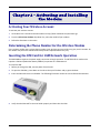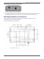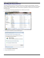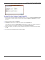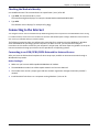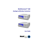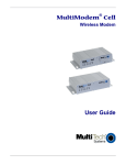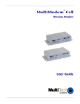
1
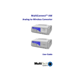
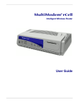
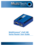
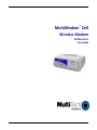
® MultiModem Cell Wireless Modem MTCBA‐H3‐U1 User Guide Copyright and Technical Support MultiModem® Cell User Guide Wireless Modem MTCBA‐H3‐U1 Part Number S000512C, Revision C Copyright This publication may not be reproduced, in whole or in part, without prior expressed written permission from Multi‐Tech Systems, Inc. All rights reserved. Copyright © 2013 by Multi‐Tech Systems, Inc. Multi‐Tech Systems, Inc. makes no representation or warranties with respect to the contents hereof and specifically disclaims any implied warranties of merchantability or fitness for any particular purpose. Furthermore, Multi‐Tech Systems, Inc. reserves the right to revise this publication and to make changes from time to time in the content hereof without obligation of Multi‐Tech Systems, Inc., to notify any person or organization of such revisions or changes. Check Multi‐ Tech’s website for current versions of our product documentation. Revision History Revision A B C Date 10/17/11 1/04/2013 1/31/2013 Description Initial release. Updated RoHS and other regulatory information. Removed EV1 model information. Trademarks and Logos The Multi‐Tech logo and MultiModem are registered trademarks of Multi‐Tech Systems, Inc. Windows is a registered trademark of Microsoft in the U.S. and other countries. Other trademarks and trade names mentioned in this publication belong to their respective owners. Contacting Multi‐Tech Support In order to better serve our customers, manage support requests and shorten resolution times, we have created the online web portal allowing you to submit questions regarding Multi‐Tech products directly to our technical support team. Get answers to your most complex questions, ranging from implementation, troubleshooting, product configuration, firmware upgrades and much more. To create an account and submit a Support Case on the Portal, visit https://support.multitech.com Online Web Portal https://support.multitech.com The Knowledge Base provides immediate answers to your questions and gives you access to support resolutions for all Multi‐Tech products. Visit our support area on the website for other support services. Knowledge Base and Support Services www.multitech.com/support.go World Headquarters Multi‐Tech Systems, Inc. 2205 Woodale Drive Mounds View, Minnesota 55112 Phone: 763‐785‐3500 or 800‐328‐9717 Fax: 763‐785‐9874 Technical Support Business Hours: M‐F, 9am to 5pm CST Country Europe, Middle East, Africa: U.S., Canada, all others: By Email [email protected] [email protected] Warranty To read the warranty statement for your product, visit: By Phone +(44) 118 959 7774 (800) 972‐2439 or (763) 717‐5863 http://www.multitech.com/warranty.go 2 Multi‐Tech Systems, Inc. MultiModem Cell User Guide Contents Contents Chapter 1 – Product Description and Specifications .......................................................................................... 5 Product Description .................................................................................................................................................. 5 Related Documentation ............................................................................................................................................ 5 MultiModem MTCBA‐H3‐U1 ......................................................................................................................................... 5 Safety ....................................................................................................................................................................... 5 General Safety ............................................................................................................................................................... 5 RF Interference Issues ................................................................................................................................................... 5 Vehicle Safety ................................................................................................................................................................ 6 Maintenance of the Wireless MultiModem .................................................................................................................. 6 Handling Precautions ..................................................................................................................................................... 6 Front Panel Overview ................................................................................................................................................ 6 LEDs ............................................................................................................................................................................... 7 Package Contents ...................................................................................................................................................... 7 Unbundled Package without Accessories ...................................................................................................................... 7 Bundled Package with Accessories ................................................................................................................................ 7 Specifications ............................................................................................................................................................ 8 Chapter 2 – Activating and Installing the Modem ........................................................................................... 10 Activating Your Wireless Account ............................................................................................................................ 10 Determining the Phone Number for the Wireless Modem ....................................................................................... 10 Inserting the SIM Card for GSM Network Operation ................................................................................................ 10 Connecting the Antenna and USB Cable .................................................................................................................. 11 Mounting the Modem on a Flat Surface .................................................................................................................. 11 Installing the Huawei Driver .................................................................................................................................... 12 Verifying That Your Modem is Properly Installed ........................................................................................................ 13 Chapter 3 – Using the Wireless Modem .......................................................................................................... 14 Using AT Commands to Verify Signal Strength and Roaming Status .......................................................................... 14 Verifying Signal Strength ............................................................................................................................................. 14 Checking Network Registration and Roaming Status .................................................................................................. 14 Checking the Modem’s Identity .................................................................................................................................. 15 Connecting to the Internet ...................................................................................................................................... 15 Connecting to an GSM/GPRS/HSPA Network for Internet Access .............................................................................. 15 Creating a Dial‐Up Connection in Windows Vista and XP ........................................................................................... 16 Creating a Dial‐Up Connection in Windows 7 ............................................................................................................. 17 Disconnecting .............................................................................................................................................................. 17 Using a Generic Dial‐Up Method to Connect .............................................................................................................. 18 Appendix A – Regulatory Compliance ............................................................................................................. 19 EMC, Safety, and R&TTE Directive Compliance ........................................................................................................ 19 International Modem Restrictions ........................................................................................................................... 19 FCC Part 15 Class B Statement ................................................................................................................................. 19 Industry Canada ...................................................................................................................................................... 20 Multi‐Tech Systems, Inc. MultiModem Cell User Guide 3 Contents Appendix B ‐ Cellular Information .................................................................................................................. 21 Antenna System for Cellular Devices ....................................................................................................................... 21 FCC Requirements for the Antenna ......................................................................................................................... 21 Antenna Specifications ............................................................................................................................................ 21 CDMA/EVDO Antenna Requirements/Specifications .................................................................................................. 21 GSM/HSPA/GPRS Antenna Requirements/Specifications ........................................................................................... 22 PTCRB Requirements for the Antenna ........................................................................................................................ 22 Antennas Available from Multi‐Tech Systems, Inc. ..................................................................................................... 22 Appendix C – Environmental Information ....................................................................................................... 23 Waste Electrical and Electronic Equipment Statement ............................................................................................. 23 WEEE Directive ............................................................................................................................................................ 23 Instructions for Disposal of WEEE by Users in the European Union ........................................................................... 23 REACH Statement ................................................................................................................................................... 24 Registration of Substances: ......................................................................................................................................... 24 Substances of Very High Concern (SVHC) .................................................................................................................... 24 Restriction of the Use of Hazardous Substances (RoHS) ........................................................................................... 24 4 Multi‐Tech Systems, Inc. MultiModem Cell User Guide Chapter 1 – Product Description and Specifications Product Description The Multi‐Tech MultiModem® Cell cellular modems are ready‐to‐deploy, standalone modems that provide wireless data communication and integrate seamlessly with virtually any application. The MultiModem Cell cellular modem is based on industry‐standard open interface and uses Multi‐Tech’s Universal Socket design. The Cell modem is designed with a quad‐band GSM/GPRS/HSPA network. The modems include a USB interface. If desired, you can mount the modem on a flat surface, such as a desktop or panel. Model MTCBA‐H3‐U1 Description The MTCBA‐H3‐U1 wireless modem offers fast cellular data speeds by using HSPA technology. The modem is equipped with quad‐band technology and can be used on all existing GSM networks, and most HSPA networks. Related Documentation MultiModem MTCBAH3U1 Use the HSPA‐H3 AT commands to configure the MTCBA‐H3‐U1 modem. These commands are documented in the HSPA‐H3 AT Commands Reference Guide part number S000505x. Safety General Safety The modem is designed for and intended to be used in fixed and mobile applications. “Fixed” means that the device is physically secured at one location and is not able to be easily moved to another location. “Mobile” means that the device is designed to be used in other than fixed locations. Caution: Maintain a separation distance of at least 20 cm (8 inches) between the transmitter’s antenna and the body of the user or nearby persons. The Modem is not designed for or intended to be used in portable applications within 20 cm (8 inches) of the body of the user. RF Interference Issues It is important to follow any special regulations regarding the use of radio equipment due in particular to the possibility of radio frequency, RF, interference. Please follow the safety advice given below carefully. ● Switch OFF your MultiModem when in an aircraft. The use of cellular telephones in an aircraft may endanger the operation of the aircraft, disrupt the cellular network and is illegal. Failure to observe this instruction may lead to suspension or denial of cellular telephone services to the offender, or legal action or both. Multi‐Tech Systems, Inc. MultiModem Cell User Guide 5 Chapter 1 – Product Description and Specifications ● Switch OFF your MultiModem when around gasoline or diesel‐fuel pumps and before filling your vehicle with fuel. ● Switch OFF your MultiModem in hospitals and any other place where medical equipment may be in use. ● Respect restrictions on the use of radio equipment in fuel depots, chemical plants or where blasting operations are in progress. ● There may be a hazard associated with the operation of your MultiModem close to inadequately protected personal medical devices such as hearing aids and pacemakers. Consult the manufacturers of the medical device to determine if it is adequately protected. ● Operation of your MultiModem close to other electronic equipment may also cause interference if the equipment is inadequately protected. Observe any warning signs and manufacturers’ recommendations. Vehicle Safety ● Do not use your MultiModem while driving. ● Respect national regulations on the use of cellular telephones in vehicles. Road safety always comes first. ● If incorrectly installed in a vehicle, the operation of MultiModem telephone could interfere with the correct functioning of vehicle electronics. To avoid such problems, be sure that qualified personnel have performed the installation. Verification of the protection of vehicle electronics should be part of the installation. ● The use of an alert device to operate a vehicle’s lights or horn on public roads is not permitted. Maintenance of the Wireless MultiModem Your wireless MultiModem is the product of advanced engineering, design, and craftsmanship. Treat it with care. The suggestions that follow help ensure you can enjoy this product for many years. ● Do not expose the MultiModem to any extreme environment where the temperature or humidity is high. ● Do not attempt to disassemble the MultiModem. There are no user serviceable parts inside. ● Do not expose the MultiModem to water, rain, or spilled beverages. It is not waterproof. ● Do not abuse your MultiModem by dropping, knocking, or shaking it. Rough handling can damage it. ● Do not place the MultiModem alongside computer discs, credit or travel cards, or other magnetic media. The information contained on discs or cards may be affected by the phone. ● The use of accessories not authorized by Multi‐Tech or not compliant with Multi‐Tech’s accessory specifications may invalidate the warranty of the MultiModem. ● In the unlikely event of a fault in the MultiModem, contact Multi‐Tech Technical Support. Handling Precautions All devices must be handled with certain precautions to avoid damage due to the accumulation of static charge. Although input protection circuitry has been incorporated into the devices to minimize the effect of this static build up, proper precautions should be taken to avoid exposure to electrostatic discharge during handling and mounting. Front Panel Overview The front panel includes an LED that indicates the status of the link. Another LED indicates whether the modem has power. The SIM door on the right side of the modem provides access to the SIM card holder if needed. 6 Multi‐Tech Systems, Inc. MultiModem Cell User Guide Chapter 1 – Product Description and Specifications LEDs LS When lit, indicates the radio module has power. PWR When lit, the unit is receiving power from the USB connection. Package Contents Note: For the MTCBA‐H3‐U1 modem, your wireless provider supplies the SIM card. Unbundled Package without Accessories 1 modem Note: You must supply mounting screws, USB cable, and an antenna. Bundled Package with Accessories 1 modem 1 antenna USB cable Note: You must supply mounting screws Multi‐Tech Systems, Inc. MultiModem Cell User Guide 7 Chapter 1 – Product Description and Specifications Specifications Feature Standard Band, Frequency Packet Data Circuit‐Switched Data Short Message Services (SMS) Antenna Connector SIM Connector USB Connector Voltage USB Power MTCBA‐H3‐U1 HSPA Quad‐band HSUPA/HSDPA/UMTS 850/900/1900/2100MHz Quad‐band GPRS/EDGE 850/900/1800/1900MHz HSDPA data service of up to 7.2 Mbps HSUPA data service of up to 5.76 Mbps UMTS up to 384 Kbps Up to 14.4K bps, non‐transparent Text and PDU, Point‐to‐Point (MO/MT), cell broadcast RF Antenna: 50 ohm SMA (female connector) Standard 1.8 and 3V SIM receptacle Type B 5.0V USB input voltage supplied by USB connector 500mA nominal current GSM850 Sleep 0.097A, 0.487W Typical 0.190A, .0946W Max .680A, 3.24W Peak 1.400A HSDPA Physical Description Operating Temperature Storage Temperature Humidity 8 Sleep 0.097A, 0.487W Typical 0.428A, 2.08W Max .700, 3.33W Peak .930A Inrush current: 1.08A 4.75” W x 1.58”H x 2.89”D 5.2oz 12.06cmW x 4.01cmH x 7.34cmD 0.147Kg ‐10° to 55° C ‐40° to 85° C Relative humidity 20% to 90% noncondensing Multi‐Tech Systems, Inc. MultiModem Cell User Guide Certifications Chapter 1 – Product Description and Specifications EMC Compliance FCC Part 15 Class B EN55022 Class B EN55024 Radio Compliance FCC Part 22, 24 RSS 132, 133 EN301 489‐1 EN301 489‐7 EN301 489‐24 Safety UL60950‐1 2nd Ed. IEC60950‐1: 2005 (Second edition with EN 60950‐1:2006+A11:2009) Network Compliance PTCRB AT&T Multi‐Tech Systems, Inc. MultiModem Cell User Guide 9 Chapter 2 – Activating and Installing the Modem Activating Your Wireless Account To activate your wireless account: 1. Go to Multi‐Tech’s Cellular Activation website at http://www.multitech.com/activation.go. 2. From the Select Your Product drop‐down list, select the model of your modem. 3. Follow the directions on the notice. Determining the Phone Number for the Wireless Modem Every wireless modem has a unique phone number. Your wireless service provider may give you this number. Or the number may be on the SIM card. Wireless provider implementations may vary. Inserting the SIM Card for GSM Network Operation The MultiModem requires the power supply connection to begin operation. The MTCBA‐H3‐U1 modem also requires a SIM card (Subscriber Identity Module) to operate on a GSM network. To install the SIM: 1. Before you change the SIM, remove power from the unit. 2. To open the SIM door, press down on the tab on the top of the door and pry open the door. 3. Insert the SIM card into the card holder. The following illustration shows the correct SIM card orientation. 4. Verify that the SIM card fits into the holder properly and then close the door. 10 Multi‐Tech Systems, Inc. MultiModem Cell User Guide Chapter 2 – Activating and Installing the Modem Connecting the Antenna and USB Cable 1. Connect a suitable antenna to the ANT connector. 2. The USB cable uses 500mA from the USB power line. Connect one end of the USB cable to your computer or other USB high power device, such as a hub. Connect the other end to the modem USB connector. Mounting the Modem on a Flat Surface You can mount the modem on a flat surface, if desired. To properly place mounting screws, use the measurements shown in the illustration that follows. Use #6 pan head screws for all mount locations. Multi‐Tech Systems, Inc. MultiModem Cell User Guide 11 Chapter 2 – Activating and Installing the Modem Installing the Huawei Driver The following instructions help you install the Huawei driver for a computer using the Windows 7 operating system. Computer operating systems can differ. As such, you may need to modify the instructions in this section to allow for your computer’s unique setup. Use these steps as a guideline to install the driver for all Windows operating systems. 1. From the Multi‐Tech website, download drivers to a folder on your local PC. 2. From this folder, select DriverSetup.exe file. 3. The Program Compatibility Assistant window appears. 4. Select This program installed correctly. 5. Plug the USB cable into the PC. 12 Multi‐Tech Systems, Inc. MultiModem Cell User Guide 6. Chapter 2 – Activating and Installing the Modem When the Driver Software Installation window states “Your device is ready to use”, your modem is installed. Verifying That Your Modem is Properly Installed 1. After you have successfully installed the MultiModem driver, you return to the Phone and Modems Options window. Make sure that the modem is now listed under the column Modem and Attached To (the correct com port). 2. Select the modem and then click Properties. 3. A Properties window opens for the Multi‐Tech modem. Click the Diagnostics tab. In the middle of the window, click Query Modem. Windows queries the Multi‐Tech modem. If the query is successful a group on the tab appears, showing the columns Command and Response. 4. If this process passes, your modem is properly installed and ready for use. To close the Properties window, click OK. 5. To close the Phone and Modems Options window, click OK. Multi‐Tech Systems, Inc. MultiModem Cell User Guide 13 Chapter 3 – Using the Wireless Modem Using AT Commands to Verify Signal Strength and Roaming Status You can use AT commands to operate, configure, and query your modem. Reference guides document the AT commands. You can download these guides from the Multi‐Tech website. To verify signal strength and roaming status, you must use a terminal application such as HyperTerminal. To open this program in Windows XP, go to Start > All Programs > Accessories > Communications > HyperTerminal. Other Windows operating systems have similar paths to HyperTerminal. See your system’s online Help if you cannot find HyperTerminal. Verifying Signal Strength To verify signal strength: 1. Open a terminal program of your choosing. 2. Type AT+CSQ The modem responds with the received signal strength (rssi) and the channel bit error rate (ber). RSSI ranges from 0 to 31. Signal Strength Verification – RSSI AT+CSQ xx Values Signal Strength 0 ‐ 10 Weak or Insufficient 11 ‐ 20 Average 21 – 31 Exceptional 99 No signal BER ranges from 0 to 7 (Seven is the highest error rate). Checking Network Registration and Roaming Status To verify that the MultiModem is registered on the wireless network: 1. Open HyperTerminal. 2. Type AT+CREG? The modem responds in one of the following ways: Value 0,0 0,1 0,5 Network Registration Verification Network Registration Status The modem is not registered on any network If not registered, verify the signal strength. The received signal might not be strong enough for the modem to register. The modem is registered on the home network. The modem is registered on a network and it is roaming. 14 Multi‐Tech Systems, Inc. MultiModem Cell User Guide Chapter 3 – Using the Wireless Modem Checking the Modem’s Identity Use the ATI command. This command uses the capital letter I (not L) after AT. ● Type ATI0. The command ends in a zero. The manufacturing data displays, for example: Huawei Modem Multiband G850 1900 ● Type ATI3 The software version displays, for example: 651_09gg... Connecting to the Internet You configure Internet access in Windows Dial‐Up Networking (DUN) of the computer that the MultiModem Cell is serving. For a GPRS network, create an Access Point Name in the Phone and Modem Options dialog in Windows Control Panel and then create your Windows Dial‐Up Connection (DUN). The following instructions help you configure the connection for a computer using the Windows 7, Windows Vista and Windows XP operating systems. Computers can differ. As such, you may need to modify the instructions in this section to allow for your computer’s unique setup. Use these steps as a guideline to set up an Internet connection through your wireless service provider for all operating systems. Connecting to an GSM/GPRS/HSPA Network for Internet Access After you insert the SIM card and complete all other setup steps, establish an Internet connection through a Windows dial‐up session. Before You Begin ● Make sure you have one HSPA capable MultiModem cell modem. ● The MultiModem modem has a HSPA capable network and an active SIM card. ● The modem must receive a proper signal and have network registration through the wireless provider’s network. ● Install the Multi‐Tech drivers on a computer running Windows 7, Vista or XP. Multi‐Tech Systems, Inc. MultiModem Cell User Guide 15 Chapter 3 – Using the Wireless Modem Setting the Access Point Name (APN) for MTCBA‐H3‐U1 So your MTCBA‐H3‐U1 modem can connect to your provider’s network, set the modem’s APN. The APN is a server name that your account is setup on with your provider. You provider gives you the APN. Some APNs include: ● AT&T; PROXY, or INTERNET, or PUBLIC ● T‐Mobile: INTERNET2. VOICESTREAM.COM, INTERNET3.VOICESTREAM.COM, EPC.Tmobile.com or WAP.VOICESTREAM.COM To set the APN: 1. From the Start button, select Control Panel. 2. In Control Panel, double‐click Phone and Modem Options. 3. In the Phone and Modem Options window, click the Modems tab. Highlight your Cell modem listed in the table and then click Properties. 4. A Properties window for your modem opens. For Windows Vista and later operating systems, click Change Settings. 5. Click the Advanced tab. 6. From the Extra Settings group, in the Extra initialization commands text box, enter: a. AT+CGDCONT=1,”IP”,”<APN>” b. For <APN>, enter in the correct APN for your account. For example: AT+CGDCONT=1”IP”,”ISP.AT&T” 7. To close the Properties window, click OK. 8. To close the Phone and Modems Options window click OK. Creating a DialUp Connection in Windows Vista and XP 1. From the Start button, select Control Panel. 2. In the Control Panel, double click Network Connections. 3. From the Network Connections window, in the Network Tasks group, click Create a new connection. 4. The New Connection Wizard opens, and steps you through the setup of an Internet connection. To begin, click Next. 5. On the Network Connection Type pane, select Connect to the Internet. Click Next. 6. On the Getting Ready pane, select Set up my connection manually. Click Next. 7. On the Internet Connection pane, select Connect using a dial‐up modem. Click Next. After clicking Next, you may be asked to select which modem to use. If you have more than one modem installed in your computer, select the proper Multi‐Tech wireless modem. 8. On the Connection Name pane, in the ISP Name box, type in a name for your new connection. Use any name you desire, then click Next. 9. On the Phone Number to Dial pane, type the number that the modem can use to connect to your provider’s Internet service. 16 ● For HSPA modems, type in the number *99***1#. Then click Next. ● For EV‐DO modems, type in the number #777. Then click Next. Multi‐Tech Systems, Inc. MultiModem Cell User Guide Chapter 3 – Using the Wireless Modem 10. On the Connection Availability pane, specify if this connection is for anyone’s use or for your use only. Click Next. 11. On the Internet Account Information pane, type the user name and the password for your account. In many cases, a user name and a password are not required. However, some wireless providers require this information. Check with your provider to determine if the user name and password are required. 12. Check the following options if you want to active them: ● Check the box if you want this account name and password to be used by everyone. ● Check the box if you want this as your default Internet connection. ● Click Next. 13. On the Completing the New Connection Wizard pane, indicate if you want to add a shortcut to your desktop. Click Finish. 14. A Connection window appears on your desktop. Click Properties. 15. The Properties window opens, where you can make your connection. Note: Make sure that Use dialing rules is not selected. Click OK. 16. Once back at the Connection window, to connect, click Dial. 17. The modem connects to your provider’s Internet service. Once connected, the connection status icon appears in your system tray. You can open an Internet browser to access the Internet. Creating a DialUp Connection in Windows 7 1. From the Start button, select Control Panel. 2. From the Adjust your computer’s settings window, select Network and Internet. 3. From the Network and Internet window, select Network and Sharing Center. 4. In the window that appears, in the Change your networking settings group, select Set up a new connection or network. 5. In the Choose a connection option window, select Set up a dial up connection. Click Next. 6. In the window that appears, type the information about the connection that you received from your Internet service provider, including: Service provider Dial‐up phone number User name Password Connection name 7. Click Connect. Disconnecting 1. To disconnect, click on the connection icon in your system tray. 2. Right click on your current connection. 3. Select Disconnect. The modem disconnects from the Internet. Multi‐Tech Systems, Inc. MultiModem Cell User Guide 17 Chapter 3 – Using the Wireless Modem Using a Generic DialUp Method to Connect Users of computers that are not running a Windows operating system can use a generic dial‐up method to connect to the Internet. 1. To set up an Access Point Name (APN) enter: AT+CGDCONT=1,“IP”,”<APNSERVER>” where <APNSERVER> is the APN server supplied by your carrier. 2. Use ATD*99***1# to dial into the network. 18 Multi‐Tech Systems, Inc. MultiModem Cell User Guide Appendix A – Regulatory Compliance EMC, Safety, and R&TTE Directive Compliance The CE mark is affixed to this product to confirm compliance with the following European Community Directives: Council Directive 2004/108/EC of 31 December 2004 on the approximation of the laws of Member States relating to electromagnetic compatibility; and Council Directive 2006/95/EC of 12 December 2006 on the harmonization of the laws of Member States relating to electrical equipment designed for use within certain voltage limits; and Council Directive 1999/5/EC of 9 March 1999 on radio equipment and telecommunications terminal equipment and the mutual recognition of their conformity. International Modem Restrictions Some dialing and answering defaults and restrictions may vary for international modems. Changing settings may cause a modem to become non‐compliant with national telecom requirements in specific countries. Also note that some software packages may have features or lack restrictions that may cause the modem to become non‐ compliant. FCC Part 15 Class B Statement This equipment has been tested and found to comply with the limits for a Class B digital device, pursuant to part 15 of the FCC Rules. These limits are designed to provide reasonable protection against harmful interference in a residential installation. This equipment generates, uses, and can radiate radio frequency energy and, if not installed and used in accordance with the instructions, may cause harmful interference to radio communications. However, there is no guarantee that interference will not occur in a particular installation. If this equipment does cause harmful interference to radio or television reception, which can be determined by turning the equipment off and on, the user is encouraged to try to correct the interference by one or more of the following measures: ● Reorient or relocate the receiving antenna. ● Increase the separation between the equipment and receiver. ● Connect the equipment into an outlet on a circuit different from that to which the receiver is connected. ● Consult the dealer or an experienced radio/TV technician for help. Warning: Changes or modifications to this unit not expressly approved by the party responsible for compliance could void the user’s authority to operate the equipment. Multi‐Tech Systems, Inc. MultiModem Cell User Guide 19 Appendix A – Regulatory Compliance Industry Canada This Class B digital apparatus meets all requirements of the Canadian Interference‐Causing Equipment Regulations. Cet appareil numérique de la classe B respecte toutes les exigences du Reglement Canadien sur le matériel brouilleur. This device complies with Industry Canada RSS Appliance radio exempt from licensing. The operation is permitted for the following two conditions: 1. the device may not cause harmful interference, and 2. the user of the device must accept any interference suffered, even if the interference is likely to jeopardize the operation. Le présent appareil est conforme aux CNR d'Industrie Canada applicables aux appareils radio exempts de licence. L'exploitation est autorisée aux deux conditions suivantes: 1. l'appareil ne doit pas produire de brouillage, et 2. l'utilisateur de l'appareil doit accepter tout brouillage radioélectrique subi, même si le brouillage est susceptible d'en compromettre le fonctionnement. 20 Multi‐Tech Systems, Inc. MultiModem Cell User Guide Appendix B - Cellular Information Antenna System for Cellular Devices Wireless performance depends on implementation and antenna design. The integration of the antenna system into the product is a critical part of the design process; therefore, it is essential to consider it early so performance is not compromised. If you make changes to the certified antenna system of the MultiModem, then recertification is required by specific network carriers such as Sprint. The antenna system is defined as the UFL connection point from the MultiModem to the specified cable specifications and specified antenna specifications. FCC Requirements for the Antenna The antenna gain, including cable loss, for the radio you are incorporating into your product design must not exceed the requirements at 850 MHz and 1900 MHz as specified by the FCC grant for mobile operations and fixed mounted operations as defined in 2.1091 and 1.1307 of the FCC rules for satisfying RF exposure compliance. The antenna used for transmitting must be installed to provide a separation distance of at least 20cm from all persons and must not transmit simultaneously with any other antenna transmitters. User and installers must be provided with antenna installation instructions and transmitter operating conditions to satisfying RF exposure compliance. Antenna Specifications CDMA/EVDO Antenna Requirements/Specifications Frequency Range Impedance VSWR Typical Radiated Gain Radiation Polarization TRP/TIS 824 – 894 MHz / 1850 – 1990 MHz 50 Ohms VSWR shall not exceed 2.0:1 at any point across the bands of operation 3 dBi on azimuth plane Omni‐directional Vertical The total radiated power (TRP) at the antenna shall be no less than +21/20 dBm for PCS/Cell channels respectively, and the total isotropic sensitivity (TIS) at the antenna shall be no less than ‐104/104 dBm for PCS/Cell channels respectively. Multi‐Tech Systems, Inc. MultiModem Cell User Guide 21 Appendix B ‐ Cellular Information GSM/HSPA/GPRS Antenna Requirements/Specifications Frequency Range Impedance VSWR Typical Radiated Gain Radiation Polarization TRP/TIS 824 – 960 MHz / 1710 – 1990 MHz 50 Ohms VSWR shall not exceed 2.0:1 at any point across the bands of operation 3 dBi on azimuth plane Omni‐directional Vertical Including cable loss the total radiate power (TRP) at the antenna shall be no less than +22/24.5 dBm for 850/1900 MHz respectively, and the total isotropic sensitivity (TIS) at the antenna shall be no less than ‐99/101.5 dBm for 850/1900 MHz respectively. PTCRB Requirements for the Antenna Do not alter the authorized antenna system. The antenna system must maintain the same specifications. The antenna must be the same type, with similar in‐band and out‐of‐band radiation patterns. Antennas Available from MultiTech Systems, Inc. 22 Quad Band Description Qty Part Number Hinged Right Angle 800/900/1800/1900 MHz Cellular Modem Antenna Hinged Right Angle 800/900/1800/1900 MHz Cellular Modem Antenna Hinged Right Angle 800/900/1800/1900 MHz Cellular Modem Antenna 1 10 50 ANQB‐1HRA ANQB‐10HRA ANQB‐50HRA Dual Band Description Qty Part Number Hinged Right Angle 900/1800 MHz Cellular Modem Antenna Hinged Right Angle 900/1800 MHz Cellular Modem Antenna Hinged Right Angle 900/1800 MHz Cellular Modem Antenna Hinged Right Angle 800/1900 MHz Cellular Modem Antenna Hinged Right Angle 800/1900 MHz Cellular Modem Antenna Hinged Right Angle 800/1900 MHz Cellular Modem Antenna 1 10 50 1 10 50 ANF1‐1HRA ANF1‐10HRA ANF1‐50HRA ANCF2‐1HRA ANCF2‐10HRA ANCF2‐501HRA Mag Mount Dual Band Description Qty Part Number Mag Mount 900/1800 MHz 1/2 Wave Cellular Antenna, 12.5" Mag Mount 900/1800 MHz 1/2 Wave Cellular Antenna, 12.5" Mag Mount 900/1800 MHz 1/2 Wave Cellular Antenna, 12.5" Mag Mount 900/1800 MHz 1/4 Wave Cellular Antenna, 4" Mag Mount 900/1800 MHz 1/4 Wave Cellular Antenna, 4" Mag Mount 900/1800 MHz 1/4 Wave Cellular Antenna, 4" Mag Mount 850/1900 MHz 1/2 Wave Cellular Antenna, 12.5" Mag Mount 850/1900 MHz 1/2 Wave Cellular Antenna, 12.5" Mag Mount 850/1900 MHz 1/2 Wave Cellular Antenna, 12.5" Mag Mount 850/1900 MHz 1/4 Wave Cellular Antenna, 4" Mag Mount 850/1900 MHz 1/4 Wave Cellular Antenna, 4" Mag Mount 850/1900 MHz 1/4 Wave Cellular Antenna, 4" 1 10 50 1 10 50 1 10 50 1 10 50 ANF1‐1MMHW ANF1‐10MMHW ANF1‐50MMHW ANF1‐1MMQW ANF1‐10MMQW ANF1‐50MMQW ANCF2‐1MMHW ANCF2‐10MMHW ANCF2‐50MMHW ANCF2‐1MMQW ANCF2‐10MMQW ANCF2‐50MMQW Multi‐Tech Systems, Inc. MultiModem Cell User Guide Appendix C – Environmental Information Waste Electrical and Electronic Equipment Statement WEEE Directive The WEEE Directive places an obligation on EU‐based manufacturers, distributors, retailers, and importers to take‐back electronics products at the end of their useful life. A sister directive, ROHS (Restriction of Hazardous Substances) complements the WEEE Directive by banning the presence of specific hazardous substances in the products at the design phase. The WEEE Directive covers all Multi‐Tech products imported into the EU as of August 13, 2005. EU‐based manufacturers, distributors, retailers and importers are obliged to finance the costs of recovery from municipal collection points, reuse, and recycling of specified percentages per the WEEE requirements. Instructions for Disposal of WEEE by Users in the European Union The symbol shown below is on the product or on its packaging, which indicates that this product must not be disposed of with other waste. Instead, it is the user’s responsibility to dispose of their waste equipment by handing it over to a designated collection point for the recycling of waste electrical and electronic equipment. The separate collection and recycling of your waste equipment at the time of disposal will help to conserve natural resources and ensure that it is recycled in a manner that protects human health and the environment. For more information about where you can drop off your waste equipment for recycling, please contact your local city office, your household waste disposal service or where you purchased the product. July, 2005 Multi‐Tech Systems, Inc. MultiModem Cell User Guide 23 Appendix C – Environmental Information REACH Statement Registration of Substances: After careful review of the legislation and specifically the definition of an “article” as defined in EC Regulation 1907/2006, Title II, Chapter 1, Article 7.1(a)(b), it is our current view Multi‐Tech Systems, Inc. products would be considered as “articles”. In light of the definition in § 7.1(b) which requires registration of an article only if it contains a regulated substance that “is intended to be released under normal or reasonable foreseeable conditions of use,” our analysis is that Multi‐Tech Systems, Inc. products constitute nonregisterable articles for their intended and anticipated use. Substances of Very High Concern (SVHC) Per the candidate list of Substances of Very high Concern (SVHC) published October 28, 2008 we have reviewed these substances and certify the Multi‐Tech Systems, Inc. products are compliant per the EU “REACH” requirements of less than 0.1% (w/w) for each substance. If new SVHC candidates are published by the European Chemicals Agency, and relevant substances have been confirmed, that exceeds greater than 0.1% (w/w), Multi‐Tech Systems, Inc. will provide updated compliance status. Multi‐Tech Systems, Inc. also declares it has been duly diligent in ensuring that the products supplied are compliant through a formalized process which includes collection and validation of materials declarations and selective materials analysis where appropriate. This data is controlled as a part of a formal quality system and will be made available upon request. Restriction of the Use of Hazardous Substances (RoHS) Multi‐Tech Systems, Inc. Certificate of Compliance 2011/65/EU Multi‐Tech Systems confirms that its embedded products comply with the chemical concentration limitations set forth in the directive 2011/65/EU of the European Parliament (Restriction of the use of certain Hazardous Substances in electrical and electronic equipment ‐ RoHS) These Multi‐Tech products do not contain the following banned chemicals1: ● Lead, [Pb] < 1000 PPM ● Mercury, [Hg] < 1000 PPM ● Hexavalent Chromium, [Cr+6] < 1000 PPM ● Cadmium, [Cd] < 100 PPM ● Polybrominated Biphenyl, [PBB] < 1000 PPM ● Polybrominated Diphenyl Ether, [PBDE] < 1000 PPM Environmental considerations: ● Moisture Sensitivity Level (MSL) =1 Maximum Soldering temperature = 260C (in SMT reflow oven) 1Lead usage in some components is exempted by the following RoHS annex, therefore higher lead concentration would be found in some modules (>1000 PPM); –Resistors containing lead in a glass or ceramic matrix compound. 24 Multi‐Tech Systems, Inc. MultiModem Cell User Guide