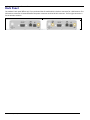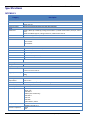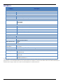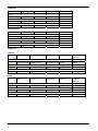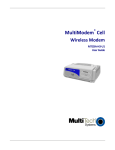
1
MultiModem® iCell Intelligent Wireless Modem User Guide MultiModem® iCell User Guide Intelligent Wireless Modem MTCMR‐E1, ‐C1, ‐G2, ‐H5, ‐EV2, optional ‐GP builds S000484H, Revision H Copyright This publication may not be reproduced, in whole or in part, without prior expressed written permission from Multi‐Tech Systems, Inc. All rights reserved. Copyright © 2013 by Multi‐Tech Systems, Inc. Multi‐Tech Systems, Inc. makes no representation or warranties with respect to the contents hereof and specifically disclaims any implied warranties of merchantability or fitness for any particular purpose. Furthermore, Multi‐Tech Systems, Inc. reserves the right to revise this publication and to make changes from time to time in the content hereof without obligation of Multi‐Tech Systems, Inc., to notify any person or organization of such revisions or changes. Check Multi‐Tech’s Web site for current versions of our product documentation. Revision History Revision Date A B C D E F 05/17/10 06/07/10 07/06/10 10/21/10 07/29/11 12/11/12 G H 02/04/13 05/08/13 Description Initial release of E1 build. Release to add C1 build. Release to add G2 build and –GP build options. Release to add H4, EV2 builds and –GP build options. Removed references to CD. Release to add H5. Added pacemaker statement. Updated RoHS and other regulatory information. HSPA to HSPA+ Updated specifications Trademarks and Logos The Multi‐Tech logo and MultiModem are registered trademarks of Multi‐Tech Systems, Inc. Windows is a registered trademark of Microsoft in the U.S. and other countries. Other trademarks and trade names mentioned in this publication belong to their respective owners. Contacting Multi‐Tech Support In order to better serve our customers, manage support requests and shorten resolution times, we have created the online web portal allowing you to submit questions regarding Multi‐Tech products directly to our technical support team. Get answers to your most complex questions, ranging from implementation, troubleshooting, product configuration, firmware upgrades and much more. To create an account and submit a Support Case on the Portal, visit: https://support.multitech.com https://support.multitech.com The Knowledge Base provides immediate answers to your questions and gives you access to support resolutions for all Multi‐Tech products. Visit our support area on the website for other support services. Knowledge Base and Support Services www.multitech.com/support.go Online Web Portal World Headquarters Multi‐Tech Systems, Inc. 2205 Woodale Drive Mounds View, Minnesota 55112 Phone: 763‐785‐3500 or 800‐328‐9717 Fax: 763‐785‐9874 Technical Support Business Hours: M‐F, 9am to 5pm CST Country By Email By Phone Europe, Middle East, Africa: U.S., Canada, all others: [email protected] [email protected] +(44) 118 959 7774 (800) 972‐2439 or (763) 717‐5863 Warranty To read the warranty statement for your product, please visit: http://www.multitech.com/warranty.go 2 Multi‐Tech Systems, Inc. MultiModem iCell User Guide Contents Chapter 1 – Product Description and Specifications ............................................................................... 5 Related Documentation .......................................................................................................................................... 6 Universal IP .................................................................................................................................................................... 6 MultiModem MTCMR-E1 (EDGE) ............................................................................................................................... 6 MultiModem MTCMR-C1 (CDMA) .............................................................................................................................. 6 MultiModem MTCMR-G2 (GPRS) .............................................................................................................................. 6 MultiModem MTCMR-H5 (HSPA) ............................................................................................................................... 6 MultiModem MTCMR-EV2 (EV-DO) ........................................................................................................................... 6 Package Contents ................................................................................................................................................... 7 Safety ........................................................................................................................................................................ 7 General Safety ............................................................................................................................................................... 7 RF Interference Issues ................................................................................................................................................. 7 Interference with Pacemakers and Other Medical Devices .................................................................................... 7 Vehicle Safety ................................................................................................................................................................ 8 Maintenance of the Wireless MultiModem ................................................................................................................ 8 Handling Precautions ................................................................................................................................................... 8 Front Panel ............................................................................................................................................................... 9 LEDs................................................................................................................................................................................ 9 Back Panel .............................................................................................................................................................. 10 Specifications ......................................................................................................................................................... 11 MTCMR-E1 .................................................................................................................................................................. 11 MTCMR-C1 .................................................................................................................................................................. 13 MTCMR-G2 .................................................................................................................................................................. 14 MTCMR-H5 .................................................................................................................................................................. 15 MTCMR-EV2 ................................................................................................................................................................ 16 GPS Specifications ..................................................................................................................................................... 17 Power Specifications .................................................................................................................................................. 18 RF Specifications ................................................................................................................................................... 21 Antenna Specifications ......................................................................................................................................... 22 GSM/EGSM Antenna Requirements/Specifications .............................................................................................. 22 Antennas Available from Multi-Tech Systems, Inc. ................................................................................................ 22 PTCRB Requirements Note ...................................................................................................................................... 22 FCC Requirements Note ............................................................................................................................................ 22 Global Positioning System (GPS) ............................................................................................................................. 23 GPIO (General Purpose Input/Output) Connector ............................................................................................. 23 GPIO DC Characteristics ........................................................................................................................................... 24 RS232 9-Pin Functions of the Female End Connector ...................................................................................... 24 3 Multi‐Tech Systems, Inc. MultiModem iCell User Guide Chapter 2 – Activation and Installation ..................................................................................................... 25 Activating Your Wireless Account ....................................................................................................................... 25 Phone Numbers for the Wireless Modem ................................................................................................................ 25 Installing the SIM Card (if required) ..................................................................................................................... 25 Connecting the Antenna, Serial Cable, GPIO Cable, and Power ..................................................................... 26 Connecting Direct DC Power (Optional) .................................................................................................................. 27 Attaching the Modem to a Flat Surface ............................................................................................................... 27 Installing the USB Virtual COM Port .................................................................................................................... 28 Before You Begin ........................................................................................................................................................ 28 Installing the Modem Driver .................................................................................................................................. 29 Verifying that the Modem is Successfully Installed .......................................................................................... 33 Chapter 3 – Using Your Wireless Modem ................................................................................................. 34 Phone Numbers for the Wireless Modem ........................................................................................................... 34 Examples of Useful AT Commands ..................................................................................................................... 34 HyperTerminal ............................................................................................................................................................. 34 AT Commands ............................................................................................................................................................. 34 Checking the Modem’s Identity ................................................................................................................................. 35 Connecting to the Internet .................................................................................................................................... 35 Connecting to a CDMA Network for Internet Access ............................................................................................. 35 Connecting to an EDGE/GPRS Network for Internet Access ............................................................................... 35 Creating Dial-Up Connection in Windows Vista and XP ....................................................................................... 36 Generic Dial-Up Method - Non-Windows ................................................................................................................ 37 Appendix A – Regulatory Compliance ....................................................................................................... 39 EMC, Safety, and R&TTE Directive Compliance ................................................................................................ 39 International Modem Restrictions ........................................................................................................................ 39 FCC Part 15 Class B Statement ............................................................................................................................ 39 EMC Requirements for Industry Canada ............................................................................................................ 40 Waste Electrical and Electronic Equipment (WEEE) Statement ...................................................................... 40 WEEE Directive ........................................................................................................................................................... 40 Instructions for Disposal of WEEE by Users in the European Union .................................................................. 40 REACH Statement .................................................................................................................................................. 41 Restriction of the Use of Hazardous Substances (RoHS) ................................................................................ 41 Information on HS/TS Substances According to Chinese Standards ............................................................ 42 Information on HS/TS Substances According to Chinese Standards (in Chinese) ...................................... 43 Appendix B – DC Power Cable .................................................................................................................... 44 Index ................................................................................................................................................................ 45 Multi‐Tech Systems, Inc. MultiModem iCell User Guide 4 Chapter 1—Product Description and Specifications Chapter 1 – Product Description and Specifications The Multi‐Tech MultiModem® iCell is a mid‐range wireless modem containing an embedded TCP/IP protocol stack for Internet connectivity, serial and USB connectors for modem configuration, and a General Purpose Input/Output (GPIO) connector for customer interface connection. You can mount MultiModem iCells on a desktop or panel. Model MTCMR‐E1 MTCMR‐E1‐GP MTCMR‐C1 MTCMR‐C1‐GP MTCMR‐G2 MTCMR‐G2‐GP MTCMR‐H5 MTCMR‐H5‐GP MTCMR‐EV2 MTCMR‐EV2‐GP Description Quad‐band E‐GPRS Class 12 performance Quad‐band E‐GPRS Class 12 performance; GPS function Multi‐band CDMA2000 1xRTT performance Multi‐band CDMA2000 1xRTT performance; GPS function Quad‐band GSM/GPRS Class 10 performance Quad‐band GSM/GPRS Class 10 performance; GPS function Standards based tri‐band UMTS/HSPA performance Standards based tri‐band UMTS/HSPA performance; GPS function Dual‐band 800/1900 MHz with receive diversity support on EVDO bands Dual‐band 800/1900 MHz with receive diversity support on EVDO bands; GPS function The MTCMR contains an embedded TCP/IP protocol stack to bring Internet connectivity to any device without making changes to its hardware design. Using the Internet protocols and the wireless connection to an IP network, the modem sends and receives data over the Internet. The modem offers short message service (SMS) features such as text and PDU, Point‐to‐point (MT/MO) and cell broadcast. Cell broadcast is not available on EV2 models. The MultiModem iCell modem delivers some of the fastest cellular wireless data speeds using the various Internet protocols. This is ideal for highly data‐intensive applications such as remote video surveillance and other multimedia applications where you are sending digital images, web pages and photographs. The MultiModem iCell modem is designed around a wide variety of interface options including serial RS‐232, USB, and General Purpose Input/Output (GPIO). The serial RS‐232 and USB connections provide seamless connectivity for configuration of your application. The GPIO interface provides five user‐configurable GPIO’s as CMOS input or output ports to be connected to a customer’s peripheral device. A customer application in which the GPIO interface could be used is one with a monitoring device connected to the GPIO interface in which the monitoring device triggers an event in the IP stack to establish a TCP or UDP socket connection or send an email stating that the monitoring device was triggered by high water. 5 Multi‐Tech Systems, Inc. MultiModem iCell User Guide Chapter 1—Product Description and Specifications Related Documentation Universal IP All MultiModem iCell modems are equipped with an embedded TCP/IP protocol stack to automate the connection process and open a socket for bidirectional data transmission. Multi‐Tech’s Universal IP supports Telnet, SMTP/POP, FTP, TCP, UDP, PPP as well as other automatic call management options. AT Commands: The embedded TCP/IP stack on the MultiModem iCell modems is configured using the Universal IP (UIP) AT Commands. These commands are documented in the Reference Guide document number S000457x. MultiModem MTCMRE1 (EDGE) The MultiModem iCell MTCMR‐E1 wireless modem delivers some of the fastest cellular wireless data speeds using EDGE technology. It allows users to connect to the Internet, send and receive data up to three times faster than possible with an ordinary GSM/GPRS network making it ideal for highly data‐intensive multimedia applications. AT Commands: The MultiModem MTCMR‐E1 wireless modem is configured using the EDGE AT Commands. These commands are documented in the Reference Guide for the MultiModem Wireless EDGE Modems, document number S000474x. MultiModem MTCMRC1 (CDMA) The MultiModem iCell MTCMR‐C1 wireless modem offers standards‐based multi‐band CDMA2000 1xRTT performance. The ready‐to‐deploy, standalone modem allows developers to add wireless communication to products with a minimum of development time and expense. AT Commands: The MultiModem MTCMR‐C1 wireless modem is configured using the CDMA AT Commands. These commands are documented in the Reference Guide for the MultiModem Wireless CDMA Modems, document number S000478x. MultiModem MTCMRG2 (GPRS) The MultiModem iCell MTCMR‐G2 wireless modem offers standards‐based quad‐band GSM/GPRS Class 10 performance. Ready to deploy, standalone data modem allows developers to add wireless communication to products with a minimum of deployment time and expense. AT Commands: The MultiModem MTCMR‐G2 wireless modem is configured using the GPRS AT Commands. These commands are documented in the Reference Guide for the MultiModem Wireless GPRS Modems, document number S000463. MultiModem MTCMRH5 (HSPA) The MultiModem iCell MTCMR‐H5 delivers some of the fastest cellular data speeds by using HSPA technology. Based on industry‐standard open interfaces, the SocketModem cellular modem is equipped with quad‐band, high‐speed RS232 technology, which means it can be used worldwide on all existing GSM networks. AT Commands: The MultiModem MTCMR‐H5 wireless modem is configured using the HSPA AT Commands. These commands are documented in the Reference Guide number S000528x. MultiModem MTCMREV2 (EVDO) The MultiModem iCell MTCMR‐EV2 wireless modems are 3G units supporting CDMA EV‐DO Rev A and below. Based on industry‐standard open interfaces, the MultiModem iCell is equipped with dual‐band 800/1900 MHz bands with receive diversity support on both bands. AT Commands: The MultiModem MTCMR‐EV2 wireless modem is configured using the EV‐DO AT Commands. These commands are documented in the Reference Guide number S000482x. Multi‐Tech Systems, Inc. MultiModem iCell User Guide 6 Chapter 1—Product Description and Specifications Package Contents Note: Your wireless provider supplies the SIM card (not needed for ‐C1/ ‐EV2 versions). Unbundled Package with No Accessories 1 modem Note: You must supply mounting screws, AC or DC power supply, and antenna(s). Bundled Package with Accessories 1 modem 1 antenna (‐GP builds have an additional GPS antenna) 1 RS232 cable 1 USB cable 1 GPIO cable 1 power supply (‐GP builds do not include power supply) Note: You must supply mounting screws. Safety General Safety The modem is designed for and intended to be used in fixed and mobile applications. “Fixed” means that the device is physically secured at one location and is not able to be easily moved to another location. “Mobile” means that the device is designed to be used in other than fixed locations. Caution: Maintain a separation distance of at least 20 cm (8 inches) between the transmitter’s antenna and the body of the user or nearby persons. The Modem is not designed for or intended to be used in portable applications within 20 cm. (8 inches) of the body of the user. RF Interference Issues It is important to follow any special regulations regarding the use of radio equipment due in particular to the possibility of radio frequency, RF, interference. Please follow the safety advice given below carefully. ● Switch OFF your MultiModem when in an aircraft. The use of cellular telephones in an aircraft may endanger the operation of the aircraft, disrupt the cellular network and is illegal. Failure to observe this instruction may lead to suspension or denial of cellular telephone services to the offender, or legal action or both. ● Switch OFF your MultiModem when around gasoline or diesel‐fuel pumps and before filling your vehicle with fuel. ● Switch OFF your MultiModem in hospitals and any other place where medical equipment may be in use. ● Respect restrictions on the use of radio equipment in fuel depots, chemical plants or where blasting operations are in progress. ● Operation of your MultiModem close to other electronic equipment may also cause interference if the equipment is inadequately protected. Observe any warning signs and manufacturers’ recommendations. Interference with Pacemakers and Other Medical Devices Potential interference Radiofrequency energy (RF) from cellular devices can interact with some electronic devices. This is electromagnetic interference (EMI). The FDA helped develop a detailed test method to measure EMI of implanted cardiac pacemakers and defibrillators from cellular devices. This test method is part of the Association for the Advancement of Medical Instrumentation (AAMI) standard. This standard allows manufacturers to ensure that cardiac pacemakers and defibrillators are safe from cellular device EMI. The FDA continues to monitor cellular devices for interactions with other medical devices. If harmful interference occurs, the FDA will assess the interference and work to resolve the problem. Precautions for pacemaker wearers If EMI occurs, it could affect a pacemaker in one of three ways: ● 7 Stop the pacemaker from delivering the stimulating pulses that regulate the heart's rhythm. Multi‐Tech Systems, Inc. MultiModem iCell User Guide Chapter 1—Product Description and Specifications ● Cause the pacemaker to deliver the pulses irregularly. ● Cause the pacemaker to ignore the heart's own rhythm and deliver pulses at a fixed rate. Based on current research, cellular devices do not pose a significant health problem for most pacemaker wearers. However, people with pacemakers may want to take simple precautions to be sure that their device doesn't cause a problem. ● Keep the device on the opposite the side of the body from the pacemaker to add extra distance between the pacemaker and the device. ● Avoid placing a turned‐on device next to the pacemaker (for example, don’t carry the device in a shirt or jacket pocket directly over the pacemaker). Vehicle Safety ● Do not use your MultiModem while driving. ● Respect national regulations on the use of cellular telephones in vehicles. Road safety always comes first. ● If incorrectly installed in a vehicle, the operation of MultiModem telephone could interfere with the correct functioning of vehicle electronics. To avoid such problems, be sure that qualified personnel have performed the installation. Verification of the protection of vehicle electronics should be part of the installation. ● The use of an alert device to operate a vehicle’s lights or horn on public roads is not permitted. Maintenance of the Wireless MultiModem Your wireless MultiModem is the product of advanced engineering, design, and craftsmanship and should be treated with care. The suggestions below will help you to enjoy this product for many years. ● Do not expose the MultiModem to any extreme environment where the temperature or humidity is high. ● Do not attempt to disassemble the MultiModem. There are no user serviceable parts inside. ● Do not expose the MultiModem to water, rain, or spilled beverages. It is not waterproof. ● Do not abuse your MultiModem by dropping, knocking, or violently shaking it. Rough handling can damage it. ● Do not place the MultiModem alongside computer discs, credit or travel cards, or other magnetic media. The information contained on discs or cards may be affected by this device. ● The use of accessories not authorized by Multi‐Tech or not compliant with Multi‐Tech’s accessory specifications may invalidate the warranty of the MultiModem. ● In the unlikely event of a fault in the MultiModem, contact Multi‐Tech Technical Support. Handling Precautions All devices must be handled with certain precautions to avoid damage due to the accumulation of static charge. Although input protection circuitry has been incorporated into the devices to minimize the effect of this static build up, proper precautions should be taken to avoid exposure to electrostatic discharge during handling and mounting. Multi‐Tech Systems, Inc. MultiModem iCell User Guide 8 Chapter 1—Product Description and Specifications Front Panel The front panel includes two groups of LEDs: ● The first LED group displays modem activity, such as transmit and receive data, carrier detection, link status, terminal ready indicating connection to the pc, and the power indicator. ● The three Signal LEDs display the signal strength level of the wireless connection. For some models, a SIM door is included on the right side of the modem, providing access to the SIM card holder. MTCMR‐E1, ‐G2, ‐H5 MTCMR‐C1, ‐EV2 LEDs LED Indicators TD Transmit Data: Lit when modem is transmitting data. Not valid while in USB mode. RD Receive Data: Lit when modem is receiving data. Not valid while in USB mode. CD Carrier Detect: Lit when data connection has been established. Not valid while in USB mode. LS Link Status LED is dependent on the model: ‐E1 version* (When AT^SSYNC=1) TR ‐G2 and ‐C1 versions ‐H5 and ‐EV2 versions Continuous “on” state Continuous “on” state indicates Permanently off. ME is in one of the indicates that the wireless that the modem is powered on, following modes: Power Down mode, modem is not registered on the and registered on the network. Airplane mode Non‐Cyclic Sleep mode with network. no temporary wake‐up event in progress. Slow flashing state (5 seconds) Flashing states: indicates the modem powered 600 ms on/600 ms off on and searching for registration Limited Network Service: No SIM card 200 ms on / 2 sec off on a network. inserted or no PIN entered, or network Indicates registration on search in progress or ongoing user network. Fast flashing state (0.3 seconds) authentication, or network login in progress. 200 ms on / 600 ms off indicates the modem is 75 ms on/3 sec off transmitting or receiving. Indicates it is registered on a Idle mode: The mobile is registered to the network and communication is Off state. Modem is off (not GSM network (monitoring control channels powered). in progress. and user interactions). No call is in progress. Off state. Modem is off (not 75 ms on/ 75 ms off/75 ms on/3 sec off ready) or in download mode. One or more GPRS contexts activated. 500 ms on/ 25 ms off Packet switched data transfer in progress. Permanently on CSD call – Connected to remote party. Terminal Ready: Commonly referred to as “Data Terminal Ready”, this is a readiness signal from the PC. Power: Indicates presence of DC power when lit. GPS: If a valid GPS signal has been received, the PWR/GPS LED will blink at 1 second ON, and 0.5 second OFF. If GPS signal is invalid, the PWR/GPS LED will be on solid. Signal ALL OFF – Unit is off, not registered on a network or has an extremely weak signal (0 < = RSSI < 6). 1 Bar ON – Very weak signal (7 < = RSSI < 14) 1 and 2 Bars ON – Weak signal (15 < = RSSI < 23) 1, 2, and 3 Bars ON – Good signal (24 < = RSSI < 31) *To be accurate, the AT^SSYNC command must be set to 1 so that factory default LED timings are used. PWR / GPS 9 Multi‐Tech Systems, Inc. MultiModem iCell User Guide Chapter 1—Product Description and Specifications Back Panel The modem’s back panel differs only if you purchased the GP model which includes a connector for a GPS antenna. The GPS antenna connector is located between the power connector and the RS‐232 connector. The far right connector is for the wireless antenna. MTCMR‐xx MTCMR‐xx‐GP (GPS antenna) Multi‐Tech Systems, Inc. MultiModem iCell User Guide 10 Chapter 1—Product Description and Specifications Specifications MTCMRE1 Category General Performance Frequency Bands Speed Packet Data Circuit Switched Data SMS SMS Description EDGE: E‐GPRS Class 12 GPRS: Class 10 Quad‐band GSM/GPRS/EDGE 850/900/1800/1900 MHz EDGE: E‐GPRS Up to 240K bps, coding scheme MCS 1‐9, mobile station Class B, LLC layer, 4 time slots. GPRS: Full PBCCH support, coding scheme 1‐4, mobile station Class B Up to 14.4K bps, non‐transparent Text and PDU Point‐to‐Point Cell broadcast Connectors Cellular 50 ohm SMA (female connector) RS232 DE9 GPIO 6 pin 2x3 style Power 2.5mm miniature (screw‐on) USB Type B SIM Holder Standard 1.8 and 3V SIM slot Power Requirements Voltage Physical Description Dimensions Weight (Device Only) 9V to 32V DC 3.1 in x 4.9 in x 1.1 in 7.9 cm x 12.4 cm x 2.8 cm 0.45 lbs 200 g Environment Operating ‐22°to 158° F Temperature* ‐30° to 70° C Humidity Relative humidity 20% to 90% noncondensing Certifications, Compliance, Warranty EMC Compliance EN55022 Class B Radio Compliance FCC Part 22, 24 RSS132, 133 EN301 489‐1 EN489‐3 (GPS models only) EN301 489‐7 EN301 511 EN301 908 AS/ACIF S042.1, S042.3 Safety Compliance UL/cUL 60950‐1 2nd Ed IEC60950‐1 2nd Ed am.1 Network Compliance PTCRB AT&T 11 Multi‐Tech Systems, Inc. MultiModem iCell User Guide Chapter 1—Product Description and Specifications *UL Listed @ 40° C, limited by power supply. UL Certification does not apply or extend to an ambient above 40° C and has not been evaluated by UL for ambient greater than 40° C. “UL has evaluated this device for use in ordinary locations only. Installation in a vehicle or other outdoor locations has not been evaluated by UL. UL Certification does not apply or extend to use in vehicles or outdoor applications or in ambient above 40° C.” Multi‐Tech Systems, Inc. MultiModem iCell User Guide 12 Chapter 1—Product Description and Specifications MTCMRC1 Category General Performance Frequency Bands Speed Packet Data Circuit Switched Data SMS SMS Description CDMA2000 1xRTT Dual band 800/1900 MHz Up to 153.6K bps forward and reverse IS‐95A, IS‐95B up to 14.4K bps forward and reverse Text and PDU Point‐to‐Point Cell broadcast Connectors Cellular 50 ohm SMA (female connector) RS232 DE9 GPIO 6 pin 2x3 style Power 2.5mm miniature (screw‐on) USB Type B Power Requirements Voltage Physical Description Dimensions Weight (Device Only) 9V to 32V DC 3.1 in x 4.9 in x 1.1 in 7.9 cm x 12.4 cm x 2.8 cm 0.45 lbs 200 g Environment Operating ‐40° to 185° F Temperature* ‐40° to 85° C Humidity Relative humidity 20% to 90% noncondensing Certifications, Compliance, Warranty EMC Compliance FCC Part 15 Class B EN55022 Class B Radio Compliance FCC Part 22, 24 RSS132, 133 Safety Compliance UL/cUL 60950‐1 2nd Ed IEC60950‐1 2nd Ed am.1 *UL Listed @ 40° C, limited by power supply. UL Certification does not apply or extend to an ambient above 40° C and has not been evaluated by UL for ambient greater than 40° C. “UL has evaluated this device for use in ordinary locations only. Installation in a vehicle or other outdoor locations has not been evaluated by UL. UL Certification does not apply or extend to use in vehicles or outdoor applications or in ambient above 40° C.” 13 Multi‐Tech Systems, Inc. MultiModem iCell User Guide Chapter 1—Product Description and Specifications MTCMRG2 Category General Performance Frequency Bands Speed Packet Data Circuit Switched Data SMS SMS Description GPRS Class 10 Quad‐band GSM/GPRS/EDGE 850/900/1800/1900 MHz Up to 85.6K bps, coding schemes CS1 to CS4 Up to 14.4 Kbps transparent and non‐transparent Text and PDU Point‐to‐Point Cell broadcast Connectors Cellular 50 ohm SMA (female connector) RS232 DE9 GPIO 6 pin 2x3 style Power 2.5mm miniature (screw‐on) USB Type B SIM Holder Standard 1.8 and 3V SIM slot Power Requirements Voltage Physical Description Dimensions Weight (Device Only) 9V to 32V DC 3.1 in x 4.9 in x 1.1 in 7.9 cm x 12.4 cm x 2.8 cm 0.45 lbs 200 g Environment Operating ‐40° to 185° F Temperature* ‐40° to 85° C Humidity Relative humidity 20% to 90% noncondensing Certifications, Compliance, Warranty EMC Compliance FCC Part 15 Class B EN55022 Class B Radio Compliance FCC Part 22, 24 RSS132, 133 EN301 489‐1 EN489‐3 (GPS models only) EN301 489‐7 EN301 511 EN301 908 AS/ACIF S042.1, S042.3 Safety Compliance UL/cUL 60950‐1 2nd Ed IEC60950‐1 2nd Ed am.1 Network Compliance PTCRB AT&T *UL Listed @ 40° C, limited by power supply. UL Certification does not apply or extend to an ambient above 40° C and has not been evaluated by UL for ambient greater than 40° C. “UL has evaluated this device for use in ordinary locations only. Installation in a vehicle or other outdoor locations has not been evaluated by UL. UL Certification does not apply or extend to use in vehicles or outdoor applications or in ambient above 40° C.” Multi‐Tech Systems, Inc. MultiModem iCell User Guide 14 Chapter 1—Product Description and Specifications MTCMRH5 Category General Performance Frequency Bands Speed Packet Data SMS SMS Description HSPA+ Penta band 850/900/1700/1900/2100 MHz HSDPA data service of up to 21.0 Mbps HSUPA data service of up to 5.76 Mbps Text and PDU Point‐to‐Point Cell broadcast Connectors Cellular 50 ohm SMA (female connector) RS232 DE9 GPIO 6 pin 2x3 style Power 2.5mm miniature (screw‐on) USB Type B SIM Holder Standard 1.8 and 3V SIM slot Power Requirements Voltage Physical Description Dimensions Weight (Device Only) 9V to 32V DC 3.1 in x 4.9 in x 1.1 in 7.9 cm x 12.4 cm x 2.8 cm 0.45 lbs 200 g Environment Operating ‐22°to 158° F Temperature* ‐30° to 70° C Humidity Relative humidity 20% to 90% noncondensing Certifications, Compliance, Warranty EMC Compliance FCC Part 15 Class B EN55022 Class B Radio Compliance FCC Part 22, 24 RSS132, 133 EN301 489‐1 EN489‐3 (GPS models only) EN301 489‐7 EN301 489‐24 EN301 511 EN301 908 AS/ACIF S042.1, S042.3 Safety Compliance UL/cUL 60950‐1 2nd Ed IEC60950‐1 2nd Ed am.1 Network Compliance PTCRB AT&T *UL Listed @ 40° C, limited by power supply. UL Certification does not apply or extend to an ambient above 40° C and has not been evaluated by UL for ambient greater than 40° C. “UL has evaluated this device for use in ordinary locations only. Installation in a vehicle or other outdoor locations has not been evaluated by UL. UL Certification does not apply or extend to use in vehicles or outdoor applications or in ambient above 40° C.” 15 Multi‐Tech Systems, Inc. MultiModem iCell User Guide Chapter 1—Product Description and Specifications MTCMREV2 Category General Performance Frequency Bands Speed Packet Data Circuit Switched Data SMS SMS Description EV‐DO Rev A backwards compatible to EV‐DO Rev 0 and CDMA2000 1xRTT Dual band 800/1900 MHz Up to 153.6K bps forward and reverse IS‐95A, IS‐95B up to 14.4K bps forward and reverse Text and PDU Point‐to‐Point Cell broadcast Connectors Cellular 50 ohm SMA (female connector) RS232 DE9 GPIO 6 pin 2x3 style Power 2.5mm miniature (screw‐on) USB Type B Power Requirements Voltage Physical Description Dimensions Weight (Device Only) 9V to 32V DC 3.1 in x 4.9 in x 1.1 in 7.9 cm x 12.4 cm x 2.8 cm 0.45 lbs 200 g Environment Operating ‐22°to 185° F Temperature* ‐30° to 85° C Humidity Relative humidity 20% to 90% noncondensing Certifications, Compliance, Warranty EMC Compliance FCC Part 15 Class B EN55022 Class B Radio Compliance FCC Part 22, 24 Safety Compliance UL/cUL 60950‐1 2nd Ed IEC60950‐1 2nd Ed am.1 *UL Listed @ 40° C, limited by power supply. UL Certification does not apply or extend to an ambient above 40° C and has not been evaluated by UL for ambient greater than 40° C. “UL has evaluated this device for use in ordinary locations only. Installation in a vehicle or other outdoor locations has not been evaluated by UL. UL Certification does not apply or extend to use in vehicles or outdoor applications or in ambient above 40° C.” Multi‐Tech Systems, Inc. MultiModem iCell User Guide 16 GPS Specifications GPS Accuracy Open Sky TTFF Sensitivity Tracking Protocol Position 2.5m CEP, Velocity 0.1 m/sec Hot start 1 second Cold start 29 seconds Reacquistion <1s ‐165 dBm NMEA‐0183, V3.01, GGA, GLL, GSA, GSV, RMC, VTG Global Positioning System (GPS) – Underwriters Laboratories, Inc. Statement Underwriters Laboratories Inc. (“UL”) has not tested the performance or reliability of the Global Positioning System (“GPS”) hardware, operating software or other aspects of this product. UL has only tested for fire, shock or casualties as outlined in UL’s Standard(s) for Safety. UL60950‐1 Certification does not cover the performance or reliability of the GPS hardware and GPS operating software. UL MAKES NO REPRESENTATIONS, WARRANTIES OR CERTIFICATIONS WHATSOEVER REGARDING THE PERFORMANCE OR RELIABILITY OF ANY GPS RELATED FUNCTIONS OF THIS PRODUCT. 17 Multi‐Tech Systems, Inc. MultiModem iCell User Guide Chapter 1—Product Description and Specifications Power Specifications MTCMR‐E1 9 volts 20 volts 32 volts Sleep Typical Maximum Peak TX .091A, .84W .149A, 1.37W .416A, 3.77W 2.5A .048A, .96W .077A, 1.54W .190A, 3.80W 0.895A .034A, 1.088W .054A, 1.73W .124A, 3.97W 0.625A Sleep Typical Maximum Peak TX .098A, .91W .160A, 1.48W .410A, 3.77W 2.25A .051A, 1.02W .080A, 1.60W .190A, 3.80W 0.890A .035A, 1.125W .056A, 1.79W .122A, 3.90W 0.609A Sleep Typical Maximum .048A, .44W .128A, 1.18W .360A, 3.31W 027A, .54W .065A, 1.30W .171A, 3.42W .021A, .67W .046A, 1.47W .115A, 3.68W Sleep Typical Maximum .096A, .89W .175A, 1.62W .435A, 4.00W .052A, 1.04W .092A, 1.84W .205A, 4.10W .037A, 1.18 W .062A, 1.98W .135A, 4.32W MTCMR‐E1‐GP 9 volts 20 volts 32 volts MTCMR‐C1 9 volts 20 volts 32 volts MTCMR‐C1‐GP 9 volts 20 volts 32 volts Multi‐Tech Systems, Inc. MultiModem iCell User Guide 18 Chapter 1—Product Description and Specifications MTCMR‐G2 9 volts 20 volts 32 volts Sleep Typical Maximum Peak 1.53A 0.668A 0.453A .069A, .64W .109A, 1.01W .194A, 1.79W .038A, .76W .056A, 1.12W .096A, 1.92W .030A, .96W .041A, 1.3W .065A, 2.1W Sleep Typical Maximum .083A, .77W .130A, 1.19W .233A, 2.13W .046A, .92W .067A, 1.34W .115A, 2.30W .036A, 1.15W .050A, 1.6W .078A, 2.5W Peak 1.83A 0.801A 0.543A MTCMR‐G2‐GP 9 volts 20 volts 32 volts MTCMR‐H5 GSM 850 9 volts 20 volts 32 volts Sleep Typical Maximum Peak TX 0.057A, 0.526W 0.080A, 0.74W 0.185A, 1.70W 1.18A 0.030A, 0.600W 0.044A, 0.880W 0.087A, 1.74W 0.530A Peak Rst (Inrush) 1.61A 1.71A 0.021A, 0.672W 0.031A, 0.992W 0.054A, 1.73W 0.332A 1.46A Sleep Typical Maximum Peak TX 0.057A, 0.526W 0.140A, 1.29W 0.270A, 2.47W 0.340A 0.030A, 0.600W 0.070A, 1.40W 0.131A, 2.62W 0.196A Peak Rst (Inrush) 1.61A 1.71A 0.021A, 0.672W 0.048A, 1.54W 0.086A, 2.75W 0.152A 1.46A HSPA 9 volts 20 volts 32 volts 19 Multi‐Tech Systems, Inc. MultiModem iCell User Guide Chapter 1 – Product Description and Specifications MTCMR‐H5‐GP GSM 850 9 volts 20 volts 32 volts Sleep Typical Maximum Peak TX .097A, .895W 0.125A, 1.15W 0.225A, 2.07W 1.32A .051A, 1.02W 0.063A, 1.26W 0.108A, 2.16W 0.570A Peak Rst (Inrush) 1.63A 1.74A 0.035A, 1.12W 0.043A, 1.38W 0.072A, 2.30W 0.340A 1.47A Sleep Typical Maximum Peak TX .096A, .89W 0.182A, 1.67W 0.310A, 2.84W 0.384A .051A, 1.02W 0.092A, 1.84W 0.153A, 3.06W 0.220A Peak Rst (Inrush) 1.63A 1.74A 0.035A,1.12W 0.062A, 1.98W 0.100A, 3.20W 0.164A 1.47A HSPA 9 volts 20 volts 32 volts MTCMR‐EV2 CDMA2000 9 volts 20 volts 32 volts Sleep Typical Maximum 0.061A, 0.56W 0.160A, 1.47W 0.485A, 4.41W 0.030A, 0.60W 0.081A, 1.62W 0.230A, 4.60W 0.023A, 0.74W 0.055A, 1.76W 0.152A, 4.86W Sleep Typical Maximum 0.108A, 1.00W 0.330A, 3.04W 0.580A, 5.27W 0.052A, 1.04W 0.165A, 3.30W 0.313A, 6.26W 0.041A, 1.31W 0.105A, 3.36W 0.205A, 6.56W EV‐DO 9 volts 20 volts 32 volts Multi‐Tech Systems, Inc. MultiModem iCell User Guide 20 Chapter 1—Product Description and Specifications MTCMR‐EV2‐GP CDMA2000 9 volts 20 volts 32 volts Sleep Typical Maximum 0.119A, 1.10W 0.220A, 2.02W 0.560A, 5.09W 0.062A, 1.24W 0.110A, 2.20W 0.265A, 5.30W 0.044A, 1.41W 0.075A, 2.40W 0.175A, 5.60W EV‐DO Sleep Typical Maximum 9 volts 0.167A, 1.54W 0.370A, 3.40W 0.625A, 5.68W 20 volts 0.087A, 1.74W 0.192A, 3.84W 0.345A, 6.90W 32 volts 0.062A, 1.98W 0.121A, 3.87W 0.225A, 7.20W Note: Multi‐Tech Systems, Inc. recommends that the customer incorporate a 10% buffer into their power source when determining product load. RF Specifications EGSM 900 GSM 1800 GSM 1900 CDMA 800 CDMA 1900 Frequency RX 869 to 894 MHz 925 to 960 MHz 1805 to 1800 MHz 1930 to 1990 MHz 869 to 894 MHz 1930 to 1990 MHz Frequency TX 824 to 849 MHz 880 to 915 MHz 1710 to 1785 MHz 1850 to 1910 MHz 824 to 849 MHz 1850 to 1910 MHz RF Power Stand 2W at 12.5% duty cycle 1W at 12.5% duty cycle 1W at 12.5% duty cycle GSM 850 2W at 12.5% duty cycle ‐ ‐ 21 Multi‐Tech Systems, Inc. MultiModem iCell User Guide Chapter 1 – Product Description and Specifications Antenna Specifications GSM/EGSM Antenna Requirements/Specifications Frequency Range: Impedance: VSWR: Typical Radiated Gain: Radiation: Polarization: Wave: 824 – 960 MHz / 1710 – 1990 MHz 50 Ohms <2.0:1 3 dBi on azimuth plane Omni Vertical Half Wave Dipole Antennas Available from MultiTech Systems, Inc. Quad Band Description Hinged Right Angle 800/900/1800/1900 MHz Cellular Modem Antenna Hinged Right Angle 800/900/1800/1900 MHz Cellular Modem Antenna Hinged Right Angle 800/900/1800/1900 MHz Cellular Modem Antenna Qty 1 10 50 Part Number ANQB‐1HRA ANQB‐10HRA ANQB‐50HRA Dual Band Description Hinged Right Angle 900/1800 MHz Cellular Modem Antenna Hinged Right Angle 900/1800 MHz Cellular Modem Antenna Hinged Right Angle 900/1800 MHz Cellular Modem Antenna Hinged Right Angle 800/1900 MHz Cellular Modem Antenna Hinged Right Angle 800/1900 MHz Cellular Modem Antenna Hinged Right Angle 800/1900 MHz Cellular Modem Antenna Qty 1 10 50 1 10 50 Part Number ANF1‐1HRA ANF1‐10HRA ANF1‐50HRA ANCF2‐1HRA ANCF2‐10HRA ANCF2‐501HRA Mag Mount Dual Band Description Mag Mount 900/1800 MHz 1/2 Wave Cellular Antenna, 12.5" Mag Mount 900/1800 MHz 1/2 Wave Cellular Antenna, 12.5" Mag Mount 900/1800 MHz 1/2 Wave Cellular Antenna, 12.5" Mag Mount 900/1800 MHz 1/4 Wave Cellular Antenna, 4" Mag Mount 900/1800 MHz 1/4 Wave Cellular Antenna, 4" Mag Mount 900/1800 MHz 1/4 Wave Cellular Antenna, 4" Mag Mount 850/1900 MHz 1/2 Wave Cellular Antenna, 12.5" Mag Mount 850/1900 MHz 1/2 Wave Cellular Antenna, 12.5" Mag Mount 850/1900 MHz 1/2 Wave Cellular Antenna, 12.5" Mag Mount 850/1900 MHz 1/4 Wave Cellular Antenna, 4" Mag Mount 850/1900 MHz 1/4 Wave Cellular Antenna, 4" Mag Mount 850/1900 MHz 1/4 Wave Cellular Antenna, 4" Qty 1 10 50 1 10 50 1 10 50 1 10 50 Part Number ANF1‐1MMHW ANF1‐10MMHW ANF1‐50MMHW ANF1‐1MMQW ANF1‐10MMQW ANF1‐50MMQW ANCF2‐1MMHW ANCF2‐10MMHW ANCF2‐50MMHW ANCF2‐1MMQW ANCF2‐10MMQW ANCF2‐50MMQW GPS Description Mag Mount GPS Antenna, 5 Meter Cable Mag Mount GPS Antenna, 5 Meter Cable Qty 1 10 Part Number ANGPS‐1MM ANGPS‐10MM PTCRB Requirements Note There cannot be any alteration to the authorized antenna system. The antenna system must be the same type with similar in‐band and out‐of‐band radiation patterns and maintain the same specifications. FCC Requirements Note The antenna gain, including cable loss, for the radio you are incorporating into your product design must not exceed the requirements at 850 MHz and 1900 MHz as specified by the FCC grant for mobile operations and fixed mounted operations as defined in 2.1091 and 1.1307 of the FCC rules for satisfying RF exposure compliance. The antenna used for transmitting must be installed to provide a separation distance of at least 20 cm from all persons and must not transmit simultaneously with any other antenna transmitters. User and installers must be provided with antenna installation instructions and transmitter operating conditions to satisfying RF exposure compliance. Multi‐Tech Systems, Inc. MultiModem iCell User Guide 22 Chapter 1—Product Description and Specifications Global Positioning System (GPS) Technical Specifications Receiver Type Accuracy Open Sky TTFF Sensitivity Tracking Update Rate Dynamics Operational Limits Datum Interface Protocol L1 Frequency, GPS C/A code, SBAS Capable, 51 Channel Acquisitions, 14 Channel Tracking Position 2.5m CEP, Velocity 0.1m/sec Hot start 1 second, Cold start 29 seconds average, Reacquisition <1s ‐161dBm 1 Hz standard 4G Altitude <18,000m or Velocity < 515m/s Default WGS‐84 UART NMEA‐0183 V3.01, GGA, GLL, GSA, GSV, RMC, VTG Global Positioning System (GPS) – Underwriters Laboratories, Inc. Statement Underwriters Laboratories Inc. (“UL”) has not tested the performance or reliability of the Global Positioning System (“GPS”) hardware, operating software or other aspects of this product. UL has only tested for fire, shock or casualties as outlined in UL’s Standard(s) for Safety. UL60950‐1 Certification does not cover the performance or reliability of the GPS hardware and GPS operating software. UL MAKES NO REPRESENTATIONS, WARRANTIES OR CERTIFICATIONS WHATSOEVER REGARDING THE PERFORMANCE OR RELIABILITY OF ANY GPS RELATED FUNCTIONS OF THIS PRODUCT. GPIO (General Purpose Input/Output) Connector You can configure the GPIO pins by using Universal IP (UIP) AT Commands. Refer to the Universal IP (UIP) AT Command Reference Guide that you can find on the Multi‐Tech website. The following table explains the pins. Pin Number Pin 1 Pin 2 Pin 3 Pin 4 Pin 5 Pin 6 GPIO 6‐PinConnector Description DIO 0 DIO 1 DIO 2 / ADC 0 DIO 3 / ADC 1 ADC 2 Gnd You can configure the GPIO pins independent of each other. ● Pin 1 Digital Input, 24 Volt tolerant. ● Pin 2 Digital Input, 24 Volt tolerant. ● You can configure Pin 3 as either Digital Input (5V tolerant TTL/CMOS levels) or Digital Output (3.3V High) or as an ADC input (0 to 3.3V rail) ● You can configure Pin 4 as either Digital Input (5V tolerant TTL/CMOS levels) or Digital Output (3.3V High) or as an ADC input (0 to 3.3V rail) ● Pin 5 is configured as an ADC input (0 to 3.3V rail) ● Pin 6 is GND and must be connected to the ground of the attached device 23 Multi‐Tech Systems, Inc. MultiModem iCell User Guide Chapter 1 – Product Description and Specifications GPIO DC Characteristics Pins 1, 2, Input Voltage Parameter Input Low‐level Voltage Input High‐level Voltage Min 0.3 3.0 Max 1.0 24 Units V V Min ‐0.3 2.0 Max 0.8 5.5 Units V V Min 0.0 2.9 Max 0.4 3.3 Units V V Min Max 2 Units mA Pins 3, 4, Input Voltage Parameter Input Low‐level Voltage Input High‐level Voltage Pins 3, 4, Output Voltage Parameter Output Low‐level Voltage Output High‐level Voltage Pins 3, 4, Output Current Parameter Output Current Pins 1, 2 are digital input only. Pin 5 is an analog input only. Pins 1‐5 contain ESD protection. RS232 9Pin Functions of the Female End Connector External Power Signal IN/OUT Pin 1 CD O Pin 2 RX O Pin 3 TX I Pin 4 DTR I Pin 5 GND ‐‐ Pin 6 DSR O Pin 7 RTS I Pin 8 CTS O Pin 9 RI O Serial Cable Female Connector Multi‐Tech Systems, Inc. MultiModem iCell User Guide 24 Chapter 2 – Activation and Installation Activating Your Wireless Account To activate your wireless account, refer to the wireless account Activation Notices included with your unit. Follow the directions on the notice for your wireless network provider. Phone Numbers for the Wireless Modem Every wireless modem has a unique phone number. The phone number may simply be given to you by your wireless service provider or it may be on the SIM card or both. Wireless provider implementations may vary. Installing the SIM Card (if required) So that the modem can operate, it requires that you connect the power supply. If you are operating on a GSM network, the modem also requires a SIM card (Subscriber Identity Module). To install the SIM: 1. Using a small Phillips screwdriver, remove the two SIM door screws and remove the SIM door. Note: When changing a SIM, ensure that power is removed from the unit. 2. Insert the SIM card into the card holder. The illustration shows the correct SIM card orientation. 3. 25 Verify that the SIM card fits into the holder properly and then replace the cover. Multi‐Tech Systems, Inc. MultiModem iCell User Guide Chapter 2 – Activation and Installation Connecting the Antenna, Serial Cable, GPIO Cable, and Power 1. Connect a suitable antenna to the SMA connector. For more information, see antenna specifications in Chapter 1. 2. If you are connecting to a serial interface, connect the DE9 connector (9‐pin) of the RS232 cable to the RS232 connector on the modem and connect the other end to serial port on your PC. If you are connecting to an USB interface, connect an USB cable to the USB connector on the back of the unit and the other end to the USB port on your PC. 3. Connect the GPIO cable to the I/O connector on the modem and the other end to the external device that the modem is monitoring. 4. Depending on the power source, connect either the power supply module with the appropriate blade or the optional DC power cable. If you are using the power supply module, remove the protective shipping cover. Attach the appropriate interchangeable blade piece to the power supply module. Screw‐on the power lead from the power supply module to the power connection on the modem. Now, plug the power supply into your power source. Multi‐Tech Systems, Inc. MultiModem iCell User Guide 26 Chapter 2 – Activation and Installation Connecting Direct DC Power (Optional) To connect the optional direct DC power: 1. Screw‐on the DC power cable to the power connector on the modem. 2. Attach the two wires at the other end of the DC power cable to a DC fuse/terminal block on the vehicle where you are mounting the MultiModem. 3. Connect red wire to the "+" (positive) terminal and black wire to the "–" (negative) terminal. Be sure the GND connection is correct. Warning: The device has over‐voltage protection. To ensure complete protection, you can add additional filtering to the DC input. Note: For automotive application: according to the type of application, you can use permanent “+” or key‐ switched “+” source. Connect the power supply to its source; for example, in a mobile situation, to the vehicle’s DC fuse/terminal block. Attaching the Modem to a Flat Surface Before you mount your modem to a permanent surface, verify signal strength. For more information refer to Using Your Wireless Modem, Verify Signal Strength in Chapter 3. Note: No matter which orientation you use to mount your MultiModem, ensure that the antenna is always vertical and pointing upward as the floor or ground may impede the antenna’s performance. You can mount the modem to a panel using screws spaced according to the measurement shown. 27 Multi‐Tech Systems, Inc. MultiModem iCell User Guide Chapter 2 – Activation and Installation Installing the USB Virtual COM Port This section describes how to install the virtual COM port. After you install the port, install the correct modem driver to the COM port. Before You Begin Before you install the port and driver, note the following: ● Download the user guides and the driver installation file from the Multi‐Tech website. Store these files in a location where you can access them during installation. ● Windows XP, VISTA, 2003 Server, 2008 Server, Windows 7 (32‐bit or 64‐bit), Windows 8, Linux (Kernel 2.6.xx using CDC‐ACM module) are supported. Note: Some versions of Windows have an issue with the CDC‐ACM driver (Usbser.sys). If you experience connection problems—such as problems with file downloads and web pages not loading—update the version of Usbser.sys. Microsoft article 925681 documents this fixable issue. ● For Linux, a 2.6 kernel is required. You can use the standard CDC‐ACM driver. ● After installing the virtual com port, you can install the correct modem driver to the com port. Before you install the modem driver, ensure the USB port of the MTCMR is connected with a SIM card To install the USB virtual COM port: 1. Ensure the SIM card (if applicable) is installed, then power on the MTCMR 2. Ensure that the USB cable is connected to your computer. 3. If you have not already done so, unzip the installation file that you downloaded from the Multi‐Tech website. 4. From the area where you extracted the zip file, open the Drivers folder. 5. Run install.bat. 6. To start the driver pre‐installation, click Next. Multi‐Tech Systems, Inc. MultiModem iCell User Guide 28 Chapter 2 – Activation and Installation 7. If the Windows Logo Testing panel appears, click Continue Anyway. 8. The process completes. Click Finish. 9. Install the modem driver, as described in the following section. Installing the Modem Driver 1. From the Windows Start button, select Control Panel. 2. The Control Panel opens. Double‐click Phone and Modem Options. 3. 29 Click the Modems tab, then click Add. Multi‐Tech Systems, Inc. MultiModem iCell User Guide Chapter 2 – Activation and Installation 4. On the Install New Modem panel, check Don’t detect my modem, I will select it from a list. Then click Next. Multi‐Tech Systems, Inc. MultiModem iCell User Guide 30 5. Chapter 2 – Activation and Installation On the Install New Modem panel, click Have Disk. 6. Browse to the location where you downloaded the driver file. Click Next. 7. Select the MTSMCIP_MTCMRIP.INF file. 8. Click OK. 9. In the Models group, scroll and select the model that is applicable to your modem. 31 Multi‐Tech Systems, Inc. MultiModem iCell User Guide Chapter 2 – Activation and Installation 10. Click Next. 11. Select the com port to which the MultiModem is connected. If you know exactly which port your modem is on, click on that port; otherwise, check your Control Panel – Device Manager to see what COM port(s) is available. Click Next. 12. To finish the install, click Finish. You have now successfully installed the MultiModem driver to your PC. Multi‐Tech Systems, Inc. MultiModem iCell User Guide 32 Chapter 2 – Activation and Installation Verifying that the Modem is Successfully Installed After you have successfully installed the MultiModem driver, you return to the Phone and Modems Options screen. Make sure that the modem is now listed under the columns Modem and Attached To (the correct com port). To verify that the installation is working: 1. Highlight the modem and then click Properties. 2. A Properties panel opens for the Multi‐Tech modem. Click the Diagnostics tab, then click Query Modem. Windows queries the Multi‐Tech modem. If this process passes, the second box on this screen shows the columns Command and Response. Note: To make sure that the modem is correctly being queried, look at the LED lights of the modem after you click Query Modem. The TR light illuminates. The TD and RD lights flicker. 3. 33 If this process passes, then the modem is properly installed and ready for use. Click OK to close the modem Properties window. Then click OK to close the Phone and Modem Options window. Multi‐Tech Systems, Inc. MultiModem iCell User Guide Chapter 3 – Using Your Wireless Modem Phone Numbers for the Wireless Modem ● Every wireless modem has a unique phone number. ● Your wireless service provider may give you the phone number. The number may be on the SIM card. Wireless provider implementations may vary. Examples of Useful AT Commands HyperTerminal To verify signal strength and roaming status, use a terminal application such as HyperTerminal. To open this program in Windows Vista or XP, go to Start > All Programs > Accessories > Communications > HyperTerminal. Other Windows operating systems have similar paths to HyperTerminal. If you cannot find HyperTerminal, use your system’s online Help file. AT Commands You can use AT commands to operate, configure, and query your modem. AT commands for the MultiModem iCells are published in separate Reference Guides. You can find these guides on the Multi‐Tech web site. The following two commands let you query signal strength and roaming status. Verifying Signal Strength 1. Using HyperTerminal, type AT+CSQ 2. The modem responds with the received signal strength (rssi). 3. The modem responds with the received signal strength (rssi) and the channel bit error rate (ber). RSSI ranges from 0 to 31. AT+CSQ xx Values 0 ‐ 10 11 ‐ 20 21 – 31 99 Signal Strength Verification – RSSI Signal Strength LED Bars Weak or Insufficient 1 Bar LED is lit Average 1 Bar and 2 Bar LEDs are lit Exceptional 1 Bar, 2 Bar, 3 Bar LEDs are lit No signal No light BER ranges from 0 to 7 (Seven is the highest error rate). Checking Network Registration and Roaming Status To verify that the MultiModem is registered on the wireless network: 1. Open HyperTerminal, and type AT+CREG? for most models. The modem responds to AT+CREG? in one of the following ways: Network Registration Verification Value Network Registration Status 0,0 The modem is not registered on any network 0,1 The modem is registered on the home network 0,5 The modem is registered on a network and it is roaming Multi‐Tech Systems, Inc. MultiModem iCell User Guide 34 2. Chapter 3—Using Your Wireless Modem If the modem indicates that it is not registered, verify the signal strength to determine if the problem is the strength of the received signal. To verify the MTCMR‐EV2: 1. Open a terminal program and send the command AT!STATUS 2. Several lines of information are returned. The second from the final response is either ‘Modem has registered’ or ‘Modem has NOT registered’. Checking the Modem’s Identity Use the ATI command (Note: This command is illustrated using the capital letter I after AT) ● Type ATI0 (Note: The command ends in a zero) ● The manufacturing data displays. Connecting to the Internet You can setup Internet access using Windows Dial‐Up Networking (DUN) on the computer that the MultiModem iCell is serving. For a GPRS network, you must create an Access Point Name in the Phone and Modem Options dialog in Windows Control Panel and then create your Windows DUN. Connecting to a CDMA Network for Internet Access Once you have activated your wireless account, you can establish your Internet connection through a Windows dial‐up session. Setup procedures vary according to the type of wireless service provider used. Requirements ● One MultiModem iCell modem ● The modem must be getting a proper signal and be showing a network registration through the wireless provider’s network ● A PC running Windows XP or 2003 with the Multi‐Tech drivers installed for your particular model The following instructions are for Windows XP SP2 and Windows 2003. Every PC may have slight differences which may cause the instructions to be different. Use these instructions as a guide to help you understand what is required to set up an Internet connection through your wireless service provider for all operating systems. Connecting to an EDGE/GPRS Network for Internet Access After you insert the SIM card and complete all setup steps, you can establish an Internet connection through a Windows dial‐up session. Before You Begin Before you begin, make sure: ● You have one MultiModem iCell modem, with an active SIM card ● The modem receives a proper signal and shows a network registration through the wireless provider’s network ● Your PC is running Windows Vista or XP, with the Multi‐Tech drivers installed The following instructions are for Windows Vista and XP. Every PC may have slight differences which may cause the instructions to be different. Use these instructions as a guide to help you understand what is required to set up an Internet connection through your wireless service provider for all operating systems. 35 Multi‐Tech Systems, Inc. MultiModem iCell User Guide Chapter 3—Using Your Wireless Modem Setting up the Access Point Name (APN) into the Modem’s Properties on your PC For some models to connect to your provider’s network, you must tell the modem the APN to which it connects. The APN is a server name that your account is setup on with your provider. Your provider gives you the APN. 1. Click Start then Control Panel. 2. In Control Panel, double‐click Phone and Modem Options. 3. In the Phone and Modem Options screen, click the Modems tab. Highlight your MultiModem listed in the table and then click Properties. 4. A Properties window for your modem displays. For Windows Vista and later operating systems, click Change Settings. 5. Click the Advanced tab. In the Extra Settings group, in the Extra initialization text box, enter: AT+CGDCONT=1,”IP”,”<APN>” For <APN>, enter in the correct APN for your account. For example: AT+CGDCONT=1”IP”,”ISP.AT&T” 6. Click OK to close the Properties window. Then click OK to close the Phone and Modems Options window. Creating DialUp Connection in Windows Vista and XP 1. Select Start and then Control Panel. 2. In the Control Panel, double‐click Network Connections. 3. On the Network Connections screen on the left‐hand side under Network Tasks, click Create a new connection. 4. The New Connection Wizard appears. The wizard steps you through Internet connection setup. Click Next. 5. On the Network Connection Type screen, select Connect to the Internet, and then click Next . 6. On the Getting Ready screen, select Set up my connection manually, and then click Next. 7. On the Internet Connection screen, select Connect using a dial‐up modem, and then click Next. Note: After clicking on Next, you may or may not be asked to select which modem to use. If you have more than one modem installed in your PC, you must select the proper modem to use. If asked, select the Multi‐ Tech wireless modem that you installed. 8. On the Connection Name screen in the ISP Name box, type in a name for your new connection. You can give it any name that you would like. After you have typed in a name, click Next. 9. On the Phone Number to Dial screen, type in the number that specifies to the modem to connect to your provider’s Internet service. a. Type *99***1#. b. Click Next. c. For CDMA and EV‐DO modems, type #777. d. Click Next. 10. On the Connection Availability screen, specify if anyone can use this connection or if the connection is just for your use. Select the desired radio button and click Next. Multi‐Tech Systems, Inc. MultiModem iCell User Guide 36 11. Chapter 3—Using Your Wireless Modem On the Internet Account Information screen, type the user name and the password for your account. In many cases, a user name and a password are not required, but some wireless providers require it. Check with your provider to see if they are needed. Check the following two options to activate them: ● Check the box if you want this account name and password to be used by everyone. ● Check the box if you want this as your default Internet connection. Then click Next. 12. On the Completing the New Connection Wizard screen, you last task is to place a check in the box if you would like to add a shortcut to your desktop. Then click Finish. 13. A Connection screen displays on your desktop. Click Properties on the bottom of this screen. 14. The Properties window opens for you to make your connection. Important: Make sure that Use dialing rules is not selected, and then click OK. 15. Once back at your Connection screen, click Dial at the bottom of the screen to start the connection. 16. The connection tells the modem to connect to your provider’s Internet service. Once connected, you should see the connection status icon in your system tray at the bottom right‐hand corner of your screen. You can now open an Internet browser and access the Internet. Disconnecting the Connection 1. To disconnect the connection, right click the connection icon in the system tray. 2. Scroll up and click Disconnect. You are disconnected from the Internet. Generic DialUp Method NonWindows 1. To disable the IP stack, enter AT+WOPEN=0 2. To set up an Access Point Name (APN): AT+CGDCONT=1, “IP”,”<APNSERVER>” where <APNSERVER> is the APN server supplied by your carrier 3. 37 Dial into the network using one of the following ● If GPRS/EDGE/HSPA, use ATD*99***1# ● If CDMA, EV‐DO, use ATD#777 Multi‐Tech Systems, Inc. MultiModem iCell User Guide Chapter 3—Using Your Wireless Modem Setting the Serial Baud Rate Your MultiModem iCell defaults to a serial baud rate of 115200 from the factory. For faster baud rates, you can manually set the modem to a higher speed (230400, 460800, or 921600) using the AT+IPR=<baudspeed>. However, you must make sure the host serial port is capable of the new speed. If the new speed is set and the host hardware is not capable of the higher speed, you will need to find a host that is capable or reset the nvram with the following: Open a terminal application such as HyperTerminal with the following settings: 19200, 8, NONE, Hardware Flow Control When the modem boots there is a 500ms window to do the following: Issue: Response: Issue: Response: Issue: Response: Recovery M MU D M S S<cr><if>OK<cr><lf> To do this manually, power off the modem, depress the Caps Lock key and hold down the M key. Power on the modem, a MU should display. Press the D key and then the S key quickly. Multi‐Tech Systems, Inc. MultiModem iCell User Guide 38 Appendix A – Regulatory Compliance EMC, Safety, and R&TTE Directive Compliance The CE mark is affixed to this product to confirm compliance with the following European Community Directives: Council Directive 2004/108/EC of 31 December 2004 on the approximation of the laws of Member States relating to electromagnetic compatibility; and Council Directive 2006/95/EC of 12 December 2006 on the harmonization of the laws of Member States relating to electrical equipment designed for use within certain voltage limits; and Council Directive 1999/5/EC of 9 March 1999 on radio equipment and telecommunications terminal equipment and the mutual recognition of their conformity. International Modem Restrictions Some dialing and answering defaults and restrictions may vary for international modems. Changing settings may cause a modem to become non‐compliant with national telecom requirements in specific countries. Also note that some software packages may have features or lack restrictions that may cause the modem to become non‐ compliant. FCC Part 15 Class B Statement This equipment has been tested and found to comply with the limits for a Class B digital device, pursuant to part 15 of the FCC Rules. These limits are designed to provide reasonable protection against harmful interference in a residential installation. This equipment generates, uses, and can radiate radio frequency energy and, if not installed and used in accordance with the instructions, may cause harmful interference to radio communications. However, there is no guarantee that interference will not occur in a particular installation. If this equipment does cause harmful interference to radio or television reception, which can be determined by turning the equipment off and on, the user is encouraged to try to correct the interference by one or more of the following measures: ● Reorient or relocate the receiving antenna. ● Increase the separation between the equipment and receiver. ● Connect the equipment into an outlet on a circuit different from that to which the receiver is connected. ● Consult the dealer or an experienced radio/TV technician for help. Warning: Changes or modifications to this unit not expressly approved by the party responsible for compliance could void the user’s authority to operate the equipment. 39 Multi‐Tech Systems, Inc. MultiModem iCell User Guide Appendix A—Regulatory Compliance EMC Requirements for Industry Canada This Class B digital apparatus meets all requirements of the Canadian Interference‐Causing Equipment Regulations. Cet appareil numérique de la classe B respecte toutes les exigences du Reglement Canadien sur le matériel brouilleur. This device complies with Industry Canada RSS Appliance radio exempt from licensing. The operation is permitted for the following two conditions: 1. the device may not cause harmful interference, and 2. the user of the device must accept any interference suffered, even if the interference is likely to jeopardize the operation. Le présent appareil est conforme aux CNR d'Industrie Canada applicables aux appareils radio exempts de licence. L'exploitation est autorisée aux deux conditions suivantes: 1. l'appareil ne doit pas produire de brouillage, et 2. l'utilisateur de l'appareil doit accepter tout brouillage radioélectrique subi, même si le brouillage est susceptible d'en compromettre le fonctionnement. Waste Electrical and Electronic Equipment (WEEE) Statement WEEE Directive The WEEE Directive places an obligation on EU‐based manufacturers, distributors, retailers, and importers to take‐ back electronics products at the end of their useful life. A sister directive, ROHS (Restriction of Hazardous Substances) complements the WEEE Directive by banning the presence of specific hazardous substances in the products at the design phase. The WEEE Directive covers all Multi‐Tech products imported into the EU as of August 13, 2005. EU‐based manufacturers, distributors, retailers and importers are obliged to finance the costs of recovery from municipal collection points, reuse, and recycling of specified percentages per the WEEE requirements. Instructions for Disposal of WEEE by Users in the European Union The symbol shown below is on the product or on its packaging, which indicates that this product must not be disposed of with other waste. Instead, it is the user’s responsibility to dispose of their waste equipment by handing it over to a designated collection point for the recycling of waste electrical and electronic equipment. The separate collection and recycling of your waste equipment at the time of disposal will help to conserve natural resources and ensure that it is recycled in a manner that protects human health and the environment. For more information about where you can drop off your waste equipment for recycling, please contact your local city office, your household waste disposal service or where you purchased the product. July, 2005 Multi‐Tech Systems, Inc. MultiModem iCell User Guide 40 Appendix A—Regulatory Compliance REACH Statement Registration of Substances: After careful review of the legislation and specifically the definition of an “article” as defined in EC Regulation 1907/2006, Title II, Chapter 1, Article 7.1(a)(b), it is our current view Multi‐Tech Systems, Inc. products would be considered as “articles”. In light of the definition in § 7.1(b) which requires registration of an article only if it contains a regulated substance that “is intended to be released under normal or reasonable foreseeable conditions of use,” our analysis is that Multi‐Tech Systems, Inc. products constitute nonregisterable articles for their intended and anticipated use. Substances of Very High Concern (SVHC) Per the candidate list of Substances of Very high Concern (SVHC) published October 28, 2008 we have reviewed these substances and certify the Multi‐Tech Systems, Inc. products are compliant per the EU “REACH” requirements of less than 0.1% (w/w) for each substance. If new SVHC candidates are published by the European Chemicals Agency, and relevant substances have been confirmed, that exceeds greater than 0.1% (w/w), Multi‐ Tech Systems, Inc. will provide updated compliance status. Multi‐Tech Systems, Inc. also declares it has been duly diligent in ensuring that the products supplied are compliant through a formalized process which includes collection and validation of materials declarations and selective materials analysis where appropriate. This data is controlled as a part of a formal quality system and will be made available upon request. Restriction of the Use of Hazardous Substances (RoHS) Multi‐Tech Systems, Inc. Certificate of Compliance 2011/65/EU Multi‐Tech Systems confirms that its embedded products comply with the chemical concentration limitations set forth in the directive 2011/65/EU of the European Parliament (Restriction of the use of certain Hazardous Substances in electrical and electronic equipment ‐ RoHS) These Multi‐Tech products do not contain the following banned chemicals1: ● Lead, [Pb] < 1000 PPM ● Mercury, [Hg] < 1000 PPM ● Hexavalent Chromium, [Cr+6] < 1000 PPM ● Cadmium, [Cd] < 100 PPM ● Polybrominated Biphenyl, [PBB] < 1000 PPM ● Polybrominated Diphenyl Ether, [PBDE] < 1000 PPM Environmental considerations: ● Moisture Sensitivity Level (MSL) =1 ● Maximum Soldering temperature = 260C (in SMT reflow oven) 1Lead usage in some components is exempted by the following RoHS annex, therefore higher lead concentration would be found in some modules (>1000 PPM); –Resistors containing lead in a glass or ceramic matrix compound. 41 Multi‐Tech Systems, Inc. MultiModem iCell User Guide Appendix A—Regulatory Compliance Information on HS/TS Substances According to Chinese Standards In accordance with China’s Administrative Measures on the Control of Pollution Caused by Electronic Information Products (EIP) # 39, also known as China RoHS, the following information is provided regarding the names and concentration levels of Toxic Substances (TS) or Hazardous Substances (HS) which may be contained in Multi‐Tech Systems Inc. products relative to the EIP standards set by China’s Ministry of Information Industry (MII). Hazardous/Toxic Substance/Elements Name of the Component Printed Circuit Boards Resistors Capacitors Ferrite Beads Relays/Opticals ICs Diodes/ Transistors Oscillators and Crystals Regulator Voltage Sensor Transformer Speaker Connectors LEDs Screws, Nuts, and other Hardware AC‐DC Power Supplies Software / Documentation CDs Booklets and Paperwork Chassis X O Lead Mercury Cadmium Hexavalent Polybrominated Polybrominated Chromium Biphenyl Diphenyl Ether (PB) (Hg) (CD) (CR6+) (PBB) (PBDE) O X X O O O O X O O O O O O X O O O O O O O O O O O O O O O O O O O O O O O O O O O O O O O O O O O O O O O O O O O O O O O O O O O O O O O O O O O O O O O O O O O O O O O O O O O O O O O O O O O O O O O O O O O O O O O O O O O Represents that the concentration of such hazardous/toxic substance in all the units of homogeneous material of such component is higher than the SJ/Txxx‐2006 Requirements for Concentration Limits. Represents that no such substances are used or that the concentration is within the aforementioned limits. Multi‐Tech Systems, Inc. MultiModem iCell User Guide 42 Appendix A—Regulatory Compliance Information on HS/TS Substances According to Chinese Standards (in Chinese) 依照中国标准的有毒有害物质信息 根据中华人民共和国信息产业部 (MII) 制定的电子信息产品 (EIP) 标准-中华人民共和国《电子信息产品污染控制管理办法》(第 39 号),也称作中国 RoHS,下表列出了 Multi‐Tech Systems, Inc. 产品中可能含有的有毒物质 (TS) 或有害物质 (HS) 的名称及含量水平方面的信息。 有害/有毒物质/元素 成分名称 铅 汞 镉 (PB) (Hg) (CD) 印刷电路板 O O O 电阻器 X O 电容器 X 铁氧体磁环 多溴联苯 多溴二苯醚 (PBB) (PBDE) O O O O O O O O O O O O O O O O O O 继电器/光学部件 O O O O O O IC 二极管/晶体管 O O O O O O O O O O O O 振荡器和晶振 X O O O O O 调节器 O O O O O O 电压传感器 O O O O O O 变压器 O O O O O O 扬声器 O O O O O O 连接器 O O O O O O LED O X O O O O O O O O O O 交流-直流电源 O O O O O O 软件/文档 CD O O O O O O 手册和纸页 O O O O O O 底盘 O O O O O O 螺丝、螺母以及其它五 六价铬 (CR6+) 金件 43 X 表示所有使用类似材料的设备中有害/有毒物质的含量水平高于 SJ/Txxx‐2006 限量要求。 O 表示不含该物质或者该物质的含量水平在上述限量要求之内。 Multi‐Tech Systems, Inc. MultiModem iCell User Guide Appendix B – DC Power Cable DC Power Cable Dimensions Multi‐Tech Systems, Inc. MultiModem iCell User Guide 44 Index C CDMA technology ............................................................. 6 China’s Administrative Measures on the Control of Pollution ....................................................................... 43 D DC Power Cable ............................................................... 46 E EMC requirements Industry Canada ............................................................ 41 EMC, Safety, and R&TTE Directive Compliance ...........40 G GPS Specifications ........................................................... 24 GPS UL Statement ........................................................... 24 H Handling Precautions ......................................................... 8 I International Modem Restrictions .................................... 40 45 L LED ................................................................................... 9 M Maintenance ...................................................................... 8 P Panel Mounting ............................................................... 28 Pin Functions ................................................................... 25 Power Requirements ........................................................ 22 R REACH Statement ........................................................... 42 RoHS Compliance ........................................................... 42 S Signal LED ........................................................................ 9 Signal Strength ................................................................ 35 W WEEE Directive .............................................................. 41 Multi‐Tech Systems, Inc. MultiModem iCell User Guide