1
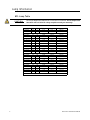
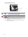
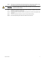
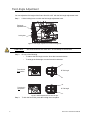
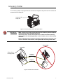
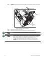
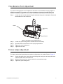
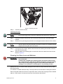
Source Four® Fresnel User Manual Rev A C o p y r i g h t © 2 0 1 1 E le c tr o n i c T h e a t r e C o n t r o l s , I n c . All Rights reserved. P r o d u c t in f o r m a t i on a n d s p e c i f i c a t i o n s s u bj e c t t o c h a n g e . P a r t N u m b e r : 7064M1200 R e v A R e le a s ed : 2 0 1 1 - 0 7 E T C pe r m i t s t h e r e p r o d u c t i o n o f m a t e r i a l s i n th i s m a n u a l o n l y f o r n o n - c o m m e r c i a l p u rp o s e s . A l l o t h e r r i g h ts a r e reserved by ETC. E T C i n t e n d s t h i s d o c u m e n t , w h e t h e r p r i n t ed o r e l e c tr o n i c , to b e p r o v id e d i n i t s e n ti r e t y . ET C ®, E m p h a s i s ®, E x p r e s s i o n ®, I n s i g h t ™ , Im a g i n e ™ , F o c u s ™ , E x p r e s s ™ , U n i s o n ®, O b s e s s i o n ™ I I, E T C N e t2 ™ , E D M X ™ , S o u r c e F o u r ®, R e v o l u t i o n ®, S en s o r ® a r e e i t h e r r e g i s t e r e d t ra d e m a r k s o r t r a d em a r k s o f E l e c t r o n ic T he a t r e C o n t r o l s , I n c . i n t h e U n i t e d S t a t e s a n d o t h e r c o u n tr i e s . A l l o t h e r t r a d em a r k s , b o t h m a r k e d a n d n o t m a r k e d , a r e th e p r o p e r t y o f t h e i r r e s p e c t i v e o w n e r s . Table of Contents Basic Assembly . . . . . . . . . . . . . . . . . . . . . . . . . . . . . . . . . . . . . . . . .1 Lamp Information . . . . . . . . . . . . . . . . . . . . . . . . . . . . . . . . . . . . . . . .2 HPL Lamp Table . . . . . . . . . . . . . . . . . . . . . . . . . . . . . . . . . . . . .2 Installing and Replacing the Lamp. . . . . . . . . . . . . . . . . . . . . . . .3 Field Angle Adjustment . . . . . . . . . . . . . . . . . . . . . . . . . . . . . . . . . . .6 Accessory Holder . . . . . . . . . . . . . . . . . . . . . . . . . . . . . . . . . . . . . . . .7 Yoke Balance Point Adjustment . . . . . . . . . . . . . . . . . . . . . . . . . . . . .9 Fixture Angle Adjustment . . . . . . . . . . . . . . . . . . . . . . . . . . . . . . . . . .9 Replacing the Lens. . . . . . . . . . . . . . . . . . . . . . . . . . . . . . . . . . . . . .10 Cleaning the Glass Lens and Reflector . . . . . . . . . . . . . . . . . . .11 i ii Basic Assembly Safety screen (CE markets only) Color frame holder Yoke Accessory holder door Field angle adjustment knob Fresnel lens Lamp door Lamp Lamp holder base Figure-1 Source Four Fresnel fixture components. WARNING: Please note the following safety warnings before use: Do not use this fixture with a damaged power lead. If the power lead (cordset) is damaged, it must be replaced. Do not mount the fixture on or near combustible surfaces. Do not operate the fixture without a lens installed. Always hang the fixture with the accessory door in the locked position. Basic Assembly 1 Lamp Informati on HPL Lamp Table CAUTION: Do not use lamps other than the HPL in Source Four fixtures. Use of lamps other than HPL will void UL/cUL safety compliance and your warranty. Lamp code Watts Volts Initial Lumen Color temp. Average rated life HPL 550/77* 550 77 16,170 3,250° 300 hours HPL 550/77X* 550 77 12,160 3,050° 2000 hours HPL 750/115 750 115 21,900 3,250°K 300 hours HPL 750/115X 750 115 16,400 3,050° 1500 hours HPL 575/115 575 115 16,520 3,250°K 300 hours HPL 575/115X 575 115 12,360 3,050°K 2000 hours HPL 375/115 375 115 10,540 3,250°K 300 hours HPL 375/115X 375 115 8,000 3,050°K 1000 hours HPL 750/120 750 120 21,900 3,250°K 300 hours HPL 750/120X 750 130 16,400 3,0500°K 1500 hours HPL 575/120 575 120 16,520 3,250°K 300 hours HPL 575/120X 575 120 12,360 3,050°K 2000 hours HPL 750/230 750 230 19,750 3,200°K 300 hours HPL 750/230X 750 230 15,600 3,050°K 1500 hours HPL 575/230 575 230 14,900 3,200°K 400 hours HPL 575/230X 575 230 11,780 3,050°K 1500 hours HPL 375/230X 375 230 7,250 3,000°K 1000 hours HPL 750/240 750 240 19,750 3,200°K 300 hours HPL 750/240X 750 240 15,600 3,050°K 1500 hours HPL 575/240 575 240 14,900 3,050°K 400 hours HPL 575/240X 575 240 11,780 3,050°K 1500 hours HPL 375/240X 375 240 7,250 3,000°K 1000 hours * To be used with ETC Dimmer Doubler™ 2 Source Four Fresnel User Manual Installing and Replacing the Lamp A lamp must be installed before you use the fixture. Lamp door latch Lamp door Figure-2 Lamp door on bottom of the fixture. Note: Verify that the HPL lamp you intend to install is suitable for your facility’s voltage; 115-, 120-, 230-, and 240-volt HPL lamps are available. See HPL Lamp Table, page 2. Operating HPL lamps above their rated voltage reduces lamp life and can cause premature lamp failure. WARNING: Unplug the fixture and allow it to cool down before attempting to change the lamp. Step 1: Disconnect power to the fixture before installing or replacing the lamp. Step 2: On the bottom of the fixture, turn the latch on the lamp door one-quarter turn and then open the door. Step 3: Remove the lamp holder assembly by turning the knurled knob counterclockwise to release the lamp socket assembly. Lamp Information 3 Step 4: Twist the lamp socket assembly counterclockwise one quarter turn and remove from the fixture. CAUTION: The socket assembly remains connected to the fixture by means of its electrical leads. Do pull or place undue stress on the wired assembly. Turn to remove Lamp holder assembly Figure-3 Remove lamp with quarter turn counterclockwise. Step 5: If replacing a lamp, carefully remove the old lamp from the lamp socket assembly. Step 6: Holding the new HPL lamp by the base, remove it from its box. CAUTION: Use caution when installing or replacing any lamp. When installing and replacing lamp, be sure to point the lamp away from your face and away from others before inserting it firmly into the assembly. This may prevent injuries if the lamp should break. CORRECT INCORRECT . Note: Step 7: 4 To avoid premature lamp failure, do not touch the lamp glass. If you do, clean it carefully with isopropyl alcohol and a clean lint-free cloth. Allow to dry before operation. Align the flat sides of the lamp base with the retention brackets on either side of the socket in the lamp holder assembly as shown in Figure-3. Source Four Fresnel User Manual Step 8: Push down on the lamp base until the lamp seats firmly. When properly installed, the top of the lamp’s base will be even with the top edges of the retention brackets. CAUTION: Step 9: Improperly installed lamps and lamp holder assemblies cause premature lamp failure and socket problems. Reinstall the lamp holder assembly into its socket in the fixture so that the arrow points towards the “unlock” icon on the socket. Step 10: Turn the lamp holder assembly clockwise one-quarter turn so that the arrow points to the “lock” icon. Step 11: Turn the knurled knob clockwise to secure the lamp holder assembly. Step 12: Close the lamp housing door and turn the latch to secure the door. Lamp Information 5 Field Angle Adjustment You can adjust the field angle of the fixture from 20 to 65° with the field angle adjustment knob. Step 1: Lift the locking lever to unlock the field angle adjustment knob. Field angle adjustment knob Locking lever Figure-4 Field angle adjustment knob and locking lever. CAUTION: Step 2: The focus knob does not rotate 360°. Do not attempt to exceed limit. Do one of the following. • To reduce the field angle, turn the focus dial counterclockwise. • To enlarge the field angle, turn the focus dial clockwise. Focus knob in flood position 65° field angle Focus knob in spot position 20° field angle Figure-5 Field Adjustment from flood to spot. Step 3: 6 To lock the focus dial, press the locking lever into place. Source Four Fresnel User Manual Accessory Holder The accessory holder is equipped with two slots and a locking door that prevents color frames and accessories from falling out. Accessory holder locking door Figure-6 Accessory holder door in the open position. . WARNING: Make sure all color frames and accessories are locked in position with the accessory door before hanging the fixture. Accessories such as barn doors and color scrollers must be secured by safety cable to the mounting position, such as batten, truss, or other secure structure. Fixture should never be oriented so that the weight of the accessories, such as color scrollers or barn doors, rests against the accessory holder door. Unacceptable Acceptable Safety cables to mounting position Accessory holder door Accessory Figure-7 Fixture with accessories. Accessory Holder 7 Step 1: Release the accessory holder door by pressing in on the latches located on each side of the door. Latch Lift front to open Latch Accessory slots Figure-8 Accessory holder door releases. Step 2: Insert the color frame or accessory. Step 3: Press down on the two accessory door latches to lock the door in place. Note: Use only color frames or accessories with a 7.5 inch mounting flange. Note: The performance of saturated colors may be less than desirable in any theatrical lighting fixture, especially when equipped with a 750w lamp. For best results, always use high-quality color media rated for high-temperature use. A variety of heat shield products is also available from many color media manufacturers. Follow the manufacturer’s instructions for the use of these products. 8 Source Four Fresnel User Manual Yoke Balance Point Adjustment The yoke mounting position can be adjusted on the fixture to accommodate varying weights of different accessories. For example, move the yoke balance point forward (toward the lens) to balance the additional weight of a color scroller and barndoor assembly in the accessory slot. Step 1: Loosen the nuts on both sides of the yoke assembly, being sure to steady the fixture with the handle on the rear of the unit. Handle Yoke locking knob Locking nut Figure-9 Yoke balance and angle adjustment. Step 2: Loosen the yoke locking knob so that the fixture moves freely. Step 3: Slide the fixture back and forth until it is properly balanced. Step 4: Tighten the yoke locking knob. Step 5: Tighten the two nuts. Fixture Angle Adjustment The fixture can be tilted up and down to position the light where it is needed. Refer to Figure-9. Step 1: On the side of the yoke, loosen the yoke locking knob, being sure to steady the fixture with the handle on the rear of the unit. Step 2: With the fixture turned on, use the handle tilt it to the desired angle. Step 3: Tighten the yoke locking knob. Yoke Balance Point Adjustment 9 Replaci ng the Lens Replace the lens if it becomes cracked or badly scratched. CAUTION: Never operate the fixture without a lens in place. WARNING: Unplug the fixture and allow it to cool down before attempting to change a lens. Removing the lens Step 1: Place the fixture on a flat, stable work surface. Do Not remove or install the lens with fixture hanging. Step 2: Tilt the front of the fixture down at least 45°. Step 3: Use a flat-blade screwdriver to slide the two plastic lens retaining clips on each side of the lens outward to release the lens. Figure-10 Lens retaining clip. Step 4: 10 Allow the top of the lens to drop forward from under the clips while using your hand to prevent the lens from falling. Source Four Fresnel User Manual Figure-11 Removing the lens. Step 5: Carefully remove the lens. Installing the lens Note: Do not leave finger prints on the lens. Handle the lens with a soft, clean cloth. Step 1: Position the fixture with the front of the unit (lens side) facing you, and tilted slightly upward. Step 2: Hold the lens by the edge and position it so the stepped side faces the front of the fixture. Note: The lens will not fit properly and will not function correctly if it is installed with the stepped side facing the rear of the fixture. Step 3: From the top of the fixture, slide the lens into the lens retaining slot and then rotate the top of the lens into place. Step 4: Slide the plastic lens retaining clips on each side of the lens inward to secure the lens. Refer to Figure-10. Cleaning the Glass Lens and Reflector WARNING: Do not use ammonia-based or other harsh commercial cleaners. Clean lens only as directed. Commercially available glass cleaning agents should be avoided as they may contain ammonia, other harsh chemical detergents or abrasive agents. These cleaners may damage the glass surface and the Anti-Reflective coatings. Do not immerse or soak the glass in any cleaning solution. Replace the lens if it contains visible damage such as cracks or deep scratches that may impair their effectiveness. The reflector is located behind the lamp. The lamp must be removed before cleaning the reflector. Remove dust with a blast of oil-free air or wipe with a clean, lint-free cloth. Isopropyl alcohol, distilled water or a 50% mixture of each can be used to clean the lens and reflector. Replacing the Lens 11 Corporate Headquarters 3031 Pleasant View Road, P.O. Box 620979, Middleton, Wisconsin 53562-0979 USA Tel +608 831 4116 Fax +608 836 1736 London, UK Unit 26-28, Victoria Industrial Estate, Victoria Road, London W3 6UU, UK Tel +44 (0)20 8896 1000 Fax +44 (0)20 8896 2000 Rome, IT Via Pieve Torina, 48, 00156 Rome, Italy Tel +39 (06) 32 111 683 Fax +44 (0) 20 8752 8486 Holzkirchen, DE Ohmstrasse 3, 83607 Holzkirchen, Germany Tel +49 (80 24) 47 00-0 Fax +49 (80 24) 47 00-3 00 Hong Kong Rm 1801, 18/F, Tower 1 Phase 1, Enterprise Square, 9 Sheung Yuet Road, Kowloon Bay, Kowloon, Hong Kong Tel +852 2799 1220 Fax +852 2799 9325 Service: (Americas) [email protected] (UK) [email protected] (DE) [email protected] (Asia) [email protected] Web: www.etcconnect.com Copyright © 2011 ETC. All Rights Reserved. Product information and specifications subject to change. 7064M1200 Rev A Released 2011-07