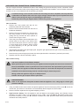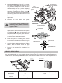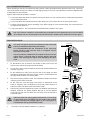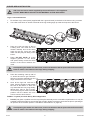
1
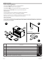
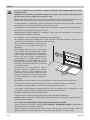
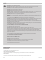
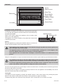
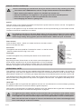
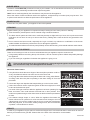
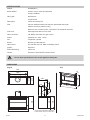
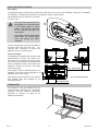
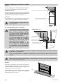
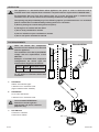
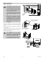
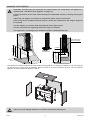
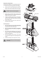
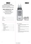
Operation & Installation Manual
RF800
This appliance shall be installed in accordance with:
• Manufacturer’s Installation Instructions
• Current AS/NZS 5601 AS/NZS 3000
• Local Regulations and Municipal Building Codes including local OH&S requirements
This appliance must be installed, maintained and removed by an Authorised Person.
For continued safety of this appliance it must be installed and maintained in
accordance with the manufacturers instructions.
All Rinnai gas products
are A.G.A. certified.
Congratulations on the purchase of your RF800 Decorative Gas Log Effect appliance
We trust you will have many years of enjoyment from your purchase.
THIS MANUAL CONTAINS IMPORTANT INFORMATION. FOR SAFETY PLEASE READ
CAREFULLY BEFORE PROCEEDING WITH ASSEMBLY, INSTALLATION AND OPERATION
OF YOUR NEW FLAME FIRE AND GAIN A FULL UNDERSTANDING OF THE APPLIANCE.
Rinnai
i
RF800 OIM
OPERATION TABLE OF CONTENTS
Before You Start
2
Safety3
Safety Devices
4
Features5
Control Panel Operation
5
Remote Control Operation
6
Operational Safety
6
Burner Media
7
Power Failure
7
Cleaning7
When to call for Service
7
Service7
Installation Table of Contents
9
Contacts26
Rinnai
1
RF800 OIM
BEFORE YOU START
INSTALLATION REQUIREMENTS
This appliance MUST BE installed by an authorised person.
The installation MUST conform to local regulations.
The installation MUST also comply with the instructions supplied by Rinnai.
Service and removal MUST BE carried out by an authorised person.
CERTIFICATION
The Rinnai RF800 has been certified by the Australian Gas Association.
The Certification Number is shown on the appliance dataplate.
No parts or functions are to be modified or permanently removed from the heater.
Please keep these instructions in a safe place for future reference.
CARTON CONTENTS
The components for RF800 heater are supplied in separate cartons, the following table lists which components are
in each carton. Ensure that the components listed for the installation method being installed are present before
proceeding with the installation.
A
B
1
2
6
5
7
(3 sided trim shown)
3
4
Item
8
Description
1
Rinnai RF800 gas fire engine
2
Side reflector panels
3
Remote control (batteries supplied)
4
This operation and installation manual
5
Gas connection kit: 200mm 3/8 Flexi tube with plug and 3/8” - 1/2” reducing flare connector
6
Coal location rail (not used for pebbles or crystal installations)
7
Trim & hangers - 3 or 4 sided / Black or Stainless Steel
8
Burner media - Logs and Coals or Pebbles *
C
Carton
A
B
C
●
●
●
●
●
●
●
●
* Log and coal set includes; 31 coals, 2 logs, 3 twigs, approx 120gms of granules - all parts are ceramic.
Rinnai
2
RF800 OIM
SAFETY
WARNING
DO NOT OPERATE THIS APPLIANCE WITHOUT READING AND UNDERSTANDING THESE
INSTRUCTIONS.
Taking time to familiarise yourself with the appliance’s features and operation will allow you to
get the most out of your appliance for years to come.
Please keep these instructions for future reference. Failure to comply with these instructions could
result in a fire or explosion, which could cause serious injury, death or property damage.
Improper installation, adjustments, service or maintenance can cause serious injury, death or property
damage. Such work must be performed by authorised personnel.
The appliance must be installed in accordance with the local gas and electrical authority regulations.
Flue terminal must always vent directly to outdoors.
DO NOT extend the flue vertically or horizontally in ways other than prescribed in the appliance
manufacturers’ installation instructions.
For information on gas consumption, see data plate on the appliance.
This appliance must not be installed where curtains or other combustible materials could come into
contact with it. In some cases curtains may need restraining.
When considering installation ensure minimum
clearances as in the adjacent drawing are
adhered to:
m Mi
in
0m
m
n
M
m
m
00
10
This appliance is not intended for use by
persons (including children) with reduced
physical, sensory or mental capabilities or lack
of experience and knowledge, unless they have
been given supervision or instruction concerning
use of the appliance by a person responsible for
their safety.
300m
75
Heat radiating from the front of this heater
may over time affect the appearance of some
materials used for flooring such as carpet, vinyl,
cork or timber. This effect may be amplified if
the air in the room contains contaminants like
cooking vapours or cigarette smoke. To avoid
this possibility, it is recommended that a mat or
similar protective sheet be placed in front of the
appliance, extending at least 750 mm in front of
the appliance fascia.
The appliance is not intended for use by young children or infirm persons without supervision.
Young Children must be supervised when in the vicinity of this heater while it is in operation.
For protection of young children or the infirm a secondary guard is required.
If the supply cord is damaged or requires replacing, it must be replaced by the manufacturer or the
manufacturer’s agent or similarly qualified person in order to avoid a hazard.
DO NOT connect to an LPG Gas cylinder indoors.
A dedicated 240 V earthed 10 Amp power point must be used with this appliance.
DO NOT modify this appliance. Modifying from original specifications may create a dangerous situation
and will void your warranty.
ONLY THE FLUE COMPONENTS SPECIFIED BY RINNAI MUST BE USED.
Unpack the heater and check for damage. DO NOT INSTALL A DAMAGED HEATER. If the heater is
damaged, contact your supplier for advice.
Before installing the heater, check the label for the correct gas type (refer rating plate, inside the
appliance). Refer to local gas authority for confirmation of the gas type if you are in doubt.
Rinnai
3
RF800 OIM
SAFETY
DO NOT sit or lean against the heater.
IMPORTANT
DO NOT allow children or elderly persons to sleep in the warm air discharge from the heater.
DO NOT post or allow children to post articles into the louvres of the heater.
DO NOT cover or place articles on this heater.
DO NOT place articles in front of the louvres.
DO NOT operate / install this heater in areas where painting is taking place, or in places such as
hairdressing salons, where there may be fluff and dust, and where aerosols are used.
DO NOT place articles on or against this appliance.
DO NOT use or store flammable materials near this appliance. Keep flammable materials away from
heater.
Combustible materials MUST NOT be placed where the heater could ignite them.
DO NOT spray aerosols in the vicinity of this appliance while it is in operation. Most aerosols contain
flammable substances which can be a hazard if used near this appliance when it is in use.
DO NOT use power boards or double adaptors to operate this appliance. The heater MUST NOT be
located below a power socket-outlet.
DO NOT place containers of liquid on top of the heater. Water spillage can cause extensive damage
to the appliance and create an electrocution hazard.
DO NOT CONNECT TO AN LPG GAS CYLINDER INDOORS.
Turn the heater ‘OFF’ when not in use.
DO NOT unplug the heater while it is in operation or while the fan is still cycling.
When the heater is operated for the first time or after long periods of non use a slight odour may be
emitted, this is normal. However if odours persist switch ‘OFF’ the appliance and contact Rinnai.
Appliances incorporating a live fuel effect and designed to operate with luminous flames, may exhibit
slight carbon deposits.
This is primarily a decorative appliance and has not been designed as a space heater.
NOT INTENDED FOR FIREPLACE INSERT
WHAT TO DO IF YOU SMELL GAS
DO NOT try to light any appliances.
DO NOT touch any electrical switches: do not use any phone in your building
Immediately close the shut-off valve at the gas meter or bottles
Call an authorised service technician
SAFETY DEVICES
Electrical Fuse:
The electrical circuits are protected by a fuse.
Flame Failure Sensing System:
This device automatically cuts off the gas supply to the heater in the event of a flame failure.
Power Failure:
In the event of a power failure or power cut, the gas valves will automatically close.
Rinnai
4
RF800 OIM
FEATURES
Hot Air
Outlet Louvre
Outer Trim
Reflectors
Burner Media
(Logs, Coals/
Pebbles/ Glass)
Front Panel
Control Panel
Air Intake
CONTROL PANEL OPERATION
To operate your appliance for the first time, ensure that the gas supply
is on and that the appliance has been tested and commissioned by
an authorised installer.
Switch on the power supply to the appliance (This is usually a wall
switch near to the appliance).
ON/OFF Button
Operation LED
The appliance can now be started by using either the Control Panel
or the Remote Control.
Ignition
Start the appliance by pressing the ON/OFF button for at least one
second until the red light on the control panel comes on.
NOTE
Remote Receiver Window
If the appliance has not been used for some time then the gas may take some time to ignite as the
gas in the pipes may need to purge.
The appliance will try to start for up to one minute before “locking out”. If this happens, then
press the ON/OFF button twice to re-set then re-start the appliance.
If the appliance has not started after 3 attempts, contact the installer or an authorised service
person.
Always run the appliance on high for at least a few minutes to ensure a quick warming up of the firebox and flue.
NOTE
The appliance will start on the same flame setting it was last used at unless the mains power
supply has been disrupted or disconnected, whereby the default flame setting is reset to low.
To ensure a high setting, during ignition press the flame control + button for up to 10 seconds
(refer to the remote control operation on page 6 for flame control details).
Once the Pilot has ignited, then gas will begin to flow to the main burner. The flame picture should be right across
the burner within about 10 seconds.
If the burner does not light or only lights part way across then turn the appliance off immediately and call an
authorised service technician for further advice.
Turning Off
The appliance can be stopped by pressing the ON/OFF button on the Control Panel or by pressing the power
button on the remote control (refer to the remote control operation on page 6 for details).
The flames may take a few seconds to fully extinguish. This is normal and is not a cause for concern.
Rinnai
5
RF800 OIM
REMOTE CONTROL OPERATION
NOTE
Here are a few things you should know about your remote control to keep it working at its best:
The remote uses 4 AAA batteries, and has a range of about 8 metres with fresh batteries.
When replacing the batteries, replace all 4, DO NOT mix old with new.
Remove the batteries if the appliance is not going to be used for extended periods.
Some fluorescent lights can affect the performance of the remote.
Avoid dropping the remote or getting it wet.
•
•
•
•
•
Ignition
Point the remote control towards the appliance and press the power button for at least 1 second. The appliance
will then commence the ignition sequence.
Always run the appliance on high for at least a few minutes to ensure a quick warming up of the firebox and flue.
The flame can then be turned down if so desired.
NOTE
The appliance will start on the same flame setting it was last used at unless the mains power
supply has been disrupted or disconnected, whereby the default flame setting is reset to low. To
ensure a high setting, during ignition press the flame control + button for up to 10 seconds.
Flame Control
Press the flame control + button to increase the fame or the flame control button to decrease the flame.
Fan Control
The appliance has a two speed fan. Press the fan control + or the fan control
- buttons to switch the fan to High, Low or Off.
Power
Turning Off
Flame
Control
To switch the appliance off, press the power button on the remote control.
Auto Off Timer
By pressing the auto off timer button on the remote control the appliance can
be set whilst in operation for a 30 minute delayed switch off. The red indicator
light on the front panel of the appliance will flash when this mode has been
activated. Pressing the auto timer button a second time will cancel this mode.
Fan
Control
Auto Off/
Cancel
OPERATIONAL SAFETY
This appliance is factory tested and the installation MUST BE tested by an authorised installer. You should not
experience any odour from your appliance other than initial burn off smell the first time it is used. Should any odour
persist after the initial burn in, turn off the gas supply and arrange for an authorised person to make a service call.
This appliance has a flame failure safety system which ensures that in the event of an ignition failure, gas supply
failure or flame being extinguished for any reason, the appliance will shut down. The appliance will attempt to restart automatically.
LOCK OUT
If the appliance fails to re-ignite then the appliance will “lock out” and will need to be re-set manually by pressing
the ON/OFF button twice to re-set and re-start the ignition sequence.
Wait at least 10 seconds before re-starting the appliance and if the appliance fails to ignite after 3 attempts then
turn off the power and refer to the trouble shooting section on page 22.
NOTE
This appliance burns with a real flame and as such there are considerations to be made to ensure
the safety of children and the infirm. In such circumstances a fire guard should be secured in front
of the appliance. Furniture and other objects must not be placed within 1 metre of the fireplace.
Make sure that the lower and upper air inlets are not blocked as this could cause damage to the
fan or cause the gas controls to overheat.
Rinnai
6
RF800 OIM
BURNER MEDIA
The burner media MUST BE positioned correctly by the installer. It is not intended that these are re-positioned by
the user. Incorrect positioning can affect heat output and ignition.
ONLY burner media supplied by the manufacturer may be used in this appliance.
Due to the nature of luminous flames used in this appliance, a slight build up of carbon (soot) may be seen. This
is quite normal and will not affect the performance of the appliance.
POWER FAILURE
In the event of a power failure, your appliance cannot be operated.
CLEANING
Regular cleaning of your appliance is important to keep it looking its best. Some points on cleaning:
•All of the exterior painted panels can be cleaned using household cleaners.
black interior panels and the burner media may develop a slight build up of soot, this is quite normal and
•The
might burn off over time. Do not try to remove the soot by rubbing with a cloth as this will only spread the soot
around.
not vacuum the burner media, especially the Log & coal bed, any reduction or modification of the burner
•Do
media installed can effect the performance and or damage the appliance.
•The stainless steel reflectors and front panel (if fitted) can be cleaned using a household stainless steel cleaner.
WHEN TO CALL FOR SERVICE
There are a few things to look out for that could indicate that your appliance requires a service call.
streaky flames are touching the top of the firebox, this can cause the paint to blister and possibly damage
•Ifthelong
appliance.
•If you can smell gas, regardless of whether the appliance is going or not.
NOTE
There can be a brief smell of gas as the appliance is going through the ignition sequence, however
this should soon stop once the appliance has started.
Abnormal Flame Pattern
•If the pilot flame looks abnormal. Signs of abnormal pilot operation could be:
A very short flame that does not reach across to the flame rod.
A very long flame that reaches far beyond the flame rod or long yellow flames.
A roaring noise when the pilot is operating or the flame “lifting off” from the
pilot head.
•If there are large soot deposits that keep building up on the burner media.
is excessive noise or explosive ignition as the burner lights, this could
•Ifbethere
due to blocked burner ports.
a smell of flue gas continues after the appliance has been operating for at
•Ifleast
10 minutes. This could indicate a blocked flue or other problem. This
smell is acceptable during the first few minutes as the flue heats up and starts
to draw.
the flames change shape or colour. When the appliance first starts the
•Ifflames
will tend to be quite blue for a few minutes but will change to a more
yellow/orange colour as the system heats up, this is normal, but if the flames
either stay very blue, or turn a dark , streaky orange colour, this could indicate
a problem. Contact Rinnai for advice.
SERVICE
In order for your appliance to give years of comfort and enjoyment, it is recommend that it is serviced on an annual
basis by a licensed service gas fitter. Please refer to the back of this manual for contact details.
Rinnai
7
RF800 OIM
This page is intentionally blank
Rinnai
8
RF800 OIM
INSTALLATION TABLE OF CONTENTS
Operation Table of Contents
1
Installation Safety
10
Specifications
11
Dimensions
11
Gas & Electrical Supplies 12
Clearances
12
Mantles, Surrounds, Recesses & Hearths
13
Ventilation
14
Flue Requirements
14
Engine Installation
15
Masonry Cavity Design
16
Appliance Gas Connection & Commissioning
18
Aeration Sleeve Details
19
Pilot Burner Performance
20
Trim Installation
20
Burner Media Installation
21
Final Checks
22
Trouble Shooting
22
Commissioning Checklist
22
Wiring Diagram
23
Installation Notes
24
Contacts26
Rinnai
9
RF800 OIM
INSTALLATION SAFETY
WARNING
This appliance must be installed by a suitably qualified person in accordance with local codes and
AS/NZS 5601
This is primarily a decorative appliance and has not been designed as a space heater
This appliance has been tested to AS 4558
DO NOT operate this appliance without reading and understanding these instructions first
This appliance is designed for installation into a timber framed construction and new or existing masonry
installations
NOT INTENDED FOR FIREPLACE INSERT
Only the approved flue componenets specified by Rinnai MUST BE used
This appliance must be installed into a well ventilated room in accordance with AS/NZS 5601
This appliance is designed for indoor installation only; NOT TO BE INSTALLED OUTDOORS
Rinnai is not responsible for incorrect or improper installations
All installations must be carried out by authorised personnel
Be sure to complete the installer details section of the user guide before signing off the installation
DO NOT place articles on or against this appliance
DO NOT store chemicals or flammable materials, or spray aerosols near this appliance
DO NOT operate with panels, covers or guards removed from this appliance
DO NOT modify this appliance
Rinnai10
RF800 OIM
SPECIFICATIONS
Models:RF800E(N/P)
Burner Media:
Ceramic Logs / Coals and Granules
Ceramic Pebbles
Gas Types:Natural Gas
Propane Gas
Description:
Indoor Decorative Fire
Flue:
200 mm stainless steel inner/ 250 mm galvanised steel outer
200mm Flexi liner (masonry only)
Minimum of 2.4 metres of flue, 3.6 metres if off-set bends are used
Flue Cowl: AGA Approved 200 mm Flue Cowl
Gas Connection:
3/8” BSPF Gas Flare onto gas control
Power: 230/240V a.c. 50hz, 1 Amp
Fan:Tangential; 2 speed
Burner: Bunsen type atmospheric
Gas Control: SIT 845 with SIT 579. DBC modulating control
Ignition:Electronic
Flame Monitoring:
Flame rod
Control:
Electronic control with IR remote control
NOTE
For all other specifications refer to the appliance data plate.
DIMENSIONS
Engine
Trim
870
15
378 *
605
410
375 **
800 **
230
583
552 **
600
900
910
* APPROXIMATE DEPENDS ON BENDS
** FOR MASONRY INSTALLATIONS ONLY
Rinnai11
RF800 OIM
GAS & ELECTRICAL SUPPLIES
Gas Supply
A suitable gas supply needs to be provided to the left hand rear corner of the installation cavity prior to installing
the appliance. The pipe sizing should be calculated to supply at least 40MJ/h
Allow sufficient pipe to make the connection
as shown right.
NOTE
The gas inlet access point for
this appliance is provided with
a set folding flaps to allow
piping with fittings attached
to be passed through for
connection.
For vermin control ensure that
these flaps are closed again
once the piping has been
installed.
Use the supplied gas connection kit (200mm
3/8 Flexi tube with plug and 3/8” - 1/2”
reducing flare connector) to connect the
appliance to the consumer piping.
Electrical Supply
350
155*
261* approximate
108
This supply is used to isolate all power from
appliance. The power cord is designed for a
230/240V AC 10 amp supply.
117
The appliance is supplied with a power lead
approximately 1.8m long. This needs to be
connected to an isolating wall socket within
the cavity and connected to an isolating wall
switch, preferably located to the right of the
appliance, facing into the room, not inside
the framing cavity.
Electrical connections must be in accordance
with AS/NZS 3000 and installed by an
authorised person.
* From finished wall lining
305 approximate
CLEARANCES
300m
m Mi
n
10
00
m
m
M
75
in
0m
m
The appliance must be installed with the
shown minimum clearances to combustible
materials. See also “Mantles, Surrounds,
Recesses & Hearths” on page 13 for
additional information.
Rinnai12
RF800 OIM
MANTLES, SURROUNDS, RECESSES & HEARTHS
Mantles
45°
A timber mantle may be installed above this appliance
but must be within the grey area as shown here.
X
Timber Surrounds
Mantle
MANTLE MUST NOT EXTEND BEYOND THIS AREA
X
As with mantles when a timber surround is to be fitted,
ensure it complies with minimum timber clearances
of 300mm above and 150mm to each side.
NOTE
* NOTE THAT SIDE CLEARANCES CAN BE
REDUCCED FROM 300MM TO 50MM
300*
If the appliance is to be installed into a recess the
recess must comply with the following limitations.
Wall
Recesses
The same limitations apply to the sides
of the appliance.
Top Trim
TV or Ornamentation Above The Heater
CAUTION
RECESS MUST NOT EXTEND
BEYOND THIS AREA
The installation of electrical appliances
above and in the vicinity of the heater
such as, but not limited to, Plasma
TV, LCD TV, Home Theatre Screens,
Speakers, etc must comply with their
manufacturers’ instructions.
It is the responsibility of the installer/
end-user to check the installation
instructions of these items and to
ensure the location is suitable.
FIREPROOF BOARD FOR
ANY WALL BELOW RECESS
45°
FIREPROOF BOARD FOR
MINIMUM HEIGHT OF 300 MM
This caution also extends to, but
is not limited to, ornaments such
as: Paintings, Prints, Photographs,
Tapestries, Mirrors, Stuffed Animals,
etc.
IDEA
NOTE
100
FIREPROOF BOARD OR OTHER
NON-COMBUSTIBLE MATERIAL
WALL
SIDE VIEW
TRIM
Use either a shelf or mantle below the TV or ornament or alternately you can construct a recess
to mount TV or ornament on.
Check the manufacturers installation instructions for these items and ensure the recess is
suitable.
Rinnai does not take any responsibility for any damage occurring to any items installed above
and in the vicinity of the heater.
Hearths
Although a solid hearth is not required, if the appliance
is to be installed within 300 mm of the floor, it is
recommended that protection is given to any flooring
surface directly in front of the unit.
The appliance produces a large amount of radiant
heat and this might cause damage to flooring and
furnishings that are too close.
0
30
Rinnai13
RF800 OIM
VENTILATION
IMPORTANT
This appliance is a decorative flame effect appliance, the space or room in which the unit is
installed must have adequate fixed ventilation compliant with the requirements of AS/NZS 5601.
For Decorative Gas Log Fires this requires that one or more openings with a combined free
ventilation area of not less than 314 cm² shall be provided for each appliance.
The opening may be provided by any of the following options, provided that there is a ventilation
path to outside that is unobstructed by building material or insulation:
a) Directly through an outside wall (preferred option).
b) Through to an outside wall but offset.
c) Into a cavity ventilated to outside.
d) Into an underfloor space ventilated to outside.
e) Into a roof space ventilated to outside.
FLUE REQUIREMENTS
IMPORTANT
ONLY the Rinnai flue components
described in this manual are to be used
with this appliance.
Direct
Offset
A
A
The installation of the flue system MUST
comply with the requirements of AS/
NZS 5601.
A
Examples of available flue component
configurations are shown right, the
minimum flue heights are as follows:
Direct
Offset
Extended Offset
2.4m
3.6m*
3.6m*
Extended Offset
A
A
B
A
B
B
B
* Only 1 x RFBEND200 can be used
on any Offset or Extended Offset flue
installation.
A
RFBEND200
2x 45° twin skin bends ø 200mm inner / ø 250mm outer
NOTE
The assembled RFBEND200
dimensions shown right are
approximate and are for reference
purposes only.
C. RFCOWL200
Connection ø 200mm
Cowl outer ø 350mm
Rinnai14
35
45°
B
70
B.
RFPIPE200
900mm twin skin flue pipe ø 200mm inner / ø 250mm outer
(approx 855mm when installed)
357
A.
148
C
Dimensions are approximate
and are for reference purposes only.
RF800 OIM
ENGINE INSTALLATION
Timber Cavity Design
The appliance and flue need to be
installed before the wall can be lined!
DO NOT INSTALL THIS
LINTEL UNTIL ENGINE AND
FLUE ARE INSTALLED
It is recommended that the cavity lintel
is left off until the flue and engine have
been installed (Allow approx 1200mm
clearance above the engine).
Remember that both gas and electricity
are required within the cavity (see,
“Gas & Electrical Supplies” on page
12).
When engine installation is complete,
the fitting of cardboard from the
packaging material to the front flanges
of the appliance with some low-tac
masking tape will help to protect the
appliance from dust, paint, etc. of
subsequent construction drawing into
the appliance.
595~600
IMPORTANT
25mm MIN CLEARANCE BETWEEN FLUE AND COMBUSTIBLES
880~
900
M
U ITY
IM V
IN CA
M F
m O
5m TH
3
4 EP
D
368mm FROM FINISHED WALL FACE
FIX TO APPLIANCE WITH SCREWS
OR RIVITS (NOT SUPPLIED)
Secure the appliance to framing using strapping
provided with appropriate fixings (not supplied) as
shown.
It is recommended that the appliance be installed on
a solid platform.
If this is not possible then there must be support
provided at the front and back of the cavity - no
further back than 368mm.
NOTE
FIXING STRAP
If the appliance is to be installed
with a hearth, either on the floor or
cantilevered, it is important that the
finished top of the hearth is flush with
the floor of the installation cavity.
For the best finish, allow for the hearth
to fit under the engine by 5~10 mm.
5~10mm FRONT OF
FIRE TO EDGE OF
HEARTH
CAVITY BASE
HEARTH
HEARTH
SUPPORT
Rinnai15
WALL BOARD
RF800 OIM
MASONRY CAVITY DESIGN
Remember that both gas and electricity are required within the cavity before the appliance is
installed (see, “Gas & Electrical Supplies” on page 12).
NOTE
These instructions are for either new masonry/non combustible cavities or existing masonry fire
places.
A flexi flue and adaptor is available for installations where access is restricted.
If the cavity can be completed after the engine and flue are installed then the adaptor might not
be required.
The flue adaptor can also be used with rigid flue where space allows.
The flue should be self supporting before the engine is installed.
This appliance is not designed for installation without a dedicated flue liner.
200 SINGLE SKIN
FLEXI FLUE LINER
~90
0
FLEXI FLUE
AND ADAPTOR
~90
0
575~595
805
400 MIN
552 TO UNDERSIDE
OF SPIGOT
370 MIN
555~595
575~595
380
229
This appliance consists of a firebox and removable insulating panels. For masonry installations only, these panels
can be removed if cavity space is restricted. Remove as few or as many panels as required. The more panels
retained, the more efficient the appliance will be.
IMPORTANT
Take care not to damage the power cord when removing the back panel!
Rinnai16
RF800 OIM
Preparation of the Engine
If the flexi flue adaptor is to be used then there are
modifications that need to be made to the engine.
1.
Remove the top insulating panel and insulation.
2.
Remove the 4 screws holding the twin skin flue
spigot in place and carefully remove the spigot.
IMPORTANT
DO NOT remove the white gasket.
3.
Remove the six screws down the side of the
spigot and attach the two spigot rails that are
supplied with the flexi flue spigot
4.
If the top insulation panel is to be used, then
it must be cut to allow the spigot to transition
down the rails. Each panel will end up being
about 250mm wide
5.
Remove the two knock-outs in the centre of the
top flange of the engine
INSULATION
AND COVER
SPIGOT RAILS
SPIGOT GASKET
250
SPIGOT KNOCK OUTS
Installing Engine
1.
Place the engine onto the hearth and carefully
line up the gas supply pipe with the hole in the
back left hand corner of the engine
2.
Make sure that the power supply cord is passed
through the cavity for connection by a registered
electrician.
3.
Line the flue spigot adaptor up with the guide
rails on the top of the engine and push the
engine in. Take care not to roll the spigot gasket
as the engine slides in!
4.
Once the engine is fully home, use screws
to hold the flue spigot to the top flange of the
engine
5.
Fix the front flange of the engine to the cavity.
NOTE
SPIGOT GASKET
It is not necessary to seal the engine to
the cavity.
SPIGOT FIXING
ENGINE FIXING
Rinnai17
RF800 OIM
APPLIANCE GAS CONNECTION & COMMISSIONING
Once the engine has been installed and fixed to the building the gas and electricity can be connected. Some
installers elect to leave this until the decorating has been completed and the installation can be finished, remember
that the trim can not be attached until the wall lining is finished.
CAUTION
If commissioning is to be carried out after the decorating has been completed, leave a protective
cardboard cover taped to the front of the engine using a low-tack tape to prevent plaster dust and
debris from entering the engine and damaging the paint work.
Isolate the power and gas supplies before commencing work on the appliance.
Gas Connection
1.
Remove the front panels and strip all the
protective plastic film from this item.
2.
Remove the Air Diverter Panel from the front of
the Burner Assembly.
3.
Remove the burner assembly by removing the
two fixing screws in front of the burner and
pulling the tray forward and then upwards to
remove from the gas control.
4.
There may be aeration sleeves attached to the
venturi tubes on the back of the burner, take
care not to lose these, there is a chart on page
19 that shows which aeration sleeve should
be used depending on the gas and burner
media being used.
BURNER FIXING
SCREWS
BURNER
ASSEMBLY
GAS CONTROL
FIXING SCREWS
CONTROL
PANEL
AIR DIVERTER
PANEL
CONTROL
LEAD
5.
After bending and flaring the gas supply pipe, purge the gas pipe and fix the gas control assembly back in
place and connect the gas.
6.
Reconnect the power and gas (reconnect the control panel and fan connection if previously removed).
7.
Replace and fix the burner assembly in place.
Gas Commissioning
240 VOLTS, RISK OF ELECTRICAL SHOCK!
WARNING
When performing the commissioning, the appliance electrical power will need to be connected.
Exercise CAUTION as there is potential for electric shock from the exposed wiring and circuitry.
DO NOT leave the appliance unattended when power is connected and the panels are removed.
Installation and commissioning must be carried out by an authorised person.
Wiring inside this appliance may be at 240V potential.
DO NOT test for gas escapes with an open flame.
GAS PRESSURES
NOTE
Refer to the appliance data plate located inside the appliance on a swing tag for correct gas
pressure settings.
1.
Using a suitable screw driver loosen the captive Appliance Test Point Pressure (ATPP) screw D and fit the
manometer, (an electronic manometer is recommended). Refer images for ATPP location.
2.
Remove the dust cap C from the regulator adjusting screws.
3.
High Pressure Setting: Turn the appliance ‘ON’ and adjust to the highest setting, see “Remote Control
Operation” on page 6. Use a 10 mm spanner to turn nut A , lock screw B with appropriate screw driver
to prevent it turning. Turning nut A clockwise increases the outlet pressure whilst turning anti-clockwise
decreases the outlet pressure.
Rinnai18
RF800 OIM
4.
Low Pressure Setting: Turn ‘OFF’ the power
to the POV by separating the connector of the
two yellow wires that power the POV. The POV
will automatically default to ‘Low Pressure’
operation. Keep the high pressure adjusting
nut stationary using a 10 mm spanner. Use an
appropriate screwdriver for setting screw B.
Turning clockwise increases the outlet pressure
whilst turning anticlockwise decreases the outlet
pressure.
5.
Replace the dust cap C after pressure
adjustments.
6.
Reconnect the POV Yellow wires power
connection.
WARNING
To ensure the correct operation of the
modulating valve (POV) it is necessary
that the dust Cap C is returned to its
original location.
7.
After re-checking the pressures, turn the
appliance ‘OFF’, remove manometer and replace
the ATPP screw D. Check all connections and
test points for leaks using soapy water solutions.
8.
Turn the appliance ‘ON’ and ‘OFF’ a few times
to confirm correct ignition and operation.
9.
During the initial burn in period, some smoke
and smell may be emitted. The appliance should
be run with both the flame and fan set to high in
a well ventilated room until these dissipate.
D
APPLIANCE OUTLET
TEST POINT PRESSURE
INLET
TEST POINT
C CAP
GAS
OUTLET
GAS CONTROL
AND IGNITION
PACK ASSEMBLY
A
B
HIGH PRESSURE
ADJUSTING NUT
LOW PRESSURE
ADJUSTING SCREW
A
B
ON/OFF BUTTON
FLAME UP BUTTON
10. Check the flame pattern, see Abnormal Flame
Pattern”, “When to call for Service” on page
7.
FAN UP BUTTON
11. Proceed to the section “Trim Installation” on
page 20
OFF TIMER BUTTON
FLAME DOWN BUTTON
FAN DOWN BUTTON
AERATION SLEEVE DETAILS
It is important that the correct aeration sleeves are used for each gas type and burner media. The appliance should
have been supplied with the correct aeration sleeves. If the appliance is to be set up on propane with pebbles or
crystals then the sleeves supplied with the burner media need to be fitted. Refer to the notes supplied with the
burner media and the chart below for more information.
Aeration
Sleeves
Identification
groove
Gas Type
Burner Media
No. of ID Grooves on Sleeve (Depth of Sleeve)
Natural Gas
All
None
Logs/Coals
No Sleeves
Pebbles or Crystals
1
Propane
Rinnai19
RF800 OIM
PILOT BURNER PERFORMANCE
When operating at its best, the pilot burner will produce a sharp blue flame with a light blue inner cone. This inner
cone should reach across to the flame rod and slightly beyond. The size of the pilot flame cannot be adjusted and
is dependant on inlet pressure.
Signs of abnormal pilot operation could be:
short flame that does not reach across to the flame rod. This could be due to a reduced inlet pressure
• Aorvery
a blocked pilot injector.
• A very long flame that reaches far beyond the flame rod. This could be due an incorrect pilot injector.
noise when the pilot is operating or the flame “lifting off” from the pilot head. This could be due to
• Atooroaring
high an inlet pressure.
• Long yellow flames. This could be due to blocked primary aeration of the pilot.
NOTE
Any one of these conditions could affect the performance of the appliance (such as soot build
up on flame rod, etc) and should not be left unresolved. Contact your authorised service agent .
TRIM INSTALLATION
NOTE
The outer trim panel cannot be installed until the wall board
has been attached and finished (decorated)
REFLECTOR
EARTHING SCREW
It is recommended that the installation of the trims and
burner media is left until the room is complete and all
decoration is finished.
2
1
Leave a protective cardboard cover taped to the front of the
engine using a low-tack tape to prevent plaster dust and
debris from entering the engine and damaging the paint
work.
1.
Fit the Minimal Trim so that the two hooks in each end fit over the
screws in the side of the engine as shown below.
2.
Fix the trim in place using an earthing screw (with serrated washer) in
one end of the trim.
3.
Fit the reflectors by fitting over the front trim at an angle and then
standing up against the side of the engine. There is a catch above the
top edge of the reflector to hold it in place.
4.
Pull the two spring loaded Lower Trim Retainers forward and down
until they lock in place as shown.
5.
Fit the outer trim over the Upper Trim Hooks. If adjustment of the
hooks is required, use a screwdriver to prise the hooks forward, or
push them back until the trim fits flush with the wall.
6.
Hold the leg of the trim against the Lower Trim Retainer and push the
Retainer outwards, the spring Retainer will pull up into the bracket
on the back of the trim and back into the cavity once the bracket is
horizontal again.
WARNING
7.
Take care when the spring grabs that the trim is not resting
on the hearth as it could bite into the surface and scratch
it. Either hold the trim slightly higher or use a thin piece of
card between the leg end and the hearth.
MINIMAL
TRIM
REFLECTOR
RETAINER
REFLECTOR
UPPER
TRIM
HOOK
3
2
1
LOWER
TRIM
RETAINER
Proceed to “Burner Media Installation” on page 21
Rinnai20
RF800 OIM
BURNER MEDIA INSTALLATION
ONLY use the burner media supplied by the manufacturer in this appliance.
WARNING
DO NOT BURN WOOD OR ANY OTHER MATERIAL IN THIS APPLIANCE.
Logs, Coals and Granules
1.
Fit the Rear Log Locator panel (supplied with the Logs and Coals) to the back of the burner using 4 screws.
2.
Use a flat screw driver or similar to bend all of the log locating tags up wards until square to the burner.
3.
Place one coal onto each of the 23
Locating Pins. The coals are to be
located centrally and at the same
angle as the tag. Push the coals
down until they are just sitting on the
burner.
4.
Place, DO NOT POUR, all of the
supplied granules on the burner
and spread evenly across the entire
surface of the burner between the
coals.
IMPORTANT
Avoid pouring the media over the burner, as this can block the burner ports with the fine dust that
tends to settle in the bottom of the bags during shipping.
5.
Place the remaining coals (a total of
31 should be used to get maximum
efficiency) and the supplied logs and
twigs over the first row of coals.
6.
Once all the logs and coals are in
place, light the appliance and assess
the look of the flames. If there are
any areas that have very long streaky
flames then, using a pair of tongs,
move the top logs or coals to another
position until the flames are more
even across the whole burner.
Pebbles / Crystals (Crushed Glass), Where Applicable
1.
DO NOT pile glass or pebbles over the top of the pilot assembly as this could affect it performance. It may be
possible to build the media up around the pilot to hide it slightly but always check that the pilot is operating at
its optimum when finished. (Refer to “Pilot Burner Performance” on page 20).
IMPORTANT
Avoid pouring the media over the burner, as this can block the burner ports with the fine dust that
tends to settle in the bottom of the bags during shipping.
Rinnai21
RF800 OIM
FINAL CHECKS
Check that the appliance operates properly in all modes (high & low gas rates, fan high & low.) and make sure that
all the supplied parts are used and properly installed.
It is important that the customer is fully aware of how to operate the appliance properly and safely. Advise the
customer to fully read the operation sections of this manual to understand how to get the best out of their appliance.
Advise the customer of the need for regular servicing in order to maintain the warranty.
Complete the Commissioning Checklist.
TROUBLE SHOOTING
Symptom
Front panel ON/OFF
button does not work (no
spark noise)
Remote control ON/OFF
button does not work
(no spark noise), yet
the front panel ON/OFF
button does work
Ignition is sparking then
locks out
Sparking continues,
after pilot flame ignites
Possible Cause(s)
Mains Power Disconnected
Gas Control Locked Out
Faulty Control Mechanism
ON/OFF button not held for 1 second
Flat Batteries
Signal interference
Faulty remote control or receiver
Gas Control Locked Out
ON/OFF button not held for 1 second
Air in gas supply
Gas supply turned off or empty
Faulty flame rod
Dirty gas in cylinder (LPG/Propane)
Corrective Action(s)
Check mains supply & isolating switch
Press ON/OFF button twice to reset*
Service Call
Hold ON/OFF button for at least 1 second
Replace Batteries
Move to another part of the room
Service Call
Press ON/OFF button twice to reset*
Hold ON/OFF button for at least 1 second
Purge gas supply*
Turn on gas supply or change gas cylinder
Service Call
Replace or change over gas cylinder
Faulty gas control
Service Call
Gas supply turned off or empty
Mains power disconnected
Accidental operation of remote control
Flat batteries in remote control
Faulty remote control or receiver
Faulty fan or wiring
Turn on gas supply or change gas cylinder
Check mains supply & isolating switch
Check location of remote control
Replace Batteries
Service Call
Service Call
Pilot ignites, yet main
flame does not
Flame goes out
Fan does not operate
*If the appliance fails to ignite after three (3) attempts, turn off the power and gas if possible and arrange for a
service call or contact the installer if the unit is newly installed.
COMMISSIONING CHECKLIST
To be completed by the installer
Serial Number ___________________________________________________________
1.
Is the appliance positioned in a suitable location with regards to clearances?
2.
Is the unit fixed in location?
3.
Is the burn media installed and positioned correctly?
4.
Have all gas connections been checked for leaks using a soapy water solution?
5.
Have you instructed the owner of the correct operation of this appliance before leaving?
6.
Have you left the operating instructions with the owner?
7.
Have you removed all PVC plastic coating material?
NO
YES
Ensure all PVC plastic coating material is removed before operating the unit.
WARNING
If you have answered NO to any of the above questions you MUST NOT allow the appliance to be
operated until the item has been rectified.
Rinnai22
RF800 OIM
WH
BLK
YL
RD
BLU
BRN
GR
OR
13
14
Rinnai23
1 GAS CONTROL 12
(SIT845 with 0.579.506 DBC)
13/14
GAS CONTROL 12 PIN PLUG
1 - EMPTY
2 - EMPTY
3 - EMPTY
4 - EMPTY
5 - BLK
6 - BLK
7 - BLK
8 - EMPTY
9 - EMPTY
10 - BRN
11 - BLU
12 - GR
SPARK
FLAME
SPARK
CAT 5 CABLE
TO RECEIVER
OR
GR
PILOT
MOD 2
MOD 1
WH (HT LEAD)
YL
BRN
YL
LOW
WH
MED
RD
HIGH
CONTROL BOX
(Millenium)
NEUTRAL
NEUTRAL
BLU
MAINS IN
230/240 V a.c.
50 Hz
10 AMP
4
3
2
1
BLU
WH
RD
GR
3 AMP
FUSE
1
2
BLU
BLU
BRN
BRN
COLOUR
WHITE
BLACK
YELLOW
RED
BLUE
BROWN
GREEN / YELLOW
ORANGE
WIRING DIAGRAM
RF800 OIM
GR
ACTIVE
INSTALLATION NOTES
Write any comments on the installation here and leave with the owner for future reference.
Rinnai24
RF800 OIM
This page is intentionally blank
Rinnai25
RF800 OIM
CONTACTS
Australia Pty. Ltd.
ABN 74 005 138 769
Head Office
100 Atlantic Drive,
Keysborough, Victoria 3173
Tel: (03) 9271 6625
Fax: (03) 9271 6622
Internet: www.rinnai.com.au E-mail: [email protected]
National Help Line
Tel: 1300 555 545*
Fax: 1300 555 655*
*Cost of a local call higher from mobile or public phones.
Hot Water Service Line
Tel: 1800 000 340
P.O. Box 460
Braeside, Victoria 3195
Rinnai has a Service and Spare Parts network with personnel who are fully trained
and equipped to give the best service on your Rinnai appliance. If your appliance
requires service, please call our National Help Line. Rinnai recommends that this
appliance be serviced every 3 years.
Rinnai26
13309 - RF800 OIM Issue 2 27/08/14