1
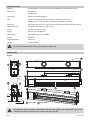
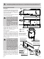
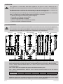
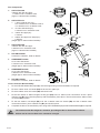
Operation & Installation Manual
RF1800
This appliance shall be installed in accordance with:
• Manufacturer’s Installation Instructions
• Current AS/NZS 5601 AS/NZS 3000
• Local Regulations and Municipal Building Codes including local OH&S requirements
This appliance must be installed, maintained and removed by an Authorised Person.
For continued safety of this appliance it must be installed and maintained in
accordance with the manufacturers instructions.
All Rinnai gas products
are A.G.A. certified.
Congratulations on the purchase of your RF1800 Decorative Gas Flame Effect appliance
We trust you will have many years of enjoyment from your purchase.
THIS MANUAL CONTAINS IMPORTANT INFORMATION. FOR SAFETY PLEASE READ
CAREFULLY BEFORE PROCEEDING WITH ASSEMBLY, INSTALLATION AND OPERATION
OF YOUR NEW FLAME FIRE AND GAIN A FULL UNDERSTANDING OF THE APPLIANCE.
Rinnai
i
RF1800 OIM
OPERATION TABLE OF CONTENTS
Before You Start
2
Safety3
Safety Devices
4
Appliance Features
5
Operation Instructions
5
Operational Safety
5
Power Failure
5
Cleaning6
When to call for Service
6
Service6
Installation Table of Contents
7
Contacts22
Rinnai
1
RF1800 OIM
BEFORE YOU START
INSTALLATION REQUIREMENTS
This appliance MUST BE installed by an authorised person.
The installation MUST conform to local regulations.
The installation MUST also comply with the instructions supplied by Rinnai.
Service and removal MUST BE carried out by an authorised person.
CERTIFICATION
The Rinnai RF1800 has been certified by the Australian Gas Association.
The Certification Number is shown on the appliance dataplate.
No parts or functions are to be modified or permanently removed from the heater.
Please keep these instructions in a safe place for future reference.
CARTON CONTENTS
The main RF1800 engine components are supplied in a crate, components for additional installation methods are
packed separately. The following table lists the contents for each component package, ensure that the components
listed for the installation method being installed are present before proceeding with the installation.
A
B
7
4
5
6
1
10
2
9
3
C
Item
Description
1
Rinnai RF1800 gas fire engine
2
Gas connection kit: 200mm 3/8 Flexi tube with plug and 3/8” - 1/2” reducing flare connector
3
Burner end cap
4
This Operation and Installation Manual
5
Rear reflector option for corner or fully recessed installation
6
Instructions for reflector panel installation
7
Rivet pack
8
End reflector option for through wall or fully recessed installation
9
Instructions for reflector panel installation
10
Rivet pack
Rinnai
8
2
Contents
A
B
C
●
●
●
●
●
●
●
●
●
●
RF1800 OIM
SAFETY
WARNING
DO NOT OPERATE THIS APPLIANCE WITHOUT READING AND UNDERSTANDING THESE
INSTRUCTIONS.
Taking time to familiarise yourself with the appliance’s features and operation will allow you to
get the most out of your appliance for years to come.
Please keep these instructions for future reference. Failure to comply with these instructions could
result in a fire or explosion, which could cause serious injury, death or property damage.
Improper installation, adjustments, service or maintenance can cause serious injury, death or property
damage. Such work must be performed by authorised personnel.
The appliance must be installed in accordance with the local gas and electrical authority regulations.
Flue terminal must always vent directly to outdoors.
DO NOT extend the flue vertically or horizontally in ways other than prescribed in the appliance
manufacturers’ installation instructions.
For information on gas consumption, see data plate on the appliance.
This appliance must not be installed where curtains or other combustible materials could come into
contact with it. In some cases curtains may need restraining.
When considering installation ensure minimum clearances as in the following drawing are adhered to
for both sides of the appliance:
0
50 in)
(m
500
(min
)
00
10in)
(M
0
30
Whe
n wi
thin
1
(Re 000
co
min mmend
ium
heig ed
ht)
300m
m of
1000
(min
)
floor
This appliance is not intended for use by persons (including children) with reduced physical, sensory
or mental capabilities or lack of experience and knowledge, unless they have been given supervision
or instruction concerning use of the appliance by a person responsible for their safety.
The appliance is not intended for use by young children or infirm persons without supervision.
Young children must be supervised when in the vicinity of this heater while it is in operation.
For protection of young children or the infirm a secondary guard is required.
If the supply cord is damaged or requires replacing, it must be replaced by the manufacturer or the
manufacturer’s agent or similarly qualified person in order to avoid a hazard.
DO NOT connect to an LPG Gas cylinder indoors.
A dedicated 240 V earthed 10 Amp power point must be used with this appliance.
DO NOT modify this appliance. Modifying from original specifications may create a dangerous situation
and will void your warranty.
ONLY THE FLUE COMPONENTS SPECIFIED BY RINNAI MUST BE USED.
Unpack the heater and check for damage. DO NOT INSTALL A DAMAGED HEATER. If the heater is
damaged, contact your supplier for advice.
Before installing the heater, check the label for the correct gas type (refer rating plate, inside the
appliance). Refer to local gas authority for confirmation of the gas type if you are in doubt.
Rinnai
3
RF1800 OIM
SAFETY
DO NOT sit or lean against the heater.
IMPORTANT
DO NOT post or allow children to post articles into the heater.
DO NOT cover or place articles on this heater.
DO NOT operate / install this heater in areas where painting is taking place, or in places such as
hairdressing salons, where there may be fluff and dust, and where aerosols are used.
DO NOT place articles on or against this appliance.
DO NOT use or store flammable materials near this appliance. Keep flammable materials away from
heater.
Combustible materials MUST NOT be placed where the heater could ignite them.
DO NOT spray aerosols in the vicinity of this appliance while it is in operation. Most aerosols contain
flammable substances which can be a hazard if used near this appliance when it is in use.
DO NOT use power boards or double adaptors to operate this appliance. The heater MUST NOT be
located below a power socket-outlet.
DO NOT place containers of liquid on top of the heater. Water spillage can cause extensive damage
to the appliance and create an electrocution hazard.
DO NOT CONNECT TO AN LPG GAS CYLINDER INDOORS.
Turn the heater ‘OFF’ when not in use.
DO NOT unplug the heater while it is in operation.
When the heater is operated for the first time or after long periods of non use a slight odour may be
emitted, this is normal. However if odours persist switch ‘OFF’ the appliance and contact Rinnai.
Appliances incorporating a live fuel effect and designed to operate with luminous flames, may exhibit
slight carbon deposits.
This is primarily a decorative appliance and has not been designed as a space heater.
NOT INTENDED FOR FIREPLACE INSERT
WHAT TO DO IF YOU SMELL GAS
DO NOT try to light any appliances.
DO NOT touch any electrical switches: do not use any phone in your building
Immediately close the shut-off valve at the gas meter or bottles
Call an authorised service technician
SAFETY DEVICES
Electrical Fuse:
The electrical circuits are protected by a fuse. When the fuse blows, the heater will not operate. The fuse must be
replaced by an authorised person.
Flame Failure Sensing System:
This device automatically cuts off the gas supply to the heater in the event of a flame failure.
Power Failure:
In the event of a power failure or power cut, the gas valves will automatically close. Refer to “Electrical Supply” on
page 10 for further details.
Rinnai
4
RF1800 OIM
APPLIANCE FEATURES
Heat Reflector Panels
(Additional Rear and End reflector panels not shown)
Outer Trim
Glass Burner
Glass Panels
OPERATION INSTRUCTIONS
To operate your appliance for the first time, ensure that the gas supply is on and that the appliance has been tested
and commissioned by the installer (refer to the “Commissioning Checklist” on page 20).
Your appliance should have been installed with a separate isolating wall switch mounted on a nearby wall and may
also have a start button connected to a relay*.
Turn the wall switch to the on position and within a few seconds you will hear a sparking sound and gas will start
to flow through the burner. Once a flame is established the spark ignition will stop.
If the appliance fails to ignite within about 5 seconds, the gas will stop flowing and the gas control will “lock out”.
This is most likely when the appliance has just been installed or has not been used for some time. Turn the wall
switch off and the on again and press the start button and the cycle will start again.
If the appliance fails to ignite after 4 attempts then consult the trouble shooting section on page 20 or contact
your installer or an authorised service person to arrange a service call.
OPERATIONAL SAFETY
This appliance is factory tested and the installation MUST BE tested by an authorised installer. You should not
experience any odour from your appliance other than initial burn off smell the first time it is used. Should any odour
persist after the initial burn in, turn off the gas supply and arrange for an authorised person to make a service call.
This appliance has a flame failure safety system which ensures that in the event of an ignition failure, gas supply
failure or flame being extinguished for any reason, the appliance will shut down. The appliance will attempt to restart automatically.
Lock Out
If the appliance fails to re-ignite then the appliance will “Lock Out” and will need to be re-set manually. This is done
by turning the power ‘OFF’ at the wall switch.
After manual reset wait at least 10 seconds before attempting to restart the appliance and if the appliance still fails
to ignite after 4 attempts then turn off the power and refer to the trouble shooting section on page 20.
NOTE
This appliance burns with a real flame and as such there are considerations to be made to ensure
the safety of children and the infirm. In such circumstances a fire guard should be secured in
front of the appliance.
Furniture and other objects must not be placed within 1 metre of the appliance.
POWER FAILURE
In the event of a power failure, your appliance cannot be operated until power is restored.
NOTE
Rinnai
If a power failure occurs while the appliance is in operation and if the wall switch is left in the ‘ON’
position, when the power is restored the appliance will then automatically restart.
* Provision of a latched relay (see page 21 for details) or other automated power supply cut off
can be used to prevent the appliance from restarting.
5
RF1800 OIM
CLEANING
Regular cleaning of your appliance is important to keep it looking its best. Some points on cleaning:
DO NOT attempt to clean appliance while in operation or when hot.
WARNING
DO NOT spray cleaners onto or around the burner as the liquid can get between the glass panels
and cause water spotting.
is important to keep the burner free from debris such as dust, insects and anything else that could cause a
•Itblockage.
Carefully use a vacuum cleaner to clean the gap between the two glass panels that make up the
burner.
burner and the glass panels can be cleaned using household glass cleaners, when doing so it is best apply
•The
cleaners by cloth rather than by spray. DO NOT spray cleaners onto or around the burner.
stainless steel reflectors and trims can be cleaned using standard household stainless steel cleaners. Take
•The
care not to scratch the steel or spray cleaners onto the burner
WHEN TO CALL FOR SERVICE
There are a few points to look out for that could indicate that your appliance requires a service call.
•If soot starts to form on any of the panels (trim or glass).
•If you can smell gas, regardless of whether the appliance is going or not.
NOTE
There can be a brief smell of gas as the appliance is going through the ignition sequence, however
this should soon stop once the appliance has started.
•If there is excessive noise or explosive ignition as the burner lights, this could be due to blocked burner ports.
the flames change shape or colour. Under normal operation the flames will be a bright, luminous, yellow
•Ifcolour.
If they become a dark, streaky, orange colour, or a very blue colour, this could indicate a problem.
Abnormal Flame Pattern
•If the flame looks abnormal. Signs of abnormal flame operation could be:
A very short flame that does not reach across to the burner.
A very long flame that reaches far beyond the flame burner or long yellow
flames.
A roaring noise when the appliance in operation or the flame “lifting off” from
the burner.
•If there are large soot deposits that keep building up on the burner or panels.
is excessive noise or explosive ignition as the burner lights, this could
•Ifbethere
due to blocked burner ports.
a smell of flue gas continues after the appliance has been operating for at
•Ifleast
10 minutes. This could indicate a blocked flue or other problem. This
smell is acceptable during the first few minutes as the flue heats up and starts
to draw.
the flames change shape or colour. When the appliance first starts the
•Ifflames
will tend to be quite blue for a few minutes but will change to a more
yellow/orange colour as the system heats up, this is normal, but if the flames
either stay very blue, or turn a dark, streaky orange colour, this could indicate
a problem. Contact Rinnai for advice.
SERVICE
In order for your appliance to give years of comfort and enjoyment, it is recommended that it is serviced on an
annual basis by a licensed service gas-fitter. Please refer to the back of this manual for contact details.
Disconnect the power and gas supply to the appliance before proceeding with the service.
Power Cord Replacement
If the power cord becomes damaged, replacement is to be by an authorised person only using a manufacturer
supplied part.
Rinnai
6
RF1800 OIM
INSTALLATION TABLE OF CONTENTS
Operation Table of Contents
1
Installation Safety
8
Specifications
9
Dimensions
9
Gas & Electrical Supplies 10
Clearances, Mantels, Surrounds, Recesses & Hearths
11
Ventilation12
Flue Requirements
12
Engine Installation
14
Appliance Gas Connection & Commissioning
18
Final Checks
20
Trouble Shooting
20
Commissioning Checklist
20
Wiring Diagrams
21
Contacts22
Rinnai
7
RF1800 OIM
INSTALLATION SAFETY
WARNING
This appliance must be installed by a suitably qualified person in accordance with local codes and AS/
NZS 5601
This is primarily a decorative appliance and has not been designed as a space heater
This appliance has been tested to AS 4558
DO NOT operate this appliance without reading and understanding these instructions first
This appliance is designed for installation into a timber framed construction and new or existing masonry
installations
NOT INTENDED FOR FIREPLACE INSERT
Only the approved flue components specified by Rinnai MUST BE used
This appliance must be installed into a well ventilated room in accordance with AS/NZS 5601
This appliance is designed for indoor installation only; NOT TO BE INSTALLED OUTDOORS
Rinnai is not responsible for incorrect or improper installations
All installations must be carried out by authorised personnel
Be sure to complete the installer details section of the user guide before signing off the installation
DO NOT place articles on or against this appliance
DO NOT store chemicals or flammable materials, or spray aerosols near this appliance
DO NOT operate with panels, covers or guards removed from this appliance.
DO NOT modify this appliance
Rinnai
8
RF1800 OIM
SPECIFICATIONS
Models:
RF1800L(N/P) “Left handed model”, RF1800R(N/P) “Right handed model”
Gas Types:
Natural Gas
Propane Gas
Description:
Indoor Decorative Appliance
Flue:
2x 150 mm stainless steel inner/ 200 mm galvanized steel outer
Minimum of 2.4 metres of flue, 3.6 metres if off-set bends are used
Flue Cowl: AGA approved 150 mm or 200 mm Flue Cowl(s) (dependant of flueing method)
Gas Connection:
3/8” BSPF Gas Flare onto gas control
Power: 230/240V AC 50hz, 1 Amp
Burner: Bunsen type atmospheric
Gas Control: SIT 840 with SIT 579. 402 DBC
Ignition:
Electronic
Flame Monitoring:
Flame rod
Control:
Isolating switch
For all other specifications refer to the appliance data plate
NOTE
DIMENSIONS
Engine
B
B
297
260
B
A
A
2174
1469
469
Power
Inlet
B
210
453
1825
A
180
B
30
48
A
78
35
40
NOTE
Rinnai
40
Gas Inlet
A
Open Side
B
Glass Side
The drawings above are for the Left handed version of this appliance. A right hand version is also
available, for which the dimensions are the same yet reversed.
9
RF1800 OIM
NOTE
The following installation instructions are for a left handed version of the appliance, when
installing the right handed version dimensions and other references will need to be reversed.
GAS & ELECTRICAL SUPPLIES
B
Gas Supply
A suitable gas supply needs to be provided
to the Left hand end of the appliance at the
lower front corner of the installation cavity.
The pipe sizing should be calculated to
supply at least 40 MJ/h
Allow sufficient pipe penetration to make the
connection as shown right.
NOTE
A
The gas inlet access point
for this appliance is provided
with a set of flaps to allow
consumer piping with fittings
attached to be passed through
for connection.
A
For vermin control ensure that
these flaps are closed again
once the piping has been
installed.
Electrical Supply
The appliance is supplied with a power
lead (approx. 1.8m long). This needs to be
connected to an isolating wall socket within
the cavity and connected to an isolating wall
switch, preferably located to the left of the
appliance, facing into the room, not inside
the framing cavity.
NOTE
If a power failure occurs while
the appliance is in operation
and if the wall switch is left
in the ‘ON’ position, when the
power is restored the appliance
will then automatically restart.
Provision of a latched relay (or
other automated power supply
cut off) can be used to prevent
the appliance from restarting,
refer to “Wiring Diagrams” on
page 21 for further details in
regards to latched relays.
This supply is used to isolate all power from
appliance. The power cord is designed for
a 230/240V AC 10 amp supply. Electrical
connections must be in accordance with AS/
NZS 3000 and installed by an authorised
person.
189 min.
A
Open Side
B
Glass Side
1982 max. over wall lining
B
A
This access hole is only
used when installing a
right handed applaince
Open the hole cover
plates to fit consumer
pipe and flexi tube
48
Use the supplied gas connection kit (200mm
3/8 Flexi tube with plug and 3/8” - 1/2”
reducing flare connector) to connect the
appliance to the consumer piping.
58 from
finished lining
Close the hole cover
plates over consumer
pipe and lock in place
Consumer pipe
1/2" flare nut
1/2" - 3/8" flare
reducer
3/8" flared flexi tube
200mm long
Rinnai10
Appliance
connection
point
RF1800 OIM
CLEARANCES, MANTELS, SURROUNDS, RECESSES & HEARTHS
Clearances
The appliance must be installed with the shown
minimum clearances to combustible materials.
0
50 in)
(m
500
(min
)
Mantles
00
10in)
(M
A timber mantel may be installed above this appliance
but must be within the grey area as shown here.
1
Timber Surrounds
(Re 000
co
min mmend
ium
heig ed
ht)
1000
(min
)
As with mantels when a timber surround is to be fitted,
ensure it complies with minimum timber clearances
of 300mm above and 150mm to each side.
Recesses
45°
If the appliance is to be installed into a recess the
recess must comply with the limitations shown right.
Mantel
MANTEL MUST NOT EXTEND BEYOND THIS AREA
X
NOTE
The same limitations apply to the sides
of the appliance.
X
It is the responsibility of the installer/
end-user to check the installation
instructions of these items and to
ensure the location is suitable.
This caution also extends to, but
is not limited to, ornaments such
as: Paintings, Prints, Photographs,
Tapestries, Mirrors, Stuffed Animals,
etc.
Rinnai does not take any responsibility
for any damage occurring to any items
installed above and in the vicinity of
the heater.
IDEA
* NOTE THAT SIDE CLEARANCES CAN BE
REDUCED FROM 300MM TO 50MM
300*
CAUTION
The installation of electrical appliances
above and in the vicinity of the heater
such as, but not limited to, Plasma
TV, LCD TV, Home Theatre Screens,
Speakers, etc. must comply with their
manufacturers’ instructions.
Wall
TV or Ornamentation Above The Heater
Top Trim
RECESS MUST NOT
EXTEND BEYOND
THIS AREA
45°
FIRE PROOF BOARD FOR
MINIMUM HEIGHT OF 300MM
100
FIRE PROOF
BOARD
Use either a shelf or mantel below the
TV or ornament or alternately you can
construct a recess to mount TV or
ornament on.
SIDE VIEW
Check the manufacturers installation
instructions for these items and ensure
the recess is suitable.
Hearths
Although a solid hearth is not required, if the appliance
is to be installed within 300mm of the floor, it is
recommended that protection is given to any flooring
surface directly in front of the unit as the appliance
produces a large amount of radiant heat and this
might cause damage to flooring and furnishings that
are too close.
Rinnai11
0
30
Whe
n wit
hin 3
00m
m of
floor
300
RF1800 OIM
VENTILATION
IMPORTANT
This appliance is a decorative flame effect appliance, the space or room in which the unit is
installed must have adequate fixed ventilation compliant with the requirements of AS/NZS 5601.
For Decorative Gas Log Fires this requires that one or more openings with a combined free
ventilation area of not less than 314 cm² shall be provided for each appliance.
The opening may be provided by any of the following options, provided that there is a ventilation
path to outside that is unobstructed by building material or insulation:
a) Directly through an outside wall (preferred option).
b) Through to an outside wall but offset.
c) Into a cavity ventilated to outside.
d) Into an underfloor space ventilated to outside.
e) Into a roof space ventilated to outside.
FLUE REQUIREMENTS
ONLY the Rinnai flue components described in this manual are to be used with this appliance.
IMPORTANT
The installation of the flue system MUST comply with the requirements of AS/NZS 5601.
Examples of the available flue component configurations are shown below.
D
D
Twin - Direct
(Option 1)
D
A
2.4m*
3.6m*
3.6m*
B
B1
B2
A
474mm
B3/4
FRONT
G
A
A
A
A
B
B3/4
B2
G
A
C
B
Twin - Extended Offset
A
C
C
Twin - Offset
G
C
C
2.4m*
C
Y Piece - Extended Offset
(Option 1)
3.6m*
Y Piece - Offset
3.6m*
Y Piece - Direct
VIEW
(Option 2)
(Option 2)
A
E
SIDE
VIEW
A
E
FRONT
F
E
E
F
SIDE
VIEW
F
E
C
C
F
A
A
E
A
E
E
VIEW
SIDE
VIEW
SIDE
VIEW
B
B
A
A
* This is the minimum flue height for the configurations as shown, for additional bends increase the flue height in accordance with AS/NZS 5601.
Y Piece - Direct: Allows the twin flues to be joined to a single flue for termination. It is recommended
that the flue be taken vertically as high as is practicable before joining to the Y Box assembly.
Y Piece - Offset / Extended Offset: Same as “Y Piece - Direct” with the inclusion of one 45° offset
or extended offset.
Twin - Direct: Uses two separate flue pipes to the flue termination point.
Twin - Offset / Extended Offset: Same as “Twin - Direct” with the inclusion of one 45° offset or
extended offset.
Minimum
Flue Heights
Y Piece Direct
2.4m
Y Piece Offset
3.6m*
Twin - Direct
2.4m
Twin - Offset
3.6m*
Twin - Extended Offset
3.6m*
* Only 1 x 45° bend set can be used on each flue for Offset or Extended Offset flue installations.
Additional bends may be utilised, however this will then require that additional vertical lengths
also be included to increase the flue height in accordance with AS/NZS 5601.
Rinnai12
RF1800 OIM
Flue Components
A.
AUFLUE150/200
1220mm twin skin flue pipe ø 150mm inner / ø 200mm outer
(approx 1180mm when installed)
B.
AUFLUEYILL18
1. Y piece collector box (1x) 2x ø 150mm inner / ø 200mm outer to
1x ø 200mm inner / ø 250mm outer.
2. 45° twin skin bends (2x) ø 150mm inner / ø 200mm outer.
3. 150mm flue pipe (2x) ø 150mm.
4. 200mm flue pipe over-wraps (2x) ø 200mm.
(height approx 615mm when installed)
D
G
C
F
C
C. AUFLUE200/250
1220mm twin skin flue pipe ø 250mm inner / ø 300mm outer
(approx 1180mm when installed)
B3
D. RFCOWL200/250
Connection ø 200mm, Outer ø 350mm
E.
F.
B4
B3
B2
AUBENDSET200/350
2x 45° twin skin bends ø 200mm inner / ø 250mm outer
(height approx 357mm when installed)
Y Piece Collector Box Assembly
B2
A
AUBENDSET150/200
2x 45° twin skin bends ø 150mm inner / ø 200mm outer
(height approx 322mm when installed)
G. RFCOWL150/200
Connection ø 150mm, Outer ø 300mm
B1
B4
A
A
E
1.
Fit the AUFLUE150/200 flue pipes (A) onto the engine using rivets and sealant as required.
2.
Fit the ø 150mm inner 45° bends (B2) but do not fix in place yet.
3.
Fit the ø 200mm outer 45° bends (B2) and leave loose.
4.
Fit the two 150mm ø 460mm lengths of flue pipe (B3) to the ø 150mm inner connections of the Y piece
collector box (B1), then fit and square up with the assembly from above. Then fix all but the ø 200mm outer
45° bends (B2) in place.
5.
Fit the two 200mm over-wraps (B4) over the ø 200mm outer 45° bends (B2) and the ø 200mm outer
connections of the Y piece collector box (B1) and fix all in place.
6.
Complete the flue to the termination point using AUFLUE200/250 (C) and RFCOWL200/250 (D) as required.
The minimum total flue height is 2.4 metres, providing the flue is direct without offsets.
IMPORTANT
Offsets can be used on flues over 3.6 metres in height.
Rinnai13
RF1800 OIM
ENGINE INSTALLATION
Installation Options
The appliance can be installed in 4
different ways. The basic appliance is
supplied ready for installation as a fully
open appliance where the appliance is
open to the front and the glass sides are to
the right and back. It is also available as a
right hand appliance if required.
IMPORTANT
All appliances are shown with
the open side foremost and
glass panels to the back and
right hand end. Even with the
insulation kits installed, the
glass panels remain in place.
Fully Open
Fully Enclosed
Corner Unit
Through Wall
Rear & End Reflector Kit Fitting
Reflector kits are used to convert the
appliance for the Corner, Fully Enclosed
and Through Wall installation options
and require fitting before the installation
continues. Unseen trims may need to
be cut away to make fitting of the wallboard easier and tidier, the trims to cut will
depend on the installation option.
IMPORTANT
Make sure that you have
clearly identified the panels
that are to be cut before
proceeding. It may be easier
to fit the insulation panel
prior to making any cuts.
Be sure to remove all the
protective plastic from any
panels that will be covered
by the insulation panels
Relieve corner of
unseen trim to allow wall
lining to fit behind the trim
Align faces
and edges
Drill and rivet
in place (4 places)
DO NOT
CUT THE SEEN
TRIM PANELS
Cut here for
Through Wall and
Fully Enclosed
Cut here for
Through Wall and
Corner Unit
Framing Drawings
The diagrams on the following pages show the framing requirements for each installation type.
IMPORTANT
The flue and engine must be installed before the wall can be lined. Remember that both gas and
electricity are required within the cavity (see, “Gas & Electrical Supplies” on page 10).
The framing must be self supporting and not place any load on the engine.
The flue system must also be supported and not placing load on the engine.
The framing shown is indicative only is not intended to illustrate the construction method. The
installation shows one flue option (using the optional Y-Piece) but does not represent a complete
system.
The appliance should be installed on a solid platform.
Gas and power supply must enter through the left hand end of the engine when viewed from the
open side (the reverse is true for a right handed appliance).
The wall lining above the appliance must be non combustible for a minimum off 300 mm above
the top trim.
When engine installation is complete, the fitting of cardboard from the packaging material to the
front flanges on both sides of the appliance with some low-tac masking tape will help to protect
the appliance from dust, paint, etc. of subsequent construction drawing into the appliance or
marking the glass.
Rinnai14
RF1800 OIM
Fully Open
There must be a clear
path for the flue to pass
Y piece flue is
shown, an
alternative is to
run two flues
through to
termination.
These sections must be fully
supported from above and
not place any load on the fire
Allow at least
20mm gap for
power and gas
250
715
Min
2183
Refer to
note on
top fixing
1000
Min
1000
Recommended
Minimum
463 Min
Min
468
o
cladd ver
ing
295
min over
cladding
Platform
recommended
Corner
Y piece flue is
shown, an
alternative is to
run two flues
through to
termination.
There must be a clear
path for the flue to pass
Allow at least
20mm gap for
power and gas
3
26
M
in
250
Min
1000
2183
Min
322 Min
over
cladding
468 Min
over
cladding
Platform
recommended
1000
recommended
minimum
463 Min
715
Refer to
note on
top fixing
Min
Rinnai15
RF1800 OIM
Fully Enclosed
Y piece flue is
shown, an
alternative is to
run two flues
through to
termination.
There must be a clear
path for the flue to pass
26
3
m
in
Allow at least
20mm gap for
power and gas
715
Min
Refer to
note on
top fixing
Min
2210
in
M
2
g
3 2 v e r d in
o la d
c
1000
Min
495
Min
1000
recommended
minimum
463
Min
250
Platform
recommended
Through Wall
Y piece flue is
shown, an
alternative is to
run two flues
through to
termination.
There must be a clear
path for the flue to pass
This section must be fully
supported from above and
not place any load on the fire
Allow at least
20mm gap for
power and gas
250
Min
715
Min
2210
Refer to
note on
top fixing
1000
Min
495
Min
295 Min
over
cladding
1000
recommended
minimum
Platform
recommended
Rinnai16
RF1800 OIM
TOP FIXING
In order to keep the top, unsupported end of the
engine in line with the framing above, a support
plate has been provided for fixing to the completed
framing.
21mm from cladding to
back of support plate
In some installations the support plate may not be
the most suitable solution. If this is the case then
use another seismic type strap to hold the engine
fast to the framing. Take care to make sure that the
wall cladding will line up with the inside edge of the
trim panel.
Shown here is the cut-out requirement for making
the support plate most effective.
115 Min
Support
Plate
WALL LINING
The wall lining above the top trim must be non-combustible for at least 300mm.
Wall Lining fits behind front edge of trim
Wall Lining
Trim
It is recommended that the plaster coat does not
cover the front trim.
IMPORTANT
Seismic Restraint: There are 4 holes in the base of the engine to hold the appliance in place.
Make sure that the engine is correctly aligned with where the wall lining will finish before fixing
the engine in place.
Rinnai17
RF1800 OIM
APPLIANCE GAS CONNECTION & COMMISSIONING
CAUTION
ISOLATE THE POWER AND GAS SUPPLIES BEFORE COMMENCING WORK ON THE APPLIANCE.
Once the engine has been installed and fixed to the building the gas and electricity can be connected, however
some installers elect to leave this until the decorating has been completed before finalising the installation.
CAUTION
If commissioning is to be carried out after the decorating is completed, then leave the protective
plastic coverings in place and cover the front of the engine with cardboard and low-tack tape to
prevent plaster dust and debris from entering and damaging the appliance.
Refer to the diagram below for part identification.
Reflector
Retainer
End
Reflector
Burner
Pressure
Test Point
Rear Reflector
Burner Fixing
Screws
Pressure
Adjustment
Burner Cover
Front Reflector
Spring Washer
and Nut
Power
Connection
Sparker and
Flame Rod
Assembly
Power
Plug
Earth Terminal
Gas Inlet
Inlet Pressure
Test Point
Preparation
Injector
Power Connection Detail
1.
To gain access to the burner, power, and gas connections, firstly rotate the Reflector Retainer upwards to
release the top of the End Reflector and remove this reflector.
2.
Remove the Burner Cover by carefully lifting straight up.
3.
Slide the Front Reflector towards the gas control so as to be able to gain purchase on both ends of the
reflector and remove it.
4.
Remove the 2 screws holding the burner in place and slide the burner assembly forward to gain access to
the Rear Reflector, slide the Rear Reflector towards the gas control so as to be able to gain purchase on both
ends of the reflector and remove it.
5.
Push the burner assembly as far back as possible without crushing the gas supply hose or wires etc.
Rinnai18
RF1800 OIM
Connecting Gas
1.
Use the supplied Gas Connection Kit to connect the consumer piping to the appliance gas inlet.
2.
Check for any crimps or kinks in the braided hose. Reconnect the gas supply and check for leaks.
3.
Remove all the protective plastic film from both sides of the appliance.
Gas Commissioning
240 VOLTS, RISK OF ELECTRICAL SHOCK!
WARNING
When performing the commissioning, the appliance electrical power will need to be connected.
Wiring inside this appliance may be at 240V potential, exercise CAUTION as there is potential for
electric shock from the exposed wiring and circuitry. DO NOT leave the appliance unattended
when power is connected and the panels are removed.
Installation and commissioning must be carried out by an authorised person.
DO NOT test for gas escapes with an open flame.
GAS PRESSURES
NOTE
Refer to the appliance data plate located inside the appliance on a swing tag for correct gas
pressure settings.
To check and set burner pressures:
1.
With the burner connected and pushed to the
back of the engine, using a suitable screw
driver loosen the captive Appliance Test Point
Pressure (ATPP) screw A and fit manometer
(an electronic manometer is recommended).
Refer images for ATPP location.
2.
Remove the brass plug B from the regulator
adjusting screw.
3.
Connect and turn ‘ON’ the mains supply to the
appliance. The spark ignition will start within a
few seconds and the burner will ignite. If the
burner fails to ignite within about 5 seconds, the
spark will stop and the gas will cease to flow.
It may take several attempts to get the burner
to ignite especially with a new gas installation.
Restart the appliance by turning the mains
power switch off, waiting a couple of seconds,
then switching back on.
4.
5.
Adjust the burner pressure with the regulator
adjusting screw C. Checking the pressures
against that of the data plate. Turning clockwise
increases the outlet pressure whilst turning
anticlockwise decreases the outlet pressure.
APPLIANCE OUTLET TEST POINT PRESSURE A
BRASS PLUG B
INLET
TEST POINT
GAS CONTROL
AND IGNITION
PACK ASSEMBLY
PRESSURE ADJUSTING SCREW C
Once adjusted turn the mains supply to the
appliance ‘OFF’, replace the brass plug B and
remove the manometer and re-tighten the ATPP
screw A. Check all connections and test points
for leaks using soapy water solutions.
WARNING
To ensure the correct operation of the valve it is necessary that the brass plug B is returned to
its original location.
6.
Turn the appliance ‘ON’ and ‘OFF’ a few times to confirm correct ignition and operation.
7.
Check the flame pattern, see “When to call for Service” on page 7.
8.
Replace all panels and reflectors previously removed, make sure that the burner is fastened in place and
that all protective plastic has been removed. After re-assembly confirm that the appliance is still operational.
Rinnai19
RF1800 OIM
FINAL CHECKS
Check that the appliance operates properly making sure that all the supplied parts are used and properly installed.
It is important that the customer is fully aware of how to operate the appliance properly and safely. Advise the
customer to fully read the operation sections of this manual to understand how to get the best out of their appliance.
Advise the customer of the need for regular servicing in order to maintain the warranty.
Complete the Commissioning Checklist.
TROUBLE SHOOTING
Symptom
Possible Cause(s)
Appliance does
not start
(no spark noise)
Mains power disconnected
Appliance is sparking
then stops (no flames)
Gas control locked out
→
→
Faulty spark electrode
Service call
Power fuse blown
Service call
Air in gas pipe
Service call
Gas supply turned off/empty
→
Faulty flame rod
Service call
Wind blowing on burner
→
Faulty flame rod
Service call
Wind blowing on burner
→
→
→
→
Flame starts but spark
keeps going
Flame starts but
then goes out
Appliance goes out
Owner Actions
Gas supply ‘Off’ or empty
Power supply turned off
Wind blowing on burner
Installer Actions
Check mains supply and isolating switch are ‘On’
Switch ‘Off’ and ‘On’ again *
Check HT lead
Check Electrode is not touching the bracket
Replace fuse
Purge gas pipes *
Turn on gas supply or change bottles *
Check flame rod lead
Check flame rod is not touching the bracket
Prevent excessive draft on burner
Check flame rod lead
Check flame rod is not touching the bracket
Prevent excessive draft on burner
Check gas supply or change/replace bottles
Check power is on
Prevent excessive draft ‘On’ burner
*
If the appliance fails to ignite after four (4) attempts, turn off the power and gas if possible and arrange for a service call or contact the installer if the unit is newly installed.
→
Owner corrective action is the same as that of an installer, all other corrective actions are for authorised persons only!
COMMISSIONING CHECKLIST
TO BE COMPLETED BY THE INSTALLER
Serial Number ___________________________________________________________
Installers Name___________________________________________________________
Installers License No.
___________________________________________________________
Installers Contact No.
___________________________________________________________
Certificate Of Compliance No.
___________________________________________________________
Installation Date __________/__________/__________
NO
1.
Is the appliance positioned in a suitable location with regards to clearances?
2.
Is the unit fixed in location?
3.
Have all gas connections been checked for leaks using a soapy water solution?
4.
Have you instructed the owner of the correct operation of this appliance before leaving?
5.
Have you left the operating instructions with the owner?
6.
Have you removed all PVC plastic coating material?
YES
Ensure all PVC plastic coating material is removed before operating the unit.
WARNING
If you have answered NO to any of the above questions you MUST NOT allow the appliance to be
operated until the item has been rectified.
Rinnai20
RF1800 OIM
WIRING DIAGRAMS
Appliance Wiring Diagram
Connector
Plug
3 Amp
MAINS IN
230/240 V a.c.
50 Hz
10 AMP MAX
BRN
BLU
1 - EMPTY
2 - EMPTY
3 - EMPTY
4 - EMPTY
5 - BLK
6 - BLK
7 - BLK
8 - EMPTY
9 - EMPTY
10 - BRN
11 - BLU
12 - GR
GR
GAS CONTROL 12 PIN PLUG
GR
GR
FLAME
OR
WH (HT LEAD)
SPARK
1 GAS CONTROL 12
(SIT840 with 0.579.402 DBC)
COLOUR
WH
BLU
BRN
GR
OR
WHITE
BLUE
BROWN
GREEN / YELLOW
ORANGE
Latched Relay Wiring Diagram
To Appliance
NO
COMMON
NC
10 Amp Relay
Mains
Supply
P
N
E
Rinnai21
RF1800 OIM
CONTACTS
Australia Pty. Ltd.
ABN 74 005 138 769
Head Office
10-11 Walker Street,
Braeside, Victoria 3195
P.O. Box 460
Tel: (03) 9271 6625
Fax: (03) 9271 6622
Internet: www.rinnai.com.au E-mail: [email protected]
National Help Line
Tel: 1300 555 545* Fax: 1300 555 655*
Spare Parts & Technical Info
Tel: 1300 366 388* Fax: 1300 300 141*
*Cost of a local call higher from mobile or public phones.
Rinnai has a Service and Spare Parts network with personnel who are fully trained
and equipped to give the best service on your Rinnai appliance. If your appliance
requires service, please call our National Help Line. Rinnai recommends that this
appliance be serviced every 2 years.
Rinnai22
13309 - RF1800 OIM Issue 1 11/12/13