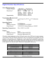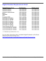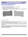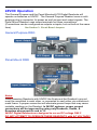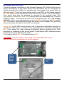
1
ProScale®
LCD Digital Readouts
Basic, General Purpose &
Panel Mounted LCD Digital Readouts
OPERATION
WARRANTY
Accurate Technology, Inc., warrants the ProScale® Digital Measuring Systems
against defective parts and workmanship for 1 year commencing from the date
of original purchase. Upon notification of a defect, Accurate Technology, Inc.,
shall have the option to repair or replace any defective part. Such services
shall be the customer's sole and exclusive remedy. Expenses incidental to
repair, maintenance, or replacement under warranty, including those for labor
and material, shall be borne by Accurate Technology, Inc. (Including freight or
transportation charges during the first 30 days).
Except as expressly provided in this warranty, Accurate Technology, Inc., does
not make any warranties with respect to the product, either expressed or
implied, including implied warranties of merchantability or fitness for a particular
purpose, except as expressly provided in this agreement.
Accurate Technology, Inc., shall not be liable for any special, incidental, or
consequential damages or for loss, damage or expense directly or indirectly
arising from the customer's use of or inability to use the equipment either
separately or in combination with other equipment, or for personal injury or loss
or destruction of other property, or from any other cause.
To request repair work (either warranty qualified parts or not), contact Accurate
Technology, Inc. directly by phone, fax, or e-mail. A Returned Merchandise
Authorization (RMA) number is required before returning a product for repair.
Accurate Technology, Inc.
+1 828.654.7920
800.233.0580
828.654.8824 (F)
www.proscale.com
[email protected]
SAFETY WARNING
Before installing this product on any
machinery disconnect all power and follow
the INSTALLATION manual supplied.
P/N 800-1402-001 Rev E, Copyright © 2010, Accurate Technology, Inc. All rights reserved.
Operation Manual for LCD Digital Readouts
Page 2 of 48
Table of Contents
SECTION 1
GENERAL INFORMATION .................................................................... 6
INTRODUCTION.........................................................................................................................6
ABOUT THIS MANUAL .................................................................................................................7
DIGITAL READOUT SPECIFICATIONS ...............................................................................................8
DIGITAL READOUT FEATURE MATRIX .............................................................................................9
DIGITAL READOUT REPLACEMENT CHART ......................................................................................10
SECTION 2
SET-UP ............................................................................................. 11
MOUNTING THE DIGITAL READOUT ..............................................................................................11
General Purpose & Basic DRO...........................................................................................11
Panel Mount DRO ............................................................................................................11
24VDC OPERATION .................................................................................................................12
General Purpose DRO ......................................................................................................12
Panel Mount DRO ............................................................................................................12
THE LCD ..............................................................................................................................13
SECTION 3
OPERATION ...................................................................................... 14
FUNDAMENTAL OPERATION ........................................................................................................14
KEY TIMING ...................................................................................................................14
KEY FUNCTIONS FOR STANDARD OPERATION ..................................................................................15
ON/OFF KEY ...................................................................................................................15
UNITS KEY .....................................................................................................................15
PLUS (+) & MINUS (–) KEYS ..............................................................................................16
DATUM KEY ...................................................................................................................16
BASIC FUNCTIONS ...................................................................................................................17
MEASUREMENT READING DIRECTION ....................................................................................17
KEY LOCK ......................................................................................................................17
DISPLAY RESOLUTION .......................................................................................................17
DISPLAYED MEASUREMENT UNITS ........................................................................................18
AUTO ON/OFF .................................................................................................................18
LINEAR SCALING .............................................................................................................18
SEGMENT OFFSET ADJUSTMENT ...........................................................................................19
UPPER/LOWER LIMITS .......................................................................................................19
ADVANCED FUNCTIONS .............................................................................................................20
ABSOLUTE VS INCREMENTAL MEASUREMENTS..........................................................................20
ABS .............................................................................................................................20
INC..............................................................................................................................20
SEND ...........................................................................................................................21
OFFSET ADDITION ...........................................................................................................21
PROGRAMMABLE OUTPUT OPERATION ...................................................................................22
PROGRAMMABLE OUTPUT POLARITY......................................................................................22
EXTERNAL KEYPAD INPUT ..................................................................................................23
SPECIAL FUNCTIONS .............................................................................................................23
SPECIAL FUNCTIONS .............................................................................................................24
SPECIAL FUNCTION 1: MONITOR, HOLD, DELETE .....................................................................24
SPECIAL FUNCTION 2: GO/NOGO ........................................................................................26
SPECIAL FUNCTION 3: ACCUMULATOR ..................................................................................27
SPECIAL FUNCTION 4: STATISTICS ......................................................................................29
COMPENSATION FUNCTIONS ......................................................................................................31
TEMPERATURE COMPENSATION ...........................................................................................31
NON-LINEAR COMPENSATION ..............................................................................................32
Manual Part # 800-1402-001 Rev E
Page 3 of 48
CHANGING THE BATTERY...........................................................................................................35
CIRCUIT BOARD JUMPERS .........................................................................................................36
General Purpose & Basic DRO Circuit Board.......................................................................37
Panel Mount DRO Circuit Board ........................................................................................37
SECTION 4
Pr
Pr
Pr
Pr
Pr
Pr
Pr
Pr
Pr
Pr
Pr
Pr
Pr
Pr
Pr
Pr
Pr
Pr
Pr
Pr
Pr
Pr
Pr
Pr
Pr
Pr
Pr
Pr
Pr
Pr
Pr
Pr
Pr
PROGRAMMING ................................................................................. 38
1 – Datum Key ........................................................................................................39
2 – Direction ...........................................................................................................39
3 – Key Lockout ......................................................................................................39
4 – Display Resolution .............................................................................................39
5 – Movement Required for DRO Auto-On function ....................................................39
11 – Displayed Measurement Units ...........................................................................40
12 – Auto-Off Time..................................................................................................40
13 – Linear Compensation........................................................................................40
14 – ProScale Compatibility ......................................................................................40
21 – Backlight Control..............................................................................................41
22 – ABS/INC Key Operation ....................................................................................41
23 – Auxiliary Keypad Enable ...................................................................................41
24 – Special Functions. ............................................................................................41
25 – Special Functions Option. .................................................................................41
26 – Position Monitor Drift Tolerance. .......................................................................42
27 – Use Soft Limits. ...............................................................................................42
28 – Lower Soft Limit Position. .................................................................................42
29 – Upper Soft Limit Position. .................................................................................42
30 – Offset Addition Enable......................................................................................42
31 – Offset Addition Preset 1....................................................................................42
32 – Offset Addition Preset 2....................................................................................42
33 – Offset Addition Preset 3....................................................................................43
34 – Offset Addition Preset 4....................................................................................43
35 – External Keypad Input 1...................................................................................43
36 – External Keypad Input 2...................................................................................43
37 – Programmable Output Polarity ..........................................................................44
38 – Programmable Output Operation. .....................................................................44
39 – Non-Linear Compensation Enable......................................................................45
40 – Non-Linear Compensation Interval. ...................................................................45
41 – Temperature Compensation Enable...................................................................45
42 – Temp. Comp. Low Position. ..............................................................................45
43 – Temp. Comp. High Position. .............................................................................45
44 – Temperature Compensation Coefficient. ............................................................45
SECTION 5
MISCELLANEOUS............................................................................ 46
FREQUENTLY ASKED QUESTIONS .................................................................................................46
SECTION 6
ACCESSORIES................................................................................. 47
ProRF SPC .......................................................................................................................47
ProRF Encoder.................................................................................................................47
ProMUX...........................................................................................................................47
Analog Interface Unit .......................................................................................................47
SPC Converter .................................................................................................................47
Operation Manual for LCD Digital Readouts
Page 4 of 48
FCC NOTICE
This equipment has been tested and found to comply with the limits for a class
B digital device, pursuant to part 15 of the FCC Rules. These limits are
designed to provide reasonable protection against harmful interference in a
residential installation. This equipment generates, uses and can radiate radio
frequency energy and if not installed and used in accordance with the
instructions, may cause harmful interference to radio communications.
However, there is no guarantee that interference will not occur in a particular
installation. If this equipment does cause harmful interference to radio or
television reception, which can be determined by turning the equipment off and
on, the user is encouraged to correct the interference by one or more of the
following measures:
•
Increase the separation between the equipment and the receiver.
•
Connect the equipment to an outlet on a circuit different from that to
which the receiver is connected.
•
Consult the dealer or an experienced radio/television technician for
help.
Operation with non-approved equipment is likely to result in interference to
radio and TV reception. The user is cautioned that changes and modifications
made to the equipment without the approval of the manufacturer could void the
user’s authority to operate this equipment.
Manual Part # 800-1402-001 Rev E
Page 5 of 48
SECTION 1
GENERAL INFORMATION
Introduction
ProScale® digital measuring systems are affordable precision electronic
devices for making linear measurements with speed and accuracy. ProScale
consists of a SCALE, an ENCODER (also called READHEAD) and a DIGITAL READOUT
(DRO). ProScale Models 150 and 250 use Capacitive Absolute measuring
technology, while the Model 180, 280, 380 & 580 systems use Inductive
Incremental measuring technology.
ProScale is ideal for most measuring requirements up to 6m (20ft.) where high
accuracy, better than 10 µm, (approximately .0005”) is not needed, but
affordable repeatability, (better than a tape measure), or accuracy to 50 µm
(.002”) is desired.
Because ProScale shows the exact measurement on its Digital Readout, it
eliminates the guesswork involved in reading and interpreting tape measures,
scales & pointers, or shaft encoders. It is compatible for any general purpose
measurement application where data is collected (SPC, RS232, RS485 or
wirelessly) and/or digital accuracy and repeatability is desired. It is also
suitable for retrofitting, or as original equipment, on most types of machinery.
ProScale Model 150 & 250 General Purpose Measuring Systems and products
based on Absolute measuring technology can be used with any of the several
different Digital Readout models available.
ProScale Model 180, 280, 380 & 580 Systems and the products using Inductive
technology may be used with a select group of Digital Readouts available from
Accurate Technology.
This manual covers only Digital Readouts (DROs) with an LCD display and with
operating firmware (FW) of 3.0 or greater.
Operation Manual for LCD Digital Readouts
Page 6 of 48
About This Manual
This manual includes Operating and Programming
information for:
ProScale Basic, General Purpose and Panel Mount
LCD Digital Readouts with firmware 3.000 or higher.
(Firmware version is displayed on power-up, ie P3.000)
P3.000
LCD BASIC Digital Readout
Part Number 700-1600-230
LCD General Purpose Digital Readout
Part Number 700-1600-235 (Battery Operation)
Part Number 700-1600-235G (24VDC Operation)
Part Number 700-1600-236* (with compensation)
LCD Panel Mount Digital Readout
Part Number 700-1600-435 (Battery Operation)
Part Number 700-1600-435G (24VDC Operation)
(Not compatible with older M100 & M200 Systems)
These Digital Readouts are compatible with ProScale Models 150, 250, 180,
280, 380 and 580 ProScale measurement systems as well as several other
ProScale products using integrated measuring systems.
The BASIC and General Purpose Digital Readouts are also backward
compatible with legacy ProScale Models 100 & 200 and other products using
these models as the integrated measuring device.
* Supplied with Model 580, ProKit 580, ProPanel and ProTable products
This manual DOES NOT include installation information for
any other ProScale product.
Manual Part # 800-1402-001 Rev E
Page 7 of 48
Digital Readout Specifications
Linear Measurements:
Display Ranges:
Resolution:*
Repeatability:
+ 999.999 in; + 399 63/64 in
+ 9999.99 mm; + 999.999 cm
.1inch
.1mm
.1cm or
.01inch .01mm .01cm or
.001inch .01mm .001cm or
.0005inch .01mm .001cm
.001in or .01mm or .001cm
Temperature Measurement:
Accuracy:
+ 1º C from 0 to 70º C, + 2º C otherwise.
Resolution:
.1º C
Operating Power:
Basic:
General Purpose:
Panel Mount:
2 AA Batteries
2 AA Batteries or 9-24VDC
1 CR123 3V Lithium Battery or 24VDC
Operating Temperature:
32 to 120°F, 0 to 50°C
Output:
Basic:
General Purpose:
Panel Mount:
None
Mitutoyo Digimatic® SPC
Mitutoyo Digimatic® SPC
* Position data displayed on the LCD and sent to the SPC port is auto-ranging.
This means that the defined resolution may be temporarily overridden by the
system if the position to be displayed or sent exceeds the allowable maximum
position for that resolution. In that case, the system will continue to reduce the
resolution until either an allowable resolution is achieved or to 1 decimal place
to the right of the decimal point. Maximum displayable values are:
Inch Resolution
Maximum Value (Inches)
4 decimal places
3 decimal places
2 decimal places
1 decimal place
99.9999
999.999
9999.99
99999.9
Millimeter Resolution
Maximum Value (mm)
2 decimal places
1 decimal place
9999.99
99999.9
Table 1.1
Maximum Resolution
Operation Manual for LCD Digital Readouts
Page 8 of 48
Digital Readout Feature Matrix
This matrix is shown for comparison of features available among the several Digital Readouts
available from Accurate Technology. Readouts and their features that are Grayed Out are not
supported in this manual.
Surface Mount
Basic GP
DRO Function:
Battery Operation
•
24VDC Operation
Programmable Datum
•
Selectable Resolution
•
Selectable Units
•
Fractions
•
Auto on/off
•
Offset Addition
Upper/Lower Limit
•
Go/NoGo
Monitor Position
Drift Alert
Backlight
Noise Suppression
•
Linear Compensation
•
Non-Linear Compensation*
Temperature Compensation*
Sum/Difference
Statistics
Use w/Model 150/250
•
Use w/Model 180/280/380/580•
Use w/ProRF Wireless SPC
Output Signal(s)
None
•
•
•
•
•
•
•
•
•
•
•
•
•
•
•
•
Compact
LCD
•
•
•
•
•
•
Panel Mounts
LCD LED Dual
•
•
•
•
•
•
•
•
•
•
•
•
•
•
•
•
•
•
•
•
•
•
•
•
•
•
•
•
•
•
•
•
SPC
•
•
•
•
•
•
None
SPC
RS485
RS232
SPC
•
* Available ONLY on Part # 700-1600-236 supplied with select
ProScale systems. These General Purpose DROs will indicate
Firmware ending in “C”. (Firmware version is displayed on power-up,
ie P3.000C).
Manual Part # 800-1402-001 Rev E
Page 9 of 48
Digital Readout Replacement Chart
Digital Readout Type
General Purpose
General Purpose
General Purpose
General Purpose Basic
Basic
Standard
SPC
Programmable
Panel Mount, Battery
Panel Mount, Battery
Panel Mount, 24VDC
Panel Mount, Battery
Panel Mount, Battery
Panel Mount, 24VDC
Panel Mount, Battery
Panel Mount, 24VDC
Incremental Model 100/200
Incremental Model 100/200
Incremental Model 100/200
Old Number
700-1600-225
700-1600-200
700-1600-001
700-1600-220
701-1495-001
701-1500-00x
701-1505-00x
701-1115-00x
700-1600-450
700-1600-405
700-1600-305
700-1600-400
701-1570-001
701-1560-001
701-1525-00x
701-1550-00x
701-2000-025
701-2000-002
701-1495-002
Replacement
700-1600-235
700-1600-235
700-1600-235
700-1600-230
700-1600-230
700-1600-235
700-1600-235
700-1600-235
700-1600-435
700-1600-435
700-1600-435
700-1600-435
700-1600-435
700-1600-435
700-1600-435
700-1600-435
700-1600-230
700-1600-230
700-1600-230
( ‘x’ denotes any number from 1-4.)
For the latest information about available Digital Readouts for ProScale
Measuring Systems please visit:
http://www.proscale.com/Digital Readouts/Digital Readouts.htm
Operation Manual for LCD Digital Readouts
Page 10 of 48
SECTION 2
SET-UP
Mounting the Digital Readout
General Purpose & Basic DRO
The SURFACE MOUNT Digital Readout may be mounted:
• Using Velcro or Double sided tape
• Drilling out the 3 holes from the inside of the case
• Using any of the six holes on the back of the case which may tapped for M2
or 4-40 screws.
Panel Mount DRO
A cutout should be made in the panel at least 90mm x 90mm (3.6 x 3.6 inches),
but no larger than 93mm x 93mm (3.7 x 3.7 inches).
The cases of the Digital Readout are designed to "sandwich" panel thicknesses
between 3mm (0.125") and 20mm (0.750") between the front and rear Digital
Readout cover.
NOTE: If Panel is thinner than 3mm (0.125 in), shorter screws must be
used for the Digital Readout casing or damage to the front cover of the
Digital Readout will occur.
Manual Part # 800-1402-001 Rev E
Page 11 of 48
24VDC Operation
The General Purpose and the Panel Mounted LCD Digital Readouts will
operate on batteries or 24VDC. The General Purpose Readout uses a multipurpose plug-in connector for power as well as input and output signals. The
Panel Mount Readout uses screw terminals for these connections.
(Connections can be configured as outputs or inputs, but not both at the same
time).
See Section 3: Circuit Board Jumpers
General Purpose DRO
Common
Input / Output Pin
24VDC
SPC Output
Encoder Input
Panel Mount DRO
SPC Output
24VDC Input
Common
Encoder Input
Input / Output Pin
Notes:
When powering Readouts with 24VDC the Scale and the Readout’s ground
must be connected to each other, or connected to each other via a machine’s
metal frame. A proper connection will eliminate ground loops that may cause
unstable readings on the Readout. In 24VDC systems, proper ground
connections will be improved by using only Readouts, Scales, &
Encoders whose part #’s end in ‘G’.
24VDC Digital Readouts are designed to run on DC voltage ONLY.
DO NOT ATTEMPT TO OPERATE THESE READOUTS with AC VOLTAGE!
Operation Manual for LCD Digital Readouts
Page 12 of 48
The LCD
The above figure illustrates all the segments available on the LCD
Pressing and holding the ON/OFF and UNITS key for 10 seconds with
power OFF will perform a full segment LCD test, display the current
firmware version, AND RESET ALL PROGRAMMING PARAMETERS TO
FACTORY DEFAULT VALUES.
NOTE: The DRO may also be defaulted to original factory settings by removing
the battery and then pressing and holding the UNITS key while re-inserting
battery. *
* Internal jumper JP3 must be set to the Program Enable position to allow
the DRO to be reset to factory defaults as described above.
Manual Part # 800-1402-001 Rev E
Page 13 of 48
SECTION 3
OPERATION
Fundamental Operation
The following operations & functions apply to the Basic, General Purpose and
Panel mount LCD Digital Readouts.
KEY TIMING
The keys pictured below have multiple functions. Timing (how long a key is
depressed) is important. This manual uses the term “momentarily” to describe
a key press and release of less than .8 seconds. Whereas “press and hold” is
used to describe a key press and release of 1 second or longer.
See Table Below:
Momentarily
Press & Hold
How long a key is pressed?
Less than .8 seconds
More than 1 second
When is key function executed?
On key release
While holding
A function is executed on the “key release” for momentary key presses.
A function is executed after the allotted time has elapsed for “press & hold”
operations. See Table Below:
Momentarily Press
Cycles measurement units:
inches, fractions, mm
Press & Hold
(in programming mode)
Increments program parameter list
Displays Pr #
Plus (+)
(in programming mode)
increments displayed value
increments parameter value
increments faster
increments faster
(in programming mode)
forces reading to programmed
datum value
forces parameter to factory default
After 6 seconds: battery voltage
After 9 seconds: Temperature
no effect
Minus (-)
(in programming mode)
decrements displayed value
decrements parameter value
decrements faster
decrements faster
UNITS
Datum
Operation Manual for LCD Digital Readouts
No effect
Page 14 of 48
Key Functions for standard operation
ON/OFF KEY
Momentarily press
Momentarily press the ON/ OFF key to turn DRO off then momentarily press it
again to turn it back on. The Firmware version is displayed for two seconds at
power-on.
UNITS KEY
Momentarily press
Momentarily depressing the UNITS key will display measurement/position
information in inches, fractions or millimeters (or centimeters). With each key
press, the DRO will cycle through decimal inches, fractions (16ths, 32nds,
64ths) and millimeters (or centimeters). To limit the modes that may be
displayed by depressing the UNITS key See Programming Parameter (Pr11).
When the DRO is in 1/16 or 1/32 inch fraction mode, a series of “bars” in the
upper right corner of the LCD, each representing 1/64th of an inch, may
appear. (ie. When in 1/16 inch mode and three bars are showing, the
measurement displayed is rounded down to the closest 1/16 inch and each
illuminated bar indicates an additional 1/64 of an inch of additional
measurement.) For better resolution, switch to 1/32 or 1/64 mode. For the best
resolution switch to a decimal mode.
When the measurement is greater than 99 63/64 inches, a +100 and/or +200
will illuminate in the upper right portion of the display to indicate this amount
must be added to the displayed reading. ie: If the measurement is 154 5/8
inches, 54 5/8 and +100 will be illuminated on the display. If the measurement
is -307 23/64 inches, - 7 23/64, +100 and +200 will be illuminated on the
display.
Manual Part # 800-1402-001 Rev E
Page 15 of 48
PLUS
(+) & MINUS (–) KEYS
Momentarily or Press & Hold
Momentarily depressing the + or – key increments or decrements the current
displayed value by one unit of measurement.
Pressing and holding the + or – key will cause the displayed value to change
continuously. Continue pressing the key to cause the amount of change to
speed up. This allows for quick adjustments over a large range of values.
These keys may be locked out to prevent accidental offset entries.
See LOCK FUNCTION and Programming Parameter (Pr3).
DATUM KEY
Momentarily press
Press & Hold
The DATUM key is used to change the currently displayed value.
Momentarily pressing the DATUM key forces the display to a user programmed
value. This can be zero or any other displayable value.
See Programming Parameter (Pr1).
The DATUM key can be locked out to prevent accidental entries.
See LOCK FUNCTION and Programming Parameter (Pr3).
Press and hold the DATUM key for 6 seconds to display the battery voltage.
Press and hold the DATUM key for 9 seconds to display the temperature.
The temperature is displayed in the format “xx.x F” or “xx.x C” where xx.x is the
temperature and the units are in degrees Fahrenheit or degrees Celsius based
on the current measuring units setting (Inch or Metric). The temperature
readout will continue to be displayed until the datum key is released.
Temperature is sampled on startup and every 10 minutes thereafter.
Operation Manual for LCD Digital Readouts
Page 16 of 48
Basic Functions
MEASUREMENT READING DIRECTION
Once the system has been put into operation, if the direction of readings,
(positive or negative values) is opposite the desired direction, the DRO
programming may be changed to correct the direction.
See Programming Parameter (Pr2).
KEY LOCK
The Digital Readout provides a function that can be used to “lock-out” the
position offset adjustment keys (+, DATUM , –) to prevent accidental changes of
the current displayed value. To activate the Lock function, press and hold the
ON/OFF key and then momentarily press the UNITS key. The word LOCK will be
displayed in the upper left corner of the LCD. When
the LOCK symbol is displayed, the +, DATUM and –
keys become inactive.
To de-activate the Lock function, press and hold the
ON/OFF key and then momentarily press the UNITS key.
The Lock function can also be enabled through programming. This allows a
more permanent Lock function since programming can be disabled with a
hardware jumper inside the DRO. See Programming Parameter (Pr3)
DISPLAY RESOLUTION
Four display resolutions are available with all the LCD DRO’s.
.1in
.1mm .1cm
or
.01in .01mm .01cm
or
.001in .01mm .001cm
or
.0005in .01mm .001cm
To change to another display resolution See Programming Parameter (Pr4)
NOTE: Data displayed on the LCD and sent to the SPC port is auto-ranging.
This means that the selected resolution may be temporarily overridden by the
DRO if the position to be displayed exceeds the maximum displayable position
for the selected resolution. The DRO will continue to reduce the resolution until
either an allowable resolution is achieved or to 1 decimal place to the right of
the decimal point. Allowable ranges are:
Inch Resolution
4 decimal places
3 decimal places
2 decimal places
1 decimal place
Maximum Value (Inches)
Millimeter Resolution
2 decimal places
1 decimal place
Maximum Value (mm)
Manual Part # 800-1402-001 Rev E
99.9999
999.999
9999.99
99999.9
9999.99
99999.9
Page 17 of 48
DISPLAYED MEASUREMENT UNITS
The measurement units displayed on the Readout when the UNITS key is
depressed is user configurable. The table below provides a matrix for selecting
which units will be displayed (based on the value entered in programming
parameter Pr11).
See Programming Parameter (Pr11).
Programming Parameter Pr 11 Value
0
1
2
3
4
5
6
Measurement Units Displayed
All inch units, metric in millimeters
Millimeters only
Decimal inches and millimeters
Decimal inches and centimeters
All inch units, metric in centimeters
Centimeters only
Decimal inches only
AUTO ON/OFF
In order to prolong battery life, the Digital Readout has a built-in function that
will turn off the LCD after a period of no encoder movement or key activity. This
function does NOT turn off power to the encoder so the system will not lose its
position. Auto shutoff is programmable from 0 (always on), to 240 minutes
before going into sleep mode. Press the ON/OFF key or move the scale to wake
up the DRO. Any key press or encoder motion while the DRO is not in sleep
mode will restart the auto shutoff timer.
The default time period before the LCD turns off is 15 minutes. This time
period may be changed, or completely disabled through programming.
See Programming Parameter (Pr12).
LINEAR SCALING
All LCD Digital Readouts have the ability to “scale” the actual measurement.
This function is useful when the actual measurement must be multiplied or
divided before being displayed. Care should be taken when using this function
since invoking it will cause the unit to display a reading different than the actual
measured value.
This function has a range of: 0.0001 to 99.9999 allowing the actual measured
value to be multiplied or divided in very small or very large increments.
See Programming Parameter (Pr13).
Operation Manual for LCD Digital Readouts
Page 18 of 48
SEGMENT OFFSET ADJUSTMENT
This function applies to ProScale Model 150 & Model 250 systems and all other
ProScale products employing Absolute measurement technology that measure
more than 17 inches (430mm).
If the scale on your product looks like this:
It uses Absolute measuring technology
For Scales that are longer than 17 inches (430mm), multiple Scale pattern
segments are installed end-to-end on the aluminum extrusion. This provides a
quasi-absolute measurement capability in which the Encoder can calculate its
position on any individual segment but cannot determine which particular
segment it is on. To solve this problem, the Digital Readout tracks which
segment the Encoder is on by detecting the transition between one segment
and adjacent segments. In certain situations, the crossing from one segment to
another may not be detected. This may occur if the Encoder is disconnected
from the Digital Readout and then moved along the Scale to another segment.
It may also occur if the Encoder is moved too quickly between segments. If the
segment tracking count is incorrect because of one of the above situations, the
user can re-adjust the Readout to correct the error. This adjustment is referred
to as the SEGMENT OFFSET ADJUSTMENT.
To add one segment value
(430.08mm) to the displayed value, press and hold the UNITS key and then
momentarily press the + key. The displayed position will increase by
430.08mm (16.933 inches). To subtract one segment, 430.08mm, from the
displayed value, press and hold the UNITS key and then momentarily press the key. This function is operative only when Pr14 is set to 1.
See Programming Parameter (Pr14).
UPPER/LOWER LIMITS
The Digital Readout can display either LL for Lower Limit or UL for Upper Limit
if a pre-programmed upper or lower reading is exceeded. Upper and Lower
Limits are set with Programming Parameters Pr28 and Pr29 but are only active if
Pr27 is set to 1. The LCD display toggles for 2 seconds between current
position and LL if the Lower Limit is exceeded, or UL if the Upper Limit is
exceeded. This continues as long as either limit is exceeded.
See Programming Parameters (Pr27, 28, 29).
In addition, the programmable output can be configured to activate on General
Purpose Digital Readouts when either the Upper or Lower limit is exceeded.
See PROGRAMMABLE OUTPUT OPERATION.
Manual Part # 800-1402-001 Rev E
Page 19 of 48
Advanced Functions
The following additional functions & operations are
available on General Purpose Digital Readouts
See PROGRAMMING PARAMETER (Pr23).
ABSOLUTE VS INCREMENTAL MEASUREMENTS.
The Digital Readout has two measurement “indexes”. One
is referred to as ABS and the other is INC. The ABS
measurement setting is designed to allow the user to set
an “absolute“ zero point on the Digital Readout referenced
from a fixed or known position. The INC measurement
setting is designed to take relative or “incremental” distance measurements
from one arbitrary point to another. The settings operate independently
allowing separate position offsets to be programmed for ABS and INC. The
Absolute position of the measuring system is not lost when using the
Incremental (INC) settings and will be recalled and displayed when the Readout
is returned to Absolute (ABS) mode. The terms “Absolute” and
“Incremental” are used here to describe a measurement function or
technique and should not be confused with the terms Absolute and
Incremental when used in reference to the type of “Measuring
Technology” employed by different ProScale products.
ABS
The Digital Readout automatically enters ABS (Absolute) mode when power is
first applied. This is indicated by the ABS symbol in the upper left corner of the
LCD. While in the ABS mode, all position measurements are related to the
current system reference point. To enter the INC
(Incremental) mode, press & hold the ABS/INC
key for 1.2 seconds.
NOTE: To change the timing of this key to a
momentary press to enter INC mode, See
Programming Parameter (Pr22).
INC
While in the INC (Incremental mode), the INC symbol is shown in the upper left
corner of the LCD. When the INC mode is initially entered, the displayed
position will change to reflect a new reference point at the current position of
the Encoder. This is typically a position of zero (0) but may be changed by
using the + or – Key to enter an offset. Moving the Encoder in either direction
will display the distance moved from the initial Incremental starting point (plus
any offset). To complete another incremental measurement from the new
position, momentarily press the ABS/INC key. The Digital Readout will again
change to 0.00 (or the previously programmed offset). To return to the ABS
mode, press and hold the ABS/INC key for 3 seconds.
Operation Manual for LCD Digital Readouts
Page 20 of 48
SEND
The Digital Readout has an output port that can be used to send measurement
information to a compatible SPC device such as a data acquisition unit or
wireless transmitter (See Section 6: Accessories). After connecting the SPC
device to the 10 pin connector on the Digital Readout, the user may initiate the
data transmission by momentarily pressing the SEND key. This instructs the
SPC device to acquire the data from the Digital Readout. Pressing the SEND
key will cause Snd to display on the LCD for 1 second to show activation of the
send function (even if no SPC device is attached to the Digital Readout).
All inch modes are transmitted as decimal inches. All metric modes are
transmitted as millimeters. The SPC position data transmitted is typically the
displayed position on the LCD with the exception of when Special Function
Mode is set to Measurement Accumulation or Statistics modes (See Special
Functions). In those modes, the displayed (calculated) values are sent, NOT
the current encoder position.
The data format and connector style of the DRO SPC output is Mitutoyo
Digimatic®. This is an industry standard that can be interfaced with most
available SPC products including multiplexers & RS232 converters (See
Section 6: Accessories). If no SPC device is attached to the Digital Readout,
the SEND key has no other function.
OFFSET ADDITION
Offset addition allows values to be pre-programmed that are then added to the
measurement and the sum is displayed on the LCD. This function allows the
user to quickly switch from one reference point to another.
The General Purpose DRO can support up to 4 user definable offsets that can
be added to the current ABS position. PROGRAMMING PARAMETER PR30 enables or
disables this function. For example: If PR30 = 2, only offset 1 and 2 are available
for use. PARAMETERS PR31 through PR 34 are the individual offset adders
respectively.
When enabled, the operator scrolls through the active offsets by pressing the
F1 key. The numbers 1, 2, 3, 4 will be displayed in the upper left corner of
the LCD with each press of F1. When no numbers are displayed, no offset
addition is active.
When the number 1 is displayed in the upper left corner, Offset Addition Preset
1 (PR31) has been applied to the measurement and the result is now displayed
on the LCD.
When the number 2 is displayed in the upper left corner, Offset Addition Preset
2 (PR32) has been applied to the measurement and the result is now displayed
on the LCD.
Manual Part # 800-1402-001 Rev E
Page 21 of 48
When the number 3 is displayed in the upper left corner, Offset Addition Preset
3 (PR33) has been applied to the measurement and the result is now displayed
on the LCD.
When the number 4 is displayed in the upper left corner, Offset Addition Preset
4 (PR34) has been applied to the measurement and the result is now displayed
on the LCD.
PROGRAMMABLE OUTPUT OPERATION
The multi-purpose connector on the General Purpose Readout provides a
power input connection and, a keyboard input or solid-state output (.1A / 30
VDC) connection. The input and output functions are mutually exclusive and
cannot be used at the same time.
The output signal can be configured to activate on the following conditions:
• Special Function 1: Monitor drift condition
• Special Function 2: Go/NoGo function
• Upper/Lower LIMIT error
The LCD will flash when any of the conditions above are encountered, but the
output signal only changes state once and then toggles back when an intolerance condition is restored. The output can be configured for normally open
(N/O, not conducting to ground) or normally closed (N/C, conducting to ground),
see PROGRAMMABLE OUTPUT POLARITY.
See PROGRAMMING PARAMETER (Pr38) & Circuit Board Jumper JP5
Caution: The output remains active during Programming. If parameters relating
to the output are changed during Programming the output signal could become
active! When the Monitor mode is active AND the programmable output is
enabled, the hardware output will not become active until the error condition
has lasted at least 2 consecutive seconds.
PROGRAMMABLE OUTPUT POLARITY
The polarity of the programmable output signal when not activated is user
defined. The output is a transistor that conducts to Negative. The factory default
is normally open (NO).
See PROGRAMMING PARAMETER (Pr37).
Common
Input / Output Pin
Operation Manual for LCD Digital Readouts
24VDC Input
Page 22 of 48
EXTERNAL KEYPAD INPUT
The multi-purpose connector on the General Purpose (GP) DRO and the circuit
board connections on the Panel Mount and GP DROs can be configured as
inputs providing the ability to simulate any front panel key press with an
external switch. There are three solder pads on the DRO circuit boards, labeled
IN1, IN2 and GND (see below) that are used for key inputs. Any of the DRO’s
front panel keys may be mapped to respond to an external input. See
PROGRAMMING PARAMETERS Pr35 & Pr36 along with the associated Key Function
Mapping Table. The inputs must be from a normally open “dry” (no voltage
applied) switch, connected between ground (GND or common) and IN1 and/or
IN2. The switch input operates exactly the same as the mapped key providing
both momentary and “press and hold” functionality.
on the DRO circuit board is set to allow the input/output terminal on
the GP 24 VDC power connector to be reconfigured as a direct connection to
IN1. (This allows for easy external interfacing without modifying the DRO
enclosure or soldering on the circuit board). Panel Mount DRO connections are
limited to the circuit board solder pads.
Pr35 maps a key to IN1. Pr36 maps a key to IN2.
JUMPER JP5
CAUTION:. DO NOT APPLY VOLTAGE TO THESE INPUTS. These
inputs should only be switched to circuit negative.
Input
Circuit
Board
Solder
Pads
Manual Part # 800-1402-001 Rev E
Jumper
JP5
Page 23 of 48
SPECIAL FUNCTIONS
See PROGRAMMING PARAMETERS (Pr24, 25, 26)
Special Function Mode allows the DRO to perform special tasks or custom
programming. These tasks interact with the F keys to perform functions related
to a specific task or programming operation.
Note: The operations configurable via the Special Function Mode are mutually
exclusive of each other. The table below provides a summary of the included
standard operations and each feature is further defined below.
Programming Parameter Pr24 Value
0
1
2
3
4
Function
No Special Functions. No F key Operation
F3 = MON F4 = HOLD F2 = SPC delete
Go/No Go gauge operation
Measurement Accumulation
Statistics Mode
Note that when PROGRAMMING PARAMETER Pr24 is set to 0, the F2 to F4 keys are
disabled and have no function. (F1, used only for Offset Addition, is controlled
by Pr30).
SPECIAL FUNCTION 1: MONITOR, HOLD, DELETE
PROGRAMMING PARAMETER Pr24 set to 1
Monitor Mode: F3
The Digital Readout has the ability to monitor a measurement position to detect
position drift or measurement variance. To activate the Monitor Mode, position
the Encoder to the desired location and momentarily press the F3 key. The
MON symbol will illuminate on the LCD to indicate that the Monitor mode is
active.
If the Encoder moves outside the programmed tolerance (PR26) the LCD
reading flashes, indicating a drift condition. When the Encoder is moved back
within the programmed tolerance, the displayed reading will stop flashing.
To exit the monitor mode, momentarily press the F3 key. The MON symbol will
turn off and the currently displayed position will stop flashing.
Monitor mode can only be activated while in the ABS measuring mode. If the
ABS/INC key is depressed while monitoring, or the normal operational mode is
left, (programming mode, sending a data transmission), the DRO will
automatically exit Monitor mode.
When the monitor mode is enabled AND the programmable output is
configured for drift monitoring, the hardware output will not become active until
the encoder has remained out of position for at least 2 consecutive seconds.
Operation Manual for LCD Digital Readouts
Page 24 of 48
Hold: F4
The Digital Readout provides a feature that allows the displayed position to be
“frozen” in time while the Encoder is moved from its current position. This
allows measurements to be captured on the Digital Readout and held for later
viewing regardless of the current Encoder position. To activate the Hold Mode,
momentarily press the F4 key. HOLD will be displayed in the upper left corner of
the LCD. The currently displayed position and selected key presses will be
frozen at this point. To release the HOLD feature, momentarily press the F4
key again, or cycle power.
NOTES: If power is cycled when Hold Mode is active, any key (such as
UNITS, DATUM , + or –) that was depressed while in Hold Mode will be
executed when power is restored.
Leaving the normal measurement mode, (enter programming mode, send
data transmission, or using the Go/No Go editor) causes the DRO to
automatically exit Hold mode.
Delete: F2
Momentarily pressing F2 sends a special “delete” signal to the SPC data port.
When a ProRF Transmitter is attached to the port, a “delete” message will be
sent to the ProRF Receiver. This “delete” message removes the last
measurement from the cut list when connected to a TigerStop® controller.
Manual Part # 800-1402-001 Rev E
Page 25 of 48
SPECIAL FUNCTION
2: GO/NOGO
PROGRAMMING PARAMETER Pr24 set to 2
In certain applications (particularly with a ProTable or ProPanel) it may be
desirable to program upper and lower measurement tolerances to gauge parts.
If the measurement falls within the programmed tolerance, a “Go” condition
occurs. If the measurement is not within the upper or lower tolerance, a “No
Go” condition occurs.
The General Purpose DRO can store up to 16 individual measurement indexes
(SET BY PR25), each with its own upper and lower tolerance. Each measurement
index is identified with a number from 1 to 16.
A Go/No Go Editor is used to enter the individual upper and lower tolerances
for each measurement index.
To enter the Go/No Go Editor press F3.
This will select one of the 16 measurement indexes to be programmed. Each
press of F3 will display Go X where x is a number from 1 to 16 representing the
particular index to be edited. After the last number is reached (determined by
the setting of Pr25), pressing the F3 key again will display Go oFF indicating
that the Go/No Go function is turned off. (The F4 key works similarly but
decrements through the list).
Once a measurement index is selected the LCD will alternate between the
current Encoder position and Go or no Go depending on the current position
and programmed tolerances for that index.
Next, press and hold the UNITS key and momentarily press the F4 key.
The LCD will display GoX U for 1 second where X is the measurement index
and U indicates the upper tolerance is to be programmed. The LCD will then
display the current programmed upper limit.
Use the + and – keys to set a new upper limit.
Next, momentarily press F3.
The LCD will display GoX L for 1 second where X is the measurement index
and L indicates the lower tolerance is to be programmed. The LCD will then
display the current programmed lower limit.
Use the + and – keys to set a new lower limit.
Next, exit the Go/No Go Editor by momentarily pressing F3.
Operation of Go No/Go Special Function
To increment through the list of measurement indexes press F3
To decrement through the list of measurement indexes press F4
To display which measurement index is currently active press and hold F3 or F4
for 3 seconds. The LCD will display Go X where X is the measurement index
currently active.
Operation Manual for LCD Digital Readouts
Page 26 of 48
SPECIAL FUNCTION
3: ACCUMULATOR
PROGRAMMING PARAMETER Pr24 set to 3
The Measurement Accumulator Special Function allows multiple
measurements to be made and a summation of the measurements displayed
on the Digital Readout.
To begin accumulation measurements do the following:
1. Press the F4 key to view any previous accumulator total value.
The LCD will display Accu for 1 second followed by the total accumulated
measurements. The display format for the accumulated total is controlled
by both the currently selected units mode (UNITS key) and the Special
Functions Option, PR 25.
a. If PR 25 is set to 0, and the Digital Readout is in one of the inch
modes, (decimal or fractions), the accumulated total is displayed in
Decimal Inches.
b. If PR 25 is set to 0, and the Digital Readout is in metric mode, (mm
or cm), the accumulated total is displayed in mm.
c. If PR 25 is set any non-zero value, and the Digital Readout is in one
of the inch modes, (decimal or fractions), the accumulated total is
displayed as feet and inches. (fff ii) where f=feet and i = inches
d. If PR 25 is set any non-zero value, and the Digital Readout is in
metric mode, (mm or cm), the accumulated total is displayed as
meters and millimeters. (MM mmm) where M=meters and
m=millimeters.
2. Press the F3 key to clear the accumulator.
The LCD will display CLr for 1 second. The DRO will return to the normal
measuring mode.
3. Start accumulating measurements.
To add a measurement to the accumulator, make a measurement and then
press the F3 key. The LCD momentarily displays Add to indicate that the
measurement has been added to the accumulated total. Additional
measurements can then be taken and added to the total using the same
procedure.
Manual Part # 800-1402-001 Rev E
Page 27 of 48
4. View Accumulated Total.
To view the accumulated total, press the F4 key.
The following options are now available:
a. Press F3 to clear the total and return to the measuring mode.
b. Press F4 (DOES NOT clear the accumulation total) to return to the
measuring mode.
c. Press SEND to transmit the accumulated total to the SPC port.
NOTE: Measurement Accumulation mode maintains a running summation of
the measurements taken. Individual measurements in the summation series
cannot be edited or deleted. If an error is made and an incorrect measurement
is taken, the entire summation must be cleared and completed again. No
rounding of inches or millimeters occurs when configured for feet/inches or
meters/millimeters.
Operation Manual for LCD Digital Readouts
Page 28 of 48
SPECIAL FUNCTION
4: STATISTICS
PROGRAMMING PARAMETER Pr24 set to 4
The General Purpose Digital Readout can perform some basic statistical
analysis without the use of SPC data collection on a PC or other device. The
DRO’s Statistics mode can provide the following functionality:
1. Measurement Count.
2. Minimum Measurement.
3. Maximum Measurement.
4. Average Measurement in two modes:
a. Standard average (Measurement Sum ÷ Count)
b. Trimmed average ((Measurement Sum - Max - Min) ÷ (Count - 2))
To begin the Statistics mode, complete the following:
1. Clear the statistics variables by pressing the F4 key.
If the variables are already clear, the LCD will display CLr.
CLr
If there is a previous sample in memory, the LCD will display Cn representing
the measurement count for 1 second followed by a non-zero number.
Press the F3 key to clear the statistics variables. The LCD will display CLr for 1
second and then return to normal measurement mode
2. Take a measurement sample and press the F3 key. The LCD displays Add
momentarily to indicate that the measurement has been accumulated. At this
time the measurement is also compared to the current Min and Max values to
determine if it is less than the current Minimum or greater than the current
Maximum. Continue to take additional measurements and press the F3 key
after each measurement.
3. When you are ready to review the statistical data, momentarily press the F4
key. The LCD will display Cn for 1 second followed by a non-zero number. This
number represents the measurement Count.
Press the F4 key again and the LCD will display Lo for 1 second followed by the
Minimum Measurement value.
Then:
a. Press the F3 key to clear statistics variables and exit.
b. Press the F4 key to continue without clearing the statistics variables.
c. Press the SEND key to transmit the Minimum Measurement to the
SPC port.
Press the F4 key again and the LCD will display Hi for 1 second followed by the
Maximum Measurement value.
Then:
a. Press the F3 key to clear statistics variables and exit.
b. Press the F4 key to continue without clearing the statistics variables.
Manual Part # 800-1402-001 Rev E
Page 29 of 48
c.
Press the SEND key to transmit the Maximum Measurement to the SPC
port.
Press the F4 key again and the LCD will display either AG or AAG depending on
the setting of the Special Function Option parameter, PR 25.
If PR 25 is set to 0, the Standard Averaging method is used and the LCD
displays AG for 1 second followed by the Standard Average: (Measurement
Sum ÷ Count)
If PR 25 is NOT set to 0, the LCD displays AAG for 1 second followed by
Trimmed Average ((Measurement Sum - Max - Min) ÷ (Count - 2))
a. Press the F3 key to clear statistics variables and return to measurement
mode.
b. Press the F4 key to return to measurement mode without clearing the
statistics variables.
c. Press the SEND key to transmit the Average Measurement to the SPC
port.
4. Press the F3 key to clear statistics variables and return to a NEW
measurement sequence.
Press the F4 key to return to measurement mode without clearing the
statistics variables and continue.
Notes on the Statistics function:
Standard averaging will be influenced by the Min and Max measurement
values. If these values vary greatly from the measurement population, the
average will not reflect a “centered” representation of the measurement
population.
Trimmed averaging, in this implementation, subtracts the Min and Max values
prior to the averaging calculation. This yields a more “centered” representation
of the measurement population that will be closer to the median value of the
measurement population.
Lack of memory resources has limited this implementation to averaging. Only a
running summation is kept in memory, not the value of each measurement
sample. Because of this, we cannot calculate statistical values such as median
or standard deviation. On the other hand, this implementation allows for a large
number of measurement samples to be accumulated. Measurement count can
be up to 65,536 samples. Measurement summation can be 9.223 x 1014 mm.
Operation Manual for LCD Digital Readouts
Page 30 of 48
Compensation Functions
NOTE: The following features are available ONLY on General Purpose Digital
Readouts with firmware ending in ‘C”, (Part # 700-1600-236) supplied on
ProScale Model 580 and ProTable systems.
(The firmware version is displayed on power-up, ie P3.000C).
TEMPERATURE COMPENSATION
This feature provides automatic compensation of measurement variations
caused by changes in the ambient temperature where the measurement
system is being used.
Additionally, coefficients of expansion other than aluminum may be
programmed into the DRO and the resulting measurement compensated for the
different expansion rates based on a temperature sensor inside the DRO.
Use this feature to maintain the highest measurement accuracy possible when
using the system under wide temperature variations or when mounting the
ProScale aluminum scale extrusion to steel or other surfaces having a different
temperature expansion rate than aluminum.
See PROGRAMMING PARAMETERS (Pr41 through Pr44)/
To turn on Temperature Compensation:
1. Set Pr41 to 1.
2. Next, set the compensated Low and High positions using Pr42 & Pr43.
This step sets the lowest and highest ABS measurement value that will
be temperature compensated. Most often this will be at 0.000 and the
maximum measuring range of the system. It is possible however, if the
system has been placed at a non-zero starting point that the ‘lowest’
reading could be a value other than 0.000.
3. If necessary, enter the expansion coefficient for the material the
ProScale aluminum Scale is affixed to in Pr44.
See Pr44 for details relating to the expansion coefficient setting.
Use care if changing this setting. It will affect system accuracy!
Note: Parameters Pr41, 42 & 43 have been preset at the factory for ProTables
ordered with the “Enhanced Accuracy” option.
Manual Part # 800-1402-001 Rev E
Page 31 of 48
NON-LINEAR COMPENSATION
This function is used to enhance the basic accuracy of the ProScale system by
creating a table of correction values in the DRO based on known measurement
points along the length of the measurement system.
The compensation table consists of 126 elements. This should provide
adequate compensation for any length measurement system currently
manufactured by Accurate Technology.
For ProTable products purchased with the “Enhanced Accuracy” option, this
feature has already been enabled and set-up at the factory and it is not
necessary to repeat the initial error compensation procedure unless a
measuring system component of the ProTable has been replaced.
For ProScale Model 580 users, the initial error compensation procedure must
be performed by the end user on the ‘total measuring environment’ in order for
this function to be meaningful.
Before beginning an error compensation calibration, you will need to determine
how many points and the interval to calibrate. The DRO has a maximum
number of 126 correction points. The smaller the compensation interval (more
points) the smoother the calibration curve will be. Measurement standards
such as Gage Blocks in lengths from .50 inch to 10.0 inches should be used.
Keep in mind however, that you will need a sufficient number and selection of
standards to create the number of points you decide to correct.
As an example: For a measuring system 100 inches long the smallest interval
that can be corrected is .8 inches, (100 ÷ 126). This also means you will need
sufficient standards to create a known measurement point EVERY .8 inches. A
more realistic approach would be to use an interval of two or more inches and
calibrate fewer points. Keep in mind whatever interval you choose, you will
need a sufficient quantity of standards to replicate every point along the
measuring length.
It is IMPORTANT that the placement of the measurement standard(s) during
calibration be repeatable and that it be a useable point to make measurements
from during normal operation. This becomes even more critical as the surface
area used for normal measurements increases beyond the size (point) at which
the correction is made.
The following example uses 5 inch (interval) measurement standards and an
Accurate Technology ProTable as the measuring system under calibration.
Other applications would use a similar procedure.
1. Set Pr39 (Compensation Enable) to 1
2. Set Pr40 (Compensation Interval) to the length of the measurement
standards multiple that will be used during the calibration, i.e. 5.00”
Operation Manual for LCD Digital Readouts
Page 32 of 48
3. Turn the Digital Readout off. Press and hold down the DATUM key
and the ON/OFF key for approximately 10 seconds. After that time,
the LCD will turn on and complete a segment test. You can
release the ON/OFF and DATUM keys at this time.
4. After the LCD test is complete, the Readout will show the firmware
version for about 1 second. This will be followed by the LCD
showing the current position alternating with cal . This indicates
the Digital Readout is in the correction table calibration mode. This
alternating display will continue throughout the calibration process.
5. Place the moving jaw of the ProTable against the fixed jaw. Press
DATUM to zero the Readout.
6. Press the F1 key. This enters the first correction point into the
table. The LCD will momentarily show Co 0 indicating that the
entry was accepted.
7. Open the jaw and place the first measurement standard (5”)
against the back-fence, if installed. Close the moving jaw until the
face of the jaw gently touches the measurement standard. Press
the F1 key. The LCD will show Co 1 indicating the first
measurement standard has been digitized.
8. Open the jaws and insert another measurement standard (5”).
Close the moving jaw until the face of the jaw gently touches the
measurement standard. Press F1. The LCD will show Co 2
briefly. Continue this step with additional standards placed end to
end every 5” until the maximum measuring range has been
achieved.
9. After the last standard distance has been digitized, press the F2
key. The LCD will momentarily show CoE indicating that the
calibration process has ended.
During the calibration process outlined in step 6, the user may wish to verify the
correction point that is to be programmed next. i.e. the next Co X.
X This can be
accomplished by momentarily pressing the F3 key. The LCD will display CP X,
X
where X is the next correction point number that will be programmed. This
feature is helpful after programming many correction points since it can be easy
to loose track of the number of standards programmed.
If an error is made during the calibration process where an incorrect table entry
is recorded, the entire process must be repeated starting at step 3 above.
Manual Part # 800-1402-001 Rev E
Page 33 of 48
Operating the system in compensated mode.
After a successful correction table has been programmed, the DRO will operate
normally and the measuring system will have a higher level of accuracy. If the
encoder is positioned outside the calibrated range of operation, the LCD will
display No Co alternately with the current position. This indicates that the
system is operating outside the calibrated measuring range and has a reduced
measuring accuracy.
If you choose to turn off Non-Linear Compensation (Pr39=0,) the compensation
table will be saved in memory. Changing Pr39 to 1 will re-enable the previously
stored compensation table.
Note: Re-setting the Digital Readout to factory settings does not erase the
compensation table.
Operation Manual for LCD Digital Readouts
Page 34 of 48
Changing the Battery
A low battery indicator will appear in the lower left corner of the LCD.
Press and hold DATUM key for 6 seconds to display the Battery Voltage.
When battery voltage drops below approximately 2.6V the DRO will turn itself
off until the batteries are replaced.
To replace the battery:
General Purpose & Basic Digital Readouts:
Remove the screws in the upper right and lower left corners. Pull the cover off.
Remove the old batteries. Reinstall 2 new AA Alkaline batteries, noting the
proper orientation. Replace the cover and tighten the screws.
CAUTION: DO NOT BEND BATTERY CLIPS!
THESE CLIPS ARE DESIGNED TO BE LOOSE
WHEN THE CASE IS OPEN AND WILL COMPRESS
AND SECURE THE BATTERIES IN PLACE WHEN
THE CASE HALVES ARE SCREWED TOGETHER.
Panel Mount Digital Readout
Remove the screws holding the back cover in place. Pull the cover off.
Remove the old battery. Reinstall a new CR123 or EL123 3V Lithium battery,
noting the proper orientation. Replace the cover and tighten the screws.
+
Manual Part # 800-1402-001 Rev E
–
Page 35 of 48
Circuit Board Jumpers
JP1
FACTORY USE ONLY
JP2
Encoder Technology Voltage
Default = Position A
When this jumper is in the position A, the DRO is compatible with all current
ProScale 150, 250, 180, 280, 380 and 580 systems. In order to use this digital
readout with older ProScale Model 100 & 200 systems and other more recent
products based on Capacitive Incremental Technology, (see picture below) this
jumper must be set to the position B.
If your Scale looks like this:
set JP2=B
There is NO JP2 Circuit Board Jumper on the Panel Mount DRO.
This readout does not support legacy Model 100 & 200 ProScale systems.
Default = Position A
JP3
Programming Lock-out
Front panel programming of the Digital Readout can be enabled or disabled
though the use of this circuit board jumper.
Front panel Programming is enabled when the shorting jumper is installed in
position A. To disable Front panel Programming, install jumper on position B.
When programming is disabled, the user cannot access the programming
functions via the front panel as described in the Section 4: PROGRAMMING
PARAMETERS. This provides a method of configuring the Digital Readout with
specific parameters then preventing unauthorized or accidental configuration
changes.
Default = Position B
JP4
DRO Power Selection
The General Purpose and Panel Mount DRO will operate on either on internal
battery power or external 24VDC. When this jumper is installed in position A,
the DRO is powered by an external DC power source via the power connector
When this jumper is installed in the B position, the DRO is powered from the
internal battery(ies).
JP5
Input/Output Selection
Default = Position A
The General Purpose and the Panel Mount DRO have multipurpose connectors
used for External Power and, either an Input or Output connection. The Input &
Output functions are mutually exclusive. This jumper is used to configure the
connector to be used as an Input or an Output. In position A, the connector is
configured for OUTPUT. In the B position, the connecter is configured for
INPUT and is connected directly to the IN1 solder pad on the circuit board.
See: EXTERNAL KEYPAD INPUT & PROGRAMMABLE OUTPUT OPERATION UNDER ADVANCED
PROGRAMMING.
Operation Manual for LCD Digital Readouts
Page 36 of 48
General Purpose & Basic DRO Circuit Board
JP3
JP4
JP2
JP5
Panel Mount DRO Circuit Board
JP3
JP4 JP5
Manual Part # 800-1402-001 Rev E
Page 37 of 48
SECTION 4
PROGRAMMING
Several functions of the Digital Readouts are user programmable. The
following describes what features and functions are available and how to
change the factory defaults to customize your Digital Readout.
To enter Programming Mode:
1. Press and hold the UNITS key then momentarily press the DATUM key.
2. The LCD will briefly display: PG on (Programming On), then
Pr 1,
1 (indicating Programming Parameter #1)
3. Release the UNITS key
4. The value stored for Pr1 is displayed.
Press & Hold
Momentarily press
Once in the Programming Mode:
Moving up parameter list - Momentarily press the UNITS key to advance through
the Programming Parameter list, first displaying the Programming Parameter
number then the currently programmed value.
Moving down parameter list - Press and hold the ON/ OFF key and momentarily
press the UNITS key to move backward through the Programming Parameter
list.
Increase parameter value - Momentarily press the PLUS (+) key while displaying
a Programming Parameter Value to increase the parameter setting.
Decrease parameter value - Momentarily press the MINUS (-) key while
displaying a Programming Parameter Value to decrease the parameter setting.
Reset parameter value to default setting - Momentarily press the DATUM key
while displaying a Programming Parameter Value to reset the parameter to the
factory default value.
Exit programming mode - Press and hold the UNITS key. Momentarily depress
the DATUM key. The LCD will briefly display: PG oFF (Programming Off),
then return to normal operation. NOTE: The system will automatically exit
programming mode after 60 seconds of no key activity.
Operation Manual for LCD Digital Readouts
Page 38 of 48
The Digital Readout Programming Parameters are listed below.
Values in [ ] are the range of values available for that Parameter.
Factory defaults values are shown in Bold Red.
NOTE: Programming parameters are not sequentially numbered due to
firmware differences between systems and provision for future
enhancements / features.
Pr 1 – Datum Key
[0 to + 999.999in] or [0 to +9999.99mm]
The programmed value that will be recalled whenever the Datum key is
pressed during normal operation.
Default = 0.00
Pr 2 – Direction of Travel
[0 or 1]
This parameter controls the sign of travel (positive vs. negative) when the
measuring system is moved.
Default = 0
Pr 3 – Key Lockout
[0 or 1]
This parameter controls the operation of the +, - and DATUM keys. If enabled,
(set to 1), these keys will not function and the LOCK symbol will appear on the
display. This prevents accidental changes when depressing these keys during
normal operation.
Default = 0
Pr 4 – Display Resolution
[1, 2, 3 or 4]
This parameter sets the number of places to the right of the decimal point on
the display. When the DRO is in a decimal mode (in, mm or cm), it will autorange to the next resolution if the value is too large to be displayed in the
current resolution but is displayable in an alternate resolution.
A value of 1 will display x.x.
A value of 2 will display x.xx
A value of 3 will display x.xxx
A value of 4 will display x.xxxx
Default = 3
NOTES:
• Decimal inches have a maximum of 3 decimal places (4 places + .0005).
• Millimeters have a maximum of 2 decimal places (even if the programming
parameter is set to 3 or 4).
• This programming option has no effect when displaying fractions.
Pr 5 – Movement Required for DRO Auto-On function [0.3 to 10mm]
This parameter sets the amount of encoder, or system, movement required to
automatically wake up the digital readout when it is turned off.
Default = 0.1mm
Manual Part # 800-1402-001 Rev E
Page 39 of 48
Pr 11 – Displayed Measurement Units
[0 to 6, 0]
This parameter controls the type of measuring units that will be displayed on
the DRO.
The table below illustrates the possible combinations of measuring units that
can be configured by changing the value of this programming parameter.
Default = 0
Pr 11 Parameter Setting
0
1
2
3
4
5
6
Displayable Units
All inch units, metric in millimeters
Millimeters only
Decimal inches and millimeters
Decimal inches and centimeters
All inch units, metric in centimeters
Centimeters only
Decimal inches only
Pr 12 – Auto-Off Time
[0 to 240, 15]
This parameter allows changing of the amount of time before the display turns
off to conserve battery power. The value of this parameter represents the
number of minutes of idle operation (no movement or key presses) before the
display turns off.
When Auto off is enabled, pressing the ON/ OFF key or movement of the encoder
will wake up the DRO.
A value of ‘0’ disables the auto off feature (DRO is always ON).
Default= 15
Pr 13 – Linear Compensation
[0.00001 to 9.99999, 1.00000]
This parameter sets a linear multiplier correction factor in the DRO that is
applied to the actual measurement prior to any offsets and then the adjusted
measurement is displayed on the LCD. This is useful, for instance, if you would
like to display half, double, or any other value that can be achieved by
multiplying the amount of actual movement by the value of the parameter
setting.
Default = 1.00000
Pr 14 – ProScale Compatibility
[0 or 1]
This enables or disables compatibility with long ProScale ABS systems.
Disable [set to 0] for all ProScale 150-10, 180, 280, 380 and 580 systems.
Enabled [set to 1] for ProScale Model ABS systems longer than 16 inches
(Model 150-18 and all Model 250 systems).
Default = 1
Operation Manual for LCD Digital Readouts
Page 40 of 48
Pr 21 – Backlight Control
[0 to 10]
(Panel Mount DROs only.)
If the Backlight Option is ordered, this parameter controls the amount of time, in
seconds the backlight is on when either a key press or motion is detected.
0 = Always Off, 10 = Always On, 1 – 9 is in seconds of ON time.
Default = 10 (Always On)
Pr 22 – ABS/INC Key Operation
[0 or 1]
(General Purpose DROs only.)
This controls the amount of time the ABS/INC key needs to be pressed to enter
the INCremental measuring mode.
0 = Hold ABS/INC key for 1.2 seconds to enter INC mode.
1 = Momentary (less than 1 sec) press ABS/INC key to enter INC mode.
Default = 0 (1.2 seconds)
Pr 23 – Auxiliary Keypad Enable
[0 to 3, 3]
(General Purpose DROs only.)
Enables or disables the operation of the ABS/INC and SEND keys on the auxiliary
keypad. See a list of values below for key mapping.
0 = Disable Both Keys
1 = Enable ABS/INC Key only
2 = Enable SEND Key only
3 = Enable Both Keys
Default = 3 (Enable both keys)
Pr 24 – Special Functions.
[0 to 4, 0]
This is used to control special functions that utilize the F2, F3 & F4 keys.
These functions are listed below.
Default = 0 (No Special Functions)
Programming Parameter Pr24 Value
0
1
2
3
4
Function
No Special Functions
F3 = MON F4 = HOLD F2 = SPC delete
Go/No Go gauge operation
Measurement Accumulation
Statistics Mode
Pr 25 – Special Functions Option.
[0 to 16, 0]
The parameter may be used when a special function has been selected to
customize the operation of the special function. See the Special Functions
section for details on this parameter’s use.
Default = 0
Manual Part # 800-1402-001 Rev E
Page 41 of 48
Pr 26 – Position Monitor Drift Tolerance.
[.0004” to 120”, .01”]
This parameter sets the amount of drift that must occur in MONitor mode to
trigger a drift condition indication.
Default = .01”
Pr 27 – Use Soft Limits.
[0 or 1]
Enables or disables the use of soft limits. If enabled, a message on the LCD is
displayed when the measuring system is operating outside the programmed
(Pr 28 & Pr 29) position limits. 0 = off, 1 = on.
Default = 0 (off)
Pr 28 – Lower Soft Limit Position.
Range: Any displayable position.
Defines the position to be used as the lower limit if the Use Soft Limits
parameter is enabled (Pr 27=1).
Default = 0.000
Pr 29 – Upper Soft Limit Position.
Range: Any displayable position
Defines the position to be used as the upper limit if the Use Soft Limits
parameter is enabled (Pr 27=1).
Default = 5.000”
Pr 30 – Offset Addition Enable.
[0 to 4, 0]
Enables or disables offset addition function. This feature allows the user to
choose from up to 4 programmed values that can be added to the current
position using the F1 key.
1 = Offset 1 enabled
2 = Offsets 1 & 2 enabled
3 = Offsets 1, 2 & 3 enabled
4 = Offsets 1, 2, 3 & 4 enabled
Default = 0 (Disabled)
Pr 31 – Offset Addition Preset 1.
Range: Any displayable position
This value is added to the current ABS position when Offset Addition is enabled
(Pr 30 not set to 0) and Offset Preset 1 is selected with the F1 key.
(1 segment displayed on LCD).
Default = .5” (12.7mm)
Pr 32 – Offset Addition Preset 2.
Range: Any displayable position
This value is added to the current ABS position when Offset Addition is enabled
(Pr 30 not set to 0) and Offset Preset 2 is selected with the F1 key.
(2 segment displayed on LCD).
Default = 2” (50.8mm)
Operation Manual for LCD Digital Readouts
Page 42 of 48
Pr 33 – Offset Addition Preset 3.
Range: Any displayable position
This value is added to the current ABS position when Offset Addition is enabled
(Pr 30 not set to 0) and Offset Preset 3 is selected with the F1 key.
(3 segment displayed on LCD).
Default = 3” (76.2mm)
Pr 34 – Offset Addition Preset 4.
Range: Any displayable position
This value is added to the current ABS position when Offset Addition is enabled
(Pr 30 not set to 0) and Offset Preset 4 is selected with the F1 key.
(4 segment displayed on LCD).
Default = 3” (76.2mm)
Pr 35 – External Keypad Input 1.
[0 to 11, 0]
Allows an external normally open switch to be connected to the DRO and
emulate any key operation of the system. See: CIRCUIT BOARD JUMPER JP5 also.
Default = 0 (no key map)
Pr 36 – External Keypad Input 2.
[0 to 11, 0]
Allows an external normally open switch to be connected to the DRO and
emulate any key operation of the system.
Default = 0 (no key map)
Value of Pr 35 & 36
1
2
3
4
5
6
7
8
9
10
11
Manual Part # 800-1402-001 Rev E
Key
On/Off
Units
Plus
Datum
Minus
ABS/INC
Send
F1
F2
F3
F4
Page 43 of 48
Pr 37 – Programmable Output Polarity.
[0 or 1]
Sets the normal state of the programmable output when not activated. The
output is a transistor that conducts to negative.
0 = Normally open.
1 = Normally closed.
Default = 0 (NO)
Pr 38 – Programmable Output Operation.
[0, to 3, 0]
Selects the function that the programmable output activates on.
See: CIRCUIT BOARD JUMPER JP5 also.
0 – No Operation.
1 = Drift Monitor
2 = Soft Limits
3 = Go/No Go
Default = 0
Value of Pr 38
0
1
2
3
Operation Manual for LCD Digital Readouts
Function
No Operation
Drift (Monitor) Operation
Soft Limits
Go/No Go
Page 44 of 48
The following Programming Parameters are available only on General Purpose
DROs with firmware ending in “C” (part # 700-1600-236).
Pr 39 – Non-Linear Compensation Enable.
[0 or 1]
Enables or disables the Non-Linear Compensation feature of the DRO.
Default = 0 (off)
Pr 40 – Non-Linear Compensation Interval.
[0.5 to 10.0, 5.0]
Sets the distance interval used while performing non-linear compensation
calibration.
Default = 5” (127mm)
Pr 41 – Temperature Compensation Enable.
[0 or 1]
Enables or disables the temperature compensation feature of the DRO.
Default = 0 (off)
Pr 42 – Temp. Comp. Low Position. Range: Any displayable position
This parameter indicates to the DRO the lowest (smallest) position of the
encoder under normal operation based on the ABS position.
If a new datum is applied to the ABS position, this parameter must be updated
for proper operation.
Default = 0.00
Pr 43 – Temp. Comp. High Position. Range: Any displayable position
This parameter indicates to the DRO the highest (largest) position of the
encoder under normal operation based on the ABS position. If a new datum is
applied to the ABS position, this parameter must be updated for proper
operation.
Default = 0.00.
Pr 44 – Temperature Compensation Coefficient.
[10 to 999, 222]
This parameter allows the user to modify the temperature expansion coefficient
value used when temperature compensation is enabled. The value displayed is
internally multiplied by 10-7 to yield an expansion in meters/meter °K x 10 -6. For
example, the thermal expansion coefficient for aluminum is 22.2 m/m °K x 10 -6.
This would be entered into the display as 222.
Default = 222
Range: 10 to 999 will yield values from 1.0 m/m °K x 10-6 to 99.9 m/m °K x 10 -6.
Note: Coefficients MUST be in m/m °K, NOT in/in °F.
Manual Part # 800-1402-001 Rev E
Page 45 of 48
SECTION 5
MISCELLANEOUS
Frequently Asked Questions
What does no Enc mean?
If the Encoder is off the Scale, or the Encoder cable is unplugged from
the Digital Readout, no Enc will appear on the LCD. To clear:
1. Be sure the Encoder is on the Scale and properly oriented.
2. Unplug the Encoder from the Digital Readout for one second and
then reconnect the Encoder.
3. Connect the Encoder to the Digital Readout.
What does b FAIL mean?
When the readout displays this message it means the battery voltage
has dropped to a level where reliable operation is no longer possible.
Install new batteries to clear this message.
What does P FAIL mean?
When the readout displays this message it means the battery voltage
has dropped to a level where reliable programming is not possible.
Install new batteries to clear this message.
The battery clips seem to be very loose. Is this normal?
YES! DO NOT bend these clips or wedge anything between them and
the case. These clips are designed to expand when the two case
halves are screwed together.
The Digital Readout numbers appear to be random. (Model 150 & 250 only)
Be sure the Encoder is oriented correctly on the Scale. One end of the
Scale is marked in black; be sure that the arrow on the Encoder is
pointed in this direction.
The Digital Readout does not change, or changes very little, as the Scale
or Encoder moves.
1. The Digital Readout is in the HOLD mode.
2. The Encoder is on the Scale backwards.
3. The Scaling factor is set very low.
The Digital Readout alternately shows “no
no Co”.
Co
The digital readout has non-linear accuracy compensation firmware
and the position of the encoder is outside the programmed calibrated
operating range OR the system datum has been changed. Move the
encoder to a position within the calibrated range and make sure the
system datum is set properly.
For additional information visit: http://www.proscale.com/support/faq.htm
Operation Manual for LCD Digital Readouts
Page 46 of 48
SECTION 6
ACCESSORIES
ProRF SPC
ProRF allows linear measurement or position data to be
transmitted wirelessly to a PC or other device having a USB
or RS232 connection. The system uses 802.15.4 radio
modules to provide reliable two way communication. The
transmitter plugs into any Digital Readout with an SPC
output.
ProRF Encoder
Instead of a long cable between the Encoder and the
Readout, a Transmitter at the Encoder sends data to a
Receiver connected to the Readout at a remote location, or
to a PC Receiver with RS232 or USB output.
ProMUX
ProMUX-3 is an easy to use hardware interface that
provides communication from M150 & 250 readheads (or
SPC equipped readouts) to a user’s PC or PLC. ProMUX-3
supports three inputs, and one RS232.
Analog Interface Unit
The AIU is an interface designed to provide an analog
signal output proportional to the displayed position of a
ProScale measurement system.
SPC Converter
GageWay SM ™ converts SPC output from many of our
digital readouts to serial or USB data.
Manual Part # 800-1402-001 Rev E
Page 47 of 48
Thank you for choosing a ProScale Product,
IT WAS PROUDLY MADE IN THE USA
Accurate Technology, Inc.
270 Rutledge Rd. Unit E
Fletcher, NC 28732 USA
828-654-7920
www.proscale.com
Please register your system at:
www.proscale.com/registration.htm
P/N 800-1402-001 Rev E
Copyright © 2010, Accurate Technology, Inc. All rights reserved.
Operation Manual for LCD Digital Readouts
Page 48 of 48