1
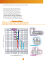
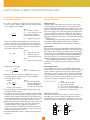
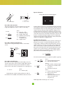
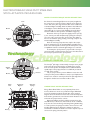
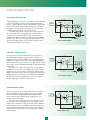
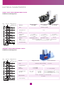
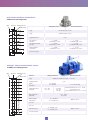
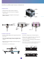
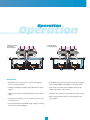
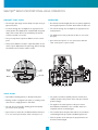
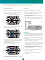
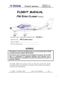
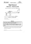
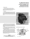
Electrohydraulic Valves...
A Technical Look
ELECTROHYDRAULIC VALVE APPLICATIONS
Moog Inc. was the founded in 1951 by William C. Moog,
inventor of the Electrohydraulic Servovalve.
His creation heralded a new era in precision control. It
also spurred the growth of Moog to become the world leader
in design and manufacture of electrohydraulic control products
and systems. During the past decade the company has extended
its control expertise into Servo-Proportional Valves, Servo
Electronics and Direct Drive Valves.
Moog products provide precise control of position, velocity
and force – so important to the proper operation of a wide
variety of industrial machinery.
APPLICATIONS
For example:
➣ Moog Inc. Servoactuators accurately control the thickness
of steel slabs in continuous casting operations.
➣ Moog Inc. ServoJet® Servo-Proportional Valves control both
velocity and pressure in plastic injection molding machines
and wall thickness in plastic blow molding machines.
➣ Moog Inc. Direct Drive Valves control the thickness of paper
on new “state of the art” paper machines.
Industrial
Mobile/Marine
Basic Metal Processing
Blow/Injection Molding
Earthquake Simulation
Entertainment Equipment
Fatigue Testing
Flight Simulation
Gas, Steam & Hydro Turbines
Machine Tools
Manufacturing Systems
Material Testing
Paper Machines
Robotics
Rubber Processing
Saw & Veneer Mill Machines
Steel & Aluminum Mill Equipment
Active Suspension
Forestry Machines
Mining Machinery
Railroads
Remote Control
Seismic Exploration
Ships
Submersibles
Vibration Reduction
ENGINEERING ASSISTANCE
The information contained in this catalog presents typical
products offered by Moog; our true expertise is helping you solve
your motion control problems. Our engineering staff is available
to assist you in your efforts to accurately and precisely control
position, velocity or force in your specific application. Often times
this results in designing a customized design and product, specifically suited to your need. Moog’s capabilities in this respect are
unmatched in industry. So call us and let us know how we can
help… you will be glad you did.
Due to our policy of continual research and improvement,
we reserve the right to change specifications in this catalog
without notice.
Applications
Applications
Each of these applications involves precise control of a complex structure, which in most cases is subject to varying loads
that can adversely affect performance. Moog products overcome
the structural and load variation effects through the principles
of feedback. Moog transducers measure the output, which could
be position, velocity, pressure or acceleration and send signals
to the machine controller.These signals are compared with the
desired output.The sensing and correcting on a continuous basis
results in optimum system performance.
2
ELECTROHYDRAULIC VALVE SELECTION GUIDE
Moog offers the broadest line of Electrohydraulic Valves on
the market today. Our product line consists of Servovalves
(Mechanical and Electric Feedback versions) and ServoProportional Valves (Direct Drive and Two Stage ServoJet®
versions). Servovalves typically utilize a ISO10372 mounting
pattern and are nearly always zero lapped or axis cut (no
mechanical deadband). Servo-Proportional Valves utilize an
ISO4401 mounting pattern and may have a mechanical deadband.
Selection of the proper valve involves understanding the
performance requirements of your application.The chart below
attempts to categorize the more popular Moog valve series by
two very important selection criteria – flow and dynamic response.
Selection
Selection
1000
D665
500
400
300
D68X
D664
D663
79-200
200
79-200 HR
D662
FLOW WITH 1000 psi SERVOVALVE DROP - gpm
100
70
72
DDV VALVE
50
79-100
D661
40
30
D634
20
G761/D765 STD
D765 HR
10
7
D765 SHR
5
4
3
SERVOVALVE
2
1
0.7
G631
D633
0.5
0.4
0.3
0.2
5
7
10
20
30
40
50
70
100
200
300 400 500 700
1000
SERVOJET®
FREQUENCY OF SERVOVALVE 90˚ PHASE LAG – Hz
(SMALL TO MEDIUM SIGNAL RESPONSE)
3
HOW TO SELECT A SERVO OR PROPORTIONAL VALVE
DETERMINE THE REQUIRED VALVE FLOW RATE AND
FREQUENCY RESPONSE
KEY PARAMETERS FOR SERVO OR PROPORTIONAL
VALVE SELECTION
a) In order to compensate for unknown forces, size the actuator
area to produce a stall force 30% greater than the desired force
to the supply pressure available.
Supply Pressure
Servovalve and ServoJet® Valves are intended to operate with
constant supply pressure and require continuous pilot flow to
maintain the hydraulic bridge balance.The supply pressure should
be set so that the pressure drop across the valve is equal to onethird of the supply pressure.The flow capacity should include the
continuous pilot flow to maintain the hydraulic bridge balance.
Direct Drive Valve performance is constant no matter what the
supply pressure.Therefore, they are good in systems with fluctuating
supply pressures.
Standard Moog Inc. valves will operate at supply pressures
from 200 to 3,000 psi. Optional valves for 50 to 5,000 psi
operation are available. Refer to individual valve specifications.
A=
1.3 FR
PS
where:
A = actuator area (in2)
FR = force required to move
the load (lb) at maximum
velocity, ref. key parameters
PS = supply pressure (psi)
Refer to the NFPA standard cylinder bore and rod sizes and
select the area closest to the result of the above calculations.
b)From the maximum required loaded velocity and the actuator
area from the above calculation, determine the valve loaded
flow and the load pressure drop.
where:
QL = loaded flow (in3/sec)
XL = maximum required
loaded velocity (in/sec)
QL = AXL
PL =
Type of Fluid
Moog Inc. valves operate most effectively with fluids that exhibit
a viscosity of 60 to 450 SUS at 100˚F. Due to the Servovalve operating range of -40˚F to 275˚F, care should be taken to assure fluid
viscosity does not exceed 6,000 SUS. In addition, fluid cleanliness is
of prime importance and should be maintained at ISO DIS 4406
Code 16/13 max, 14/11 recommended. Consult the Moog Inc.
Filtration and Valve Series catalogs for recommendations.
Fluid compatibility with material used in the construction
of valves must be considered. Contact the factory for specific
information.
where:
PL = load pressure drop (psi)
FR
A
c) Compute the no-load flow.
PS
PS - PL
QNL = QL
Force Requirements
In most applications, a portion of the available supply pressure
must be used to overcome some force. Since valve flow ratings are
given as a function of pressure drop across the valve, total force
requirements must be known in order to determine what portion
of the supply pressure is available to be dropped across the valve.
Total force is the summation of all individual forces that occur due
to the static or dynamic configuration of the system.
where:
QNL= no-load flow (in2/sec)
d)Determine the valve rated flow at 1,000 psi valve drop for
Servovalves and 150 psi valve drop for Proportional Valves.
Increase by 10% for margin.
10% pad
QR = 1.1
(
QNL
3.8
)
in3/sec to gpm conversion
where:
QR = Servovalve rated flow
(gpm) at 1,000 psi drop
or Proportional Valve
rated flow at 150 psi drop
FR = FL + FA + FE + FS
FR
FL
FA
FE
FS
e) For open-loop control, a valve having a 90˚ phase lag at 3 Hz
or higher, should be adequate.
f) For closed loop control of systems utilizing electrical feedback,
calculate the load natural frequency using the equations in this
brochure under “Load Resonant Frequency”.The optimum performance will be achieved if the Servovalve 90˚ phase point exceeds
the load resonant frequency by a factor of three or more.
g) With a calculated flow rate and frequency response, reference
the Valve Selection Table on page 3 for valve selection. Any
Servovalve that has equal or higher flow capacity and
response will be an acceptable choice. However, it is preferable not to oversize the Servovalve flow capacity as this will
needlessly reduce system accuracy.
h)Consult individual data sheets for complete valve performance
parameters.
where:
= total required force (lb)
= force due to load (lb)
= force due to acceleration (lb)
= force due to external disturbance (lb)
= force due to seal friction (lb)
Force Due to a Load
Force due to a load FL can be an aiding or resistive component,
depending upon the load’s orientation and direction of travel.
Consideration has to be taken when computing FL to ensure the
proper external friction coefficients and resolved forces are used.
WL
RESISTIVE
LOAD
PISTON
EXTENDING
4
WL
AIDING
LOAD
PISTON
RETRACTING
Dynamic Response
WL
WL
TYPICAL BODE PLOT OF DYNAMIC RESPONSE
4
250
225
FL
Ø
FL = mWL
WL = weight of load (lb)
m = coefficient of friction
FL = mWLcosØ (lb)
0
200
175
-4
150
125
-8
-12
-16
Force Due to Acceleration
The forces required to overcome inertia become very large
in high speed applications and are critical to valve sizing.
FA = Ma
VMAX
a=
Ta
M=
WL + WP
g
where:
M = mass (lb - sec2/in)
a = acceleration (in/sec2)
WP = weight of piston (lb)
VMAX = maximum velocity (in/sec)
Ta = time period for
acceleration (sec)
WL = weight of load
CONSTANT
KA =
FE
PRESS
MAX
50
100
KO KS (lb/in)
KO + KS
The load resonant frequency for an equal area cylinder is given by:
INTERMITTENT
ƒN =
Force Due to Seal Friction
Most valves are used on applications which employ some sort
of motion device.These motion devices usually utilize elastomer
seals to separate the various pressure chambers.The friction
between these seals and the moving parts acts as opposing force.
FS = 0.1 F
20 30
Load Resonant Frequency
Open loop control consists of a human operator monitoring the
parameter (i.e., position or speed) and varying the input of the
control valve to obtain the desired result. Closed loop control is
capable of fast, more accurate control and requires a high performance control valve. For optimum performance, the valves 90˚
phase point should exceed the load resonant frequency by a factor
of three or more. Load resonance is determined by the overall
stiffness (KA), which is the combination of the hydraulic stiffness
(KO) and the structural stiffness (KS), given by:
EXTERNAL
COMPRESSION
OR TENSILE
FORCE
DEFORMATION
FORCE
10
90
75
50
25
0
200 300 500
Hz
A valve’s dynamic response can be easily determined by measuring
the frequency at which the phase lag between the input current
and output flow reaches 90˚ (90˚ phase lag point).The frequency
response will vary with input signal amplitude, supply pressure,
and fluid temperature.Therefore, comparisons must use consistent data.The recommended peak-to-peak signal amplitude is 80%
of the valve rated current. Servovalve and ServoJet® response will
improve somewhat with higher supply pressure, and generally
depreciate at both high and low temperatures. Direct Drive Valve
response is independent of supply pressure.
Force Due to External Disturbances
These forces can be generated by constant or intermittent
sources.
FE
5
Degrees(˚)
FL
KO =
1
2¹
4s ßA
XT
where:
F = stall force (lb)
MAX
s =
Standard practice involves setting seal friction at 10% of
the maximum force available, unless absolute values are known.
AXm
V
KO
M
where:
ƒN = load resonant frequency (Hz)
KO = hydraulic stiffness (lb/in)
where:
ß = bulk modulus of fluid used (psi)
A = working area of double ended
piston (in2)
XT = total piston stroke (in)
where:
s = actuator volumetric efficiency
Xm = piston stroke used for
application (in)
V = total volume of fluid between
valve control ports and
the piston (in3)
NOTE:Typical bulk modulus (ß) Å 2.0 x 10⁵ psi
5
ELECTROHYDRAULIC VALVE PILOT STAGE AND
SPOOL ACTUATION TECHNOLOGIES
NOZZLE FLAPPER TORQUE MOTOR DESCRIPTION
An electrical command signal (flow rate set point) is applied to
the torque motor coils and creates a magnetic force which acts
on the ends of the pilot stage armature.This causes a deflection
of armature/flapper assembly within the flexure tube. Deflection
of the flapper restricts fluid flow through one nozzle which is
carried through to one spool end, displacing the spool. [Spool
actuation relative to valve operation is detailed on page 17]
Movement of the spool opens the supply pressure port (P)
to one control port while simultaneously opening the tank port
(T) to the other control port.The spool motion also applies a
force to the cantilever spring, creating a restoring torque on the
armature/flapper assembly.
Once the restoring torque becomes equal to the torque
from the magnetic forces, the armature/flapper assembly moves
back to the neutral position, and the spool is held open in a state
of equilibrium until the command signal changes to a new level.
In summary, the spool position is proportional to the input
current and, with constant pressure drop across the valve, flow to
the load is proportional to the spool position.
Coils
Nozzle
Armature
Feedback
Wire
Flapper
Technology
Technology
SERVOJET® DESCRIPTION
Annular
Area
Jet
Pipe
Receiver
Nozzle
Cable
Hole
Bearing
The ServoJet® pilot stage consists mainly of torque motor, jet pipe
and receiver.A current through the coil displaces the jet pipe
from its neutral position.This displacement, combined with the
special shape of the jet pipe, directs a focused fluid jet towards
one side of the receiver.
The jet now produces a pressure difference across the ends
of the spool.This pressure difference causes a spool displacement
which, in turn, results in control port flow.The pilot stage drain is
through the annular area around the nozzle to tank.
Permanent
Magnets
Coil
Armature
Centering
Springs
LINEAR FORCE MOTOR DESCRIPTION
Moog’s Direct Drive Valves use our proprietary linear force
motor. A linear force motor is a permanent magnet differential
motor.The permanent magnets provide part of the required
magnetic force.The linear force motor has a neutral mid-position
from which it generates force and stroke in both directions. Force
and stroke are proportional to current.
High spring stiffness and the resulting centering force, plus
external forces (i.e. flow forces, friction forces due to contamination), must be overcome during outstroking. During backstroking
to center position, the spring force adds to the motor force and
provides additional spool driving force making the valve less
contamination sensitive.The linear force motor requires very low
current in the spring centered position.
Plug
6
TYPES OF SERVO SYSTEMS
POSITION SERVO SYSTEM
SERVOAMPLIFIER
A load positioning servo system is comprised of a Servo, ServoJet®
or Direct Drive Valve, actuator, position feedback transducer,
position command generator, and a Servoamplifier. A typical linear
position servo system using a double-ended piston is shown to
the right (a rotary position servo system can be created by
substituting the appropriate rotary components).
The valve’s two output control ports are connected across
the load cylinder. In the Servoamplifier, the command input is
compared to the present position output of the position
transducer. If a difference between the two exists, it is amplified
and fed to the valve as an error signal.The signal shifts the valve
spool position, adjusting flow to the actuator until the position
output agrees with the command input.
null
–
+
POSITION
COMMAND
GENERATOR
error
signal
valve
driver
summing
and gain
sensitivity
SERVOVALVE
PS
C1
position feedback
C2
R
load
I
CYLINDER
–
+
POSITION TRANSDUCER
TYPICAL POSITION SERVO
VELOCITY SERVO SYSTEM
A velocity servo system is comprised of a Servo, ServoJet® or
Direct Drive Valve, hydraulic motor, tachometer, velocity command generator, and a Servoamplifier whose summing and gain
amplifier are configured to also act as an integrating amplifier.A
typical rotary servo system is shown to the right (a linear velocity
servo system can be created by substituting the appropriate linear
components).
The valve’s two output control ports are connected across
the hydraulic motor. In the Servoamplifier, the command input is
compared to the present velocity output of the tachometer. If a
difference between the two exists, it is integrated over time and
subsequently fed to the valve as an error signal.This signal shifts
the valve spool position, adjusting flow to the motor until the
velocity output agrees with the command input.
integrated
error
signal
SERVOAMPLIFIER
VELOCITY
COMMAND
GENERATOR
valve
driver
command
integrating,
summing
and gain
sensitivity
SERVOVALVE
P
C1
C2
R
load
velocity feedback
G
HYDRAULIC
MOTOR
TACHOMETER
TYPICALVELOCITY SERVO
FORCE SERVO SYSTEM
A force servo system can be created with a Servo, ServoJet® or
Direct Drive Valve, actuator, load cell or pressure transducer,
and a Servoamplifier (an Adjustable Metering Orifice may be
used to improve system performance). A typical force servo
system is shown to the right.
The valve’s two output control ports are connected across
the cylinder. In the Servoamplifier, the command input is compared to the present force output of the load cell. If a difference
between the two exists, it is amplified and fed to the valve as an
error signal.The signal shifts the valve spool position, adjusting
pressure to the actuator until the force output agrees with the
command input.
SERVOAMPLIFIER
null
+
–
FORCE
COMMAND
GENERATOR
error
signal
sensitivity
valve
driver
summing
and gain
SERVOVALVE
P
C1
AMO
C2
R
load
force feedback
LOAD CELL
CYLINDER
TYPICAL FORCE SERVO
7
GENERAL TERMINOLOGY
Per SAE ARP 490
See Moog Technical Bulletin No. 117 for a complete discussion of Closed Loop and Valve terminology and test techniques.
ELECTRICAL
Input Current – The electrical current to the valve which
commands control flow, expressed in milliamperes (mA).
Rated Current – The specified input of either polarity to
produce rated flow, expressed in milliamperes (mA). Rated current
is specified for a particular coil configuration (differential, series,
individual or parallel coils) and does not include null bias current.
Coil Impedance – The complex ratio of coil voltage to current.
Coil impedance will vary with signal frequency, amplitude, and
other operating conditions, but can be approximated by the DC
coil resistance R, expressed in ohms(½) and the apparent coil
inductance L, expressed in henrys (H), measured at a specific
signal frequency.
Dither – An AC signal sometimes superimposed on the valve
input to improve system resolution. Dither is expressed by the
dither frequency hertz (Hz) and the peak-to-peak dither current,
expressed in milliamperes (mA).
Terminology
Terminology
Units:
Recommended English and Metric units for expressing valve performance include the following:
CATEGORY
ENGLISH
METRIC
in3/sec (cis)
CONVERSION
FACTORS
liters/min (lpm)
0.98 lpm/cis
3.85 cis/gpm
3.78 lpm/gpm
bar
millimeters (mm)
0.069 bar/psi
25.4 mm/in
25400 µm/in
0.454 kg/lb
Fluid Flow
gal/min (gpm)
Fluid Pressure
lb/in2 (psi)
Dimensions
inches (in)
Weight
pounds (lb)
micrometers (µm)
kilograms (kg)
Torque
in-lb
Newton meters (N-m)
0.113 N-m/in-lb
Temperature
degrees Fahrenheit (˚F)
degrees Celsius (˚C)
˚C = 5/9 (˚F – 32)
8
Valve Pressure Drop ÆPV – The sum of the differential
pressure across the control orifices of the valve spool, expressed
in psi or bar.Valve pressure drop will equal the supply pressure,
minus the return pressure, minus the load pressure drop,
[ÆPV = (PS – R) – ÆPL].
HYDRAULIC
Control Flow QV – The flow through the valve control ports to
the load expressed in in3/sec (cis), gal/min (gpm), or liters/min (lpm).
Rated Flow QR – Servovalves are typically rated at 1,000 psi
drop, while Proportional Valves are rated at 150 psi drop.The
flow under no-load condition, QNL, will vary with supply pressure
as shown in Figure 1.The relationship can be calculated by:
PERFORMANCE
Linearity – The maximum deviation from control flow from the
best straight line of flow gain, expressed as percent of rated current.
where:
QNL = no-load flow
P
ÆP
S
Q =Q
NL
R
Symmetry – The degree of equality between the flow gain of one
polarity and that of reversed polarity. Measured as the difference
in flow gain for each polarity, expressed as percent of the greater.
PS = supply pressure
QR = Servovalve rated flow
at 1,000 psi drop, P.V.
rated flow at 150 psi drop
ÆP = valve drop, typically 1,000 psi
for Servovalves and 150 psi
for Proportional Valves
Hysteresis – The difference in valve input currents required
to produce the same valve output as the valve is slowly cycled
between plus and minus rated current.
FIGURE 1
CHANGE IN RATED FLOW WITH PRESSURE
Threshold – The increment of input current required to produce
a change in valve output.Valve threshold is usually measured as the
current increment required to change from an increasing output to
a decreasing output, expressed as percent of rated current.
200
100
ID
0 PS
100
ID
m@
S
p
P
g
0
60
100
D
m @ 00 PSI
p
g
0
1
40
D
m @ 00 PSI
p
g
10
30
SID
m @ 1000 P D
p
g
SI
25 pm @
00 P
20 g @ 10 PSID
pm 1000
g
5
1
@
pm
10 g
ID
0 PS
100
@
pm
g
5.0
ID
0 PS
100
@
m
p
g
2.5
ID
0 PS
100
@
pm
g
1.0
50
40
30
20
10
5
1
0.5
0.1
100
200
500
1000
Lap – In a sliding spool valve, the relative axial position relationship
between the fixed and moveable flow-metering edges within
the null region. Lap is measured as the total separation at zero
flow of straight line extensions of nearly straight portions of
the flow curve.
Pressure Gain – The change of load pressure drop with change
of input current at zero control flow (control ports blocked),
expressed as nominal psi/mA or bar/mA throughout the range
of load pressure between ±40% supply pressure.
Null – The condition where the valve supplies zero control flow
at zero load pressure drop.
2000 3000
Null Bias – The input current required to bring the valve to null,
excluding the effects of valve hysteresis, expressed as percent of
rated current.
5000
Flow Gain – The normal relationship of control flow to input
current, expressed as cis/mA, gpm/mA, or lpm/mA.
Null Shift – The change in null bias resulting from changes in
operating conditions or environment, expressed as percent of
rated current.
No Load Flow – The control flow with zero load pressure drop,
expressed in cis, gpm, or lpm.
Frequency Response – The relationship of no-load control flow
to input current when the current is made to vary sinusoidally at
constant amplitude over a range of frequencies. Frequency response
is expressed by the amplitude ratio in decibels (db) and phase
angle in degrees (˚) over a specific frequency range.
Internal Leakage – The total internal valve flow from pressure to return
with zero control flow (usually measured with control ports blocked),
expressed in cis, gpm, or lpm. Leakage flow will vary with input current,
generally being a maximum at the zero level of null (called null leakage).
Load Pressure Drop ÆPL – The differential pressure between
the control ports (that is, across the load actuator), expressed in
lbs/in2 (psi) or bar.
9
HYDRAULIC CHARACTERISTICS
Rated Flow: See Figure 1. page 9.
Frequency Response: Servo or Proportional Valve frequency
response will vary with signal amplitude, supply pressure, and
internal valve design parameters.The typical response varies with
supply pressure as expressed by the change in frequency of the
90˚ phase point, as shown in figure 2. Note that Direct Drive Valve
response is independent of system pressure.
Internal Leakage: There are two sources of internal leakage;
first, flow through the hydraulic amplifier (known as “tare flow”)
which is relatively constant, and second, flow around the spool
which varies with its position. Maximum internal leakage occurs
at null. See individual Servo and Servo-Proportional Valve catalogs
for specifications.
Step Response: Servo or Proportional Valve step response will
vary with amplitude, supply pressure and internal valve design
parameters. See individual series catalogs for specifications. Full
amplitude step responses will normally exhibit a straight line
portion which represents flow saturation of the pilot stage.The
slope of this straight line portion will vary with the square root
of the change in supply pressure.
Spool Driving Forces: The maximum hydraulic force available
to drive the second-stage spool will depend upon the supply
pressure, multiplied by the end of the spool. In the case of
Direct Drive Valves, spool driving force is created by the linear
force motor and does not change with supply pressure.
FIGURE 2
FREQUENCY RESPONSE CHANGE
WITH PRESSURE
FIGURE 3
CHANGE IN CONTROL FLOW WITH
CURRENT AND LOAD PRESSURE
1.5
100
Fp
natural frequency at other pressures
=
Fref natural frequency at 3,000 psi (210 bar)
1.4
100% INPUT CURRENT
80
CONTROL FLOW–% RATED FLOW
1.3
1.2
1.1
1.0
Fp
Fref 0.9
0.7
0.6
0.5
75%
60
Null Bias: Input current to the valve required to adjust the
output to zero flow. Most Moog Inc. valves have mechanical
adjustments which allow the null bias to be externally adjusted.
50%
40
25%
20
-100 -80
0.8
Pressure Gain: A measure of the change in control port pressures
as the input current is varied about the zero flow point. Pressure
gain is measured against a blocked load under no flow conditions.
Normally the pressure gain exceeds 30% of the supply pressure
for 1% change in rated current and can be as high as 100%.
-60 -40
-20
-20
-40
-60
-80 -100
-20
25%
-40
50%
75%
0.4
-60
-80
100%
-100
LOAD PRESSURE DROP–% SUPPLY PRESSURE
0.3
0
1000
2000
3000
04000
LINEAR SCALE SUPPLY PRESSURE (PSI)
5000
Flow–Load Characteristics: Control flow to the load will
change with various combinations of load pressure drop and
electrical input, as shown in figure 3.These characteristics closely
follow the relationship.
where:
QNL = no-load flow at
1,000 psi drop for
Servovalves and
150 drop for P.V.
i
QL = QNL i
PV
= actual/rated current (%)
PV = (PS – PR) – PL
PS = supply pressure
PR = return pressure
PL = load pressure drop
QL = control flow
to the load
10
PERFORMANCE CHARACTERISTICS
PERFORMANCE CHARACTERISTICS
Flow Gain: The no-load flow characteristics of Servo or
Proportional Valves can be plotted to show flow gain, symmetry
and linearity.Typical limits (excluding hysteresis effects) are shown
in Figure 4.
Linearity: The nonlinearity of control flow to input current will be
most severe in the null region due to variations in the spool null
cut.With standard production tolerances, valve flow gain about null
(within ±5% of rated current input) may range from 50 to 200% of
the normal flow gain.
Rated Flow Tolerance: ±10%
Symmetry: < 10%
Hysteresis: typically < 3% for servovalves, < .3% for proportional valves
Threshold: typically < .5% for servovalves, < .1% for proportional valves
Null Shift:
With temperature: 100˚F variation (56˚C) < ±2%
With acceleration: to 10 g < ±2%
With supply pressure: 1,000 psi change (70 bar) < ±2%
Characteristics
Characteristics
FIGURE 4
±10% LIMITS
100
IE
D
G
SP
EC
IF
0%
50
%
SP
EC
20
40
20
-60
-40
-20
20
40
60
80
20
100
-20
-40
-60
50
%
-80
0%
-100
20
CONTROL FLOW–% RATED
AI
IF
60
N
IE
D
G
AI
N
80
-20
-80
-100
INPUT CURRENT–% RATED
11
20
-20
ELECTRICAL CHARACTERISTICS
INTRODUCTION
Moog’s many electrohydraulic valve designs employ a number of
different electrical connections. Mechanical Feedback Valves utilize
the simplest electrical connections, while Electrical Feedback
Valves can be more complex with different command signals,
supply voltages and techniques to monitor actual spool position
being employed. All Moog valves can be segmented into the
following categories:
Valve Style
Electrical Connection
Mechanical Feedback Servovalve
4 pin
Electrical Feedback Servovalve
6+PE pin
Direct Drive Servo-Proportional Valve
6+PE pin
6+PE pin
ServoJet® Servo-Proportional Valve
ServoJet® Servo-Proportional Valve
11+PE pin
DDV Pilot Servo-Proportional Valve
6+PE pin
DDV Pilot Servo-Proportional Valve
11+PE pin
Coil Connections: A four pin electrical connector that mates
with a MS3106R14S-2S or equivalent is standard. All four coil
leads are available at the connector, allowing external connections
for signal, series, or parallel coil operation.
Command Signal
Current
Voltage or Current
Voltage or Current
Voltage or Current
Voltage or Current
Voltage or Current
Voltage or Current
Dither: A small amplitude, high frequency sinusoidal signal may
be used to reduce friction and hysteresis effects within the valve,
improving system performance. If used, the peak-to-peak amplitude should be less than 10% of rated signal. Since the desired
frequency is dependent on the valve style, consult factory for
recommended frequency.
Coil Impedance: The two coils in each Servovalve are wound
for equal turns with a normal production tolerance on coil
resistance of ±12%. Copper magnet wire is used, resulting in a
coil resistance that will vary significantly with temperature.The
effects of coil resistance changes can be essentially eliminated
through the use of a current feedback Servoamplifier having high
output impedance.
Inductance is determined under pressurized operating conditions and varies greatly with signal frequencies above 100 Hz.
MECHANICAL FEEDBACK VALVE
ELECTRICAL CHARACTERISTICS
Rated Current and Coil Resistance: The specified input of
either polarity to produce rated flow, expressed in milliamperes
(mA). Rated current is specified for a particular coil configuration
(differential, series, individual or parallel coils) and does not
include null basis current.
Intrinsically Safe: Optional intrinsically safe designs are available
for most standard valve models.These designs have been granted
both entity and loop approval by Factory Mutual (FM), CSA and
Cenelec. Please consult factory for the latest CSA information on
hazardous location approvals.
Mechanical Feedback Standard Electrical Configuration:
Standard electrical connections and electrical polarity for flow
out of left control port when viewing valve from pressure side
area are:
single coil:
series coil:
parallel coils:
Servoamplifier: A Servovalve responds to input current.
Therefore, in order to reduce the effects of coil resistance
variations, a Servoamplifier with high internal impedance
(as obtained with current feedback) should be used.
A+, B-; or C+, Dtie B to C; A+, Dtie A to C and B to D;
[A & C]+, [B & D]-
ELECTRICAL CONNECTIONS
Connector MS3106R14S-2S
Parallel
A
Connectors for Valve Opening
P ➧ B,A ➧ T
B C
Series
D
A
A and C (+)
B and D (-)
B C
Single
D
A (+), D (-)
B and C connected
12
A
B C
D
A (+), B (-)
or C (+), D (-)
ELECTRICAL FEEDBACK VALVE
ELECTRICAL CHARACTERISTICS
Supply Voltage: An electrical feedback always employs an
on-board position transducer and often times has the valve
control electronics on-board.Thus Electrical Feedback Valves
require a supply voltage. Supply voltages for some models are
24 VDC (19 VDC min. and 32 VDC max.), while others require
±15 VDC (±3%).
6+PE Electrical Configuration: Moog offers up to three
configurations of electrical connections for its Electric Feedback
Valves. See page 14 for details.They are available on:
Input Signals: There are two basic options for command signals
for Electric Feedback Valves – voltage and current. Each valve
series may offer different options, so consult individual data sheets
for choices. For voltage commands, the spool stroke of the valve is
proportional to differential input (VD and VE).The valve is opened
100% (opening P ➧ A and B ➧ T) by a maximum voltage (VD - VE)
command. A voltage command that is in the midpoint of the
voltage command range results in the spool being centered. If
only one command signal is available, pin D or E is connected to
signal ground. For current commands, the spool stroke of the
valves is proportional to ID or IE.The valve is opened 100%
(opening P ➧ A and B ➧ T ) by a maximum current (ID - IE).
A current command that is in the midpoint of the current
command range results in the spool being centered.
11+PE Electrical Configuration: Moog also offers a
11+PE connector for its D660, D680 and D691 Series Valves.
This connector allows additional monitoring of the valve,
including dequate supply voltage and position error logic.
See page 14 for details.
Measuring Spool Position: Electric Feedback Valves permit
the monitoring of actual spool position by measuring the signal
from pin F.The output signal can be either current or voltage.
Check individual valve series data sheets for specific options. The
amplitude of the output signal is proportional to spool position.
– Direct Drive Servo-Proportional Valves
– ServoJet® Servo-Proportional Valves
– Electrical Feedback Servovalves
Shielding: All signal lines should be twisted pairs and shielded.
Shielding connected radially to z (0 V), power supply side, and
connecting to the mating connector housing (EMC) should
be used.
EMC: All Electrical Feedback Valves, that employ on-board
or integrated electronics; meet the requirements of
EN 55011/3.91 class B, EN 50081-1/01.92, and EN 500822/03.95 performance criterion class A.
Explosion Proof: Valves are available with explosion proof
protection to EN 50018, class EEx d II C-C2H2T5.
systems
systems
13
ELECTRICAL CHARACTERISTICS
DIRECT DRIVE SERVO-PROPORTIONAL VALVES
6+PE Electrical Configuration
Valve
Connector
Mating Connector
Cabinet Side
Function
Voltage Command
0…±10 VDC
Current Command
0…±10 mA
+24 VDC (22 to 28 VDC)
Supply
A
B
^ (0 V)
Supply/Signal Ground
C
Current Command
+4…+20 mA
Not Used
D
Input Command
Valve Flow
0…±10 VDC
Input Resistance = 50 k½
0…±10 mA
Load Resistance = 200 ½
+4…+20 mA
Load Resistance = 200 ½
E
Input Inverted Command
Valve Flow
0…±10 VDC
Input Resistance = 50 k½
0…±10 mA
Load Resistance = 200 ½
Not Used
F
Output
Actual Spool Position
PE
100% flow out port B @ +4 mA
100% flow out port A @ +20 mA
Load Resistance 300 to 500 ½ with respect to ^ (0V)
Protective Grounding
SERVOJET® SERVO-PROPORTIONAL VALVES
6+PE Electrical Configuration
Valve
Connector
Mating Connector
Cabinet Side
Function
Voltage Command
24 VDC (min. 19 VDC, max. 32 VDC)
Supply
A
B
Imax: 300 mA
^ (0 V)
Supply/Signal Ground
C
Current Command
VC-B > 8.5 VDC
VC-B < 6.5 VDC
Enabled
Not Enabled
Ie = 1.2 mA at +24 VDC
D
Input Rated Command
(differential)
E
VD-E: 0…±10 V
Re: 10 k½
F
VD-B and VE-B:
max.: -15 V
max.: +24 V
Input Command Referenced to ^ ID-B: 0…±10 mA
(Load Resistance 200 ½)
Input Command (Inverted) Ref. to ^ ID-B: 0…±10 mA
VF-B: +2.5…+13.5 V.At +8 V spool in centered position
Ra: ca 15 k½
Output Actual Value
PE
Protective Grounding
14
ELECTRICAL FEEDBACK SERVOVALVES
6+PE Electrical Configuration
Valve
Connector
Mating Connector
Cabinet Side
A
B
C
Function
Current Command
Voltage Command
Supply
+15 VDC ±3%, ripple < 50 mVpp
Supply
–15 VDC ±3%, ripple < 50 mVpp
^ (0 V)
Supply/Signal Ground
D
Input Command
Valve Flow
0…±10 VDC
Input Resistance = 10 k½
0…±10 mA
Load Resistance (diff.) = 1 k½
E
Input Inverted Command
Valve Flow
0…±10 VDC
Input Resistance = 10 k½
0…±10 mA
Load Resistance (diff.) = 1 k½
F
Output Actual Value
Spool Position
0…±10 VDC
Load Resistance = 1 k½
0…±10 mA
Load Resistance max. = 500 ½
PE
Protective Grounding
SERVOJET® SERVO-PROPORTIONAL VALVES
11+PE Electrical Configuration
Valve
Connector
Mating Connector
Cabinet Side
Function
Voltage Command
24 VDC (min. 19 VDC, max. 32 VDC)
Supply
1
2
Current Command
^ (0 V)
Supply/Signal Ground
V3-2 > 8.5 VDC
V3-2 < 6.5 VDC
Enabled
Not Enabled
3
Ie = 1.2 mA at +24 VDC
4
Input Rated Command
(differential)
5
Imax: 300 mA
V4-5: 0…±10 V
Re: 10 k½
V4-2 and V5-2:
max.: -15 V
max.: +24 V
Input Command Referenced to ^ I4-2: 0…±10 mA
(load resistance 200 ½)
Input Command (Inverted) ref. to ^ I5-2: 0…±10 mA
6
V6-7: 0…±10.5 V
Ra: ca 20 k½
Output Actual Value
(differential)
7
V8-2 > 8.5 VDC: ok
V8-2 < 6.5 VDC: not ok
Enable and Supply
Acknowledged
8
9
Output Imax: 20 mA
Not Used
10
Not Used
11
V11-2 > 8.5 VDC: < 30%
V11-2 < 6.5 VDC: > 30%
Position Error, Logic
PE
Protective Grounding
15
Output Imax: 20 mA
NOZZLE FLAPPER SERVOVALVE OPERATION
TORQUE MOTOR
Upper
Polepiece
➣ Charged permanent magnets polarize the polepieces.
➣ DC current in coils causes increased force in diagonally
opposite air gaps.
N
➣ Magnetic charge level sets magnitude of decentering force
gradient on armature.
Armature
S
Lower
Polepiece
Permanent
Magnet
N
N
N
S
S
S
Permanent
Magnet
Flux
➤
N
Permanent
Magnet
Attractive
Force
S
➤
➤
N
Torque to
Rotate
Armature
➤
Coil
S
Coil Flux
HYDRAULIC AMPLIFIER
VALVE SPOOL
➣ Armature and flapper rigidly joined and supported by thin-wall
flexure sleeve.
➣ Spool slides in bushing (sleeve) or directly in body bore.
➣ Bushing contains rectangular holes (slots) or annular grooves
that connect to supply pressure PS and tank T.
➣ Fluid continuously flows from pressure PS, through both inlet
orifices, past nozzles into flapper chamber, through drain orifice
to tank T.
➣ At “null” spool is centered in bushing; spool lobes (lands) just
cover PS and T openings.
➣ Rotary motion of armature/flapper throttles flow through one
nozzle or the other.
➣ Spool motion to either side of null allows fluid to flow from PS
to one control port and from other control port to T.
➣ This diverts flow to one end of the spool.
Spool at Null
Spool
Feedback Spring
Bushing
ARMATURE
T
Ps
T
Ps
FLAPPER
INLET
ORIFICE
FLEXURE
SLEEVE
A
PS
B
PS
Spool Dispaced to Left
T
T
Ps
T
Ps
Æ
A
16
B
Operation
Operation
Valve Responding
to Change in
Electrical Input
Valve Condition
Following Change
N
N
N
N
N
S
S
S
PS
PS
T
S
S
PS
PS
T
T
PS
PS
PS
DPL
A
T
PS
Flow to Actuator
A
B
B
OPERATION
➣ Electrical current in torque motor coils creates magnetic
forces on ends of armature.
➣ As feedback torque becomes equal to torque from magnetic
forces, armature/flapper moves back to centered position.
➣ Armature and flapper assembly rotates about flexure sleeve
support.
➣ Spool stops at a position where feedback spring torque
equals torque due to input current.
➣ Flapper closes off one nozzle and diverts flow to that end of
spool.
➣ Therefore, spool position is proportional to input current.
➣ With constant pressures, flow to load is proportional to
spool position.
➣ Spool moves and opens PS to one control port; opens other
control port to T.
➣ Spool pushes ball end of feedback spring creating a restoring
torque on the armature/flapper.
17
a
SERVOJET® SERVO-PROPORTIONAL VALVE OPERATION
SERVOJET® PILOT STAGE
OPERATION
➣ The ServoJet® pilot stage consists mainly of torque motor, jet
pipe, and receiver.
➣ An electrical command signal (flow rate set point) is applied to
the integrated position controller which drives the valve coil.
➣ A current through the coil displaces the jet pipe from its
neutral position. This displacement, combined with the special
shape of the nozzle, directs a focused fluid jet from both
receivers towards one receiver.
➣ The current through the coil displaces the jet pipe from its
neutral position.
➣ The displacement of the jet directs the flow to one end of
the spool.
➣ The jet now produces a pressure difference in the control
ports.
➣ Spool moves and opens P to one control port, while the
other control port is open to tank T.
➣ This pressure difference results in a pilot flow, which in turn
causes a spool displacement.The pilot stage drain is through
the annular area around the nozzle to tank T.
Annular
Area
Nozzle
Jet
Pipe
Receiver
X T
VALVE SPOOL
➣ Spool slides in bushing (sleeve) or directly in body bore.
A
P
B
T2
Y
➣ The position transducer (LVDT), which is excited via an
oscillator, measures the position of the main spool (actual
position voltage).
➣ Bushing contains rectangular holes (slots) or annular grooves
that connect to supply pressure PS and tank T.
➣ At “null,” spool is centered in bushing; spool lobes (lands)
just cover PS and T openings.
➣ The signal for the actual position of the spool is then
demodulated and fed back to the controller, where it is
compared with the command signal.
➣ Spool motion to either side of null allows fluid to flow from
PS to one control port, and from other control port to T.
➣ The controller drives the pilot valve until the error between
command signal and spool position feedback signal is zero.
➣ Thus, the position of the main spool is proportional to the
electrical command signal.
18
DIRECT DRIVE SERVO-PROPORTIONAL VALVE OPERATION
LINEAR FORCE MOTOR
VALVE SPOOL
➣ A linear force motor is a permanent magnet differential motor.
➣ Spool slides in bushing (sleeve) or directly in body bore.
➣ The motor consists of a coil, pair of high energy rare earth
magnets, armature, and centering springs.
➣ Bushing contains rectangular holes (slots) or annular grooves
that connect to supply pressure PS and tank T.
Permanent Magnets
➣ At “null,” spool is centered in bushing; spool lobes (lands)
just cover PS and T openings.
Centering Springs
➣ Spool motion to either side of null allows fluid to flow from
PS to one control port, and from other control port to T.
Coil
Armature
➣ Without a current being applied to the coil, the magnets and
springs hold the armature at equilibrium.
P A T B X
N S
S N
OPERATION
N S
➣ An electrical signal corresponding to the desired spool position
is applied to the integrated electronics and produces a pulse
width modulated (PWM) current in the linear force motor coil.
S N
➣ The current causes the armature to move which then directly
activates the spool.
➣ When current is applied to the coil with one polarity, the flux
in one of the air gaps surrounding the magnets is increased,
cancelling out the flux in the other.
➣ The spool moves and opens pressure P to one control port,
while the other control port is opened to tank T.
➣ This dis-equilibrium allows the armature to move in the
direction of the stronger magnetic flux.
➣ The position transducer (LVDT), which is mechanically attached
to the spool, measures the position of the spool by creating an
electrical signal that is proportional to the spool position.
N S
➣ The demodulated spool position signal is compared with
the command signal, and the resulting electrical error drives
current to the force motor coil.
S N
Direction
of Armature
➣ The spool moves to its commanded position and the spool
position error is reduced to zero.
N S
➣ The resulting spool position is thus proportional to the
command signal.
S N
➣ The armature is moved in the opposite direction by changing
the polarity of the current in the coil.
19
PRACTICAL CONSIDERATIONS WHEN LAYING OUT
ELECTROHYDRAULIC CONTROL SYSTEMS
1.Power Units
Pumps:
Constant supply pressure is preferred with minimum
variation. Use accumulators with variable displacement
pressure compensated pumps. Fixed displacement pump:
constant pressure with use of accumulator is an option.
– If more than one critical system is fed from one pump,
isolate each system with check valves and accumulators
(avoids cross-talk).
– Reservoir breather: 3 to 5 micron air filter preferred
with capacity appropriate to fluid displacement.
– Temperature and pressure should be closely controlled
if good long term control accuracy is critical.
– Fluid flowing over a relief valve represents wasted energy.
– In the case where large changes of oil volume in the
reservoir occur, as with a single ended hydraulic cylinder,
it is suggested that a 3 micron low pressure element be
used as an air breather.
– Always use dirt alarms/pressure switches to enable
changing of elements at correct intervals.
– Use cheaper low-pressure flushing elements to flush the
system on start-up – remember that new oil is “dirty oil,”
having picked up contaminant in transit and packaging.
– The tank volume should be flushed through the filter at
least 50 times, changing the element when indicated by the
pressure switch (contaminate alarm), or until the system
has operated 6 to 8 hours without the need for a flushing
element change.
2.Piping and Fittings
Do not use pipe dope. (It contains fine, hard to filter, particulate.)
Use TFE tape when necessary. Do not use pipe or pipe fittings.
– Use only correct tube cutting tools, no hacksaw.
Deburr if necessary.
– Cold bending preferred.
– Descale after hot bending and welding.
Rotating joints can generate contamination.
– Flexible lines: if unavoidable use teflon, nylon or
thermoplastic lined hoses rather than rubber (neoprene)
which eventually shed particles. Place flex lines before filter,
not after.
– Use O-ring fittings rather than tapered pipe type. If pipe
fittings cannot be avoided, use Teflon tape.
4. Servo and Proportional Valve –
Characteristics of Major Importance:
– Frequency response (time constant)
– Threshold (resolution)/hysteresis
4.1 Placement:
– Mount as near as possible to the actuator to reduce
the entrapped oil volume. Oil is compressible and can
often limit servo response.
– Flexible lines between valve and actuator can be
rarely justified. As a rule of thumb they decrease
stiffness to one-third of the volume that they contain.
Additionally, they produce contamination which must
pass through the valve. Use only nylon, teflon or
thermoplastic lined hose.
4.2 Sizing:
– Select the valve size to obtain between 1/4 and
1/3 system pressure (PS) drop across the valve at
maximum velocity. If the drop across the valve is too
small, then a flow change will not take place until the
valve is nearly closed.
– Remember: to control flow the valve must drop
pressure across itself. Too large a valve is a waste, or
worse than that, it lowers system resolution.
3. Filtration
The Moog filtration philosophy is summarized as follows:
– Use a 10 to 15 micron absolute non-bypass high pressure
filter just before the Servo or Proportional Valve.
– Use a 3 micron low pressure filter in the return line,
if possible.
– Use a 3 to 5 micron low pressure filter in an off-line
filtration loop.
– Recirculate oil in reservoir more than 5 times per hour.
This is justified on the bias that:
(i) The Servo or Proportional Valve can accept the odd
particle up to 25 microns.
(ii) It is neither practical nor economical to try to clean
the oil with a small, relatively expensive, high pressure
element.The cheaper, low pressure element is many
times larger and has the potential to filter continually
and under more ideal conditions. (Steady flow and
lower velocities increase filtration efficiency.)
20
7.Servoamplifier
– The dynamics of the analog electronics are always better
than the Servovalve and spring-mass system.Therefore, they
can be neglected.
– Some digital systems, however, lack the level of dynamics
that are needed. In order to see if this is a problem, check
the following:
(i) That the update rate of the PLC is a maximum of 20
times faster than the frequency of the valve.
(ii) That the update rate of a digital-to-analog converter,
which is required for Electric Feedback Servovalves,
is faster than the valve. A rule of thumb is that the
converter should be a minimum of 20 times faster,
and preferably 100 times faster than the 90˚ frequency
of the valve.
(iii) Use of 12 and 16 bit digital-to-analog converters.
Anything slower could compromise the valves
resolution.
(iv) The last stage to the Servovalve is a current output.
– Use of compensation techniques (Proportional, Integral
or Derivative) can be reviewed when selecting the
Servoamplifier. (Note that 90% of position loops can be
handled by a straight ‘P’ controller, and the simplicity of
set up and troubleshooting a ‘P’ controller is invaluable).
– Avoid placing the amplifier close to electric motor
controllers or other components that generate high
electromagnetic fields – consider shielding if necessary.
– Interconnection to the command signal and feedback transducer should use shielded cables to minimize interference.
(Ground only the chassis end to prevent ground loops.)
5.Actuator (cylinder/motor)
– Size the area for dynamic and static forces (remembering
the 1/4 to 1/3 PS requirement of the Servo or Proportional
Valve in the dynamic case).
– Calculate the resonant frequency and adjust the actuator
areas and valve size, if necessary, to optimize accuracy.
(Increased area plus increased natural frequency improves
accuracy.)
– Recognize the 2% to 20% breakout friction of different
seals and their effect on position resolution.
– Manifolds should not contain air pockets. If they do,
you cannot flush the air out of the manifold, leading to
a “soft” system.
– Keep the cylinder full area/rod end area ratio ² 2:1 to avoid
greatly differing extend and retract velocities.
Note:
extend velocity
retract velocity
full area
=
rod end area
5.1 Actuator Connection to Load and Frame:
– There should be no free play (a practical limit in a
position loop would be 3 to 10 times less than the
required position accuracy).
– The mechanical stiffness should normally be 3 to 10
times higher than hydraulic stiffness to avoid degrading
performance.
– Gearing down decreases inertia felt at actuator and hence
increases natural frequency (and with it system response
and accuracy). However, gearing down could lower stiffness and introduce play/backlash due to the gears.
8.Conclusion
To lay out a design for a Servosystem means taking care of
minimizing lags in the control chain. (In addition to the usual
design requirements of strength, fatigue life, ease of maintenance, ease/cost of manufacture, etc.)
Lags may be caused by:
1. Free-play/backlash/stick-slip
2. Free-time constants of components
The time constant of the valve can be selected. However, the
time constant of the actuator-mass system is dependent upon
the control of hydraulic and structural stiffness and the mass
of moving parts.
6.Feedback Transducer
Closes the loop and its characteristics are of paramount
importance, e.g.:
– Linearity
– Threshold (resolution) and hysteresis
– Drift with temperature or time
– Frequency response (it must be 3 to10 times faster than
the slowest element in the system).
6.1 Transducer Placement:
– Placing at the actuator output eliminates many control
problems (by excluding secondary spring-mass systems and
play), but may not provide accuracy at the point required.
21
ROUTINE MAINTENANCE FOR SERVO AND PROPORTIONAL VALVES
7. There are two considerations in filtration for Servo and
Proportional Valves.
7.1 Particle Contamination:
Larger particles from approximately 40 microns and
upwards can lodge in the Servovalves’ pilot stage filter
screen. Particles smaller will generally pass through.
This is a last chance filter and is not intended as a
system filter. See page 20 for filtration details.
7.2 Silt Contamination:
This can, under certain circumstances, lead to seizure
of the main spool in the bushing. However, this is rare
due to the very high spool positioning forces employed.
Silt does affect valve life by eroding the sharp metering
edges on the valve spool and bushing.
1. As a general rule, hydraulic components should not be
disturbed while they are operating normally.
– This rule particularly applies to Servo or Proportional
Valves.
– They should not be removed unless trouble-shooting has
shown that they are malfunctioning.
– If the system must be “opened” (for example, adding
new pipework, hoses, valves or actuators), then the valve
should be removed, replaced by a flushing plate and the
new system start-up procedure followed.
2. If the valve must be removed, the area around the subplate
should be thoroughly cleansed using non lint producing
materials before raising the valve from the surface.
– If the valve function is critical, a spare Servo or
Proportional Valve should always be held in stock.The
spare should be fitted in place of the removed valve and
the shipping plate placed on the removed valve.The valve
should be returned to Moog Inc. for service. A newly
installed valve may develop a fault soon after fitting if care
is not taken with cleanliness.
– Where no spare valve exists the surface should then be
covered by a clean plastic sheet so as to limit the possibility of contaminants entering the system.The valve should
be returned to Moog Inc. for service.
8. Contamination Control
Contamination enters the fluid at many points:
8.1 New oil supplied from refineries contains noticeable
residue in the bottom of empty drums. Particles of 100
micron and larger are quite usual in new oil.
8.2 Filling Methods:
Contamination can enter via dirty funnels or other
unhygienic filling methods. Moog Inc. recommends a
transfer pump upstream of the 3 micron low pressure
filter. When in doubt, remove the valve, fit a flushing
block and flush the system out before refitting the valve.
8.3 Airborne Contaminants:
Many factories have very dusty air in the vicinity of the
hydraulic power unit. Sometimes the dust is corrosive. In
systems with large air flows in and out of the reservoir,
Moog Inc. recommends a 3 micron breather filter.
8.4 Airborne contaminants are also collected on the rod
end of hydraulic cylinders and are drawn into the
cylinder in varying amounts, depending on rod wiper
efficiency.These are normally collected in the 3 micron
low pressure filter.
8.5 Contaminants from rubber hose, teflon tape, metal silt
particles from wearing valves, pumps, etc. all contribute
to fluid contamination.
3. Some valves are fitted with manual override operators. Most
have null adjust screws. No other adjustments are possible
in the field, apart from the null adjustment.The style of this
adjustment varies with different valves. Consult individual
valve series data sheets for details.
4. The torque motor is a precision device. Do not attempt to
remove or dismantle. Permanent and expensive damage can
result. Likewise, do not try to remove the spool in the main
stage. Return the valve to Moog Inc. for service.
5. Moog Inc. will not partially repair a valve. Our policy is to
always return the valve to its original specification. In so doing
it will always be returned with a 24 month new valve warranty.
6. Moog Inc. Servo and Proportional Valves are used when
precision control is required.The Servovalve is a precision
instrument and consistency in performance is not possible
with “dirty oil.”
Maintenance
Maintenance
22
11. Test Equipment.
It is difficult to troubleshoot a closed loop system to isolate
which components are faulty.The simplest way to check a valve
is to use a valve tester. Moog offers valve testers for its valves.
Model M040-119 is for Mechanical Feedback Valves, while
our M040-104 Series is for both Electrical Feedback Valves
with integrated electronics and Mechanical Feedback Valves.
These testers allow the valve to be driven with a controlled
command signal, either positive or negative, from an independent
source. It allows the Servoactuator to be positioned or moved
about its stroke length and to observe proportionality between
command and speed. Measurement of the position feedback
signal can be carried out at any point along the stroke.
9. How often do I change the fluid?
Fluid change frequency depends on whether the filtration
quality is high, oil temperature is maintained at reasonable
levels, moisture condensation is low, and the oil is not breaking
down. Regular observations of oil color in the sight glass are
sufficient for monitoring the condition of the fluid. If it remains
clear and machine operation is normal, do not change the
fluid.There is no firm and fast rule for fluid change. Hydraulic
system fluids are not like the oils in engines, as they are not
subject to continuous chemical contamination. If the fluid is
scheduled to be changed at a time when filters are not
showing indication of contamination, then leave the old filter
elements in for one or two days before changing them for
new elements.Where the hydraulic power unit is dedicated
to the valve alone, it may be several years before an oil
change is necessary.Where the valve is fed from a larger
power unit which services other functions, a more frequent
change will be necessary.
10. Adjusting the Null on a Valve.
As stated in section 3, no other field adjustment exists on a
valve other than the null adjustment.This is set at the factory
and should not normally be disturbed. If a valve is indicating
an excessive null drift, it may be indicative of contamination.
The null adjustment allows the spool to be centered and thus
limit any actuator motion when the valve electrical signal is
zero. It is preferable to disconnect the valve connector when
carrying out this adjustment.With critical axis cut spools, the
null may drift slightly with temperature change and valve age.
One to two percent drift is permitted as it will be corrected
with the closed loop control in operation. For instructions on
how to adjust the null of a valve, see individual valve series
data sheets.
23
Argentina
Australia
Austria
Brazil
China
England
Finland
France
Germany
India
Ireland
Italy
Japan
Korea
Luxembourg
Norway
Russia
Singapore
Spain
Sweden
USA
Industrial Controls Division
Moog Inc., East Aurora, NY 14052-0018
Telephone: 716/655-3000
Fax: 716/655-1803
Toll Free: 1-800-272-MOOG
www.moog.com
CDL6566 Rev D 500-170 302