1
SERIAL NUMBER
.
I
15350075
This number must be mentioned in all communications concerning Dynakit.
STEREO CONTROL AMPLIFIER.
INSTRUCTIONS FOR
ASSEMBLY AND
OP.ERATION
..
,
Price
Patented
$1.00
086315
• • ••
1)
5
6
7
9
SPECIFICATIONS
Inputs:
7 pairs: RIAA magnetic phono low level,
magnetic phono high level (50,000 ohms);
Ceramic phono; NAB 71j2 i.p.s. tape head
(100,000 ohms); radio, tape, spare (250,000 ohms)
Outputs:
Constant level tape output, 8 and 16 ohm
loudspeaker outputs, center-channel loudspeaker
output, provision for headphone connection.
Controls:
Selector, Volume, Balance, Bass, Treble,
Stereo-Mono Switch, Loudness Compensation
Switch, Filter Switch, Power Switch.
Tone Control Range:
± 12 db at 50 cps and 15 kc.
Sensitivity for
Rated Output:
2.5 mv at tape head, 4 mv at low level magnetic
phono, 1 volt at high level inputs.
Power Output:
35 watts continuous, 45 watts IHF
Music Power (both channels).
Frequency Response:
Power Response:
± 0.25 db from 20 cps to 20 kc.
20 cps to 20 kc without exceeding 1% distortion
within 1 db of 17.5 watts (each channel) .
1M Distortion:
Less than 1% at 17.5 watts (each channel) .
Less than 0.2% on any input at average
listening levels.
Hum and Noise:
70 db below rated output on low level inputs.
80 db down on high level inputs.
Tube Complement:
Silicon Diodes:
12AX7/ECC83 (2), 7199 (2),
6BQ5/EL-84/7189 (4).
500 MA, 1000 PIV (2).
Power Consumption:
110 watts, 120 volts 60 cycle AC, or 120/240 volts
50/60 cycle AC with optional PB-028
power transformer.
Special Features:
Attractive Champagne-gold anodized aluminum
front panel and die-cast knobs; 2 AC convenience
outlets; provision for headphone output or
center-channel level control; center speaker
output; power transformer sealed in special
encapsulating material for coolest,
quietest operation.
INSTRUCTIONS FOR ASSEMBLY AND OPERATION OF
THE DYNAKIT SCA-3S STEREO CONTROL AMPLIFIER
The SCA-35 is a high quality stereo preamplifier and
amplifier combination which serves as a control center for
various program sources such as phonograph, tape and
radio. The SCA-35 permits selection of the program source
desired, modification of the tonal characteristics of the
sound source, and change of volume; it provides output connections for loudspeakers and headphones.
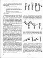
The connection of various types of program sources is
made on the back panel through the several sockets provided. The shielded audio cable'S and plugs supplied with
the program source equipment are used for connection between these components. There are screw terminals for
connection of loudspeakers to the unit. The upper row of
inputs and outputs is used for the left channel, and the bottom row for the right channel.
duced into the music when the volume control is at the
mid-point or below. At high settings of the volume control,
the loudness switch has no effect. The reason for this feature is that the human ear has decreased sensitivity to low
frequencies at low volume levels, and the loudness switch
helps to correct for this. It will add a fullness to low level
music which can enhance its pleasure.
Balance Control
.Jeledor Switch
The balance control is used to equalize the signals at the
two loudspeakers, which helps to center the sound. Turning
the balance control to the left will diminish the sound to
the right speaker, thus making the sound source move to
the left. Turning to the right will move the sound source
to the right.
Normally the balance control is centered when it is in
the mid-point (12 o'clock), but differences in programming, in speaker efficiencies, in room acoustics, and in component tolerance in the SCA-35 may require a setting off
the mid-point. Since the effects of this control are very
gradual in the area of rotation from 9 o'clock to 3 o'clock,
offsetting it in this region does not indicate abnormality.
When rotated to either extreme, the balance control cuts
off one speaker completely. This can be used if different
signals appear in the two stereo channels (such as the
reverse track of a mono tape machine), and the two are
not wanted simultaneously.
•
Tone Controls
FRONT PANEL CONTROLS
The front panel controls have been designed to make thf:
operation of the SCA-35 simple and obvious while providing suitable flexibility. Although it is possible to enjoy
use of the SCA-35 using only the power and selector
switches and the volume control, knowledge of the function
of the other switches and controls can provide increased
listening pleasure. Each of these will be described briefly.
Rotation of the selector switch to the marked positions
permits use of the marked input source. After switching to
"phono" for example, start the record player, and its signal
will be available to you.
The stereo-mono switch beneath the selector switch
extends its utility. For stereo signal sources, leave the
switch in the "stereo" position. When a mono source is
being played, the "mono" position of the switch brings this
single channel signal through both loudspeakers. When
playing monophonic recordings with a stereo cartridge, the
"mono" position eHminates most of the vertical noise components of the signal. When a stereo FM tuner is tuned to
a monophonic station, the "mono" position of the switch
frequently eliminates noise and distortion.
Volume Control
Clockwise rotation of the volume control increases the
level of the signal through both loudspeakers: The normal
setting of the control will depend on the efficiency of the
loudspeakers and the size of the signals from the cartridges
and/or tuners. It should be recognized that the position of
the control is not related to the power level at which music
is played-you may have a wide range of settings to give
a specific sound level. Adjustment should be made to the
loudness level desired without regard to the position of the
knob pointer.
If the tuner, or other input equipment, has its own level
setting or volume control, this should be set so that when
. . .witching from one input to another, the sound is close to
~e same loudness.
.
Beneath the volume control is the loudness switch. When
it is switched to "loudness" there is additional bass intro-
The bass and treble controls operate in similar fashion
with the treble control affecting high frequencies, and the
bass control the low frequencies. Each of these gives "flat"
response without frequency discrimination when the pointer
is at 12 o'clock. Clockwise rotation provides boost, and
counter-clockwise rotation gives attenuation.
When program sources are harsh or strident, treble attenuation will improve the sound. If there is boominess, bass
attenuation should be used. Some thin sounding material
can benefit from bass boost. These controls should be set to
whatever position sounds best, but it should be remembered
that departures from "flat" are of a corrective nature; and the
user should not get in the habit of listening to a corrected
tonal characteristic.
Beneath the tone controls is the filter switch. When this
is in the "filter" position it gives a narrow band response,
attenuating both high and low frequencies simultaneously.
This should be used with poor program material, such as
scratchy records, excessive rumble, noisy radio broadcasts,
and so on. By attenuating at both ends of the spectrum,
it does not create a shift in overall tonal balance. It can be
used in Conjunction with the tone controls for great
extremes of tonal correction.
Power Switch
The power switch has the obvious function of turning
the SCA-35 on and off (along with any equipment in the
switched outlet on the back panel). Allow about 15 seconds
for warmup after turning this switch to "power."
3
BACK PANEL CONNECTIONS
Phono Connections
through the SCA-35, the track recorded in the opposite
direction will come through one channel of the SCA-35
unless one of two expedients is used to prevent this:
(1) One cable can be removed from the unwanted chann*,
then by using the mono position of the stereo-mono swit~)
the sound will come through both speakers, or (2) Thebalance control can be turned to either extreme position to
eliminate sound through the unwanted channel.
The SCA-35 can be used for playing recorded tape, but it
cannot be used for recording with a tape deck which has no
recording preamplifier.
Either a record changer or a professional type turntable
can be used. There are three pairs of phono inputs, allowing
for use of all types of phonograph cartridges. There is a
choice of (1) low level magnetic cartridge, (2) high level
magnetic cartridge, or (3) crystal or ceramic type. Most popular magnetic cartridges are of the low level type. However,
if the cartridge is rated at more than 20 millivolts this is a
high level model, and the high level magnetic input should
be used. If you are using a low level magnetic cartridge and
find that there seems to be too much amplification when
using it in the low level phono input, then the high level
magnetic input may be used. This will reduce the total
amplification without detriment to performance. Always
read instructions which accompany the cartridge to determine whether its manufacturer has any special recommendations for its connections and use.
In many of the turntables and record changers made
today there is a separate ground wire. This should be connected to the screw on the back panel of the SCA-35 above
the phono inputs. If such a ground wire is not supplied with
yout phonograph, then it may be necessary to connect a
wire, in addition to the audio signal cables from the cartridge, from a ground point on the turntable motor or arm to
the grounding screw on the SCA-35. Normally it is not
desirable to make further ground conections to water pipes
or to an "earth" ground.
If the phono cartridge is a mono one, then it is suggested
that you COlUlcct its output to only one input (either channel). If you want to hear sound through both channels, turn
the stereo-mono switch on the front panel to its mono position to hear the program through both loudspeakers.
The spare input of the SCA-35 will accommodate any
type of high level input source which provides one volt or
more of audio signal. A second tape machine (having play- ~
back electronics huil t in) or tuner may be used in this inpue '
or a second phonograph which includes its own preamplifier.
Tape Connections
Loudspeakers
The SCA-35 can be used either with a tape machine
which has its own tape amplifier, or playback electronics, or
with a tape deck having direct output from the tape head.
If the machine has a tape playback amplifier, then the output is at a relatively high level. In this case this output is
connected to the input of the SCA-35 marked "From TAPE
AMP." If the machine is a deck only, the output is very
low and the input marked "From TAPE HD" is used.
The tape head input has very high amplification and the
required NAB 7% i.p.s. equalization for tape head playback.
Generally, when the tape head input is used, a ground wire
must be connected from a specific point on the tape deck
(see instructions supplied with tape deck) to the grounding
screw on the SCA-35. Try it with and without this ground
wire for lowest hum.
If the tape machine has a recording amplifier, you can
connect the SCA-35 to the tape machine for recording from
the phonograph or from the tuner. The high level input of
the tape recorder (not the microphone input) should be
connected to the socket marked "To TAPE RECORD."
Whatever is being played through the SCA-35 will be recorded unaffected by volume and tone controls of the SCA.
Thus you can listen to a program and adjust volume and
tone controls to suit, without affecting the signal going into
the recorder.
In the special case where it is desired to play a multitrack tape with a monophonic recording on all tracks
The SCA-35 can provide sufficient power to drive all but
the most inefficient loudspeaker systems. Check the specifications of the loudspeaker to determine its impedance.
Generally this will be 8 or 16 ohms. The speaker terminals
of the SCA-35 are marked for speakers of these values, but
these terminals will accommodate a wider range of impedances than marked. For example, the 8 ohm output can be
used for speakers of 4 to 11 ohm ratings; the 16 ohm output
can be used with speakers from 12 to 20 ohms.
The left channel loudspeaker should be connected to the
upper output strip. A pair of wires, such as # 18 lamp cord,
should be used with one wire going to the common terminal
(marked HC") and the other to the 8 or 16 ohm terminal.
The right speaker should be similarly connected to the
lower output strip. Note that the extreme left hand screws
on each strip are connected together by a wire strap.
N either of the two speakers should be connected to these
terminals. However, it is possible to connect a thiJ:d loudspeaker-as a center or remote speaker--·to these terminals.
Details on this use are given later. It is also possible to
connect headphones to the loudspeaker terminals, a subject
covered in detail later.
In any music system it is best that both loudspeakers be
identical. If this is not possible, the stereo effect may be
considerably distorted, and there will be shifting of positicA'
of sounds between the speakers in a way which is unrelat~P'
to the correct localization of those sounds.
4
Radio Connections
Radio tuners which can supply one volt or more audio
output can be used with the SCA-35. If the tuncr is FM
stereophonic, then its left output is COlmected to the upper
radio input and the right output goes to the lower radio
input of the SCA-35. If the tuncr is monophonic, it can be
connected either with a "Y" connector to both radio inputs,
or to only one input. If one input is used, you will have to
turn the stereo-mono switch to the mono position to receive
sound from both speakers.
If the tuner has separate outputs for AM and FM without its own provision for switching these, you may use one
(or both) of the radio inputs for FM and the spare inputs
for AM. Then selection of FM or AM broadcasts can be
made with the selector switch on the SCA-35.
Additional Inputs
-
L
Other Back Panel Connections
There are two AC outlets on the back panel to which the
wer cords of auxiliary equipment may be connected. One
these outlets is switched in unison with the SCA-3S when
e SCA's power switch is operated. The other outlet is not
switched and will furnish power at all times that the SCA's
power cord is plugged in. The switched outlet may be used
to power a radio tuner so that this can be turned on and off
with the SCA-3S. The lUlswitched outlet should be used for
a turntable, record changer, or tape machine. These devices
require mechanical switching and should not be switched
automatically when the SCA-35 is turned on or off.
The line cord of the SCA-35 should be plugged into a
suitable outlet furnishing nominally 120 volts, 60 cps alternating current (120 or 240 volts, 50 or 60 cycles for export
models) .
There are two knurled shafts on the back panel which are
used for hum adjustment of the two channels. Their function is explained below.
USING YOUR SCA-35
Once the associated equipment is connected to the
SCA-35 and you are familiar with the operation of the controls, you are ready to try it out.
Switch the stereo-mono switch to "mono." Then adjust
the balance so that the sound is equal from both loudspeakers. Stand slightly forward of the speakers at an
equal distance from each. Move from side to side while
trying to loea te the sound source. If the speakers are phased
correctly, the source will be in the center, when you are in
the center, and will shift smoothly to whichever speaker
you approach. If the speakers are phased incorrectly, there
will be an abrupt jump in the location of the sound, and it
will shift suddenly from one side to the other with little
or no apparent centering.
To correct the phasing of the loudspeakers, if it is incorrect, you must interchange the two wires between the
SCA-35 and one of the speakers. This can be done either at
the amplifier or at the speaker.
Ventilation
,
When using the SCA-35 it is essential that it have adequate ventilation. This unit dissipates 110 watts of heat,
and you can see that there is the same heating effect as
with a 110 watt incandescent lamp in a small metal container-the case will get quite watm to the touch, and
should have air space above to permit the heat to dispell.
There should always be several inches of air space above the
unit and behind it. Never place anything directly on top
of the cover when the amplifier is operating.
Hum Adjustments
Turn the volume down low, set the selector switch on
"phono," and turn on the SCA power switch. After the first
5 seconds, advance the volume control slowly until you
v ear some hum from the loudspeakers. Then turn the balance control to cutoff the right loudspeaker, and adjust the
left hum control (on the back panel) for minimum hum.
Repeat this with the balance control set to cut off the left
loudspeaker, adjusting the right channel hum control.
These controls should give some minimum point {or hum;
and this point should be low enough to be inaudible at
normal listening levels.
Turn the volume down, place a record on the turntable,
and advance the volume until you have a suitable level;
then you can adjust balance and tone controls to your
satisfaction.
The same setup procedure can be followed with a tape
deck, using the tape head input. The minimum hum point
will be at about the same point as with phono. If neither
phono or tape head inputs are to be used, the hum level
will be much lower, and it may be difficult to determine
where the minimum settings of the hum controls fall. In
this case, since hum should be inaudible, it is not important
whether the controls are set accurately.
Phasing Loudspeakers
For best stereo effect, the loudspeakers should be properly phased-an adjustment which is made once and can
then be left fixed. Phasing consists of arranging the polarity
{ the speaker connections so that both speakers function
In unison, moving in the same direction at the same time,
on monophonic signals.
Cabinet Mounting
The oversize front panel on the SCA-35 facilitates cabinet installations. The rubber feet are not used.
A supporting shelf installed flush with the bottom of a
3 1 :;{o" by 13Yt o" cutout in the cabinet panel is required.
A 3Y2" square ventilation cutout should be made in the
shelf to coincide with the punched-out section of the SCA
bottom plate, under the output tubes. A PBK bracket kit,
which eliminates the need for the shelf, is available directly
from Dynaco for $2.00. No C.O.D.'s please.
Adequate ventilation is imperative. The warranty does
not cover equipment which has been subject to abuse as the
result of insufficient ventilation. Cabinet installations frequently require the use of a small circulating fan, particularly where the SCA must be mounted close to a tuner, or
where vertical (face up) mounting is necessary. Under no
circumstances should the SCA be stacked immediately
above or below the Dynatuner.
CONNECTING A CENTER LOUDSPEAKER
Under some conditions it is advantageous to be able to
use a center loudspeaker which handles the monophonic
signal (sum of left and right channels) derived from the
two parts of the stereophonic signal. This center speaker
can eliminate the "hol.e-in-the-middle" effect of speakers
which are widely separated. The composite center signal
can also be used with a remote loudspeaker for monophonic
reproduction in another area. The signal for the center.
speaker is available on the back panel of the SCA-35 without need for another amplifier.
-
5
liiiiiiiiiliiiiiiililll
iiiiiiiiiiiiiil
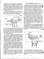
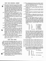
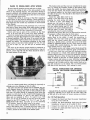
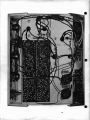
Connection of the center speaker is accomplished by
removing the wire link, or jumper, which connects the leftmost screws on the two loudspeaker terminal strips and
connecting the two wires from the extra speaker to these
two screws. The diagram below also shows how a volume,
or level setting, control can be optionally added to control
the level of the center speaker. The control itself is a 4 watt,
wirewound, potentiometer or rheostat. They are available
at all radio parts supply stores.
The control for the center speaker can be connected on
the back panel of the SCA using the hole which is available, or it can be connected at the loudspeaker locationthis is particularly convenient for a remote speaker.
__ .. ~
100fl,4W
.... -:..~--~~.
/;;':-' -
,,//i'
"
//
,,~?®\!
V
I
v~-_ll::~~-~"'l
'" /' //";/
.Jf/,//.,.....
/.
/
/.-'
-',
(~I'''
"
... _-_ .... - ...
,
CONTROL M~Y 8£
MO/JNTEO INSlbE
/
@I/
REMOVEJUMPER
WHEII CEIITER
SPEAKER IS CON·
IIECTEO
/ - - - .... CONTROl..
Ci/ASSISAS~N
I,
DR AT CEIITER
SPEAKER I.tJCA·
TIOII,
I
CENTER
SPEAKER
RIGHT
SPEAKER
LEFT
SPEAKER
It is best that all the speakers should be identical types
when using this arrangement. If this is done, the sound
level at the center speaker will be comparable with that of
the stereo speakers. The volume control will reduce the
level of the extra speaker. It can be used to reduce the level
of this speaker to zero, and then the stereo speakers will
function in their normal way.
If the control is not added, and it is desired to cut out
the center speaker to restore normal stereo operation, this
can be done by re-installing the jumper on the back panel.
This can also be done by adding a switch to connect
together the two leads to the center loudspeaker. This
switch can be located any place which is convenient - at
the speaker location, or at the amplifier. When the switch
is closed, there will be no sound from the center speaker,
and normal stereo reproduction will be obtained.
The center speaker should be phased properly. This can
be done by listening to the smoothness of transition of
sound between speakers while moving back and forth
between them. If there are sudden jumps in localization of
the sound, the two wires to the center speaker should be
interchanged. Correct phasing should provide a smooth
change in location of sound from side speakers to center
speaker. If the center speaker is used remotely, phasing is
not important.
NOTE: At any time that the center speaker is removed,
the jumper between the screw terminals must be reinstated.
If neither the jumper nor center speaker is connected, the
resulting sound will have no monophonic components.
There will be no sound with monophonic sources and
unrealistic effects with stereo sources.
6
USING HEADPHONES WITH THE SCA-35
Headphones made for high fidelity usage are generally
of the low impedance type, designed to be connected
the loudspeaker terminals of the amplifier. These can,
course, be used directly with the SCA-35 in accordance
with the instructions of the headphone manufacturer.
In addition, for ease of headphone connection and use,
a hole for a headphone jack is available on the back panel
of the SCA-35. A jack of the Switchcraft type 12B, or
equivalent, can be mounted in this hole. A type 290 plug,
or equivalent, should be used with the 12B jack. If the
headphones are supplied with a different type of plug, the
proper jack should be obtained for the plug used.
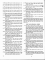
The diagram below shows the best method of connection
to the headphone jack. The 100 ohm, % watt, resistors
drop the signal to the level which is required for headphones. If there is inadequate level after installation, these
resistors can be reduced to 47 ohms, or to any specific
value recommended by the manufacturer of the headphones. Some headphones have the resistors built in. Then
it is not necessary to install them, and straight wires (insulated to avoid short circuits) .should be connected in place
of the resistors shown.
If it is desired to cut out the loudspeakers completely
for headphone listening, the pictorial diagram shows how a
double pole switch can be used to eliminate sound from
the loudspeakers during headphone use. This switch can
be mounted any place along the loudspeaker wires so that
it can be kept in a convenient place if switching is required
frequently.
'\\
SWITCH CRAFT
TYPE 128
TO
LEFT
SPEAKER
TO
RIGHT
SPEAKER
If, after the headphones are installed, it is found that
the right and left sides are incorrect and the phones are
not of a construction which can be reversed on the head,
this can be most simply corrected by disconnecting th • \I
resistors from the two jack lugs and interchanging the
connections.
-
TECHNICAL DESCRIPTION
The DYNA Stereo Control Amplifier, SCA-35, is a comlete stereo preamplifier and stereo power amplifier comed on a single chassis with a single power supply. The
SCA-35 uses new circuitry and new components in a unique
arrangement which provides highest quality performance
ill a compact and moderately priced unit. Superficial examination of the circuit of the SCA-35 might indicate an
apparently simple and conventional design. However,
closer scrutiny will reveal an extremely sophisticated and
carefully refined design.
There are four basic sections of the SCA-35: (1) the
stereo preamplifier; (2) the dQal tone control section; (3)
the stereo power amplifiers, and (4) the power supply. Each
of these utilizes novel circuitry with premium grade components conservatively operated. The four sections combine
in an inter-relationship which develops the maximum potential of these components.
The Preamplifier
The preamplifier section of the SCA-35 is a printed circuit module in which a 12AX7 tube is used for each stereo
channel. All low level inputs are fed to the input stages of
these tubes via a portion of the selector switch. High and
low level magnetic cartridges and crystaVceramic cartridges
are introduced to the input switch through a PEC
(packaged electronic circuit). The switch also selects a
tape head input. These low level signals are amplified
'through two stages (the two halves of the 12AX7). The
amplification of this tube is increased almost to its theoretical maximum by the application of positive feedback from
cathode to cathode.
A negative feedback loop containing the proper equalization circuits to shape the response of phono and tape head
is carried around the 12AX7. Operating parameters are
selected to enable this stage to carry signals at distortion
levels below 0.1 %. A 4 millivolt magnetic cartridge will
produce one volt at 1000 cps at the output of this section.
The output of the 12AX7 is fed to another section of the
selector switch, which at this point can also select higher
level inputs such as radio and tape preamplifier.
The Tone Controls
Dual tone controls are used in a network' which is completely passive; it has no distortion or noise. This network
is also a PEC in which all components are encapsulated.
Associated with the tone controls are the filter switch, the
balance control, and the volume control. Signal levels to
this section normally are about one volt (which is also the
normal output of the preamplifier stage). However, the
design is such that signals of any magnitude can be handled
without possibility of overloading the power amplifier
inputs.
he Power Amplifiers
Each power amplifier is on its individual printed circuit
module. These are truly unique circuits in which optimum
use is made of the components.
The first stage is a pentode section of a 7199 tube. This
is directly coupled to a cathodyne phase inverter. Negative
dc feedback is taken from cathode to screen to stabilize
the dc operating point of this pair. A positive feedback loop
from cathode to cathode augments the amplification of the
stage. The cathodyne inverter has the unusual advantage
that its phase inversion capabilities are dependent solely on
the values of its associated resistors. The accuracy of phase
inversion is unaffected by tube aging and similar variations.
The phase inverter drives a pair of 6BQ5 output tubes.
Careful investigation has determined the precise operating
parameters for the output tubes and output transformer.
The output transformer designed for the circuit (DYNACO
Z-565) provides maximum linearity in this configuration.
This transformer represents an advance in the state of the
art as it permits the full power of the output tubes tJ be
handled throughout the audio spectrum in a unit of very
small size. It also permits a high order of feedback with
complete stability of operation under all amplifier load
conditions.
Contrary to traditional usage, a single cathode resistor
is used for all four ou.tput tubes. This improves the performance of the output stage, but it makes it desirable to
match the four output tubes. The output tubes supplied are
carefully matched for this circuit.
The Power Supply
The SCA-35 is powered by a power transformer and full
wave rectifiers using silicon diodes. Separate heater windings are included in the power transformer to provide means
for individual hum adjustments on each stereo channel.
The power transformer is impregnated with an epoxy
resin which serves the dual purpose of heat dissipation
from the core and prevention of noise and vibration.
GENERAL WIRING PRACTICE
Assembly of the SCA-35 is exceptionally simple when
compared to that of other similar kits. The circuit boards
are supplied with all components mounted, and the remaining parts arranged on the chassis in an open, uncluttered
way that makes wiring quick and easy. The construction
of the SCA-35 should take no more than a few hours.
When you unpack the kit, check the components against
the parts list first. You can identify unfamiliar components
by matching them to parts illustrated in the pictorial
diagrams supplied.
Have the proper tools at hand before beginning to build
your kit. You will need a pencil-type soldering iron of 30to 60-watt rating; long-nosed pliers; diagonal cutters; and
a screwdriver. If you have a soldering gun, it should be used
with care, especially when working on the circuit board,
because of its higher than necessary heat output. Although
not essential, a wire-cutting and stripping tool will help
considerably; these are available for less than a dollar.
7
J
The only procedure involved in building a Dynakit
which requires a bit of technique is soldering, and this is
quite easy to master. There are four steps to making a good
solder connection:
1. Make a good mechanical connection.
2. Heat both parts of the connection with the iron.
3. Apply solder to the connection until it melts and
runs.
WRONG
4. Allow the connection to cool undisturbed.
ALL SOLDERING MUST BE DONE WITH ROSIN
CORE SOLDER.
There is no warranty on any equipment in which acid
core solder has been used. Make sure that the solder you
use is plainly marked "ROSIN CORE." Do not use cheap
solder or solder of doubtful origin. Recommended solder is
60/40 (60% tin, 40% lead) rosin core.
Whenever one (l) wire is to be soldered to a connection,
the instructions will indicate this by the symbol (S). When
two (2) wires are to be soldered to a connection, the symbol (S-2) is shown; when three (3) wires are to be soldered,
the symbol (S-3) appears, etc. There may be as many as
five (5) wires to be soldered to a connection. If no symbol
is shown, do not solder; further wiring will be made to that
connection before soldering.
Components can be identified by comparison with the
pictorial diagrams. Capacitors are individually marked.
Resistors will be marked either with their values, or with
the color code specified in the instructions. The first color
is nearest the end of the resistor, and any fourth color band
may be ignored.
A number of steps in the instructions begin, "Connect
one end of a wire ...", with the length of the wire specified.
In each case, first cut a piece of wire to the correct length
from the roll supplied with the kit, and then remove about
%" of insulation from each end before making the connection. The leads on components should be trimmed as they
are used, the length chosen being that which permits a connection to be made from point to point without strain on
terminals or components. The position of all wire leads
should follow that shown in the pictorial diagram as closely
as possible. Care must be exercised to see that uninsulated
wires do not touch each other, and cannot do so through
vibration or sagging, unless, of course, they are connected
to the same point. It is especially important that uninsulated wires and component leads or terminals do not touch
the chassis or bottom plate accidentally.
Check your work after each step, and, when you are satisfied that it has been correctly done, mark the space provided and go on to the next step. Examine the pictorial
diagrams often; if you check your work methodically, your
amplifier should work as soon as the wiring is complete.
One of the best ways to make a good mechanical connection is to bend a small hook in the end of a wire, and
then to crimp this hook onto the terminal to be connected.
The amount of bare wire exposed at the end need not be
exactly lit -inch; however, if it is too long, there is danger of
the excess touching another terminal or the chassis. There
is no need to wrap the wire around the terminal more than
one time, as this makes a connection that is much more
difficult to remove if an error has been made.
8
To transfer heat from the iron to the wire and terminal,
the tip of the iron should be kept brightly tinned with
solder. If this is properly done the first time the iron is
used, the tinning may be maintained by wiping the tip with
a cloth or sponge every few minutes while soldering. When
correctly tinned, the tip will heat both parts of the con-
nection almost immediately. Solder should then be applied
directly to the parts to be soldered, as shown in the middle
illustration above, and both iron and solder removed as
soon as the solder flows freely.
The circuit boards of the SCA-35 are supplied with all
components (resistors and cap;:lcitors) already mounted
and soldered in place. The circuit boards are connected to
the other sections of the amplifier channels by soldering
wires to eyelets on the boards. These eyelets, which are
numbered for identification, are filled with solder already.
To solder a wire to them, first "tin" the bared wire by heating it with the iron and flowing solder over it. The eyelet
is then heated with the tip of the iron, and the end of the
wire inserted as soon as the solder in the eyelet flows. A
correctly made connection looks like the illustration at th
right, above, which shows a smooth transition from eyelet
to wire.
-
fRONT PANEL MECHANICAL ASSEMBLY
1 ( /) Place the front panel before you so that its "wings"
are facing you, with the rectangular switch cutouts
at the bottom~ as in the pictorial diagram. Refer to
the pictorial diagram before and after each step to
be sure that you are proceeding correctly. Install the
pilot light socket at the extreme left end of the panel
with a #4 screw inserted from the outside, and a
lockwasher and nut from the inside (the side of the
panel which is toward you). The #4 screws are the
smallest size supplied with the kit.
2 (v'> Install the treble control (marked 167504) next to
the pilot light (see the pictorial diagram). Place a
%/f lockwasher on the shaft before inserting the
shaft through the panel, and secure it with a %"
nut. Before tightening the nut, see that the connecting lugs of the control are positioned as shown
)n the diagram.
3 ("""'" Install the bass control (167205) in the next hole.
Place a %" lockwasher on the shaft, insert the shaft,
and secure it from the outside with a %/f nut. Before tightening the nut, observe the orientation of
the connecting lugs shown on the pictorial diagram
and see that the bass control is positioned correctly.
4 (\A InstaIl the balance control (167754) in the next hole
using %" hardware and positioning the connecting
lugs as shown in the pictorial diagram.
Install the volume control (177254) in the next hole
5
with %" hardware, positioning the connecting lugs
..,.as shown in the pictorial diagram.
6( I"} The power switch is the only one of the slide
switches with only two connecting lugs. Install the
power switch from the inside, in the rectangular cutout nearest the pilot light socket so that its connecting lugs are in the position shown in the pictorial
diagram. The slide switch mounting holes are
threaded and do not require lockwashers and nuts.
Install the power switch with two #4 screws infierted from the front side of the panel.
7 ( VJ The three remaining slide switches are identical.
They should be mounted in the three rectangular
cutouts--their orientation is not important.
(v,
NOTE: The selector switch should not be installed until later. when
called lor in the instructions.
fRONT PANEL WIRING
These instructions frequently specify that you twist together some wires. This twisting should not be done too
tightly or the wire may cut through the insulation. The
twist is sufficiently tight as long as the wires are neat and
will remain together; there is no need for excessive twisting.
1(
0"Twist together two 9" green wires. Connect one end
of one wire to pilot light socket lug # 1 (8). Connect
the same end of the other wire to pilot light socket
lug #2 (8). The opposite ends of these wires will
.)ater be connected to the main chassis assembly.
2 ( v1 Twist together a 12%" and a 15/f black wire so that
they are even at one end. Connect one of the matching ends to power switch lug # 1. Connect the same
pd of the other wire to power switch lug #2.
3 (""'f Cut each lead of the .02 mid disc capacitor to 1;2/f.
A
Connect one lead of the .02 mfd disc capacitor to
~.
power switch lug #1 (8-2). Connect the other lead
to power switch lug #2 (8-2).
4 ( ~ The numbering of the lugs on the controls is shown
on the pictorial diagram. Connect one end of a 2Vz"
red wire to treble control lug #5 (8). Connect the
other end to bass control lug #5.
5( ~Connect one end of a 2 112" green wire to treble controllug #2 (8). Connect the other end to bass control lug #2.
6(
Connect one end of a 2" red wire to bass control
lug # 5. Connect the other end to balance control
lug #6(8).
7 ( ...,--connect one end of a 2" green wire to bass control
lug #2. Connect the other end to balance control
lug #1 (8).
8(..-) Twist together a 5" black and a 5/f red wire. Connect one end of the black wire to balance control lug
# 4. Connect the same end of the red wire to balance
control lug #5 (8).
9 ( ~bserve, on the pictorial diagram, the manner in
which the PEC-555002 tone control modules are
wired to the bass, treble, and volume controls. Begin
by carefully Gutting the leads of one of the circuit
modules exactly to the following lengths; slip black
insulating sleeving on the leads as specified. The PEC
modules should be connected while in their final
position.
vr
Lead #1
#2
#3
#4
#5
#6
#7
2/f
2"
Ph/f
1%"
1114"
2"
DO NOT CUT
lo/i" of sleeving
1%" of sleeving
1" of sleeving
1" of sleeving
1" of sleeving
1%" of sleeving
3%" of sleeving
The PEC modules should be connected as shown in
the picture. Place the first module flat against the
bass control so that the numbers marked on it are
visible; this module connects to terminals nearest to
the front panel. After all connections are made to
the first module, the second module will be placed
flat against it in the same position, and its leads
connected to the terminals on the rear sections of
the controls. The complete assembly should look
like the diagram.
10( .., Connect PEC lead #1 to treble control lug #4 (8).
11("") Connect PEC lead #2 to treble control lug #6 (8).
12( "'1' Connect PEC lead #3 to bass control lug #4 (8).
13( -?l Connect PEC lead #4 to bass control lug #5 (8-3).
14( ~ Connect PEC lead #5 to bass control lug #6 (8).
15( ~onnect PEC lead #6 to balance control lug #4.
16(...-r Connect PEC lead #7 to volume control lug #5 (8).
17 (V) The remaining PEC-555002 will now be connected.
First, carefully cut its leads exactly to the following
lengths and slip the specified lengths of black insulating sleeving on the leads which require it.
Lead #1
#2
#3
#4
#5
#6
#7
2"
7/s"
10/0"
%"
%"
IVz
!
1%" of sleeving
No sleeving required
lI
DO NOT CUT
-
3%" of sleeving
9
18 (~ Connect PEC lead # 1 to treble control lug # 1 (S).
19 (
'1' Connect PEC lead #2 to treble control lug #3 (S).
20 ( ,) Connect PEC lead # 3 to bass control lug # 1 (S).
21 (~ Connect PEC lead #4 to bass control lug #2 (S-3).
_22(..{Connect PEC lead #5 to bass control lug #3 (.8).
23(,,1) Connect PEC lead #6 to balance control lug #3.
24(~ Connect PEC lead #7 to volume control lug #2 (S).
25 ( v('Connect one lead of a 10 of capacitor to filter switch
lug #1. Connect other lead to filter switch lug #2.
26( ~Connect one lead of the other 10 nf capacitor to
filter switch lug #4. Connect the other lead to filter
switch lug # 5.
27 ( ~ Connect one lead of a 3.3 nf capacitor to filter switch
lug #3 (S). Connect the other lead to balance controllug #4.
28 (0' Connect one lead of another 3.3 of capacitor to filter
switch lug #6 (S). Connect the other lead to balance control lug #3.
29( ~ Connect one end of a 6%" green wire to filter switch
lug #4 (S-2). Connect the other end to volume
control lug #3 (S).
30(~nnect one end of a 6%" red wire to filter switch
lug #1 (S-2). Connect the other end to volume control lug #6 (S).
31 ( ~ Connect one end of an 8 112'" green wire to filter
switch lug #5 (S-2). Conn'ect the other end to
stereo-mono switch lug #4. Note the manner in
which this lead is positioned in the diagram.
32 (v) Connect one end of a 9" red wire to filter switch lug
#2 (S-2). Connect the other end to stereo-mono
switch lug #5, positioning this lead above the
switches as shown in the pictorial diagratp..
33 (~wist together a 9" green and a 9" black wire. Connect one end of the black wire to balance control-lug
#3. Connect the same end of the green wire to balance control lug #2 (S).
34 ( ~onnect one end of a 3Vz" black wire to balance "control lug #3 (S-4). Connect the other end to volume control lug # 1.
35(vr-Connect one end of a 3 1/ 2 " black wire to balance
control lug #4 (S-4). Connect the other end to
volume control lug #4.
36(
~nnect one
lead of an 18,000 ohm (brown-grayorange) resistor to loudness switch lug #1. Connect
the other lead to volume control lug #4 (S-2).
37(~ Connect one lead of the other 18,000 ohm (browngray-orange) resistor to loudness switch lug #4.
9'>nnect other lead to volume control lug # 1 (S-2).
38 ( ..,..Connect one lead of a 22 of tubular capacitor to
loudness switch lug #1 (S-2). Connect the other
lead to volume control lug # 8.
.
39M Cut one lead of the other 22 of capacitor to I". Place
a %" piece of insulating sleeving on this lead and
connect it to loudness switch lug #4 (S-2). Connect the other lead to volume control lug #7.
10
40(
~onnect one end of a
2" red wire to loudness switch
lug #2 (S). Connect the other end to volume
control lug #8 (S-2).
1
41 (~Connect one end of a 2 12" green wire to loudnes
switch lug #5 (S). Connect the other end to vo
...;rme control lug #7 (S-2).
42( 1'5 Connect one lead of a 10,000 ohm (brown-blackorange) resistor to stereo-mono switch lug #1. Connect other lead to stereo-mono switch lug #4 (S-2).
43
Connect one lead of the other 10,000 ohm (brownblack-orange) resistor to stereo-mono switch lug
# 3. Connect the other lead to stereo-mono switch
lug #5 (S-2). 44 (....fConnect one end of a 5" green wire to stereo-mono
switch lug #1 (S-2).
45(v1"Connect one end of a 4" red wire to stereo-mono
switch lug #3 (S-2).
(0'
This completes the front panel sub-assembly. Every connection on the front panel shoulld have been soldered;
check to see that this has been done The hole in the front
panel which is still empty will later be filled by the selector
switch. Set aside the front panel sub-assembly for the
present time.
REAR PANEL MECHANICAL ASSEMBLY
1 (.I) Place the rear panel so that its "wings" face you.
Four identical input socket strips are supplied, each
with four input sockets on it. Mount one of these
in each of the cutouts as shown in the pictorial
diagram; -ihese strips are mounted from the inside.
Use a #4 screw, inserted from the outside, a lockwasher and nut\ for each mounting hole. NOTE:
When mounting the two strips in the two large cutouts, center the strips so that the metal portions do
.J)Ot touch the chassis.
2 (~ There are two identical output terminal strips, each
with four screw terminals. Mount one of these in
each of the two cutouts provided at the locations
shown on the pictorial qiagram; these strips mount
from the outside. Be sure to mount the ground lug
over the screw at the place indicated on the pictorial
diagram instead of a lockwasher. Use #4 hardware
each hole.
3(V"fThere are two AC convenience outlets. Mount one
of these in each of the cutouts provided, as shown
in the pictorial diagram. The outlets mount from
the inside. Use #4 hardware.
4 (~ount the fuse holder. The rubber washer provided
should be fitted against the shoulder of the fuse
holder before it is inserted in its hole, from the outside of the panel. While pressing the fuse holder
against the panel, use the special %" circular nut
to fasten it ,in place. Note position of connecting
lug B. . .,.-
7
5 ( vJ I~>the rubber grommet for the line cord in its
6(
~he
two hum controls are "snap-in" types. Observe
the position of the locating lug on each control which
fits a hole in the chassis. Snap them in place by
pressing them firmly into the mounting holes on the
panel from the inside.
REAR PANEL WIRING
1(
13 (
short lugs between sockets #9 and # 10 (8-3).
Twist this wire together with the two red wires connected to lugs #9 and # 10.
~There are a total of sixteen input sockets on the rear
panel; the center (long) lug of each socket has a
number, shown in the pictorial diagram. Connect
\,
one end of a 1112" black wire to the pair of short
lugs between sockets #1 and #2. Connect the other
end to the pair of short lugs between sockets #3
and #4 (8).
2 ( ~Connect another 1112" black wire to the short lugs
between #5 and #6 (8). Connect the other end to
the short lugs between #7 and #8.
3 ( /Connect another 1112" black wire to the short lugs
between #9 and # 10, and the other end to the short
lugs between #11 and #12 (8).
4(
Connect one more 11;2" black wire to the short lugs
between #13 and #14 (8); and the other end to
}he short lugs between # 15 and # 16.
5( tI) Connect one end of a 11;2" black wire to the short
lugs between #7 and #8 (8-2). Connect the other
end to the short lugs between #15 and #16.
6( 0'Connect one end of a 2%" black wire to the short
lugs between # 15 and # 16 (8-3). The other end
remains free for the present time.
7 ( L?"Note the method of connecting the PEC-555003
input circuit module to the long lugs of sockets # 1,
#2, #3 and #4, and to the short lugs between
sockets #1 and #2. Connect lead 1 to socket
# 1, lead 0 to the short lugs between # 1 and
#2, lead 2 to socket #2, lead 3 to socket #3 (8),
and lead 4 to socket #4 (8).
~(.4'Connectthe other PEC-555003 input circuit module
U"
to the following lugs: lead 1 to socket #9, lead 0
to the short lugs between #9 and # 10, lead 2 to
socket # 10, lead 3 to socket # 11 (8), and lead 4
to socket # 12 (8).
9(
length of flat, 4-conductor cable has been 'supplied with the kit. Cut the cable into two pieces,
one 10" long and the other 12" long. Carefully separate the four wires at each end of each piece for
about 11;2", and strip If.t'' of insulation from all 16
ends. Connect one end of the !O" piece to the long
lugs of the input sockets in the following manner:
Brown to socket # 5 (8).
Red to socket #6 (8).
Orange to socket # 7 (8).
Yellow to socket #8 (8).
The opposite ends are not to be connected until
)pter.
10(!""') Connect one end of the 12" piece of flat cable to
the long lugs of the input sockets as follows:
Brown to socket # 13 (8).
Red to socket #14 (8).
Orange to socket # 15 (8).
Yellow to socket #16 (8).
The opposite ends are not to be connected until
later.
11 (0 Connect one end of a 101;2" red wire to lug ''''#10
(8-2). Bend the free end of this wire to mark it so
(i
that it can be identified later when it is twisted together with other wires.
i.2(~ Connect an end of a 101;2" red wire to lug #9 (8-2).
i
0'
vt'Connect one end of a 12" black wire to the pair of
14(~onnect
one end of an 8%" green wire to lug #2
(8-2). Bend the free end of this wire to mark it.
15(~Connect
one end of an 8112" green wire to lug #1
. Y:;-2).
16 ( ~Connect one end of an 11 %" black wire to the pair
of short lugs between sockets # 1 and # 2 (8-3).
Twist this wire together with the green wires connected to lugs #1 and #2.
17 (..-1' The lugs on the rear of the output screw terminal
strips are numbered from # 1 to # 8, as shown on
the pictorial diagram~onnect one end of a l,,%"
bare wire to the ground lug on the mounting screw
of the upper output terrpinal strip. Connect the other
end to output lug ff8.
'
18 (wi.! Connect one end of a 4" black wire to the ground
lug on the mounting screw of the upper output terminal strip (8-2).
19 ( ,;(Connect one end of a 2" bare wire to output lug #7
(8). Feed the other end of the wire through the hole
in output lug #3 (8) and connect it to output lug
#4 (8). On the outside of the back panel connect
a piece of bare wire across the two screw terminals
which correspond to #4 and #8 output lugs. (The
amplifier will furnish a signal to a derived center
channel speaker if this wire is removed and a loudspeaker connected in its place. Instructions for this
connection are covered in another section.)
20(/(Connect one end of a Ph" black wire to lug #2 of
AC outlet A. Connect the other end to lug #1 of
AC outlet B.
21
(0' Connect one end of a
1" black wire to lug #2 of
AC outlet B. Connect the other end to terminal B
of the fuse holder (8).
22( ....., Connect one end of a 2" black wire to lug #2 of
the left hum control (8). Connect the other end to
lug #2 of the right hum control.
23 ( ~onnect one end of a 10" black wire to lug #2 of
the right hum control (8-2).
24 (6Twist together two 11" green wires. Connect one
end of one green wire to lug #1 of the left hum
control (8). Connect the same end of the other wire
to lug #3 of the left hum control (8).
25 (v(Twist together two 11" green wires. Connect one
end of one green wire to lug # 1 of the right hum
control (8). Connect the same end of the other wire
'.
to lug #3 of the right hum control (8).
26 ( ) Insert a sheet-metal screw in the hole marked
"GRND" above the input sockets, from the outside
of the chassis. This will furnish a connection point
for an external ground wire when installing the
amplifier.
This completes the first portion of work on the rear
panel sub-assembly. Note that there are several nonsoldered connections. 8et aside this assembly for the
present.
1-
MAIN CHASSIS MECHANICAL ASSEMBLY
1 (~ss the leads of one of the output transformers
Z-565 through the two holes provided nearest the
front of the chassis (see the pictorial diagram for
the correct location). The leads of the transformer
are in two groups: the orange, black, and yellow
leads which pass through the rear chassis hole; and
five other leads which pass through the front hole.
Before attaching the transformer to the chassis with
four sets of #8 hardware (the largest size supplied
with the kit), mount a 5-lug terminal strip and the
cable clamp under two of the transformer mounting
screws as indicated on the pictorial diagram. Insert
the lockwasher between the nut and cable clamp,
and between the nut and terminal strip mounting
lug, and under all the other nuts. Do not tighten the
nut under the cable clamp.
2(V) Pass the leads of the power transformer PA-774
through the two holes provided at the rear corner
of the chassis, observing the lead orientation shown
in the pictorial diagram. Mount the transformer
with #8 hardware, and install a 5-lug terminal strip
on one of the mounting screws as shown in the
diagram.
NOTE: Instructions for PB-028. a 120/240 volt transformer for use
outside the United States. will be found at the end of the regular
assembly instructions.
3(....-) Use #8 hardware to mount the other Z-565 output
transformer at the rear of the chassis, in the position indicated on the pictorial diagram. The orange,
black and yellow leads should pass through the holE!
closest to the rear of the chassis, and the remaining
. ~ds through the other hole.
.
4(V) Before mounting the two PC-lO circuit boards install the four sockets supplied for V-5, V-6, V-7 ~d
V-8 on the top of the boards (the side on which the
components are mounted). Note that the pairs of
sockets on each board do not face in the same direction. Refer to the pictorial for the correct orientation. Use #4 hardware; insert the screws from the
bottom of the circuit board and install the lockwasher and nut from the top.
5 (~Mount the two PC-lO circuit boards from the
bottom of the chassis, as shown on the pictorial diagram, using four sets of #4 hardware to mount each
board. Note their orientation, and leave air space
~ween the boards.
6tv"'5 Mount the PC-11 preamplifier circuit board in the
position shown on the pictorial diagram, using #4
hardware, from the bottom of the chassis.
Install the two filter capacitor mounting wafers from
7(
the bottom of the chassis in the cutouts provided at
the rear corner, using two sets of # 4 hardware to
secure each wafer.
8 (1,1' The four-section filter capacitor (marked 60/40/20/
1(0) mounts in the wafer nearest to the center of
the chassis; note the position of the symbols stamped
on the underside .of the capacitor, as shown on the
pictorial diagram. The capacitor must be mounted
in this position. Insert the mounting lugs in the slots
provided, from the top of the chassis; check the
diagram to 'see that the markings are correctly
located. Then, twist each of the mounting lugs
%-turn with pliers, while holding the capacitor
firmly against the wafer from above.
v5"
12
9 ( ~The same procedure as in the preceding step is used
to install the two-section filter capacitor (marked
50/50) in the remaining wafer. Note that· the
symbols stamped in the underside of the capacitor
are differently positioned than for the other filte
capacitor. Mount the two-section filter capacitor b
inserting and twisting its mounting lugs.
MAIN CHASSIS WIRING
The leads of the transformers may often be somewhat
longer than is necessary to make the connections required
with proper lead positioning. In each case where a transformer lead is to be connected, first run the lead to its
connection point, following the path shown in the pictorial
diagram. After cutting the proper length of the lead, strip
%" of the insulation from the end of the lead, and "tin"
the end by heating it and applying solder to it; this prevents fraying strands and ensures a more secure mechanical bond before soldering.
1 ( ..('Connect the red lead from the rear output transformer to lug #4 (square symbol) of the foursection filter capacitor. See pictorial for wire
position.
2(
Connect the red lead from the front output transformer to lug #4 (square symbol) of the foursection filter capacitor. See pictorial for wire
"'position.
3 (V'J Twist together the blue-and-white and green-andwhite leads from the output transformer nearest to the
front of the chassis. Connect the blue-and-white lead
to pin #7 of V-7 (S). Connect the green-and-white
lead to pin #9 of V-7 (S).
4 ( ~Twist together the blue and green leads from the
output transformer nearest to the front of the
chassis. Connect the blue lead to pin #7 of N(S). Connect the green lead to pin #9 of V-B.
5 (V"') Twist together the blue-and-white and green-andwhite leads from the output transformer nearest to
to the rear of the chassis. Connect the blue-andwhite lead to pin #7 of V-5 (S). Connect the greenand-white lead to pin #9 of V-5 (S).
6 ( vf Twist together the blue and green leads of the output transformer nearest to the rear of the chassis.
Connect the blue lead to pin #7 of V-6 (S). Connect the green lead to pin #9 of V-6.
7 (vr--Twist together the two red leads from the power
transformer PA-774. Connect either one of the red
leads to lug #4 of terminal strip TS-l.
8( ~Connect the- other red power transformer lead to
. ~ #5 of terminal strip TS-l.
9 ( J.1""Connect the red-and-yellow power transformer lead
Jp-mounting lug.:A of the four-section filter capacitor.
10(0"Twist together the brown and brown-and-white leads
from the power transformer. Pass the leads under
the cable clamp, and connect the brown lead to
lug # 1 of terminal strip TS-2. Connect the brownand-white lead to lug #2 of TS-2.
NOTE: These transformer leads should be inserted
into the eyelet that holds the terminal to the strip,
thereby providing more space on the lug for the
other wires to be connected.
11 (prTwist together the green and green-and-white leads
from the power transformer. Pass these leads unde
the cable clamp, and connect the green lead to lug
\t
-
\
I
#4 of terminal strip TS-2. Connect the green-andwhite lead to lug #5 of TS-2.
NOTE: These transfonner leads should be inserted
into the eyelet that holds the tenninal to the strip,
thereby providing more space on the lug for the
other wires to be connected.
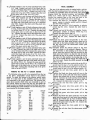
12 (nhe silicon rectifier diodes supplied
with the kit may be any of the three
types shown in the illustration;
UJ
Cl
UJ
although different in appearance,
O~Cl
they are electrically equivalent. Con- .~~~.
U
<t
nect the cathode (or plus) lead of
one of the rectifier diodes to lug ~
#2 of terminal strip TS-l. Connect
"
the other lead of the diode to lug
#4 of terminal strip TS-1 (S-2).
IMPORTANT: Arrange the diode leads exactly as
shown in the pictorial diagram. When soldering,
hold pliers on the lead between the diode body and
the solder connection to avoid application of excessive heat to the diode.
13(""""Connect the cathode (or plus) lead of the second
diode to lug #2 of terminal strip TS-l. Connect the
other lead to lug #5 of terminal strip TS-l (S-2).
14 ( """-Connect one end of a 7" red wire to lug # 2 of the
terminal strip TS-1 (S-3). Use caution to avoid
excessive heating of the diodes. Connect the other
end to lug #3 (semi-circle symbol) of the foursection filter capacitor.
15
Connect one lead of the 50 ohm, 5 watt resistor to
lug #3 (semi-circle symbol) of the four-section filter
capacitor (S-2). Connect the other lead to lug #4
(square symbol) of the same capacitor.
~
23 ( 0 Connect one end of a 61!z" black wire to mounting
lug D of the two-section filter capacitor (S-2). Connect the other end to eyelet #4 on the PC-ll circuit board (S).
24( v(Connect one end of a 2Y2" red wire to eyelet #5
on the rear PC-lO circuit board (S-2). Note one
wire is already connected; reheat the eyelet and
insert the second wire. Connect the other end to
eyelet #5 on the front PC-lO circuit board (S).
25 ( V"'Connect one end of a 4 1h" black wire to mounting
lug C of the four-section filter capacitor. Connect
the other end to eyelet #6 of the rear PC-lO circuit board (S).
26( W"'Connect one end of a 6 1/ 2 " black wire to mounting
lug C of the four-section filter capacitor (S-2). Connect the other end to eyelet #6 on the front PC-lO
eircuit board (8).
27 ( ~onnect one end of a 11;4" red wire to pin # 3 of
V-7 (8). Connect the other end to pin #3 of V-8.
28(,0Connect one end of a 21!z" red wire to pin #3 of
V-8 (8-2). Connect the other end to pin #3 of V-6.
29 (UCo~p.ect .one end of a 1 114" red wire to pin # 3 of
V-6 (S-2). Co~.he other encLt.9-Pin..#3 of-V-5,30 (VConnect one end 'of a 7." red wire to pin # 3 of V-5
(8-2). Connect the other .fmd to lug #2 (no symbbl)
of the four-section filter capacitor.
31 (~Connect one end of a 11;4" green wire to pin # 2 of
V-7 of the front PC-lO (S). Connect the other end
eyelet #9 (S).
32(~Connect one e~d of a 1Yt" green wire to pin #2
of V-8 of the front PC-lO (S). Connect the other
end to eyelet #8 (S).
33 ( ~Connect one end of a 1 Yt" green wire to pin # 2 of
V-5 of the rear PC-lO (S). Connect the other end
to eyelet #9 (S).
34( ~onnect one end of a 1 J14" green wire to pin #2 of
V-6 of the rear PC-lO (S). Connect the other end
to eyelet #8 (S).
35 (
Connect one end of a 1 Y2" green wire to pin # 9 of
V-8 of the front PC-lO (S-2). Connect the other end
to eyelet # 11 (S).
36 ( ....,..-connect one end of a Ph" green wire to pin # 9 of
V-6 of the rear PC-lO (S-2). Connect the other end
to eyelet # 11 (S).
37( 1>'Connect one end of a 41!z" green wire to eyelet #2
of front PC-10 (S). Connect the other end to eyelet
#10 (S).
38( ~onnect one end of a 4Yz" green wire to eyelet #2
of rear PC-lO (S). Connect the other end to eyelet
#10 (S).
39 (A'"Twist together a pair of black and green wires, each
3" long. Connect one end of the black wire to eyelet
#3 on the rear PC-10 (S). Connect the same-end
of the green wire to eyelet #4 on the rear PC-10
(8). Connect the other end of the black wire to pin
#5 of V-5. Connect the remaining end of the green
wire to pin #4 of V-5.
40 (V!.wist together a pair of black and green wires, each
2%" long. Connect one end of the black wire to pin
#5 of V-5 (S-2). Connect the same-end of the green
wire to pin #4 of V-5 (S-2). Connect the other end
of the black wire to pin # 5 of V -6, and the other
end of the green wire to pin #4 of V-G.
JP.
V)
~6( v1"'Connect one
lead of a 2200 ohm (red-red-red) 1
watt resistor to lug #4 (square symbol) of the foursection filter capacitor (S-4). Connect the othef..lead
to lug #1 (triangle symbol) of the same capacitor.
17 (Vf Connect one lead of the other 2200 ohm (red-redred) 1 watt resistor to lug #1 (triangle symbol) of
the four-section filter capacitor (S-2). Connect the
other lead to lug #2 (semi-circle symbol) of the
two-section filter capacitor.
~~onnect one
end of a 61!z" red wire to lug #2
(semi-circle symbol) of the two-section filter capacitor. Connect the other end to eyelet #5 of the rear
PC-lO circuit board (S).
19( ~Connect one lead of a 22,000 ohm (red-red-orange)
Ih watt resistor to lug #2 (semi-circle symbol) of
the two-section filter capacitor (S-3). Connect the
other lead to lug # 1 (triangle symbol) of the same
capacitor.
20( \1"'Connect one end of a 61!z" red wire to lug #1
(triangle symbol) of the two-section filter capacitor
(S-2). Connect the ~ther end to eyelet #12 on the
PC-l1 circuit board (S).
21 (0'Connect one lead of the 95 ohm, 5 watt resistor to
mounting lug B of the four-section filter capacitor.
Connect the other lead to lug #2 (no symbol) of
the same capacitor.
22 ( "'fConnect one end of a 2" black wire to mOlmting
lug B of the four-section filter capacitor (S-2). tonnect the other end to mounting lug D of the twosection filter capacitor.
-====
'1""
13
--
--
- - - - - - - - - - - - - - -----
41
(vf Twist together a pair of green and black wires, each
2%" long. Connect one end of the black wire to
lug #1 of terminal strip T8-2; connect the other end
to pin #5 of V-6 (8-2). Connect one end of the
green wire to lug #2 of T8-2'. Connect the other end
Jof the green wire to pin #4 of V-6 (8-2).
42 ( ~ Twist together a pair of green and bla<;k wires, each
10%" long. Connect one end of the black-wire to
eyelet #9 on PC-11 (8). Connect the same end of
the green wire to eyelet #10 on PC-ll (8). Connect
the other end of the black wire to lug # 1 of tenninal
strip T8-2. Connect the other end of the green wire
j to lug #2 of T8-2.
43 (.,J) Twist together a pair of black and green wires, each
3" long. Connect one end of the black wire to eyelet
#3 on the front PC-lO (8). Connect the same end
of the green wire to eyelet #4 on the front PC-lO
(8). Connect the other end of the black wire to pin
# 5 of V-7. Connect the other end of the green wire
j!! pin #4 of V-7.
44 ( V!wist together a pair of black and green wires, each
2%" long. Connect one end of the black wire to pin
# 5 of V-7 (8-2). Connect the same end of the green
wire to pin #4 of V-7 (8-2). Connect the other end
of the black wire to pin # 5 of V-8, and the other
end of the green wire to pin # 4 of V-8.
45(Vf'Twist together a pair of green and black wires, each
3" long. Connect one end of the black wire to lug
#4 of tenninal strip T8-2. Connect the same end of
the green wire to lug #5 of T8-2. Connect the other
end of the black wire to pin #5 of V-8 (8-2). Connect the remaining end of the green wire to pin #4
/!.f V-8 (8-2).
46 (1'> Twist together a pair of green and black wires each
12" long. Connect one end of the black wire to eyelet #15 on PC-11 (8). Connect the same end of the
green wire to eyelet # 13 on PC-11 (8). Connect the
other end of the black wire to lug #4 of tenninal
strip T8-2. Connect the remaining end of the green
wire to lug # 5 of T8-2.
The following wires are all to be connected from the top
of the PC-11 preamplifier circuit board to the selector
switch. To make the wiring to the selector switch easier
when it is done later in the assembly process, the wires
are connected to the circuit board now. The pictorial diagram shows exactly which wires are connected to each of
the eyelets. Insert the wires from the top, and solder the
wires in place by heating the eyelets from below the board,
while checkin~ the eyelet numbers to be sure that they have
been inserted in the proper eyelets.
\
5(a
4(0
6(
7(~
8('
9( ~
10(~
H(
12( )
14
LENGTH
COLOR
EYELET
1%"
2"
2%"
1%"
4"
5H
1%"
4"
51,4"
1%"
2%"
2"
red
red
red
red
red
black
green
green
black
green
green
green
#16
#17
#14
#19
#20
#5.
#2
#3
#1
#8
#11
#7'
I
The top of the selector switch is marked with a red dot.
With the shaft pointing toward you, and the dot at the top,
a locating lug protrudes from the left front. The pictori
diagram shows the tenninal numbers, and identifies th
wafers as A (front) and B (rear). Whenever a terminal
location has separate lugs on the front and back of the
wafer, be sure you solder each wire to both lugs.
1 ( n Connect one lead of a 1.5 megohm (brown-greengreen) resistor to selector switch lug B-2. Connect
the other lead to lug B-5.
.
2 (Y5 Connect one lead of a 3.3 nf capacitor to selector
switch lug B-5 (8-2). Connect the other lead to
lug B-2.
3 (VConnec1 one lead of the' other 1.5 megohm (browngreen-green) resistor to selector switch lug A-2.
"connect the other lead to lug A-5.
4 (v'f Connect one lead of a. 3.3 nf capacitor to selector
switch lug A-5 (8-2). Connect the other lead to
lug A-2.
5("-'r"Attach the front panel sub-assembly to the main
chassis with four sheet metal screws, using two on
each side in the holes provided. Note that all but
the two wires from the stereo-mono switch pass
under the chassis.
6 (\If Carefully install the selector switch on the front
panel as shown in the pictorial diagram. Place a
%" lockwasher on the bushing at the front of the
switch, insert the switch in the hole providf'd on the
front panel and rotate it so that the red dot which
indicates the top of the switch is toward the top of
the panel. In this position the locating lug on the
front of the switch should engage the small hole in
the front panel. Fasten the switch securely in plac
with a %" nut.
7( ~Connect the red wire from eyelet #16 on the pc-n
circuit board to lug A-7 on the selector switch (8).
B( i fConnect the red wire from eyelet #17 on the PC-11
circuit board to lug A-9 on the selector switch (8).
9 ( lI"I Connect the red wire 'from eyelet # 19 to lug
>-J;.
WIRING TO THE PC-11 CIRCUIT BOARD
1( Vl
2('£{
3(
FINAL ASSEMBLY
(8).
lOvP0sition the black wire from eyelet #5 over to the
red wire from eyelet # 20 and twist them together.
Position the twisted pair in front of selector switch
wafer A (between the wafer and the front flange of
the main chassis). Connect the red wire to lug A-4
(8). Connect the black wire to lug A-3 (8).
11 (~onnect the red wire from eyelet #14 to lug
'
A-2 (8-3).
12 C0 Connect the green wire from eyelet # 8 to lug
B-7 (8).
13 ( lIIf Connect the green wire from eyelet # 7 to lug
B-9 (8).
14( ~ Connect the green wire from eyelet #2 to lug?
fi-6 (8).
15 ( "'1' Position the black wire from eyelet # lover to the
green wire from eyelet #3 and twist them together.
Position the twisted pair in front of selector switch
wafer B (between wafers B and A, but close to B).
Connect the green wire to lug B-4 (8). Connect the
black wire to B-3 (8).
16 C,j) Connect the green wire from eyelet # 11 to lu
B-2 (8-3).
17 (\l'.Connect the red wire from the stereo-mono switch •
to lug A-l.
-
18(y(Connect the green wire from the stereo-mono switch
to lug B-lo
19 ( ~ Connect the black wire of the red-and-black twisted
pair from the balance control to eyelet #6 on the
,'.
front PC-10 (8-2). This is the second wire con.
nected to this eyelet. Connect the red wire of this
pair to eyelet #7 (8).
20 ( ~ Connect the black wire of the green-and-black
twisted pair from the balance control to eyelet #6
on the rear PC-10 (8-2). This is the second wire
. connected to this eyelet. Connect the green wire of
.)his pair to eyelet #7 (8).
21 ( ""'Feed the twisted pair of green wires from the pilot
light socket through the cable clamp. Connect one
of these wires to lug #4 of terminal strip -'1'8-2.
...£onnect the other green wire to lug #5 of TS-2.
22 ( "1'" Place the main chassis upside down so that the front
panel faces you. Bring the rear panel sub-assembly
close to the proper position (also upside down), but
do not fasten in place at this time. Position the flat
four conductor cables and the twisted three sets of
wires from the input sockets on the top side of the
chassis. All the other wires will be connected on the
. ~tom of the chassis.
23 (~~nnect the black wire from the ground lugs
between input sockets # 15 and # 16 to mounting
lug A of the four-section filter capacitor (8-2).
24 (Y1'"Connect the black wire from the ground lug on the
output terminal strip mounting screw to lug #3 of
terminal strip T8-l (8).
25( "'~onnect one of the black power transformer (PAy 774) leads to lug #1 of AC outlet B (8-2). Connect
the other black power transformer lead to lug A on
the fuse holder (8).
a
tt
NOTE: If u.inl< the 120/240 volt power transformer, PB-028. replace
this steP with the steps specified on Page 16.
26(AConnect the longer black wire of the pair from the
power switch to lug # 1 of AC outlet A. Connect the
other black wire of this pair to lug #2 of AC outlet
B (8-2). Position these twisted wires under the
;;able clamp.
27 ( \-("Cut the black, orange and yellow leads from the output transformer Z-565 nearest to the rear of the
chassis to 3/1 each. Twist these together and connect
the black lead to output lug #8. Connect the orange
lead td lug #2 (8). Connect the yellow lead to
Jug #1.
r1
~
28 ( 'ItI'f Connect one end of a 7 112/1 green wire to output strip
lug # 1 (8·2). Connect the other end of this wire
/to eyelet #1 on the rear PC-lO (8).
29 (./) Twist together the black, orange and yellow leads
from the output transformer nearest to the front of
the chassis. Place these leads under the cable clamp.
Connect the black lead to output strip lug #8 (8-3).
Connect the orange lead to lug #6 (8). Connect the
. yellow lead to lug # 5.
30("A'"Connect one end of a 9" red wire to output strip
lug #5 (8-2). Connect the other end of this wire to
eyelet # 1 on the front PC-10 (8).
31 ( it Connect the black wire from lug #2 of the right
-hum control to lug #2 (no symbol) of the foursection filter capacitor (8·3). Place this wire against
. ~he rear panel.
32( 11 Connect one of the green wires from the left hum
control to lug #1 of terminal strip T8-2 (8-4).
Connect the other green wire to lug #2 of T8-2
(8-4). Position these wires under the cable clamp.
33
V control
Connect one of the green wires from the right hum
to lug #4 of terminal strip T8-2 (8-5).
Connect the other green wire to lug #5 of T8-2
(8·5). Position these wires under the cable clamp.
Now tighten the hardware holding the cable clamp.
34(.,t Attach the rear panel sub-assembly to the main
chassis with four sheet-metal screws, using two on
each side in the holes provided.
35 (~Pass the line cord through the rubber grommet
mounted in the rear panel, and push it through far
enough to tie a knot 4" from the end. Tie the knot.
Then, separate the two conductors of the line cord
for 2". Cut 'h" from one of them, and strip and tin
~ ends of both.
36 (VConnect the shorter of the two line cord conductors
to lug #2 of AC outlet A (8-2). Connect the longer
conductor to lug #1 of AC outlet A (8-2). Now
tum the chassis over.
37(vjTwist together the two red wires from input sockets
#9 and #10 and the black wire from the short lugs
between them. Connect the red wire with the previously bent end to eyelet #18 on the PC-ll circuit board (8). (Note the correct wire position
shown on the pictorial diagram.) Twist another tum
of the black wire around the remaining red wire and
connect the black wire to eyelet #5 on the PC-ll
circuit board (8-2). This is the second wire connected to this eyelet. Connect the remaining red
wire to lug A-8 of the selector switch (8). Position
these wires from the rear panel against the main
chassis.
38(~ist together the two gr~en-·Wires from input
sockets #1 and #2 and the black wire from the
short lugs betweeft them. Connect the green wire
with the preyiously bent end to eyelet #6 on the
PC-ll circuit board (8). (Note the correct wire
position shown on the pictorial diagram.) Twist
another tum of the black wi,re on the remaining
green wire and connect the black wire to eyelet # 1
on the PC-ll circuit board (8-2). This is the second
wire connected to this eyelet. Connect the remaining green wire to lug B-8 of the selector switch (8).
Position these wires from the rear panel against the
main chassis.
39 (
Connect the yellow wire from input socket # 16 on
)he rear panel to lug A-I of the selector switch (8-2).
40( D( Connect the orange wire from input socket #15 to
/Iug A-12 (8).
41(""') Connect the red wire from input socket #14 to lug
A-ll (8).
42~Connect the brown wire from input socket #13 to
lug A-lO (8).
43 (v{Connect the yeUow wire from input socket # 8 to
lug B-1 (8-2).
44(JConnect the orange wire from input socket #7 to
lug B-12 (8).
45( VConnect the red wire from input socket #6 to lug
B-ll (8).
46
Connect the brown wire from input socket # 5 to
lug B-lO (8).
eI
(J
This completes the wiring of the..-ubit. DO NOT PLUG IN
THE AC CORD UNTIL THE TUBES HAVE BEEN INSTALLED AND
THE COVER AND BO'ITOM PLATE ARE SECURELY IN PLACE.
15
PLACES TO DOUBLE-CHECK AFTER WIRING
Be sure that all mounting screws and nuts are tight.
Compare the wiring of each of the tube sockets to that
shown in the pictorial diagram. All connections should be
securely soldered, with enough space between connections
to the tube socket connecting lugs so that there is no chance
of an accidental short-circuit.
Compare the wiring to each lug of the filter capacitors
to that shown in the pictorial diagram. Check carefully to
see that all connections have been soldered, and that excess
lead length has not caused any connection to short-circuit
to the chassis.
Examine all connections with particular care, to be sure
that none of them have solder blobs which project enough
to touch the bottom plate when it is installed. Check the
terminal strips and the filter capacitors in particular.
Check each lug on each of the controls on the front
panel, to be sure that all of them have been soldered.
Check the twisted wires at the ends where they have been
soldered to see that the insulation has not melted to cause
a shorted condition. This will occur if too much heat has
been applied when soldering these wires and they have been
twisted too tightly. Pay particular attention to the leads
going to pins #4 and #5 of tube sockets V-5, V-6, V-7 and
V-B, and to lugs #1, #2, #4 and #5 of terminal strip
T8-2.
The wires to the selector switch should be positioned as
shown below. Note particularly the twisted pairs to lugs A3
and A4, and to lugs B3 and B4. These should be close to
the front surface of each wafer.
The bottom plate and the cover are attached at the same
time, by setting the amplifier chassis on the bottom plate,
which fits outside the main chassis, and then lowering the
cover onto the chassis. The chassis, bottom plate and cove
are fastened together by four sheet metal screws throu
the sides of the cover. This should be done before the fron
panel is installed.
Install the pilot light jewel by inserting it from the front of the panel,
gripping the jewel spring with pliers
to squeeze it open, and sliding the
spring over the jewel to hold it in
place. The panel should then be placed
over the control shafts, and %" nuts
placed on the control shaft bushings to
hold the panel in place. Use care in
attaching the nuts to avoid scratching
the finish of the panel. The cover can afterward be removed,
if necessary, without removing the front panel.
All the knobs of the 8CA-35 use small set screws to
secure them to the shafts. A small tip screwdriver is
required. The two large knobs go on the selector switch
shaft and the volume control shaft. The selector switch
shaft has a flatted portion, and the set screw in the knob
should be tightened against the flat. Then when the knob
is rotated fully counter-clockwise, the index mark on the
knob should point to "Tape head".
The balance control and volume control knobs should be
set so that the full counter-clockwise point corresponds to
7 o'clock on a clock face, and then full clockwise rotation
will correspond to 5 o'clock. This makes the index on the
balance control point to 12 o'clock for nominally balanced
operation. However, either of these knobs can be installed
offset if desired so that the 12 o'clock position represents
average volume and balance in your individual system.
The bass control knob should be set so that full counter
clockwise is at 6 o'clock, and the treble control knob set so
that full clockwise is at 6 o'clock. The 12 o'clock position
will then be the electrically "flat" setting for each.
SPECIAL INSTRUCTIONS FOR OPTIONAL
120-240 VOLT POWER TRANSFORMERS
BLACK
I
Tum the chassis upside down, and shake it vigorously to
dislodge any wire clippings or bits of sol~er.
.
The tubes and the fuse should now be mstalled.; the pICtorial diagram shows the location of each tube. IMPORTANT: When inserting the tubes in their sockets for the
first time, the socket should be supported from below the
chassis to avoid strain on the circuit board because of the
tight fit of new sockets. V-I and V-2 are 12AX7;ECC-83
tubes and are installed in PC-ll. V-3 and V-4 are 7199
tubes; one of each is installed on each PC-10 in the socket
closest to the PC-ll board. V-5, V-6, V-7 and V-8 are
6BQ5;EL-84/7189 tubes, and they go in the remaining
PC-10 sockets. Insert the pilot lamp in its socket.
The four rubber feet should be installed in the corner
holes of the bottom plate. To mount each foot, insert a #6
machine screw in the recessed end of the foot, and secure
it with a #6 nut on the inside of the bottom plate.
16
VIOLET
aWHITE
BLACK
aWHilE
BLACK
•
.
,
t
VIOLET
120·Yol'
VIOLET
a WHITE
BLACK
aWHITE
.
VIOLET
240·yolt
Dynakit 8CA-35 amplifiers supplied with optional power
transformer PB-028 can be wired for use with either 120
or 240 volt, 50 or 60 cycle, AC power sources, as follows:
For
r 20
1(
) Connect the black lead from the power transformer
Volt Operation
to lug #1 of AC outlet B.
2 ( ) Connect the black-and-white lead from the power
transformer to lug # 1 of AC outlet B (8-3).
3 ( ) Connect the violet lead to lug A on the fuse hoide
4( ) Connect the violet-and-white lead to lug A on the
fuse holder (8-2).
for 240 Volt Operation
1 ( ) Connect the violet-and-white lead to lug # 1 of terminal strip TS-l.
) Connect the black-and-white lead to lug #1 of terminal strip TS-1 (S-2).
3 ( ) Connect the black lead to lug # 1 of AC outlet
B (S-2).
4 ( ) Connect the violet lead to lug A on the fuse
. holder (8).
When using the 240 volt connection, a one ampere sloblo fuse should be used instead of the two ampere fuse
recommended for the 120 volt connection.
IN CASE OF TROUBLE
Although your SCA-35 should function properly after
assembly, sometimes an error of wiring or a defective component may require trouble shooting. The location of a
difficulty can be determined most efficiently if a systematic approach is used. This is based on understanding
the inter-relationship between the different sections of the
circuit, and reference to the section which describes the
circuit will be helpful in achieving this understanding. The
suggestions for servicing which follow are based on trying
to localize the circuit section which is at fault.
Naturally, you should check and double check your wiring as a first step in trouble shooting. It is good to have
somebody else check it through for you, as he may see an
error which you overlook consistently. This checking can
be done with the pictorial diagrams or with the step-bystep instructions. If you use both, you will have a double
check on the accuracy of wiring. Look not only to see if all
ires and components go to the correct points, but also to
see that all solder connections are good and that no wires
or parts touch spots where they should not. Sometimes a
bit of solder will run from one point to another where no
connection is desired. Sometimes a lead is left too long
and hangs out, touching another point. All connections
should be examined with this in mind.
Another source of trouble is that wires are twisted so
tightly together that they break through the insulation and
cause short circuits - or the wire itself may be broken
within the insulation if twisted too tightly.
One general test should be made before serious trouble
shooting begins. This is to determine whether the fault is
in the SCA-35 or in associated equipment. Sometimes, connections to the loudspeakers are at fault, or it may be that
the pickup cartridge is not connected properly in the player.
Pilot Light and/or Tubes Do Not light
If after plugging the SCA-35 into an AC outlet and
turning the power switch on, the pilot light does not go on,
see whether there is a normal glow in the center of the
tubes. If the tubes glow while the pilot light does not light,
then the fault is in the pilot light itself - and the bulb
should be replaced - or in the wiring to the pilot light
socket. This wiring should be traced to see whether the
connections are correct and soldering makes good contact.
If some of the tubes light, but others do not, then the heater
wiring to the unlighted tubes should be traced. There are
two sets of heater wires, a set for each channel, one of
~hich is brown and brown-white, the other green and green\....hite. These should be traced from the PA-774 transformer
to TS-2 to see if the wiring compares with the pictorial
diagram.
If all the tubes in one channel light, but none in the other
channel, interchange the brown with green wires and
brown-white with green-white temporarily to determine
whether one of these sets of windings is defective. For
example, if the interchange should make tubes light which
were formerly not lighted, then there is nothing wrong
with the wiring to the tubes, hut most probably there is
something wrong with the wiring from the transformer
(which should be returned to DYNA Company for replacement in this case). This principle of substitution is helpful
for locating the source of trouble.
If neither tubes nor pilot lamp light, then the first thing
to check is the fuse. If this is blown, another of the same
rating should be used, 2 ampere (except 1 ampere for 240
volt models). If the second fuse blows, then it is essential
to determine the reason for this instead of continuing to
replace fuses. Under no circumstances should. a fuse of
higher rating be used.
Siown fuses
The fuse will blow if there is a short circuit in the equipment. If an ohmmeter is available, resistance measurements
should be made at the two and four-section electrolytic
capacitor terminals. Unplug the power cord and discharge
each section of the capacitor to ground before making any
of these measurements. The resistance to ground should be
over 50,000 ohms on all sections except the blank terminal
of the four-section capacitor where it should be about 95
ohms. Any lesser resistance values indicate either capacitor
failure or a path to chassis which should not exist. Disconnect wires to each capacitor section to isolate the capacitor.
All sections should read high resistance once wires are
disconnected - if not, the capacitor is at fault.
If one of the silicon diodes is defective, or if it has been
installed backwards, the four-section capacitor will probably have been permanently damaged. In similar fashion,
if the four-section capacitor is defective, it may cause the
failure of the silicon diodes. Therefore, if either capacitor or
diodes are found to be at fault, both should be replaced.
Blown fuses can also indicate a defective PA-774 transformer (though this is a rare possibility). To check for
this, disconnect all leads of the PA-774 except the two
black primary leads; and with these leads in position where
they touch neither each other nor other components, plug
in the unit and turn it on. If the fuse blows under this condition, the trouble is definitely in the PA-774. If the·PA-774
is proven satisfactory in this test, test the diodes and
capacitors by disconnecting all wires to the capacitors
except the wire from lug #2 on TS-l to lug #3 of the
four-section filter capacitor t leaving the resistors on the
capacitor terminals. If plugging in the unit and turning it
on then does not blow a fuse, these components are exonerated, and it is necessary to seek a short circuit elsewhere
in the circuit.
The output tubes can be tested as the source of blown
fuses by removing all the 6BQ5's simultaneously from their
sockets. If this cures fuse blowing, then one of them is
probably bad. The unit should never be operated with only
one, two or three of these four tubes inserted or damage to
the remaining tubes is probable. Heater glow at the top and
bottom of each tube is normal, but if the plate (the large
black metal part) of the output tubes glows red it indicates
a probable short in the tube or at pin #3 of any of the output tube sockets, or a short to the chassis of some part of
the heater wiring.
17
Both Channels Not Working
Should neither channel function, there is the possibility
that a similar mistake has been made in the wiring to both
sides. This is an unlikely situation, but it should be checked
by visual comparison of the wiring with the diagrams.
Generally, the cause of malfunction of both channels
together lies in the one section of the unit which is common to both channels - the power supply. The checking of
this section is covered earlier.
It is also possible that the unit is working on radio or
other high level input, but not on phono or tapehead. If
this is true for both channels together, then the power
supply wiring which connects to the PC-ll board should be
checked, as this is the only element common to both channels in the preamplifier section.
One Channel Not Working
If tubes in one channel do not light, the heater circuits
must be checked as described above. Tubes can be interchanged between the two sides to see if substitution shows
up a faulty tube. If this cures the bad channel, then evidently the faulty tube has been located.
If it is not a tube which causes the trouble, then it is
necessary to determine whether it is in the preamp section
(the PC-ll) or the amplifier section (the PC-lO). If radio
input is satisfactory while phono is not, then the trouble
is in the PC-ll section which handles phono and tapehead
inputs, or in the wiring associated with the selector switch.
If no inputs function, then the difficulty is either in the
front panel wiring which includes the tone control sections,
or in the PC-lO section or in the Z-565 output transformer which connects to that channel. The wiring of the
front panel must be carefully compared on both left and right
channels. It is possible to re-do the wiring and to interchange the two PC-lO boards to determine whether the
fault is on one of these. It is also possible to interchange
the Z-565 output transformers to try to isolate the trouble.
However, a fault in the output transformer is most unlikely,
and this should be tried as a last resort.
If both channels work on radio or other high level input,
but only one works on phono or tapehead input, then the
trouble is in either the PC-ll board or in the selector
switch or in the front panel wiring from selector switch
through the front panel controls. The PC-ll board has both
preamplifier sections in a parallel arrangement, so comparison visually of wiring and parts should indicate whether
there is any difference between these sections.
Each section of the selector switch should be identical in
appearance and in wiring. These should be compared carefully. The 12AX7's on the PC-ll should be interchanged to
see if one is at fault.
Hum and Noise
If the unit is working, but there is excessive hum or
noise, the first step is to see whether the trouble is in the
SCA-35 or associated equipment. The SCA-35 should be
checked alone, with all other equipment except the speakers
disconnected, and with the cover and bottom plate on the
SCA secured in place. If the hum is reduced without the
other equipment, then it will be necessary to determine
what kind of ground connections are necessary between
equipment to reduce the hum. Sometimes connecting wires
from chassis to chassis are good, sometimes they are harmful. Reversing line plugs on associated equipment may be
helpful. It must be understood that hum which disappears
when associated equipment is disconnected or turned off,
is not a problem of the SCA-35.
18
Hum which persists after other equipment is eliminated
as a source of trouble is generally a result of either faulty
wiring or a faulty tube. Wires which are not positioned as
shown in the diagrams, may be a cause of hum. This .
particularly true for the wires which lead from the PA-7
transformer, since these wires carry AC currents which
may be a source of hum.
If a tube causes the problem, then it is not likely to
appear in both channels simultaneously. If the hum is loud
with the volume control turned .down, then it is most likely
to be associated with the 7199 tube. If it occurs on phono
or tapehead inputs with the volume turned up a bit, then
it is most likely to be associated with the 12AX7 tube for
the channel which shows the hum. These tubes can be
checked by substituting in the other channel.
An objectionable level of hiss is most likely caused by a
defective resistor on a printed circuit board. If it is heard
with the volume turned down, it is likely to be part of the
7199 circuit - it can often be located by wiggling the body
of the resistor (using insu]ated pliers) to see if the hiss is
affected. If it is on phono or tapehead input, with volume
turned up, then the same possibility applies to the 12AX7
circuit.
Some hum and hiss will always exist - depending on
speaker efficiency and other factors. However, it should be
negligible at normal listening levels. At very high levels,
some noise will always be audible, but of course this will be
masked by the loud sound. With the volume control at
minimum, noise with a shorted input should be less than 2
millivolts across the 16 ohm output; with volume at maximum, it should not exceed 40 millivolts at this point.
Sometimes, the magnetic field around the PA-774 transformer may cause some vibration of the cover which is
audible as a buzzing sound. This can be e]iminated by
placing a' small wedge of fibreboard or wood on top of th
transformer, between it and the cover.
Distorflon
If distortion is encountered, the first thing to do is to
make sure that all inputs and outputs are properly connected and properly functioning. If the leads to a loudspeaker have frayed cables and touch several screws simultaneously, this can be a source of distortion. If a ceramic
cartridge is inserted into the magnetic cartridge input (or
if a tape amp goes in the tapehead input) there will be
overloading of the input and severe distortion.
If the trouble seems to be in the SCA-35, then determine
if it is in one channel or both. If in both channels, the only
circuitry common to both channels is that of the power
supply and the 95 ohm resistor in the cathode circuits of
the 6BQ5 tubes.
If only one channel has distortion, tests similar to those
described previously should be used to localize the problem and tubes should be interchanged to see if they are a
cause of it. Inspection of parts on the printed circuit boards
should be made to see if both sides of the circuit are
identical.
Voltage Measurements
The voltage chart shown with the schematic diagram will
be of considerable aid in troubleshooting if there is a
vacuum tube voltmeter or similar test instrument available.
Voltages through the circuit should be compared carefully
with this chart. Deviations up to 20% are not signs 0
abnormality, but past this range they indicate a malfunc
tioning of the circuit at that point. Such measurements can
help to locate defective parts, miswiring, or bad tubes.
-
_i
R 1
R 2
R 3
R 7
R 8
R 9
R 10
R 11
R 12
R 13
R14
R15
R16
R17
1.2 megohms
150,000 ohms 1 watt 5%
5,600 ohms 5%
120 ohms 1 watt 5%
120 ohms 1 watt 5%
1.2 megohms
47,000 ohms
390 ohms
18,000 ohms 5%
100,000 ohms 5%
47,000 ohms
1.5 megohms
1.2 megohms
150,000 ohms 1 watt 5%
5,600 ohms 5%
120 ohms 1 watt 5%
120 ohms 1 watt 5%
R 18
R19
R20
R21
R22
R 23
R24
R25
R26
R27
R 28
R29
R30
R 31
R32
R33
R34
All resistors are Y2 watt, 10% unless otherwise noted.
1.2 megohms
R 35 470.000 ohms
C 9 330 pf mica 5%
47,000 ohms
R 36 470,000 ohms
C 10 3.3 nf 10%
390 ohms
R 37 82,000 ohms 5%
C 11 10 nf 10%
18,000 ohms 5%
R 38 22.000 ohms
C 12 10 nf 10%
100,000 ohms 5%
R 39 2200 ohms 1 watt
C 13 3.3 nf 10%
4~000 ohms
R 40 2200 ohms 1 watt
C 14 3.3 nf 10%
1.:> megohms
R 41 50 ohms 5 watts
C lS 22 nf 10%
10,000 ohms
R 42 95 ohms 5 watts 5~
C 16 22 nf 10%
10,000 ohms
..
C17 .lmfdI16V.
C 1 .1. mfd @ 16 v.
C 18 1 mfd
250v.
18,000 ohms
C 2 22 nf @ 400v.
C 19 .1 mfd 400 v.
18,000 ohms
C 3 .1 mfd @4oov.
C 20
1 mfd
400 v
4.7 megohms
C 4 330 pf mica 5%
C 21 i2 pf @ 600 v. 5%
270.000 ohms 1 watt 5%
c 5 3.3 nf 10%
C 22 .02 mfd @ 500 v.
560 ohms 5%
C 6 .1 mfd @ 16 v.
C 23 50/50 mfcl @ 450 v.
22,000 ohms 1 watt 5%
120,000 ohms 5%
C 7 22nf@400v.
C2460/40/[email protected]
C 8 .1 mfd @ 400 v.
100 @ 25 v.
27,000 ohms 1 watt 5%
_ _---()
SPARE~
FROM TAPE AMPfoT------<>AII
volume
balance
bass co
treble c
hum co
V 1 1
V 2 1
V
V
V
V
3
4
5
6
•
V 7
V 8
PIN
I
2
3
via V2
(12AX7)
180
-.2
.5
V3aV4
( 7199)
255
55
32
V-5-6-7-8
(68Q5)
RAOIOCo}------<>
TS-I LUG
HI LEVELlQ1'---+,
0"
0
0
380
C23 LUG
320 250
6.3
AC
r----l
6.3
A
315
315
-
14
350
... •
I
r----l
.to
370
5
6d
0
... •
380
LEVEL(~--+J~
4
16
C24 LUG
~
e
D 2
VOLTAGE CHART
TO TAPE RECORO(~----~!-o'-"';";_
LO
o
tlNtlSED PINS MAY HAVE INTERNAL CONNEI
SOME TtlBES (DEPENDING ON BRAND), MAYI
PEAR AT THESE POINTS.
WITH V. Tv. M.
VOLTAGES MEASUREf)
FROM TAPE HOll»---.I-<lU
ST~"EOI
"0"0
Ri5 7
CII
0:
:1
"V
TO TAPE RECORD(Ot~-----r1""'-""-""'--:
CI2
FROM TAPE AMP(~-----() III
RAOIO(~---o
110
~~
'r/
or
~
SPAREl~----o112
CI3
tr~Ir
I
(
I
."
:II
31
1
..•
....
'
g, :••
31 '
0
:1z
gl
/
I
R271
I
'"r'
"-
""- ,,
I
I
HI LEVEL(ot'---+;
l
PHONO
::
:•
•
LO LEVELlC»--'-.IJ'--o
FROM TAPE HO(Q'~-""""-o
..
E
19
SCHEMATIC DIAGRAM
Silicon rectifier, 500 ma,
1000 PIV
2 Silicon rectifier, 500 ma,
1000 PIV
'olume control-250,OOO ohms
lalance control-750,OOO ohms
lass control-2 megohms
reble control-500,OOO ohms
lum control-l,OOO ohms
, 1 12AX7/ ECC-83
, 2 12AX7/ECC-83
, 3 7199
, 4 7199
, 5 6BQ5/ EL-84
, 6 68Q5/ EL-84
, 7 68Q5/ El-84
, 8 6BQ5/El-84
~_-.-'V..::.:[L~ 16il
)o-_+,O=.::A~
8il
c
IART
5
i.3
At
--,
U
AC
--,
;,3
At
~----'T"""'"
'----;f-8,LK
6
7
8
10~
0
.25
.7
0
70
0* 360
9
55
0· 365
315
~
TO
EYELET 12
PC-II
IL CONNECTIONS, THEREFORE
lOJ, AlAYHAVE VOLTAGES AP-
C23
V,M.
J
~
~24
C22
J20AC
BLJ:
Q:
W
111:
ce
...
......
W
en
Q:
...zv
ac
0
......
:.
.......
Q:
PA-774
:::)
....zv
~
v
".-_-t-'v",n'-f2} 16il
>--_+-,O!.!!.A~
ao
c
...
20
4
FACTORY SERVICE AND WARRANTY
The SCA-35 is designed to provide reliable, trouble-free
perfonnance for a long period of time, when properly
assembled and installed. It is intended for use with the
120-volt AC power supplied to most homes. Although variations of several volts above or below this figure will have
no pronounced effect upon performance or component life,
the nonnal guarantee on the equipment is not applicable
if it is operated with AC inputs greater than 130 volts. If
your local power is this high or higher in voltage, it is
suggested that a voltage regulating or adjusting device be
installed to protect the amplifier.
All parts used in the SCA-35 are guaranteed for a period
of one year from the date of purchase except tubes, which
carry the standard electronic industry (EIA) gO-day warranty. Defective parts will be replaced at no charge if they
are returned prepaid to the factory either directly or via
the dealer from whom the kit was purchased. After the
guarantee period has passed, DYNACO, Inc. will supply
any non-standard parts used at net prices. Parts which are
standard (resistors, capacitors, tubes) can generally be
purchased from a local electronics supply store.
n it is believed that a transfonner is defective, it should
be disconnected by unsoldering, never by cutting its leads
so short that it cannot be re-used. Warranties on the trans-
formers are void if the leads are cut too sJwrt for re-use.
Factory assembled amplifiers include a one-year warranty on labor as well as parts.
Fixed-charge service and maintenance are not available
for kits which are incompletely wired or kits wired with
solder other than rosin core type, or kits physically or
electrically modified without prior factory authorization.
The serial number on the front cover of this instruction
book must be mentioned in all correspondence and in any
case where parts are returned, or kits sent or brought to
the factory for service.
It is the factory prerogative to limit the service facility
to one year from the date of purchase.
When shipping the amplifier to DYNACO, Inc., for
service, attach a note specifying the symptoms, the name
and address of the sender, and the serial number of the
kit. The kit should be securely packed to withstand the
abuses of handling in transit. The front plate should be
protected with a plastic or wax paper covering, or it may be
removed. The unit should be placed in a rugged carton surrounded by several inches of shredded paper or other soft
packing material. The original carton in which the amplifier is supplied is suitable for shipping if the original inserts
are properly used.
Shipment should be made by prepaid EXPRESS, where
possible; repaired kits will then be returned EXPRESS
C.O.n. for freight and service charges (unless these
charges have been prepaid). PARCEL POST IS NOT A SAFE
If the kit has been completely assembled, yet cannot be
made to function properly, or if difficulty is apparent after
a short period of use, we will service the kit for a fixed
charge of $10.00, plus the cost of the parts which are outside the warranty or have been damaged by the user.
METHOD FOR THE SHIPMENT OF ASSEMBLED KITS, AND SHOULD
NOT BE USED FOR THIS PURPOSE.
The DYNA Company assumes no liability or responsibility for damages or injuries sustained in assembly or
operation of the Dynakit.
PARTS LIST
Parts of similar type which do not change performance may sometimes be included
as a matter of expediency. This will account for slight variations in va,lue or appearance.
CDnfrols
Reslsfors
1¥""50 ohms, 5 watts, 10% - R41
~ 95 ohms, 5 watts, 5% - R42
0. 2200 ohms (red-re<!-red), 1 watt, 20% - R39, R40
IV 10,000 ohms (brown-black-orange), 'h W, 10% - R25, R26
,jl- 18,000 ohms (brown-gray-orange). '/2 W, 10% - R27, R28
J- 22,000 ohms (red·re<!-orange), lh W, 10% - R38
.%' 1.5 megohms (brown·green-green), %W, 10% - R12, R24
,y Selector switch - 134601
V Volume control-177254
J,.. Balance control - 167754
.v
Y"SPST slide switch (two lugs)
.... Fuse holder with rubber washer and circular nut
Capac/for.
or' Fuse, 2 ampere, Slo·Blo
~2
n! (.02 mid) 10% - C15, C16
'9-"10 n! (.01 mid) 10% - Cll, C12
...... 3.3 n! (.0033 mid) 10% - C5, CI0, C13, C14
oJ...-'.02 mid 500V disc - C22
YTwo-section filter capacitor, 50/50 @ 450V - C23
J...- Four·section filter capacitor, 6Oj40nO @ 450V; 100 @ 25V - C24
Hardware
#4 Machine screws
#4 Nuts
49 #4 Lockwasbers
. 4 #6 Machine screws
4 #6 Nuts
~ #6 Sheet metsl screws
12 #8 Machine screws
12 #8 Nuts
12 # 8 Lockwashers
111': %" Control mounting nuts
i(' %" Lockwashers
"f" Ground lug
k' Pilot light jewel
.. Pilot light jewel spring
'lY"Rubber grommet
l'" Cable clamp
#I' Rubber feet
Bass control - 167205
IV Treble oontrol - 167504
12"" Hum oontrol - 147102
fY DPDT slide switch (six lugs)
57
49
_.L
8" PEC tone control circuit module (7 leads) - 555002
.t'" PEC input circuit module (5 leads) - 555003
.:.Y Silicon rectifier, 500 rna 1000 PIV
~
Mounting wafers for filter capacitors
\l.o Pilot light socket
~
Pilot lamp #47
'" AC outlet
.....·4 socket input socket strip
~ 4 screw terminal strip
IY 5 lug terminal strip
.. 9 pin tube socket
~ Hookup wire (I each red, green, black)
"" Flat 4-conductor cable
~Irisulating sleeving (black)
u,... Line cord with plug
Y'Chassis assembly (5 pieces)
",",PA-774 power transformer
Q' Z-565 output transformer
,z..--PC-I0 circuit board assembly
~ PC-ll circuit board assembly
yOutput tube 6BQ5/EI.r84/7189 (matched)
Driver tube 7199
02" Preamplliler tube 12AX7jECC-83
• Large knob
'8 Small kn.ob
\l/ Front panel
-r Instruction manual with pictorial diagrams
.):- Warranty card
r
e--
21
s