1
-
OPERATORS MANUAL
MOBILE and INDUSTRIAL
GENERATORS
5.0Kw BCDR 15.0Kw BCDBR
7.6Kw B R
PUBLICATION NO. 041283
. SECOND EDITION
APRIL 2006
..
~ WESIERBEKE
WESTERBEKE CORPORATION .150 JOHN HANCOCK ROAD
MYLES STANDISH INDUSTRIAL PARK· TAUNTON MA 02780
WEBSITE: WWW.WESTERBEKE.COM
§JTAI'rMDtrber NlIIltHffll Mflrine Mfl"./lIdIIrm Assoclfltlo"
.u:_w
'A WARNING
Exhaust gasses contain Carbon Monoxide, an odorless and
colorless gas. Carbon Monoxide is poisonous and can cause
unconsciousness and death. Symptoms of Carbon Monoxide
exposure can include:
-Oizziness
- Throbbing in Temples
-Nausea
- Muscular Twitching
-Headache
- Vomiting
- Weakness and Sleepiness - Inability to Think Coherently
IF YOU OR ANYONE ELSE EXPERIENCE ANY OF THESE SYMPTOMS,
GET OUT INTO THE FRESH AIR IMMEOIATELY. If symptoms persist,
seek medical attention. Shut down the unit and do not restart
until it has been inspected and repaired.
WARNING
A WARNING DECAL is provided by
WESTERBEKE and should be fixed to a
bulkhead near your engine or generator
WESTERBEKE also recommends installing
CARBON MONOXIDE DETECTORS.
They are inexpensive and easily obtainable
at your local hardware store
'GGnerators Produce CARBON MONOXIDE
Regular Maintenance Required
rry~~.!'!~~~
CALIFORNIA
PROPOSITION 65 WARNING
Diesel and gasoline engine exhaust and
some of its constituents areknown.to the
State of California to cause cancer, birth
defects, and other reproductive harm.
SAFETY INSTRUCTIONS
INTRODUCTION
• Do not operate with the air cleaner/silencer removed.
Backfire can cause Severe injury or death.
• Do not smoke or permit flames or sparks to occur near
the fuel system. Keep the compartment and the
engine/generator clean and free of debris to minimize the
chances of fire. Wipe up all spilled fuel and engine oil.
• Be aware - diesel fuel will·bum.
Read this safety manual corefuUy. Most accidents are
caused by failure to follow fundamental rules and
precautions. Know when dongerous conditions exist and
take the necessary precautions to protect yourself, your
personne4 and your machinery.
PREVENT BURNS - EXPLOSION
PREVENT ELECTRIC SHOCK
A WARNING: Explosions from fuel vapors can cause
injury Dr death!
A WARNING: 00 not touch AC electrical connections
. while engine is running. Lethal voltage is present at
these connections!
•
Do not operate this machinery without electrical
enclosures and covers in place.
• Shut off electrical power before accessing electrical
equipment
• Use insulated mats whenever wolring on electrical
equipment
• Make sure your clothing and skin are dry. not damp
(particularly shoes) when handling electrical equipment.
• Remove wristwatch and all jewehy when working on
electrical equipment.
• Electrical shock results from handling a charged
capacitor. Discharge capacitor by shorting terminals
together.
•
•
•
•
•
•
•
PREVENT BURNS - HOT ENGINE
A WARNING: 00 not touch hot engine parts or
ACCIDENTAL STARTING
exhaust system components. A running engine gets
reryhot!
•
A WARNING: Accidental starting can cause Injury
Dr death!
Always check the engine coolant level at the coolant
recovery tank.
• To prevent accidental starting when servicing the
generator. remove the 8 amp fuse from the control panel.
• Disconnect the battery cables before servicing the engine/
generator. Remove the negative lead first and reconnect
it last
• Make certain all personnel are clear of the engine before
starting.
• Make certain all covers, guards, and hatches are
re-installed before starting the engine.
A WARNING: Steam can cause injury Dr death!
•
All fuel vapors are highly explosive. Use extreme care
when handling and storing fuels. Store fuel in a
well-ventilated area away from spark-producing
equipment and out of the reach of children.
Do not fill the fuel tank(s) while the engine is running.
Shut off the fuel service valve at the engine when servicing
the fuel system. Take care in catching any fuel that might
spill. DO NOT allow any smoking, open flames, or other
sources of fire near the fuel system or engine when
servicing. Ensure proper ventilation exists when servicing
the fuel system.
Do not alter or modify the fuel system.
Be sure all fuel supplies have a positive shutoff valve.
Be certain fuel line fittings are adequately tightened and
free ·of leaks.
Make sure a fire extinguisher is installed nearby and is
properly maintained.. Be familiar with its proper use.
Extinguishers rated ABC by the NFPA are appropriate
for all applications encountered in this environment
In case of an engine overheat, allow the engine to cool
before touching the engine or checking the coolant
PREVENT BURNS - FIRE
A WARNING: Fire can cause injury Dr death!
•
Prevent flash fires. Do not smoke or permit flames or
sparks to occur near the carburetor, fuel line, filter, fuel
pump, or other potential sources of spilled fuel or fuel
vapors. Use a suitable container to catch all fuel when
removing the fuel line, carburetor, or fuel filters.
Engines & Generators
i
SAFETY INSTRUCTIONS
BATTERY EXPLOSION
A WARNING: Carbon monoxide (CO) Is an Invisible
A WARNING: Battery explosion can cause injury
odorless gas. Inhalation produces f1u~lIke symptoms,
nausea 01 death!
01 death!
•
Do not smoke or allow an open flame near the battery
being serviced. Lead acid batteries emit hydrogen, a
highly explosive gas, which can be ignited by electrical
arcing or by lit tobacco products. Shut off all electrical
equipment in the vicinity to prevent electrical arcing
during servicing.
• Never connect the negative (-) battery cable to the
positive (+) connection terminal of the starter'solenoid.
Do not test the battery condition by shorting the terminals
together. Sparks could ignite battery gases or fuel vapors.
Ventilate any compartment containing batteries to prevent
accumulation of explosive gases. To avoid sparks, do not
disturb the battery charger connections while the battery
is being charged.
• Avoid contacting the terminals with tools, etc., to prevent
bums or sparks that could cause an explosion. Remove
wristwatch, rings, and any other jewelry before handling
the battery.
• Always tum the battery charger off before disconnecting
the battery connections. Remove the negative lead first
and reconnect it last when disconnecting the battery.
• Do not use copper tubing in diesel exhaust systems. Diesel
fumes can rapidly destroy copper tubing in exhaust
systems. Exhaust sulfur causes rapid deterioration of
copper tubing resulting in exhaust/water leakage.
• Do not install exhaust outlet where exhaust can be drawn
through vents, or air conditioners.
• Although diesel engine exhaust gases are not as toxic as
exhaust fumes from gasoline engines, carbon monoxide
gas is present in diesel exhaust fumes. Some of the
symptoms or signs of carbon monoxide inhalation or
poisoning are:
Vomiting
Muscular twitching
Intense headache
Dizziness
Throbbing in temples Weakness and sleepiness
AVOID MOVING PARTS
A WARNING: Rota,tlng parts can cause Injury
01 death!
Do not service the engine while it is running. If a
situation arises in which it is absolutely necessary to
make operating adjustments, use extreme care to avoid
touching moving parts and hot exhaust system
components.
• Do not wear loose clothing or jewelry when servicing
equipment; tie back long hair and avoid wearing loose
jackets, shirts, sleeves, rings, necklaces or bracelets that
could be caught in moving parts.
• Make sure all attaching hardware is properly tightened.
Keep protective shields and guards in their respective
places at all times.
• Do not check fluid levels or the drive belts tension while
the engine is operating.
•
BATTERY ACID
A WARNING: Sultulic acid In batteries can cause
severe Injury 01 death!
•
When servicing the battery or checking the electrolyte
level, wear rubber gloves, a rubber apron, and eye
protection. Batteries contain'sulfuric acid which is
destructive. If it comes in contact with your skin, wash it
off at once with water. Acid may splash on the skin or
into the eyes inadvertently when removing electrolyte
caps.
A WARNING:' Catbon monoxide (CO) Is a deadly gas!
HAZARDOUS NOISE
•
Ensure that the exhaust system is adequate to expel gases
discharged from the engine. Check the exhaust system
regularly for leaks and make sure the exhaust manifolds
are securely attached and no warping exists. Pay close
attention to the manifold and exhaust
• Be sure the unit and its surroundings are well ventilated.
• In addition to routine inspection of the exhaust system,
install a carbon monoxide detector. Consult your dealer
for installation of approved detectors.
A WARNING: High noise levels can cause healing
loss!
• Never operate an engine without its muffler installed.
• Do not run an engine with the air intake (silencer)
removed.
• Do not run engines for long periods with their enclosures
open.
A
WARNING: Do not wolk on machinery when you are
mentally 01 physically incapacItated by fatigue!
Engines & Generators
ii
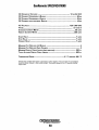
TABLE OF CONTENTS
Parts Identification ....................................................2
Introduction ................................................................3
Engine Adjustments (cont.) ......................................22
Injection Timing ................................................. 25
Warranty Procedures ............................................ 3
Remote Panel ....................................................... 3
Frequency Adjustment ....................................... 26
Fuel Run Solenoid .............................................. 26
Electronic Governor ........................................... 27
Alternator Testing/Troubleshooting ........................ .28
Battery Care ....................................................... 29
Diesel Fuel, Engine Oil and Engine Coolant.. ............ 5
Generator Control Panels .....................................:..... 6
Description of Switches ....................................... 6
Description of Gauges .......................................... 6
Remote Panel ...............................................'.....'... 6
Preparations for Initial Start-Up ................................7
Prestart Inspections .............................................. 7 ,
StartingJStopping Procedure ...................................... 8
Safety Shutdown Switches .........................................9
Generator Break-In Procedure ................................. 10
The Daily Routine .............................................. l0
Maintenance Schedule ............................................. 12
Fuel System ..............................................................13
Fuel FilterlWater Separator ................................ 13
Fuel Injection Pump ........................................... 13
Fuel Lift Pump ................................................... 13
Fuel Lift Pump Filter ......................................... 13
Fuel Filter ........................................................... 13
Engine Fuel Filter............................................... 13
Cooling System ......................................................... 14
Changing Coolant. .............................................. 14
Thermostat .......................................................... 15
Air Intake Filter/Silencer ................................... 15
DC Circuit/BaHery .....................................................30
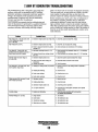
Control Panel Troubleshooting .................................31
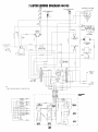
7.6 BTDR Wiring Diagram (#44743) .......................... 32
7.6 BTDR Wiring Schematic (#44743) ...................... 33
5.0 BTDR Wiring Diagram (#44742) .......................... 34
5.0 BTDR Wiring SchematiC (#44742) ...................... 35
Remote Stop/Start Panel Wiring (#44329) ...............36
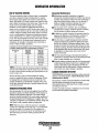
Generator Information ..............................................37
BT Generator Troubleshooting .................................38
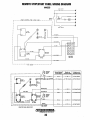
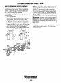
7.6KW BT Generator Single Phase ...........................39
Circuit Breaker ................................................... 39
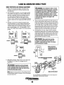
No-Load Adjustment ......................................... .40
Residual Voltage Check .................................... .41
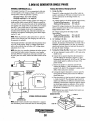
Bridge Rectifier ..................................................42
Exciter RotorlField .............................................43
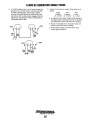
Measuring Resistance ........................................ .44
Voltage Connection Terminal.. .......................... .44
7.6,KW BTOR Generator Specifications ................... .45
5~OKW BC Generator Single Phase ..........................46
5.0KW BC Troubleshooting .......................................47
Engine Lubricating Oil .............................................. 16
Engine Oil Change ............................................. 16
Remote Oil Filter ,..................................................... 17
Starter Motor ............................................................18
Engine Troubleshooting ............................................20
Engine Adjustments ..................................................22
Dual Exciter Voltage Adjustment.. .................... .48
Single Exciter Voltage Adjustment ....................49
Integral Controller .............................................. 50
Testing Battery Charging Circuit ....................... 50
Testing Exciter Windings ................................... 51
Testing the Capacitor.......................................... 51
Testing Resistance Valves .................................. 53
5.0KW BCDBR Generator Specifications .................54
Drive Belt Adjustment ....................................... 22
Torquing The Cylinder Head Bolts .................... 22
Fuel Injectors ...................................................... 22
Valve Clearance Adjustment .............................. 23
Engine Compression .......................................... 23
Glow Plugs ......................................................... 24
Oil Pressure ........................................................ 24
GenRemote Controls (optional) ................................55
Power Take-Off Systems...........................................60
Metric Conversion Data ............................................61
Suggested Spare .......................................................62
Engines & Generators
1
PARTS IDENTIFICATION
CONTROL PANEL
___FMFRf.:FNIr.V
RADIATOR
PRESSURE
STOP SWITCH
SA FUSE
'EXHAUST
FAN COVER _...--l-.~-~-""t=
RADIATOR
THERMOSTAT
.HOUSING
FRONT
LEFT SIDE
'FAN COVER
FRONT
PRESSURE CAP
AIR INTAKE/SILENCER
INJECTORS
CONTROL
PANEL
START/STOP/ON
SWITCHES
INSTRUMENT GAUGES------£~~-.JI1I
AC CIRCUIT
BREAKER
OIL DRAIN HOSE
GENERATOR
HOUSING
RIGHT SIDE
POWER
TAKE-OFF PORT
REAR
FUEL LIFT
PUMP
Engines & Generators
2
INTRODUCTION
This WES'IERBEKE Diesel Generator is a product of
WES'IERBEKE's long years of experience and advanced
technology. We take great pride in the superior durability and
dependable performance of our engines and generators.
Thank you for selecting WES'IERBEKE.
In order to get the full use and benefit from your generator it
is important that you operate and maintain it correctly. This
manual is designed to help you do this. Please, read this .
manual carefully and observe all the safety precautions
throughout Should your generator require servicing, contact
your nearest WES'IERBEKE dealer for assistance.
This is your operators manual. A parts catalog is also
provided and a technical manual is available from your
WES1ERBEKE dealer. If you are planning to install this
equipment contact your WES'IERBEKE dealer for
WES'IERBEKE'S installation manual.
PRODUCT SOFTWARE
Your WES1ERBEKE Warranty is included in a separate
folder. If, after 60 days of submitting the Warranty Registry
form you have not received a customer identification card
registering your warranty, please contact the factory in
writing with model information, including the unit's serial
number and commission date.
Product software, (tech data, parts lists, manuals,
brochures and catalogs), provided from sources other than
WES'IERBEKE are not within WES'IERBEKE's control.
WESTERBEKE CANNOT BE RESPONSIBLE FOR THE
CONTENT OF SUCH SOFIWARE, MAKES NO
WARRANTIES OR REPRESENTATIONS WITH RESPECT
THERETO, INCLUDING ACCURACY, TIMEUNESS OR
COMPLETENESS THEREOF AND WIlL IN NO EVENT
BE UABLE FOR ANY TYPE OF DAMAGE OR INJURY
INCURRED IN CONNECTION WITH OR ARISING OUT
OF THE FURNISHING OR USE OF SUCH SOFIWARE.
WES'IERBEKE customers should also keep in mind the
time span between printings of WES1ERBEKE product
software and the unavoidable existence of earlier
WES'IERBEKE manuals. In summation, product software
provided with WES'IERBEKE products, whether from
WES1ERBEKE or other suppliers, must not and cannot
be relied upon exclusively as the definitive authority on
the respective product. It not only makes good sense
but is imperative that appropriate representatives of
WES'IERBEKE or the supplier in question be consulted
to determine the accuracy and currentness of the
product software being consulted by the customer.
Customer Identification Card
NOTES, CAUTIONS AND WARNINGS
WARRANTY PROCEDURES
As this manual takes you through the operating procedures,
maintenance schedules, and troubleshooting of your marine
engine, critical information will be .highlighted by NO'IES,
CAUTIONS, and WARNINGS. An explanation follows:
I~'WESTERBEKE
J Engines & Generators
.
Customer Identification
MR. GENERATOR OWNER
MAIN STREET
HOMETOWN, USA
Model
Ser.#
Expires
NOTE' An operating procedure essential to note.
A
CAUTION: Procedures, which if not strictly
observed, can result in the damage or destruction of
your engine.
A
WARNING: Procedures, which if not properly
followed, can result in personal injury or loss of life.
Engines & Generators
3
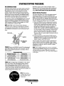
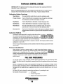
INTRODUCTION
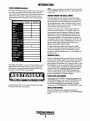
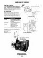
SERIAL NUMBER LOCATION
NOTE: A carbon monoxide warning decal has been provided
by WESTERBEKE. Affix this decal in a visible position in the
engine room.
The engine and generator serial numbers and model numbers
are located on a decal on the generator housing. Take the
time to enter this information on the illustration of the nameplate shown below, as this will provide a quick reference
when seeking technical information and/or ordering repair
parts.
..
UNDERSTANDING THE DIESEL ENGINE
The diesel engine closely resembles the gasoline engine,
since the mechanism is essentially the same. The cylinders
are arranged above a closed crankcilse;the crankshaft is of
the same general type as that of a gasoline engine, and the
diesel engine has the same type of valves, camshaft, pistons,
connecting rods and lubricating system.
Therefore, to a great extent, a diesel engine requires the
same preventive maintep.ance as a gasoline engine. The
most important factors are proper ventilation and proper
maintenance of the fuel, lubricating and cooling systems.
Replacement of fuel and lubricating filter elements at the
tin).e periods specified is a must, and frequent checking for
contamination (that is water, sediment, etc.) in the fuel system is also essential, Another important factor is the use of
the same brand of high detergent diesel lubrication oil
designed specifically for diesel engines.
The diesel engine does differ from the gasoline engine,
however, in its method of handling and firing of fuel. The
carburetor and ignition systems are replaced by a single
component - the fuel injection pump - which performs the
function of both.
~~~~~~
ORDERING PARTS
Whenever replacement parts are needed, always provide the
generator model number, engine serial number, and generator
serial number as they appear on the silver and black nameplate located on the generator end. You must provide us with
this information so we may properly identify your generator
set. In addition, include a complete part description and part
number for each part needed (see the separately furnished
Parts List). Insist upon WESTERBEKE packaged parts
because will fit or generic parts are frequently not made to
the same specifications as original equipment.
The engine serial number can also be found stamped into the
engine block just above the injection pump. The generator
serial number is stamped irito the generator housing on the
flat surface on the left side of the generator.
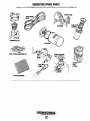
SPARES AND ACCESSORIES
Celtain spares will be needed to support and maintain your
WESTERBEKE engine. Your local WESTERBEKE dealer
will assist you in preparing an inventory of spare parts.
See the SPARE PARTS page in this manual. For engine
accessories, see WESTERBEKE'S ACCESSORIES brochure.
An identification plate on the engine manifold also displays
the engine model and serial number.
INSTALLATION MANUAL
Publi.cation #43400 provides detailed information for
installing generators and is available at your WESTERBEKE
dealer.
Engines & Generators
4
FUEL, ENGINE OIL AND ENGINE COOLANT
ENGINE COOLANT
FUEL
WESTERBEKE recommends a mixture of 50% antifreeze
and 50% distilled water. Distilled water is free from the
chemicals that can corrode internal engine surfaces.
A CAUTION: Only use unleaded fuel with an octane
rating of 89 or higher. Leaded fuel will cause serious
harm to your engine and violate your warranty.
The antifreeze performs double duty. It allows the engine
to run at proper temperatures by transferring heat away from
the engine to the coolant. It also lubricates and protects the
cooling circuit from rust and corrosion. Use a good quality
antifreeze that contains supplemental cooling additives
(SCAs') that keep the antifreeze chemically balanced, crucial
to long term protection.
Care Of The Fuel Supply
Use only clean fuel! The clearance of the components in
your fuel injection pump is very critical; invisible dirt
particles which might pass through the filter can damage
these finely finished parts. It is important to buy clean fuel,
and keep it clean. The best fuel can be rendered
unsatisfactory by careless handling or improper storage
facilities. To assure that the fuel going into the tank for your
engine's daily use is clean and pure, the following practice is
advisable:
The water and antifreeze should be premixed before being
poured into the cooling circuit.
NOTE: Use the new environmentally-friendly, long lasting,
antifreeze that is now available.
A proper 50/50 mixture as recommended will protect the
engine coolant to temperatures of -40°F.
Purchase a well-known brand of fuel.
COOLANT RECOVERY TANK
Install and regularly service a good, Coast Guard approved
metal bowl type filter/water separator between the fuel tank
and the engine.
A coolant recovery tank kit is supplied with each generator.
The purpose of this recovery tank is to allow for engine
coolant expansion and contraction during engine operation,
without the loss of coolant and without introducing air into
the cooling system.
ENGINE OIL
Use an engine oil regular or synthetic with an API classification of CF and/or CG-4. An oil viscosity rating of 15W-40 is
recommended for all operating conditions. Change the
engine lube oil and filter after the initial 50 hours of break-in
operation and every 100 hours or less of operations there
after.
A CAUTION: Do not allow two or more brands of
engine oil to mix. Each brand contains its own additives;
additives of different brands could react in the mixture
to produce properties harmful to your engine.
Engines & Generators
5
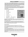
GENERATOR CONTROL PANELS
DESCRIPTION OF SWITCHES
EMERGENCY STOP: The EMERGENCY
stop switch on 1he side of the control box,
is normally closed. When depressed, it
will open the DC circuit to the control
panel and shut the engine down. As the
switch is not toggled it can be used when
performing maintenance.
This manually controlled series of WES1ERBEKE marine
diesel generators is equipped wi1h toggle switches on 1he
engine control panel and, optionally, at remote panels.
All three switches are momentary contact type and serve 1he
following functions:
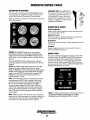
DESCRIPTION OF GAUGES
Coolant Temperature
Engine coolant (water) temperature should normally indicate
1750 to 1950 F (800 to 900 C).
Engine Oil Pressure
Oil pressure (psi) may fluctuate depending on the generator
load but should range be~een 35 to 55 psi.
DC Voltmeter
Indicates 1he amount the battery is being charged should show
13Vto 14V.
Hourmeter
Registers elapsed time and is used as a guide for when to
perform scheduled maintenance.
PREHEAT: The PREHEAT toggle serves two purposes:
preheating the engine for easy starting and bypassing the
engine oil pressure switch. The PREHEAT function closes
the K2 relay. as well as supplies current to the fuel" solenoid
pull coil.
When the PREHEAT switch is depressed, the voltmeter,
panel lights, gauges and meters and the hold coil of the fuel .
solenoid.
START: The START toggle switch closes the Kl relay that
energizes the starter solenoid and activates the starter.
While the PREHEAT switch is still depressed, depressing the
START switch engages the start solenoid. When the engine
begins to fire, the START switch should be released. The
PREHEAT switch should not be released until the oil
pressure reaches 5 - 10 psi.
STOP: The STOP toggle switch is a normally closed switch
providing power to the K2 relay. Opening of this switch
opens the power circuit to the fuel solenoid, stopping the
flow of fuel to the engine and shuts down 1he engine.
To stop 1he engine, depress 1he STOP switch. When the
STOP switch is depressed, the powe~ feed to the fuel solenoid is opened, and the fuel flow to the engine is stopped.
The STOP switch should be depressed until the generator
stops rotating
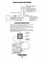
REMOTE PANEL
For remote operation of the generator system, the same three
switches are used. The PREHEAT and START switches are
connected in parallel with the gauge panel's switches and
serve the same functions as in the gauge panel. The STOP
switch is in series wi1h the gauge panel's STOP switch and
serves the same function. There is a REM01E START/STOP
WIRING DIAGRAM in this manual.
GENERATOR
6i
1
RELEASE
STARTER
STOP
PREHEAT
START
~
{~~
,{1ft)
MUST
PRESS
1ST
r~)
PRESS
2 ND
~
WESTERSEKE
NOTE: For additional infonnation on Control Panels. Refer to:
STARTING/STOPPING PROCEDURE, DC WIRING
DIAGRAMS and TROUBLESHOOTING GAUGES.
NOTE: When the engine is shut down, the water temperature
gauge and the oil pressure gauge will continue to register the
last temperature and oil pressure readings displayed. They
will return to zero once electrical power is restored.
Engines & Generators
6
PREPARATIONS FOR INITIAL START-UP
PRESTART INSPECTION
• Be sure that in power systems with a neutral line that
the neutral is properly grounded (or ungrounded) as the
system requires, and that the generator neutral is properly
connected to the load neutral. In single phase systems an
incomplete or open neutral can supply the wrong line-toneutral voltage on unbalanced loads.
Before starting your generator set for the first time or after a
prolonged layoff, check the following items:
• Check the engine oil level. Add oil to maintain the level at
the high mark on the dipstick.
• Check the fuel supply and examine the fuel filter/separator
bowls for contaminants.
• Check the DC electrical system. Inspect wire connections
and battery cable connections.
• Check the coolant level in both the plastic recovery tank
and at the manifold.
NOTE: After the initial running of the generator, the air in
the engine's cooling system should be purged through the
plastic coolant recovery tank. Allow the engine to cool
and then carefully remove the pressure cap on the
radiator. Ensure that the radiator is completely full of
antifreeze. If not, add mixture as needed to fill the
radiator. Replace the pressure cap and then add antifreeze
mixture to the plastic coolant recovery tank to fill it to half
way between "add" and "max".
• Visually examine the unit. Look for loose or missing
parts, disconnected wires, unattached hoses, and check
threaded connections. Search for any leaks.
• Check loiui leads for correct connection as specified in the
wiring diagrams.
• Examine air inlet and outlet for air flow obstructions.
• Be sure no other generator or utility power is connected to
load lines.
A CAUTION: When starting the generator, it is
recommended that all AC loads, especially large
motors, be switched OFF until the engine has come
up to speed and, in cold climates, starts to warm up.
This precaution will prevent damage caused by
unanticipated operation of the AC machinery and will
prevent a cold engine from stalling.
I
'-
RADIATOR
SIDE OIL FILL
Engines & Generators
7
TOP OIL FILL
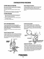
STARTING/STOPPING PROCEDURE
THE STARTING SYSTEM
Should the engine not start when the START switch is
depressed for 10 to 20 seconds, release both switches and
wait 30 seconds; repeat the procedure above and preheat
longer. Never run the starter for more than 30 seconds.
Westerbeke diesel generators use electric starters assisted by
glow plugs for both nonnal and cold weather starting. The
illustration below shows a cross-sectional view of one
cylinder. The glow plug is located in the pre-combustion
chamber so that its tip is in the injector nozzle's spray path.
When the glow plug is energized by the PREHEAT button,
the plug glows red at the tip and assists in igniting the fuel.
The result is a rapid start with less wear on the starter.
This system is common to WESTERBEKE diesels. The start
circuitry is designed so that the PREHEAT button must be
depressed for the time specified in the preheat chart. Then,
while keeping the PREHEAT button engaged, the START
button is depressed to crank the engine.
Remote Starting Procedure
The remote start panel is the same as the engine-mounted
start panel except that it has a green LED light and no
gauges. When starting at a remote location, the green LED
lights when the generator is running at approximately 600
rpm. This indicates when the START switch can be released
since the starting of the generator may not be audible.
A. When the PREHEAT switch is depressed at the remote
start/stop panel the LED light will illuminate. When the
START switch is depressed and the starter cranks the
engine this LED light will dim. When the engine starts
the LED light will brighten signaling to release the
START switch. Continue to hold the PREHEAT depressed
for a few seconds to allow oil pressure to build up which
closes the oil pressure safety switch that is in the series
path for 12V B+ to the K2 run relay/fuel run solenoid.
The green LED will remain brightly illuminated while the
engine is running.
B. After the generator is started and the START switch is
released, the generator's starter will not crank unless the
PREHEAT switch is operated first because this switch
supplies voltage to the START switch.
Once the engine starts, check the engine's instruments for
proper oil pressure and battery charging voltage. Apply a
light load to the generator and allow the engine's operating
temperature to come up to 140-1500 (60-660 C) before
applying heavy loads.
NOTE: The START switch will not energize unless the
PREHEAT switch is depressed. Depressing the PREHEAT
switch activates the glow plugs in the cylinder head so use
the PREHEAT intermittently to avoid overheating the glow
plugs.
GLOW PLUGS
. ~~~~~~ PRE-COMBUSTION
\'
CHAMBER
-------
PREHEAT: Depress the PREHEAT switch. The voltmeter and
panel lights, gauges and meters will be activated. The PREHEAT switch should be depressed in accordance with the
following chart:
Temperatu eJPreheat
Abnospherlc Temperatura
NOTE: Some unstable running may occur in a cold engine.
Depressing the PREHEAT switchfor 10-15 second intervals
will help stabilize the engine RPM until the operating
temperature reaches the 140 - 150 0 F and a load is applied
to the engine.
Preheating nme
Approx. 10 seconds
+41 °F(+5°C) or higher
+41°F(+5°C) to 23°F (-5°C)
+23°F(-5°C) or lower
limit of continuous usa
Approx. 15 seconds
Approx. 20 seconds
30 seconds before cranking
START: While still depressing the PREHEAT switch, depress
the START switch. This will engage the starter solenoid.
Upon engine starting, release the START switch. Do not
release the PREHEAT switch until the oil pressure reaches
15 psi. Then as long as the high water temperature and low
oil pressure protective circuits do not activate, the engine will
remain energized and continue to run.
12
14
I
~6
\
t::l \"""
"'
NOTE: When starting:
. A voltage drop will occur
when the preheat switch
is depressed.
VOLTS
Engines & Generators
8
STARTING/STOPPING PROCEDURE
STARTING UNDER COLD CONDITIONS
Remote Stopping Procedure
To stop the generator, depress the STOP switch which opens
the normally closed B+ path for voltage to the engine's run
circuit. The STOP switch must be held open until the
generator comes to a complete stop and the green LED light
goes out.
. Make sure !he lubricating oil conforms with the ratings for
the prevailing temperature. Check the table in the ENGINE
OIL section in this manual.
The battery should be fully charged to minimize voltage
drop .
.use a sufficient amount of prehea~ to aid in starting. See the
Temperature!Preheat chart elsewhere in this section.
STOPPING PROCEDURE
1. Remove the AC electrical load from the generator and
allow the generator to run for three to five minutes to
stabilize its operating temperatures.
2. Depress the STOP switch and hold it until the generator
is completely stopped.
3. Now release the STOP switch.
. SAFETY SHUTDOWN SWITCHES
Low Oil Pressure Switch
The engine is protected by three automatic shutdown
switches. Should shutdown occur, do not attempt to restart
without finding and correcting the cause. Refer to the
heading "Engine Stops" in the TROUBLESHOOTING
section of this manual.
. The following is a description of these automatic shutdown
switches:
A low oil pressure shutdown switch is located off the
engine's oil gallery. Normally open in a static state, this
switch's sensor monitors the engine's oil pressure. Should the
engine's oil pressure fall to 5-10 psi, this switch will open,
interrupting the DC voltage to the K2 relay, thereby shutting
off the engine.
.
Coolant Temperature Switch
A high water temperature switch is' located on the thermostat
housing. Nonnally closed, this switch, should the fresh water
coolant's operating temperature reach approximately 2100 P
(99°C), will open and interrupt the DC voltage to the K2'
relay, thereby shutting off the engine. Tins switch resets at
195°P (107°C).
OIL GALLERY
THERMOSTAT
ASSEMBLY
OIL PRESSURE
SWITCH
OIL PRESSURE SWITCH
WIRED FOR OPTIONAL
.AUDIBLE ALARM
Engine Circuit Breaker
The generator's engine is protected by an engine mounted
manual reset circuit breaker (20 amps DC). Excessive current
draw or electrical overload anywhere in the instrument panel
wiring or engine wiring will cause the breaker to trip. In this
event the generator will shut down and the voltage to the K2
relay is terminated. If this should occur, check and repair the
source of the problem. After repairing the fault, reset the
breaker and restart the generator.
Engines & Generators
9
GENERATOR BREAK-IN PROCEDURE
DESCRIPTION
After the first 10 hours of the generators operation, the
load can be increased to the full-load rated output, then
periodically vary the load.
Although your engine has experienced a minimum of one
hour of test operations at the factory to make sure accurate
assembly procedures were followed and that the engine
operated properly, a break-in time is required. The service
life of your engine is dependent upon how the engine is
operated and serviced during its initial hours of use.
Breaking-in a new engine basically involves seating the
piston rings to the cylinder walls. Excessive oil consumption
and smoky operation indicate that the cylinder walls are
scored, which is caused by overloading the engine during the
break-in period.
Your new engine requires approximately 50 hours of initial
conditioning operation to break in each moving part in order
to maximize the performance and service life of the engine.
Perform this conditioning carefully, keeping in mind the
following:
Start the engine according to the STARTING PROCEDURE
section. Run the engine while checking that all systems (raw
water pump, oil pressure, battery charging) are functioning.
reach its full rated speed are signs of an overload.
Avoid overload at all times. An ovefload is signaled by a
smoky exhaust with reduced output voltage and frequency.
Monitor the current being drawn from the generator and keep
it within the generators' rating. Since the generator operates at
1800 rpm to produce 60 hertz, or at 1500 to produce 50 hertz,
control of the generators engine break-in is governed by the
current drawn from the generator.
NOTE: Be aware of motor starting loads and the high
current drawn required for starting motors. This starting
amperage draw can be 3 to 5 times normal running
amperage. See GENERATOR INFORMATION in this manual.
GENERATOR ADJUSTMENTS
Once the generator has been placed in operation, there may be
governor adjustments required for engine speed (hertz) during
the engine's break-in period (first 50 hours) or after this
period (see ENGINE SPEED (HERTZ) ADJUSTMENT under
ENGINE ADJUSTMENTS. A no-load voltage adjustment may
also be required in conjunction with the engine's speed adjustment (see GENERATOR INFORMATION).
AFTER START-UP
Once the generator has been started, check for proper operation and then encourage a fast warm-up. Run the generator
between 20% and 60% of full load for the first 10 hours.
THE DAILY ROUTINE
CHECK LIST
NOTE: Some unstable running may occur in a cold engine.
Follow this checklist each day before starting your generator.
This condition should abate as normal operating temperature
is reached and loads are applied.
• Check that all generator circuit breakers (power panel) are in
the off position before starting.
• Record the hourmeter reading in your log (engine hours relate
to the maintenance schedule).
A CAUTION: Do not operate the generator for long
periods of time without a load being placed on the
generator.
• Visually inspect the engine for fuel, oil, or water leaks.
• Check the oil level (dipstick).
STOPPING THE GENERATOR
• Check the coolant level in the coolant recovery tank.
Remove the AC loads from the generator one at a time. Allow
the generator to run for 3-5 minutes to stabilize the operating
temperature, then turn the key to the off position. Once the
generator is shutdown, close down all circuit breakers as a
safety precaution.
• Check your fuel supply.
• Check the starting batteries (weekly).
• Check the drive belt for wear and proper tension (weekly).
CHECK WITH THE ENGINE RUNNING.
• Check for abnormal noise such as knocking, vibration and
blow-back sounds.
• Confirm exhaust smoke:
When the engine is cold - White Smoke.
When the engine is warm - almost Smokeless.
When the engine is overloaded - some Black Smoke.
Engines & Generators
10
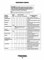
MAINTENANCE SCHEDULE
A WARNING: Never attempt to perform any service while the engine is
running. Wear the proper safety equipment such as goggles and gloves, and
use the correct tools for each job. Disconnect the battery terminals when
servicing any of the engine's DC electrical equipment.
NOTE: Many of the following maintenance jobs are simple but others are more
difficult and may require the expert krwwledge of a service mechanic.
SCHEDULED
MAINTENANCE
Fuel Supply
CHECK
EACH
DAY
HOURS OF OPERATION
50
100
250
500
750 1000 1250
EXPLANATION OF SCHEDULED
MAINTENANCE
Diesel No.2 rating of 45 cetane or higher.
Fuel/Water Separator
0
0
Engine Oil Level
0
Oil level should indicate between MAX. and LOW on
dipstick.
Coolant Level
0
Check at recovery tank; if empty, check at manifold.
Add coolant if needed.
0
Inspect for proper tension (3/8" to 1/2" deflection)
and adjust if needed. Check belt edges for wear.
Drive Belts
Check for water and dirt in fuel (drain/replace filter
if necessary).
weekly
Visuallnspeclion of Engine
0
NOTE: Please keep engine surface clean. Dirt
and oil will inhibit the engine's ability to
remain cool.
Fuel Filter
Starting Batteries
0
0
0
0
0
0
Check for fuel, oil and water leaks. Inspect wiring
and electrical connections. Keep bolts & nuts tight.
Check for loose belt tension.
Initial change at 50 hrs, then change every 250 hrs.
Every 50 operating hours check electrolyte levels
and make sure connections are very tight. Clean off
excessive corrosion.
0
weekly
Engine 011 (and filter)
0
0
0
0
0
0
0
Initial engine oil & filter change at 50 hrs., then
change both every 100 hours.
Generator
0
0
0
0
0
0
0
Check that AC connections are clean and secure
with no chafing. See GENERATOR SECTION
for additional information.
0
0
0
0
0
0
0
Change every 200 hours.
Fuel/Water Separator
Electronic Governor Control
(If applicable)
Exhaust System
Engine Hoses
0
0
0
0
0
Check and or adjust the no-load speed in the panel,
required (hertz) and the regulator board adjustment
as needed.
NOTE: These adjustment are not a warrantable
adjustment during or after the unit's break-in.
0
0
0
0
0
Initial check at 50 hrs., then every 250 hrs. Inspect
the system and that connections are tight and
secure. Ensure that the muffler and piping are
properly supported and not being affected by
vibration or chaffing.
0
Hose should be hard & tight. Replace if soft or
spongy. Check and tighten all hose clamps.
Engines & Generators
11
MAINTENANCE SCHEDULE
NOTE: Use the engine hour meter gauge to log your engine hours or record your
engine hours by running time.
SCHEDULED
MAINTENANCE
CHECK
EACH
DAY
HOURS OF OPERATION
50
100
250
Coolant System
500
D
EXPLANATION OF SCHEDULED
MAINTENANCE
750 1000 1250
D Drain, flush, and refill cooling system with
appropriate antifreeze mix.
Electric Fuel (ift
Pump
D
DC Alternator
D
D
D
D
D
D
*Fuellnjectors
D
Periodically check the wiring connections ..
D
Check DC charge from alternator. Check mounting
bracket; tighten electrical connections.
Check and adjust injection opening pressure and
spray condition (see ENGINE ADJUSTMENTS).
D
*Starter Motor
D
D
Check solenoid and motor for corrosion. Remove
and lubricate. Clean and lubricate the starter motor
pinion drive.
*Preheat Circuit
D
D
Check operation of preheat solenoid. Remove and
clean glow plugs; check resistance (4-6 ohms).
*Englne Cylinder
Compression
D
D
Check compression pressure and timing
(see ENGINE ADJUSTMENTS).
*Torque Cylinder Head
Hold-down bolts
D
D
D
At first 50 hours, then every 500 hours
(see ENGINE ADJUSTMENTS).
*Adjust the Valve Clearances
D
D
D
Adjust Valve Clearances
(see ENGINE ADJUSTMENTS).
D
Remove, have professionally cleaned and pressure
tested.
*Radlator
*WESTERBEKE recommends this service be performed by an authorized mechanic.
Engines & Generators
12
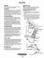
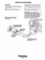
FUEL SYSTEM
DIESEL- FUEL
ENGINE FUEL FILTER
Use No.2 diesel fuel with a cetane rating of 45 or higher.
Do not use kerosene or home heating fuel.
Periodically check the fuel connections and the bowl for
leakage. Replace the filter element after the first 50 hours
then follow the MAINTENANCE SCHEDULE.
FUEL FILTERS
The fuel injection pump and the fuel injectors are precisely
manufactured and they must receive clean diesel fuel, free
from water and dirt. To ensure this flow of clean fuel, the fuel
must pass through at least two fuel filters, a fuel water
separator and the engine's spin-on fuel filter. VIsually inspect,
clean, and change these filters according to the maintenance
schedule in this manual.
FUEL WATER SEPARATOR
A primary fuel filter of the water separating type must be
installed between the fuel tank and the,engine to remove
water and other contaminants from the fuel before they can
be carried to the fuel system on the engine.
The owner/operator is responsible for making certain the
fuel reaching the engine's injectlQn equipment is free of
impurities. This process is accomvij.shed by installing and
maintaining a proper fuel filter/water separator between the
fuel tank and the generator/engine. Westerbeke recommends
.a 10 micron filter be used.
Changing/cleaning the filter element
1. Shut off the fuel supply.
2. Unscrew the retainer ring that holds the filter bowl to the
housing and allow the bowl to come away from the
housing,
3. Remove and replace the filter element and clean the bowl.
4. Replace the sealing "0" ring and reassemble the bowl
to the housing. Thread the retainer ring on carefully
so as not to cross thread. When retainer contacts the
"0" ring, tighten 114 - 112 turns by hand. Open the fuel
supply and run the engine to inspect for leaks.
FUEL INJECTION PUMP
The fuel injection pump is the most important component of
the diesel engine, requiring the utmost caution in handling.
The fuel injection pump has been thoroughly bench-tested
and the owner-operator is cautioned not to attempt to service
it. If it requires servicing, remove it and take it to an
authorized fuel injection pump service facility. Do not
attempt to disassemble and repair it. Do not send the timing
shims with the injection pump, leave on engine.
The only adjustment the servicing mechanic should make to
the fuel injection pump is the adjustment for the engines
running speed (see IDLE SPEED ADJUSTMENT under
LIGHTLY WIPE
WITH CLEAN FUEL
THE O-RING GASKET
ONLY NEEDS TO BE
REPLACES IF IT SHOWS"
SIGNS OF AGING.
ENGINE APJUSTMENTS).
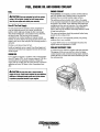
FUEL LIFT PUMP
FUEL
FILTER
Periodically check the fuel connections to aud out of the pump
and make sure that no leakage is present and that the fittings
are tight and secure. The DC ground connection at one of the
pump's mounting bolts should be clean and well secured by
the mounting bolt to ensure proper pump operation.
When energized thru the preheat circuit, the fuel lift pump will
purge air from the fuel system and provide a continuous flow
of fuel as the engine is running.
INLET FUEL FILTER
To ensure clean fuel into the fuel lift pump, there is a small
in-line fuel filter connected to the fuel lift pump elbow. This
filter should be replaced every 250 hours of operation.
FUEL LIFT PUMP
Engines & Generators
13
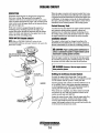
COOLING CIRCUIT
DESCRIPTION
When the engine is started cold, external coolant flow is prevented by the closed thennostat (although some coolant flow
is bypassed around the thermostat to prevent the engine from
overheating). As the engine warms up, the thermostat gradually opens, allowing full flow of the engine's coolant to flow
unrestricted to the external portion of the cooling system.
Westerbeke diesel engines are designed and equipped for
fresh water cooling. Heat produced in the engine by
combustion and friction is transferred to fresh water coolant
which circulates throughout the engine. This circulating fresh
water coolant cools the engine block and its internal moving
parts and the engine oil.
Fresh water coolant is pumped through the engine by a
circulating pump, absorbing heat from the engine. The
coolant then passes through the thermostat into the radiator
where it is cooled, and returned to the engine block via the
suction side of the circulating pump.
Coolant Recovery Tank
A coolant recovery tank allows for engine coolant expansion
and contraction during engine operation, without any
significant loss of coolant and without introducing air into
the cooling system. This tank should be located at or above
the engine manifold level and should be easily accessible.
FRESH WATER COOLING CIRCUIT
CHANGING COOLANT
NOTE: Refer to ENGINE COOlANT section for the
The engine's coolant must be changed according to the
recommended antifreeze and water mixture to be used as the
fresh water coolant.
MAINTENANCE SCHEDULE. If the coolant is allowed to
become contaminated, it can lead to overheating problems.
A CAUTION: Proper cooling system maintenance is
critical; a substantial number of engine failures can be
traced back to cooling system corrosion.
Drain the engine coolant by removing the drain plug under
the manifold and opening the manifold pressure cap. Flush
the system with fresh water, then start the refill process.
A WARNING: Beware of the hot engine coolant.
Wear protective gloves.
Refilling the Antifreeze Coolant System
Re-install the engine block drain plug. Close the drain
pluglpetcock on the radiator. Pre-mix your antifreeze and add
it to the radiator until the system is visibly near full.
Start the generator and continue to add the antifreeze mix as
air is expelled. Observe the engine operating temperature.
As the temperature nears 180°F. The thermostat should be
opening and flow through the radiator observed.
When all the air is expelled, top off the radiator and install
the pressure cap, now add more antifreeze mixture to the
remote recovery tank until half full.
Inspect the system for any leaks. Stop the engine and allow
the system to cool down. Coolant in the plastic coolant
•
recovery tank should be drawn into the engines cooling
system. Add enough coolant to the recovery tank to place the
level between the add and max marks.
Engines & Generators
14
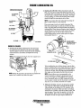
ENGINE COOLING CIRCUIT
THERMOSTAT
TO COOLANT
; RECOVERY TANK
FROM COOLANT
RECOVERY TANK
COOLANT EXPANSION
A thermostat, located near the front of the engine, controls
the engine's coolant temperature, as the coolant continuously
flows through the engine's closed cooling system.. When the
engine is first started and the thermostat is closed, engine
coolant by passes the thermostat to provide proper circulation
and cooling via a by-pass hose located between the circulating pump and below the thermostat. As the engine coolant
reaches operating temperature, the thermostat gradually
opens to allow coolant to flow through it. The thermostat is
accessible and can be checked. cleaned or replaced as
needed. Carry a spare thermostat and housing gasket.
To Replace the Thermostat
Remove the cap screws and disassemble the thermostat
housing as shown. When installing the new thermostat and
gasket, apply a thin coat of sealant on both sides of the
gasket before pressing it into place. Do not over-tighten the
cap screws.
Roo the engine and check for normal temperatures and that
there are no leaks at the
housing.
COOLANT RETRACTION
NOTE: Periodically check the condition of the radiator
pressure cap. Ensure that the upper and lower rubber seals
are in good condition and check that the vacuum valve opens
and closes tightly. Carry a spare cap.~_ _
RUBBER
~_.-.,-.rfiJ
. AIR INTAKE FILTER/SILENCER
There is a replaceable paper intake filter that should be
inspected every 100 hours of unit operation or more frequently in dusty operating conditions. Contaminants in the
filter can be shaken out or removed with the aid of compressed air. However, if this can not be accomplished the element/filter must be replaced.
NOTE: T9 operate efficiently a diesel ~ngine must intake a
continuous volume of clean air. Hard starting, an erratic idle,
and black exhaust smoke are all symptoms of a restricted air
intake.
~--AIR
SCREEN
. FILTER
III,
II
COOLANT
TEMPERATURE.
SENDER
AIR INTAKE
SILENCER·
15
GASKET
SEAL WITH HI-TACK
ENGINE LUBRICATING OIL
LUBRICATION DIAGRAM
2. Replacing the Oil Filter. When removing the used oil
filter, you may find it helpful and cleaner to punch a hole
in the upper and lower portion of the old filter to drain the
oil from it into a container before removing it. Thls helps
to lessen spillage. A small style automotive filter wrench
should be helpful in removing the old oil filter.
OIL PRESSURE
SENDOR
NOTE: Do not punch this hole without first loosening the
filter to make certain it can be removed!
OIL PRESSURE -~-:ItlIIIIDoii""
SWITCH
Place some paper towels and a plastic bag around the
filter when unscrewing it to catch any oil left in the filter.
(Oil or any other fluid on the engine reduces the engine's
cooling ability. Please keep your engine clean.) Inspect the
old oil filter as it is removed to make sure that the rubber
sealing gasket came off with the old oil filter. If this
rubber sealing gasket remains sealed against the engine
block, gently remove it.
.
1!!!II'iZ!1oI-IJ--1"- SEALING
GASKET
, COAT WITH CLEAN OIL
WHEN INSTALLING
'
ENGINE OIL CHANGE
1. Draining the Oil Sump. Discharge the used oil through
the sump drain hose (attached to the front of the engine)
while the engine i~ still warm. Drain the used oil completely,
replace the hose in its bracket, and replace the end cap
securely.
NOTE: Thread size
oil drain hose capped end is .
airiin-11/16"
7/i1l!tl'!'il~ :SOCKET
1W~NPT-
When installing the new oil filter element, wipe the filter
gasket's sealing surface on the engine block free of oil and
apply a thin coat of clean engine oil to the rubber gasket
on the new oil filter. Screw the filter onto the threaded oil
filter nipple, and then tighten the filter firmly by hand.
NOTE: Generic filters are not recommended, as the
, material standards dr diameters of important items on
generic parts might be entirely different from genuine
parts. Immediately after an oil filter change and oil fill,
rWl the engine to make sure the oil pressure is normal and
that there are no oil leaks around the new oil filter.
NOTE: During this procedure, fuel and oil may spill from the
engine, have a suitable tray under the engine.
3. Filling the Oil Sump. Add new oil through the oil filler
cap on the top of the engine or through the side oil fill..
After refilling, run the engine for a few moments while
checking the oil pressure. Make sure there is no leakage
around the new oil filter or from the oil drain system, and
stop the engine. Then check the quantity of oil with the
lube oil dipstick. Fill to, but not over the high mark on
the dipstick, should the engine require additional oil.
Engines & Generators
16
REMOTE OIL FILTER (OPTIONAL)
To install, simply remove the engine oil filter and thread on
WESTERBEKE'S remote oil filter kit as shown. Always
install this kit with the oil filter facing down as illustrated.
INSTALLATION
This popular accessory is used to relocate the engine's oil
filter from the engine to a more convenient location such as
an engine compartment.
Contact your WESTERBEKE dealer for more information.
NOTE: Refer to the ENGINE OIL CHANGE page in this
manual for instructions on removing the oil filter.
NOTE: Westerbeke is not responsible for engine failure due to
incorrect installation of the Renwte Oil Filter.
A CAUTION: It is vital to install the oil lines
correct/yo If the oil flows in the reverse direction, the
by-pass valve in the filter assembly will prevent the oil
from reaching the engine causing an internal engine
failure. If there is ;'0 oil pressure reading, shutdown
immedialety and check the hose connections
APPLY A THIN COAT OF CLEAN OIL TO THE O-RING WHEN
INSTAlliNG THIS KIT. THREAO THE KIT ON, THEN HAND
TIGHTEN AN ADDITIONAL 3/4 TURN AFTER THE O-RING
CONTACTS THE BASE.
FASTEN SECURELY TO A BULKHEAD
(SCREWS ARE OWNER SUPPLIED)
V
NOTE THE "IN" AND "OUT" MARKINGS
ON THE ADAPTER WHEN THE HOSES ARE
REMOVED FOR INSTAlLATION SO THEY
, Will BE RECONNECTED CORRECtlY.
THE OUT CONNECTION HOSE
MUST ATTACH TO THE IN
CONNECTION AT THE
REMOTE OIL FILTER.
APPLY A THIN COAT OF CLEAN OIL TO THE FILTER GASKET WHEN INSTALLING. AFTER THE
FIlTER CONTACTS THE BASE, TIGHTEN IT AN
ADDITIONAL 3/4 TURN.
Engines & Generators
17
STARTER MOTOR
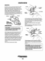
DESCRIPTION
The starter is a new type, small, light-weight and is called a
high-speed internal-reduction starter. The pinion shaft is
separate from the motor shaft; the pinion slides only on the
pinion shaft. A reduction gear is installed between the motor
shaft and a pinion shaft. The pinion sliding part is not
exposed outside the starter so that the pinion may slide
smoothly-without becoming fouled with dust and grease. The
motor shaft is supported at both ends on ball bearings. The
lever mechanism, switch and overrunning clutch inner circuit
are identical to conventional ones.
TERMINALS --~
SOLENOID
r-...----(M) TERMINAL
IGNITION
TERMINAL
SOLENOID
To test the ignition circuit, locate the ignition(s) terminal (it
is one of the small terminal studs and is wired to the ignition
circuit). Use a screwdriver, don't touch the blade, to jump
from that ignition terminal to the positive battery connection
terminal on the solenoid.
If the starter cranks, the fault lies with the ignition
circuit.
If the solenoid clicks but nothing happens, the starter
motor is probably faulty.
MOTOR
TYPICAL
STARTER MOTOR
REFER TO THE WIRING
DIAGRAM IN THIS MANUAL
TROUBLESHOOTING
A WARNING: The following emergency starting
SOLENOID
procedures must not be used with gasoline engines.
Sparks could cause an explosion and fire.
Prior to testing, make certain the ships batteries are at full
charge and that the starting system wiring connections
(terminals) are clean and tight. Pay particular attention to
the ground wire connections on the engine block.
To check the wiring, try cranking the starter for a few
seconds, never more than 10 seconds at a time, then run your
hand along the wires and terminals looking for warm spots
that indicate resistance. Repair or replace any trouble spots.
Using a multimeter, test the voltage between the positive
terminal stud on the start solenoid and the engine block
(ground).
If you read 12 volts, the starter is faulty.
~
IGNITION
TERMINAL
~
If nothing happens at all, the solenoid is not getting
current.. Check the battery isolation switch and inspect the
wiring connections. it is also possible that the solenoid is
defective.
A WARNING: There will be arching and sparks will
fly when jumping terminals. Be certain the engine
space is free of potentially explosive fumes, especially
gasoline, and that there are NO flammable solvents or
materials stored nearby.
Engines & Generators
18
STARTER MOTOR
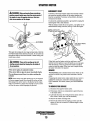
EMERGENCY START
·A WARNING: When perfonning these procedures,
Corrosion to the starter brushes and/or the solenoid contacts
can cause the sporadic problem of the engine starting one
time but not another. If corrosion is the problem, the starter
will need to be rebuilt.
It is however, sometimes possible to get started by taping the
starter lightly with a small hammer.
With the battery switch off and no ignition,. tap lightly on the
starter/solenoid casing as shown, then try to start the engine.
, position yourself safely away from the moving parts of
! the engine In case the engine starts-up. Also wam
, other crew members of the danger.
...
~-.:----(M)
TERMINAL
\ TAP LIGHTLY WHERE
. INDICATED
'iGNITION
TERMINAL
Test again by jumping the two large tenninal studs. Hold the
Screwdriver blade finnly between the studs. Do not allow the
screwdriver blade to touch the solenoid or starter casing, this
would cause a short.
A WARNING: There will be arching as the full
If that fails, turn the battery switch on and have a crew
member turn the ignition on and off rapidly as you tap again
with the hammer., This may loosen the brushes and allow
contact to start the engine. When you reach a repair facility,
the starter will need to be repaired.
starting current should be nowlng thru the blade of
the screwdriver.
If the starter spins, the solenoid is faulty.
SERVICE
if the starter fails to spin, the motor is probably faulty.
WESTERBEKE uses a standard starter motor which can be
serviced or rebuilt at any starter motor automotive service
center,
If replacing the starter motor, make certain the new motor is
certified for marine use. Automotive starters do not meet
USCG standards. If in doubt, Gontact your WESTERBEKE
dealer.
.tt no arching occurred, there is no juice reaching the
solenoid.
NOTE: Starter motors are either inertia type or pre-engaged.
In the pre-engaged model, the solenoid also moves an arm
that engages the starter motor to the flywheel of the engine.
using a screwdriver to bypass the solenoid on such a starter
will run the motor without engaging the flywheel.
TO REMOVE FOR SERVICE
1. Disconnect the negative battery cable.
2. If necessary, remove any components to gain full access
to the starter motor.
3. Label and disconnect the wiring from the starter. (Do not
allow wires to touch, tape over the terminals).
4. Remove the starter mounting bolts.
5. Remove the starter from the engine. In some cases the
starter will have to be turned to a different angle to clear
obstructions,
Engines & Generators
19
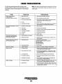
ENGINE TROUBLESHOOTING
Note: The engine s electrical system is protected by a 20 amp
manual reset circuit breaker located on a bracket at the rear
of the engine.
The following troubleshooting table describes certain
problems relating to engine service, the probable causes of
the problems, and the recommendations to overcome these
problems.
Problem
PREHEAT switch depressed:
no panel indications;
fuel solenoid or electrical fuel pump
Probable Cause
Verlflcation/Remedy
1. Battery Switch not on.
1. Check switch and/or battery connections.
2. Emergency stop switch off.
2. Check emergency stop switch position.
3. 20-Amp circuit breaker tripped.
2. Reset breaker; if breaker trips again, check preheat solenoid
circuit and check circuit for shorts to ground.
4. K2 relay
3. Check K2 relay.
5. loose battery connections.
4. Check (+) connection to starter solenoid and (-) connection to
engine ground stud. Check battery cable connections.
1. Connection to solenoid faulty.
1. Check connection.
2. Faulty switch.
2. Check switch with ohmmeter.
3. Faulty solenoid.
3. Check that 12 volts are present at the solenoid connection.
4. loose battery connections.
4. Check battery connections.
5. low battery.
6. Kl relay.
5. Check battery charge state.
START switch is depressed; panel
indications OK; starter solenoid OK
fuel solenoid not functioning.
1. Poor connections to fuel solenoid.
1. Check connections.
2. Defective fuel solenoid.
2. Check that 12 volts are present at the (+) connection on the
Generator engine cranks, but does not
start, fuel solenoid energized.
1. Faulty fueling system.
1. Check that fuel valves are open.
la. Switch to combine house and start batteries.
1b. Replace batteries.
le. Check fuel lift pump.
1d. Change inlet fuel filter.
START SWITCH DEPRESSED, no starter
engagement.
6. Check K1 relay.
fuel run solenoid.
2. Preheat solenoid faulty.
2. Check solenoid.
Engine can't be stopped.
1. Faulty DC alternator.
1. Remove "R" connection at alternator, repair alternator.
Battery runs down.
1. Oil Pressure switch.
1. Observe if gauges and panel lights are activated when engine
is not running. Test the oil pressure switch.
2. High resistance leak to ground.
2. Check wiring. Insert sensitive (0 - .25 amp) meter in battery
lines. Do not start engine. Remove connections and replace
after short is located.
3. low resistance leak.
3. Check all wires for temperature rise to locate the fault.
4. Poor battery connections.
4. Check cable connections at battery for loose connections,
corrosion.
5. DC alternator not charging.
5. Check connections, check belt tension. test alternator. See
1. DC charge circuit faulty.
1. Perform D.C. voltage check of generator charging circuit. See
DC ELECTRICAL SYSTEM/ALTERNATOR in this manual.
2. Alternator drive.
2. Check drive belt tension. Alternator should turn freely. Check
DC ELECTRICAL SYSTEM/ALTERNATOR.
Battery not charging
for loose connections. Check output voltmeter. Ensure 12 volts
are present at the Exc. terminal.
Engines & Generators
20
ENGINE TROUBLESHOOTING
Problem
Generator engine stops.
Probable Cause
VerificationJRemedy
1. Fuel feed pump strainer is dirty.
1. Clean strainer (32 KW only).
2. Switches and/or wiring loose
or disconnected.
2. Inspect wiring for short circuits and loose connections.
Inspect switches for proper operation.
3. Fuel starvation.
3. Check fuel supply, fuel valves, fuel feed strainer.
4. 20 Amp circuit breaker tripping.
4. Check for high DC amperage draw during operation.
Ensure breaker is not overly sensitive to heat which would
cause tripping.
5. Exhaust system is restricted.
6. Water in fuel.
5. Check for blockage or collapsed muffler.
7. Air intake obstruction.
7. Check air intake filter cartridge.
1. Coolant not circulating.
1. Thermostat - remove and test in hot water.
Replace thermostat.
6. Pump water from fuel tank(s); change filters and
bleed fuel system.
Generator engine overheats/shuts down.
1a. Loss of coolant - check hoses, hose clamps, drain plug, etc.
for leaks.
1b. Broken or loose belts - tighten/replace.
1c. Air leak in system; run engine and open the pressure cap to
bleed air. Add coolant as needed.
Generator engine shuts down,
Low oil pressure.
Exhaust smoking problems
1. Loss of oil.
1. Check dipstick, look for oil leaks at oil filter and at
oil drain hose connection.
2. Oil pressure switch.
2. Replace oil pressure switch.
1. Blue smoke.
1. Incorrect grade of engine oil.
1a. Crankcase is overfilled with engine oil (oil is blowing out
through the exhaust).
2. White smoke.
2. Engine is running cold.
3. Black smoke.
3. Improper grade of fuel.
2a. Faulty injector or incorrect injector timing.
3a. Fuel burn incomplete due to high back pressure in exhaust or
insufficient air for proper combustion (Check for restrictions in
exhaust system; check air intake.).
3b. Improperly timed injectors or valves or poor compression.
3c. Lack of air - check air intake and air filter. Check for proper
ventilation.
3d. Overload.
Engine starts, runs and shuts down
Engine starts, runs at idle
1. Oil pressure switch.
1. Check oil pressure switch.
2. Water temperature switch.
2. Check water temperature switch.
1. Electronic governor system faulty
(optional system)
1. Check governor system components.
Engines & Generators
21
ENGINE ADJUSTMENTS
NOTE: WESTERBEKE recommends that the following enginE! adjust~
ments be performed by a competent engine mechanic. The information
below is provived to assist the mechanic.
DRIVE BELT ADJUSTMENT (FAN BELT)
TORQUING THE CYLINDER HEAD BOLTS
For your safety, WESTERBEKE generator models come .
equipped with belt guards that cover over the belt(s) on the
front of the engine. ("Out of sight - out of mind." The belt
guard is NOT installed for that purpose.) Operators are
advised that proper inspection, service, and maintenance is
required.
After the initial break-in period (approximately 50 hours) and
every 500 hours thereafter, the cylinder head bolts should be
re-torqued.
Tighten the cylinder head bolts according to the sequence
shown. Make sure the engine is cold when this is done.
Before applying the specified torque to the bolt, lom;en it
114 to 112 of a turn and then apply the torque. Follow this
procedure according to the numbered sequence shown in the
illustration to the right.
Excessive drive belt tension can cause rapid wear of the belt
and reduce the service life of the fresh water pump's bearing.
A slack belt or the presence of oil on the belt can cause belt
slipping, resulting in high operating temperatures.
Bolts #1,2, and 3, (12mm socket) 14 - 22 ft-Ib
Bolts #4,5,6, 7, 8, (14mm socket) (54 -- 61 ft-Ib)
Rockershaft Hold Down Bolts - 12mm socket (11 - 16 ft-lb).
The drive belt is properly adjusted if the belt can be
deflected no less than 3/8 inch (lOmm) and no more than lI2
inch (12mm) as the belt is depressed with the thumb at the
midpoint between the two pulleys on the longest span of the
belt. A spare belt or belts should always be carried on board.
A
WARNING: Never attempt to check or adjust the
drive belt's tension while the engine is in operation.
Adjusting Belt Tension
1. Remove the belt guard.
2. Loosen the pivot belt that holds the idler sheave and
loosen the adjusting bolt.
3. With the belt loose, inspect for wear, cracks and frayed
edges.
4. Pivot the idler sheave to the left or right as required, to
loosen or tighten.
CYLINDER HEAD BOLT PATTERN
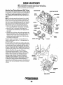
FUEL INJECTORS
In case of severe vibrations and detonation noise, have the
injectors checked and overhauled by an authorized fuel
injection service center. Poor fuel quality, contaminant's and
loss of positive fuel pressure to the injection pump can result
in injector faults. Since fuel injectors must be serviced in a
clean room environment, it is best to carry at least one extra
injector as a spare should a problem occur.
Before removing the old injector, clean the area around the
base of the injector to help prevent any rust or debris from
falling down into the injector hole. If the injector will not lift
out easily and is held in by carbon build-up or the like, work
the injector side-to-side with the aid of the socket wrench to
free it, and then lift it out.
S. Tighten the pivot bolt and the adjusting bolt.
6. Replace the guard. Operate the generator for about 5
minutes and then shut the generator down.
7. Remove the guard and recheck the belt tension.
8. Replace the guard.
The injector seats in the cylinder head on a copper sealing
washer. This washer should be removed with the injector and
replaced with a new washer when the new injector is
.
installed.
INJECTOR TO CYLINDER HEAD TIGHTENING TORQUE
40 ± 4 fI-lb (5.5 ± 0.5 kgf-m)
PIVOT BOLT
WHEN THE ENGINE IS RUNNING,
KEEP CLEAR OF THE FAN
AND ENGINE BELT.
Engines & Generators
22
ENGINE ADJUSTMENTS
VALVE CLEARANCE ADJUSTMENT
Re-install the glow plugs (use anti-seize compound on the
threads) and assemble the rocker cover and rocker cover
bolts. See TIGH1ENING TORQUE SCHEDULE in this
manual.
NOTE: Retorque the cylinder head bolts before adjusting the
engine's valves. See IDRQUING THE CYLINDER HEAD
BOLTS.
ENGINE COMPRESSION
A WARNING: Adjust the valve clearance when the
Check the compression pressure. To do this wann the engine,
remove all fuel injectors, or glow plugs, disconnect the fuel
shut-off solenoid wire, and install a compression adapter in
the injector hole or glow plug hole. Connect a compression
tester on the adapter and crank the engine with the starter
motor until the pressure reaches a maximum value. Repeat
this process for each cylinder. Look for cylinders with dramatically (at least 20%) lower compression than the average
of the others. Compression pressure should not differ by
more than 35.5 psi (2.5 kglcm2) at 280 rpm.
engine is cold. Valves are adjusted by cylinder in the firing order of the engine. Tighten the cylinder head bolts
to the specified torque before adjusting the valves.
Pull off the air breather pipe from the rocker cover and take
off the rocker cover bolts and the rocker cover to expose the
rocker shaft and valve assembly.
Remove the glow plugs from each of the cylinders to enable
the crankshaft to be easily rotated by hand to position each
cylinder for valve adjustment.
Valves·are adjusted with the cylinder in the piston being
adjusted at Top Dead Center (IDC) of its compression
stroke. Each cylinder is adjusted following the engine's firing
order (1-3-2 for WES1ERBEKE three cylinder engines).
Valve adjustment beginning with cylinder #1. Rotate the
crankshaft slowly and observe the operation of the valves for
cylinder #1. Watch for the intake valve to open indicating the
piston is on it's intake stroke (the piston is moving down in
the cylinder). Continue to rotate the crankshaft slowly and
look for the intake valve to close. This indicates the piston is
now starting it's compression stroke (the piston is moving up
in the cylinder towards IDC).
Align the IDC mark on the crankshaft front pulley with the
timing marker on the front gear case cover when positioning
the #1 Piston at IDC of it's compression stroke. Confirm this
by rotating the crankshaft approximately 20 degrees before
and after this point and the two valves for the #1 cylinder
should not move.
Standard compression pressure 398 Ib/iR' at 280 rpm (28.0 kg/em')
IT a weak cylinder is flanked by healthy cylinder, the problem
is either valve or piston related. Check the valve clearances
for the weak cylinder, adjust as needed and test again. If the
cylinder is still low, apply a small amount of oilmto the
cylinder to seal the rings and repeat the test. If compression
comes up - the rings are faulty.
Abnormally high readings on all cylinders indicates heavy
carbon accumulations, a condition that might be
accompanied by high pressUres and noise.
NOTE: In case of severe vibrations and detonation noise, the
cause may be fuel injector problems, see FUEL INJECmRS. Poor fuel quality, contaminates and loss ofpositive
fuel pressure to the injection pump will result in injector
faults.
When re-installing the glow plugs use anti-seize compound.
VALVE CLEARANCE
~,,,~=.mnn~
~
~
~
I
COMPRESSION TESTER
0.25 mm (0.010 in)
COLD ENGINE
ADAPTER~
Adjust the valves in #1 cylinder for both intake and exhaust.
Proceed to the next cylinder in the firing order.
Rotate the crankshaft 240 degrees in the normal direction of
rotation arid adjust the next cylinder's valves in the firing
order. Rotate the crankshaft another 240 degrees and adjust
the valves of the next cylinder in the firing order.
Adjust each valve's clearance by inserting a O.OlOin
(0.25mm) feeler gauge between the rocker arm and the valve
stem. Make sure to adjust all valves while the engine is cold.
,~r-
_____
~~
Engines & Generators
23
INJECTOR OR
GLOW PLUG HOLE
ENGINE ADJUSTMENTS
GLOW PLUGS
OIL PRESSURE
The glow plugs are wired through the preheat solenoid.
When PREHEAT is pres~ed at the control panel this solenoid
should "click" on and the glow plug should begin to get hot.
To test the oil pressure, remove the oil pressure sender, then
install a mechanical oil pressure gauge in it's place, After
warming up the engine; set the engine speed at 1800 rpm and
read the oil pressure gauge.
INSPECTION
011 Pressure
To inspect the plug, remove the electrical tenninal connections, then unscrew or unclamp each plug from the ~ylinder
head. Thoroughly clean each plug's tip and threads w,ith a
soft brush and cleaning solution to remove all the carbon and
oit" deposits. While cleaning, examine the tip for wear and
bum erosion; if it has eroded too much, replace the plug.
35·55 (b/io' (2.5 - 3.B kg/cm')
LOW OIL PRESSURE
A gradual loss of oil pressure usually indicates a worn bearings. A rapid loss of oil pressure indicates a specific bearing
failure. For I;ldditional information on low oil pressure readings, see the ENGINE TROUBLESHOOTING chart.
TESTING
An accurate way to test glow plugs is with an ohmmeter.
Touch'one prod to ,the glow plug's wire connection, and the
other to the body of the glow plug, as shown. A good;glow
plug will have a 1.0 - 1.5 ohm resistance. This method can be
used with the plug in or out of the engine. You can also use
an multimeter to test the power drain (8 - 9 amps per plug).
TESTING OIL PRESSURE
A
WARNING: These glow plugs will become very hot
to the touch. Be careful not to burn your fingers when
testing the plugs•.
GLOW PLUGS
OIL PRESSURE SWITCHES
Re-install the plugs in the engine and test them again. The
plugs should get very hot (at the terminal end) within 7 to 15
seconds. If the plugs don't heat up quickly, check for a short
circuit. When reinstalling the glow plugs, use anti-seize
compound on the threads.
There are two oil pressure switches. One is wired to the
automatic shutdown circuit (see safety shutdown switches)
to protect the engine from a sudden loss of oil or very low oil
pressure.
The other oil pressure switch is available for connecting to
an (optional) audible alarm that would sound a low pressure
alarm (before the shutdown switch activates and shuts the
engine down).
Note that this audible alarm will sound momentarily when
the engine is started and sound again when the engine is shut
off. this occurs as the oil pressure drops below 10 psi.
A WARNING: 00 not keep a glow.p/ug on for more
than 30 seconds.
GLOW PLUG TIGHTENING TORQUE
1.0·1.5 M-KG (1-11 FHB)
II
TERMINAL END
USING A
TEST LIGHT
TESTING WITH .
,__--"I.--=-_ AN OHMMETER ;,
.
~.
'PREHEAT ON
+
Engines & Generators
24
ENGINE ADJUSTMENTS
NOTE: WESTERBEKE recommends that the following engine adjustments be performed by a competent engine mechanic. The information
below is provided to assist the mechanic.
Injection Pump Timing Adjustment (Spill Timing)
INJECTION PUMP.
If your engine's fuel injection timing is not properly adjusted,
the engine will not operate properly, and may be difficult to
start. Have the injection pump delivery rate checked by a
well-established fuel injection shop. Adjust the injection as
follows:
NOTE: The injection PTm1P fuel rack needs to be in the full
fuel delivery position when performing this spill timing. To
do this, unscrew the fuel shut off solenoid and remove the
side cover to expose the injection pump fuel rack. Manually
move the fuel rack to thefullfuel delivery position (move
fully to the left) secure it in this position then proceed.
1. Remove the high pressure fuel line from between the
No. 1 injector and the No. 1 fuel delivery valve holder.
2. Remove the No. 1 fuel delivery valve holder over
"0" ring and remove the delivery valve spring beneath
the holder.
3. Reinstall only the delivery valve holder and reattach the
high pressure fuel line to the delivery holder. Attach it so
that the end that would connect to the fuel injector is
pointing away from the engine fuel will flow from this
line during the timing check.
Rotate the engine's crankshaft in its normal direction of
rotation to position piston the No. 1 at the beginning of its
compression stroke.
Move the throttle levet to its full open position and operate
the electric lift pump. Slowly rotate the crankshaft clockwise
(as viewed from the front), catching the fuel from the No.1
fuel line, until the instant the fuel completely stops flowing
(no drips). At this instant, the 11 0 BIDe timing mark on the
crankshaft pulley should be directly aligned with the timing
indicator on the front of the gear case ± .5 degrees.
If the specified injection timing (11 0 BIDC) cannot be
attained, adjust the timing by increasing or decreasing the
thickness of shim material under the injection pump's
mounting flange to change the injection timing point.
Changing the shim thickness by 0.004 inch (O.Olmm)
changes the injection timing by approximately one degree.
To advance the timing, decrease the shim thickness, as
required. To retard the timing, increase the shim thickness, as
required. Refer to your Generator's Parts List for shim part
numbers.
STOP W I H t - -.....
BRACKET
CONTROL RACK
TIMING MARKS
TIMING POINTER
Engines & Generators
25
ENGINE ADJUSTMENTS
GENERATOR FREQUENCY ADJUSTMENT (HERTZ)
FUEL RUN SOLENOID
Once the diesel generator set has been placed in operation,
there may be adjustments required for engine speed (Hertz)
during the engine's break-in period (first 50 hours) or after
this period. A no-load voltage adjustment may also be
required in conjunction with the engine's speed adjustment
These are not warrantable adjustments as they relate to normal break-in and maintenance.
Frequency is a direct result of engine/generator speed, as
indicated by the following:
When the generator is run at 1800 rpm, the AC voltage
output frequency is 60 Hertz.
When the generator is run at 1500 rpm, the AC voltage
output frequency is 50 Hertz.
Therefore to change the generator's frequency, the engine
speed must be changed. To accomplish the frequency change,
perfonn the following:
.
1. With the engine stopped, connect the AC output leads to
the AC tenninal block in accordance with the AC voltage
connections diagram specified for your generator set, and
change the Hertz circuit connection to the capacitor.
These connections are shown in the GENERATOR section of this manual.
The fuel run solenoid is mounted in a threaded hole on the
engine's block just aft of and below the engine's fuel injection pump. Proceed as follows when installing a replacement
or new fuel run solenoid.
1. Visual access to the fuel injection pump's fuel rack is
needed. To obtain this, remove the small square side
cover and gasket just below the fuel injection pump.
2. Thread the locknut onto the solenoid and then apply a
small amount of Teflon sealant to the threads on the
solenoid.
3. Thread the solenoid into the hole on the engine and
observe the solenoid plunger through the cover opening.
Allow the plunger to contact the fuel rack and move fully
into the injection pump. Do not thread further so as to push the plunger into the solenoid.
4. Back the solenoid out 114 - 112 of a turn and secure it in
position with the locknut.
A WARNING: Before starting the engine make
Locknut Torque Value
28.9 - 36.2 ft-Ib (4.0 - 5.0 m-kg)
5. Properly connect the three electrical leads from the solenoid. Two of the connections plug into the engine hamess
and the third grounds to the engine block at an adjacent
inboard threaded hole with an 8mm bolt.
6. Reassemble the cover and gasket and test run the unit. Make
certain that the unit stops when the solenoid is de-energized.
certain that everyone Is clear of moving parts! Keep
away from pulleys and belts during test procedures.
2. Start the engine and adjust the engine's speed to obtain
the frequency corresponding to the voltage selected by
adjusting the stoP bolts and positioning the throttle ann
against these stop bolts to either increase or decrease
engine no-load speed to adjust the Hertz produced.
3. To arrive at the appropriate frequency, either monitor the
speed of the engine/generator with a tachometer, or monitor the frequency with a frequency meter, the latter
method being the more precise of the two.
THROTILE
CONTROL
LEVER
, STOP BOLT ADJUSTMENT.
SPEED ADJUSTMENT!
FACTORY SET
.FUEL RUN SOLENOID
0.3937:t 0.019 in
(1o:t0.5 mm)
Engines & Generators
26
ENGINE ADJUSTMENTS
ELECTRONIC GOVERNOR (OPTIONAL)·
4. Back-offthe 1 7/16" jam nut and unscrew the actuator.
5. Apply a small amount of teflon sealant to the replacement
actuator and screw the actuator into the engine's
mounting boss. Maintain the same distance between the
actuator and the engine mounting surface as previously
measured Secure the actuator's position with the jam nut.
(The standard distance is 13/16" to 7/8").
6. Reconnect the actuator wires and test the unit.
The Electronic Governor regulates the engine speed by
sensing the engine's RPM with a magnetic pick-up at the
flywheel. The governor's controller continuously monitors
the engines speed and if there is any discrepancy, the
controller signals the actuator and the actuator adjusts the
engine to the desired speed electronically.
ENGINE MOUNTING
SURFACE
SCREW IN TO
ORIGINAL MEASUHE
~---13!16"
TO 7/8"
STANDARD
NOTE: For additional information and Electronic Governor
Troubleshooting, refer to your WESTERBEKE Service Manual.
Actuator
The following instructions are for adjusting or replacing
the actuator.
1. Shut-off the DC power to the generator.
2. Disconnect the actuator wires from the wiring harness.
3. Measure the distance between the actuator and the engine
mounting surface as shown.
ACTUATOR
ENGINE MOUNTING
.SURFACE
-JAM NUT
MEASURE FOR
REFERENCE
Engines & Generators
21
7.6KW BTDR GENERATOR ONLY
ALTERNATORS TESTING/TROUBLESHOOTING
SEE WIRING DIAGRAM
FOR WIRE CONNECTIONS
TO OPTIONAL ALTERNATORS
50 AMP
ALTERNATOR
NOTE: FOR CORRECT WIRING HARNESS CONNECTIONS TO THE ALTERNATOR,
REFER TO THE WIRING DIAGRAMS IN THIS MANUAL.
DESCRIPTION
VOLTAGE REGULATOR
The following information applies to the standard alternators
that are supplied with WESTERBEKE'S Engines and
Generators.
The integral voltage regulator is an electronic switching
device which senses the system voltage level and switches
the voltage applied to the field in order to maintain a proper
system voltage.
The regulator design utili~s all-silicon semi conductors and
thick-film assembly techniques. After the voltage has been
adjusted to the proper regulating valve, the entire circuit is
encapsulated to protect the circuit and the components from
possible damage due to handling or vibration.
NOTE: The 5.0KW BCl)R generator is not equipped with a
belt driven DC alternator. Battery charging is accomplished
/' lty a battery charge circuit that is an integral part o/the AC
generator. This circuit supplies up to a 17 amp charge to
the engine's starting battery. This circuit is protected by a
30 amp buss fuse.
ALTERNATOR TROUBLESHOOTING
ELECTRICAL CHARGING CIRCUIT
Use this troubleshooting section to determine if a problem
exists with the charging circuit or with the alternator. If it is
determined that the alternator or voltage regulator is faulty,
have a qualified technician check it.
The charging system consists of an alternator w~th a Voltage
regulator, an engine DC wiring harness, a mounted DC
circuit breaker and a battery with connecting cables. Because
of the use of integrated circuits (IC's), the electronic voltage
regulator is very compact and is mounted internally or on the
back of the alternator.
It is desirable to test the charging system (alternator and
voltage regulator) using the wiring harness and electrical
loads that are a permanent part of the system and will then
provide the technician with an operational test of the
charging system as well as the major components of the
electrical system.
LOW BATTERY/FAULTY CIRCUIT
If the starter only moans or makes a clicking sound instead
of spinning the engine to life it is likely a low battery or a
faulty connection in the starting c~uit and not an alternator
problem.
A simple test is to try starting again lights on, if the light
dims significantly or goes out, the battery is dead. If the light
remains bright, look for a poor connection in the starting
circuit.
ALTERNATOR DESCRIPTION
A WARNING: A working altematorlUns hot. A failed
altemator can become very hot. 00 not touch the
altemator until if has cooled.
Engines & Generators
28
ALTERNATORS TESTING/TROUBLESHOOTING
PRELIMINARY INSPECTION
Before starting the actual alternator and voltage regulator,
testing the following checks are recommended.
1. Make certain your alternator is securely mounted.
2. Check the drive belts for proper tension. Replace the ~lt
if it is worn or glazed.
3. Check that all terminals, connectors and plugs are clean
and tight. Loose or corroded connections cause high
resistance and this could cause overcharging,
undercharging or damage to the charging system. Badly
corroded battery cables could prevent the battery from
reaching a fully charged condition.
4. Check the condition of the battery and charge if necessary.
A low or discharged battery may cause false or misleading
readings in the tests.
3. 'fum off the engine. Inspect all wiring and connections.
Ensure that the battery terminals and the engine ground
connections are tight and clean
s.
'fum on the ignition switch, but do not start the engine.
6.
Check the battery voltage. If your battery is in good
condition the reading should be 12 to 13 volts.
TESTING THE ALTERNATOR
MEASURING
BATTERY VOLTAGE
(IGNITION ON
ENGINE OFF)
A CAUTION: Before starting the engine make
certain that everyone is clear of moving parts! Keep
away from sheaves and belts during test procedures.
1. Start the Engine.
2. After the engine has run for a few minutes, measure the
starting battery voltage at the battery terminals using a
multimeter set on DC volts.
a. If the voltage is increasing toward 14 volts, the
alternator is working.
b. If the voltage remains around 12 volts, a problem
exists with either the alternator or the charging circuit;
continue with Steps 3 through 8.
MUlTIMETER ~ir!j-
'ij~~~~~~
~
TESTING THE OUTPUT CIRCUIT
1. Connect the positive probe to the output terminal B and
connect the negative probe to the ground terminal E on
the alternator.
2. Wiggle the engine wiring harness while observing the
voltmeter. The meter should indicate the approximate
battery voltage, and should not vary. If no reading is
obtained, or if the reading varies, check the alternator
output circuit for loose or dirty connections or
damaged wiring.
3. Start the engine.
4. Repeat the same measurement, the negative probe to E,
the positive probe to B with the engine running. The
voltage reading should be between 13.5 and 14.5 volts.
If your alternator is over or under-charging, have it
repaired at a reliable service shop.
S. If the prev~ous test reads only battery voltage at
terminal B, use the meter to measure the DC excitation
terminal. If 12 volts is not present at exciter terminal R,
inspect the wiring for breaks and poor connections.
Jump 12 volts from a 12 volt source (such ad the
battery) and operate the alternator. If the voltage output
is 13~14 volts,m then the alternator is OK.
MEASURING
BAlTERY
~-,. -YOLTAGE
ENGINE RUNNING
Engines & Generators
29
ALTERNATORS TESTING/TROUBLESHOOTING
5. If no reading is obtained, an open exists in the
alternator-excitation lead or in the excitation circuit of
the regulator. Disconnect the lead from exc terminal R.
Connect the positive multimeter probe to the excitation
lead and the negative inultimeter probe to ground
terminal E. If the multimeter now indicates an
approximate battery voltage, the voltage regulator is
defective and must be replaced. If no voltage is
indicated, check the excitation circuit for loose or dirty
connections or damaged wiring. ___-.-_
TESTING THE
OUTPUT CIRCUIT
ENGINE RUNNING
TO STARTER
SOLENOIO
,
I
I
\\\
ALTERNATOR REPAIR
\
. BATTERY
If tests indicate a failed alternator, it will need to be disassembled and repaired. Any good alternator service shop can
do the job.
\\
~'==rl~J
NOTE: WESTERBEKE'S service Manual has detailed
instructions for the disassembly and repair of their
standard alternators.
TESTING THE EXCITATION CIRCUIT
BATIERYCARE
1. Connect the positive (+) multimeter probe to the
excitation terminal R on the alternator and the negative
(-) lead to the ground terminal E on the alternator.
2. Tum the ignition switch to the on position and note
the multimeter reading. The reading should be 1.3 to
2.5 volts (see illustration).
3. If the reading is between .75 and 1.1 volts, the
rotor field circuit probably is shorted or grounded.
4. If the reading is between 6.0 and 7.0 volts, the rotor
field circuit probably is open
The minimum recommended capacity of the battery used in
the engine's 12 volt DC control circuit is 600 - 900 Cold
Cranking Amps (CCA).
Review the manufacturer's recommendations and then
establish a systematic maintenance schedule for your
engine's starting batteries and house batteries.
•
Monitor your voltmeter for proper charging during
engine operation.
•
Check the electrolyte level and specific gravity with a
hydrometer.
•
Use only·distilled water to bring electrolytes to a proper
level.
•
Make certain that battery cable connections are clean and
tight to the battery posts (and to your engine).
SPECIFICATIONS
The minimum recommended capacity of the battery used in
the engine's l2-volt DC control circuit is 600-900 (CCA).
Engines & Generators
29A
DC CIRCUIT/BATTERY
BATTERY CHARGING
TESTING THE CIRCUIT
The DC Circuit functions to start, operate and stop the
generator's engine. The circuit is best understood by
reviewing the DC WIring Diagram and Wiring Schematic.
The engine's DC wiring is designed with three simple basic
circuits: start, run and stop.
If the battery is not charging, check the fuse. To test the
circuit, remove the fuse and test with a voltmeter between
the fuse holder connection and the ground. With the engine
running, it should indicate 13-14 volts. If only the battery
voltage is indicated, check the terminal connections at the
battery.
The engine has a 12 volt DC electrical control circuit that is
shown on the Wiring Diagrams. Refer to these diagrams
when troubleshooting or when servicing the DC electrical
system or the engine.
BATTERY MAINTENANCE
Review the manufacturer's recommendations and then
establish a systematic maintenance schedule for your
engine's starting batteries and house patteries.
A CAUTION: To avoid damage to the battery
• Check the electrolyte level and specific gravity with a
hydrometer.
charging circut, never shut off the engine battery
switch while the engine is running. Shut off the engine
battery switch, however, to avoid electrical shorts
when working on the engine's elect(ical circuit.
• Use only distilled water to bring electrolytes to a proper
level.
• Make certain that battery cable connections are clean and
tight to the battery posts (and to your engine).
SPECIFICATIONS
• Keep your batteries clean and free of corrosion.
The minimum recommended capacity of the battery used in
the engine's 12-volt DC control circuit is 600-900 (CCA).
ALTERNATOR INSPECTION (7.6 BTDR)
The alternator should be cleaned and inspected. the housing
can be wiped off with a solvent and the alternator terminal
studs should be cleaned with a wire brush. Make certain
those studs are tight. Also clean the wiring connections that
connect to the wiring harness.
BATIERY CHARGING CIRCUIT
NOTE: The 5.0KW BCDR generator is not equipped with a
belt driven DC alternator. Bauery charging is accomplished
by a bauery charge circuit that is an integral part of the AC
generator. This circuit supplies up to a 17 amp charge to
the engine s starting bauery. This circuit is protected by a
30 amp buss fuse.
'fum the rotor pulley by hand. It should tum smoothly.
Depending on when the alternator was last serviced, the
brushes may need replacing. If the alternator is at all suspect,
send it to a service shop for testing and overhaul
NOTE: This charge circuit should not be used for any other
purpose than maintaining the engine dedicated starting
baUery.
Additional information on this charge circuit is found in the
BC GENERATOR section of this manual.
Eng/nes
It Generators
30
CONTROL PANEL TROUBLESHOOTING
MANUAL STARTER DISCONNECT (TOGGLE SWITCHES)
NOTE: The engine control system is protected by a 20 amp manual reset circuit breaker
located on the engine as close as possible to the power source.
Problem
Verification/Remedy
Probable Cause
PREHEAT depressed, no panel indications
fuel solenoid, electric fuel pump and
preheat solenoid not energized.
START SWITCH DEPRESSED, no starter
engagement.
NO IGNITION, cranks, does not start.
NOT CHARGING BATTERY
1. Oil Pressure switch.
1. Check switches and/or battery connections.
2. 20 amp circuit breaker tripped.
2. Reset breaker. If it opens again, check preheat solenoid
circuit and run circuit for shorts to ground.
3. K2 relay faulty.
3. Check relay.
1. Connection to solenoid faulty.
1. Check connection.
2. Faulty switch.
2. Check switch with ohmmeter.
3.. Faulty solenoid.
3. Check that 12 volts are present at the solenoid connection.
4. Loose battery connections.
4. Check battery connections.
5 Low battery.
5. Check battery charge state.
6. K1 relay.
6. Check relay.
1. Faulty fueling system.
1. Check for fuel.
2. Check for air in the fuel system.
2. Allow system to bleed.
3. Faulty fuel lilt pump.
3. Replace fuel lilt pump.
1. Faulty alternator drive.
1. Check the drive belt and its tension. Be sure the alternator
turns freely. Check for loose connections. Check the
output with a voltmeter. Ensure 12V are present at the
regulator terminal.
BATTERY RUNS DOWN
1. Oil pressure switch.
1. Observe if the gauges and panel lights are activated when the
2. High resistance leak to ground.
2. Check the wiring. Insert sensitive (0-.25 amp) meter in battery
lines (Do NOT start engine). Remove connections and replace
alter short is located.
3. Low resistance leak to ground.
3. Check all wires for temperature rise to locate the fault.
4. Faulty alternator.
4. Alter a good battery charging, disconnect alternator at output.
If leakage stops. Remove alternator and bench test. Repair or
replace.
engine is not running. Test the oil pressure switch.
TROUBLESHOOTING WATER TEMPERATURE AND OIL PRESSURE GAUGES
If the gauge reading is other than what is nonnally indicated
by the gauge when the instrument panel is energized, the first
step is to check for 12 volts DC between the ignition (B+)
and the Negative (B-) terminals of the gauge.
Assuming that there is 12 volts as required, leave the
instrument panel energized and perfonn the following steps:
1. Disconnect the sender wire at the gauge and see if the
gauge reads zero, which is the nonnal reading for this
situation.
2. Remove the wire attached to the sender terminal at the
gauge and connect it to ground. See if the gauge reads full
scale, which is the nonnal reading for this situation.
If both of the above gauge tests are positive, the gauge is
undoubtedly OK and the problem lies either with the
conductor from the sender to the gauge or with the sender.
If either of the above gauge tests are negative, the gauge is
probably defective and should be replaced.
Assuming the gauge is OK, check the conductor from the
sender to the sender terminal at the gauge for continuity.
Check that the engine block is connected to the ground.
Some starters have isolated ground terminals and if the
battery is connected to the starter (both plus and minus
terminals), the ground side will not necessarily be connected
to the block.
Engines & Generators
31
7.6BTDR WIRING QIAGRAM #44743
.eJJ!Q.S.
ALIE RNA TOR
5QA - IZYDC
WA TER T ~MPERATUR[
SWITCH
ll!l.I2IR
~~
=
~
=
0
n
WATER TEMPEBATURE
=
Q
W
. " VIO
~. r,
0
E~~ ~
((
OGND( E
0
=
.
;:;
@D::
;;:;.~e
.,
~
FUEL §QLEHOIQ
Q
......
CURRENT T I MER :: :
PREHEAT
SOlENO I D
tl2 RED
~
.
0
~
~
~
©
tURED
,,~'""
-po
torT
GXD
~
'14 RED/VIO
0
[UEL SQLENQID
SWITCH
II~
0
.
>
BATTERY SWITCH
r~~-----
-----'~
~J
tl2 RED
~~
IIZY[lIRED
START"ER MOTOR
~
AUX. 01 L PRESSURE
SW ITCH
2QA CIRCUIT
6REAKER-12VDC
116BLKIIIIT
=
~
01 k PH~SUR~
SENDER
tl2REO
"
:;:;; . .
,14 RED/WilT
RED
FUEL PUNP
~
114 TAN
114 BRN
.14
;;
via
LTB2
~
114 RED
~
III
-~
~r+1=;0
-111
""~§
.. . !.'
~
~
~
11
~
E::::::
'14BlK
~
.1.fBlII
12
.
tl6 BRN
11411£D
116 VEL
116 RED
NOH:
116 ORG
116 WilT
I. RENOVE JUMPER WHEN CONNECTING A SECOND REMOTE PANEL.
. " VIO
'16RED/IH1
I
IlIiBU
(~': ~ ;~
\ r-
'---"-'--'--"-"-"-'--"-"l
116 WHT
T62-1
,It 8RN
'II REDlin
TS2-2
116 DRG
T61-5
PREHEAT
T81-3
SWITCH
T61-2
T61-10
T62-5
T62-4
START
SWITCH
@ @ @
11& BLKIIHT
TB2-8
I
I
STOP
SWITCH
HOUR
METER
GROUND TO
ENG I NE
BLOCK
~r--
II.m ;;
L~
REMOVE JUMPER
'''R~~
~"'-'\~
.. ~
~r.
::-:-:
L-_~Ig
N~IR~o~\:~Y
~M~B!lENCY
S
STOP SW ITCH
VOLT
METER
32
116 RED
. - .. -
.. - . - .. -
..
~
~
FUSE 8A
7.68TOR WIRING SCHEMATIC #44743
BATTERY
i
BATTERY
I SWITCH
CIRCUIT
BREAKER
r -________
12 VDe
STARTER
~I~-~~or_--------------~~--~I__4--r_--l~--_1~--------~
I STARTER I
ISOlENOIOI
I
I
GLOWPLUGS
I
1 EMERGENCY
I
I
I STOP
I SWITCH
AL TERNATOR
o
KI-START
K2-RUN
-+__~~__~
~1~B~I-'I----------~--~----------~3~O ~81~______
WATER TEMP.
SWITCH
8A
Oil PRESS_
SWI TCH
FUEl SOL.
FUEL PUMP
\TOP
:SWI TCH
K2-RUN RELAY
IH4002
t-______________ct____________~--~-1~B2~-~6_{18~2~-1----~8~6~
85
F IRE ALARM
PREHEAT
START
~IITH
...__
r------------'
~IITH
:E~OV~o~~~m
~I<>-.-.;:- 'lor-__+-____---<P--l~_?"o'I---.-------+--------------------J!8!..j~I-START RELAY
L __ I
AUX. O_P. SWI1CH
OIL PRESS. SENDER
181-2
T81-3
18H
1B2-2
181-5
182-1
T82-8
T82-4
T81-10
WATER TEMP. GAUGE
STOP
SWI TCH
PREHEAT
SWI TCH
START
SW ITCH
IND. LIGHT
'----4--,.1-,..- 'lor-_-+----I~_?" '
OIL PRESS. GAUGE
L __ I
-TYPICAL REMOTE START/STOP PANEL CONECTiOHS-
HOTE:
o REMOTE
VOL TMETER
COHECTOR PINS
HOURMETER
Engines & Generators
33
5.0BCDR WIRING DIAGRAM #44742
P¥tMs
=
~D
-
r!~
llKQU
SATTERY
CIIARGER
OUTPUT
~
=
~
=
GENERATOR
WATER TEMPERATURE
SWI TCH
WATER TEMPERATURE
~
~
lO!
;;
1
J-
;;
N
.,
T.I4I1LI
"."m
c
• 14 RED/VIO
;
-v
!
c
-
CD
BATTERY SWITCH
,~~-- - - - - I
12 VDC
:-~
~l
=
tl2 RED
n
C>o
lO!
;
SWEWITO
30A
FUSE
aAT.~
rUSE lOA
~ .~ a::
FUEl SOLENOIP Q toCURRENT TIMER ~ !&
CD
...
;;;H
-,
0
FUEL SOLEHOIQ
OIL PRESSURE
SWITCH
~
.
II~
k
~.
>
OIL eHE§§UBE
.ll!iIlil
tl21ED
rt
AUX_ OIL PRESSURE
SWITCH
~
22A CIH,UII
eBEMER-I,VDC
tlllELIRED
116BLKflHl
STARTER MOTOR
114 RED/WHT
-=-
RED·
FUE!. PUMP
o
114 TAN
EMEB~E~,Y
STOP SWITCH
c
;
114 VIC
L~
~
.14 RED
~'''~'\f.'
~
(~
..
s.,
.. II."~~
-~)
!.,.
=-;:
=-;:j=;:
lO!
, .. VIO
t--=
I
REMOVE JUMPER WHEN CONNECT I NG A SECOND RENOTE PANEL_
~
~
E
114 WHT
-111
"-"'_
'"
=;:&541
~
!'
~
n
12
U411LK
•
~
116 BRN
tl4RED
116 YEl
It6 RED
116 ORG
116 WHT
. " VIO
I16REOfWII1
~
/~
TB1-1
,---+-----"''--''-'----w
TSI-1
I16REOllll1
,-------------
1168U
I
l~':- <il~
. _ .. _--_ .. -
TBI-S
,---"!'!""!!'-'-'-''''--M TB I -3
tl6 WHT
tl6 eRN
H=--"'l..!.!.!!.{;')TBI-l
tl6 ORG
l-f-=-"'---,<"" TS I - I 0
H-.!l.!..!ll...+-(~
PREHEAT
SWITCH
TBI-S
":''--t-:::-rL!..i<''-t-0 TB1- 4
@@@
IIL.!.....8lldl'''''''''''--_-(g
L-_ _ _ _-'J
.
~
TS1-B
..
o
START
SWITCH
STOP
SWITCH
L__ ~_
GROUND TO
ENGINE
BLOCK
~
~
f:-;:
NOT[:
.".~~E
10
VOLT
METER
34
'"
RED
FUSE 8A
5.0BCDR WIRING SCHEMATIC #44742
BA TTERY
12 VDC
i
BATTERY
I SWI TCH
CIRCUIT
BREAKER
STARTER
.-___---,'' '-CC- :lor--_ _ _ _ _ _ _-<>-_...,r--j- -1----:-1- . -__-{
I STARTER I
ISOLENO I DI
I
I
+-____________~_r~-~-~-~l----~
1 E~ERGENCY
r
I
I
GLOWPLUGS
I PREHEAT I
I STOP
I SWITCH
'SOLENOID1
I
I
30A
KI-START
XI-RUN
~T~8~1_~I_ _ _ _ _ _ _~_~_ _ _ _ _~3~O~1-8~1~_ _ _ _ _ _~
WATER TENP.
SWI TCH
6A
r
I
I
\TOP
'SWITCH
I
KI-RUN RElAY
114001
+-_______~~-----__--+_----~66~
PREHEAT
SWITCH
~
PU~P
FUEL
OIL PRESS.
SWITCH
START
SWITCH
85
XI·START RELAY
__'~-~-'~__-r______~~~~~'__~______r-__________________~8~6
L __ I
AUX. O.P. SWITCH
Oil PRESS. SENDER
T81-2
T81-3
T8H
TlI-S
TB1-l
T82-B
TB2-1
TBH
T02-5
WATER HII4P. SENDER
WATER
TE~P.
GAUGE
STOP
SW'TeH
PREHEAT
START
SWI TeH
SWITCH
' - - - - - - 1 ' "-....-'1
"t---4I----'~~ •
L __ I
·TYPICAL
RE~TE
IND. LIGHT
Oil PRESS. GAUGE
START/STOP PANEl CONEeTIONS-
NOTE:
VOL TNETER
o RENOTE CONEeTOR PINS
HOURMETER
Engines &. Generators
35
REMOTE STOP/START PANEL WIRING DIAGRAM
#44329
STOP SWITCH
2
5
PREHEAT
SWITCH
REMOTE CONTROL PANEL (REAR VIEW)
1"-"-"-"-"-"-"-"-"-"-"-"-"-"-"-"-"-:
.
I
START SWITCH'
STOP
SWITCH
.t 16 REDIVl
116 BlK
116 RED/IIHT
416 WHT
000
IIG RED
PREHEAT.
SWITCH
START
o SWITCH
I
I
I
@@@
@0J®
«16 WHTIRED
L.::;.._ _:;;.J
.:
MALE CABLE
CONNECTOR
REAR VIEW
'I~ RED
Cl6 yEtIRED
i
:..- .. _
.. _
.. _
.. _
.. ...:: .• _ . r . - .. __•• _
P.N.
.• _
.. _
•• _
.. _
•. _
•. _
.. _
•.
:
_!
~~336
ji5A SURGE'
, _____________________ : /~
f~RT
Current Models
w/fwoRelays
Models wI
TermlnalBlocks
Models w/out
TermlnalBlocks
1
I------·---------------·-----------"t----~~--- TOTB1-1..-.;-, --- TB1-2---"T--- to TBH----,-.to Stop Switch
:
L·
I
STOP
+.
TB1-Ground--to TB1-Ground-. to Panel Ground
c:(]aLACK'
I
'22
I
aLACK I
I
I
'+
'22RED f)
I
I
,---------l~~.LW..H~-------------TB2-1------ to TB2-1----to Preheat Switch
I'
I r--
'14 aLACK:
SWITCH
I
I
T.
1110 RJ;D.
I
I
:
I
'-----1---------_·---------.,.--I
14A.PURPLE
I
I
I
I
TB2-2------- to TB2-2-----to Preheat Switch
I i ' lA5A SURGE
:{
~TP!:~T . ~. ~'W
.1 i,
_____ .!_._R_E_D_________ •
,.
II :'
II
1114 RED 1114 RED
1114 RED
I L________________ ~---------------....J--'!!'.tIJ!f..-- ...
I-------------------I.~ ~lk~E
I
------r----
---- TB1-3-------·to TB1-2----to Preheat Switch
.
REMOTE PANEL REAR VIEW
Engines & Generators
36
1
TB1-5 ---,-- to TB1-4-- -to Start Switch
I
GENERATOR INFORMATION
USE OF ELECTRIC MOTORS
Generator Maintenance
The power required to start an electric motor is considerably
more than is required to keep it running after it is started.
Some motors require much more current to start them than
others. Split-phase (AC) motors require more current to start,
under similar circumstances, than other types. They are commonly used on easy-starting loads, such as washing
. machines, or where loads are applied after the motor is .
started, such as small power tools. Because they require 5 to
7 times as much current to start as to run, their use should be
avoided, whenever possible, if the electric motor is to be driven by a small generator. Capacitor and repulsion-induction
motors require from 2 to 4 times as much current to start as
to run. The current required to start any motor varies with the
load connected to it. An electric motor connected to an air
compressor, for example, will require more current than a
motor to which no load is connected.
In general, the current required to start 115-Volt motors connected
to medium starting loads will be approximately as follows:
• Maintaining reasonable cleanliness is important.
Connections of terminal boards and rectifiers may become
corroded, and insulation surfaces may start conducting if
salts, dust, engine exhaust, carbon, etc. are allowed to
build up. Clogged ventilation openings may cause
excessive heating and reduced life of windings.
• For unusually severe conditions, thin rust-inhibiting
petroleum-base coatings, should be sprayed or brushed
over all surfaces to reduce rusting and corrosion.
• In addition to periodic cleaning, the generator should be
inspected for tightness of all connections, evidence of
overheated terminals and loose or damaged wires.
• The drive discs on single bearing generators should be
checked periodically if possible for tightness of screws
and for any evidence of incipient cracking failure. Discs
should not be allowed to become rusty because rust may
accelerate cracking. The bolts which fasten the drive disc
to the generator shaft must be hardened steel SAE grade
8, identified by 6 radial marks, one at each of the 6
comers of the head..
• The rear armature bearing is lubricated and sealed; no
maintenance is required. However, if the bearing becomes
noisy or rough-sounding, have it replaced.
• Examine bearing at periodic intervals. No side movement
of shaft should be detected when force is applied.If side
motion is detectable, inspect the bearing and shaft for
wear. Repair must be made quickly or major components
will rub and cause major damage to generator.
MOTOR SIZE
(HP)
"
1/6
1/4
1/3
112
3/4
1
AMPS FOR
RUNNING
(AMPERES)
3.2
4.6
5.2
7.2
10.2
13
AMPS FOR
STARTING
.tAMPERESJ
6.4 to 22.49.2 to 32.210.4 to 72.814.4 to 29.220.4 to 40.826 to 52
*NOTE: In the above table the maximum Amps for Starting is
more for some small motors than for larger ones. The reason
for this is that the hardest starting types (split-phase) are not
made in larger sizes.
CARBON MONOXIDE 'DETECTOR
WESTERBEKE recommends mounting a carbon monoxide
detector in the living quarters. Carbon Monoxide, even in
small amounts is deadly.
The presence of carbon monoxide indicates an exhaust leak
from the engine or generator or from the exhaust
elbow/exhaust hose, or that fumes from a nearby generator
are leaking in your area.
If carbon monoxide is present, ventilate the area with clean
air and correct the problem immediately!
Because the heavy surge of current needed for starting
motors is required for only an instant, the generator will not
be damaged ifAt can bring the motor up to speed in a few
seconds. If difficulty is experienced in starting motors, turn
off all other electrical loads and, if possible, reduce the load
on the electric motor.
REQUIRED OPERATING.SPEED
Run the generator first with no load applied, then at half the
generators capacity, and finally loaded to its full capacity as
indicted on the generators data plate. The output voltage
should be checked periodically to ensure proper operation of
the generating plant and the appliances it supplies. If an AC
voltmeter or ampmeter is not installed to monitor voltage and
load, check it with a portable meter and amp probe.
NOTE: When the area in which the generator is installed
contains AC equipment of 120 volts only, it is recommended
that the generators AC terminal block be configured to
provide one 120 volt AC hot leg for the distribution panel.
This will ensure good motor starting response from the
generator.
Engines & Generators
37
7.6KW BT· GENERATOR TROUBLESHOOTING
This troubleshooting chart is designed to give insight into
problems which may be encountered with BT brushless
generators operating on compound transformer regulation.
Owing to the simplicity of the equipment and controls,
troubleshooting is relatively easy, once the relationship
between cause and effect is understood.
WESTERBEKE recommends that the troubleshooting and
repair of .the generator be performed by a qualified technician
with a thorough knowledge of electricity and the safety
procedures necessary when dealing with high voltages.
Problem
Only a few basic tools are necessary for diagnosis and repair.
These are hand tools: an amp probe and a quality volt-ohmmeter capable of reading less than one ohm due to the
precision required in reading component winding resistances.
Before attempting any repairs, get a clear an explanation of
the problem as possible, preferably from an individual
witnessing the problem. In some cases, this may bring to
light a problem which is related to the method of operation
rather than equipment fault. Have basic repair parts available,
such as: diodes and a bridge rectifier, so that if the problem is
found in one of these easily replaceable parts, repairs can be
made efficiently.
Probable Cause
VerificationJRemedy
High voltage (125 -135 volts) at NIL with
correct voltage when loaded
(115 -120 volts).
1. Generator's engine speed (rpm) high at NIL. 1. Check NIL speed and adjust NIL voltage.
High voltage at NIL and F/L.
1. Generator's engine speed (rpm) high.
1. Check NIL rpm and adjust NIL voltage.
2. Short in compound transformer auxiliary
windings 0-3.
2. Check continuity and connections of 0-3 windings.
Low voltage (0 - 5 volts) at NIL with
growling noise from generator and loss of
engine speed when load is applied.
1. Main stator windings shorted C-1, C-2.
1. Check continuity and resistance values of C-1, C-2 windings
and connections.
2. Check continuity and resistance values of 0-1, 0-2 windings.
Generator does not excite; voltage is
is 0 volts at NIL.
1. Generator's engine speed is slow.
1. Adjust the engine's speed and adjust NIL voltage.
2. Short in the main stator windings or
transformer.
3. Shorted Posi-resistor.
2. Check the diodes as shown in this manual.
1. Oiodes(s) in rotating exciter (B-2) shorted.
1. Check B-1 and B-2 in the rotating exciter as explained in
this section.
2. Rotating field windings.
2. Check for short.
3. Exciter rotor windings.
3. Check for short a, b, c.
Low voltage (60 - 100 volts) at NIL, when
load is applied, voltage drops.
2. Compound transformer windings shorted
0-1,0-2.
3. Test Posi-resistor.
4. Exciter stator windings.
4. Check for short.
1. Generator overload.
1. Monitor the load.
2. Rotating diode failing.
2. Check the diode.
3. Generator's engine speed is low.
3. Check the governor operation.
4. Low power load factor.
4. Check the type of load applied. Consider use of optional
regulator board.
Unstable voltage.
1. Engine's rpm fluctuating.
1. Check the engine operation and the fuel system.
See ENGINE ADJUSTMENTS.
Residual Voltage (18 - 22 volts)
1. Bridge rectifier.
1. Test rectifier.
2. Exciter stator.
2. Test winding for open.
3. Transformer windings.
3. Test winding for open.
4. Main stator sux. windings.
4. Test winding for open.
Voltage correct at NIL, but not at FIL with
loss of engine rpm (hertz).
Engines & Generators
38
7.6KW BT GENERATOR SINGLE PHASE
. DESCRIPTION
Circuit Breaker
This generator is a four-pole, brushless, self-excited generator
A circuit breaker is installed on all WES1ERBEKE generawhich requires only the driving force of the engine to protors. This circuit breaker will automatically disconnect generator power in case of an electrical overload. The circuit
duce AC output. The copper and laminated iron in the exciter
breaker can be manually shut off when servicing the generastator are responsible for the self-exciting feature of this gentor to ensure no AC power is coming from the generator to
erator. The magnetic field produced causes an AC voltage to
be induced into the related exciter rotor windings during rotathe vessel.
tion.Diodes located in the exciter rotor rectify this voltage to
NOTE: This circuit breaker is available as a WESTERBEKE
DC and supply it to the windings of the rotating field. This
add-on
kit for earlier model generations; contact your
creates an electromagnetic field which rotates through the
WESTERBEKE
dealer.
windings of the main stator, inducing an AC voltage which is
supplied to a load. A step down transformer is connected in
parallel to the AC output of the main stator. An AC voltage is
·CIRCUIT BREAKER
produced in the auxiliary windings of the transformer and the
main stator and is, in turn, supplied to a full-wave bridge rectifier. The rectifier produces a DC voltage to further excite
WHITEN
the exciter stator windings, ~nabling th~ generator to produce
. a rated AC output.
BREAKER PART NO. 42707
INTERNAL WIRING FOR
12 STUD BT GENERATOR
r-------,
-
r-------,
D
I
i ~ !: i
'00
:1=:
:~ i!!
r-------------....,
A±
C
I
i
1
1-
8
43:
2
I
IL _ _ _ _ _ _- _ _ _ _ _ _ _ JI
+
DC
L-__________________~
GREEN
I
!
1*
ORANGE
I
II
3
L
- - - - -
G
-K1-ACr-__
..--:---t1-r-:--!1----
1. . . .
2. . .
2
7
8
T
E
R
M
I
N
A
L
B
0
~F= II WHT/.BlK
C
I
3
• K
- J ~ L !l-.?~!--I- ~ J
@
z
, _ WHT/GREEN •
S
~
T
o
I
U
I
AC aLACK
AC
6
5
9
10
3
I
I
L
-:-
D
------------------------------------------~
- ,,-_oJ YELLOW
A. EXCITER STATOR WINDING
A-I Exciter Stator Windings
D. COMPOUND TRANSFORMER
1. Compound Transformer Windings
2. Compound Transformer Windings
3. Compound Transformer Auxiliary Windings
Resistance readings and voltage checks can be accessed
easily for the components in the exciter circuit A, G, C-3 and
D-3 by locating the color coded wires at the connection
points shown on the above schematic. When checking
winding resistance values be sure to lift both of the
component's electrical connections.
G. BRIDGE REC'l'IF'ffiR
B. EXCITER ROTOR and FIELD
1. Auxiliary Windings (A - B - C)
2. Diodes (6)
3. Rotating Field Windings
4. POD Resistor
C. MAIN STATOR
1. Main Stator Windings
2. Main Stator Windings
3. Main Stator Auxiliary Wmdings
Engines & Generators
39
7.6KW BT GENERATOR SINGLE PHASE
NO-LOAD VOLTAGE ADJUSTMENT
c. After the no-load hertz adjustment is made, the no-load
voltage may need to be readjusted. In most cases, if the
generator was producing the correct no-load voltage at
the previous hertz setting, it would be correct at the
changed hertz setting.
In the event it needs adjustment, adjust the shim thickness under the laminated steel bar of the transformer.
60 hertz:
no-load voltage, 121 - 124 volts.
50 hertz:
no-load voltage, 234 - 238 volts.
d. Load the generator to the rated amperage output corresponding to the hertz speed of the generator.
Rated Loaded Speed
60 hertz: loaded speed, 58.5 - 59.0 hertz
50 hertz: loaded speed, 48.5 - 49.0 hertz
Maximum voltage drop acceptable at full rated output
(amps)
60 hertz:
108 - 110 volts
50 hertz:
215- 220 volts
Should the voltage drop below the proper rate, loaded
excitation can be increased to raise this voltage by
repositioning the connection on the Voltage Connection
Terminal.
1. Voltage adjustment is made with the generator regulation
being governed by the compound transformer.
2. Operate the generator, apply a moderate load momentarily and remove it. Note the voltage output from the generator's 120 volt legeS) (230 volt 50 hertz). The no-load
voltage should be between 121 - 124 volts at 61.5 - 62
hertz (234 - 238 volts at 51.5 - 52 hertz).
NOTE: The no-load voltage should be adjusted to the voltage produced by the generator once started and a
nwmentary load should be applied to excite the transformer and then renwved. The voltage produced by the
generator after this nwmentary load is renwved is noload voltage.
3. To raise or lower the voltage, shims of varying thickness
(non-conductive material) are placed or removed from
under the steel laminated bar on top of the compound
transformer. The material used for shimming should not
soften at temperatures in the 1760 F (80 0 C) range. A
small reduction in no-load voltage (1 to 3 volts) can
sometimes be accomplished by gently tapping the top of
the laminated steel bar to reduce the gap between the
existing shims and the transformer core.
TERMINAL BLOCK WIRING CONNECTIONS
Winding Connections Needed To Obtain The Proper Voltage and Frequency
'~:~=~L1
Generator Frequency
1. Frequency is a direct result of engine/generator speed:
1800 rpm =60 hertz; 1500 rpm =50 hertz.
2. To change generator frequency follow the steps below.
a. Configure the AC terminal block for the desired voltage frequency as shown below. Ensure that the case
ground wire is connected to the correct terminal block
neutral ground stud.
6-
6
230V50Hz
a=::D
9
10
44
5
9
230V50 Hz
10
~~:~12n~
~::±:::~'
yo 24n~
b. Start the engine, monitor voltage and adjust engine noload speed. Adjust the throttle arm or the throttle stop
screw to produce engine speed desired.
60 hertz:
no-load speed,
61.5 - 62.0 hertz.
50 hertz:
no-load speed,
51.5 - 52.0 hertz.
115V 50Hz
4 4
~~~~~~:,
NOTE: The white/green ground wire may be renwved in
those installations where the AC circuit has a separate
neutral and ground circuit. This will prevent the unit
from being a ground source in the vessel
The frame ground wire must
be moved when changing
from 115 volts and 1101220
volts 50 hertz to 230 volts
50 hertz. From making connections to the AC terminal
block,JJseJenninaIJlnds.for
1/4 inch studs that will
accept multi-strand copper
wire sized for the amperage
rating from the hot lead connection. The frame ground
wire is whtte or white with a
green strip. It connects
between the neutral stud
and the generator frame.
5
110V 50 Hz
6
N 5
. 115/230V 50Hz
0
a=::D
0
4>4
120V 60 Hz
o
120/240V/60Hz
a=::D
"'I-+.a:::::{<
N L1
,1-r-+--:_U ClRCUIT
•
•
BREAKER
~
~
L1
CIRCUn
BREAKER
II-A-t-:;.-U CIRCUIT
• • BREAKER
Engines & Generators
40
L1
N
l~gCIRCUIT
BREAKER
L!!!
,....,.-+-:;;;:-I CIRCUIT
•
•
BREAKER
7.6KW BT GENERATOR SINGLE PHASE
INTERNAL WIRING FOR
12 SIDD BT GENERATOR
r---- -- --------.
I
I
1
A
:
,
B
I
,
C
B
:I
1>1-
I
4
3, .
I
I
2
IL _____________ J,
,
ORANGE
+
DC
GREEN
r-------,
,r-------.,
C
I
'
i
!~!:
i~i! !
;
I
3
IL
I
I
______ J
I
w
D
AC BLACK
9l
r---+---1~
i'
6
1. . . .
2. . . .
3
===;7'..c=
I !~
I
r WHT/ BlK
L~l~~!--I--:- . . J
~
"
,
~
o L-.._ _....I
G
AC
0
~
•
@
_ WHT/GREEN •
U
D
-I<l-
AC
S
T
YELLOW
RESIDUAL VOLTAGE CHECK
a. Apply 12 volt DC excitation to the exciter stator wind-
1. "Residual Voltage 18 - 22 volts AC.
NOTE: The anwunt of no-load voltage produced by the
generator can be an indicator of where in the generator
the problemlfault may lie.
1bis voltage is the AC voltage produced by the generator
from magnetism in the exciter stator field. 1bis voltage is
measured between the AC neutral and hot leges) with noload on the generator running at its hertz.
The presence of residual voltage is an indication that the
following generator components are OK:
1. Exciter Rotor (B-1 a, b, & c) & (B-2)
2. Rotating Field (B-3)
3. Main Stator (C-1"& C-2)
4. Compound Transformer (D-1 & D-2)
The fault lies in one or more of the following components in the exciter circuit:
A. Exciter Stator (A-I)
B. Bridge Rectifier (G)
C. Main Stator Auxiliary Windings (C-3)
D. Compound Transformer Auxiliary Winding (D-3)
2. 1Welve (12) volts DC excitation of the exciter stator
windings should cause the generator to produce between
125 - 135 volts AC between each hot lead and the neutral. (1\velve volts DC is applied between the lifted (+)
and (-) leads of the bridge rectifier, + to + and - to -.)
Correct voltage produced with twelve volts DC excitation
indicates the fault is in one or more of the above listed
~omponents·B,·-D-or E. If·the generator doosnot proouce
125 - 135 volts AC, then include A and C.
.
3. The absence of any voltage from the generator indicates a
fault with the main stator windings C-1 and C-2 and/or
the compound transformer windings D-1 and D-2. Other
failed components that can produce this same no-voltage
output are the posi-resistor in the exciter rotor and four or
more failed diodes in the exciter rotor.
ings as explained in paragraph 2. A fault in the main
stator and/or compound transformer windings such as a
short will cause the generator engine to load down and
the shorted windings to eventually produce smoke as
the excitation is continued.
4. Voltage output greater than residual and less than the
rated output indicates a fault in the exciter rotor/field B-1,
B-2, B-3. Excitation of the generator as explained in
paragraph 2 should produce a partial rise in voltage output and, when removed, the voltage will return to the
original low output
JUMPER
START MOTOR
SOLENOID
/
I
I'
I
.
/
," ...j
POSITIVE (+)
ORANGE
::'--,1-
I'
BRIDGE
RECTIFIER
EXCITING mE GENERATOR
WITH 12 VOLTS
KEEP THE EXCITER CIRCUIT
POLARITY CORRECT:
DC+ to Battery at Starter
DC- to Case Ground
Engines & Generators
41
. FROM DC(-)
NOTE: Current model bridge
rectifiers are configured
differently, but + and - are
still located at the comers.
7.6KW BT GENERATOR SINGLE PHASE
BRIDGE RECTIFIER
The bridge rectifier is supplied AC voltage from the auxiliary
windings in the generator stator «(::-3) and the compound
transformer (D-3). The AC voltage measured across the AC
terminals of the rectifier during engine operation is as follows:
120 Volts
NIL FIL
; 120/240 Volts
NIL FIL
17 - 44 Volts AC . 17 - 44 Volts AC
Diodes in the rectifier convert this AC voltage to DC and
supply it to the windings of the exciter stator to induce a field
through which the exciter rotor revolves. The DC voltage
measured across the (+) and (-) terminals of the bridge rectifier during engine operation is as follows:
120 Volts
NIL FIL
8 - 17 Volts DC
120/240 Volts
NIL FIL (
: 8 - 17 Volts DC
Failure of the bridge rectifier will result in a weak field being
produced by the exciter stator windings. A weak field is present, due to the magnetism in the exciter stator, which will
cause the generator to produce residual voltage.
BRIDGE RECTIFIER
POINT #1
POINT #4
Testing The Bridge Rectifier
For Faults With An Ohmmeter
(Meter used: Simpson 260)
1. Set the ohmmeter scale on RXI (+ DC) and set the
needle to zero.
2. Connect the positive (+) lead from the ohmmeter to point
#4. Taking the ohmmeter's negative (-) lead, momentarily contact points #1, #2, #3, and #5. The ohmmeter
should register no deflection for any of the points
touched.
3. Remove the positive (+) lead from point #4 and connect
the negative (-) lead to point #4 and, with the positive (+)
lead, momentarily touch points #1, #2, and #3. The ohmmeter's needle should deflect when each point is touched,
showing a passage of meter voltage through the diodes in
the rectifier.
4. Leaving the negative (-) ohmmeter lead on point #4,
touch point #5 with the positive (+) lead. No deflection of
the needle should occur.
S. Place the positive (+) lead of the ohmmeter on point # I
and the negative (-) lead on point #3. The ohmmeter
should not register any deflection of the needle (no
deflection indicates infinite resistance). Reverse these
connections and the ohmmeter should again register no
deflection.
If the rectifier fails any of the previous tests (1 -4) it is
defective and should be replaced.
NOTE: Different style/model meters may produce opposite
results from the above tests.
Engines & Generators
42
7.6KW BT GENERATOR SINGLE PHASE
The diodes can be easily checked in place with the use of a
common automotive 12-volt high beam headlight bulb, some
jumper leads and the generator's 12 volt starting battery.
A short or an open in a diode can easily be found with the
above without having to unsolder and isolate each diode to
check it with an ohmmeter.
EXCITER ROTOR/FIELD
Auxiliary windings group a, b and c. Locate the three terminal points on the exciter rotor for these auxiliary winding
groups. Position the exciter rotor as shown in the illustration
and count off the porcelain knobs from the 12 o'clock point
either left or right to locate terminal points a, band c.
Measure the resistance value between the pairs of terminal
points A & B, B & C, and C & A. There is no need to unsolder these connections unless a faulty reading appears. If this
occurs, unsolder and verify the winding fault. There should
be no continuity found between any of the three terminal
points and the rotor shaft/case ground.
Auxiliary Windings
NOTE: Attempting to check diodes in place with an ohmmeter
will give erroneous readings on the diodes due to the auxiliary winding's connections.
When leads are put across the diode, as illustrated, voltage
passes through the diode allowing the headlight to glow brightly.
1.0 - 1.2 Ohms
RED &WHITE
HIGH BEAM
12 VOLT BULB
GLOWS BRIGHT
Reverse the leads across the diode. The diode should block
voltage passing through it, and the headlight should not glow,
or it may glow faintly.
EXCITER ROTOR
HIGH BEAM 12 VOLT BULB
DOES NOT GLOW/IS VERY FAINT
Rotating Field Wuulings. R~fer to the illustration above of
the exciter rotor. The field winding connections are noted as
the (+) and (-) connections of the red & white striped wires.
Measure the resistance value with your ohmmeter between
these two connection points. These connections need not be
unsoldered unless a faulty reading appears. If this occurs
unsolder the connection and verify the resistance reading.
With these connections lifted, there should be no continuity
to the rotor shaft. This would indicate a short to ground with
these field windings.
Diodes. Six diodes are mounted on the exciter rotor; they rectify the AC voltage produced by the three groups of auxiliary
windings to DC voltages and supply this DC voltage to the
rotating field windings.
RESISTANCE VALUE
tHJHMS TRROUGH-lRE DIODE
----------11 OHMS
I I-YL....
INFINITE
BLOCKING - - - 1.....__
....-_ _ _ _.....
a. Should the bulb not glow with leads connected in both
directions, the diode is open internally.
b. Should the bulb glow with leads connected in both
directions, the diode is shorted internally.
In both a and b above, the diode should be replaced.
Check the resistance values of the rotating field windings
and the integrity of the resistors connected between the
field windings.
Rotating Field Windings 7.0-8.0 ohm. (Reading taken
between the two red & white wires connected to the (+) and
(-) terminals. of the exciter rotor as shown in the illustration.)
Posi-resistor. (Infinite readings between both yellow leads
lifted from the (+) and (-) terminals on the exciter rotor.) A
shorted posi-resistor will destroy the rotating field and cause
the AC output voltage to drop to zero.
INFINITE------
Engines & Generators
43
7.8KW BT GENERATOR SINGLE PHASE
MEASURING RESISTANCE
A three connection voltage connection tenninal was added to
this circuit located just below the AC tenninal block at the
lower left. Isolate the three numbered #1, #2, and #3 red and
white-striped wires coming onto each of the three tenninals.
Lift the black and white-striped leads and the green and
white-striped leads off of their connections on the AC tenninal block. Measure the resistance value between the #1 red
lead lifted from the tenninal strip and the black and white
striped lead lifted from the AC tenninal block.
Main Stator Windings
1. Group #1. The resistance value is measured between the
lifted lead #4 from the insulated tenninal below the transfonner and lead #6 lifted from the AC tenninal block. In
order to totally isolate the stator windings of group #1,
lead #5 should be lifted from the tenninal block.
2. Group #2. The resistance value is measured between the
lifted lead #1 from the insulated tenninal below the transfonner and lead #3 lifted from the AC tenninal block. In
order to totally isolate the stator windings of group #2,
lead #2 should be lifted from the tenninal block.
Main stator Windings
Transformer Auxiliary Windings 4.0 " 4.5 Ohms
VOLTAGE CONNECTION TERMINAL
The addition of the three connection tenninal is for the
increase or decrease of full-load voltage output. Should fullload voltage fall below 108 volts, selecting a higher number
terminal strip lead to connect the lead (red or red and white)
will supply a higher AC voltage to the exciter circuit during
full-load conditions, bringing the output voltage of the generatorup.
No-load voltage should be properly adjusted by shimming
the compound transfonner: 121 - 124 volts at 61.5 - 62.0
hertz. The above should not be used as a means of compensating for incorrectly adjusting the generator's no-load voltage.
20 - 22 Ohms
3. Main Stator Auxiliary Wuulings are measured between
the double leads on the AC tenninal of the bridge rectifier, unplugged from the rectifier and the double lead central prong connection of the regulator plug.
Main Stator Auxiliary Windings 1.5 - 1.8 Ohms
NOTE: No continuity should be found between either of
these winding groups or to the generator case.
Compound Transformer
NOTE: For engine speedlhertz adjustment, see ENGINE
ADJUSTMENI'S in this manuaL
Group 1 measured between Lead #10 at the AC terminal
block and Lead #4 at the junction box. Lift both leads along
with lead #9 at the terminal block.
Group 2 measured between Lead #8 at the AC tenninal
block and Lead #4 at the junction block. Lift both leads
along with lead #7 at the tenninal block.
VOLTAGE CONNECTION TERMINAL
LOW.
...-1"""
... -~REPOSmON ..LEADS
"'-~--
--."
Compound Transformer Windings 0.019 - 0.021 Ohms
HIGH
12 STUD
TERMINAL BLOCK
CIRCUIT
BREAKER
BT SINGLE PHASE (12 STUD)
·120/60 VOLT CONFIGURATION
Engines & Generators
44
SPECIFICATIONS • 7.6KW ITO GENERATOR
ENGINE SPECIFICATIONS
Engine Type
Aspiration
Governor
Combustion Chamber
Bore & Stroke
Piston Displacement
Rring Order
Direction of Rotation
Compression Ratio
Dimensions
Weight
Fuel Consumption
Inclination
Generator Power Take Off
ELECTRICAL SYSTEM
Diesel, four-cycle, three-cylinder, fresh
water-cooled, vertical in-line overhead valve
mechanism (11 Hp at 1800 rpm maximum).
Naturally aspirated
Centrifugal type
Swirl type
2.99 x 2.76 inches (76 x 70 mm)
59.09 cubic inches (0.952 liters)
1-3-2
Clockwise, when viewed from the front
21 : 1
Height: 20.4 inches (518.6 mm)
Width: 16.0 inches (406.40 mm)
Length: 27.6 inches (518.6 mm)
3951bs (1797 kgs)
0.53 US gph (2 Iph) at Full Rated Output
Continuous 15°
Temporary 25° (not to exceed 30 min.)
11 Horsepower (maximum)
Starting Battery
Battery Capacity
DC Charging Alternator
Starter
Starting Aid
DC No-Load Current
DC Cranking Current
COOLING SYSTEM
General
Operating Temperature
Fresh Water Pump
System Capacity
(fresh water)
Radiator Air Row
Spill TIming (Static)
Valve Seat Angle
Engine SPeed
Valve Clearance
(engine cold)
Injector Pressure
Emission Control System
General
Oil Riter
Sump Capacity
(not including filter)
Operating Oil Pressure
(engine hot)
Oil Grade
398 psi (28 kg/cm2) at 280 rpm limit
47.2 psi {3.0 kg/cm'
Intake Opens 17° BTDC
Intake Closes 47° ABDC
Exhaust Opens 51 ° BBDC
Exhaust Closes 13° ATDC
11° ± 1.5
Intake 45°
Exhaust 45°
1800 rpm 60 Hertz
1500 rpm 50 Hertz
Intake and Exhaust 0.010 inches (0.25 mm)
695 cfm (20 cmm)
Pressure fed system with external relief valve
Full flow, paper element, spin-on type
3.2 U.S. qts (3.03 liters)
plus filter/cooler assembly
35 - 55 psi (2.5 - 3.8 kg/cm')
API Specification CF or CG-4,
SAE 30, 10W-30, 15W-40
AC GENERATOR (SINGLE PHASE)
General - Single Phase
Voltage - Single Phase
Voltage Regulation
Frequency Regulation
Rating (Volts AC)
1920 + 71 - 0 psi (135 + 5 - 0 kg/cm2)
Smoke puffer limiter
FUEL SYSTEM
General
Fuel
Fuel Injection Pump
Nozzle
Fuel Filter
Air cleaner
Air Row
(engine combustion)
Fresh water-cooled block, thermostaticallycontrolled with heat exchanger.
170 -190° F(n - 88° C)
Centrifugal type, metal impeller, belt-driven
6.0 qts (5.5 liters)
LUBRICATION SYSTEM
TUNE-UP SPECIFICATIONS
Compression Pressure
(Limit of Difference
Between Cylinders)
Valve TIming
12-Volt, (-) negative ground
600 - 900 Cold Cranking Amps (CCA)
51 Amp rated, belt driven
12-Volt, reduction gear, 1.2 IWi
Glow plugs, sheathed type
± 2% of rated Amps
175 - 200 Amps (engine cold)
Open flow, self bleeding - self priming
No.2 diesel oil (cetane rating of 45 or higher)
In-line plunger, Bosch type
Throttle type
Canister type
Paper air filter
30.2 cfm (0.85 cmm)
Brushless, four-pole, revolving field sealed
lubricated single bearing design.
Reconnectable single phase for 1201240 volts
with solid state voltage regulator.
120 or 1201240 Volts - 60 Hertz
230 Volts - 50 Hertz
±5% no load to full load
±0.05 Hertz no load to full load
7.6 KW - 60 Hertz (1800 rpm)
120 Volts 166 Amps
1201240 Volts 63.3/31.6 Amps
5.7 KW - 50 Hertz (1500 rpm)
230 Volts 24.8 Amps
GENERATOR COOLING
Air Requirements
200 cfm (5.66 cmm) generator
(60 Hertz@ 1800 rpm)
Note: Increase air supply 15% for 50 Hertz operation @1500 rpm
Engine Combustion
30.2 cfm (0.85 cmm)
Generator Compartment
120°F (50°C) maximum
Temperature
Ambient Temperature
Engines & Generators
45
5.0KW Be GENERATOR SINGLE PHASE
DESCRIPTION
Circuit Breaker
The BC generator is a brushless, self-excited generator which
requires only the driving force of the engine to produce an
AC output. The stator houses two sets of windings; the main
stator windings and the exciter windings. When the generator
is started, residual magnetism in the four rotating poles
induces a current in the stator which then generates an even
larger current in the exciter windings. This mutual build up
of current in the four rotating poles and in the exciter windings quickly reaches the saturation point of the capacitor(s)
and a regulated energy field is then maintained in the stator.
At the same time, this regulated field produces a steady
voltage in the stator windings which can then be drawn off
the generator's AC terminals to operate AC equipment. The
generator is a single-phase, reconnectable 120 volt AC twowire or 120/240 voltAC three-wire, at 60 hertz; or 110 volt
AC two-wire or 230 volt AC two-wire, at 50 hertz. Refer to
the SPECIFICATIONS section of this manual for generator
ratings. The generator's data plate gives the voltage, current
and frequency rating of the generator. An AC wiring decal is
affixed to the inside of the louvered cover at the generator
end. A diagram of the various AC voltage connections is
provided on the decal. An Integral Controller (IC) is mounted
inside the generator and supplies a continuous DC charge to
the generators starting battery when the generator is running.
For more information see the INTEGRAL CONTROLLER
DC CHARGER section in this manual.
A circuit breaker is installed on all single phase
WESTERBEKE generators. This circuit breaker will
automatically disconnect generator power in case of an
electrical overload. The circuit breaker can be manually shut
off when servicing the generator to ensure that no power is
corning into the generator.
NOTE: This circuit breaker is available as a WESTERBEKE
add-on kit for earlier model generators; contact your
WESTERBEKE dealer.
60 Hz - 5.0 KW Circuit Breaker Part Number 42238
50 Hz - 4.0 KW Circuit Breaker Part Number 42704
CIRCUIT BREAKER
D
r-----------------------------------------,
GENERATOR INTERNAL WIRING
SCHEMATIC WITH DC BATTERY
CHARGING CIRCUIT
r---------,
I
I
I _
I DIODE
J
I
I
I
I
J
I
I
I
I
I
I
I
I
:
I
I
II
l~
RECTIFIER
CONTROLLER:
----"1----------------....1
,-
J
I
I
I
:oc
Co'
------o'zS
a:a
I
AI
-.,......----o~
B
AC TERMINAL BLOCK
J
I
~.::::::======~~.-J
I
I
L_________ J
A. ROTATING FIELD/AUXILIARY WINDINGS
WITH DIODES.
B. MAIN STATOR WINDINGS.
C. EXCITER WINDINGSAND CAPACITOR(S).
D. DC BATTERY CHARGING CIRCUIT WITH
BRIDGE RECTIFIER AND INTEGRAL
CONTROLLER.
r--------- - - - - - - - - I
I
I
I
I
I
I
I
I
CAPACITOR
t..-H-.J
'-________
----....Il
! t~
r
V'PAr" t
i
________________ J
DUAL EXCITER CIRCUIT
Engines & Generators
46
5.0KW BC GENERATOR TROUBLESHOOTING
This troubleshooting chart is designed to give insight into
problems which may be encountered with BT brushless
generators operating on compound transformer regulation.
Owing to the simplicity of the equipment and controls,
troubleshooting is relatively easy, once the relationship
between cause and effect is understood.
WESTERBEKE recommends that the troubleshooting and
repair of the generator be performed by a qualified technician
with a thorough knowledge of electricity and the safety
procedures necessary when dealing with high voltages.
Problem
Only a few basic tools are necessary for diagnosis and repair.
These are hand tools: an amp probe and a quality volt-ohmmeter capable of reading less than one ohm due to the
precision required in reading component winding resistances.
Before·attempting any repairs, get a clear an explanation of
the problem as possible, preferably from an individual
witnessing the problem. In some cases, this may bring to
light a problem which is related to the method of operation
rather than equipment fault. Have basic repair parts available,
such as: diodes and a bridge rectifier, so that if the problem is
found in one of these easily replaceable parts, repairs can 1]e
made efficiently.
Probable Cause
VerlflcationJRemedy
No AC Output at No load.
1. Main stator winding is open or shorted.
1. Excite unit with 12 VDC. Check the stator windings.
ReSidual voltage (4 - 6 Volts) at NIL.
1. Faulty capaCitor.
1. Perform capacitor check.
High No Load voltage output.
..
..
2. Faulty electrical connections.
2. Check all electrical connections, ensure they are clean and tight.
3. Engine speed is too slow.
3. Adjust engine speed to correct NIL hertz.
4. Faulty exciter winding.
4. Check winding resistance value.
Check winding residual voltage output..
1. Engine speed is too fast.
1. Adjust engine speed to correct no load hertz.
2. No load voltage tap at capacitor.
2. Change tap to lower number.
3. Wrong hertz tap.
3. Check to ensure correct hertz tap attached.
1. Faulty diode.
1. Isolate diodes and check for short.
2. Poor governor reaction.
2. Check engine speed under load.
Adjust or repair governor as needed.
3. Overload on generator.
3. Check the engine speed.
Monitor amperage draw with amprobe.
Correct No Load voltage, high voltage
1. Engine speed is too fast.
1. Check engine speed. Adjust or repair governor as needed.
Unstable voltage output.
1. Poor governor reaction.
1. Check the governor. Adjust or repair the governor as needed.
2. Loose electrical connections.
2. Check the security and cleanliness of the electrical connections.
1. Rear support bearing faulty.
1. Inspect rear bearing.
2. Unbalanced load (1201240 wired).
2. Monitor the amperage draw from each leg using amprobe.
3. Generator rotor connection
to engine is loose.
3. Check rotor security.
Correct No Load voltage, voltage drops
to 60 - 80 volts when load applied.
Noisy Generator.
Engines & Generators
47
5.0KW Be GENERATOR SINGLE PHASE
DUAL EXCITER NO-LOAD VOLTAGE ADJUSTMENT
NOTE: When changing Hertz produced by the generator, an
engine speed adjustment at the throttle arm linkage must be
made. The AC output connections on the terminal blocks
must be selected for the voltage and Hertz to be produced
The Hertz plug connection at the capacitor must be changed
for 50 Hertz (#5) or 60 Hertz (#6). Thejrame ground wire
must be nwved when changing from 115 volts, 50 Hertz to
230 volts, 50 Hertz.
These generators have dual Hertz and no-load voltage adjustment connectors at each capacitor. There are five connectors
available for each capacitor. 1\vo connectors are for Hertz
selection, 60 Hertz or 50 Hertz, and three connectors, #7, #8,
and #9, are for no-load voltage adjustment.
When making Hertz change or no-load voltage adjustments
proceed as follows:
1. Shut the generator down.
2. Select the appropriate Hertz connection to plug into each
capacitor #60, 60 Hertz, 1800 RPM or 50, #50 Hertz,
1500 RPM. The three other connectors at each capacitor,
#7, #8, and #9, will have an effect on the no-load voltage
produced by the generator. One connector from each
group can be plugged into each capacitor. No-load voltage
will increase or decrease approximately 4 - 6 AC volts
between connectors used in any pair combination to
achieve tbe-prescribed no-load voltage as illustrated below.
- - - - DUAL EXCITER CIRCUIT
A WARNING: Capacitors must be discharged before
handling as they store electricity and can pack a potentia//y lethal charge even when disconnected from their
power source.
NOTE: Simply cross the capacitor's two terminaLs with an
insulated (plastic handle) screwdriver. This will discharge
any excess electricity.
GENERATOR BACK END
. Engines & Generators
48
5.0KW BC GENERATOR SINGLE PHASE
SINGLE EXCITER NO-LOAD VOLTAGE ADJUSTMENT
·A WARNING: 00 not attempt to make a no-load
1. Remove the louvered metal plate, at the back of the
generator, covering the AC terminal connections and
the capacitor(s).
voltage adjustment while the generator is operating.
The capacitor can produce a 400-500 volt charge.
Touching any wiring can produce a severe electrical
shock. In addition, attempting to make a no-load
voltage adjustment while the generator is operating
could cause your fingers to be caught in the
generator's rotor.
2. Start the generator and allow it to run for approximately
five minutes so the engine can warm up. Make sure the
generator is operating without any equipment drawing
AC current from the generator (that is, shut off all .
electrical appliances). Make sure the engine's speed
(Hertz) is correct. Adjust the fuel throttle/speed linkage as
needed to obtain the correct engine speed before proceeding.
5. There are three plugs grouped for the right capacitor terminal, #7, :f#l" and #9. If the generator's no-load voltage
3. Referring to the AC load connections diagram below,
is low, then disconnect the lower numbered plug and connect the plug with the next higher number. If the generator's no-load voltage is high, then disconnect the higher
numbered plug and connect the plug with the next lower
number. Note that the plug presently connected to this
terminal may be anyone of the three plugs available.
check the generator's no-load voltage by measuring the
voltage across the neutral lead and the hot lead with a
volt meter. Make sure you record this reading. The generator's no-load voltage is 115 - 124 volts at 60.5 - 61.5
Hertz. If the voltage output is higher or lower than specified,
proceed.
6.
If the generator's no-load voltage cannot be adjusted
because the voltage needs to be increased and the highest
numbered plug is already connected to the right terminal,
or the voltage needs to be lowered and the lowest numbered plug is already connected, then adjust the no-load
speed and check the capacitor ratings.
115V/5DHz
CD•
N
A WARNING: Make certain the insulating
L1
CIRCUIT
BREAKER
12DV/6DHz !l;;g~
L1
covers on the unused leads are in place and
are NOT in contact with each other or in contact
with the generator's housing.
CIRCUIT
BREAKER
L1
L1
NOTE: THEn WIRE IS
SHOWN CONNECTED AS A
DEMONSnMnONOFHOW
THESE CONNECTIONS CAN
BE MADE.
23DV/5DHz
CIRCUIT
Ih'-+-:oM1 BREAKER
L1
5 BCD GENERATOR BACK END SHOWN
120V/60Hz
N
4. Shut off the generator. Make sure the correct Hertz lead
(60 Hertz #6, or 50 Hertz #5) is plugged into the
capacitor(s).
A
WARNING: Capacitors must be discharged
before handling as they store electricity and can
pack a potentially lethal charge even when disconnected from their power source.
NOTE: Simply cross the capacitor's two terminals with an
insulated (plastic handle) screwdriver. This will discharge
any excess electricity.
See the ENGINE ADJUSTMENT section in this manual for
ADJUSTING THE ENGINE SPEED.
Engines & Generators
49
5.0KW Be GENERATOR SINGLE PHASE
Testing the Battery Charging Circuit
INTEGRAL CONTROLLER (I.C.)
The Integral Controller (I.C.) is an encapSUlated, solid-state
unit that supplies a DC charging voltage to the generator's
starting battery while the generator is opening.
Charging Voltage: 13.0 - 14.0 volts DC
Charging Amperage: 0 - 10- amps DC
A separate group of stator windings supplies AC voltage to a
bridge rectifier which converts the AC current to supply the
I.C. unit. The I.C. unit senses the needs of the starting battery
and supplies a DC charge when one is needed. If you suspect
that the I.C. unit is faulty (that is, if the battery's charge is
low), check the charging circuit and it's components as
described in the following steps. Check all connections for
cleanliness and tightness including the ground before replacing the I.C. unit.
NOTE: When the generator isfirst started, the I.e. unit will
produce a low charging rate. This charging rate will rise as
the generator is operated.
The Integral Controller is mounted inside the generator housing in the 12:00 position. There is a voltage output adjustment on the controller that will allow a DC voltage output
adjustment of ± 2 volts.
NOTE: New four wire controllers eliminate the ballast resistor
circuit since the ballast resistor's junction is now handled
internally. Whenever replacing an early style controller with
the newer four wire model, remove the ballast resistor and its
wiring.
DC
~~~""'----""'I~
RECTIFIER
CDNTROLLER
VOLTAGE OUTPUT
ADJUSTMENT
(ON BACK)
+
o
-
BRIDGE
RECTIFIER
GND
AC
BLACK
w
CI
, 1. Bridge Rectifier
Normal AC voltage running to the rectifier (while the
engine is operating at 1800 rpm) is measured across the
two AC connections on the bridge rectifier. (As
illustrated).
AC voltage running to the bridge rectifier (approximate):
16.0 volts AC
No-load off the generator
Full-load off the generator 17.5 volts AC
Normal DC voltage running out of the rectifier (in volts
DC) is measured across the two DC connections of the
bridge,r.ectifier; that is + and -.
DC voltage running from the bridge rectifier
(approximate):
No-load off the generator
17.0 volts DC
Full-load off the generator 18.5 volts DC
2. AC winding: 0.14 ohm
Lift the two AC wire leads off the bridge rectifier and
measure, the resistance between these two leads with an
ohmmeter. It should measure 0.14 ohm. No continuity
should exist between these two leads and the ground or
the main AC stator windings.
3. Testing the Bridge Rectifier (meter used - Simpson 260)
a. Set your ohmmeter's scale on RXI (+ DC) and set the
needle to zero.
b. Connect the (+) positive lead from the ohmmeter to
point #4. Taking the ohmmeter's negative (-) lead,
momentarily touch points #1, #2, #3, and #5. The ohmmeter should register no deflection for any of the
points touched.
c. Remove the positive (+) lead from point #4 and
connect the negative (-) lead; momentarily touch
points #1, #2, and #3. The ohmmeter's needle should
deflect when each point is touched.
d. Leaving the negative ohmmeter (-) lead on point #4,
touch point #5 with the positive lead. No deflection
should take place.
e. Place the positive (+) lead on point #1 and the negative
(-) lead on point #3. The ohmmeter again should not
register any deflection (no deflection indicated infinite
resistance). Reverse these connections and the ohmmeter should again register no deflection. If the rectifier
fails any of the previous tests (A-E), replace the rectifier because it is defective.
NOTE: Different types and/or brarufs of test meters may
produce opposite test results.
BRIDGE RECTIFIER
YELLOW
:J!
II:
Q
INTERNAL CONTROLLER DIAGRAM
POINT #3
GROUND TO
GENERATOR CASE
NOTE: Earlier model controllers had white/green (-) negative
and whitelblack ground connections that are interchangeable.
POINT #4
Engines & Generators
50
5.0KW BC GENERATOR SINGLE PHASE
Ballast Resistor 0.5 Ohm
Unplug any other connections from the capacitor(s) noting
their position on the capacitor. Place one lead of the ohmmeter on plug connection #9 and the other lead on plug connection #50 Hertz. Measure the resistance value of the exciter
windings. Check to make sure there is no continuity to the
ground/generator case from either of the two leads. Also
check that no continuity exists between either the #50 Hertz
plug or the #9 plug and any of the main stator windings leads
on the AC terminal block. If continuity is found here, a fault
exists between the~e two winding groups.
Early model integral controllers have a ballast resistor
installed along the DC positive (+) lead running from the
bridge rectifier to the integral controller. This coil-type resistor functions to suppress high amperage draw coming from
the controller when it is trying to charge a discharged starting
battery.
BALLAST RESISTOR
FIELD TESTING
CAPACITORS
Early controllers having this resistor in the DC charging circuit are of the three lead type. These three lead types consist
of either three spade plugs in connections or consist of three
wire leads from the controller.
r-n-------
1
I
I Hz
150
Hz
60
7 8
I
I
I
I
I
91I
fC~PACITO~Sf I
.Hi I
TESTING THE EXCITER WINDINGS
II.._ _ _ _ _ _ .;. ___ .J
Single
Capacitor
1.9 Ohms
Dual
Capacitor
2.2 Ohms
Dual
Exciter
1.3 Ohms
An AC voltage is induced in these windings by the rotating field.
Checking the residual voltage output from this winding can
determine the condition of the winding when troubleshooting.
RESIDUAL VOLTAGE:
Single Capacitor Model:
Dual Capacitor Model:
Dual EIcHer Model:
10 -14 Volts AC from each winding
14 -16 Volts AC from each winding
7 - 9 Volts AC from each winding
AC voltage can be measured across the capacitor(s) while the
generator is operating. This voltage may be as high as 400 to
500 volts AC. This voltage buildup is accomplished as the
exciter windings charge the capacitor(s) and the capacitor(s)
discharge back into the exciter windings. This AC voltage
reading is taken between the #60 Hertz connector and the #
connection plugged into the capacitor(s) while the generator
is operating at its rated Hertz (61.5 - 62.0). This flow of saturating AC in the exciter windings produces a phase-imbalance type of field that effects the auxiliary windings: a
beneficial result that produces good motor starting characteristics for this type of generator.
To measure the resistance value of the exciter windings,
locate the #9 and the #50 Hertz capacitor connections.
FIELD·TESTING THE CAPACITOR
With a capacitor meter, test the capacitor following the
instructions included with the meter, and compare the results
with the value shown on the capacitor. When a capacitor
meter is not available, perform the following simple test:
1. Marking them so they may be reattached correctly,
unplug the connections from the capacitor.
2. With a jumper, short across the two connections exposed
in the previous step. This ensures the capacitor is discharged as it would be at shutdown.
. 3. With an ohmmeter ~et on the high R scale, place its plus
(+) lead on one capacitor connection and the negative (-)
lead on the other capacitor connection. A resistance
should be read and should rise slowly as the meter
attempts to charge the capacitor. This indicates a presumably good capacitor.
4. Indications of a defective capacitor:
a. Zero resistance or no rise in resistance value (shorted
capacitor).
b. Infinite resistance (open capacitor).
c. No continuity should be found between the capacitor's
connections and the capacitor's case or base.
s. Capacitor Ratings (Capacitor meter)
a. Single Capacitor Units: 25.0 microfarads (uF) 5°
b. Dual Capacitor Units: 31.5 microfarads (uF) 5°
NOTE: Ratings are found on the capacitor case.
NOTE: The older single capacitor models used a 25.0
microfarad capacitor. All new model single capacitor
units now have a 31.5 microfarad capacitor. When
replacing a capacitor in either an early model or a later
model, ensure that the correct rated capacitor is
installed. The capacitor rating is marked on the housing
of the capacitor:
25.0 Microfarad capacitor PN 035985
31.5 Microfarad capacitor PN 035978.
NOTE: Three numbered capacitor connections exist: #7, #8,
and #9,. and two Hertz connections, #50 and #60.
Engines & Generators
51
5.0KW Be GENERATOR SINGLE PHASE
7. During 12 volt excitation, output voltage ranges are as
"follows:
Dual
Dual
Single
Capacitor
Exciter
Capacitor
22 - 26VAC 24 - 28 VAC 12 -14 VAC
a. A slight rise in the output voltage with the loading of
the engine and/or a growling noise from the generator
end will indicate a fault in the main stator windings.
b. No rise or very slight rise in the output voltage will
indicate a fault in the exciter windings.
c. Normal output voltage as specified above, check
exciter circuit
capacitor(s).
,',
6. 12 volt DC excitation (low or no AC output voltage) the
generator may be excited using 12 volts DC taken from
the engine's starting battery. This voltage is applied
across the #50 and #9 leads of the exciter circuit windings with any other numbered leads unplugged from the
capacitors(s). The generator's reaction during flashing
will help determine its fault.
Engines & Generators
52
5.0KW Be GENERATOR SINGLE PHASE
Testing Component Resistance Values
Rotating Field/Auxiliary Windings and Diodes
Two sets of windings are found in the rotor assembly. An AC
voltage is produced in two groups of windings as the rotor
turns at rated rpm. The AC voltage passes through each of
the two diodes mounted on the isolated fixture just before the
rotor carrier bearing. The AC sine wave is changed to a DC
and this DC voltage is passed through the two groups of.
. rotating field windings producing a DC field around these
windings. This field affects the AC winding of the two main
stator groups inducing an AC voltage in these windings that
is available at the AC terminal block connections.
2. Diodes 8 - 9.5 ohms (approximate) using a 260 Simpson
Analog Meter
To check the diode, unsolder the connection from the top
of the diode. Place one ohmmeter lead on the connection
at the top of the diode and the other ohmmeter lead to the
diode's base. Then reverse the position of the ohmmeter
leads.
LOW RESISTANCE
H.\(-*B~f
DIODE
INFINITE RESISTANCE
A low resistance should be found with the leads in one
direction, and infinite resistance (blocking) in the other
direction. Different meters will read different resistance
values through the diode.
NOTE: Different meter models may show different ohm
values, but should read the same jor both diodes.
Diode Rating: 1600 amps 26 Amps
The diode's rating is far in excess of the circuit's requirements. Most likely a diode failure will result from an
overspeed or load surge.
1. Rotating Field!Auxiliary Windings
5.0 KW BCG
3.8 Ohm
To check the resistance values, rotate the engine's crankshaft to position the diode(s) on the generator's shaft at
12 o'clock. To make a quick check of these windings,
presume the diode is OK and place one of the ohmmeter's leads on the connection at the top of the diode and
the other lead at the connection at the base of the diode.
Compare readings with the value above. If a distinct difference is noted in the ohm value, carefully unsolder the
lead on the top of the diode and remove the diode from
its isolated heat sink using a thin walled, deep well 7116
in (11 mm) socket.
NOTE: The aluminum heat sink that the diode threads into
can be bent carefully outboard to make easier access to
the diode.
With the diode removed, both leads for the first group of
rotating field!auxiliary windings will be isolated with no
interference from a possibly faulty diode.
Check the resistance value of the rotating windings by
placing the ohmmeter's leads across the two exposed
leads.
Also, verify that no continuity exists between these windings and the rotor shaft by leaving one ohmmeter lead
attached to the winding lead and the other ohmmeter lead
touching the shaft: no continuity should exist. If continuity is found, a short exists ..
Repeat this same check on the second group of windings.
Rotate the engine's crankshaft 1800 to position the second diode and connections at 12 o'clock.
.
No continuity should be found between these two groups
of windings.
Main Stator Windings
Single
Dual
BC
Capacitor
Model
Capacitor
0.4 Ohms
0.3 Ohms
0.6 Ohms
Residual voltage measured between #1-#3 and #4-#6 will be
2-3 volts AC between each pair of leads at the terminal
block. This would be an indication that the stator windings
are okay. Check exciter windings and artificially excite the
generator.
NOTE: The numbered leads on the
r-------------1-; terminal
block are not in any
I
I
numerical order. They are
I
I
I
shown below.
I
:
b
2
!b~
I
5
:
6
~----..,
1
4
3
5
2
6
000
000
TERMINAL BLOCK
'-- --- ---------Group #1 - Measure resistance value between terminal with
lead #1 and terminal with lead #3. (Check that there is no
continuity of Group #1 windings to the case ground.)
Group #2 - Measure resistance value between terminal with
lead #4 and terminal with lead #6. (Check that there is no
continuity of Group #2 windings to the case ground.)
Check for a possible short between the two groups of stator
windings by placing one lead of the ohmmeter on the terminal with the stator lead #3 and the other ohmmeter lead on
the terminal with stator lead #6. There should be no continuity between the two groups of stator windings.
Engines & Generators
53
SPECIFICATIONS - 5.0KW BCDBR GENERATOR
ENGINE SPECIFICATIONS
Engine Type
Aspiration
Governor
Combustion Chamber
Bore &Stroke
FUEL SYSTEM
Diesel, four-cycle, three-cylinder, fresh
water-cooled, vertical in-line overhead valve
mechanism (9.2 Hp at 1800 rpm maximum).
Naturally aspirated
Centrifugal type
Swirl type
General
Fuel
Fuel Injection Pump
Fuel Injection liming
(spill timing)
Nozzle
Fuel Filter
Air cleaner
Air Flow
(engine combustion)
2.76 x 2.76 inches (70 x 70 mm)
Piston Displacement
49.31 cubic inches (0.808 liters)
1-3-2
Clockwise, when viewed from the front
23: 1
Height: 24 inches (612 mm)
Width: 18 inches (460 mm)
Length: 34 inches (863 mm)
3751bs (170 kgs)
Firing Order
Direction of Rotation
Compression Ratio
Dimensions
Weight
Fuel Consumption
Throttle type
Canister type
Paper or filter
26.0 cfm (0.73 cmm)
ELECTRICAL SYSTEM
Starting Battery
Battery Capacity
Starter
Starting Aid
DC No-Load Current
DC Cranking Current
DC Charging
Voltage Regulator
1.0 gph (4.2Iph) at 1800 rpm
Inclination
Open flow, self bleeding - self priming
No.2 diesel oil (cetane rating of 45 or higher)
In-line plunger, Bosch type
11 ± 5° BTDC (Before Top Dead Center)
Continuous 14°
Temporary 25° (not to exceed 30 min.)
12-Volt, (-) negative ground
600 - 900 Cold Cranking Amps (CCA)
12-Volt, reduction
Glow plugs, sheathed type
90 Amps (max) at 11.5 Volts
175 - 200 Amps (engine cold)
17 Amp IC 13 - 14 volts DC (in generator)
Capacitor
COOLING SYSTEM
TUNE-UP SPECIFICATIONS
Compression Pressure
(Limit of Difference
Between Cylinders)
Valve liming
Valve Seat Angle
Engine Speed
398 psi (28 kg/cm2) at 280 rpm limit
General
(33.5 psi (2.5 kg/cm2})
Intake Opens 19° BTDC
Intake Closes 51 ° ABDC
Exhaust Opens 51 ° BBDC
Exhaust Closes 19° ATDC
Intake 45°
Exhaust 45°
1800 rpm 60 Hertz
1500 rpm 50 Hertz
Intake and Exhaust 0.098 inches (0.25 mm)
Operating Temperature
Fresh Water Pump
System Capacity
(fresh water)
Radiator Air Row
695 cfm (20 cmm)
AC GENERATOR (SINGLE PHASE)
General - Single Phase
Valve Clearance
(engine cold)
Injector Pressure
1988 ± 142 psi (140 ± 10 kg/cm2)
Emission Control Syatems Smoke puffer limiter
Voltage - Single Phase
Voltage Regulation
Frequency Regulation
Rating (Volts AC)
LUBRICATION SYSTEM
General
Oil Filter
Sump Capacity
(not including filter)
Operating Oil Pressure
(engine hot)
Oil Grade
Fresh water-cooled block, thermostaticallycontrolled
170 -190° F (77 - 88° C)
Centrifugal type, metal impeller, belt-driven
6 qts (5.6 liters)
Pressure fed system by geared pump.
Full flow, paper element, spin~on type.
3.2 U.S. qts (3.03 liters).
Electromagnetic
interference level
35 - 55 psi (2.5 - 3.8 kg/cm2).
Brushless, four-pole, revolving field.
Self-exciting, capacitor saturated field
excitation. Pre-lubricated, single-bearing
design. 120 volts, single phase.
120 Volts - 60 Hertz
220 Volts - 50 Hertz
±5% no load to full load
3.0 Hertz (5%) no load to full load
60 Hertz (1800 rpm) 120 Volts 41.6 Amps
50 Hertz (1500 rpm) 230 Volts 18 Amps
Exceeds requirements for most marine radio
telephones and standard televisions. Meets CE
(Certified Europe) requirements.
GENERATOR COOLING
API Specification CF or CG-4,
SAE 30, 10W-30, 15W-40.
Cooling
Air Requirements
Cast Centrifugal blower, direct connected.
175 - 200 cfm (4.95 - 5.66 cmm)
(60 Hertz@ 1800 rpm)
NOTE: Increase air supply 15% for 50 Hertz operation @ 1500 rpm.
Generator Compartment
120° F(50° C) maximum
Temperature
Ambient Temperature
Eng/nes & Generators
54
GenRemote CALIBRATION
NOTE: THIS DATA APPLIES ONLY TO
THE OPTIONAL GenRemote CONTROLS
. The unit consists of a Power Logic Module, Display Panel and six conductor shielded Display
Cable. The shielded cable links the display to the module and can be up to 300 feet long. Two
display panels can be daisy chained to one (1) module output. The module supports two display
cable outputs allowing for a total of four (4) displays per module. Total allowed cable length per
module, including both display cable outputs, is six-hundred (600') feet.
The logic module is powered directly from the generator's cranking battery and consumes less
than 70 milli amps (7011000 of an amp) when the generator is idle. DC operating voltage can be
12 or 24 volts. The AC generator output can be 115V, 240V, 50/60 Hz, single phase (10) or
three (3 0) phase.
Generator and Engine Monitoring
1.
DC Voltage -
2.
Oil Pressure
3.
Water Temperature
4.
AC Voltage
5.
AC Current
L-l
6.
AC Current
L-2
7.
Line Frequency
Hz
8.
Engine Hours
Up to 10,000 Hours
9.
Exhaust Over Temperature Alarm
GenRemote is designed to safely interface with the existing engine sensors. The
digital display is easily calibrated to match the readings of the manufacturer supplied
mechanical gauge package.
The GenRemote circuitry is isolated from the generators OEM electrical system. This
assures that GenRemote will not interfere with the manufacturers supplied gauge
package. Electrical isolation also allows normal generator operation should the GenRemote be accidentally disconnected from the generator.
Electrical Hook;'Up
Electrical hookup includes interconnecting with both the generators AC and DC systems.
TheACwires Required: The 115 volt Line One [L-l] is Black Line Two [L-2] is White. The 220 volt
Line - 2 [L-2 ] is BlackwithaRed Stripe. The 220 VACNeutral connection is White and is Not connected
to the GenRemote.
The 220 VAC Generator Neutral is the same as Green Ground wire. The 115/220 VAC Neutral [White
Color] is connected to the generator frame.
The DC Wire Harness Supplied Color Code as follows: Green is Ground, White is ESS [Emergency Stop
Switch], White/Black is the Stop Switch, Black is Preheat, Orange is Oil Pressure, Red is Water
Temperature, Yellow is the Exhaust High TemperatureAiarm [marine applications only] andBlack/Red..
is the Start Button.
, IMPORTANT! The Exhaust High Temp terminal is connected to the ESS terminal when it is not used.
Engines & Generators
55
GenRemote CONTROL STATION
IMPORTANT! The generator must be running and the system fully operational before the
.
calibration mode can be accessed
. Enter the Calibration Mode: Press and holding the Mode Button for 10 seconds. Entry is
indicated when the hundreds place decimal of the 3-digit, 7-segment display turns on.
Calibration Button Functions
Mode Button:
Press and hold. the mode button to enter the calibration mode.
Preheat Button:
Use the Preheat Button to manually advance through the AutoGauge
Scroll functions until the desired gauge is reached.
Stop Buttqn:
Use the Stop Button to deprement or reduce the gauge value.
Start Button:
Use the Start Button to increment or increase the gauge value.
Mode Button:
Press the mode button to exit the calibration mode. Not pressing
any button for 30 seconds will also exit the calibration mode.
Firmware I.D.
Calibration Method
The finnware identification number will appear in the display when the
calibration mode is exited. A typical firmware identification number is
. "AI 5".
lnd'atesOiJPteuure
9gelaln Caiblation Mode
Calibrate the AutoGaugeScroll by using the values derived from
the mechanical gauge package supplied with the generator.
Calibrate the AC Volt and Current Meter with a standard Amp 1I:iiji;l~""'"
and Voltmeter normally carried by most service technicians.
No 'calibration of the Frequency Meter is required or allowed. The Frequency Meter is factolY
calibrated to ± one (1) Hz.
888
NOTE: The unit will automatically exit the Calibration Mode ifno buttons are pressed for thirty
(30) seconds.
.
Firmware Identification
When calling for service or warranty repair it is useful to have the fumware
identification number. The utnt's age, software revision level and the systems
hardware can be identified from this number. The finnware identification
numberis also placed on the 28 pin microprocessor locate~ in the control module
asseJ:!lbly. The firmware number appears in the display when the calibration
mode is exited.
.
IBI8181
Flfmware ID
I
~o
0
0
FAIL SAFE PROCEDURES
The fail-safe system is setup to display potential failures approximately 10% lower than the OEM
settings. This allows time for the operator to manually shut down the generator before serioUs damage
occurs.
Failures are displayed by turning on the appropriate' warning LED. For Example, the high coolant
temperature alarm will appear at 195 0 F and the OEM safety switch will stop the generator at 210 0 F.
The alarm LED will remain,lit after the generator shuts down to provide indication as to why the unit
stopped.
The alarm LED can be cleared by pressing the stop button or by restarting the unit.
The Fail-Safe Protocols include:
1 - Oil Pressure,'
2 - Coolant Temperature
3 - Exhaust Over temperature KLIXON
Engine~
& Generators
56
GenRemote WIRING DIAGRAM
Figure - 2a Westerbeke Wiring
for Westerbeke Hamess and Plug ~.
Black
Ground
.
LAND BASED UNIlS
/ U M P ESSTOEXH
• ESS
..........
W'hIte/Red
STOP
START
PreHeat •
........
000
000
• Exhaust
OIL Press
\Nesferbeke PI
Water Temp
BlACK
WHIl'E/RED
ORANGE
GROUND
STOP
OIL
REDMOLET ESS
WHIlJ:
PREHEAT
YELLOW
H2O
GenRemoIe
Teomlna18lock
feJmlnals I thru e
To Westerbeke Wire
Hamess and Plug
J
VELLOW/RED START
dlS SS] A.,.'
Notes:
Follow The Required State,
Federal and Local Electrical Code
Requirements for Proper Wire Sizing.
o
00000000
o
I-I
RELAY
Important I
Neutral Connection to GenRemote Is 1...- - . Accessory
Not Required for 220 Volt Applications
Jack
For 115 Volt systems l2 Is Neutral,
this Is usually the white wire.
DISPLAY
JACK 1
C=::: DISPLAY
JACK 2
e
o
L2 OUfPUT TO LOAD or
Dls1rIbu1Ion PcneI
l2 INPUT FROM GENERATOR
II INPUT FROM GENERATOR
Ll OUTPUT TO LOAD or
Distribution Panel
Engines & Generators
57
GenRemote INSTALLATION DIAGRAM
Note:
GenRemote uses engine oil pressure
and AC voltage to recognize the
engine is running.
Without AC input the generator will run
and GenRemote will only monitor the
Battery, Water Temp and Oil Pressure.
No AC readings will be displayed and the
Run Indicator will not tum on.
GenRemote
Electrical Box
J;;
'li
~
Westerbeke 8 Wire Harness &Plug
D
~
IOO@]
~
E
U)
rr-----~~==~~--Jlll~~~~C~k--------~
~~~~~~i
i
i
i
ffil
J;;
~
12 Whffear
~utral
Westerbeke AC Output L1 & L2
Neutral Not Required
for 220 Volt Applications
~~~~~~~~~
In
115 vee
11 Out Black
'-12':"O-uf-Wh-H-e--+ To AC Load
L...--""-----+AC Load can be connected
directly to generator, however,
the L1 and L2 current readings
will not be available.
The AC signal MUST be wired
to GenRemote.
STOP/START ROCKER SWITCH
The One llluminated Button Start / Stop Rocker Switch is provided for areas where remote start stop
functions are required and no space is available for the standard display panel.
Sta rt the generator by pressing and releasing the upperrocker once. The lamp will flicker rapidly while
the generator is starting. The indicator lamp will remain on and steady while the generator is running.
. Stop the generator by pressing and releasing the lower rocker once.
Trou ble Indicator: The indicator lamp will flicker slowly while the generatoris operating ifa service
problem is developing. Possible problems include, High Coolant Water Temperature, Low Oil Pressure
and High Exhaust Temperature Safety Switch.
.
START
Press Once To Start
L\lh1 Fleshes I10pidlyWliJe
Generotcr Js Starting.
Light Remains On
While
Is
Generator
Operotng
Press Once to Stop
S10w SUnIl.,. light WhIJe
1he Generator Is Rmnlng
Inc:llcates SeTVlce Problem
STOP
6 Conductor Data Coble
Maximum Length 150 •
Accessory
~----~
Display 2
Display 1
Engines & Generators
58
GenRemote SPECIFICATIONS'
DC
DC
. DC
DC
OPERATING VOLTAGES .................................................................
12 OR 24 VDC
CURRENT RECUIREMENT--MoDULE .............................................................. 50 MA
CURRENT REQUIREMENT--DISPLAY .............................................................. 20 MA
CURRENT EACH ADDITIONAL DiSPLAy ............................................................. 15 MA
AC
VOLTAGES ••••••••••••••••••••••••••••.•••••••••••••••••••••••.•.••••••••••••••••••••••••••
120 I 240 VAC
PHASE .............................................................................................-; •••••••••
10
OR
30
STAN PARD CURRENT METER .......................................................................... 60 AMPS
REMOTE CURRENT MeTER ••••••••••••••••••••••••.••••••.•••••••••••••••••••••••••••••••••.••••••••• 200 AMPS
START RELAY •••••••••••••••••••••••• ~ ••••••••••••••••••••••••••••• ••••••••••••••••••••••••••••••••••••••••••• 7 AMPS
STOP RELAY ••••••••••••••••••• ~ •••••••••••••••••••••••••••••••••••••••••••••••••••••••.•••.•••••••.••••••••.• 7 AMPS
PREHEAT RELAY ............................................................................-•••••••••••••••••• 7 AMPS
#
MAXIMUM #
MAXIMUM
OF DISPLAYS PER MODULE ..................................................................... 4
OF DISPLAYS DAISY CHAINED ................................................................. 2
MAXIMUM DISPLAY CABLE LENGTH (ONE DIRECTION) ..........................................
TOTAL ALLOWED DISPLAY CABLE LENGTH ........................................................
TEMPERATURE RANGE ............................................................. 0
0
300 FT.
600 FT.
F THROUGH 180 0 F
NOTE: Each module will support a maximum of four displays. No more than two (2) displays
should be daisy chained to one module output. The module supports two (2) separate display
output lines.
Engines & Generators
59
POWER TAKE OFF SYSTEMS
POWER TAKE OFF ADAPTER
A power take off adapter can be attached to the generator
backend. This adapter allows access to the full power of the
~~ for a variety of hydraulic and electrical accessories.
Contact your WESTERBEKE COMMERCIAL GENERATOR
SUPPUER for additional information .
POWER TAKE OFF ADAPTER
. XRT POWER SYSTEM
The XRr power system combined with a Westerbeke
generator provides electrical and hydraulic power for
firelemezgency apparatus The system generates electrical
power for auxiliary lighting and provides continuous
operation of up to three extrication tools at the same time.
SPECIFICATIONS
Components
Dual stage continuous duty pump, stainless
high pressure fHtings, three gallon reservoir
with filter, pump enclosure with integral control
block assemblies.
System AVailability
5,000 psi phosphate ester fluid and mineral
fluid systems up to 10,5OOpsi.
Dimensions
COMBI pump in shroud.
L:10" x W:15" x H:14" x421bs
Reservoir: H: 12" x W: 12" x D: 6.5"
Open Center Valves:
L: 3.75" x W: 2.75" x H" 4.0."
For additional information, contact XRT POWER
SYSTEMS at www.xrtcombi.com or call (800) 343-0480.
XRT POWER SYSTEMS
321ioga Way
Marblehead, MA 01945
XRT COMBI POWER SYSTEM
*MODEL SHOWN: XRT 3 TOOL WITH
WESTERBEKE 7.6kW.
SIZE: L 44.0" X W 18.4" X H 24.1"
TOTAL WEIGHT: 492 LBS.
,.~I_JERBEKE
., EingltJeJI & Generators
I'
'50 . ~~~ ,
STANDARD AND METRIC CONVERSION DATA
LENGTH-DISTANCE
Inches (in) x 25.4 = Millimeters (mm) x .0394 = Inches
Feet (ft) x .305 = Meters (m) x 3.281 = Feet
Miles x 1.609 = Kilometers (km) x .0621 = Miles
DISTANCE EQUIVALENTS
1 Degree of Latitude = 60 Nm = 111.120 km
1 Minute of Latitude = 1 Nm = 1.852 km
VOLUME
Cubic Inches (in3) x 16.387 = Cubic Centimeters x .061 =in3
Imperial Pints (IMP pt) x .568 = Liters (L) x 1.76 = IMP pt
Imperial Quarts (IMP qt) x 1.137 = Liters (L) x.88 = IMP qt
Imperial Gallons (IMP gal) x 4.546 = Liters (L) x .22 = IMP gal
Imperial Quarts (IMP qt) x 1.201 = US Quarts (US qt) x .833 = IMP qt
Imperial Gallons (IMP gal) x 1.201 = US Gallons (US gal) x .833 = IMP gal
Fluid OUDces x 29.573 = Milliliters x .034 = Ounces
US Pints (US pt) x .473 = Liters(L) x 2.113 = Pints
US Quarts (US qt) x .946 = Liters (L) x 1.057 = Quarts
US Gallons (US gal) x 3.785 = Liters (L) x .264 = Gallons
MASS-WEIGHT
Ounces (oz) x 28.35 = Grams (g) x .035 = Ounces
Pounds (Ib) x .454 = Kilograms (kg) x 2.205 = Pounds
PRESSURE
Pounds Per Sq In (psi) x 6.895 = Kilopascals (kPa) x .145 ;" psi
Inches of Mercury (Hg) x .4912 = psi x 2.036 = Hg
Inches of Mercury (Hg) x 3.377 = Kilopascals (kPa) x .2961 = Hg
Inches of Water (H20) x .07355 = Inches of Mercury x 13.783 = H20
Inches of Water (H20) x .03613 = psi x 27.684 = H20
Inches of Water (H20) x .248 = Kilopascals (kPa) x 4.026 = H20
TORQUE
Pounds-Force Inches (in-Ib) x .113 = Newton Meters (Nm) x 8.85 =in-Ib
Pounds-Force Feet (ft-Ib) x 1.356 = Newton Meters (Nm) x .738 = ft-Ib
VELOCITY
Miles Per Hour (MPH) x 1.609 = Kilometers Per Hour (KPH) x .621 = MPH
POWER
Horsepower (Hp) x .745 = Kilowatts (Kw) x 1.34 = MPH
FUEL CONSUMPTION
Miles Per Hour IMP (MPG) x .354 = Kilometers Per Liter (Km/L)
Kilometers Per Liter (Km/L) x 2.352 = IMP MPG
Miles Per Gallons US (MPG) x .425 = Kilometers Per Liter (Km/L)
Kilometers Per Liter (Km/L) x 2.352 = US MPG
TEMPERATURE
Degree Fahrenheit (OF) = (OC X 1.8) + 32
Degree Celsius (OC) = (OF - 32) x .56
LIQUID WEIGHTS
Diesel Oil = 1 US gallon '77.13Ibs
Fresh Water = 1 US gallon = 8.33 Ibs
Gasoline = 1 US gallon = 6.1 Ibs
Salt Water = 1 US gallon = 8.56 Ibs
,,,,.,,WESTERBEKE
I Engines, & Generators
61
--
SUGGESTED SPARE PARTS
CONTACT YOUR WESTERBEKE DEALER FOR SUGGESTIONS AND ADDITIONAL INFORMATION
THERMOSTAT KIT
FUEL SYSTEM HARDWARE KIT
FILTER CARTRIDGE
Engines & Generators
62
Engines & Generators
WMDW107301106