1
Preface
The EQ7 product is designed to drive a three-phase induction motor. Read through this instruction manual to
become familiar with proper handling and correct use. Improper handling might result in incorrect operation,
shorter life cycle, or failure of this product as well as the motor.
Have this Instruction Manual delivered to the end user of this product. Keep this Instruction Manual in a safe
place accessible by only people in connection with the VFD until this product is no longer being used.
Read this Instruction Manual in conjunction with EQ7 User Manual.
All EQ7 documentation is subject to change without notice. Be sure to obtain the latest editions for use or visit
our website at www.tecowestinghouse.com.
Available Documentation:
1.
2.
3.
EQ7 Quick Setting Guide
EQ7 Instruction Manual
EQ7 User Manual
Safety Precautions
Read this instruction manual thoroughly before proceeding with installation, connections (wiring), operation, or
maintenance and inspection. Ensure you have sound knowledge of the device and familiarize yourself with all
safety information and precautions before proceeding to operate the inverter.
Safety precautions are classified into the following two categories in this manual.
Failure to heed the information indicated by this symbol may lead to
dangerous conditions, possibly resulting in death or serious bodily
injuries.
Failure to heed the information indicated by this symbol may lead to
dangerous conditions, possibly resulting in minor or light bodily injuries
and/or substantial property damage.
Failure to ignore the information contained under the CAUTION title can also result in serious consequences.
These safety precautions are of utmost importance and must be observed at all times.
Icons
The following icons are used throughout this quick start manual.
This icon indicates information which, if not followed, can result in the inverter not operating to full efficiency,
as well as information concerning incorrect operations and settings which can result in accidents.
This icon indicates information that can prove handy when performing certain settings or operations.
This icon indicates a reference to more detailed information.
i
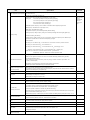
Table of Contents
Safety and Conformity ......................................................................................................... iv
Application ............................................................................................................................................................. iv
Installation .............................................................................................................................................................. iv
Wiring ..................................................................................................................................................................... v
Operation ............................................................................................................................................................... vi
Maintenance, Inspection and Part Replacements ................................................................................................. vii
Conformity with UL standards and CSA standards (cUL –listed for Canada) ....................................................... viii
1. Drive Model Identification, Installation and Wiring Practices ....................................... 1-1
1.1 Drive Models Constant Torque (CT) / Variable Torque (VT) HP Ratings ....................................................... 1-2
1.2 Installation and wiring practices ....................................................................................................................... 1-3
1.3 Precautions in running Inverters ...................................................................................................................... 1-11
1.4 Precautions in using special motors ................................................................................................................ 1-11
2. Mounting and Wiring the Inverter.................................................................................... 2-1
2.1 Operating Environment .................................................................................................................................... 2-1
2.2 Installing the Inverter ....................................................................................................................................... 2-1
2.3 Wiring ............................................................................................................................................................... 2-4
2.4 Mounting and Connecting the Keypad ............................................................................................................ 2-27
2.5 Input Power and Motor Connection ................................................................................................................. 2-28
3. Operation using the Keypad ............................................................................................ 3-1
3.1 LED Monitor, LCD Monitor, and Keys ............................................................................................................. 3-1
3.2 Overview of Operating Modes ......................................................................................................................... 3-3
3.3 Running Mode ................................................................................................................................................. 3-4
3.4 Programming Mode ......................................................................................................................................... 3-8
4. Function Codes / Parameters ......................................................................................... 4-1
4.1 Function Code Tables ..................................................................................................................................... 4-1
4.2 Details of Function Codes ............................................................................................................................... 4-25
5. Check Motor Rotation and Direction............................................................................... 5-1
6. Speed Reference Command Configuration .................................................................... 6-1
6.1 Reference from the Keypad ............................................................................................................................. 6-1
6.2 Reference from an Analog Signal (0-10V / 4-20mA) / Speed Pot ................................................................... 6-2
6.3 Reference from Serial Communication – RS485 ............................................................................................ 6-4
ii
7. Operation Method Configuration (Run / Stop) ............................................................... 7-1
7.1 Run / Stop from the Keypad ............................................................................................................................ 7-1
7.2 Run / Stop from External Switch / Contact or Pushbutton .............................................................................. 7-2
7.3 Run / Stop from Serial Communication – RS485 ............................................................................................ 7-4
8. Motor and Application Specific Settings ........................................................................ 8-1
8.1 Set Motor Nameplate Data .............................................................................................................................. 8-1
8.2 Acceleration and Deceleration Time................................................................................................................ 8-2
8.3 Torque Boost Setting ....................................................................................................................................... 8-3
8.3 Load Selection / Auto Torque Boost / Auto Energy Saving Operation ............................................................ 8-4
8.4 Reset EQ7 back to Factory Default ................................................................................................................. 8-6
9. Using PID Control for Constant Flow / Pressure Applications ..................................... 9-1
9.1 What is PID Control ......................................................................................................................................... 9-1
9.2 Connect Transducer Feedback Signal ........................................................................................................... 9-2
9.3 Setpoint Scaling / Transducer Feedback Scaling ............................................................................................ 9-4
10. Troubleshooting ............................................................................................................. 10-1
10.1 Protective Functions ...................................................................................................................................... 10-1
10.2 Before Proceeding with Troubleshooting ..................................................................................................... 10-2
10.3 If Neither an Alarm Nor “Light Alarm” Indication(
) Appears on the LED Monitor .................................. 10-5
10.4 If an Alarm Code Appears on the LED Monitor ............................................................................................. 10-12
10.5 If the “Light Alarm” Indication (
) Appears on the LED Monitor .............................................................. 10-25
10.6 If an Abnormal Pattern Appears on the LED Monitor .................................................................................... 10-26
10.7 If the inverter is running on Single-Phase Power .......................................................................................... 10-27
11. Specifications ................................................................................................................. 11-1
11.1 Drive Ratings ................................................................................................................................................. 11-1
11.2 Common Specifications ................................................................................................................................. 11-7
11.3 External Dimensions, Drive, Panel Cutting, DCR, Keypad ........................................................................... 11-12
iii
Application
• The EQ7 drive is designed to drive a three-phase induction motor. Do not use it for single-phase
motors or for other purposes.
Fire or an accident could occur.
• The EQ7 drive may not be used for a life-support system or other purposes directly related to the
human safety.
• Though the EQ7 drive is manufactured under strict quality control, install safety devices for
applications where serious accidents or property damages are foreseen in relation to the failure of
it.
An accident could occur.
Installation
• Install the inverter on a base made of metal or other non-flammable material.
Otherwise, a fire could occur.
• Do not place flammable object nearby.
Doing so could cause fire.
• Inverters with a capacity of 50 HP or above, whose protective structure is IP00 (Open Chassis),
involve a possibility that a human body may touch the live conductors of the main circuit terminal
block. Inverters to which an optional DC reactor is connected also involve the same. Install such
inverters in an inaccessible place.
Otherwise, electric shock or injuries could occur.
• Do not support the inverter by its front cover during transportation.
Doing so could cause a drop of the inverter and injuries.
• Prevent lint, paper fibers, sawdust, dust, metallic chips, or other foreign materials from getting into
the inverter or from accumulating on the heat sink.
• When changing the positions of the top and bottom mounting bases, use only the specified screws.
Otherwise, a fire or an accident might result.
• Do not install or operate an inverter that is damaged or lacking parts.
Doing so could cause fire, an accident or injuries.
iv
Wiring
• If no zero-phase current (earth leakage current) detective device such as a ground-fault relay is
installed in the upstream power supply line in order to avoid the entire power supply system's
shutdown undesirable to factory operation, install a residual-current-operated protective device
(RCD)/earth leakage circuit breaker (ELCB) individually to inverters to break the individual inverter
power supply lines only.
Otherwise, a fire could occur.
• When wiring the inverter to the power source, insert a recommended molded case circuit breaker
(MCCB) or residual-current-operated protective device (RCD)/earth leakage circuit breaker (ELCB)
(with overcurrent protection) in the path of each pair of power lines to inverters. Use the
recommended devices within the recommended current capacity.
• Use wires of the specified size.
• Tighten terminals with specified torque.
Otherwise, a fire could occur.
• When there is more than one combination of an inverter and motor, do not use a multi-conductor
cable for the purpose of running the leads together.
• Do not connect a surge absorber to the inverter's output (secondary) circuit.
Doing so could cause a fire.
• Be sure to connect an optional DC reactor (DCR) when the capacity of the power supply
transformer exceeds 500 kVA and is 10 times or more the inverter rated capacity.
Otherwise, a fire could occur.
• Ground the inverter in compliance with the national or local electric code.
• Be sure to ground the inverter's grounding terminals G.
Otherwise, an electric shock or a fire could occur.
• Qualified electricians should carry out wiring.
• Be sure to perform wiring after turning the power OFF.
Otherwise, an electric shock could occur.
• Be sure to perform wiring after installing the inverter unit.
Otherwise, an electric shock or injuries could occur.
• Ensure that the number of input phases and the rated voltage of the product match the number of
phases and the voltage of the AC power supply to which the product is to be connected.
Otherwise, a fire or an accident could occur.
• Do not connect the power supply wires to output terminals (U, V, and W).
• When connecting a DC braking resistor (DBR), never connect it to terminals other than terminals
P(+) and DB.
Doing so could cause fire or an accident.
• In general, the insulation of the control signal wires are not specifically designed to withstand a high
voltage (i.e., reinforced insulation is not applied). Therefore, if a control signal wire comes into direct
contact with a live conductor of the main circuit, the insulation may break down, which would
expose the signal wire to the high voltage of the main circuit. Make sure that the control signal wires
will not come into contact with live conductors of the main circuit.
Doing so could cause an accident or an electric shock.
v
• Before changing the switches or touching the control circuit terminal symbol plate, turn OFF the
power and wait at least five minutes for inverters of 40 HP or below, or at least ten minutes
for inverters of 50 HP or above. Make sure that the LED monitor and charging lamp are turned
OFF. Further, make sure, using a multimeter or a similar instrument, that the DC link bus voltage
between the terminals P(+) and N(-) has dropped to the safe level (+25 VDC or below).
Otherwise, an electric shock could occur.
• The inverter, motor and wiring generate electric noise. This may cause the malfunction of nearby
sensors and devices. To prevent malfunctioning, implement noise control measures.
Otherwise an accident could occur.
Operation
• Be sure to mount the front cover before turning the power ON. Do not remove the cover when the
inverter power is ON.
Otherwise, an electric shock could occur.
• Do not operate switches with wet hands.
Doing so could cause electric shock.
• If the auto-reset function has been selected, the inverter may automatically restart and drive the
motor depending on the cause of tripping. Design the machinery or equipment so that human safety
is ensured at the time of restarting.
Otherwise, an accident could occur.
• If the stall prevention function (current limiter), automatic deceleration (anti-regenerative control), or
overload prevention control has been selected, the inverter may operate with
acceleration/deceleration or frequency different from the commanded ones. Design the machine so
that safety is ensured even in such cases.
• If any of the protective functions have been activated, first remove the cause. Then, after checking
that the all run commands are set to OFF, release the alarm. If the alarm is released while any run
commands are set to ON, the inverter may supply the power to the motor, running the motor.
Otherwise, an accident could occur.
• If you enable the "Restart mode after momentary power failure" (Function code F14 = 3 to 5), then
the inverter automatically restarts running the motor when the power is recovered.
Design the machinery or equipment so that human safety is ensured after restarting.
• If the user configures the function codes wrongly without completely understanding this Instruction
Manual and the EQ7 DRIVE User's Manual, the motor may rotate with a torque or at a speed not
permitted for the machine.
An accident or injuries could occur.
• Even if the inverter has interrupted power to the motor, if the voltage is applied to the main circuit
input terminals L1/R, L2/S and L3/T, voltage may be output to inverter output terminals U, V, and W.
• Even if the run command is set to OFF, voltage is output to inverter output terminals U, V, and W if
the servo-lock command is ON.
• Even if the motor is stopped due to DC braking or preliminary excitation, voltage is output to inverter
output terminals U, V, and W.
An electric shock may occur.
• The inverter can easily accept high-speed operation. When changing the speed setting, carefully
check the specifications of motors or equipment beforehand.
Otherwise, injuries could occur.
vi
• Do not touch the heat sink and braking resistor because they become very hot.
Doing so could cause burns.
• The DC brake function of the inverter does not provide any holding mechanism.
Injuries could occur.
• Ensure safety before modifying the function code settings.
Run commands (e.g., "Run forward" FWD), stop commands (e.g., "Coast to a stop" BX), and
frequency change commands can be assigned to digital input terminals. Depending upon the
assignment states of those terminals, modifying the function code setting may cause a sudden
motor start or an abrupt change in speed.
• When the inverter is controlled with the digital input signals, switching run or frequency command
sources with the related terminal commands (e.g., SS1, SS2, SS4, SS8, Hz2/Hz1, Hz/PID, IVS, and
LE) may cause a sudden motor start or an abrupt change in speed.
• Ensure safety before modifying customizable logic related function code settings (U codes and
related function codes) or turning ON the "Cancel customizable logic" terminal command CLC.
Depending upon the settings, such modification or cancellation of the customizable logic may
change the operation sequence to cause a sudden motor start or an unexpected motor operation.
An accident or injuries could occur.
Maintenance, inspection and parts replacement
• Before proceeding to the maintenance/inspection jobs, turn OFF the power and wait at least five
minutes for inverters of 40 HP or below, or at least ten minutes for inverters of 50 HP or
above. Make sure that the LED monitor and charging lamp are turned OFF. Further, make sure,
using a multimeter or a similar instrument, that the DC link bus voltage between the terminals P(+)
and N(-) has dropped to the safe level (+25 VDC or below).
Otherwise, an electric shock could occur.
• Maintenance, inspection, and parts replacement should be made only by qualified persons.
• Take off the watch, rings and other metallic objects before starting work.
• Use insulated tools.
Otherwise, an electric shock or injuries could occur.
• Never modify the inverter.
Doing so could cause an electric shock or injuries.
Disposal
• Treat the inverter as an industrial waste when disposing of it.
Otherwise injuries could occur.
GENERAL PRECAUTIONS
Drawings in this manual may be illustrated without covers or safety shields for explanation of detail
parts. Restore the covers and shields in the original state and observe the description in the manual
before starting operation.
vii
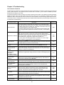
Conformity with UL standards and CSA standards (cUL-listed for Canada)
UL/cUL-listed inverters are subject to the regulations set forth by the UL standards and CSA standards (cULlisted for Canada) by installation within precautions listed below.
1. Solid state motor overload protection (motor protection by electronic thermal overload relay) is provided in each
model.
Use function codes F10 to F12 to set the protection level.
2. Use Cu wire only.
3. Use Class 1 wire only for control circuits.
4. Short circuit rating
"Suitable For Use On A Circuit Of Delivering Not More Than 100,000 rms Symmetrical Amperes, 240 Volts
Maximum for 230 V class input 40 HP or below, 230 Volts maximum for 230 V class input 50 HP or above
when protected by Class J Fuses or a Circuit Breaker having an interrupting rating not less than 100,000 rms
Symmetrical Amperes, 240 Volts Maximum." Models FRN; rated for 230 V class input.
"Suitable For Use On A Circuit Of Delivering Not More Than 100,000 rms Symmetrical Amperes, 480 Volts
Maximum when protected by Class J Fuses or a Circuit Breaker having an interrupting rating not less than
100,000 rms Symmetrical Amperes, 480 Volts Maximum." Models FRN; rated for 460 V class input.
"Integral solid state short circuit protection does not provide branch circuit protection. Branch circuit protection
must be provided in accordance with the National Electrical Code and any additional local codes."
5. Field wiring connections must be made by a UL Listed and CSA Certified closed-loop terminal connector sized
for the wire gauge involved. Connector must be fixed using the crimp tool specified by the connector
manufacturer.
6. All circuits with terminals L1/R, L2/S, L3/T, R0, T0, R1, T1 must have a common disconnect and be connected
to the same pole of the disconnect if the terminals are connected to the power supply.
7. When using the inverter as a UL Enclosed Type (UL TYPE1), purchase Type 1 kit (option) and mount it on the
inverter as instructed.
viii
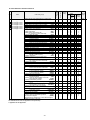
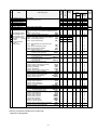
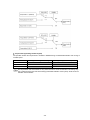
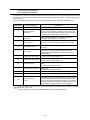
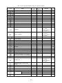
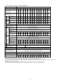
Conformity with UL standards and CSA standards (cUL-listed for Canada) (continued)
EQ7-2010-C
10
5
EQ7-2015-C
15
7.5
EQ7-2020-C
20
10
EQ7-2025-C
230 V
25
EQ7-2030-C
30
15
EQ7-2040-C
40
20
EQ7-2050-C
50
25
EQ7-2060-C
60
75
30
EQ7-2075-C
EQ7-2100-C
100
EQ7-2125-C
125
40
EQ7-2150-C
150
50
CT
VT
75 75 30.9
CT
(3.5)
VT
100 100
CT
VT
150 125
CT
*1
8
(8.4)
*2
*3
6
(13.3)
14
(2.1)
12
(3.3)
12
(3.3)
-
8
(8.4)
-
*1
*2
*3
-
4
(21.2)
VT
175 150
CT
51.3
(5.8)
VT
200 175
CT
10.6
(1.2)
VT
250 200
CT
119.4
(13.5)
VT
350 250
CT
VT
400 300
CT
238.9
(27)
VT
450
CT
350
10.6
VT
500
(1.2)
CT
VT
600 400 424.7
CT
(48)
VT 700 500
3
(26.7)
1
3
(42.4) (26.7)
-
2
(33.6)
4
(21.2)
3
4
(26.7) (21.2)
-
4/0
(107.2)
2/0×2
(67.4×2)
-
2
3
(33.6) (26.7)
2
(33.6)
1
(42.4)
1/0
(53.5)
2/0
(67.4)
3/0
(85)
6
(13.3)
-
*2
*3
-
4/0
(107.2)
3/0×2
(85×2)
3/0×2
(85×2)
4/0×2
(107.2×2
)
300×2
(152×2)
4/0×2
(107.2×2
)
300×2
(152×2)
14
(2.1)
*1
*2
-
*2
*3
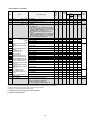
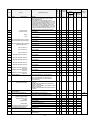
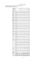
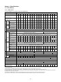
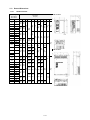
Note 1: Control circuit terminals Tightening torque: 6.1 lb-in (0.7 Nm), Recommended wire size: AWG 19 or 18 (0.65 to 0.82 mm2)
*1 No terminal end treatment is required for connection.
*2 Use 75C (167F) Cu (Copper) wire only.
*3 The wire size of UL Open Type and Enclosed Type are common. Please contact us if UL Open Type exclusive wire is necessary.
ix
Aux. fan power supply
10
(5.3)
Aux. control power
supply
10
(5.3)
-
14
(2.1)
Remarks
50
14
(2.1)
75C (167F)
Cu wire
60
EQ7-2007-C
14
(2.1)
U, V, W
60C (140F)
Cu wire
3
7.5
L1/R, L2/S, L3/T
Remarks
40
-
Main terminal
75C (167F)
Cu wire
5
Aux. Fan power supply
EQ7-2005-C
5 10.6
10 (1.2)
15
20 15.9
(1.8)
30
Aux. control power
supply
10
15
20
CT/
VT 30
Main terminal
EQ7-20P5-C
EQ7-2001-C
EQ7-2002-C
EQ7-2003-C
Wire size2
AWG (mm )
60C (140F)
Cu wire
0.25
0.5
1
1.5
Circuit breaker trip size (A)
Inverter type
Three- Singlephase phase
0.5
1
2
3
Class J fuse size (A)
Nominal
applied motor
(HP)
Required
torque
lb-in (Nm)
CT/VT mode
Power supply voltage
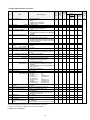
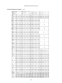
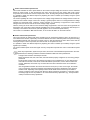
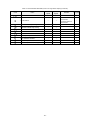
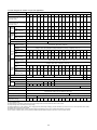
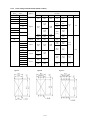
8. Install UL certified fuses or circuit breaker between the power supply and the inverter, referring to the table below.
14
(2.1)
EQ7-4010-C
10
5
EQ7-4015-C
15
7.5
EQ7-4020-C
20
25
10
EQ7-4025-C
EQ7-4030-C
30
15
EQ7-4040-C
460 V
40
20
EQ7-4050-C
50
25
EQ7-4060-C
60
30
EQ7-4075-C
75
EQ7-4100-C
100
40
CT
VT
CT
VT
CT
VT
CT
VT
CT
VT
CT
VT
CT
VT
CT
VT
CT
VT
CT
VT
30
40
40
60
50
70
60
90
75
30.9
(3.5)
-
-
*1
10
(5.3)
12
(3.3)
*2
*3
-
8
(8.4)
-
51.3
100 100 (5.8)
6
(13.3)
4
(21.2)
125
125
6
(13.3)
6
(13.3)
-
2
3
(33.6) (26.7)
10.6
(1.2)
1/0
(53.5)
250
*2
*3
10
(5.3)
6
(13.3)
14
(2.1)
*1
*2
2
(33.6)
1/0
(53.5)
-
175
*1
4
(21.2)
2
(33.6)
2
(33.6)
200
-
8
(8.4)
3
4
(26.7) (21.2)
200 150 119.4
(13.5)
Aux. fan power supply
14
(2.1)
-
12
(3.3)
175
Aux. control power supply
14
(2.1)
Remarks
14
(2.1)
Remarks
14
(2.1)
U, V, W
75C (167F)
Cu wire
30
Aux. Fan power supply
-
10
15.9
15
(1.8)
20
5
L1/R, L2/S, L3/T
60C (140F)
Cu wire
3
CT/
VT
10.6
(1.2)
3
6
10
15
20
Main terminal
75C (167F)
Cu wire
7.5
EQ7-40P5-C
EQ7-4001-C
EQ7-4002-C
EQ7-4003-C
EQ7-4005-C
EQ7-4007-C
Wire size
AWG (mm2)
60C (140F)
Cu wire
0.25
0.5
1
1.5
Aux. control power supply
0.5
1
2
3
5
Required
torque
lb-in (Nm)
Main terminal
Three- Singlephase phase
Circuit breaker trip size (A)
Inverter type
Class J fuse size (A)
Nominal applied
motor
(HP)
CT/VT mode
Power supply voltage
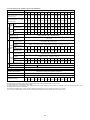
Conformity with UL standards and CSA standards (cUL-listed for Canada) (continued)
-
CT
2/0
(67.4)
EQ7-4125-C
125
VT
50
EQ7-4150-C
300 200
238.9
CT/VT 350 250 (27)
-
150
200
250
60
EQ7-4200-C
CT/VT 400 300
EQ7-4250-C
CT/VT 500 350
EQ7-4300-C
CT/VT 600
75
300
100
350
10.6
(1.2)
EQ7-4350-C
EQ7-4450-C
CT/VT 700
CT
500
424.7
(48)
700
1/0×2
(53.5×2
)
4/0
(107.2)
*2
*3
-
1/0×2
(53.5×2)
2/0×2
(67.4×2)
3/0×2
(85×2)
3/0×2
(85×2)
4/0×2
(107.2×
2)
250×2
(127×2)
250×2
(127×2)
300×2
(152×2)
*2
*3
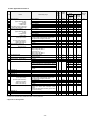
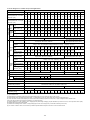
Note 1: Control circuit terminals Tightening torque: 6.1 lb-in (0.7 Nm), Recommended wire size: AWG 19 or 18 (0.65 to 0.82 mm2)
*1 No terminal end treatment is required for connection.
*2 Use 75C (167F) Cu (Copper) wire only.
*3 The wire size of UL Open Type and Enclosed Type are common. Please contact us if UL Open Type exclusive wire is necessary.
x
14
(2.1)
*1
*2
350
-
VT
600
125
400
450
-
460 V
500
600
700
EQ7-4500-C
CT
EQ7-4600-C
EQ7-4500-C
EQ7-4600-C
EQ7-4700-C
EQ7-4600-C
EQ7-4700-C
EQ7-4800-C
EQ7-4700-C
CT
VT
CT
CT
VT
CT
CT
VT
CT
VT
CT
VT
CT
1000
150
150
200
200
-
800
250
900
300
1000
400
EQ7-4800-C
EQ7-4900-C
EQ7-41000-C
800
424.7 10.6 10.6
(48) (1.2) (1.2)
1200
1200
350×2
(177×2)
400×2
(203×2)
300×2
(152×2)
*2
*3
300×2
(152×2)
350×2
(177×2)
400×2
(203×2)
400×2
(203×2)
-
500×2
(253×2)
*2
*4
*2
*3
500×2
(253×2)
600×2
(304×2)
600×2
(304×2)
1600
350×3
(177×3)
400×3
(203×3)
2000 1400
500×3
(253×3)
600×3
(304×3)
VT 2200 1600
600×3
(304×3)
500×4
(253×4)
1400
Remarks
75C (167F)
Cu wire
60C (140F)
Cu wire
U, V, W
Remarks
300×2
(152×2)
400×2
(203×2)
250×2
(127×2)
EQ7-4450-C
450
75C (167F)
Cu wire
L1/R, L2/S, L3/T
14 14
(2.1) (2.1)
*1 *1
*2 *2 *2
*4
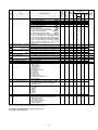
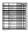
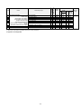
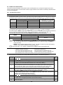
Note: Control circuit terminals Tightening torque: 6.1 lb-in (0.7 Nm), Recommended wire size: AWG 19 or 18 (0.65 to 0.82 mm2)
*1 No terminal end treatment is required for connection.
*2 Use 75C (167F) Cu (Copper) wire only.
*3 The wire size of UL Open Type and Enclosed Type are common. Please contact us if UL Open Type exclusive wire is necessary.
*4 It is showing the wire size for UL Open Type.
See additional material INR-SI47-1365-JE for UL Enclosed Type (Pack with TYPE1 kit).
xi
Aux. fan power supply
Main terminal
Aux. control power supply
Wire size
AWG (mm2)
60C (140F)
Cu wire
Aux. Fan power supply
800
Aux. control power supply
CT
Required
torque lb-in
(Nm)
Main terminal
Three- Singlephase phase
Circuit breaker trip size (A)
Inverter type
Class J fuse size (A)
Nominal applied
motor
HP
CT//VT mode
Power supply voltage
Conformity with UL standards and CSA standards (cUL-listed for Canada) (continued)
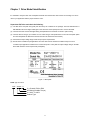
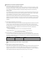
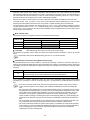
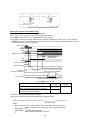
Chapter 1 Drive Model Identification
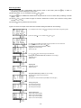
It is essential to verify the EQ7 drive nameplate and make sure that the EQ7 drive has the correct rating so it can be
used in your application with the proper sized AC motor.
Unpack the EQ7 drive and check the following:
(1) The EQ7 drive and quick start guide (this document) are contained in the package. The EQ7 DRIVE-2100-C /
EQ7 DRIVE-4100-C and higher rated types come with a DC reactor (DCR). Be sure to connect the DCR.
(2) The EQ7 drive has not been damaged during transportation there should be no dents or parts missing.
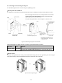
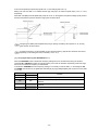
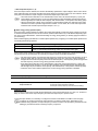
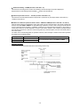
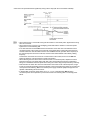
(3) The EQ7 drive is the type you ordered. You can check the type and specifications on the main nameplate. (Main
and sub nameplates are attached to the EQ7 drive and are located as shown below.)
(4) Check that the input voltage range meets the input power requirements.
(5) Ensure that for variable torque applications the motor rated current matches the variable torque FLA or for
constant torque applications it matches the constant torque FLA. Verify that the output voltage rating on the EQ7
drive label meets the motor requirements (nameplate).
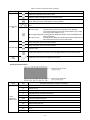
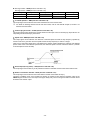
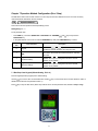
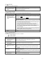
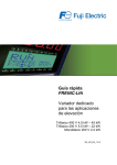
Figure 1.1 Nameplate
TYPE: Type of inverter
EQ7 – X XXX - X
C = Chassis; IP20 or IP00
HP Rating (Variable Torque)
2 = 230V, 4 = 460V
Product Type
1-1
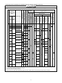
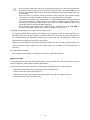
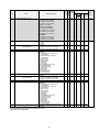
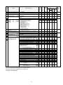
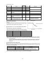
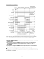
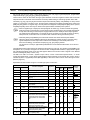
1.1 Drive Models Constant Torque (CT) / Variable Torque (VT) HP Ratings
Voltage
230V
460V
EQ7 DRIVE
Variable Torque HP
Constant Torque HP
Frame /
Enclosure
EQ7-20P5-C
EQ7-2001-C
EQ7-2002-C
EQ7-2003-C
EQ7-2005-C
EQ7-2007-C
EQ7-2010-C
EQ7-2015-C
EQ7-2020-C
EQ7-2025-C
EQ7-2030-C
EQ7-2040-C
EQ7-2050-C
EQ7-2060-C
EQ7-2075-C
EQ7-2100-C
EQ7-2125-C
EQ7-2150-C
EQ7-40P5-C
EQ7-4001-C
EQ7-4002-C
EQ7-4003-C
EQ7-4005-C
EQ7-4007-C
EQ7-4010-C
EQ7-4015-C
EQ7-4020-C
EQ7-4025-C
EQ7-4030-C
EQ7-4040-C
EQ7-4050-C
EQ7-4060-C
EQ7-4075-C
EQ7-4100-C
EQ7-4125-C
EQ7-4150-C
EQ7-4200-C
EQ7-4250-C
EQ7-4300-C
EQ7-4350-C
EQ7-4450-C
EQ7-4500-C
EQ7-4600-C
EQ7-4700-C
EQ7-4800-C
EQ7-4900-C
EQ7-41000-C
0.5
1
2
3
5
7.5
10
15
20
25
30
40
50
60
75
100
125
150
0.5
1
2
3
5
7.5
10
15
20
25
30
40
50
60
75
100
125
150
200
250
300
350
400/450
500
600
700
800
900
1000
0.5
1
2
3
5
7.5
7.5
10
15
20
25
30
40
50
60
75
100
125
0.5
1
2
3
5
7.5
7.5
10
15
20
25
30
40
50
60
75
100
125/150*
200*
250*
300*
350*
350
400/450*
500*
600*
700*
800
900
Plastic
Plastic
Plastic
Plastic
Plastic
Plastic
Plastic
Plastic
Plastic
Plastic
Plastic
Plastic
Sheet Metal
Sheet Metal
Sheet Metal
Sheet Metal
Sheet Metal
Sheet Metal
Plastic
Plastic
Plastic
Plastic
Plastic
Plastic
Plastic
Plastic
Plastic
Plastic
Plastic
Plastic
Sheet Metal
Sheet Metal
Sheet Metal
Sheet Metal
Sheet Metal
Sheet Metal
Sheet Metal
Sheet Metal
Sheet Metal
Sheet Metal
Sheet Metal
Sheet Metal
Sheet Metal
Sheet Metal
Sheet Metal
Sheet Metal
Sheet Metal
Table 1.1
This table shows the Variable Torque and Constant Torque ratings for all EQ7 drive models.
* The HP ratings marked with (*) are suitable for constant torque V/F Control. Refer to EQ7 Instruction Manual
chapter 11 for constant torque vector control HP ratings.
1-2
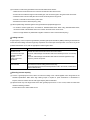
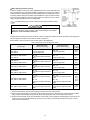
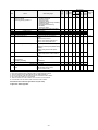
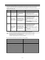
1.2 Installation and wiring practices
Mounting of the EQ7 drive is extremely important for accessibility as well as for the environment. Various EQ7 drive
models are available and the mounting dimensions (footprint) may be different. Install the EQ7 drive in an
environment that satisfies the requirements.
TECO-Westinghouse Motor Company strongly recommends installing inverters in a panel for safety reasons, in
particular, when installing the ones that have an enclosure rating of IP00.
When installing the EQ7 drive in a place out of the specified environmental requirements, it is necessary to derate the
inverter or consider the panel engineering design suitable for the special environment or the panel installation
location. For details consult your TECO-Westinghouse Motor Company representative. The special environments
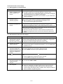
listed below require using the specially designed panel or considering the panel installation location.
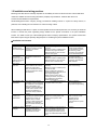
Installation environment
Environments
Possible problems
Sample measures
Applications
Highly concentrated
sulfurizing gas or
other corrosive gases
Corrosive gases cause parts
inside the inverter to corrode,
resulting in an inverter
malfunction.
A lot of conductive
dust or foreign
material (e.g., metal
powders or shavings,
carbon fibers, or
carbon dust)
A lot of fibrous or
paper dust
Entry of conductive dust into
the inverter causes a short
circuit.
Any of the following measures may be
necessary.
-Mount the inverter in a sealed panel
with IP6X or air-purge mechanism.
-Place the panel in a room free from
influence of the gases.
Any of the following measures may be
necessary.
-Mount the inverter in a sealed panel.
-Place the panel in a room free from
influence of the conductive dust.
Paper manufacturing, sewage
disposal, sludge treatment,
tire manufacturing, gypsum
manufacturing, metal
processing, and a particular
process in textile factories.
Wiredrawing machines, metal
processing, extruding
machines, printing presses,
combustors, and industrial
waste treatment.
Textile manufacturing and
paper manufacturing.
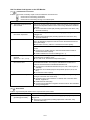
High humidity or dew
condensation
In an environment where a
humidifier is used or where the
air conditioner is not equipped
with a dehumidifier, high
humidity or dew condensation
results, which causes a shortcircuiting or malfunction of
electronic circuitry inside the
inverter.
If a large vibration or shock
exceeding the specified level is
applied to the inverter, for
example, due to a carrier
running on seam joints of rails
or blasting at a construction
site, the inverter structure gets
damaged.
Halogen compounds such as
methyl bromide used in
fumigation corrodes some
parts inside the inverter.
Any of the following measures may be
necessary.
-Mount the inverter in a sealed panel
that shuts out dust.
-Ensure a maintenance space for
periodical cleaning of the heat sink in
panel engineering design.
-Employ external cooling when
mounting the inverter in a panel for
easy maintenance and perform
periodical maintenance.
Put a heating module such
as a space heater in the panel.
-Insert shock-absorbing materials
between the mounting base of the
inverter and the panel for safe
mounting.
Installation of an inverter
panel on a carrier or selfpropelled machine.
Ventilating fan at a
construction site or a press
machine.
-When exporting an inverter built in a
panel or equipment, pack them in a
previously fumigated wooden crate.
-When packing an inverter alone for
export, use a laminated veneer lumber
(LVL).
Exporting.
Vibration or shock
exceeding the
specified level
Fumigation for export
packaging
Fibrous or paper dust
accumulated on the heat sink
lowers the cooing effect.
Entry of dust into the inverter
causes the electronic circuitry
to malfunction.
Table 1.2: Installation environment
1-3
Outdoor installation.
Film manufacturing line,
pumps and food processing.
Storage environment
The storage environment in which the inverter is stored after purchase is different from the operation environment.
For details, refer to the EQ7 DRIVE User's Manual, Chapter 2.
Wiring precautions
(1) Route the wiring of the control circuit terminals as far from the wiring of the main circuit as possible. Otherwise
electric noise may cause malfunctions.
(2) Place the control circuit wires inside the inverter to keep them away from the live parts of the main circuit (such as
the terminal block of the main circuit).
(3) If more than one motor is to be connected to a single inverter, the wiring length should be the sum of the length of
the wires to the motors.
(4) Drive output terminals (U, V, W)
1) Connect these terminals to a 3-phase motor in the correct phase sequence. If the direction of motor rotation is
incorrect, exchange any two of the U, V, and W phases.
2) Do not connect a power factor correction capacitor or surge suppressor to the inverter output.
3) If the cable from the inverter to the motor is very long, a high-frequency current may be generated by stray
capacitance between the cables and result in an overcurrent trip of the inverter, an increase in leakage current,
or a reduction in current indication precision.
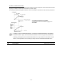
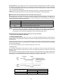
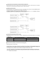
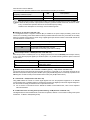
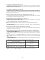
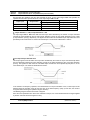
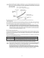
When a motor is driven by a PWM-type inverter, the motor terminals may be subject to surge voltage
generated by inverter element switching. If the motor cable (with 460 V series motors, in particular) is particularly
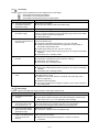
long, surge voltage will deteriorate motor insulation. To prevent this, use the following guidelines:
Inverter 7.5 HP and larger
Motor Insulation Level
460 VAC Input Voltage
230 VAC Input Voltage
1000 V
66 ft (20 m)
1312 ft (400 m)*
1300 V
328 ft (100 m)
1312 ft (400 m)*
1600 V
1312 ft (400 m)*
1312 ft (400 m)*
Inverter 5 HP and smaller
Motor Insulation Level
460 VAC Input Voltage
230 VAC Input Voltage
1000 V
66 ft (20 m)
328 ft (100 m)*
1300 V
165 ft (50 m)*
328 ft (100 m)*
1600 V
165 ft (50 m)*
328 ft (100 m)*
* For this case the cable length is determined by secondary effects and not voltage spiking.
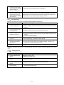
(5)
• When a motor protective thermal O/L relay is inserted between the inverter and the motor, the thermal
O/L relay may malfunction (particularly in the 460 V series), even when the cable length is 165 ft (50 m) or
less. To correct, insert a filter or reduce the carrier frequency. (Use function code F26 "Motor sound".)
• For the vector control mode, wiring length is 328 ft (100 m) or less.
When an output circuit filter is inserted in the secondary circuit or the wiring between the inverter and the
motor is long, a voltage loss occurs due to reactance of the filter or wiring so that the insufficient voltage may cause
output current oscillation or a lack of motor output torque. To avoid it, select the constant torque load by setting the
function code F37 (Load Selection/Auto Torque Boost/Auto Energy Saving Operation 1) to "1" and keep the inverter
output voltage at a higher level by configuring H50/H52 (Non-linear V/f Pattern, Frequency) and H51/H53 (Non-linear
V/f Pattern, Voltage).
1-4
Precautions for connection of peripheral equipment
(1) Phase-advancing capacitors for power factor correction
Do not mount a phase-advancing capacitor for power factor correction in the inverter's input (primary) or output
(secondary) circuit. Mounting it in the input (primary) circuit takes no effect. To correct the inverter power factor,
use an optional DC reactor (DCR). Mounting it in the output (secondary) circuit causes an overcurrent trip,
disabling operation.
An overvoltage trip that occurs when the inverter is stopped or running with a light load is assumed to be due to
surge current generated by open/close of phase-advancing capacitors in the power system. An optional DC/AC
reactor (DCR/ACR) is recommended as a measure to be taken at the inverter side.
Input current to an inverter contains a harmonic component that may affect other motors and phase-advancing
capacitors on the same power supply line. If the harmonic component causes any problems, connect an optional
DCR/ACR to the inverter. In some cases, it is necessary to insert a reactor in series with the phase-advancing
capacitors.
(2) Power supply lines (Application of a DC/AC reactor)
Use an optional DC reactor (DCR) when the capacity of the power supply transformer is 500 kVA or more and is
10 times or more the inverter rated capacity or when there are thyristor-driven loads. If no DCR is used, the
percentage-reactance of the power supply decreases, and harmonic components and their peak levels increase.
These factors may break rectifiers or capacitors in the converter section of the inverter, or decrease the
capacitance of the capacitors.
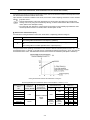
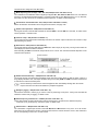
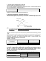
If the input voltage unbalance rate is 2% to 3%, use an optional AC reactor (ACR).
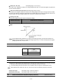
Voltage unbalance(%) =
Max voltage (V) - Min voltage (V)
× 67 (IEC 61800- 3)
Three - phase average voltage (V)
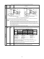
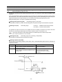
(3) DC reactor (DCR) for correcting the inverter input power factor (for suppressing harmonics)
To correct the inverter input power factor (to suppress harmonics), use an optional DCR. Using a DCR increases
the reactance of inverter’s power source so as to decrease harmonic components on the power source lines and
correct the power factor of the inverter.
DCR models
Input power factor
Remarks
DCR2/4-/A/B
Approx. 90% to 95%
The last letter identifies the capacitance.
DCR2/4-C
Approx. 86% to 90%
Exclusively designed for inverters of 50 HP or above.
For selecting DCR models, refer to Chapter 11 "SPECIFICATIONS."
(4) PWM converter for correcting the inverter input power factor
Using a PWM converter (High power-factor, regenerative PWM converter) corrects the inverter power factor up to
nearly 100%. When combining an inverter with a PWM converter, disable the main power down detection by
setting the function code H72 to "0." If the main power loss detection is enabled (H72 = 1 by factory default), the
inverter interprets the main power as being shut down, ignoring an entry of a run command.
1-5
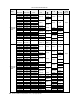
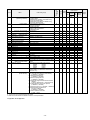
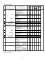
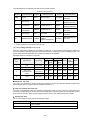
(5) Molded case circuit breaker (MCCB) or residual-current-operated protective device (RCD)/earth leakage circuit
breaker (ELCB)
Install a recommended MCCB or RCD/ELCB (with overcurrent protection) in the primary circuit of the inverter to
protect the wiring. Since using an MCCB or RCD/ELCB with a lager capacity than recommended ones breaks the
protective coordination of the power supply system, be sure to select recommended ones. Also select ones with
short-circuit breaking capacity suitable for the power source impedance.
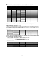
Molded Case Circuit Breaker (MCCB) and Residual-Current-Operated Protective Device (RCD)/Earth Leakage
Circuit Breaker (ELCB)
Nominal
applied
motor
Power
(HP)
supply
Inverter type
voltage Three
Singlephase
phase
0.5
0.25
EQ7-20P5-C
1
0.5
EQ7-2001-C
2
1
EQ7-2002-C
3
1.5
EQ7-2003-C
5
7.5
5
EQ7-2015-C
15
7.5
EQ7-2020-C
20
10
EQ7-2025-C
25
EQ7-2030-C
230 V
30
15
40
20
EQ7-2040-C
EQ7-2050-C
50
25
EQ7-2060-C
60
75
30
EQ7-2075-C
EQ7-2100-C
100
125
150
CT/VT
EQ7-2007-C
EQ7-2010-C
10
5
EQ7-2005-C
3
40
50
EQ7-2125-C
EQ7-2150-C
Nominal
applied
motor
Power
(HP)
supply
voltage Three
Singlephase
phase
Inverter type
5
0.5
0.25
EQ7-40P5-C
10
1
0.5
EQ7-4001-C
15
2
1
EQ7-4002-C
3
1.5
EQ7-4003-C
Rated current of
MCCB and
CT/VT RCD/ELCB (A)
mode
w/ DCR w/o
DCR
CT
VT
CT
VT
CT
VT
CT
10
20
30
5
30
50
7.5
40
75
10
VT
100
75
125
CT
VT
CT
VT
CT
VT
CT
VT
CT
VT
CT
VT
EQ7-4015-C
EQ7-4020-C
20
460 V
150
25
10
100
EQ7-4025-C
EQ7-4030-C
175
30
15
EQ7-4040-C
150
200
40
20
EQ7-4050-C
175
250
50
25
EQ7-4060-C
200
300
60
30
250
350
EQ7-4075-C
75
EQ7-4100-C
350
400
100
--
350
1-6
10
40
EQ7-4125-C
CT
VT
CT
VT
CT
VT
CT
VT
CT
VT
CT
VT
CT
VT
CT
VT
CT
20
30
20
40
30
50
40
60
40
75
50
100
75
125
100
150
CT
VT
15
15
VT
CT
5
10
CT/VT
EQ7-4007-C
15
7.5
CT
VT
3
5
50
5
EQ7-4005-C
EQ7-4010-C
VT
CT
20
Rated current of
MCCB and
CT/VT RCD/ELCB (A)
mode
w/o
w/ DCR DCR
125
200
175
--
Molded Case Circuit Breaker (MCCB) and Residual-
Leakage Circuit Breaker (ELCB)
Current-Operated Protective Device (RCD)/Earth
Nominal
applied
motor
Power
(HP)
supply
Inverter type
voltage Three
Singlephase
phase
125
EQ7-4125-C
50
EQ7-4150-C
150
200
60
EQ7-4200-C
EQ7-4250-C
250
460 V
75
Nominal
applied
Power
motor
supply
(HP)
voltage
Three- Singlephase phase
Rated current of
MCCB and
CT/VT RCD/ELCB (A)
mode
w/ DCR w/o
DCR
VT
CT
CT/VT
CT
CT/VT
CT
CT/VT
500
200
250
600
300
460 V
350
EQ7-4300-C CT/VT
300
500
100
800
--
450
400
-
EQ7-4350-C CT/VT
EQ7-4450-C
-
-
150
EQ7-4500-C
VT
-
EQ7-4600-C
CT
150
EQ7-4700-C
CT
200
EQ7-4600-C
VT
-
EQ7-4700-C
CT
EQ7-4800-C
CT
EQ7-4700-C
VT
200
-
EQ7-4800-C
250
900
1000
600
300
400
EQ7-41000-C
800
1200
--
CT
VT
CT
VT
1400
CT
VT
1600
VT
125
450
CT
150
EQ7-4900-C
350
350
700
Inverter type
Rated current of
MCCB and
CT/VT RCD/ELCB (A)
mode
w/ DCR w/o
DCR
EQ7-4500-C
CT
EQ7-4600-C
CT
800
If no zero-phase current (earth leakage current) detective device such as a ground-fault relay is installed in the
upstream power supply line in order to avoid the entire power supply system's shutdown undesirable to factory
operation, install a residual-current-operated protective device (RCD)/earth leakage circuit breaker (ELCB)
individually to inverters to break the individual inverter power supply lines only.
Otherwise, a fire could occur.
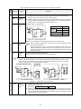
(6) Magnetic contactor (MC) in the inverter input (primary) circuit
Avoid frequent ON/OFF operation of the magnetic contactor (MC) in the input circuit; otherwise, the inverter failure
may result. If frequent start/stop of the motor is required, use FWD/REV terminal signals or the
/
keys on the
inverter's keypad.
The frequency of the MC's ON/OFF should not be more than once per 30 minutes. To assure 10-year or longer
service life of the inverter, it should not be more than once per hour.
1-7
• From the system's safety point of view, it is recommended to employ such a sequence that shuts down
the magnetic contactor (MC) in the inverter input circuit with an alarm output signal ALM issued on
inverter's programmable output terminals. The sequence minimizes the secondary damage even if the
inverter breaks.
When the sequence is employed, connecting the MC's primary power line to the inverter's auxiliary
control power input makes it possible to monitor the inverter's alarm status on the keypad.
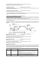
• The breakdown of a braking unit or misconnection of an external braking resistor may trigger that of the
inverter's internal parts (e.g., charging resistor). To avoid such a breakdown linkage, introduce an MC
and configure a sequence that shuts down the MC if a DC link voltage establishment signal is not
issued within three seconds after the MC is switched on.
For the braking transistor built-in type of inverters, assign a transistor error output signal DBAL on
inverter's programmable output terminals to switch off the MC in the input circuit.
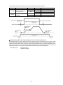
(7) Magnetic contactor (MC) in the inverter output (secondary) circuit
If a magnetic contactor (MC) is inserted in the inverter's output (secondary) circuit for switching the motor to a
commercial power or for any other purposes, it should be switched on and off when both the inverter and motor
are completely stopped. This prevents the contact point from getting rough due to a switching arc of the MC. The
MC should not be equipped with any main circuit surge killer.
Applying a commercial power to the inverter's output circuit breaks the inverter. To avoid it, interlock the MC on the
motor's commercial power line with the one in the inverter output circuit so that they are not switched ON at the
same time.
(8) Surge absorber/surge killer
Do not install any surge absorber or surge killer in the inverter's output (secondary) lines.
Noise reduction
If noise generated from the inverter affects other devices, or that generated from peripheral equipment causes the
inverter to malfunction, follow the basic measures outlined below.
(1) If noise generated from the inverter affects the other devices through power wires or grounding wires:
- Isolate the grounding terminals of the inverter from those of the other devices.
- Connect a noise filter to the inverter power wires.
- Isolate the power system of the other devices from that of the inverter with an insulated transformer.
- Decrease the inverter's carrier frequency (F26).
1-8
(2) If induction or radio noise generated from the inverter affects other devices:
- Isolate the main circuit wires from the control circuit wires and other device wires.
- Put the main circuit wires through a metal conduit pipe, and connect the pipe to the ground near the inverter.
- Install the inverter into the metal panel and connect the whole panel to the ground.
- Connect a noise filter to the inverter's power wires.
- Decrease the inverter's carrier frequency (F26).
(3) When implementing measures against noise generated from peripheral equipment:
- For inverter's control signal wires, use twisted or shielded-twisted wires. When using shielded-twisted wires,
connect the shield of the shielded wires to the common terminals of the control circuit.
- Connect a surge absorber in parallel with magnetic contactor's coils or other solenoids (if any).
Leakage current
A high frequency current component generated by insulated gate bipolar transistors (IGBTs) switching on/off inside the
inverter becomes leakage current through stray capacitance of inverter input and output wires or a motor. If any of the
problems listed below occurs, take an appropriate measure against them.
Problem
An earth leakage circuit
breaker* that is
connected to the input
(primary) side has
tripped.
*With overcurrent
protection
Measures
1) Decrease the carrier frequency.
2) Make the wires between the inverter and motor shorter.
3) Use an earth leakage circuit breaker with lower sensitivity than the one currently
used.
4) Use an earth leakage circuit breaker that features measures against the high
frequency current component.
An external thermal relay
was activated.
1) Decrease the carrier frequency.
2) Increase the current setting of the thermal relay.
3) Use the electronic thermal overload protection built in the inverter, instead of the
external thermal relay.
Selecting inverter capacity
(1) To drive a general-purpose motor, select an inverter according to the nominal applied motor rating listed in the
standard specifications table. When high starting torque is required or quick acceleration or deceleration is
required, select an inverter with one rank higher capacity than the standard.
(2) Special motors may have larger rated current than general-purpose ones. In such a case, select an inverter that
meets the following condition.
Inverter rated current > Motor rated current
1-9
1.3 Precautions in running inverters
Precautions for running inverters to drive motors or motor-driven machinery are described below.
Motor temperature
When an inverter is used to run a general-purpose motor, the motor temperature becomes higher than when it is
operated with a commercial power supply. In the low-speed range, the motor cooling effect will be weakened, so
decrease the output torque of the motor when running the inverter in the low-speed range.
Motor noise
When a general-purpose motor is driven by an inverter, the noise level is higher than that when it is driven by a
commercial power supply. To reduce noise, raise carrier frequency of the inverter. Operation at 60 Hz or higher can
also result in higher noise level.
Machine vibration
When an inverter-driven motor is mounted to a machine, resonance may be caused by the natural frequencies of the
motor-driven machinery. Driving a 2-pole motor at 60 Hz or higher may cause abnormal vibration. If it happens, do any
of the following:
- Consider the use of a rubber coupling or vibration-proof rubber.
- Use the inverter's jump frequency control feature to skip the resonance frequency zone(s).
- Use the vibration suppression related function codes that may be effective. For details, refer to the description of
H80 in Chapter 4 "FUNCTION CODES" of the user manual.
1.4 Precautions in using special motors
When using special motors, please read the following section:
Explosion-proof motors
When driving an explosion-proof motor with an inverter, use a combination of a motor and an inverter that has been
approved in advance.
Submersible motors and pumps
These motors have a larger rated current than general-purpose motors. Select an inverter with rated output current
that is greater than that of the motor. These motors differ from general-purpose motors in thermal characteristics.
Decrease the thermal time constant of the electronic thermal overload protection to match the motor rating.
Brake motors
For motors equipped with parallel-connected brakes, their power supply for braking must be supplied from the inverter
input (primary) circuit. If the power supply for braking is mistakenly connected to the inverter's output (secondary)
circuit, the brake may not work when the inverter output is shut down. Do not use inverters for driving motors
equipped with series-connected brakes.
Geared motors
If the power transmission mechanism uses an oil-lubricated gearbox or speed changer/reducer, then continuous
operation at low speed may cause poor lubrication. Avoid such operation.
Synchronous motors
It is necessary to take special measures suitable for this motor type. Contact your TECO-Westinghouse Motor
Company representative for details.
Single-phase motors
Single-phase motors are not suitable for inverter-driven variable speed operation.
1-10
High-speed motors
If the reference frequency is set to 120 Hz or higher to drive a high-speed motor, test-run the combination of the
inverter and motor beforehand to check it for the safe operation.
Precautions for use on single-phase power
An inverter is a device that converts alternating current of the input line to direct current via the ac-to-dc rectifier and
then converts it to alternating current via the dc-to-ac switching inverter circuit in order to output the required
alternating current. The EQ7 drive is designed to connect to the three-phase power and this manual stipulates the
specifications for the use on the three-phase power.
If the inverter designed for connection to three-phase power runs on single-phase power, ripples (voltage fluctuation)
on the DC link bus voltage rectified from the input power become larger than those in the inverter running on threephase power. The DC-voltage ripple affects the inverter output; that is, ripples could be superimposed on the output
voltage or current, making control hard.
Accordingly, the inverter may not work in full performance or function correctly. To use the EQ7 drive on single-phase
power, therefore, you need to take the following into account.
Output current
Select the inverter capacity to keep the output current within the specified level, referring to chapter 11. Output current
exceeding the limit extremely increases voltage ripples on the DC link bus, impeding normal operation or resulting in
an inverter breakdown.
Wiring
When connecting 230 V inverters of 60 HP or above or 460 V ones of 125 HP or above to single-phase power, use L1
and L3 phases since cooling fans and magnetic contactors inside the inverter are supplied with power via L1 and L3.
Using L2 does not work cooling fans or magnetic contactors, causing abnormal heat, in the worst case, resulting in an
inverter breakdown.
Connecting peripheral devices
For the specifications of circuit breakers and fuses to apply, refer to pages 1-6 and 1-7.
Configuring function codes
(1) Cancel the input phase loss protection of the protection/maintenance function with function code H98 (Bit 1 = 0).
This is because the inverter judges single-phase power as a phase loss.
(2) Limit the drive mode to the VT / CT-V mode (Function code F80 = 0 or 1).
(3) Do not use "Vector control without speed sensor" or torque control. (Function codes F42 5, H18 = 0)
(4) "V/f control with slip compensation inactive" is recommended (F42 = 0). Any other drive control calculates the
motor model using the motor parameters inside the inverter. As ripples on the DC link bus voltage become larger,
therefore, calculation causes some errors so that the inverter may not provide the desired performance. Consider
this problem before use. In particular, when using "Vector control with speed sensor" (F42 = 6), dancer control
(J01 = 3), or brake signals (J68, J69, J70, etc.), assure the operation and safety of those speed sensors.
1-11
Chapter 2 Mounting and Wiring the Inverter
2.1 Operating Environment
Install the inverter in an environment that satisfies the requirements listed in Table 2.1.
Table 2.1 Environmental Requirements
Item
Site location
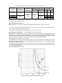
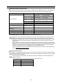
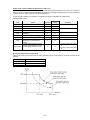
Table 2.2 Output Current Derating
Factor in Relation to Altitude
Specifications
Indoors
Altitude
Surrounding/ambient -10 to +50C (14 to 122F) (Note 1)
temperature
Relative humidity
5 to 95% (No condensation)
Atmosphere
The inverter must not be exposed to dust, direct sunlight,
corrosive gases, flammable gases, oil mist, vapor or water drops.
Pollution degree 2 (IEC60664-1) (Note 2)
The atmosphere can contain a small amount of salt.
(0.01 mg/cm2 or less per year)
The inverter must not be subjected to sudden changes in
temperature that will cause condensation to form.
Altitude
3300 ft (1000 m) max. (Note 3)
Atmospheric
pressure
86 to 106 kPa
Vibration
Inverters of
100 HP or below (230 V series)
125 HP or below (460 V series)
0.12 inch (3 mm)
(Max. amplitude)
2 to less than 9 Hz
9.8 m/s2 9 to less than 20 Hz
2 m/s2 20 to less than 55 Hz
1 m/s2 55 to less than 200 Hz
Inverters of
125 HP or above (230 V series)
150 HP or above (460 V series)
0.12 inch (3 mm)
(Max. amplitude)
2 to less than 9 Hz
2 m/s29 to less than 55 Hz
1 m/s255 to less than 200 Hz
2.2 Installing the Inverter
(1) Mounting base
Install the inverter on a base made of metal or other non-flammable material.
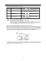
3300 ft (1000 m)
or lower
3300 to 4900 ft
(1000 to 1500 m)
4900 to 6600 ft
(1500 to 2000 m)
6600 to 8200 ft
(2000 to 2500 m)
8200 to 9800 ft
(2500 to 3000 m)
Output current
derating factor
1.00
0.97
0.95
0.91
0.88
(Note 1) When inverters (40 HP or
below) are mounted side-by-side without
any clearance between them, the
surrounding temperature should be within
the range from -10 to +40C (14 to 104F).
This specification also applies to the
inverters (40 HP) equipped with a NEMA1
kit.
(Note 2) Do not install the inverter in an
environment where it may be exposed to
lint, cotton waste or moist dust or dirt
which will clog the heat sink of the
inverter. If the inverter is to be used in
such an environment, install it in a
dustproof panel.
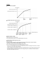
(Note 3) If you use the inverter in an
altitude above 3300 ft (1000 m), you
should apply an output current derating
factor as listed in Table 2.2.
Install the inverter on a base made of metal or other non-flammable material.
Otherwise, a fire could occur.
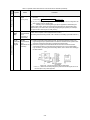
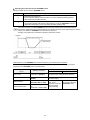
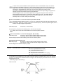
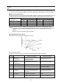
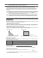
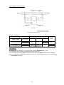
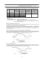
(2) Clearances
Ensure that the minimum clearances indicated in Figure 2.1 and Table 2.3 are
maintained at all times. When mounting the inverter in the panel of your system,
take extra care with ventilation inside the panel as the surrounding temperature
easily rises. Do not mount the inverter in a small panel with poor ventilation.
When mounting two or more inverters
When mounting two or more inverters in the same unit or panel, install them side
by side. When one must be mounted above the other, be sure to separate them
with a partition plate, or the like, so that any heat radiating from an inverter will not
affect the one/s above.
As long as the surrounding temperature is 40°C (104°F) or lower, inverters of 40
HP or below can be mounted side by side without any clearance between them.
Table 2.3 Clearances
Inverter capacity
A
0.5 to 2 HP
2.0 (50)
3 to 40 HP
0.39 (10)
B
3.9 (100)
50 to 450 HP
500 to 1000 HP
inch (mm)
C
0
3.9 (100)
2.0 (50)
5.9 (150)
C: Space required in front of the inverter unit
2-1
5.9 (150)
Figure 2.1 Mounting Direction and
Required Clearances
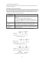
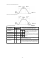
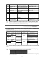
When employing external cooling
In external cooling, the heat sink, which dissipates about 70% of the total heat (total
loss) generated into air, is situated outside the equipment or the panel. The external
cooling, therefore, significantly reduces heat radiating inside the equipment or panel.
To employ external cooling for inverters (except DCR built-in type) of 40 HP or below,
use the mounting adapter for external cooling (option); for those of 50 HP or above,
simply change the positions of the mounting bases.
The DCR built-in type of 40 HP or below cannot employ external cooling.
Figure 2.2 External Cooling
Prevent lint, paper fibers, sawdust, dust, metallic chips, or other foreign
materials from getting into the inverter or from accumulating on the heat sink.
Otherwise, a fire or accident could occur.
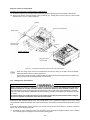
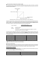
To utilize external cooling for inverters of 50 HP or above, change the positions of the top and bottom mounting bases
from the edge to the center of the inverter as shown in Figure 2.3.
Screws differ in size and count for each inverter. Refer to the table below.
Table 2.4 Screw Size, Count and Tightening Torque
Inverter type
Base fixing screw
(Screw size and q'ty)
Case fixing screw
(Screw size and q'ty)
Tightening
torque
lb-in (Nm)
EQ7-2050-C /EQ7-2060-C
EQ7-4050-C
EQ7-4100-C
M6 20
5 pcs for upper side,
3 pcs for lower side
M6 20
2 pcs for upper side
51.3
(5.8)
EQ7-2075-C / EQ7-4100-C
EQ7-4125-C
M6 20
3 pcs each for upper and lower
sides
M6 12
3 pcs for upper side
51.3
(5.8)
EQ7-2125-C
EQ7-4150-C / EQ7-4200-C
M5 12
7 pcs each for upper and lower
sides
M5 12
7 pcs for upper side
31.0
(3.5)
EQ7-4250-C / EQ7-4300-C
M5 16
7 pcs each for upper and lower
sides
M5 16
7 pcs for upper side
31.0
(3.5)
EQ7-2150-C
EQ7-4350-C / EQ7-4450-C
M5 16
8 pcs each for upper and lower
sides
M5 16
8 pcs for upper side
31.0
(3.5)
EQ7-4500-C / EQ7-4600-C
EQ7-4700-C / EQ7-4800-C
M5 16
2 pcs each for upper and lower
sides
M6 20
6 pcs each for upper and lower
sides
M5 16
2 pcs each for upper and lower
sides
M6 20
6 pcs each for upper and lower
sides
31.0
(3.5)
51.3
(5.8)
EQ7-4900-C / EQ7-41000-C
M8 20
8 pcs each for upper and lower
sides
M8 20
8 pcs each for upper and lower
sides
119
(13.5)
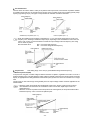
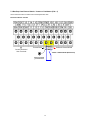
1) Remove all base fixing screws and case fixing screws from the top of the inverter.
2) Move the top mounting base to the center of the inverter and secure it to the case fixing screw holes with the base
fixing screws. (After changing the position of the top mounting base, some screws may be left unused.)
3) Remove the base fixing screws from the bottom of the inverter, move the bottom mounting base to the center of the
inverter, and secure it with the base fixing screws, just as in step 2). (Inverters of 450 HP or below have no case
fixing screws on the bottom.)
2-2
Figure 2.3 Changing the Positions of the Top and Bottom Mounting Bases
When changing the positions of the top and bottom mounting bases, use only the specified screws.
Otherwise, a fire or accident could occur.
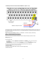
(3) Mounting notes
The EQ7-2007-C / EQ7-4007-C through EQ7-2040-C / EQ7-4040-C should be mounted with four screws or bolts using
screw holes A or B shown below. Note that, at each of the top and bottom of the inverter, the two screws or bolts should
be located in a bilaterally symmetrical position.
2-3
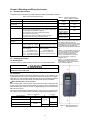
2.3 Wiring
Follow the procedure below. (In the following description, the inverter has already been installed.)
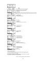
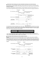
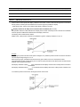
2.3.1 Removing and mounting the front cover and the wiring guide
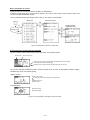
(1) For inverters of 40 HP or below
First loosen the front cover fixing screw, slide the cover downward holding both sides, tilt it forward, and then pull it
upward, as shown below.
While pressing the wiring guide upward, pull it out and forward.
After carrying out wiring (see Sections 2.3.2 through 2.3.6), put the wiring guide and the front cover back into place
in the reverse order of removal.
Figure 2.4 Removing the Front Cover and the Wiring Guide (e.g EQ7-4020-C)
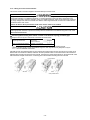
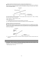
(2) For inverters of 50 to 1000 HP
Loosen the four front cover fixing screws, hold the cover with both hands, slide it upward slightly, and pull it forward,
as shown below.
After carrying out wiring (see Sections 2.3.2 through 2.3.6), align the screw holes provided in the front cover with the
screws on the inverter case, and then put the front cover back into place in the reverse order of removal.
To expose the control printed circuit board (control PCB), open the keypad enclosure.
Tightening torque: 15.9 lb-in (1.8 Nm) (M4)
31.0 lb-in (3.5 Nm) (M5)
Figure 2.5 Removing the Front Cover (e.g. EQ7-4050-C)
2-4
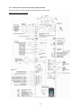
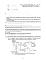
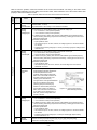
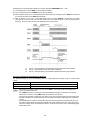
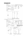
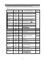
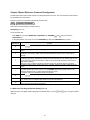
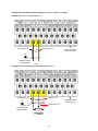
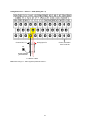
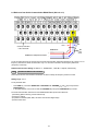
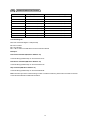
2.3.2 Screw specifications and recommended wire sizes
(1) Arrangement of main circuit terminals
The tables and figures given below show the screw specifications and wire sizes. Note that the terminal arrangements
differ depending on the inverter types. In each of the figures, two grounding terminals ( G) are not exclusive to the
power supply wiring (primary circuit) or motor wiring (secondary circuit).
Use crimp terminals covered with an insulation sheath or with an insulation tube.
The recommended wires for main circuit terminals are selected according to the sizes conforming to UL508C.
Table 2.5 Screw Specifications
Inverter type
Three-phase
230 V
EQ7-20P5-C
EQ7-2001-C
EQ7-2002-C
EQ7-2003-C
EQ7-2005-C
EQ7-2007-C
EQ7-2010-C
EQ7-2015-C
EQ7-2020-C
EQ7-2025-C
EQ7-2030-C
EQ7-2040-C
EQ7-2050-C
EQ7-2060-C
EQ7-2075-C
EQ7-2100-C
--EQ7-2125-C
--EQ7-2150-C
-------
Three-phase
460 V
EQ7-40P5-C
EQ7-4001-C
EQ7-4002-C
EQ7-4003-C
EQ7-4005-C
EQ7-4007-C
EQ7-4010-C
EQ7-4015-C
EQ7-4010-C
EQ7-4025-C
EQ7-4030-C
EQ7-4040-C
EQ7-4050-C
EQ7-4060-C
EQ7-4075-C
EQ7-4100-C
EQ7-4125-C
Refer to:
Main circuit
terminals
Auxiliary fan
power input
terminals
[R1, T1]
Screw
size
Tightening
Tightening
Tightening
Tightening
Screw
Screw
Screw
torque
torque
torque
torque
size
size
size
lb-in (N·m)
lb-in (N·m)
lb-in (N·m)
lb-in (N·m)
Figure A
M3.5
10.6 (1.2)
M3.5
10.6 (1.2)
Figure B
M4
15.9 (1.8)
M4
15.9 (1.8)
Figure C
M5
31.0 (3.5)
M5
31.0 (3.5)
Figure D
M6
51.3 (5.8)
Figure E
M8
119 (13.5)
M6
51.3 (5.8)
M8
119 (13.5)
--
M3.5
Figure F
M10
EQ7-4150-C
EQ7-4200-C
-EQ7-4250-C
EQ7-4300-C
EQ7-4350-C
EQ7-4450-C
EQ7-4500-C
EQ7-4600-C
EQ7-4700-C
EQ7-4800-C
EQ7-4900-C
EQ7-41000-C
Screw specifications
Auxiliary control
power input
Grounding
terminals
terminals
[R0, T0]
--
--
--
M3.5
10.6 (1.2)
10.6 (1.2)
239 (27)
Figure G
Figure M
Figure H
Figure I
Figure J
M12
425 (48)
M10
239 (27)
Figure K
Figure L
When the inverter power is ON, a high voltage is applied to the following terminals.
Main circuit terminals: L1/R, L2/S, L3/T, P1, P(+), N(-), DB, U, V, W, R0, T0, R1, T1, AUX-contact (30A, 30B, 30C,
Y5A, Y5C)
Insulation level
Main circuit - Enclosure
: Basic insulation (Overvoltage category III, Pollution degree 2)
Main circuit - Control circuit
: Reinforced insulation (Overvoltage category III, Pollution degree 2)
Relay output - Control circuit : Reinforced insulation (Overvoltage category II, Pollution degree 2)
An electric shock may occur.
2-5
Unit: inch (mm)
to
* Refer
Section
2.3.3 (9).
2-6
Table 2.6 Recommended Wire Sizes
Recommended wire size AWG (mm2)
Inverter type
Power supply
voltage
Variable
Torque mode
Constant
Torque mode
CT-Vector
mode
EQ7-20P5-C
EQ7-2001-C
EQ7-2002-C
EQ7-2003-C
EQ7-2005-C
EQ7-2007-C
-EQ7-2010-C
-EQ7-2015-C
EQ7-2020-C
Single-phase/ EQ7-2025-C
Three-phase EQ7-2030-C
230V
EQ7-2040-C
-EQ7-2050-C
-EQ7-2060-C
EQ7-2075-C
EQ7-2100-C
EQ7-20P5-C
EQ7-2001-C
EQ7-2002-C
EQ7-2003-C
EQ7-2005-C
EQ7-2007-C
EQ7-2050-C
-EQ7-2060-C
EQ7-2075-C
EQ7-2100-C
EQ7-20P5-C
EQ7-2001-C
EQ7-2002-C
EQ7-2003-C
EQ7-2005-C
EQ7-2007-C
EQ7-2010-C
-EQ7-2015-C
EQ7-2020-C
EQ7-2025-C
EQ7-2030-C
EQ7-2040-C
-EQ7-2050-C
-EQ7-2060-C
EQ7-2075-C
EQ7-2100-C
EQ7-2125-C
4/0 (107.2)
2/0 (67.4) 2
3/0 (85) 2
EQ7-2125-C
EQ7-2125-C
EQ7-2150-C
4/0 (107.2) 2
1 (42.4)
EQ7-2150-C
EQ7-2150-C
--
300 (152) 2
1/0 (53.5)
EQ7-40P5-C
EQ7-4001-C
EQ7-4002-C
EQ7-4003-C
EQ7-4005-C
EQ7-4007-C
-EQ7-4010-C
EQ7-4015-C
-EQ7-4020-C
-EQ7-4025-C
EQ7-4030-C
EQ7-4040-C
-EQ7-4050-C
EQ7-4060-C
Single-phase/ EQ7-4075-C
Three-phase EQ7-4100-C
460V
-EQ7-4125-C
EQ7-4150-C
EQ7-4200-C
EQ7-4250-C
EQ7-4300-C
EQ7-40P5-C
EQ7-4001-C
EQ7-4002-C
EQ7-4003-C
EQ7-4005-C
EQ7-4007-C
-EQ7-4010-C
EQ7-4015-C
-EQ7-4020-C
-EQ7-4025-C
EQ7-4030-C
EQ7-4040-C
-EQ7-4050-C
EQ7-4060-C
EQ7-4075-C
EQ7-4100-C
-EQ7-4125-C
EQ7-4150-C
EQ7-4200-C
EQ7-4250-C
EQ7-4300-C
EQ7-40P5-C
EQ7-4001-C
EQ7-4002-C
14 (2.1)
EQ7-4003-C
EQ7-4005-C
EQ7-4007-C
12 (3.3)
EQ7-4010-C
EQ7-4015-C
10 (5.3)
-EQ7-4020-C
8 (8.4)
-EQ7-4025-C
EQ7-4030-C
6 (13.3)
EQ7-4040-C
-4 (21.2)
EQ7-4050-C
EQ7-4060-C
3 (26.7)
EQ7-4075-C
2 (33.6)
EQ7-4100-C
1/0 (53.5)
-EQ7-4125-C
2/0 (67.4)
EQ7-4150-C
EQ7-4200-C
1/0 (53.5)
EQ7-4250-C
EQ7-4300-C
3/0 (85) 2
EQ7-4350-C 4/0 (107.2) 2
EQ7-4350-C
EQ7-4350-C
EQ7-4450-C
250 (127) 2
-EQ7-4450-C
--EQ7-4500-C
EQ7-4600-C
EQ7-4700-C
EQ7-4800-C
EQ7-4900-C
EQ7-41000-C
EQ7-4450-C
--EQ7-4500-C
EQ7-4600-C
EQ7-4700-C
EQ7-4800-C
----
--EQ7-4500-C
EQ7-4600-C
EQ7-4700-C
EQ7-4800-C
-EQ7-4900-C
EQ7-41000-C
--
300 (152) 2
400 (203) 2
250 (127) 2
300 (152) 2
400 (203) 2
500 (253) 2
600 (304) 2
350 (177) 3
500 (253) 3
600 (304) 3
EQ7-2010-C
-EQ7-2015-C
EQ7-2020-C
EQ7-2025-C
EQ7-2030-C
EQ7-2040-C
L1/R, L2/S,
L3/T
Grounding
[ G]
U, V, W
DCR
[P1, P(+)]
14 (2.1)
14 (2.1)
12 (3.3)
10 (5.3)
Braking
resistor
[P(+), DB]
14 (2.1)
14 (2.1)
10 (5.3)
12 (3.3)
10 (5.3)
8 (8.4)
8 (8.4)
8 (8.4)
10 (5.3)
8 (8.4)
6 (13.3)
4 (21.2)
3 (26.7)
2 (33.6)
2/0 (67.4)
3/0 (85)
Note: The wire sizes above are specified for 75C (167F) copper (Cu) wire.
2-7
6 (13.3)
4 (21.2)
6 (13.3)
4 (21.2)
3 (26.7)
2 (33.6)
1 (42.4)
1/0 (53.5)
3 (26.7)
2 (33.6)
14 (2.1)
4 (21.2)
3 (26.7)
2 (33.6)
1 (42.4)
2/0 (67.4)
4/0 (107.2)
4/0 (107.2)
250 (127)
3/0 (85) 2
4/0 (107.2)
2
350 (177)
--
500 (253)
300 (152) 2
4/0 (107.2)
2
14 (2.1)
14 (2.1)
12 (3.3)
12 (3.3)
12 (3.3)
10 (5.3)
10 (5.3)
10 (5.3)
10 (5.3)
8 (8.4)
8 (8.4)
8 (8.4)
6 (13.3)
6 (13.3)
4 (21.2)
6 (13.3)
4 (21.2)
2 (33.6)
2 (33.6)
1 (42.4)
1/0 (53.5)
1/0 (53.5)
4/0 (107.2)
3 (26.7)
2 (33.6)
1 (42.4)
1/0 (53.5)
2/0 (67.4)
3/0 (85)
4/0 (107.2)
250 (127)
350 (177)
3/0 (85)
1/0 (53.5)
4/0 (107.2)
2 (33.6)
250 (127)
3/0 (85) 2
350 (177)
250 (127) 2 600 (304)
300 (152) 2 4/0 (107.2)
2
350 (177) 2 250 (127) 2
400 (203) 2
300 (152) 2
300 (152) 2
350 (177) 2 350 (177) 2
400 (203) 2 400 (203) 2
500 (253) 2 500 (253) 2
600 (304) 2 300 (152) 3
400 (203) 3 400 (203) 3
600 (304) 3 600 (304) 3
500 (253) 4 400 (203) 4
--
Recommended wire size
AWG (mm2)
Terminals common to all inverters
Auxiliary control power input terminals [R0] and [T0]
Remarks
2 HP or above
14 (2.1)
Auxiliary fan power input terminals [R1] and [T1]
230 V series with 60 HP or above
460 V series with 125 HP or above
(2) Arrangement of control circuit terminals (common to all inverter types)
Terminal type
Recommended wiring size
2
(mm )*
Screw size: M3 (0.7 N·m)
0.75
Spring (screwless)
0.65 to 0.82 (AWG 19 or
18)
* Using wires exceeding the recommended sizes may lift the front cover
depending upon the number of wires used, impeding keypad's normal
operation.
2.3.3 Wiring precautions
Follow the rules below when performing wiring for the inverter.
(1) Make sure that the source voltage is within the rated voltage range specified on the nameplate.
(2) Be sure to connect the three-phase power wires to the main circuit power input terminals L1/R, L2/S and L3/T of
the inverter. If the power wires are connected to other terminals, the inverter will be damaged when the power is
turned ON.
(3) Always connect the grounding terminal to prevent electric shock, fire or other disasters and to reduce electric
noise.
(4) Use crimp terminals covered with insulated sleeves for the main circuit terminal wiring to ensure a reliable
connection.
(5) Keep the power supply wiring (primary circuit) and motor wiring (secondary circuit) of the main circuit, and control
circuit wiring as far away as possible from each other.
(6) After removing a screw from the main circuit terminal block, be sure to restore the screw even if no wire is
connected.
(7) Use the wiring guide to separate wiring. For inverters of 5 HP or below, the wiring guide separates the main circuit
wires and the control circuit wires. For those of 7.5 to 40 HP, it separates the upper and lower main circuit wires,
and control circuit wires. Be careful about the wiring order.
e.g. EQ7-4005-C
e.g. EQ7-2020-C
Preparing for the wiring guide
Inverters of 20 to 40 HP (three-phase, 230 V series) are sometimes lacking in wiring space for main circuit wires
depending upon the wire materials used. To assure a sufficient wiring space, remove the clip-off sections (see
below) as required with a nipper. Note that the enclosure rating of IP20 may not be ensured when the wiring guide
itself is removed to secure a space for thick main circuit wiring.
2-8
Before removal of clip-off sections
After removal of clip-off sections
Wiring Guide (e.g. EQ7-4025-C)
(8) In some types of inverters, the wires from the main circuit terminal block cannot be routed straight into the terminal.
Route such wires as shown below so that the front cover can be reinstalled.
(9) For inverters of 900 and 1000 HP, two L2/S input terminals are arranged vertically to the terminal block. When
connecting wires to these terminals, use the bolts, washers and nuts that come with the inverter, as shown below.
2-9
• When wiring the inverter to the power source, insert a recommended molded case circuit breaker (MCCB) or
residual-current-operated protective device (RCD)/earth leakage circuit breaker (ELCB) (with overcurrent
protection) in the path of each pair of power lines to inverters. Use the recommended devices within the
recommended current capacity.
• Be sure to use wires in the specified size.
• Tighten terminals with specified torque.
Otherwise, a fire could occur.
• When there is more than one combination of an inverter and motor, do not use a multiconductor cable for the
purpose of running the leads together.
• Do not connect a surge killer to the inverter's output (secondary) circuit.
Doing so could cause a fire.
• Ground the inverter in compliance with the national or local electric code.
• Be sure to ground the inverter's grounding terminals G.
Otherwise, an electric shock or fire could occur.
• Qualified electricians should carry out wiring.
• Be sure to perform wiring after turning the power OFF.
Otherwise, electric shock could occur.
• Be sure to perform wiring after installing the inverter unit.
Otherwise, electric shock or injuries could occur.
• Ensure that the number of input phases and the rated voltage of the product match the number of phases and
the voltage of the AC power supply to which the product is to be connected.
Otherwise, a fire or an accident could occur.
• Do not connect the power source wires to inverter output terminals (U, V, and W).
Doing so could cause fire or an accident.
2-10
2.3.4 Wiring of main circuit terminals and grounding terminals
This section shows connection diagrams with the Enable input function used.
SINK mode input by factory default
2-11
*1 Install a recommended molded case circuit breaker (MCCB) or residual-current-operated protective device
(RCD)/earth leakage circuit breaker (ELCB) (with overcurrent protection function) in the primary circuit of the
inverter to protect wiring. Ensure that the circuit breaker capacity is equivalent to or lower than the recommended
capacity.
*2 Install a magnetic contactor (MC) for each inverter to separate the inverter from the power supply, apart from the
MCCB or RCD/ELCB, when necessary.
Connect a surge absorber in parallel when installing a coil such as the MC or solenoid near the inverter.
*3 The R0 and T0 terminals are provided for inverters with a capacity of 2 HP or above.
To retain an alarm output signal ALM issued on inverter's programmable output terminals by the protective function
or to keep the keypad alive even if the main power has shut down, connect these terminals to the power supply
lines. Without power supply to these terminals, the inverter can run.
*4 Normally no need to be connected. Use these terminals when the inverter is equipped with a high power-factor,
regenerative PWM converter (RHC series).
*5 When connecting an optional DC reactor (DCR), remove the jumper bar from the terminals P1 and P(+).
EQ7-2100-C/EQ7-4100-C and larger HP models require a DCR (packed with the EQ7) to be connected.
Use a DCR when the capacity of the power supply transformer exceeds 500 kVA and is 10 times or more the
inverter rated capacity, or when there are thyristor-driven loads in the same power supply line.
*6 EQ7-2015-C/EQ7-4015-C and smaller have a built-in braking resistor (DBR) between the terminals P(+) and DB.
When connecting an external braking resistor (DBR), be sure to disconnect the built-in one.
*7 A grounding terminal for a motor. Use this terminal if needed.
*8 For control signal wires, use twisted or shielded-twisted wires. When using shielded-twisted wires, connect the
shield of them to the common terminals of the control circuit. To prevent malfunction due to noise, keep the control
circuit wiring away from the main circuit wiring as far as possible (recommended: 10 cm/3.9 inches or more). Never
install them in the same wire duct. When crossing the control circuit wiring with the main circuit wiring, set them at
right angles.
*9 The connection diagram shows factory default functions assigned to digital input terminals [X1] to [X7], [FWD] and
[REV], transistor output terminals [Y1] to [Y4], and relay contact output terminals [Y5A/C] and [30A/B/C].
*10 Switching connectors in the main circuits. For details, refer to "Instruction manual section 2.3.4
connectors" later in this section.
Switching
*11 Slide switches on the control printed circuit board (control PCB). Use these switches to customize the inverter
operations. For details, refer to Section 2.3.6 "Setting up the slide switches."
*12 When the Enable input function is not to be used, keep terminals [EN1]-[PLC] and terminals [EN2]-[PLC]
short-circuited using jumper wires. For opening and closing the hardware circuit between terminals [EN1] and [PLC]
and between [EN2] and [PLC], use safety components such as safety relays and safety switches that comply with
EN954-1 or EN ISO13849-1 Category 3 or higher.
*13 To bring the inverter into compliance with the European Standard, Low Voltage Directive EN61800-5-1, be sure to
insert the specified fuse in the primary circuit of the inverter.
Primary grounding terminal ( G) for inverter enclosure
Two grounding terminals ( G) are not exclusive to the power supply wiring (primary circuit) or motor wiring (secondary
circuit). Be sure to ground either of the two grounding terminals for safety and noise reduction. The inverter is designed
for use with safety grounding to avoid electric shock, fire and other disasters.
The grounding terminal for inverter enclosure should be grounded as follows:
1) Ground the inverter in compliance with the national or local electric code.
2) Use a thick grounding wire with a large surface area and keep the wiring length as short as possible.
Inverter output terminals U, V, and W and secondary grounding terminals ( G) for motor
Inverter’s output terminals should be connected as follows:
1) Connect the three wires of the 3-phase motor to terminals U, V, and W, aligning the phases each other.
2) Connect the secondary grounding wire to the grounding terminal ( G).
When there is more than one combination of an inverter and motor, do not use a multi-conductor cable for the
purpose of running the leads together.
2-12
DC reactor terminals P1 and P (+)
Connect a DC reactor (DCR) to these terminals for power factor correction.
1) Remove the jumper bar from terminals P1 and P(+).
2) Connect an optional DCR to those terminals.
• The wiring length should be 33 ft (10 m) or below.
• Do not remove the jumper bar when a DCR is not used.
• The EQ7-2100-C / EQ7-4100-C and higher types come with a DCR. Be sure to connect the DCR.
• If a PWM converter is connected to the inverter, no DCR is required.
Be sure to connect an optional DC reactor (DCR) when the capacity of the power supply transformer exceeds 500
kVA and is 10 times or more the inverter rated capacity.
Otherwise, a fire could occur.
DC braking resistor terminals P(+) and DB (for inverters of 40 HP or below)
Capacity
(HP)
Braking transistor
Built-in DC braking
resistor (DBR)
0.5 to 15
Built-in
Built-in
20 to 40
Built-in
None
Optional devices
External DC braking resistor
(with a larger capacity)
External DC braking resistor
Option mounting
steps required
1), 2), 3)
2), 3)
For inverters of 15 HP or below, if the capacity of the built-in DC braking resistor (DBR) is insufficient since the inverter
undergoes frequent start/stop or heavy inertial load, mount an optional external DC braking resistor (DBR) with a larger
capacity to increase the braking capability, using the following steps. Before mounting the external DBR, remove the
built-in DBR.
1) For inverters of 0.5 to 5 HP, disconnect the wiring of the built-in DBR from terminals P(+) and DB; for those of 7.5 to
15 HP, disconnect the wiring from terminal DB and the internal relay terminal (see the figure below).
Insulate the terminals of the disconnected wires with insulating tape or other materials.
2) Connect an optional DBR to terminals P(+) and DB.
The internal relay terminal on inverters of 7.5 to 15 HP is left unused.
3) Arrange the DBR and inverter so that the wiring length comes to 16 ft (5 m) or less and twist the two DBR wires or
route them together in parallel.
When connecting a DC braking resistor (DBR), never connect it to terminals other than terminals P(+) and DB.
Otherwise, a fire could occur.
2-13
DC link bus terminals P(+) and N(-)
Capacity
(HP)
Braking
transistor
Built-in DC braking
resistor (DBR)
Optional devices
Braking unit
50 to 1000
None
None
DC braking resistor
(DBR)
Devices and terminals
Inverter - Braking unit:
P(+) and N(-)
Braking unit -DBR:
P(+) and DB
1) Connecting an optional braking unit or DC braking resistor (DBR)
Inverters of 50 HP or above require both a braking unit and DBR.
Connect the terminals P(+) and N(-) of a braking unit to those on the inverter. Arrange the inverter and the braking
unit so that the wiring length comes to 16 ft (5 m) or less and twist the two wires or route them together in parallel.
Next, connect the terminals P(+) and DB of a DBR to those on the braking unit. Arrange the braking unit and DBR
so that the wiring length comes to 33 ft (10 m) or less and twist the two wires or route them together in parallel.
For details about the wiring, refer to the Braking Unit Instruction Manual.
2) Connecting other external devices
A DC link bus of other inverter(s) or a PWM converter is connectable to these terminals.
When you need to use the DC link bus terminals P(+) and N(-), consult your TECO-Westinghouse Motor
Company representative.
Switching connectors
Power switching connectors (CN UX) (on inverters of 125 HP or above for 460 V)
Inverters of 125 HP or above for 460 V are equipped with a set of switching connectors (male) which should be
configured according to the power source voltage and frequency. By factory default, a jumper (female connector) is set
to U1. If the power supply to the main power inputs (L1/R, L2/S, L3/T) or the auxiliary fan power input terminals (R1,
T1) matches the conditions listed below, change the jumper to U2.
For the switching instructions, see Figures 2.6 and 2.7.
(a) EQ7-4125-C to EQ7-4200-C
CN UX (red)
CN UX (red)
Connector
configuration
Power source voltage
398 to 440 V/50 Hz, 430 to 480 V/60 Hz
(Factory default)
380 to 398 V/50 Hz
380 to 430 V/60 Hz
(b) EQ7-4250-C to EQ7-41000-C
CN UX (red)
CN UX (red)
Connector configuration
Power source voltage
398 to 440 V/50 Hz, 430 to 480 V/60 Hz
(Factory default)
380 to 398 V/50 Hz,
380 to 430 V/60 Hz
The allowable power input voltage fluctuation is within -15% to +10% of the power source voltage.
2-14
Fan power supply switching connectors (CN R and CN W) (on inverters of 60 HP or above for 230 V and
those of 125 HP or above for 460 V)
The standard EQ7 series accepts DC-linked power input in combination with a PWM converter. Inverters of 60 HP or
above for 230 V and those of 125 HP or above for 460 V, however, contain AC-driven components such as AC fans. To
supply AC power to those components, exchange the CN R and CN W connectors as shown below and connect the
AC power line to the auxiliary fan power input terminals (R1, T1).
For the switching instructions, see Figures 2.6 and 2.7.
(a) EQ7-2060-C to EQ7-2125-C, EQ7-4125-C to EQ7-4200-C
CN R (red)
CN W (white)
CN W (white)
CN R (red)
Connector configuration
Use conditions
When not using terminal R1 or T1
(Factory default)
When using terminals R1 and T1
• Feeding the DC-linked power
• Combined with a PWM converter
b) EQ7-2150-C, EQ7-4150-C to EQ7-41000-C
Connector
configuration
CN R
(red)
CN W
(white)
Use conditions
When not using terminal R1 or T1
(Factory default)
CN R
(red)
CN W
(white)
When using terminals R1 and T1
• Feeding the DC-linked power
• Combined with a PWM converter
By factory default, the fan power supply switching connectors CN R and CN W are set on the FAN and NC
positions, respectively. Do not exchange them unless you drive the inverter with a DC-linked power supply.
Wrong configuration of these switching connectors cannot drive the cooling fans, causing a heat sink overheat
alarm 0h1 or a charger circuit alarm pbf.
Location of the switching connectors
The switching connectors are located on the power printed circuit board (power PCB) as shown below.
Keypad enclosure
Power switching
connectors (CN UX)
Fan power
supply switching
connectors
(CN R and
CN W)
Auxiliary fan
power input
terminals
Auxiliary
power input
terminals
Power PCB
Auxiliary fan power input
terminals
Power switching
connectors (CN UX)
Auxiliary power input
terminals
(a) EQ7-2060-C to EQ7-2125-C,
EQ7-4125-C to EQ7-4200-C
(b) EQ7-2150-C,
EQ7-4250-C to EQ7-41000-C
Figure 2.6 Location of Switching Connectors and Auxiliary Power Input Terminals
2-15
Fan power
supply
switching
connectors
(CN R and
CN W)
To remove each of the jumpers, pinch its upper side
between your fingers, unlock its fastener, and pull it up.
When mounting it, fit the jumper over the connector until it
snaps into place.
Figure 2.7 Inserting/Removing the Jumpers
Main circuit power input terminals L1/R, L2/S, and L3/T (three-phase input)
The three-phase input power lines are connected to these terminals.
1) For safety, make sure that the molded case circuit breaker (MCCB) or magnetic contactor (MC) is turned OFF
before wiring the main circuit power input terminals.
2) Connect the main circuit power supply wires (L1/R, L2/S and L3/T) to the input terminals of the inverter via an
MCCB or residual-current-operated protective device (RCD)/earth leakage circuit breaker (ELCB)*, and an MC if
necessary.
It is not necessary to align phases of the power supply wires and the input terminals of the inverter with each other.
* With overcurrent protection
It is recommended to insert a manually operable magnetic contactor (MC) that allows you to disconnect the
inverter from the power supply in an emergency (e.g., when the protective function is activated), preventing a
failure or accident from causing secondary disasters.
Auxiliary control power input terminals R0 and T0 (on inverters of 2 HP or above)
In general, the inverter runs normally without power supplied to the auxiliary control power input terminals R0 and T0. If
the inverter main power is shut down, however, no power is supplied to the control circuit so that the inverter cannot
issue a variety of output signals or display on the keypad.
To retain an alarm output signal ALM issued on inverter's programmable output terminals by the protective function or
to keep the keypad alive even if the main power has shut down, connect the auxiliary control power input terminals R0
and T0 to the power supply lines. If a magnetic contactor (MC) is installed in the inverter's primary circuit, connect the
primary circuit of the MC to these terminals R0 and T0.
Terminal rating:
200 to 240 VAC, 50/60 Hz, Maximum current 1.0 A (230 V series with 40 HP or below)
200 to 230 VAC, 50/60 Hz, Maximum current 1.0 A (230 V series with 50 HP or above)
380 to 480 VAC, 50/60 Hz, Maximum current 0.5 A (460 V series)
When introducing a residual-current-operated protective device (RCD)/earth leakage circuit breaker (ELCB),
connect its output (secondary) side to terminals R0 and T0. Connecting its input (primary) side to those
terminals causes the RCD/ELCB to malfunction since the input power voltage to the inverter is three-phase but
the one to terminals R0 and T0 is single-phase. To avoid such problems, be sure to insert an isolation
transformer or auxiliary B contacts of a magnetic contactor in the location shown in Figure 2.8.
Figure 2.8 Connection Example of Residual-current-operated Protective Device (RCD)/
Earth Leakage Circuit Breaker (ELCB)
2-16
When connecting a PWM converter with an inverter, do not connect the power supply line directly to terminals
R0 and T0. If a PWM is to be connected, insert an isolation transformer or auxiliary B contacts of a magnetic
contactor at the power supply side.
For connection examples at the PWM converter side, refer to the PWM Converter Instruction Manual.
Figure 2.9 Connection Example of PWM Converter
Auxiliary fan power input terminals R1 and T1
Inverters of 60 HP or above for 230 V and those of 125 HP or above for 460 V are equipped with terminals R1 and T1.
Only if the inverter works with the DC-linked power input whose source is a PWM converter, these terminals are used
to feed AC power to the fans, while they are not used in any power system of ordinary configuration.
In this case, set up the fan power supply switching connectors (CN R and CN W).
Terminal rating:
200 to 220 VAC/50 Hz, 200 to 230 VAC/60 Hz, Maximum current 1.0 A (230 V series with 60 HP or above)
380 to 440 VAC/50 Hz, 380 to 480 VAC/60 Hz, Maximum current 1.0 A (460 V series with 125 to 800 HP)
380 to 440 VAC/50 Hz, 380 to 480 VAC/60 Hz, Maximum current 2.0 A (460 V series with 900 and 1000 HP)
2-17
2.3.5 Wiring for control circuit terminals
This section shows connection diagrams with the Enable input function used.
In general, the covers of the control signal wires are not specifically designed to withstand a high voltage (i.e.,
reinforced insulation is not applied). Therefore, if a control signal wire comes into direct contact with a live
conductor of the main circuit, the insulation of the cover might break down, which would expose the signal wire
to a high voltage of the main circuit. Make sure that the control signal wires will not come into contact with live
conductors of the main circuit.
Failure to observe these precautions could cause electric shock or an accident.
Noise may be emitted from the inverter, motor and wires.
Take appropriate measures to prevent the nearby sensors and devices from malfunctioning due to such noise.
An accident could occur.
Connecting/disconnecting wires to/from a control circuit terminal of spring (screwless) type
Strip the wire end by 8 to 10 mm/0.31 to 0.39 inch as shown below.
Strip length of wire end
8 to 10 mm
0.31 to 0.39 inch
Type of screwdriver (tip shape)
Flat (0.6 3.5 mm/0.024 0.14 inch)
For strand wires, the strip length specified above should apply after twisting of them.
If the strip length is out of the specified range, the wire may not be firmly clamped or may be
short-circuited with other wires.
Twist the end of the stripped wires for easy insertion and insert it firmly into the wire inlet on the control circuit
terminal. If the insertion is difficult, hold down the clamp release button on the terminal with a flat screwdriver.
When disconnecting the wires from the terminal, hold down the clamp release button on the terminal with a flat
screwdriver and pull out the wires. Connecting wire to terminal disconnecting wire from terminal
Flat screwdriver
Wires
Wires
Wire inlet
Clamp release button
2-18
Table 2.7 lists the symbols, names and functions of the control circuit terminals. The wiring to the control circuit
terminals differs depending upon the setting of the function codes, which reflects the use of the inverter. Route wires
properly to reduce the influence of noise.
Symbol
Name
Functions
[13]
Power supply
for the
potentiometer
Power supply (+10 VDC) for an external frequency command potentiometer
(Variable resistor: 1 to 5k)
The potentiometer of 1/2 W rating or more should be connected.
[12]
Analog
setting
voltage input
(1) The frequency is commanded according to the external voltage input.
• 0 to 10 VDC/0 to 100% (Normal operation)
• +10 to 0 VDC/0 to 100% (Inverse operation)
(2) In addition to frequency setting, PID command, PID feedback signal, auxiliary frequency
command setting, ratio setting, torque limiter level setting, or analog input monitor can be
assigned to this terminal.
(3) Hardware specifications
• Input impedance: 22k
• The maximum input is 15 VDC, however, the voltage higher than 10 VDC is handled
as 10 VDC.
• Inputting a bipolar analog voltage (0 to 10 VDC) to terminal [12] requires setting function
code C35 to "0."
[C1]
Analog
setting
current input
(1) The frequency is commanded according to the external current input.
• 4 to 20 mA DC/0 to 100% (Normal operation)
• 20 to 4 mA DC/0 to 100 % (Inverse operation)
(2) In addition to frequency setting, PID command, PID feedback signal, auxiliary frequency
command setting, ratio setting, torque limiter level setting, or analog input monitor can be
assigned to this terminal.
(3) Hardware specifications
• Input impedance: 250
• The maximum input is +30 mA DC, however, the current larger than +20 mA DC is
handled as +20 mA DC.
PTC/NTC
thermistor
input
(1) Connects PTC (Positive Temperature
Coefficient)/NTC (Negative Temperature
Coefficient) thermistor for motor
protection. Ensure that the slide switch
SW5 on the control PCB is turned to the
PTC/NTC position (see section 2.3.6
"Setting up the slide switches").
Analog input
Classification
Table 2.7 Symbols, Names and Functions of the Control Circuit Terminals
The figure shown at the right illustrates the
internal circuit diagram where SW5
(switching the input of terminal [C1]
between C1 and PTC/NTC) is turned to
the PTC/NTC position. For details on
SW5, refer to Instruction manual section
2.3.6 "Setting up the slide switches." In
this case, you must change data of the
function code H26.
[V2]
[11]
Figure 2.10 Internal Circuit Diagram
(SW5 Selecting PTC/NTC)
Analog
setting
voltage input
(1) The frequency is commanded according to the external voltage input.
• 0 to 10 VDC/0 to 100 % (Normal operation)
• +10 to 0 VDC/0 to 100% (Inverse operation)
(2) In addition to frequency setting, PID command, PID feedback signal, auxiliary frequency
command setting, ratio setting, torque limiter level setting, or analog input monitor can be
assigned to this terminal.
(3) Hardware specifications
• Input impedance: 22k
• The maximum input is 15 VDC, however, the voltage higher than 10 VDC is handled
as 10 VDC.
• Inputting a bipolar analog voltage (0 to 10 VDC) to terminal [V2] requires setting
function code C45 to "0."
Analog
common
Common for analog input/output signals ([13], [12], [C1], [V2], [FM1] and [FM2]).
Isolated from terminals [CM] and [CMY].
2-19
Classification
Table 2.7 Symbols, Names and Functions of the Control Circuit Terminals (Continued)
Symbol
Name
Functions
- Since low level analog signals are handled, these signals are especially susceptible to the external noise
effects. Route the wiring as short as possible (within 66 ft (20 m)) and use shielded wires. In principle, ground
the shielded sheath of wires; if effects of external inductive noises are considerable, connection to terminal [11]
may be effective. As shown in Figure 2.11, be sure to ground the single end of the shield to enhance the shield
effect.
- Use a twin-contact relay for low level signals if the relay is used in the control circuit. Do not connect the relay's
contact to terminal [11].
- When the inverter is connected to an external device outputting the analog signal, the external device may
malfunction due to electric noise generated by the inverter. If this happens, according to the circumstances,
connect a ferrite core (a toroidal core or equivalent) to the device outputting the analog signal or connect a
capacitor having the good cut-off characteristics for high frequency between control signal wires as shown in
Figure 2.12.
- Do not apply a voltage of +7.5 VDC or higher to terminal [C1]. Doing so could damage the internal control
circuit.
Digital input
Figure 2.11 Connection of Shielded Wire
[X1]
Digital input 1
[X2]
Digital input 2
[X3]
Digital input 3
[X4]
Digital input 4
[X5]
Digital input 5
[X6]
Digital input 6
[X7]
Digital input 7
[FWD]
Run forward
command
[REV]
Run reverse
command
Figure 2.12 Example of Electric Noise Reduction
(1) Various signals such as "Coast to a stop," "Enable external alarm trip," and "Select
multi-frequency" can be assigned to terminals [X1] to [X7], [FWD] and [REV] by setting
function codes E01 to E07, E98, and E99. For details, refer to Chapter 4, Section 4.2
"Details of Function Codes."
(2) Input mode, i.e. SINK/SOURCE, is changeable by using the slide switch SW1. (Refer to
Instruction manual section 2.3.6 "Setting up the slide switches.")
(3) Switches the logic value (1/0) for ON/OFF of the terminals [X1] to [X7], [FWD], or [REV]. If
the logic value for ON of the terminal [X1] is 1 in the normal logic system, for example, OFF
is 1 in the negative logic system and vice versa.
(4) Digital input terminal [X7] can be defined as a pulse train input terminal with the function
codes.
Maximum wiring length 20 m/66 ft
Maximum input pulse 30 kHz: When connected to a pulse generator with open collector
transistor output
(Needs a pull-up or pull-down resistor. See notes on page
2-22.)
100 kHz: When connected to a pulse generator with complementary
transistor output
For the settings of the function codes, refer to Chapter 4 "FUNCTION CODES."
(Digital input circuit specifications)
Item
Min.
Operating
voltage
(SINK)
ON level
0V
2V
OFF level
22 V
27 V
Operating
voltage
(SOURCE)
ON level
22 V
27 V
OFF level
0V
2V
2.5 mA
5 mA
Operating current at ON
(Input voltage is at 0 V)
(For [X7])
Figure 2.13 Digital Input Circuit
2-20
Max.
Allowable leakage current at
OFF
(9.7 mA) (16 mA)
0.5 mA
Classification
Table 2.7 Symbols, Names and Functions of the Control Circuit Terminals (Continued)
Symbol
[EN1]
[EN2]
Name
Functions
Enable inputs
(1) Turning off the circuit between terminals [EN1] and [PLC] or terminals [EN2] and [PLC]
stops the inverter's output transistor. (Safe Torque Off: STO)
(2) These terminals are exclusively used for the source mode input and cannot be switched to
the sink mode.
(3) If either one of these input terminals is kept OFF for 50 ms or more, the inverter interprets it
as a discrepancy, causing an alarm ecf. This alarm state can be cleared only by turning the
inverter power off and on clears this alarm.
For details of connection to this terminal and precautions, refer to User Manual Chapter 9,
Section 9.4 "Compliance with EN954-1, Category 3."
<Terminal [EN1] [EN2] circuit specification>
Item
<Control circuit>
+24 VDC
[PLC]
Photocoupler
[EN1]
Operating
voltage
Min.
Max.
ON level
22 V
27 V
OFF level
0V
2V
5.4k
Operating current at ON
2.5 mA 5 mA
(Input voltage is at 27 V)
Allowable leakage current at
0.5 mA
OFF
[EN2]
5.4k
[PLC]
PLC signal
power
(1) Connects to the power supply of PLC output signals.
Rated voltage: +24 VDC (Allowable range: +22 to +27 VDC), Maximum 100 mA DC
(2) This terminal also supplies power to the load connected to the transistor output terminals.
Refer to "Transistor output" described later in this table for more.
[CM]
Digital input
common
Common terminal for digital input signals
This terminal is electrically isolated from the terminals [11]s and [CMY].
Using a relay contact to turn [X1] to [X7], [FWD], or [REV] ON or OFF
Figure 2.14 shows two examples of a circuit that uses a relay contact to turn control signal input [X1] to [X7],
[FWD], or [REV] ON or OFF. In circuit (a), the slide switch SW1 is turned to SINK, whereas in circuit (b) it is turned
to SOURCE.
Note: To configure this kind of circuit, use a highly reliable relay.
<Control circuit>
[PLC]
<Control circuit>
SINK
[PLC]
SINK
SOURCE
SOURCE
[X1] t o [X7],
[FWD], [REV]
+24 VDC
+24 VDC
Digital input
[CM]
[X1] to [X7],
[FWD], [REV]
Photocoupler
[CM]
Photocoupler
[CM]
(a) With the switch turned to SINK
(b) With the switch turned to SOURCE
Figure 2.14 Circuit Configuration Using a Relay Contact
Using a programmable logic controller (PLC) to turn [X1] to [X7], [FWD], or [REV] ON or OFF
Figure 2.15 shows two examples of a circuit that uses a programmable logic controller (PLC) to turn control signal
input [X1] to [X7], [FWD], or [REV] ON or OFF. In circuit (a), the slide switch SW1 is turned to SINK, whereas in
circuit (b) it is turned to SOURCE.
In circuit (a) below, short-circuiting or opening the transistor's open collector circuit in the PLC using an external
power supply turns ON or OFF control signal [X1] to [X7], [FWD], or [REV]. When using this type of circuit, observe
the following:
- Connect the + node of the external power supply (which should be isolated from the PLC's power) to terminal
[PLC] of the inverter.
- Do not connect terminal [CM] of the inverter to the common terminal of the PLC.
2-21
Name
Programmable
logic controller
Functions
Programmable
logic controller
<Control circuit>
[PLC]
SINK
[PLC]
SOURCE
Digital input
[X1] t o [ X7],
[FWD], [REV]
<Control circuit>
SINK
+24 VDC
Symbol
+24 VDC
Classification
Table 2.7 Symbols, Names and Functions of the Control Circuit Terminals (Continued)
SOURCE
[X1] to [X7],
[FWD], [REV]
Photocoupler
Photocoupler
[CM]
[CM]
(a) With the switch turned to SINK
(b) With the switch turned to SOURCE
Figure 2.15 Circuit Configuration Using a PLC
For details about the slide switch setting, refer to Instruction manual for section 2.3.6 "Setting up the slide switches."
For inputting a pulse train through the digital input terminal [X7]
• Inputting from a pulse generator with an open collector transistor output
Stray capacity on the wiring between the pulse generator and the inverter may disable transmission of the pulse
train. As a countermeasure against this problem, insert a pull-up resistor between the open collector output
signal (terminal [X7]) and the power source terminal (terminal [PLC]) if the switch selects the SINK mode input;
insert a pull-down resistor between the output signal and the digital common terminal (terminal [CM]) if the switch
selects the SOURCE mode input.
A recommended pull-up/down resistor is 1k 2 W. Check if the pulse train is correctly transmitted because stray
capacity is significantly affected by the wire types and wiring conditions.
[FM1]
[FM2]
Analog
monitor
Both terminals output monitor signals for analog DC voltage (0 to +10 V) or analog DC current
(+4 to +20 mA). The output form (VO/IO) for each of [FM1] and [FM2] can be switched with the
slide switches on the control PCB and the function codes, as listed below.
Terminal
[FM1]
Analog output
[FM2]
Output form
Terminal function is
Content is
specified by:
Analog DC voltage Analog DC current specified by:
Slide switch SW4
VO1
IO1
Function code
F31
Function code F29
0
1
Slide switch SW6
VO2
IO2
Function code
F35
Function code F32
0
1
The signal content can be selected from the following with function codes F31 and F35.
• Output frequency
• Output current
• Output voltage
• Output torque
• Load factor
• Input power
• PID feedback amount
• Speed (PG feedback value)
• DC link bus voltage
• Universal AO
• Motor output
• Calibration
• PID command
• PID output
* Input impedance of the external device: Min. 5k (at 0 to 10 VDC output)
(While the terminal is outputting 0 to 10 VDC, it is capable of driving up to two analog
voltmeters with 10 k impedance.)
* Input impedance of the external device: Max. 500 (at 4 to 20 mA DC output)
* Adjustable range of the gain: 0 to 300%
[11]
Analog
common
Two common terminals for analog input and output signals.
These terminals are electrically isolated from terminals [CM] and [CMY].
2-22
Symbol
Name
[Y1]
Transistor
output 1
[Y2]
Transistor
output 2
[Y3]
Transistor
output 3
Functions
(1) Various signals such as inverter running, speed/freq. arrival and overload early warning can
be assigned to any terminals, [Y1] to [Y4] by setting function code E20 to E24. Refer to
Chapter 4, Section 4.2 "Details of Function Codes" for details.
(2) Switches the logic value (1/0) for ON/OFF of the terminals between [Y1] to [Y4], and [CMY].
If the logic value for ON between [Y1] to [Y4] and [CMY] is 1 in the normal logic system, for
example, OFF is 1 in the negative logic system and vice versa.
(Transistor output circuit specification)
<Control circuit>
Photocoupler
Item
Current
[Y1]
to
[Y4]
31 to 35 V
[CMY]
Operation
voltage
Voltage
Classification
Table 2.7 Symbols, Names and Functions of the Control Circuit Terminals (Continued)
Max.
ON level
2V
OFF level
27 V
Maximum current at ON
50 mA
Leakage current at OFF
0.1 mA
Figure 2.16 Transistor Output Circuit
Transistor output
Figure 2.17 shows examples of connection between the control circuit and a PLC.
[Y4]
- When a transistor output drives a control relay, connect a surge-absorbing diode
across relay’s coil terminals.
Transistor
output 4
- When any equipment or device connected to the transistor output needs to be
supplied with DC power, feed the power (+24 VDC: allowable range: +22 to +27 VDC,
100 mA max.) through the [PLC] terminal. Short-circuit between the terminals [CMY]
and [CM] in this case.
[CMY]
Transistor
output
common
Common terminal for transistor output signals
This terminal is electrically isolated from terminals [CM] and [11]s.
Connecting programmable logic controller (PLC) to terminal [Y1], [Y2], [Y3] or [Y4]
Figure 2.17 shows two examples of circuit connection between the transistor output of the inverter’s control
circuit and a PLC. In example (a), the input circuit of the PLC serves as a SINK for the control circuit output,
whereas in example (b), it serves as a SOURCE for the output.
<Control circuit>
Programmable
logic controller
C0
Current
Photocoupler
[Y1]
to
[Y4]
Current
SINK input
[Y1]
to
[Y4]
31 to
35 V
+24 VDC
31 to
35 V
[CMY]
+24 VDC
Photocoupler
<Control circuit>
Programmable
logic controller
[CMY]
SOURCE input
C0
(a)
PLC serving as SINK
(b)
PLC serving as SOURCE
Figure 2.17 Connecting PLC to Control Circuit
Relay output
[Y5A/C]
General
purpose relay
output
(1) A general-purpose relay contact output usable as well as the function of the transistor output
terminal [Y1], [Y2], [Y3] or [Y4].
Contact rating: 250 VAC 0.3 A, cos = 0.3, 48 VDC, 0.5 A
(2) Switching of the normal/negative logic output is applicable to the following two contact
output modes: "Active ON" (Terminals [Y5A] and [Y5C] are closed (excited) if the signal is
active.) and "Active OFF" (Terminals [Y5A] and [Y5C] are opened (non-excited) if the signal
is active while they are normally closed.).
2-23
Classification
Table 2.7 Symbols, Names and Functions of the Control Circuit Terminals (Continued)
Symbol
Communication
Relay output
[30A/B/C]
Name
Alarm relay
output
(for any error)
Functions
(1) Outputs a contact signal (SPDT) when a protective function has been activated to stop
the motor.
Contact rating: 250 VAC, 0.3A, cos = 0.3, 48 VDC, 0.5A
(2) Any one of output signals assigned to terminals [Y1] to [Y4] can also be assigned to this
relay contact to use it for signal output.
(3)
Switching of the normal/negative logic output is applicable to the following two
contact output modes: "Active ON" (Terminals [30A] and [30C] are closed (excited) if the
signal is active.) and "Active OFF" (Terminals [30A] and [30C] are opened (non-excited) if
the signal is active while they are normally closed.).
[DX+]/
[DX-]/
[SD]
RS-485
communications
port 2
(Terminals on
control PCB)
A communications port transmits data through the RS-485 multipoint protocol between the
inverter and a computer or other equipment such as a PLC.
RJ-45
connector
for the
keypad
RS-485
communications
port 1
(Standard RJ-45
connector)
(1) Used to connect the inverter with the keypad. The inverter supplies the power to the
keypad through the pins specified below. The extension cable for remote operation also
uses wires connected to these pins for supplying the keypad power.
(2) Remove the keypad from the standard RJ-45 connector and connect the RS-485
communications cable to control the inverter through the PC or PLC (Programmable
Logic Controller). For setting of the terminating resistor, refer to Section 2.3.6 "Setting up
the slide switches."
(For setting of the terminating resistor, refer to Section 2.3.6 "Setting up the slide switches.")
Figure 2.18 RJ-45 Connector and its Pin Assignment*
* Pins 1, 2, 7, and 8 are exclusively assigned to power lines for the keypad, so do not
use those pins for any other equipment.
2-24
Wiring for control circuit terminals
For EQ72125-C, EQ72150-C and EQ74250-C to EQ741000-C
(1) As shown in Figure 2.19, route the control circuit wires along the left side panel to the outside of the inverter.
(2) Secure those wires to the wiring support, using a cable tie (e.g., Insulok) with 0.15 inch (3.8 mm) or less in width
and 0.059 inch (1.5 mm) or less in thickness.
Cable tie
Control circuit terminal block
Wiring support
Wiring for control
circuit terminals
Section A
Details of Section A
Left side panel
Wiring for control
circuit terminals
Figure 2.19 Wiring Route and Fixing Position for the Control Circuit Wires
- Route the wiring of the control circuit terminals as far from the wiring of the main circuit as possible.
Otherwise electric noise may cause malfunctions.
- Fix the control circuit wires with a cable tie inside the inverter to keep them away from the live parts of the
main circuit (such as the terminal block of the main circuit).
2.3.6 Setting up the slide switches
Before changing the switches or touching the control circuit terminal symbol plate, turn OFF the power and wait at
least five minutes for inverters of 40 HP or below, or at least ten minutes for those of 50 HP or above. Make
sure that the LED monitor and charging lamp are turned OFF. Further, make sure, using a multimeter or a similar
instrument, that the DC link bus voltage between the terminals P(+) and N(-) has dropped to the safe level (+25 VDC
or below).
An electric shock may result if this warning is not heeded as there may be some residual electric charge in
the DC bus capacitor even after the power has been turned OFF.
Switching the slide switches located on the control PCB allows you to customize the operation mode of the analog
output terminals, digital I/O terminals, and communications ports. The locations of those switches are shown in Figure
2.20.
To access the slide switches, remove the front cover so that you can see the control PCB. For inverters of 50 HP or
above, open also the keypad enclosure.
For details on how to remove the front cover and how to open and close the keypad enclosure, refer to Section
2.3.1 "Removing and mounting the front cover and the wiring guide."
2-25
Table 2.8 lists function of each slide switch.
Table 2.8 Function of Each Slide Switch
Switch
Function
SW1
Switches the service mode of the digital input terminals between SINK and SOURCE.
▪ This switches the input mode of digital input terminals [X1] to [X7], [FWD] and [REV] to be
used as the SINK or SOURCE mode.
▪ The factory default is SINK.
SW2
Switches the terminating resistor of RS-485 communications port on the inverter ON and OFF.
(RS-485 communications port 2, on the control PCB)
▪ If the inverter is connected to the RS-485 communications network as a terminating device,
turn SW2 to ON.
SW3
Switches the terminating resistor of RS-485 communications port on the inverter ON and OFF.
(RS-485 communications port 1, for connecting the keypad)
▪ To connect a keypad to the inverter, turn SW3 to OFF. (Factory default)
▪ If the inverter is connected to the RS-485 communications network as a terminating device,
turn SW3 to ON.
Switches the output form of analog output terminals [FM1] and [FM2] between voltage and
current.
When changing the setting of SW4 and SW6, also change the data of function codes F29 and
F32, respectively.
[FM1]
SW4/SW6
Output form
[FM2]
SW4
F29 data
SW6
F32 data
Voltage output (Factory default)
VO1
0
VO2
0
Current output
IO1
1
IO2
1
Switches the property of the analog input terminal [C1] between analog setting current input,
PTC thermistor input, and NTC thermistor input.
When changing this switch setting, also change the data of function code H26.
SW5
H26 data
C1
0
PTC thermistor input
PTC/NTC
1 (alarm) or 2
(warning)
NTC thermistor input
PTC/NTC
3
Function
SW5
Analog setting current input (Factory default)
Figure 2.20 shows the location of slide switches on the control PCB for the input/output terminal configuration.
Switch Configuration and Factory Defaults
SW1
SW2
OFF
SW4/SW
6
SW3
OFF
VO1/VO2
SW5
C1
Factory
default
SINK
SOURCE
ON
--ON
IO1/IO2
PTC/NTC
Figure 2.20 Location of the Slide Switches
on the Control PCB
To move a switch slider, use a tool with a narrow tip (e.g., a tip of tweezers). Be careful not to touch other
electronic parts, etc. If the slider is in an ambiguous position, the circuit is unclear whether it is turned ON
or OFF and the digital input remains in an undefined state. Be sure to place the slider so that it contacts
either side of the switch.
2-26
2.4 Mounting and Connecting the Keypad
The standard keypad TP-G1W-J1 meets UL Type 4 (NEMA4) by itself.
On the panel or at a remote site
The keypad can be mounted on the panel wall as shown below or installed at a remote site for operation on hand.
Mount the keypad with four M3 x 12 screws provided--two fine thread
screws and two coarse thread tapping screws. The recommended
tightening torque is 6.2 lb-in (0.7 Nm).
For panel cutting dimensions, refer to Chapter 11, Section 11.3.2.
0.51 inches (13 mm)
(Effective length of
tapping screw)
Panel
RJ-45
connector
M3 x 12
(Fine thread screws)
M3 x 12
(Coarse thread tapping screws)
0.43 inches (11 mm)
(Effective length of
screw)
Inside the panel
0.05 to 0.09 inch*
(1.2 to 2.3 mm)
* If the thickness of the panel wall is out of
the range specified above, use screws of
an appropriate length.
Figure 2.21 Mounting the Keypad on the Panel Wall
To mount the keypad on a place other than an inverter, the parts listed below are needed.
Parts name
Type
Remarks
Extension cable
LAN cable
0BASE-T/100BASE-TX straight type cable
compliant with US ANSI/TIA/EIA-568A Category 5. (Less than 66 ft (20 m))
On the inverter
To remove the keypad from the inverter, pull it forward while holding down the hook (pointed by the arrow in Figure
2.22). When mounting it, put the keypad back into place in the reverse order of removal.
Figure 2.22 Removing the Keypad
2-27
2.5 Input Power and Motor Connection
Checking prior to powering on
Fig.2.23 below shows the electrical connections for the input power and motor terminals for various EQ7 DRIVE
models. Verify the input power and motor terminals of the model you are installing. WITH POWER OFF, make the
appropriate connections.
Make sure to follow good wiring practices and all applicable codes. Ensure that the equipment is grounded
properly as shown.
DANGER, LETHAL VOLTAGES ARE PRESENT- Before applying power to the EQ7 drive, ensure that the
terminal cover is fastened and all wiring connections are secure. After the power has been turned OFF, wait at
least ten minutes until the charge indicator extinguishes completely before touching any wiring, circuit boards
or components.
WARNING DO NOT CONNECT ANY OF THE
FOLLOWING TERMINALS TO EARTH GROUND
DB
INPUT POWER
GND
L1/R
L2/S
P1
P(+)
*1
*1
N(-)
MOTOR
U
L3/T
V
W
GND
EQ7
(W/T3)
(U/T1)
(R/L1)
(S/L2)
(T/L3)
To change direction of
motor rotation swap any
two of the three motor
leads.
Ground
(V/T2)
Ground
Input
Protection
(Fuse or Magnetic
Contactor)
P1
P(+)
L1 L2 L3
Use L1, L2, L3 for
3Ø Input Power
3Ø Induction
motor
Use L1 & L3 for
2
1Ø Input Power *
Connect
frame to
ground
Fig. 2.23
*1. Refer to page 2-11 & 2-12 for connecting a DC reactor from the terminals P1 and P(+).
*2. Make sure the drive is properly sized for single phase input (consult factory).
(Refer to Table 2.6 Recommended Wire Sizes in this manual).
2-28
DCR
Never connect power supply wires to the EQ7 drive output terminals U, V, and W. Doing so and turning
the power ON damages the inverter.
Be sure to connect the grounding wires of the EQ7 drive and the motor to the ground electrodes.
Otherwise, an electric shock could occur.
Check the following before powering on the EQ7 drive.
1) Check that the wiring is correct. Especially check the wiring to the EQ7 drive input terminals L1/R, L2/S
and L3/T and output terminals U, V, and W. Also check that the grounding wires are connected to the
grounding terminals ( G) correctly. See Figure 2.23.
2) Check the control circuit terminals and main circuit terminals for short circuits or ground faults.
3) Check for loose terminals, connectors and screws.
4) Check that the motor is separated from mechanical equipment.
5) Make sure that all switches of devices connected to the inverter are turned OFF. Powering on the
inverter with any of those switches being ON may cause an unexpected motor operation.
6) Check that safety measures are taken against runaway of the equipment. Also ensure that all safety
guards are in place to prevent human injury.
2-29
Chapter 3 Operation using the Keypad
3.1 LED Monitor, LCD Monitor, and Keys
The keypad allows you to start and stop the motor, view various data including maintenance information and alarm
information, configure function codes, monitor I/O signal status, copy data, and calculate the load factor.
7-segment LED Monitor
Indication units
LCD monitor
RUN key (forward)
Program
LED light
key
Shift key
RUN key (reverse)
Reset key
STOP key
UP key
Remote/Local key
Function/Data key
DOWN key
Table 3.1: Overview of Keypad Functions
Item
Monitor
Functions
Five-digit, 7-segment LED monitor which displays the following according to the operation modes:
In Run mode: Running status information (e.g., output frequency, current, and voltage).
In Programming mode:
Same as above.
In Alarm mode: Alarm code, which identifies the alarm when the protective function is activated.
LCD monitor which displays the following according to the operation modes:
Monitors
In Run mode: Running status information.
In Programming mode: Menus, function codes and their settings.
In Alarm mode: Alarm code, which identifies the alarm when the protective function is activated.
Indication
Units
In Run mode, these show the unit for the number displayed on the 7-segment LED monitor and the
running status information on the LCD monitor. For details, see the next page.
3-1
Table 3.1 Overview of Keypad Functions (Continued)
Item
Keys
Functions
Switches the operation modes of the inverter.
Shifts the cursor to the right for entry of a numerical value.
Pressing this key after removing the cause of an alarm switches the inverter to Running
mode. This key is used to reset settings or screen transition.
Programming
keys
and
UP and DOWN keys, which are used to select the setting items or change the function code
data.
Function/Data key, which switches the operation mode as follows:
In Run mode:
Pressing this key switches the information to be displayed
concerning the status of the inverter (output frequency (Hz), output
current (A), output voltage (V), etc.).
In Programming mode: Pressing this key displays the function code and establishes the
newly entered data.
In Alarm mode:
Pressing this key displays the details of the problem indicated by the
alarm code that has come up on the LED monitor.
Starts running the motor in the forward rotation.
Starts running the motor in the reverse rotation.
Operation keys
Stops the motor.
Holding down this key for more than 1 second toggles between local and remote modes.
LED
lamp
Lights while a run command is supplied to the inverter.
Details of Indicator Indexes
Type
Unit of
number on
LED monitor
Item
Description (information, condition, and status)
Hz
Output frequency and reference frequency
A
Output current
V
Output voltage
%
Calculated torque, load factor, and speed
r/min
Preset and actual motor speeds and preset and actual load shaft speeds
m/min
Preset and actual line speeds
kW
Input power and motor output
X10
Data exceeding 99,999
min
Preset and actual constant feeding rate times
sec
Timer
PID
PID process value
3-2
Type
Item
Running status
Run command
source
Description (information, condition, and status)
FWD
Running in the forward rotation
REV
Running in the reverse rotation
STOP
No output frequency
REM
Remote mode
LOC
Local mode
COMM
Via communications link (RS-485 (standard, optional), fieldbus option)
JOG
Jogging mode
HAND
Via keypad (This item lights also in local mode.)
3.2 Overview of Operation Modes
The EQ7 features the following three operation modes.
Table 3.2 Operation Modes
Mode
Description
Running Mode
This mode allows you to specify run/stop commands in regular operation. It is also possible to
monitor the running status in real time.
If a light alarm occurs, the
* appears on the LED monitor.
Programming Mode
This mode allows you to configure function code data and check a variety of information relating
to the inverter status and maintenance.
If an alarm condition arises, the inverter automatically enters the Alarm mode in which you can
view the corresponding alarm code* and its related information on the LED and LCD monitors.
Alarm Mode
* Alarm code that represents the cause((s) of the alarm(s) that has been triggered by the protective
function. For details, refer to the "Protective Functions" in Chapter 10, Section 10.1.
Figures 3.1 shows the status transition of the inverter between these three operation modes.
Power ON
Running mode
Programming mode
Run/Stop of motor
Monitor of running status
or
Detection of
a light alarm
Configuration of function
code data and monitor of
maintenance/alarm info
and various status
Release of
a light alarm
Run/Stop of motor
Light alarm displayed
(Press this key if
an alarm has
occurred.)
Occurrence of
an alarm
Release of
an alarm
Alarm mode
Display of alarm status
Figure 3.1 Status Transition between Operation Modes
3-3
3.3 Running Mode
3.3.1 Running or stopping the motor
By factory default, pressing the
key starts running the motor in the forward direction and pressing the
decelerates the motor to a stop. The
in Running and Programming modes.
key
key is disabled. Running or stopping the motor with the keypad is enabled only
To run the motor in reverse direction or run the motor in reversible mode, change the setting of function code F02.
For details of function code F02, refer to Chapter 4 "FUNCTION CODES."
Figure 3.2 Rotational Direction of Motor
Note) The rotational direction of an IEC-compliant motor is opposite to the one shown above.
Displaying the running status on the LCD monitor
(1) When function code E45 (LCD monitor item selection) is set at "0"
The LCD monitor displays the running status, the rotational direction, and the operation guide.
(The upper indicators show the unit of values displayed on the LED monitor as detailed in Section 3.3.2. The lower
ones show the running status and run command source.)
Running status
Rotational direction
Operation guide
Figure 3.3 Display of Running Status
The running status and the rotational direction are displayed as shown in Table 3.3.
Table 3.3 Running Status and Rotational Direction
Status/Direction
Display
Meaning
Running status
RUN
STOP
A run command is given or the inverter is running the motor.
A run command is not given and the inverter is stopped.
Rotational direction
FWD
REV
Blank
Running in the forward rotation
Running in the reverse rotation
Stopped
3-4
(2) When function code E45 (LCD monitor item selection) is set at "1"
The LCD monitor displays the output frequency, output current, and calculated torque in a bar chart.
(The upper indicators show the unit of values displayed on the LED monitor as detailed in Section 3.3.2. The lower
ones show the running status and run command source.)
Output frequency
Bar chart
Output current
Calculated torque
The full scale (maximum value) for each parameter is as follows:
Output frequency: Maximum frequency
Output current:
200% of inverter’s rated current
Calculated torque: 200% of rated torque generated by motor
Figure 3.4 Bar Chart
3.3.2 Monitoring the running status on the LED monitor
The items listed below can be monitored on the 7-segment LED monitor. Immediately after the power is turned ON, the
monitor item specified by function code E43 is displayed.
Pressing the
key in Running mode switches between monitor items in the sequence shown in Table 3.4. The "Monitor
page #" column shows the monitor page of the items supported.
Table 3.4 Items Monitored
Monitored Items on the
LED Monitor
Example
Speed Monitor
Function code E48 specifies what to be displayed.
Unit
Meaning of Displayed Value
Function
code E43
0
Output frequency 1
(before slip
compensation)
Hz
Frequency actually being output (Hz)
(E48 = 0)
Output frequency 2
(after slip
compensation)
Hz
Frequency actually being output (Hz)
(E48 = 1)
Reference frequency
Hz
Frequency actually being specified (Hz)
(E48 = 2)
Motor speed
r/mi
n
120
Output frequency (Hz) x
P01
(E48 = 3)
Load shaft speed
r/mi
n
Output frequency (Hz) x E50
(E48 = 4)
Line speed
m/mi
Output frequency (Hz) x E50
n
(E48 = 5)
Display speed (%)
Output current
%
Output frequency (Hz)
x 100
Maximum frequency (Hz)
A
Monitor page
#
0
(E48 = 7)
Current output from the inverter in RMS
3
8
Input power
kW
Input power to the inverter
9
9
Calculated torque
%
Motor output torque in %
(Calculated value)
8
10
Output voltage
V
Voltage output from the inverter in RMS
4
11
kW
Motor output in kW
16
12
%
Load factor of the motor in % as the rated
output being at 100%
15
13
Motor output
Load factor
3-5
Table 3.4 Items Monitored (Continued)
Monitored Items on the
LED Monitor
Example
PID command
(Note 1)
PID feedback amount
(Note 1)
PID output
(Note 1)
Analog input
(Note 2)
Torque current
(Note 3)
Magnetic flux command
(Note 3)
Input watt-hour
Unit
-
-
Meaning of Displayed Value
PID command/feedback amount
transformed to that of physical value of
the object to be controlled (e.g.,
temperature). Refer to function codes
E40 and E41 for details.
Function
code E43
Monitor
page #
10
14
12
15
%
PID output in % as the maximum
frequency being at 100%
14
16
-
Analog input to the inverter in a format
suitable for a desired scale
Refer to function codes E40 and E41
for details.
17
18
%
Torque current command value or
calculated torque current
23
21
%
Magnetic flux command value
(Available only under vector control)
24
22
Input watt-hour (kWh)
100
25
23
kWh
The LCD monitor (given below) shows information related to the item shown on the LED monitor. The monitor items on
the LED monitor can be switched by pressing the
key.
Monitor page #
(See Table 3.4.)
Monitor items
Operation guide
Figure 3.5 LCD Monitor Sample Detailed for the LED Monitor Item
(Note 1) These PID related items appear only under PID control specified by function code J01 (= 1, 2 or 3). When a PID
command or PID output is displayed, the dot at the lowest digit on the LED monitor blinks; when a PID feedback
amount is displayed, it is lit.
(Note 2) The analog input monitor appears only when the analog input monitor is enabled by any of function codes E61 to E63
(Select terminal function).
(Note 3) Under V/f control, a zero (0) is displayed.
3-6
3.3.3 Monitoring light alarms
The EQ7 identifies abnormal states in two categories--Alarm and Light alarm. If the former occurs, the inverter
immediately trips; if the latter occurs, the
appears on the LED monitor and the "L-ALARM" appears blinking in the
operation guide area on the LCD monitor, but the inverter continues to run without tripping.
Which abnormal states are categorized as a light alarm ("Light alarm" object) should be defined with function codes H81
and H82 beforehand.
Assigning the LALM signal to any one of the digital output terminals with any of function codes E20 to E24 and E27
(data = 98) enables the inverter to output the LALM signal on that terminal upon occurrence of a light alarm.
Means that a light
alarm has occurred.
Rotational direction
Running status
Indicator indexes
Operation guides
Means that a light
alarm has occurred.
Figure 3.6 Display of Light Alarm
For details of the light alarms, refer to Chapter 10 "TROUBLESHOOTING."
How to check a light alarm
If a light alarm occurs, the
appears on the LED monitor. To check the current light alarm, enter Programming mode
by pressing the
key and select LALM1 on Menu #5 "Maintenance Information."
It is also possible to check the last three light alarms by selecting LALM2 (last) to LALM4 (3rd last).
For details of the menu transition of the maintenance information, refer to Section 3.4.6 "Reading maintenance
information."
How to remove the current light alarm
After checking the current light alarm, to switch the LED monitor from the
display (e.g., output frequency), press the
key in Running mode.
indication back to the running status
If the light alarm has been removed, the "L-ALARM" disappears and the LALM output signal turns OFF. If not (e.g. DC
fan lock), the
on the LED monitor disappears so that normal monitoring becomes available, but the "L-ALARM"
remains displayed on the LCD monitor (as shown below) and the LALM output signal remains ON.
The
has
disappeared and the
normal LED monitor is
displayed.
Rotational direction
Running status
Indicator indexes
Operation guides
The operation guides
remain displayed.
3-7
3.4 Programming Mode
Programming mode provides you with these functions--setting and checking function code data, monitoring
maintenance information and checking input/output (I/O) signal status. These functions can be easily selected with a
menu-driven system. Table 3.5 lists menus available in Programming mode.
When the inverter enters Programming mode from the second time on, the menu selected last in Programming mode
will be displayed.
Table 3.5 Menus Available in Programming Mode
Menu #
Menu
0
Quick Setup
1
Data Setting
Used to:
Display only basic function codes previously selected.
Display and change the data of the function code selected.
(Note)
User
Manual
Section:
3.4.1
3.4.2
2
Data Checking
Display the function code selected and its data on the same
screen. Also this menu is used to change the function code
data or check whether the data has been changed from the
factory default.
3
Drive Monitoring
Display the running information required for maintenance or
test running.
3.4.4
4
I/O Checking
Display external interface information.
3.4.5
5
Maintenance Information
Display maintenance information including cumulative run
time.
3.4.6
6
Alarm Information
Display the recent four alarm codes. Also this menu is used
to view the information on the running status at the time the
alarm occurred.
3.4.7
7
Alarm Cause
Display the cause of the alarm.
3.4.8
8
Data Copying
Read or write function code data, as well as verifying it.
3.4.9
9
Load Factor
Measurement
Measure the maximum output current, average output
current, and average braking power.
3.4.10
10
User Setting
Add or delete function codes covered by Quick Setup.
3.4.11
11
Communication
Debugging
Confirm the data of function codes exclusively designed for
communication (S, M, W, X, and Z codes).
3.4.12
3.4.3
Figure 3.7 shows the transitions between menus in Programming mode.
Figure 3.7 Menu Transition in Programming Mode
If no key is pressed for approx. 5 minutes, the inverter automatically goes back to Running mode and turns the backlight
OFF.
3-8
3.4.1 Setting up function codes quickly using Quick Setup -- Menu #0 "Quick Setup" -Menu #0 "Quick Setup" in Programming mode quickly displays and sets up a basic set of function codes specified
beforehand.
Using Menu #10 "User Setting" adds or deletes function codes to/from the set of function codes registered for Quick
Setup by default. The set of function codes registered for Quick Setup is held in the inverter memory (not the keypad). If
the keypad on a particular inverter is mounted on any other inverter, therefore, the set of function codes held in the latter
inverter is subject to Quick Setup.
The set of function codes subject to Quick Setup can be copied with the copy function (Menu #8 "Data Copying").
Performing data initialization (function code H03) resets the set of function codes subject to Quick Setup to the factory
default.
For the list of function codes subject to Quick Setup by factory default, refer to Chapter 4 "FUNCTION CODES."
The menu transition in Menu #0 is just like that in Menu #1 "Data Setting" given in the next section.
Basic key operation
Same as the basic key operation for Menu #1 "Data Setting."
3.4.2 Setting up function codes -- Menu #1 "Data Setting" -Menu #1 "Data Setting" in Programming mode allows you to set up all function codes for making the inverter functions
match your needs.
Table 3.6 Function Code List
Function Code
Group
Function
Description
F codes
Fundamental functions
Functions concerning basic motor running
E codes
Extension terminal
functions
Functions concerning the assignment of control circuit terminals
Functions concerning the display of the LED monitor
C codes
Control functions
Functions associated with frequency settings
P codes
Motor 1 parameters
Functions for setting up characteristics parameters (such as
capacity) of the 1st motor
H codes
High performance functions
Highly added-value functions
Functions for sophisticated control
A codes
Motor 2 parameters
Functions for setting up characteristics parameters (such as
capacity) of the 2nd motor
J codes
Application functions 1
Functions for applications such as PID control
d codes
Application functions 2
Functions for applications such as speed control
y codes
Link functions
Functions for controlling communication
o codes
Option functions
Functions for options (Note)
(Note) The o codes are displayed only when the corresponding option is mounted on the inverter. For details, refer to the
instruction manual of the corresponding option.
Function codes requiring simultaneous keying
To modify the data of function code F00 (data protection), H03 (data initialization), or H97 (clear alarm data),
simultaneous keying of " +
keys" or ” +
keys" is required.
Changing, validating, and saving function code data when the inverter is running
Some function codes can be modified when the inverter is running. The modification may or may not take effect
immediately. For details, refer to the "Change when running" column in Chapter 5, Section 5.1 "Function Code Tables."
3-9
Basic configuration of screens
Figure 3.8 shows the LCD screen transition for Menu #1 "Data Setting."
A hierarchy exists among those screens that are shifted in the order of "menu screen," "list of function codes," and
"function code data modification screens."
On the modification screen of the target function code, you can modify or check its data.
Menu screen
List of function codes
Function code data
modification screens
Figure 3.8 Configuration of Screens for "DATA SET"
Screen samples for changing function code data
The "list of function codes" shows function codes, their names, and operation guides.
Function code
Function code name
The function code currently selected blinks, indicating that the cursor has moved
to this position (F03 blinks in this example).
Operation guide, scrolling horizontally to display the function of each key.
The "function code data modification screen" shows the function code, its name, its data (before and after change),
allowable entry range, and operation guides.
<Before change>
Function code #, name
: Function code that has been changed from factory default
Data
Allowable entry range
Operation guide
<Changing data>
Data before change
Data being changed
Figure 3.9 Screen Samples for Changing Function Code Data
3-10
Basic key operation
This section gives a description of the basic key operation, following the example of the data changing flow shown
below. This example shows how to change F03 data (maximum frequency) from 58.0 Hz to 58.1 Hz.
(1) Turn the inverter ON. It automatically enters Running mode. In that mode, press the
key to switch to
Programming mode and display the menu screen.
(2) Move the pointer to "1. DATA SET" with the
and
keys, then press the
key to proceed to a list of function
codes.
(3) Select the desired function code (F03 in this example) with the
corresponding function code data screen.
and
keys, then press the
key to display the
(4) Change the function code data with the
and
keys.
Pressing the
key causes the blinking digit place to shift (cursor shifting) (The blinking digit can be changed).
(5) Press the
key to establish the function code data.
The data will be saved in the inverter's memory. The display returns to a list of function codes and the cursor moves
to the next function code (F04 in this example).
Pressing the
key instead of the
key cancels the new function code data, reverts to the previous data, returns to
a list of function codes, and returns the cursor to the previous function code (F03 in this example).
(6) Press the
key to go back to the menu screen.
(1) To display this menu screen, press
/
key in Running mode to switch to Programming mode.
(2) Move the pointer to "1. DATA SET" with
Press
(3) Move the cursor with
Press
/
and
key.)
keys to select the desired function code.
key to establish the selected function code and display its data screen.
(4) Change the function code data with
(5) Press
keys.
key to establish the selected menu and proceed to a list of function codes.
((6) To go back to the menu screen, press
/
and
and
keys.
key to establish the function code data.
To cancel change of data, press
key.
Figure 3.10 Screen Transition for "Data Checking"
3-11
3.4.3 Checking changed function codes -- Menu #2 "Data Checking" -Menu #2 "Data Checking" in Programming mode allows you to check function codes and their data that has been
changed. The function codes whose data has been changed from the factory defaults are marked with an asterisk ( ).
Select a function code and press the
key to view or change its data.
The LCD screen transition from Menu #2 is the same as that from Menu #1 "Data Setting," except a list of function codes
as shown below.
Function code
Changed
Function code data
Operation guide, scrolling horizontally to display the function of each key.
Figure 3.11 List of Function Codes
Basic key operation
Same as the basic key operation for Menu #1 "Data Setting."
3.4.4 Monitoring the running status -- Menu #3 "Drive Monitoring" -Menu #3 "Drive Monitoring" in Programming mode allows you to monitor the running status during maintenance and test
running.
Table 3.7 Drive Monitoring Items
Page # in
operation
guide
1
Item
3
Description
Output frequency
Fot1
Output frequency (before slip compensation)
Output frequency
Fot2
Output frequency (after slip compensation)
Output current
Iout
Output current
Output voltage
Vout
Output voltage
Calculated torque
TRQ
Calculated output torque generated by motor
Reference frequency
Fref
Frequency specified by a frequency command
Running direction
2
Symbol
FWD
REV
(Blank)
Forward
Reverse
Stopped
Current limit
IL
Current limiting
Undervoltage
Voltage limit
LU
VL
Undervoltage detected
Voltage limiting
Torque limit
TL
Torque limiting
Speed limit
SL
Speed limiting
Motor selected
M1-M4
Motor 1 to 4
Drive control
VF
DTV
VF-SC
VF-PG
VC-SL
VC-PG
V/f control without slip compensation
Dynamic torque vector control
V/f control with slip compensation
Dynamic torque vector control with speed sensor
Vector control without speed sensor
Vector control with speed sensor
Motor speed
SYN
(Output frequency Hz) ×
Load shaft speed
LOD
Output frequency (Hz) Function code E50
Line speed
LIN
Output frequency (Hz) Function code E50
Constant peripheral
speed control monitor
LSC
Actual peripheral speed under constant peripheral speed
control
3-12
120
P01
Table 3.7 Drive Monitoring Items (Continued)
Page # in
operation
guide
4
5
6
Item
Symbol
Description
PID command value
SV
PID feedback amount
PV
The PID command value and PID feedback amount are displayed
after conversion to the virtual physical values (e.g., temperature
or pressure) of the object to be controlled using function code E40
and E41 data (PID display coefficients A and B).
Display value = (PID command value or feedback amount)
(Coefficient A - B) + B
PID output value
MV
PID output value, displayed in % (assuming the maximum
frequency (F03) as 100%).
Torque limit value A
TLA
Driving torque limit value A (based on motor rated torque)
Torque limit value B
TLB
Driving torque limit value B (based on motor rated torque)
Reference torque bias
TRQB
Current position pulse
P
Current position pulse for positioning control
Stop position target pulse
E
Stop position target pulse for positioning control
Position deviation pulse
dP
Position deviation pulse for positioning control
Positioning control status
7
8
MODE
Reserved.
Positioning control status
Motor temperature
NTC
Temperature detected by the NTC thermistor built in the motor
Ratio setting
Rati
When this setting is 100%, the LED monitor shows 1.00 time of
the value to be displayed.
Magnetic flux command
value
FLUX
Flux command value in %.
Deviation in SY synchronous
operation
SY-d
Deviation in SY synchronous operation
Current position pulse,
4-multiplied
P4
Current position pulse for positioning control
Stop position target pulse,
4-multiplied
E4
Stop position target pulse for positioning control
Position deviation pulse,
4-multiplied
dP4
Position deviation pulse for positioning control
Positioning control status
MODE
Reserved.
Basic key operation
(1) Turn the inverter ON. It automatically enters Running mode. In that mode, press the
Programming mode and display the menu screen.
(2) Move the pointer to "3. OPR MNTR" with the
(3) Press the
pages).
and
key to switch to
keys.
key to establish the selected menu and proceed to a list of monitoring items (consisting of several
(4) Use the
and
keys to select the page on which the desired monitoring item is shown, then check the running
status information of that item.
(5) Press the
key to go back to the menu screen.
Figure 3.12 shows an example of the LCD screen transition starting from Menu #3 "Drive Monitoring."
(1)
To display this menu screen, press
key in Running mode to switch to Programming mode.
(2) Move the pointer to "3. OPR MNTR" with
/
Select desired menu by moving the pointer with
3-13
and
/
keys.
key.
(3) Press
key to establish the desired menu and proceed to a list of monitoring items.
((5) To go back to the menu screen, press
key.)
Output frequency (before slip compensation)
Output frequency (after slip compensation)
Output current
Output voltage
1/8: Page # in operation guide, means that this page continues to the next page.
/
(4) Use
and
keys to select the page on which the desired monitor item is shown.
Calculated torque
Reference frequency
Running status (See Table 3.7.)
/
Motor speed
Load shaft speed
Line speed
Constant peripheral speed control monitor
/
PID command value
PID feedback amount
PID output value
/
Torque limit value A
Torque limit value B
Reserved.
/
Current position pulse
Stop position target pulse
Position deviation pulse
Positioning control status
/
Motor temperature
Ratio setting
Magnetic flux command value
Deviation in SY synchronous operation
/
Current position pulse
Stop position target pulse
Position deviation pulse
Reserved.
: End of page
Common operation items
To access the target data, switch to the desired page using the
and
keys.
: This page continues to the next page.
: This page is continued from the previous page and continues to the next page.
: This page is continued from the previous page.
Figure 3.12 Screen Transition for "Drive Monitoring"
3-14
3.4.5 Checking I/O signal status -- Menu #4 "I/O Checking" -Menu #4 "I/O Checking" in Programming mode allows you to check the I/O states of digital and analog signals. It is used
to check the running status during maintenance or test running.
Table 3.8 I/O Check Items
Page # in
operation
guide
Item
1
Input signals on the
control circuit
terminals
2
3
4
Symbol
FWD, REV,
X1 - X7, EN
ON/OFF state of input signals on the control circuit terminal
block.
(Highlighted when short-circuited; normal when open)
Input signals via
communications link
FWD, REV,
X1 - X7, XF,
XR, RST
Input information for function code S06 (communication)
(Highlighted when 1; normal when 0)
Output signals
Y1 - Y4, Y5,
30ABC
Output signal information
I/O signals
(hexadecimal)
Di
Input signals on the control circuit terminal block (in
hexadecimal)
Do
Output signals (in hexadecimal)
LNK
5
6
7
Analog input signals
9
Input signal entered via communications link (in hexadecimal)
12
Input voltage on terminal [12]
C1
Input current on terminal [C1]
V2
Input voltage on terminal [V2]
FM1
FM1
FM2
FM2
Output voltage on terminal [FM1]
Output current on terminal [FM1]
Output voltage on terminal [FM2]
Output current on terminal [FM2]
Input signals on the
digital input interface
card (option)
Di-o
Input signals on the option card in hexadecimal
Output signals on the
digital output interface
card (option)
Do-o
Output signals on the option card in hexadecimal
Analog output signals
Pulse train input
8
Description
PG pulse rate
I/O signals of analog
input/output interface
card (option)
*
X7
Pulse count signals of pulse train input on terminal [X7]
P1
Pulse rate (p/s) of the A/B phase signal fed back from the
reference PG
Z1
Pulse rate (p/s) of the Z phase signal fed back from the
reference PG
P2
Pulse rate (p/s) of the A/B phase signal fed back from the slave
PG
Z2
Pulse rate (p/s) of the Z phase signal fed back from the slave
PG
32
Input voltage on terminal [32] (option)
C2
Input current on terminal [C2] (option)
A0
Output voltage on terminal [A0] (option)
CS
Output current on terminal [CS] (option)
* Some screens differ depending upon the specifications even on the same inverter models.
3-15
Basic key operation
(1) Turn the inverter ON. It automatically enters Running mode. In that mode, press the
Programming mode and display the menu screen.
(2) Move the pointer to "4. I/O CHECK" with the
(3) Press the
pages).
and
key to switch to
keys.
key to establish the selected menu and proceed to a list of I/O check items (consisting of several
(4) Use the
and
keys to select the page on which the desired item is shown, then check the running status
information of that item.
(5) Press the
key to go back to the menu screen.
Figure 3.13 shows an example of the LCD screen transition starting from Menu #4 "I/O Checking."
(1) To display this menu screen, press
/
key in Running mode to switch to Programming mode.
(2) Move the pointer to "4. I/O CHECK" with
and
keys.
(3) Press
key to establish the selected menu and proceed to a list of I/O check items.
((5) To go back to the menu screen, press
key.)
Input signals
at establish
the control
Press
key to
thecircuit
desiredterminal
menu. block
Highlighted
when
short-circuited
Press
key
to establish
the desired menu.
Normal when open
/
/
(4) Use
and
keys to select the page of the desired item.
Input signals via communications link (See Note 1 on the next page.)
Highlighted when 1
Normal when 0
Output signals
Highlighted when ON
Normal when OFF
/
I/O signals (hexadecimal) (See Note 2 on the next page.)
Input signals at the control circuit terminal block
Output signal
Input signals via communications link (See Note 1 on the next page.)
/
Analog input signals
Input voltage at terminal [12]
Input current at terminal [C1]
Input voltage at terminal [V2]
/
Analog output signals
Output voltage at terminal [FM1]
Output current at terminal [FM1]
Output voltage at terminal [FM2]
Output current at terminal [FM2]
/
3-16
I/O signals (option) (in hex.) (See Note 2 given below.)
Input signal
Output signal
Pulse rate signal
/
PG pulse rate (option)
A/B phase signal from reference PG
Z phase signal from reference PG
A/B phase signal from slave PG
Z phase signal from slave PG
/
Analog I/O signals (option)
Input voltage at terminal [32]
Input current at terminal [C2]
Output voltage at terminal [A0]
Output current at terminal [CS]
Common operation items
To access the target data, switch to the desired page using the
and
keys.
: This page continues to the next page.
: This page is continued from the previous page and continues to the next page.
: This page is continued from the previous page.
Figure 3.13 Screen Transition for "I/O Checking"
Note: “---“shown on the display indicates an option card that is not installed.
3-17
Chapter 4 Function Codes / Parameters
Refer to the user manual for function code descriptions not covered in this section.
4.1
Function Code Tables
Function codes enable the EQ7 series of inverters to be set up to match your system requirements.
Each function code consists of a 3-letter alphanumeric string. The first letter is an alphabet that identifies its group and the following two
letters are numerals that identify each individual code in the group. The function codes are classified into 13 groups: Fundamental
Functions (F codes), Extension Terminal Functions (E codes), Control Functions (C codes), Motor 1 Parameters (P codes), High
Performance Functions (H codes), Motor 2 (A codes), Application Functions 1 and 2 (J and d), Link Functions (y codes) and Option
Functions (o codes). To determine the property of each function code, set data to the function code.
This manual does not contain the descriptions of Option Function (o codes). For Option Function (o codes), refer to the instruction
manual for each option.
The following descriptions supplement those given in the function code tables on the following pages.
Changing, validating, and saving function code data when the inverter is running
Function codes are indicated by the following based on whether they can be changed or not when the inverter is running:
Notation
Change when running
Y*
Possible
Y
Possible
N
Impossible
Validating and saving function code data
If the data of the codes marked with Y* is changed with
and
keys,
the change will immediately take effect; however, the change is not saved
into the inverter's memory. To save the change, press the
key. If you
press the
key without pressing the
key to exit the current state,
then the changed data will be discarded and the previous data will take
effect for the inverter operation.
Even if the data of the codes marked with Y is changed with
and
keys, the change will not take effect. Pressing the
key will make the
change take effect and save it into the inverter's memory.
—
Copying data
The keypad is capable of copying of the function code data stored in the inverter's memory into the keypad's memory (refer to Menu #7
"Data copying" in Programming mode). With this feature, you can easily transfer the data saved in a source inverter to other destination
inverters.
If the specifications of the source and destination inverters differ, some code data may not be copied to ensure safe operation of your
power system. Whether data will be copied or not is detailed with the following symbols in the "Data copying" column of the function code
tables given on the following pages.
Y:
Will be copied unconditionally.
Y1: Will not be copied if the rated capacity differs from the source inverter.
Y2: Will not be copied if the rated input voltage differs from the source inverter.
N:
Will not be copied. (The function code marked with "N" is not subject to the Verify operation, either.)
For details of copying operation, refer to the User Manual Chapter 3, Section 3.4.9.
Using negative logic for programmable I/O terminals
The negative logic signaling system can be used for the programmable, digital input and output terminals by setting the function code
data specifying the properties for those terminals. Negative logic refers to the inverted ON/OFF (logical value 1 (true)/0 (false)) state of
input or output signal. An active-ON signal (the function takes effect if the terminal is short-circuited.) in the normal logic system is
functionally equivalent to active-OFF signal (the function takes effect if the terminal is opened.) in the negative logic system. Active-ON
signals can be switched to active-OFF signals, and vice versa, with the function code data setting, except some signals.
To set the negative logic system for an input or output terminal, enter data of 1000s (by adding 1000 to the data for the normal logic) in
the corresponding function code.
Example: "Coast to a stop" command BX assigned to any of digital input terminals [X1] to [X7] using any of function codes E01 through
E07
Function code data
7
1007
Description
Turning BX ON causes the motor to coast to a stop. (Active-ON)
Turning BX OFF causes the motor to coast to a stop. (Active-OFF)
4-1
Drive control
The EQ7 runs under any of the following drive controls. Some function codes apply exclusively to the specific drive control, which is
indicated by letters Y (Applicable) and N (Not applicable) in the "Drive control" column in the function code tables given on the following
pages.
Abbreviation in "Drive control"
column in function code tables
Control target (H18)
V/f
w/o PG
w/ PG
Torque control
Speed
(Frequency for V/f)
Drive control (F42)
V/f control
Dynamic torque control
Vector control without speed sensor
Vector control with speed sensor
Torque
Vector control with/without speed sensor
For details about the drive control, refer to "Function code F42 (Drive Control Selection 1)."
The EQ7 is a general-purpose inverter whose operation is customized by frequency-basis function codes, like
conventional inverters. Under the speed-basis drive control, however, the control target is a motor speed, not a
frequency, so convert the frequency to the motor speed according to the following expression.
Motor speed (r/min) = 120 Frequency (Hz) Number of poles
4-2
Change when
running
Data
copying
F codes: Fundamental Functions
Default
setting
Drive control
F00 Data Protection
Y
Y
0
Vector
Control w/
PG
w/o
PG
Y
Y
Y
F01
N
Y
0
Y
Y
N
Y
0
Y
N
N
N
Y
Y
Y2
60.0
60.0
Code
F02
F03
F04
F05
F06
F07
F08
F09
F10
F11
F12
F14
F15
F16
F18
Name
Data setting range
0: Disable both data protection and digital
reference protection
1: Enable data protection and disable digital
reference protection
2: Disable data protection and enable digital
reference protection
3: Enable both data protection and digital
reference protection
Frequency Command 1
0:
/
keys on keypad
1: Voltage input to terminal [12] (-10 to +10
VDC)
2: Current input to terminal [C1] (4 to 20 mA
DC)
3: Sum of voltage and current inputs to
terminals [12] and [C1]
5: Voltage input to terminal [V2] (-10 to +10
VDC)
7: Terminal command UP/DOWN control
8:
/
keys on keypad
(balanceless-bumpless switching
available)
11: Digital input interface card (option)
12: Pulse train input
Operation Method
0: Keypad
1: Terminal command FWD or REV
2: Keypad (Forward direction)
3: Keypad (Reverse direction)
Maximum Frequency 1
25.0 to 500.0 Hz
Base Frequency 1
25.0 to 500.0 Hz
Rated Voltage at Base Frequency 1
0: Output a voltage in proportion to
input voltage
80 to 240 V: Output an AVR-controlled
voltage
(for 230 V series)
160 to 500 V: Output an AVR-controlled
voltage
(for 460 V series)
Maximum Output Voltage 1
80 to 240 V: Output an AVR-controlled
voltage
(for 230 V series)
160 to 500 V: Output an AVR-controlled
voltage
(for 460 V series)
Acceleration Time 1
0.00 to 6000 s
Note: Entering 0.00 cancels the acceleration
Deceleration Time 1
time, requiring external soft-start.
Torque Boost 1
0.0% to 20.0% (percentage with respect to
"Rated Voltage at Base Frequency 1")
Electronic Thermal Overload Protection for 1: For a general-purpose motor with
Motor 1
shaft-driven cooling fan
(Select motor characteristics)
2: For an inverter-driven motor, non-ventilated
motor, or motor with separately powered
cooling fan
(Overload detection level)
0.00: Disable
1% to 135% of the rated current (allowable
continuous drive current) of the motor
(Thermal time constant)
0.5 to 75.0 min
Restart Mode after Momentary Power
0: Trip immediately
Failure
(Mode selection)
1: Trip after a recovery from power failure
2: Trip after decelerate-to-stop
3: Continue to run, for heavy inertia or general
loads
4: Restart at the frequency at which the power
failure occurred, for general loads
5: Restart at the starting frequency
Frequency Limiter
(High)
0.0 to 500.0 Hz
Frequency Limiter
(Low)
0.0 to 500.0 Hz
Bias (Frequency command 1)
-100.00% to 100.00%
F20 DC Braking 1 (Braking starting frequency)
F21
(Braking level)
0.0 to 60.0 Hz
0% to 80% (LD/MD mode) *4, 0% to 100%
(HD mode)
F22
(Braking time)
0.00 (Disable); 0.01 to 30.00 s
F23 Starting Frequency 1
0.0 to 60.0 Hz
F24
(Holding time)
0.00 to 10.00 s
F25 Stop Frequency
0.0 to 60.0 Hz
The shaded function codes are applicable to the quick setup.
Y: Applicable / N: Not Applicable.
4-3
V/f
Torque
control
Refer to
Page
Y
4-26
Y
N
4-26
Y
Y
Y
4-34
Y
Y
Y
Y
Y
Y
Y
Y
Y
Y
Y
Y
Y
N
N
Y
230
460
N
Y2
230
460
Y
Y
Y
Y
*1
*1
Y
Y
Y
Y
Y
Y
N
N
4-37
Y
Y
0.0
Y
N
N
N
Y
Y
1
Y
Y
Y
Y
4-40
4-56
4-41
Y
Y1
Y2
*2
Y
Y
Y
Y
Y
Y
Y
Y
*3
0
Y
Y
Y
Y
Y
Y
Y
N
Y
Y
Y*
Y
Y
Y
70.0
0.0
0.00
Y
Y
Y
Y
Y
Y
Y
Y
Y
N
N
N
Y
Y
Y
Y
0.0
0
Y
Y
Y
Y
Y
Y
N
N
Y
Y
Y
Y
Y
Y
Y
Y
0.00
0.5
0.00
0.2
Y
Y
Y
Y
Y
Y
Y
Y
Y
Y
Y
Y
N
N
N
N
4-43
4-49
4-49
4-50
4-26
4-50
4-51
Name
Data setting range
F26
Motor Sound (Carrier frequency)
F27
Motor Sound
F29
Analog Output [FM1]
(Mode selection)
F30
F31
(Voltage adjustment)
(Function)
(Tone)
F32
Analog Output [FM2]
(Mode selection)
F34
F35
(Voltage adjustment)
(Function)
Variable Torque Models
0.5 to 30HP: 0.75 to 16 KHz
40 to 100HP: 0.75 to 10 KHz
125 to 900HP: 0.75 to 6 KHz
1000HP: 0.75 to 4 KHz
Constant Torque Models
0.5 to 75HP: 0.75 to 16 KHz
100 to 125HP: 0.75 to 10 KHz
150 to 700HP: 0.75 to 2 KHz
800 to 900HP: 0.75 to 6 KHz
CT-V Models
0.5 to 75HP: 0.75 to 16 KHz
100 to 700HP: 0.75 to 10 KHz
800 to 900HP: 0.75 to 6 KHz
0: Level 0 (Inactive)
1: Level 1
2: Level 2
3: Level 3
0: Output in voltage (0 to 10 VDC)
1: Output in current (4 to 20 mA DC)
2: Output in current (0 to 20 mA DC)
0% to 300%
Select a function to be monitored from the
followings.
0: Output frequency 1 (before slip
compensation)
1: Output frequency 2 (after slip
compensation)
2: Output current
3: Output voltage
4: Output torque
5: Load factor
6: Input power
7: PID feedback amount (PV)
8: PG feedback value
9: DC link bus voltage
10: Universal AO
13: Motor output
14: Calibration (+)
15: PID command (SV)
16: PID output (MV)
17: Positional deviation in synchronous run
mode
The shaded function codes are applicable to the quick setup.
Y: Applicable / N: Not Applicable.
4-4
Change when
running
Data
copying
Code
Drive control
Default
setting
Refer to
Vector
Page
w/ Torque
V/f Control PG
control
w/o
PG
2KHz Y
Y
Y
Y
4-54
Y
Y
Y
Y
0
Y
N
N
Y
Y
Y
0
Y
Y
Y
Y
Y*
Y
Y
Y
100
0
Y
Y
Y
Y
Y
Y
Y
Y
N
N
Y
N
Y
Y
0
Y
Y
Y
Y
Y*
Y
Y
Y
100
0
Y
Y
Y
Y
Y
Y
Y
Y
N
N
Y
N
4-54
F37 Load Selection/
Auto Torque Boost/
Auto Energy Saving Operation 1
F38
F39
F40
F41
F42
F43
F44
F50
F51
F52
F80
Data setting range
0:
1:
2:
3:
Variable torque load
Constant torque load
Auto torque boost
Auto energy saving
(Variable torque load during ACC/DEC)
4: Auto energy saving
(Constant torque load during
ACC/DEC)
5: Auto energy saving
(Auto torque boost during ACC/DEC)
Stop Frequency(Detection mode)
0: Detected speed
1: Reference speed
(Holding Time)
0.00 to 10.00 s
Torque Limiter
1-1
-300% to 300%; 999 (Disable)
1-2
-300% to 300%; 999 (Disable)
Drive Control Selection 1
0: V/f control with slip compensation
inactive
1: Dynamic torque control
5: Vector control without speed sensor
6: Vector control with speed sensor
Current Limiter (Mode selection)
0: Disable (No current limiter works.)
1: Enable at constant speed (Disable during
ACC/DEC)
2: Enable during ACC/constant speed
operation
(Level) 20% to 200% (The data is interpreted as
the rated output current of the inverter for
100%.)
Electronic Thermal Overload Protection for 0 (Braking resistor built-in type), 1 to 9000
Braking Resistor
kWs,
(Discharging capability)
OFF (Disable)
(Allowable average loss) 0.001 to 99.99 kW
(Resistance) 0.01 to 999Ω
Switching between LD, MD and HD drive 1: LD (Variable Torque mode)
modes
2: MD (Constant Torque mode)
0: HD (CT-Vector mode)
The shaded function codes are applicable to the quick setup.
*1 6.00 s for inverters of 40 HP or below; 20.00 s for those of 50 HP or above
*2 The motor rated current is automatically set. See Table B (P03/A17).
*3 5.0 min for inverters of 40 HP or below; 10.0 min for those of 50 HP or above
*4 0% to 100% for inverters of 7.5 HP or below
*5 160% for inverters of 7.5 HP or below; 130% for those of 10 HP or above
*6 0 for inverters of 15 HP or below; OFF for those of 20 HP or above
The shaded function codes are applicable to the quick setup.
Y: Applicable / N: Not Applicable.
4-5
Data
copying
Name
Change when
running
Code
Default
setting
N
Y
1
N
Y
Y
Y
N
Y
Y
Y
Y
Y
0
0.00
999
999
0
N
Y
Y
Y
Y
N
Y
Y
Y
Y
Y
Y
Y
Y
Y
N
N
Y
Y
Y
4-58
Y
Y
2
Y
N
N
N
4-67
Y
Y
*5
Y
N
N
N
Y
Y1 Y2
*6
Y
Y
Y
Y
4-68
Y
Y
N
Y1 Y2 0.001
Y1 Y2 0.01
Y
1
Y
Y
Y
Y
Y
Y
Y
Y
Y
Y
Y
Y
4-69
Drive control
Vector
V/f
Refer to
Control w/ Torque
Page
w/o PG control
PG
Y
N
Y
N
4-56
4-65
E01
E02
E03
E04
E05
E06
E07
Name
Terminal [X1] Function
Terminal [X2] Function
Terminal [X3] Function
Terminal [X4] Function
Terminal [X5] Function
Terminal [X6] Function
Terminal [X7] Function
Data setting range
Selecting function code data assigns the corresponding
function to terminals [X1] to [X7] as listed below.
0 (1000): Select multi-frequency (0 to 1 steps)
(SS1)
1 (1001): Select multi-frequency (0 to 3 steps)
(SS2)
2 (1002): Select multi-frequency (0 to 7 steps)
(SS4)
3 (1003): Select multi-frequency (0 to 15 steps)
(SS8)
4 (1004): Select ACC/DEC time (2 steps)
(RT1)
5 (1005): Select ACC/DEC time (4 steps)
(RT2)
6 (1006): Enable 3-wire operation
(HLD)
7 (1007): Coast to a stop
(BX)
8 (1008): Reset alarm
(RST)
9 (1009): Enable external alarm trip
(THR)
(9 = Active OFF, 1009 = Active ON)
10 (1010): Ready for jogging
(JOG)
11 (1011): Select frequency command 2/1
(Hz2/Hz1)
12 (1012): Select motor 2
(M2)
13:
Enable DC braking
(DCBRK)
14 (1014): Select torque limiter level 2/1
(TL2/TL1)
15:
Switch to commercial power (50 Hz)
(SW50)
16:
Switch to commercial power (60 Hz)
(SW60)
17 (1017): UP (Increase output frequency)
(UP)
18 (1018): DOWN (Decrease output frequency)
(DOWN)
19 (1019): Enable data change with keypad
(WE-KP)
20 (1020): Cancel PID control
(Hz/PID)
21 (1021): Switch normal/inverse operation
(IVS)
22 (1022): Interlock
(IL)
23 (1023): Cancel torque control
(Hz/TRQ)
24 (1024):Enable communications link via
RS-485 or fieldbus (option)
(LE)
25 (1025): Universal DI
(U-DI)
26 (1026): Enable auto search for idling motor
speed at starting
(STM)
30 (1030): Force to stop
(STOP)
(30 = Active OFF, 1030 = Active ON)
32 (1032): Pre-excitation
(EXITE)
33 (1033): Reset PID integral and differential
components
(PID-RST)
34 (1034): Hold PID integral component
(PID-HLD)
35 (1035): Select local (keypad) operation
(LOC)
39:
Protect motor from dew condensation
(DWP)
40:
Enable integrated sequence to switch
to commercial power (50 Hz)
(ISW50)
41:
Enable integrated sequence to switch
to commercial power (60 Hz)
(ISW60)
47 (1047): Servo-lock command
(LOCK)
48:
Pulse train input (available only on
terminal [X7] (E07))
(PIN)
49 (1049): Pulse train sign (available on terminals
except [X7] (E01 to E06))
(SIGN)
59 (1059): Enable battery operation
(BATRY)
70 (1070): Cancel constant peripheral speed
control
(Hz/LSC)
71 (1071): Hold the constant peripheral speed
control frequency in the memory
(LSC-HLD)
72 (1072): Count the run time of commercial
power-driven motor 1
(CRUN-M1)
73 (1073): Count the run time of commercial
power-driven motor 2
(CRUN-M2)
76 (1076): Select droop control
(DROOP)
77 (1077): Cancel PG alarm
(PG-CCL)
80 (1080): Cancel customizable logic
(CLC)
81 (1081): Clear all customizable logic timers
(CLTC)
100: No function assigned
(NONE)
Setting the value in parentheses ( ) shown above assigns a
negative logic input to a terminal.
The shaded function codes are applicable to the quick setup.
Y: Applicable / N: Not Applicable.
4-6
Data copying
Code
Change when
running
E codes: Extension Terminal Functions
N
N
N
N
N
N
N
Y
Y
Y
Y
Y
Y
Y
Default
setting
0
1
2
3
4
5
8
Drive control
Vector
Refer to
w/ Torque Page
V/f Control PG
control
w/o
PG
4-71
Y
Y
Y
Y
Y
Y
Y
Y
Y
Y
Y
Y
Y
Y
Y
Y
Y
Y
Y
Y
Y
Y
Y
Y
Y
Y
Y
Y
Y
Y
N
N
N
N
N
N
Y
Y
Y
Y
Y
Y
Y
Y
Y
Y
Y
Y
Y
Y
Y
Y
Y
N
Y
Y
Y
Y
Y
N
N
Y
Y
Y
Y
Y
Y
N
Y
Y
Y
Y
Y
Y
N
N
Y
Y
Y
Y
Y
Y
N
Y
N
N
Y
N
Y
N
N
N
N
Y
N
N
Y
Y
Y
Y
Y
Y
Y
Y
Y
Y
Y
Y
N
Y
Y
Y
N
Y
Y
N
Y
Y
Y
Y
Y
Y
Y
Y
Y
Y
Y
Y
N
N
Y
Y
Y
N
N
N
Y
N
N
N
N
Y
N
N
Y
Y
Y
Y
Y
Y
Y
Y
Y
Y
Y
Y
Y
Y
Y
N
Y
Y
Y
N
Y
N
N
Y
Y
Y
N
Y
Y
Y
N
Y
N
Y
Y
Y
N
Y
Y
Y
Y
Y
Y
N
Y
Y
Y
Y
E20
E21
E22
E23
E24
E27
Acceleration Time 2
Deceleration Time 2
Acceleration Time 3
Deceleration Time 3
Acceleration Time 4
Deceleration Time 4
Torque Limiter 2-1
Torque Limiter 2-2
Data setting range
0.00 to 6000 s
Note: Entering 0.00 cancels the acceleration time, requiring
external soft-start and -stop.
-300% to 300%; 999 (Disable)
-300% to 300%; 999 (Disable)
Selecting function code data assigns the corresponding
function to terminals [Y1] to [Y5A/C] and [30A/B/C] as listed
below.
Terminal [Y1] Function 0 (1000): Inverter running
(RUN)
Terminal [Y2] Function 1 (1001): Frequency (speed) arrival signal
(FAR)
Terminal [Y3] Function 2 (1002): Frequency (speed) detected
(FDT)
Terminal [Y4] Function 3 (1003): Undervoltage detected (Inverter stopped)
(LU)
Terminal
[Y5A/C] 4 (1004): Torque polarity detected
(B/D)
Function
5 (1005): Inverter output limiting
(IOL)
Terminal [30A/B/C]
Function
(Relay output)
6 (1006): Auto-restarting after momentary power
failure
(IPF)
7 (1007): Motor overload early warning
(OL)
8 (1008): Keypad operation enabled
(KP)
10 (1010): Inverter ready to run
(RDY)
11:
Switch motor drive source between
commercial power and inverter output
(For MC on commercial line)
(SW88)
12:
Switch motor drive source between
commercial power and inverter output
(For secondary side)
(SW52-2)
13:
Switch motor drive source between
commercial power and inverter output
(For primary side)
(SW52-1)
15 (1015): Select AX terminal function
(For MC on primary side)
(AX)
22 (1022): Inverter output limiting with delay
(IOL2)
25 (1025): Cooling fan in operation
(FAN)
26 (1026): Auto-resetting
(TRY)
27 (1027): Universal DO
(U-DO)
28 (1028): Heat sink overheat early warning
(OH)
29 (1029): Synchronization completed
(SY)
30 (1030): Lifetime alarm
(LIFE)
31 (1031): Frequency (speed) detected 2
(FDT2)
33 (1033): Reference loss detected
(REF OFF)
35 (1035): Inverter output on
(RUN2)
36 (1036): Overload prevention control
(OLP)
37 (1037): Current detected
(ID)
38 (1038): Current detected 2
(ID2)
39 (1039): Current detected 3
(ID3)
41 (1041): Low current detected
(IDL)
42 (1042): PID alarm
(PID-ALM)
43 (1043): Under PID control
(PID-CTL)
44 (1044): Motor stopped due to slow
flowrate under PID control
(PID-STP)
45 (1045): Low output torque detected
(U-TL)
46 (1046): Torque detected 1
(TD1)
47 (1047): Torque detected 2
(TD2)
48 (1048): Motor 1 selected
(SWM1)
49 (1049): Motor 2 selected
(SWM2)
52 (1052): Running forward
(FRUN)
53 (1053): Running reverse
(RRUN)
54 (1054): In remote operation
(RMT)
56 (1056): Motor overheat detected by thermistor
(THM)
57 (1057): Brake signal
(BRKS)
58 (1058): Frequency (speed) detected 3
(FDT3)
59 (1059): Terminal [C1] wire break
(C1OFF)
*1 6.00 s for inverters of 40 HP or below; 20.00 s for those of 50 HP or above
Item values in parentheses indicated value for negative logic.
Y: Applicable / N: Not Applicable.
4-7
Data copying
E10
E11
E12
E13
E14
E15
E16
E17
Name
Change when
running
Code
Y
Y
Y
Y
Y
Y
Y
Y
Y
Y
Y
Y
Y
Y
Y
Y
*1
*1
*1
*1
*1
*1
999
999
N
N
N
N
N
Y
Y
Y
Y
Y
0
1
2
7
15
Y
Y
Y
Y
Y
Y
Y
Y
Y
Y
Y
Y
Y
Y
Y
Y
N
Y
Y
Y
N
Y
99
Y
Y
Y
Y
Y
Y
Y
Y
Y
Y
Y
Y
Y
Y
Y
Y
Y
Y
Y
Y
Y
N
N
N
Y
N
N
N
Y
N
N
N
Y
Y
Y
Y
Y
Y
N
Y
Y
Y
Y
Y
Y
Y
Y
Y
Y
Y
Y
Y
Y
Y
Y
Y
N
Y
Y
Y
Y
Y
Y
Y
Y
Y
Y
Y
Y
Y
Y
Y
Y
Y
Y
Y
Y
Y
Y
Y
Y
Y
Y
Y
Y
Y
Y
Y
Y
Y
Y
Y
N
Y
Y
Y
Y
N
Y
Y
Y
Y
N
N
Y
Y
Y
Y
Y
Y
Y
Y
Y
Y
Y
Y
Y
Y
Y
Y
Y
Y
Y
Y
Y
Y
Y
Y
Y
Y
Y
Y
Y
Y
Y
Y
Y
Y
Y
Y
Y
Y
Y
N
Y
Y
Y
Y
Y
Y
Y
Y
Y
N
Y
Y
Default
setting
Drive control
Vector
Refer to
w/ Torque Page
V/f Control PG
control
w/o
PG
Y
Y
Y
N
4-37
Y
Y
Y
N
Y
Y
Y
N
Y
Y
Y
N
Y
Y
Y
N
Y
Y
Y
N
Y
Y
Y
Y
4-58
Y
Y
Y
Y
4-88
Data setting range
Data copying
Name
Change when
running
Code
Default
setting
70 (1070): Speed valid
(DNZS)
71 (1071): Speed agreement
(DSAG)
72 (1072): Frequency (speed) arrival signal 3 (FAR3)
76 (1076): PG error detected
(PG-ERR)
82 (1082): Positioning completion signal
(PSET)
84 (1084): Maintenance timer
(MNT)
98 (1098): Light alarm
(L-ALM)
99 (1099): Alarm output (for any alarm)
(ALM)
101 (1101): Enable circuit failure detected
(DECF)
102 (1102): Enable input OFF
(EN OFF)
105 (1105): Braking transistor broken
(DBAL)
111 (1111): Customizable logic output signal 1 (CLO1)
112 (1112): Customizable logic output signal 2(CLO2)
113 (1113): Customizable logic output signal 3(CLO3)
114 (1114): Customizable logic output signal 4(CLO4)
115 (1115): Customizable logic output signal 5(CLO5)
E30 Frequency Arrival (Hysteresis
width)
E31 Frequency Detection 1 (Level)
E32
(Hysteresis width)
E34 Overload Early Warning/Current
Detection
(Level)
E35
(Timer)
E36 Frequency Detection 2 (Level)
E37 Current Detection 2/
Low Current Detection (Level)
E38
(Timer)
E40 PID Display Coefficient A
E41 PID Display Coefficient B
E42 LED Display Filter
E43 LED Monitor
(Item selection)
E44
E45
E46
E47
E48
Setting the value in parentheses ( ) shown above
assigns a negative logic output to a terminal.
0.0 to 10.0 Hz
0.0 to 500.0 Hz
0.0 to 500.0 Hz
0.00 (Disable); Current value of 1% to 200% of the
inverter rated current
0.01 to 600.00s
0.0 to 500.0 Hz
0.00 (Disable); Current value of 1% to 200% of the
inverter rated current
0.01 to 600.00 s
-999 to 0.00 to 9990
-999 to 0.00 to 9990
0.0 to 5.0 s
0: Speed monitor (select by E48)
3: Output current
4: Output voltage
8: Calculated torque
9: Input power
10: PID command
12: PID feedback amount
14: PID output
15: Load factor
16: Motor output
17: Analog input
23: Torque current (%)
24: Magnetic flux command (%)
25: Input watt-hour
Display when stopped
0: Specified value 1: Output value
LCD Monitor (Item selection)
0: Running status, rotational direction and operation
guide
1: Bar charts for output frequency, current and
calculated torque
Language selection
Type: TP-G1W-J1
0: Japanese
1: English
2: German
3: French
4: Spanish
5: Italian
Contrast control
0 (Low) to 10 (High)
LED Monitor(Speed
monitor 0: Output frequency 1 (Before slip compensation)
item)
1: Output frequency 2 (After slip compensation)
2: Reference frequency
3: Motor speed in r/min
4: Load shaft speed in r/min
5: Line speed in m/min
7: Display speed in %
*2 The motor rated current is automatically set. See Table B (P03/A17).
Item values in parentheses indicated value for negative logic.
Y: Applicable / N: Not Applicable.
4-8
Drive control
Vector
w/
V/f Control PG
w/o
PG
N
Y
Y
N
Y
Y
Y
Y
Y
N
Y
Y
N
N
Y
Y
Y
Y
Y
Y
Y
Y
Y
Y
Y
Y
Y
Y
Y
Y
Y
Y
Y
Y
Y
Y
Y
Y
Y
Y
Y
Y
Y
Y
Y
Y
Y
Y
Torque
control
Refer to
Page
Y
N
N
N
N
Y
Y
Y
Y
Y
Y
Y
Y
Y
Y
Y
4-88
Y
Y
2.5
Y
Y
Y
N
4-93
Y
Y
Y
Y
Y
Y1 Y2
60.0
1.0
*2
Y
Y
Y
Y
Y
Y
Y
Y
Y
Y
Y
Y
4-94
Y
Y
Y
Y
Y
Y1 Y2
10.00
60.0
*2
Y
Y
Y
Y
Y
Y
Y
Y
Y
Y
Y
Y
Y
Y
Y
Y
Y
Y
Y
Y
Y
Y
10.00
100
0.00
0.5
0
Y
Y
Y
Y
Y
Y
Y
Y
Y
Y
Y
Y
Y
Y
Y
Y
N
N
Y
Y
4-96
4-96
Y
Y
Y
Y
0
0
Y
Y
Y
Y
Y
Y
Y
Y
4-99
Y
Y
1
Y
Y
Y
Y
4-100
Y
Y
Y
Y
5
0
Y
Y
Y
Y
Y
Y
Y
Y
4-100
4-95
4-96
4-96
4-97
4-98
Data setting range
E50 Coefficient for Speed Indication 0.01 to 200.00
E51 Display Coefficient for Input
0.000 (Cancel/reset), 0.001 to 9999
Watt-hour Data
E54 Frequency Detection 3 (Level) 0.0 to 500.0 Hz
E55 Current Detection 3
(Level) 0.00 (Disable);
Current value of 1% to 200% of the inverter rated
current
E56
(Timer) 0.01 to 600.00 s
E61 Terminal [12] Extended Function 0: None
E62 Terminal
[C1]
Extended 1: Auxiliary frequency command 1
2: Auxiliary frequency command 2
Function
E63 Terminal
[V2]
Extended 3: PID command 1
5: PID feedback amount
Function
6: Ratio setting
7: Analog torque limit value A
8: Analog torque limit value B
10:Torque command
11: Torque current command
17: Speed limit FWD
18: Speed limit REV
20: Analog input monitor
E64 Saving of Digital Reference
0: Automatic saving (when main power is turned OFF)
Frequency
1: Saving by pressing
key
E65 Reference Loss Detection
0: Decelerate to stop, 20% to 120%, 999: Disable
(Continuous running frequency)
E78 Torque Detection 1
(Level) 0% to 300%
E79
(Timer) 0.01 to 600.00 s
E80 Torque Detection 2/
0% to 300%
Low Torque Detection (Level)
E81
(Timer) 0.01 to 600.00 s
Selecting function code data assigns the corresponding
function to terminals [FWD] and [REV] as listed below.
E98 Terminal [FWD] Function
0 (1000): Select multi-frequency (0 to 1 steps) (SS1)
E99 Terminal [REV] Function
1 (1001): Select multi-frequency (0 to 3 steps) (SS2)
2 (1002): Select multi-frequency (0 to 7 steps) (SS4)
3 (1003): Select multi-frequency (0 to 15 steps) (SS8)
4 (1004): Select ACC/DEC time (2 steps)
(RT1)
5 (1005): Select ACC/DEC time (4 steps)
(RT2)
6 (1006): Enable 3-wire operation
(HLD)
7 (1007): Coast to a stop
(BX)
8 (1008): Reset alarm
(RST)
9 (1009): Enable external alarm trip
(THR)
(9 = Active OFF, 1009 = Active ON)
10 (1010): Ready for jogging
(JOG)
11 (1011): Select frequency command 2/1 (Hz2/Hz1)
12 (1012): Select motor 2
(M2)
13: Enable DC braking
(DCBRK)
14 (1014): Select torque limiter level 2/1
(TL2/TL1)
15: Switch to commercial power (50 Hz)
(SW50)
16: Switch to commercial power (60 Hz)
(SW60)
17 (1017): UP (Increase output frequency)
(UP)
18 (1018): DOWN (Decrease output frequency)
(DOWN)
19 (1019): Enable data change with keypad (WE-KP)
20 (1020): Cancel PID control
(Hz/PID)
21 (1021): Switch normal/inverse operation
(IVS)
22 (1022): Interlock
(IL)
23 (1023): Cancel torque control
(Hz/TRQ)
24 (1024): Enable communications link via RS-485
or fieldbus
(LE)
25 (1025): Universal DI
(U-DI)
26 (1026): Enable auto search for idling motor
speed at starting
(STM)
The shaded function codes are applicable to the quick setup.
*2 The motor rated current is automatically set. See Table B (P03/A17).
Item values in parentheses indicated value for negative logic.
Y: Applicable / N: Not Applicable.
4-9
Data copying
Name
Change when
running
Code
Y
Y
Y
Y
30.00
0.010
Vector
w/
V/f Control PG
w/o
PG
Y
Y
Y
Y
Y
Y
Y
Y
60.0
Y
Y
Y
Y1 Y2
*2
Y
Y
Y
N
N
Y
Y
Y
10.00
0
0
Y
Y
Y
N
Y
0
Y
Y
Y
Default
setting
Drive control
Torque
control
Refer to
Page
Y
Y
4-100
Y
Y
Y
Y
4-101
4-94
4-101
4-95
Y
Y
Y
Y
Y
Y
Y
Y
Y
Y
Y
Y
Y
1
Y
Y
Y
Y
Y
999
Y
Y
Y
Y
Y
Y
Y
Y
Y
Y
100
10.00
20
Y
Y
Y
Y
Y
Y
Y
Y
Y
Y
Y
Y
Y
Y
20.00
Y
Y
Y
Y
N
N
Y
Y
98
99
Y
Y
Y
Y
Y
Y
Y
Y
Y
Y
Y
Y
Y
Y
Y
Y
Y
Y
Y
Y
Y
Y
Y
Y
Y
Y
Y
Y
Y
Y
N
N
N
N
N
N
Y
Y
Y
Y
Y
Y
Y
Y
Y
Y
Y
Y
Y
Y
Y
Y
Y
Y
N
N
Y
Y
Y
Y
Y
Y
Y
N
N
Y
Y
N
N
Y
N
Y
N
N
N
N
Y
Y
Y
Y
N
Y
Y
Y
Y
N
Y
Y
Y
Y
N
Y
N
N
Y
Y
Y
Y
Y
Y
Y
Y
Y
Y
Y
Y
N
Y
4-102
4-103
4-104
4-71
4-104
Data setting range
30 (1030): Force to stop
(STOP)
(30 = Active OFF, 1030 = Active ON)
32 (1032): Pre-excitation
(EXITE)
33 (1033): Reset PID integral and differential
components
(PID-RST)
34 (1034): Hold PID integral component
(PID-HLD)
35 (1035): Select local (keypad) operation
(LOC)
39: Protect motor from dew condensation
(DWP)
40: Enable integrated sequence to switch
to commercial power (50 Hz)
(ISW50)
41: Enable integrated sequence to switch
to commercial power (60 Hz)
(ISW60)
47 (1047): Servo-lock command
(LOCK)
49 (1049): Pulse train sign
(SIGN)
59 (1059): Enabled battery operation
(BATRY)
70 (1070): Cancel constant peripheral speed
control
(Hz/LSC)
71 (1071): Hold the constant peripheral speed
control frequency in the memory(LSC-HLD)
72 (1072): Count the run time of commercial
power-driven motor 1
(CRUN-M1)
73 (1073): Count the run time of commercial
power-driven motor 2
(CRUN-M2)
76 (1076): Select droop control
(DROOP)
77 (1077): Cancel PG alarm
(PG-CCL)
80 (1080): Cancel customizable logic
(CLC)
81 (1081): Clear all customizable logic timers (CLTC)
98: Run forward
(FWD)
99: Run reverse
(REV)
100: No function assigned
(NONE)
Setting the value in parentheses ( ) shown above
assigns a negative logic input to a terminal.
Item values in parentheses indicated value for negative logic.
Y: Applicable / N: Not Applicable.
4-10
Data copying
Name
Change when
running
Code
Default
setting
Drive control
Vector
Refer to
Page
w/ Torque
V/f Control PG
control
w/o
PG
Y
Y
Y
Y
4-71
4-104
N
Y
Y
N
Y
Y
Y
Y
Y
Y
Y
Y
Y
Y
Y
Y
N
N
Y
Y
Y
N
N
N
Y
N
Y
Y
Y
N
N
Y
Y
Y
N
Y
Y
Y
Y
N
N
Y
Y
N
Y
Y
Y
N
Y
N
N
Y
Y
Y
N
Y
Y
Y
Y
Y
N
Y
N
Y
Y
Y
Y
Y
N
Y
Y
Y
Y
Y
Y
Y
Y
N
Y
Y
Y
Y
Y
Y
Jump Frequency
C31
Analog Input Adjustment for [12]
(Offset)
(Gain)
(Filter time constant)
(Gain base point)
(Polarity)
Analog Input Adjustment for [C1]
(Offset)
(Gain)
(Filter time constant)
(Gain base point)
Terminal [C1] Range Selection
C37
C38
C39
C40
C41
C42
C43
C44
C45
C50
C51
C52
C53
0.00 to 500.00 Hz
0: Enable
/
keys on the keypad
1: Voltage input to terminal [12] (-10 to +10 VDC)
2: Current input to terminal [C1] (4 to 20 mA DC)
3: Sum of voltage and current inputs to terminals
[12]and [C1]
5: Voltage input to terminal [V2] (-10 to +10 VDC)
7: Terminal command UP/DOWN control
8: Enable
/
keys on the keypad
(balanceless-bumpless switching available)
11: Digital input interface card (option)
12: Pulse train input
-5.0% to 5.0%
Y
Y
Y
Y
Y
Y
Y
Y
Y
Y
Y
Y
Y
Y
Y
Y
Y
Y
Y
Y
N
Y
Y
Y
Y
Y
Y
Y
Y
Y
Y
Y
Y
Y
Y
Y
Y
Y
Y
Y
Y
Y
0.0
0.0
0.0
3.0
0.00
0.00
0.00
0.00
0.00
0.00
0.00
0.00
0.00
0.00
0.00
0.00
0.00
0.00
0.00
0.00
2
Y
Y
Y
Y
Y
Y
Y
Y
Y
Y
Y
Y
Y
Y
Y
Y
Y
Y
Y
Y
Y
Y*
Y
0.0
Y
Y
0.00% to 400.00%
0.00 to 5.00 s
0.00% to 100.00%
0: Bipolar 1: Unipolar
-5.0% to 5.0%
Y*
Y
Y*
N
Y*
Y
Y
Y
Y
Y
100.00
0.05
100.00
1
0.0
Y
Y
Y
Y
Y
0.00% to 400.00%
0.00 to 5.00s
0.00% to 100.00%
0: 4 to 20 mA
1: 0 to 20 mA
-5.0% to 5.0%
Y*
Y
Y*
N
Y
Y
Y
Y
100.00
0.05
100.00
0
Y*
Y
0.00% to 400.00%
0.00 to 5.00 s
0.00% to 100.00%
0: Bipolar 1: Unipolar
Y*
Y
Y*
N
Y
Y
Y
Y
0.00% to 100.00%
Y*
Y
-100.00% to 100.00%
0.00% to 100.00%
0: Normal operation
1: Inverse operation
Y*
Y*
Y
Y
Y
Y
Name
C01
C02
C03
C04
C05
C06
C07
C08
C09
C10
C11
C12
C13
C14
C15
C16
C17
C18
C19
C20
C30
C32
C33
C34
C35
C36
Data copying
Code
Change when
running
C codes: Control Functions of Frequency
1
2
3
(Hysteresis width)
Multi-frequency
1
2
3
4
5
6
7
8
9
10
11
12
13
14
15
Jogging Frequency
Frequency Command 2
Analog Input Adjustment for [V2]
(Offset)
(Gain)
(Filter time constant)
(Gain base point)
(Polarity)
Bias (Frequency command 1)
(Bias base point)
Bias (PID command 1)(Bias value)
(Bias base point)
Selection of Normal/Inverse
Operation(Frequency command 1)
Data setting range
0.0 to 500.0 Hz
0.0 to 30.0 Hz
0.00 to 500.00 Hz
Y: Applicable / N: Not Applicable.
4-11
Drive control
Default
setting
V/f
Vector
Control w/
PG
w/o
PG
Y
Y
Y
Y
Y
Y
Y
Y
Y
Y
Y
Y
Y
Y
Y
Y
Y
Y
Y
Y
Y
Y
Y
Y
Y
Y
Y
Y
Y
Y
Y
Y
Y
Y
Y
Y
Y
Y
Y
Y
Y
Y
Torque
control
Refer to
Page
N
N
N
N
N
N
N
N
N
N
N
N
N
N
N
N
N
N
N
N
N
4-105
Y
Y
4-107
Y
Y
Y
Y
Y
Y
Y
Y
Y
Y
Y
Y
Y
Y
Y
Y
Y
Y
Y
Y
Y
Y
Y
Y
Y
Y
Y
Y
Y
Y
Y
0.0
Y
Y
Y
Y
100.00
0.05
100.00
1
Y
Y
Y
Y
Y
Y
Y
Y
Y
Y
Y
Y
Y
Y
Y
Y
0.00
Y
Y
Y
Y
0.00
0.00
0
Y
Y
Y
Y
Y
Y
Y
Y
Y
Y
Y
Y
4-107
4-26
4-107
4-26
4-107
4-26
4-108
4-108
4-71
4-108
P01
P02
P03
P04
P05
P06
P07
P08
P09
P10
P11
P12
P13
P14
P15
P16
P17
P18
P19
P20
P21
P22
P23
P53
P54
P55
P56
P57
P99
Name
Data setting range
Motor 1
(No. of poles) 2 to 22 poles
(Rated capacity) 0.01 to 1000 kW (when P99 = 0, 2, 3 or 4)
0.01 to 1000 HP (when P99 = 1)
(Rated current) 0.00 to 2000 A
(Auto-tuning) 0: Disable
1: Tune while the motor stops. (%R1, %X and rated
slip frequency)
2: Tune while the motor is rotating under V/f control
(%R1, %X, rated slip frequency, no-load current,
magnetic saturation factors 1 to 5, and magnetic
saturation extension factors "a" to "c")
3: Tune while the motor is rotating under vector
control
(%R1, %X, rated slip frequency, no-load current,
magnetic saturation factors 1 to 5, and magnetic
saturation extension factors "a" to "c." Available
when the vector control is enabled.)
(Online tuning) 0: Disable 1: Enable
(No-load current) 0.00 to 2000 A
(%R1) 0.00% to 50.00%
(%X) 0.00% to 50.00%
(Slip compensation gain for
0.0% to 200.0%
driving)
(Slip compensation response
0.01 to 10.00 s
time)
(Slip compensation gain for
0.0% to 200.0%
braking)
(Rated slip frequency)
0.00 to 15.00 Hz
(Iron loss factor 1)
0.00% to 20.00%
(Iron loss factor 2)
0.00% to 20.00%
(Iron loss factor 3)
0.00% to 20.00%
(Magnetic saturation factor 1)
0.0% to 300.0%
(Magnetic saturation factor 2)
0.0% to 300.0%
(Magnetic saturation factor 3)
0.0% to 300.0%
(Magnetic saturation factor 4)
0.0% to 300.0%
(Magnetic saturation factor 5)
0.0% to 300.0%
(Magnetic saturation extension 0.0% to 300.0%
factor "a")
(Magnetic saturation extension 0.0% to 300.0%
factor "b")
(Magnetic saturation extension 0.0% to 300.0%
factor "c")
(%X correction factor 1)
0% to 300%
(%X correction factor 2)
0% to 300%
(Torque current under vector
0.00 to 2000 A
control)
(Induced voltage factor under
50% to 100%
vector control)
Reserved *9
―
Motor 1 Selection
0: Motor characteristics 0 (Reserved)
1: Motor characteristics 1 (HP rating motors)
2: Motor characteristics 2 (Reserved)
3: Motor characteristics 3 (Reserved)
4: Motor characteristics 1 (kW rating motors)
Data copying
Code
Change when
running
P codes: Motor 1 Parameters
N
N
Y1 Y2
Y1 Y2
4
*7
Y
Y
Vector
Control
w/o
PG
Y
Y
N
N
Y1 Y2
N
*7
0
Y
Y
Y
Y
Y
Y
Y
Y
Y
N
Y
Y
Y*
Y
0
Y1 Y2
*7
Y1 Y2
*7
Y1 Y2
*7
Y
100.0
Y
Y
Y
Y
N
Y
Y
Y
N
Y
Y
Y
N
Y
Y
Y
4-111
Y
Y
Y
N
4-112
Y
Y1 Y2
0.12
Y
N
N
N
Y*
Y
100.0
Y
Y
Y
N
N
Y
Y
Y
Y
Y
Y
Y
Y
Y
Y1 Y2
Y1 Y2
Y1 Y2
Y1 Y2
Y1 Y2
Y1 Y2
Y1 Y2
Y1 Y2
Y1 Y2
Y1 Y2
*7
*7
0.00
0.00
*7
*7
*7
*7
*7
*7
Y
Y
Y
Y
Y
Y
Y
Y
Y
Y
Y
Y
Y
Y
Y
Y
Y
Y
Y
Y
Y
Y
Y
Y
Y
Y
Y
Y
Y
Y
N
Y
Y
Y
Y
Y
Y
Y
Y
Y
Y
Y1 Y2
*7
Y
Y
Y
Y
Y
Y1 Y2
*7
Y
Y
Y
Y
Y
Y
N
Y1 Y2
Y1 Y2
Y1 Y2
100
100
*7
Y
Y
N
Y
Y
Y
Y
Y
Y
Y
Y
Y
N
Y1 Y2 85 (90)
*8
Y1 Y2
1
N
Y
Y
Y
Y
Y
Y
Y
N
The shaded function code are applicable to the quick setup.
*7 The motor parameters are automatically set, depending upon the inverter's capacity. See Table B.
*8 85% for inverters of 150 HP or less; 90% for those of 175 HP or above.
*9 Factory use. Do not access these function codes.
The shaded function codes are applicable to the quick setup.
Y: Applicable / N: Not Applicable.
4-12
Drive control
Default
setting
V/f
Refer to
Page
w/
PG
Torque
control
Y
Y
Y
Y
4-109
4-109
4-110
4-113
―
4-113
Data Initialization
H04
H05
H06
Auto-reset
H07
Acceleration/Deceleration
Pattern
H08
Rotational Direction Limitation
H09
Starting Mode
H11
H12
Deceleration Mode
Instantaneous Overcurrent
Limiting
(Mode selection)
Restart Mode after Momentary
Power Failure
(Restart time)
(Frequency fall rate)
H14
H15
H16
H18
H26
H27
H28
H30
H42
H43
H44
H45
H46
H47
H48
Default
setting
0: Disable initialization
1: Initialize all function code data to the factory
defaults
2: Initialize motor 1 parameters
3: Initialize motor 2 parameters
0: Disable; 1 to 10
0.5 to 20.0 s
0: Disable (Always in operation)
1: Enable (ON/OFF controllable)
0: Linear
1: S-curve (Weak)
2: S-curve (Arbitrary, according to H57 to H60 data)
3: Curvilinear
0: Disable
1: Enable (Reverse rotation inhibited)
2: Enable (Forward rotation inhibited)
0: Disable
1: Enable (At restart after momentary power failure)
2: Enable (At restart after momentary power failure
and at normal start)
0: Normal deceleration 1:
Coast-to-stop
0: Disable
1: Enable
N
N
0
Y
Vector
Control
w/o
PG
Y
Y
Y
Y
Y
Y
Y
0
5.0
0
Y
Y
Y
Y
Y
Y
Y
Y
Y
Y
Y
Y
Y
Y
0
Y
Y
Y
N
N
Y
0
Y
Y
Y
N
N
Y
0
Y
N
N
N
Y
Y
Y
Y
0
1
Y
Y
Y
N
Y
N
N
N
0.1 to 20.0 s
Y
Y1 Y2
*10
Y
Y
Y
N
Y
Y
999
Y
Y
N
N
Y
Y2
Y
N
N
N
Y
Y
235
470
999
Y
Y
Y
N
N
Y
0
N
Y
Y
Y
Y
Y
0
Y
Y
Y
Y
Y
Y
Y
Y
Y
Y
0.35
0.0
0
Y
Y
Y
Y
Y
Y
Y
Y
Y
Y
N
Y
Y
N
-
Y
Y
Y
Y
Y
N
-
Y
Y
Y
Y
Y
N
-
Y
Y
Y
Y
Y
N
0
Y
Y
Y
Y
Y
Y1 Y2
*7
Y
Y
N
Y
Y
N
-
Y
Y
Y
Y
Y
N
-
Y
Y
Y
Y
Name
H03
H13
Data
copying
Code
Change when
running
H codes: High Performance Functions
(Times)
(Reset interval)
Cooling Fan ON/OFF Control
(Auto search)
Data setting range
0.00: Deceleration time selected by F08,
0.01 to 100.00 Hz/s, 999: Follow the current limit
command
(Continuous running level) 200 to 300 V for 230 V series
400 to 600 V for 460 V series
(Allowable momentary power 0.0 to 30.0 s
failure time) 999: Automatically determined by inverter
Torque Control (Mode selection) 0: Disable (Speed control)
2: Enable (Torque current command)
3: Enable (Torque command)
Thermistor (for motor)
0: Disable
(Mode selection) 1: PTC (The inverter immediately trips with 0h4
displayed.)
2: PTC (The inverter issues output signal THM and
continues to run.)
3: NTC (When connected)
(Level) 0.00 to 5.00 V
Droop Control
-60.0 to 0.0 Hz
Communications Link Function
Frequency command Run command
(Mode selection) 0: F01/C30
F02
1: RS-485 (Port 1)
F02
2: F01/C30
RS-485 (Port 1)
3: RS-485 (Port 1)
RS-485 (Port 1)
4: RS-485 (Port 2)
F02
5: RS-485 (Port 2)
RS-485 (Port 1)
6: F01/C30
RS-485 (Port 2)
7: RS-485 (Port 1)
RS-485 (Port 2)
8: RS-485 (Port 2)
RS-485 (Port 2)
Capacitance of DC Link Bus
Indication for replacement of DC link bus capacitor
Capacitor
0 to 65535
Cumulative Run Time of Cooling Indication for replacement of cooling fan
Fan
0 to 99990 hours
Startup Counter for Motor 1
Indication of cumulative startup count
0 to 65535 times
Mock Alarm
0: Disable
1: Enable (Once a mock alarm occurs, the data
automatically returns to 0.)
Starting Mode
0.1 to 20.0 s
(Auto search delay time 2)
Initial Capacitance of DC Link
Indication for replacement of DC link bus capacitor
Bus Capacitor
0 to 65535
Cumulative Run Time of
Indication for replacement of capacitors
Capacitors on Printed Circuit
0 to 99990 hours
Boards
(The cumulative run time can be modified or reset.)
*7 The motor parameters are automatically set, depending upon the inverter's capacity. See Table B.
*10The factory default differs depending upon the inverter's capacity. See Table A.
*11 Refer to the User Manual for detailed information on these parameters.
Y: Applicable / N: Not Applicable.
4-13
Drive control
V/f
w/
PG
Torque
control
Y
Y
Refer to
Page
*11
H50
H51
H52
H53
H54
H55
H56
H57
H58
H59
H60
H61
H63
H64
H65
H66
H67
H68
H69
H70
H71
H72
Data
copying
H49
Change when
running
Code
Default
setting
0.0 to 10.0 s
Y
Y
0.0
Y
Vector
Control
w/o
PG
Y
Y
Y
0.0: Cancel, 0.1 to 500.0 Hz
N
Y
0.0
Y
N
N
N
0 to 240:
Output an AVR-controlled voltage
(for 230 V series)
0 to 500:
Output an AVR-controlled voltage
(for 460 V series)
0.0: Cancel, 0.1 to 500.0 Hz
N
Y2
0
Y
N
N
N
N
Y
0.0
Y
N
N
N
N
Y2
0
Y
N
N
N
Y
Y
Y
Y
Y
Y
*1
*1
*1
Y
Y
Y
Y
Y
Y
Y
Y
Y
N
N
N
Y
Y
10
Y
Y
Y
N
Y
Y
10
Y
Y
Y
N
Y
Y
10
Y
Y
Y
N
Y
Y
10
Y
Y
Y
N
N
Y
1
Y
Y
Y
N
Y
Y
0
Y
Y
Y
N
Y
Y
1.6
Y
N
N
N
N
Y
0.0
Y
N
N
N
N
Y2
0
Y
N
N
N
Y
Y
0
Y
N
Y
N
N
Y
0
Y
N
N
N
Y
Y
0
Y
Y
Y
N
Y
Y
999
Y
Y
Y
N
Y
Y
Y
Y
0
1
Y
Y
N
Y
N
Y
N
Y
Name
Starting Mode
(Auto search delay time 1)
Non-linear V/f Pattern 1
(Frequency)
(Voltage)
Non-linear V/f Pattern 2
(Frequency)
(Voltage)
Data setting range
0 to 240:
Output an AVR-controlled voltage
(for 230 V series)
0 to 500:
Output an AVR-controlled voltage
(for 460 V series)
Acceleration Time
(Jogging) 0.00 to 6000 s
Deceleration Time
(Jogging) 0.00 to 6000 s
Deceleration Time for Forced 0.00 to 6000 s
Stop
1st S-curve acceleration range
0% to 100%
(Leading edge)
2nd S-curve acceleration range 0% to 100%
(Trailing edge)
1st S-curve deceleration range
0% to 100%
(Leading edge)
2nd S-curve deceleration range 0% to 100%
(Trailing edge)
UP/DOWN Control
0: 0.00 Hz
(Initial frequency setting) 1: Last UP/DOWN command value on releasing the
run command
Low Limiter
(Mode selection) 0: Limit by F16 (Frequency limiter: Low) and
continue to run
1: If the output frequency lowers below the one
limited by F16 (Frequency limiter: Low),
decelerate to stop the motor.
(Lower limiting frequency) 0.0: Depends on F16 (Frequency limiter, Low)
0.1 to 60.0 Hz
Non-linear V/f Pattern 3
0.0: Cancel, 0.1 to 500.0 Hz
(Frequency)
(Voltage) 0 to 240:
Output an AVR-controlled voltage
(for 230 V series)
0 to 500:
Output an AVR-controlled voltage
(for 460 V series)
Auto Energy Saving Operation
0: Enable during running at constant speed
(Mode selection) 1: Enable in all modes
Slip Compensation 1
0: Enable during ACC/DEC and at base frequency
(Operating conditions)
or above
1: Disable during ACC/DEC and enable at base
frequency or above
2: Enable during ACC/DEC and disable at base
frequency or above
3: Disable during ACC/DEC and at base frequency
or above
Automatic Deceleration
0: Disable
(Mode selection) 2: Torque limit control with Force-to-stop if actual
deceleration time exceeds three times the
specified one
3: DC link bus voltage control with Force-to-stop if
actual deceleration time exceeds three times the
specified one
4: Torque limit control with Force-to-stop disabled
5: DC link bus voltage control with Force-to-stop
disabled
Overload Prevention Control
0.00:Follow the deceleration time selected
0.01 to 100.0 Hz/s
999: Cancel
Deceleration Characteristics
0: Disable
1: Enable
Main Power Down Detection
0: Disable
1: Enable
(Mode selection)
*1 6.00 s for inverters of 40 HP or below; 20.00 s for those of 50 HP or above.
*11 Refer to the User Manual for detailed information on these parameters.
Y: Applicable / N: Not Applicable.
4-14
Drive control
V/f
w/
PG
Torque
control
Refer to
Page
*11
H74
(Control target)
H75
(Target quadrants)
H76
(Frequency increment limit
for braking)
Service Life of DC Link Bus
Capacitor
(Remaining time)
Maintenance Interval (M1)
Preset Startup Count for
Maintenance (M1)
Output Current Fluctuation
Damping Gain for Motor 1
Light Alarm Selection 1
Light Alarm Selection 2
Pre-excitation
(Initial level)
(Time)
Reserved *9
Reserved *9
Reserved *9
Reserved *9
Reserved *9
PID Feedback Wire Break
Detection
Continuity of Running
(P)
(I)
Cumulative Motor Run Time 1
H80
H81
H82
H84
H85
H86
H87
H88
H89
H90
H91
H92
H93
H94
H95
H96
H97
H98
Data
copying
Torque Limiter
(Operating conditions)
H78
H79
0: Enable during ACC/DEC and running at
constant speed
1: Disable during ACC/DEC and enable during
running at constant speed
2: Enable during ACC/DEC and disable during
running at constant speed
0: Motor-generating torque limit
1: Torque current limit
2: Output power limit
0: Drive/brake
1: Same for all four quadrants
2: Upper/lower limits
0.0 to 500.0 Hz
N
Y
0
Y
Vector
Control
w/o
PG
Y
N
Y
1
N
Y
Y
Y
N
Y
0
N
Y
Y
Y
Y
Y
5.0
Y
N
N
N
0 to 87600 hours
Y
N
-
Y
Y
Y
Y
0: Disable; 1 to 99990 hours
0: Disable; 1 to 65535 times
Y
Y
N
N
87600
0
Y
Y
Y
Y
Y
Y
Y
Y
0.00 to 1.00
Y
Y
0.20
Y
N
N
Y
Y
Y
Y
Y
Y
Y
Y
Y
Y
Y
0
0
100
0.00
0.0
Y
Y
N
N
Y
Y
Y
Y
Y
Y
Y
Y
Y
Y
Y
Y
Y
Y
Y
N
Y
Y
N
Y1Y2
Y1Y2
N
999
999
-
Y
Y
Y
N
N
Y
N
N
Y
N
N
Y
Y
Y
1
Y
N
N
N
Y
Y
3
Y
Y
Y
Y
Y
N
0
Y
Y
Y
Y
Y
Y
83
Y
Y
Y
Y
Name
H73
H77
Change when
running
Code
Default
setting
Data setting range
0000 to FFFF (hex.)
0000 to FFFF (hex.)
100% to 400%
0.00: Disable; 0.01 to 30.00 s
―
―
―
―
―
0.0: Disable alarm detection
0.1 to 60.0 s
0.000 to 10.000 times; 999
0.010 to 10.000 s; 999
0 to 99990 hours
(The cumulative run time can be modified or reset.)
DC Braking
0: Slow
(Braking response mode) 1: Quick
STOP Key Priority/
Data STOP key priority Start check function
Start Check Function
0:
Disable
Disable
1:
Enable
Disable
2:
Disable
Enable
3:
Enable
Enable
Clear Alarm Data
0: Disable
1: Enable (Setting "1" clears alarm data and then
returns to "0.")
Protection/Maintenance Function 0 to 255: Display data in decimal format
(Mode selection) Bit 0: Lower the carrier frequency automatically
(0: Disabled; 1: Enabled)
Bit 1: Detect input phase loss
(0: Disabled; 1: Enabled)
Bit 2: Detect output phase loss
(0: Disabled; 1: Enabled)
Bit 3: Select life judgment threshold of DC link bus
capacitor
(0: Factory default level; 1: User setup level)
Bit 4: Judge the life of DC link bus capacitor
(0: Disabled; 1: Enabled)
Bit 5: Detect DC fan lock (0: Enabled; 1: Disabled)
Bit 6: Detect braking transistor error
(for 40 HP or below)
(0: Disabled; 1: Enabled)
Bit 7: Switch IP20/IP40 enclosure
(0: IP20; 1: IP40)
*9 Factory use. Do not access these function codes.
*11 Refer to the User Manual for detailed information on these parameters.
Y: Applicable / N: Not Applicable.
4-15
Drive Control
V/f
w/
PG
Torque
control
Y
Y
Refer to
Page
*11
A01
A02
A03
A04
A05
A06
A07
A08
A09
A10
A11
A12
A13
A14
A15
Name
Data setting range
Maximum Frequency 2
25.0 to 500.0 Hz
Base Frequency 2
25.0 to 500.0 Hz
Rated Voltage at Base Frequency
0: Output a voltage in proportion to input
2
voltage
80 to 240: Output an AVR-controlled voltage
(for 230 V series)
160 to 500: Output an AVR-controlled voltage
(for 460 V series)
Maximum Output Voltage 2
80 to 240: Output an AVR-controlled voltage
(for 230 V series)
160 to 500: Output an AVR-controlled voltage
(for 460 V series)
Torque Boost 2
0.0% to 20.0%
(percentage with respect to "A03: Rated Voltage at
Base Frequency 2")
Electronic Thermal Overload
1: For a general-purpose motor with shaft-driven
Protection for Motor 2
cooling fan
(Select motor characteristics) 2: For an inverter-driven motor, non-ventilated
motor, or motor with separately powered cooling
fan
(Overload detection level) 0.00: Disable
1% to 135% of the rated current (allowable
continuous drive current) of the motor
(Thermal time constant) 0.5 to 75.0 min
DC Braking 2
0.0 to 60.0 Hz
(Braking starting frequency)
(Braking level) 0% to 80% (LD/MD mode)*4, 0% to 100% (HD
mode)
(Braking time) 0.00: Disable; 0.01 to 30.00 s
Starting Frequency 2
0.0 to 60.0 Hz
Load Selection/
0: Variable torque load
Auto Torque Boost
1: Constant torque load
Auto Energy Saving Operation 2 2: Auto-torque boost
3: Auto-energy saving operation
(Variable torque load during ACC/DEC)
4: Auto-energy saving operation
(Constant torque load during ACC/DEC)
5: Auto-energy saving operation
(Auto-torque boost during ACC/DEC)
Drive Control Selection 2
0: V/f control with slip compensation inactive
1: Dynamic torque control
5: Vector control without speed sensor
6: Vector control with speed sensor
Motor 2
(No. of poles) 2 to 22 poles
A16
(Rated capacity)
A17
(Rated current)
0.01 to 1000 kW (when A39 = 0, 2. 3 or 4)
0.01 to 1000 HP (when A39 = 1)
0.00 to 2000 A
Data copying
Code
Change when
running
A codes: Motor 2 Parameters
N
N
N
Y
Y
Y2
4-16
Y
Y
Y
Vector
Control
w/o
PG
Y
Y
Y
Y
N
N
Y
V/f
60.0
60.0
w/
PG
Torque
control
Y
Y
Y
Y
Y
Y
230
460
N
Y2
230
460
Y
Y
0.0
Y
N
N
N
Y
Y
1
Y
Y
Y
Y
Y
Y1
Y2
*2
Y
Y
Y
Y
Y
Y
Y
Y
*3
0.0
Y
Y
Y
Y
Y
Y
Y
N
Y
Y
0
Y
Y
Y
N
Y
Y
N
Y
Y
Y
0.00
0.5
1
Y
Y
Y
Y
Y
N
Y
Y
Y
N
N
N
N
Y
0
Y
Y
Y
Y
N
Y1
Y2
Y1
Y2
Y1
Y2
4
Y
Y
Y
Y
*7
Y
Y
Y
Y
*7
Y
Y
Y
Y
N
N
*2 The motor rated current is automatically set. See Table B (P03/A17).
*3 5.0 min for inverters of 40 HP or below; 10.0 min for those of 50 HP or above.
*4 0% to 100% for inverters of 7.5 HP or below.
*7 The motor parameters are automatically set, depending upon the inverter's capacity. See Table B.
*11 Refer to the User Manual for detailed information on these parameters.
Y: Applicable / N: Not Applicable.
Drive Control
Default
setting
Refer to
Page
*11
Data copying
A18
Change when
running
Code
0: Disable
1: Tune while the motor stops. (%R1, %X and
rated slip frequency)
2: Tune while the motor is rotating under V/f
control (%R1, %X, rated slip frequency, no-load
current, magnetic saturation factors 1 to 5, and
magnetic saturation extension factors "a" to "c")
3: Tune while the motor is rotating under vector
control (%R1, %X, rated slip frequency, no-load
current, magnetic saturation factors 1 to 5, and
magnetic saturation extension factors "a" to "c."
Available when the vector control is enabled.
0: Disable 1: Enable
0.00 to 2000 A
N
N
0
Vector
Control
V/f
w/o
PG
Y
Y
Y
N
Y
Y1
Y2
Y1
Y2
Y1
Y2
Y
Y1
Y2
Y
Y1
Y2
Y1
Y2
Y1
Y2
Y1
Y2
Y1
Y2
Y1
Y2
Y1
Y2
Y1
Y2
Y1
Y2
Y1
Y2
Y1
Y2
Y1
Y2
Y1
Y2
0
*7
Y
Y
N
Y
N
Y
N
Y
*7
Y
Y
Y
Y
*7
Y
Y
Y
Y
100.0
0.12
Y
Y
Y
N
Y
N
N
N
100.0
*7
Y
Y
Y
Y
Y
Y
N
N
*7
Y
Y
Y
Y
0.00
Y
Y
Y
Y
0.00
Y
Y
Y
Y
*7
Y
Y
Y
Y
*7
Y
Y
Y
Y
*7
Y
Y
Y
Y
*7
Y
Y
Y
Y
*7
Y
Y
Y
Y
*7
Y
Y
Y
Y
*7
Y
Y
Y
Y
*7
Y
Y
Y
Y
1
Y
Y
Y
Y
Name
Motor 2
Data setting range
(Auto-tuning)
A19
A20
(Online tuning)
(No-load current)
A21
(%R1)
0.00% to 50.00%
Y
A22
(%X)
0.00% to 50.00%
Y
A23
A24
(Slip compensation gain for driving)
(Slip compensation response time)
0.0% to 200.0%
0.01 to 10.00s
Y*
Y
A25
A26
(Slip compensation gain for braking)
(Rated slip frequency)
0.0% to 200.0%
0.00 to 15.00 Hz
Y*
N
A27
(Iron loss factor 1)
0.00% to 20.00%
Y
A28
(Iron loss factor 2)
0.00% to 20.00%
Y
A29
(Iron loss factor 3)
0.00% to 20.00%
Y
A30
(Magnetic saturation factor 1)
0.0% to 300.0%
Y
A31
(Magnetic saturation factor 2)
0.0% to 300.0%
Y
A32
(Magnetic saturation factor 3)
0.0% to 300.0%
Y
A33
(Magnetic saturation factor 4)
0.0% to 300.0%
Y
A34
(Magnetic saturation factor 5)
0.0% to 300.0%
Y
A35
(Magnetic saturation extension
factor "a")
(Magnetic saturation extension
factor "b")
(Magnetic saturation extension
factor "c")
Motor 2 Selection
0.0% to 300.0%
Y
0.0% to 300.0%
Y
0.0% to 300.0%
Y
A36
A37
A39
A40
A41
A42
A43
A44
A45
A46
A48
A49
A50
A51
A52
0: Motor characteristics 0 ( Consult Factory)
1: Motor characteristics 1 (HP rating motors)
2: Motor characteristics 2 (Consult Factory)
3: Motor characteristics 3 (Consult Factory)
4: Consult Factory
Slip Compensation 2
0: Enable during ACC/DEC and at base frequency
(Operating conditions)
or above
1: Disable during ACC/DEC and enable at base
frequency or above
2: Enable during ACC/DEC and disable at base
frequency or above
3: Disable during ACC/DEC and at base frequency
or above
Output Current Fluctuation Damping 0.00 to 1.00
Gain for Motor 2
Motor/Parameter Switching 2
0: Motor (Switch to the 2nd motor)
(Mode selection)
1: Parameter (Switch to particular A codes)
Speed Control 2
0.000 to 5.000 s
(Speed command filter)
(Speed detection filter)
0.000 to 0.100 s
P (Gain)
0.1 to 200.0 times
I (Integral time)
0.001 to 9.999 s
999: Disable integral action
(Output filter)
0.000 to 0.100 s
(Notch filter resonance frequency)
1 to 200 Hz
(Notch filter attenuation level)
0 to 20 dB
0 to 99990 hours
Cumulative Motor Run Time 2
(The cumulative run time can be modified or
reset.)
Indication of cumulative startup count
Startup Counter for Motor 2
0 to 65535 times
4-17
N
Default
setting
Drive Control
w/
PG
Torque
control
Y
Y
Refer to
Page
*11
N
Y
0
Y
N
N
N
Y
Y
0.20
Y
N
N
N
N
Y
0
Y
Y
Y
Y
4-73
Y
Y
0.020
N
Y
Y
N
*11
Y*
Y*
Y*
Y
Y
Y
0.005
10.0
0.100
N
N
N
Y
Y
Y
Y
Y
Y
N
N
N
Y
Y
Y
N
Y
Y
Y
N
0.002
200
0
-
N
N
N
Y
Y
N
N
Y
Y
Y
Y
Y
N
N
N
Y
Y
N
-
Y
Y
Y
Y
Change when
running
Data copying
A53
Motor 2 (%X correction factor 1)
0% to 300%
Y
A54
(%X correction factor 2)
0% to 300%
Y
Y1
Y2
Y1
Y2
Y1
Y2
Y1
Y2
-
Code
Name
Data setting range
A55
(Torque current under vector control)
0.00 to 2000 A
N
A56
(Induced voltage factor under
vector control)
Reserved *9
50 to 100
N
―
-
A57
*7 The motor parameters are automatically set, depending upon the inverter's capacity. See Table B.
*8 85% for inverters of 150 HP or less; 90% for those of 175 HP or above.
*9 Factory use. Do not access these function codes.
*11 Refer to the User Manual for detailed information on these parameters.
Y: Applicable / N: Not Applicable.
4-18
Default
setting
Drive Control
100
Vector
Control
V/f
w/o
PG
Y
Y
100
Y
Y
Y
Y
*7
N
Y
Y
Y
85 (90)
*8
-
N
Y
Y
Y
-
-
-
-
w/
PG
Torque
control
Y
Y
Refer to
Page
*11
J01
J02
Name
PID Control
(Mode selection)
(Remote command SV)
J03
J04
J05
J06
J08
J09
J10
J11
P (Gain)
I (Integral time)
D (Differential time)
(Feedback filter)
(Pressurization starting frequency)
(Pressurizing time)
(Anti reset windup)
(Select alarm output)
J12
J13
J15
J16
J17
J18
J19
J21
(Upper level alarm (AH))
(Lower level alarm (AL))
(Stop frequency for slow flowrate)
(Slow flowrate level stop latency)
(Starting frequency)
(Upper limit of PID process output)
(Lower limit of PID process output)
Dew Condensation Prevention
(Duty)
Commercial Power Switching
Sequence
J22
J56
J57
J58
J59
J60
J61
J62
J68
J69
J70
J71
J72
J95
J96
J97
J98
J99
PID Control(Speed command filter)
(Dancer reference position)
(Detection width of dancer
position deviation)
P (Gain) 2
I (Integral time) 2
D (Differential time) 2
(PID control block selection)
Brake Signal(Brake-OFF current)
(Brake-OFF frequency/speed)
(Brake-OFF timer)
(Brake-ON frequency/speed)
(Brake-ON timer)
(Brake-OFF torque)
(Speed condition selection
(Braking conditions))
Servo-lock
(Gain)
(Completion timer)
(Completion range)
Data copying
Code
Change when
running
J codes: Application Functions 1
0: Disable
1: Enable (Process control, normal operation)
2: Enable (Process control, inverse operation)
3: Enable (Dancer control)
0:
/
keys on keypad
1: PID command 1
(Analog input terminals [12], [C1], and [V2])
3: UP/DOWN
4: Command via communications link
0.000 to 30.000 times
0.0 to 3600.0 s
0.00 to 600.00 s
0.0 to 900.0 s
0.0 to 500.0 Hz
0 to 60 s
0% to 200%
0: Absolute-value alarm
1: Absolute-value alarm (with Hold)
2: Absolute-value alarm (with Latch)
3: Absolute-value alarm (with Hold and Latch)
4: Deviation alarm
5: Deviation alarm (with Hold)
6: Deviation alarm (with Latch)
7: Deviation alarm (with Hold and Latch)
-100% to 100%
-100% to 100%
0.0: Disable; 1.0 to 500.0 Hz
0 to 60 s
0.0 to 500.0 Hz
-150% to 150%; 999: Depends on setting of F15
-150% to 150%; 999: Depends on setting of F16
1% to 50%
N
Y
0
Y
Vector
Control
w/o
PG
Y
N
Y
0
Y
Y
Y
N
Y
Y
Y
Y
Y
Y
Y
Y
Y
Y
Y
Y
Y
Y
Y
Y
0.100
0.0
0.00
0.5
0.0
0
200
0
Y
Y
Y
Y
Y
Y
Y
Y
Y
Y
Y
Y
Y
Y
Y
Y
Y
Y
Y
Y
Y
Y
Y
Y
N
N
N
N
N
N
N
N
Y
Y
Y
Y
Y
Y
Y
Y
Y
Y
Y
Y
Y
Y
Y
Y
100
0
0.0
30
0.0
999
999
1
Y
Y
Y
Y
Y
Y
Y
Y
Y
Y
Y
Y
Y
Y
Y
Y
Y
Y
Y
Y
Y
Y
Y
Y
N
N
N
N
N
N
N
Y
0: Keep inverter operation (Stop due to alarm)
1: Automatically switch to commercial-power
operation
0.00 to 5.00 s
-100% to 0% to 100%
0: Disable switching PID constant
1% to 100% (Manually set value)
0.000 to 30.000 times
0.0 to 3600.0 s
0.00 to 600.00 s
0 to 3
bit 0: PID output polarity
0: Plus (add), 1: Minus (subtract)
bit 1: Select compensation factor for PID output
0 = Ratio (relative to the main setting)
1 = Speed command (relative to maximum
frequency)
0% to 300%
0.0 to 25.0 Hz
0.0 to 5.0 s
0.0 to 25.0 Hz
0.0 to 5.0 s
0% to 300%
0 to 31
Bit 0:
Criterion speed for brake-ON
(0: Detected speed, 1: Reference speed)
Bit 1:
Reserved.
Bit 2:
Response for brake-OFF current
(0: Slow response, 1: Quick response)
Bit 3:
Criterion frequency for brake-ON
(0: Stop frequency (F25),
1: Brake-ON frequency (J71)
Bit 4:
Output condition of brake signal
(0: Independent of a run command ON/OFF
1: Only when a run command is OFF)
0.00 to 10.00 times
0.000 to 1.000 s
0 to 9999 pulses
N
Y
0
Y
N
N
Y
Y
Y
Y
Y
Y
Y
0.10
0
0
Y
Y
Y
Y
Y
Y
Y
Y
Y
N
N
N
Y
Y
Y
N
Y
Y
Y
Y
0.100
0.0
0.00
0
Y
Y
Y
Y
Y
Y
Y
Y
Y
Y
Y
Y
N
N
N
N
Y
Y
Y
Y
Y
Y
N
Y
Y
Y
Y
Y
Y
Y
100
1.0
1.0
1.0
1.0
100
0
Y
Y
Y
Y
Y
N
Y
N
Y
N
Y
Y
Y
N
Y
N
Y
Y
N
N
N
N
N
N
N
Y
Y
N
N
Y
N
Y
N
Y
N
N
N
Y
Y
N
N
Y
Y
N
N
N
N
N
N
N
Y
Y
Y
N
N
N
Data setting range
Y: Applicable / N: Not Applicable.
4-19
Y*
Y
Y
Y
Y
Y
Drive Control
Default
setting
V/f
0.10
0.100
10
w/
PG
Torque
control
Y
N
Refer to
Page
*11
Name
d01 Speed Control 1
(Speed command filter)
d02
(Speed detection filter)
d03
P (Gain)
d04
I (Integral time)
d06
(Output filter)
d07 (Notch filter resonance frequency)
d08
(Notch filter attenuation level)
d09 Speed Control (Jogging)
(Speed command filter)
d10
(Speed detection filter)
d11
P (Gain)
d12
I (Integral time)
d13
(Output filter)
d14 Feedback Input
(Pulse input format)
d15
(Encoder pulse resolution)
d16
(Pulse count factor 1)
d17
(Pulse count factor 2)
d21 Speed Agreement/PG Error
(Hysteresis width)
d22
(Detection timer)
d23 PG Error Processing
d24 Zero Speed Control
d25 ASR Switching Time
d32 Torque Control (Speed limit 1)
d33
(Speed limit 2)
d41 Application-defined Control
d51
d52
d53
d54
d55
d59
Reserved *9
Reserved *9
Reserved *9
Reserved *9
Reserved *9
Command (Pulse Rate Input)
(Pulse input format)
d60
(Encoder pulse resolution)
d61
(Filter time constant)
d62
(Pulse count factor 1)
d63
(Pulse count factor 2)
d67 Starting Mode
(Auto search)
d68 Reserved *9
d69 Reserved *9
d70 Speed Control Limiter
Data copying
Code
Change when
running
d codes: Application Functions 2
0.000 to 5.000 s
Y
Y
0.020
N
Vector
Control
w/o
PG
Y
0.000 to 0.100 s
0.1 to 200.0 times
0.001 to 9.999 s
0.000 to 0.100 s
1 to 200 Hz
0 to 20 dB
0.000 to 5.000 s
Y*
Y*
Y*
Y
Y
Y
Y
Y
Y
Y
Y
Y
Y
Y
0.005
10.0
0.100
0.002
200
0
0.020
N
N
N
N
N
N
N
Y
Y
Y
Y
N
N
Y
Y
Y
Y
Y
Y
Y
Y
N
N
N
N
N
N
N
0.000 to 0.100 s
0.1 to 200.0 times
0.001 to 9.999 s
0.000 to 0.100 s
0: Pulse train sign/Pulse train input
1: Forward rotation pulse/Reverse rotation pulse
2: A/B phase with 90 degree phase shift
20 to 60000 pulses
1 to 9999
1 to 9999
0.0% to 50.0%
Y*
Y*
Y*
Y
N
Y
Y
Y
Y
Y
0.005
10.0
0.100
0.002
2
N
N
N
N
N
Y
Y
Y
Y
N
Y
Y
Y
Y
Y
N
N
N
N
Y
N
N
N
Y
Y
Y
Y
Y
1024
1
1
10.0
N
N
N
N
N
N
N
Y
Y
Y
Y
Y
Y
Y
Y
N
0.00 to 10.00 s
0: Continue to run 1
1: Stop running with alarm 1
2: Stop running with alarm 2
3: Continue to run 2
4: Stop running with alarm 3
5: Stop running with alarm 4
0: Not permit at startup
1: Permit at startup
0.000 to 1.000 s
0 to 110 %
0 to 110 %
0: Disable (Ordinary control)
1: Enable (Constant peripheral speed control)
2: Enable (Simultaneous synchronization, without
Z phase)
3: Enable (Standby synchronization)
4: Enable (Simultaneous synchronization, with Z
phase)
―
―
―
―
―
0: Pulse train sign/Pulse train input
1: Forward rotation pulse/Reverse rotation pulse
2: A/B phase with 90 degree phase shift
20 to 3600 pulses
0.000 to 5.000 s
1 to 9999
1 to 9999
0: Disable
1: Enable (At restart after momentary power
failure)
2: Enable (At restart after momentary power failure
and at normal start)
―
―
0.00 to 100.00%
Y
N
Y
Y
0.50
2
N
N
Y
Y
Y
Y
N
Y
N
Y
0
N
Y
Y
N
Y
Y
Y
N
Y
Y
Y
Y
0.000
100
100
0
N
N
N
Y
N
N
Y
Y
Y
Y
N
N
Y
Y
Y
Y
N
Y
Y
Y
Y
Y
N
N
N
N
N
N
Y
Y
N
N
Data setting range
*9 Factory use. Do not access these function codes.
*11 Refer to the User Manual for detailed information on these parameters.
Y: Applicable / N: Not Applicable.
4-20
Drive Control
Default
setting
V/f
w/
PG
Torque
control
Y
N
N
Y
0
Y
Y
Y
Y
N
Y
N
N
N
Y
Y
Y
Y
Y
1024
0.005
1
1
2
N
Y
Y
Y
N
N
Y
Y
Y
Y
Y
Y
Y
Y
N
N
Y
Y
Y
Y
Y
Y
100.00
N
N
Y
N
Refer to
Page
*11
d71 Synchronous Operation
(Main speed regulator gain)
d72
(APR P gain)
d73
(APR positive output limiter)
d74
(APR negative output limiter)
d75
(Z phase alignment gain)
d76
(Synchronous offset angle)
d77
(Synchronization completion detection
angle)
d78
(Excessive deviation detection range)
d98 Reserved *9
d99 Reserved *9
Data copying
Name
Change when
running
Code
0.00 to 1.50 times
Y
Y
1.00
N
Vector
Control
w/o
PG
N
Y
N
0.00 to 200.00 times
20 to 200%, 999: No limiter
20 to 200%, 999: No limiter
0.00 to 10.00 times
0 to 359 degrees
0 to 100 degrees
Y
Y
Y
Y
Y
Y
Y
Y
Y
Y
Y
Y
1500
999
999
1.00
0
15
N
N
N
N
N
N
N
N
N
N
N
N
Y
Y
Y
Y
Y
Y
N
N
N
N
N
N
0 to 65535 (in units of 10 pulses)
―
―
Y
-
Y
-
65535
-
N
-
N
-
Y
-
N
-
Data setting range
*9 Factory use. Do not access these function codes.
*11 Refer to the User Manual for detailed information on these parameters.
Y: Applicable / N: Not Applicable.
4-21
Drive Control
Default
setting
V/f
w/
PG
Torque
control
Refer to
Page
*11
Data copying
Code
Change when
running
y codes: LINK Functions
1 to 255
N
Y
1
Y
Vector
Control
w/o
PG
Y
0: Immediately trip with alarm er8
1: Trip with alarm er8 after running for the period
specified by timer y03
2: Retry during the period specified by timer y03. If
the retry fails, trip with alarm er8.
If it succeeds, continue to run.
3: Continue to run
(Timer)
0.0 to 60.0 s
(Baud rate)
0: 2400 bps
1: 4800 bps
2: 9600 bps
3: 19200 bps
4: 38400 bps
(Data length)
0: 8 bits
1: 7 bits
(Parity check)
0: None (2 stop bits)
1: Even parity (1 stop bit)
2: Odd parity (1 stop bit)
3: None (1 stop bit)
(Stop bits)
0: 2 bits
1: 1 bit
RS-485 Communication 1(No-response 0: No detection; 1 to 60 s
error detection time)
(Response interval)
0.00 to 1.00 s
(Protocol selection)
0: Modbus RTU protocol
1: TECO Link Software protocol (SX protocol)
RS-485 Communication 2
1 to 255
(Station address)
(Communications error processing)
0: Immediately trip with alarm erp
1: Trip with alarm erp after running for the period
specified by timer y13
2: Retry during the period specified by timer y13. If
the retry fails, trip with alarm erp. If it
succeeds, continue to run.
3: Continue to run
(Timer)
0.0 to 60.0 s
(Baud rate)
0: 2400 bps, 1: 4800 bps, 2: 9600 bps
3: 19200 bps, 4: 38400 bps
(Data length)
0: 8 bits
1: 7 bits
(Parity check)
0: None (2 stop bits)
1: Even parity (1 stop bit)
2: Odd parity (1 stop bit)
3: None (1 stop bit)
(Stop bits)
0: 2 bits
1: 1 bit
(No-response error detection time)
0: No detection; 1 to 60 s
(Response interval)
0.00 to 1.00 s
(Protocol selection)
0: Modbus RTU protocol
Communication Data Storage Selection 0: Save into nonvolatile storage (Rewritable times
limited)
1: Write into temporary storage (Rewritable times
unlimited)
2: Save all data from temporary storage to
nonvolatile one
(After saving data, the y97 data automatically
returns to "1.")
Bus Link Function(Mode selection)
Frequency command
Run command
0: Follow H30 data
Follow H30 data
1: Via fieldbus option
Follow H30 data
2: Follow H30 data
Via fieldbus option
3: Via fieldbus option
Via fieldbus option
Loader Link Function
Frequency command
Run command
(Mode selection)
0: Follow H30 and y98 data
Follow H30 and y98 data
1: Via RS-485 link
Follow H30 and y98
data (TECO Link Software)
2: Follow H30 and y98 dataVia RS-485 link
(TECO Link Software)
3: Via RS-485 link
Via RS-485 link
(TECO Link Software) (TECO Link Software)
Y
Y
0
Y
Y
Y
Y
Y
Y
Y
Y
2.0
3
Y
Y
Y
Y
Y
Y
Y
Y
Y
Y
Y
Y
0
0
Y
Y
Y
Y
Y
Y
Y
Y
Y
Y
Y
Y
0
0
Y
Y
Y
Y
Y
Y
Y
Y
Y
Y
Y
Y
0.01
1
Y
Y
Y
Y
Y
Y
Y
Y
N
Y
1
Y
Y
Y
Y
Y
Y
0
Y
Y
Y
Y
Y
Y
Y
Y
2.0
3
Y
Y
Y
Y
Y
Y
Y
Y
Y
Y
Y
Y
0
0
Y
Y
Y
Y
Y
Y
Y
Y
Y
Y
Y
Y
Y
Y
Y
Y
Y
Y
0
0
0.01
0
0
Y
Y
Y
Y
Y
Y
Y
Y
Y
Y
Y
Y
Y
Y
Y
Y
Y
Y
Y
Y
Y
Y
0
Y
Y
Y
Y
Y
N
0
Y
Y
Y
Y
Name
y01 RS-485 Communication 1
(Station address)
y02 (Communications error processing)
y03
y04
y05
y06
y07
y08
y09
y10
y11
y12
y13
y14
y15
y16
y17
y18
y19
y20
y97
y98
y99
Data setting range
*11 Refer to the User Manual for detailed information on these parameters.
Y: Applicable / N: Not Applicable.
4-22
Drive Control
Default
setting
V/f
w/
PG
Torque
control
Y
Y
Refer to
Page
*11
Inverter
capacity
HP
Auto-restart after
momentary power failure
H13
Inverter
capacity
HP
0.5
100
1
125
2
150
3
5
250
300
10
350
15
450
20
500
25
600
40
700
1.0
900
60
1000
1.5
Inverter
capacity
HP
Auto-restart after
momentary power failure
H13
Inverter
capacity
HP
0.5
100
1
125
2
150
3
5
250
300
10
350
15
450
20
500
25
600
30
700
1.0
4.0
5.0
Auto-restart after
momentary power failure
H13
1.5
2.0
2.5
4.0
800
50
900
60
1000
75
2.5
200
0.5
7
40
2.0
800
50
75
1.5
200
0.5
7
30
Auto-restart after
momentary power failure
H13
1.5
4-23
5.0
Table B Motor Parameters
When the "HP rating motors" is selected with P99/A39 (data = 1)
Three-phase 230 V series (EQ7-2_ _ _-C)
4-24
Table B Motor Parameters (Continued)
Three-phase 460 V series (EQ7-4_ _ _-C)
.
4-25
4.2 Details of Function Codes
This section provides the details of the function codes. The descriptions are, in principle, arranged in the order of
function code groups and in numerical order. However, highly relevant function codes are collectively described where
one of them first appears.
4.2.1 Fundamental Functions
F00
Data Protection
F00 specifies whether to protect function code data (except F00) and digital reference data (such as frequency
command and PID command) from accidentally getting changed by pressing the
/
keys on the keypad.
Changing function code data
From the keypad
Via communications link
Allowed
Allowed
*
Not allowed
Allowed
Allowed
Allowed
Not allowed *
Allowed
Data for F00
0
1
2
3
Changing digital reference data
with the
/
keys
Allowed
Allowed
Not allowed
Not allowed
*Only F00 data can be modified with the keypad, while all other function codes cannot.
To change F00 data, simultaneously press "
+
" (from 0 to 1) or "
+
" (from 1 to 0) keys.
For similar purposes, WE-KP, a signal that enables editing of function code data from the keypad is provided as a
terminal command for digital input terminals. (Refer to the descriptions of E01 through E07, data = 19)
The relationship between the terminal command WE-KP and F00 data are as shown below.
WE-KP
OFF
ON
Changing function code data
From the keypad
Via communications link
Not allowed
Allowed
Follow the F00 setting
• If you mistakenly assign the terminal command WE-KP, you can no longer edit or modify function code
data. To undo this temporarily turn this WE-KP-assigned terminal ON and reassign the WE-KP to a
correct command.
• WE-KP is only a signal that allows changing function code data, so it does not protect the frequency
settings or PID command specified by the
and
keys.
Even when F00 = 1 or 3, function code data can be changed via the communications link.
F01
Frequency Command 1 (Related parameters listed here)
F18 (Bias, Frequency command 1)
C31 to C35 (Analog Input Adjustment for [12])
C41 to C45 (Analog Input Adjustment for [V2])
H61 (UP/DOWN Control, Initial frequency setting)
C30 (Frequency Command 2)
C36 to C39 (Analog Input Adjustment for [C1])
C50 (Bias (Frequency command 1), Bias base point)
d59, d61 to d63 (Command (Pulse Rate Input))
F01 or C30 sets a command source that specifies reference frequency 1 or reference frequency 2.
Data for
Function
F01, C30
0
Enable
/
keys on the keypad.
1
Enable the voltage input to terminal [12] (0 to 10 VDC, maximum frequency obtained at 10 VDC).
Enable the current input to terminal [C1] (+4 to +20 mA DC, maximum frequency obtained at +20 mA
2
DC). (SW5 on the control PCB should be turned to the C1 side (factory default).)
Enable the sum of voltage (0 to 10 VDC) and current inputs (+4 to +20 mA DC) given to terminals [12]
and [C1], respectively. See the two items listed above for the setting range and the value required for
3
maximum frequencies. (SW5 on the control PCB should be turned to the C1 side (factory default).)
Note: If the sum exceeds the maximum frequency (F03), the maximum frequency will apply.
Enable the voltage input to terminal [V2] (-10 to ±10 VDC, maximum frequency obtained at ±10 VDC).
5
(SW5 on the control circuit board should be turned to the V2 position (factory default).)
Enable UP and DOWN commands assigned to the digital input terminals.
The UP command (any of E01 to E07 = 17) and DOWN command (any of E01 to E07 = 18) should be
7
assigned to any of digital input terminals [X1] to [X7].
For details, refer to the descriptions of E01 through E07.
8
Enable
/
keys on the keypad (balanceless-bumpless switching available).
Enable a digital input interface card (option).
11
(For details, refer to the Digital Input Interface Card Instruction Manual.)
Enable the "Pulse train input" PIN command assigned to digital input terminal [X7] (E07 = 48), or a PG
12
interface card (option).
4-26
Refer
to:
[1]
[2]
[3]
[1]
-
[4]
Configuring a reference frequency
[ 1 ] Using
and
keys (F01 = 0 (factory default) or 8)
(1) Set function code F01 at "0" or "8" (
/
keys on keypad). This cannot be done when the keypad is in
Programming or Alarm mode. To enable frequency setting using the
and
keys, first place the keypad in
Running mode.
(2) Press the
or
key. The 7-segment LED monitor displays the reference frequency and the LCD monitor
displays the related information including the operation guide, as shown below.
The lowest digit blinks.
Keypad takes precedence.
Allowable entry range
Operation guide
Example of Reference Frequency Configuration Screen
(3) To change the reference frequency, press the
or
key again. To save the new setting into the
inverter's memory, press the
key (when E64 = 1 (factory default)). When the power is turned ON next time,
the new setting will be used as an initial reference frequency.
In addition to saving with the
key described above, "Automatic saving when the main power is turned
OFF" is also possible (when E64 = 0).
When you start accessing the reference frequency or any other parameter with the
and
keys,
the least significant digit on the display blinks and starts changing. As you are holding down the key,
blinking gradually moves to the upper digit places and the upper digits becomes changeable.
Pressing the
digits.
key moves the changeable digit place (blinking), making it easy to change upper
Setting function code C30 at "0" (Enable
/
keys on the keypad) and selecting frequency
command 2 as a frequency command source makes it possible to access the reference frequency in
the same manner using the
and
keys.
If you have set function code F01 at "0" (
/
keys on keypad) but have selected a frequency
command source other than frequency 1 (i.e., frequency 2, via communications link, or as a
multi-frequency), then using the
or
key cannot change the frequency command even if the
keypad is in Running mode. Pressing either of these keys just displays the currently selected
frequency command.
Setting function code F01 at "8" (
/
keys on keypad) enables the balanceless-bumpless
switching. When the frequency command source is switched to the keypad from any other source, the
inverter inherits the current frequency that has applied before switching, providing smooth switching
and shockless running.
When the frequency command source is other than the digital reference setting, the LCD monitor
displays the following.
Keypad is not enabled.
Setting on the analog terminal [12] is
effective. (See the table below.)
4-27
The table below lists the available command sources and their symbols.
Available Command Sources
Symbol
Command source
Symbol
Command source
Symbol
Command source
PID-HAND
PID keypad
command
PID-P1
PID command 1
(Analog command)
RS-485 (Port 1) *1
PID-P2
PID command 2
(Analog command)
RS485-2
RS-485 (Port 2) *2
PID-U/D
PID UP/DOWN
command
Terminal [V2]
BUS
Bus option
PID_LINK
PID communications
command
UP/DOWN control
LOADER
Inverter support
software
"TECO Link Software"
PID+MULTI
PID multi-frequency
command
HAND
Keypad
MULTI
12
Terminal [12]
C1
Terminal [C1]
RS485-1
12 + C1
Terminal [12] +
Terminal [C1]
V2
U/D
Multi-frequency
*1 COM port 1 which refers to the RJ-45 connector on the inverter.
*2 COM port 2 which is on the inverter's terminal block.
[ 2 ] Using analog input (F01 = 1 to 3, or 5)
When any analog input (voltage input to terminals [12] and [V2], or current input to terminal [C1]) is selected by
F01, it is possible to arbitrarily specify the reference frequency by multiplying the gain and adding the bias. The
polarity can be selected and the filter time constant and offset can be adjusted.
Adjustable elements of frequency command 1
Bias
Data for
F01
Input terminal
Input range
1
[12]
2
[C1]
[12] + [C1]
(Sum of the two
values)
3
5
[V2]
Gain
Filter
time
Offset
Base Polarity
constant
point
Bias
Base
point
Gain
0 to +10 V,
-10 to +10V
F18
C50
C32
C34
C35
C33
C31
4 to 20 mA
F18
C50
C37
C39
-
C38
C36
0 to +10 V,
-10 to +10 V
F18
C50
C32
C34
C35
C33
C31
F18
C50
C37
C39
-
C38
C36
F18
C50
C42
C44
C45
C43
C41
4 to 20 mA
0 to +10 V,
-10 to +10 V
Offset (C31, C36, C41)
C31, C36 or C41 specifies an offset for analog input voltage or current. The offset also applies to signals from
external devices (PLCs, Feedback Sensors, Signal Converters, etc…).
Filter time constant (C33, C38, C43)
C33, C38, or C43 specifies a filter time constant for analog input voltage or current. Choose an appropriate value
for the time constant taking into account the response speed of the machinery system since a large time constant
slows down the response. When the input voltage fluctuates due to noise, specify a larger time constant.
Polarity (C35, C45)
C35 or C45 specifies the input range for analog input voltage.
Data for C35/C45
Terminal input specifications
0
-10 to +10 VDC
1
0 to +10 VDC (negative value of voltage is regarded as 0 V)
4-28
Gain and bias
If F01 = 3 (the sum of [12] + [C1] is enabled), the bias and gain are independently applied to each of the
voltage and current inputs given to terminals [12] and [C1], and the sum of the two values is applied as the
reference frequency.
In the case of unipolar input (terminal [12] with C35 = 1, terminal [C1], terminal [V2] with C45 = 1)
As shown in the graph above, the relationship between the analog input and the reference frequency specified by
frequency command 1 can arbitrarily be determined by points "A" and "B." Point "A" is defined by the combination
of the bias (F18) and its base point (C50); Point "B," by the combination of the gain (C32, C37 or C42) and its base
point (C34, C39 or C44).
The combination of C32 and C34 applies to terminal [12], that of C37 and C39, to [C1] (C1 function), and that of
C42 and C44, to [C1] (V2 function).
Configure the bias (F18) and gain (C32, C37 or C42), assuming the maximum frequency as 100%, and the bias
base point (C50) and gain base point (C34, C39 or C44), assuming the full scale (10 VDC or 20 mA DC) of analog
input as 100%.
• The analog input less than the bias base point (C50) is limited by the bias value (F18).
• Specifying that the data of the bias base point (C50) is equal to or greater than that of each gain base
point (C34, C39 or C44) will be interpreted as invalid, so the inverter will reset the reference frequency
to 0 Hz.
Example: Setting the bias, gain and their base points when the reference frequency 0 to 60 Hz follows the analog
input of 1 to 5 VDC to terminal [12] (in frequency command 1).
(Point A)
To set the reference frequency to 0 Hz for an analog input being at 1 V, set the bias to 0% (F18 = 0). Since 1 V is
the bias base point and it is equal to 10% of 10 V (full scale of terminal [12]), set the bias base point to 10% (C50 =
10).
(Point B)
To make the maximum frequency equal to the reference frequency for an analog input being at 5 V, set the gain to
100% (C32 = 100). Since 5 V is the gain base point and it is equal to 50% of 10 V (full scale of terminal [12]), set
the gain base point to 50% (C34 = 50).
4-29
In the case of bipolar input (terminal [12] with C35 = 0, terminal [V2] with C45 = 0)
Setting C35 and C45 data to "0" enables terminal [12] and [V2] to be used for bipolar input (-10 V to +10 V)
respectively.
When both F18 (Bias) and C50 (Bias base point) are set to "0," the negative and positive voltage inputs produce
reference frequencies symmetric about the origin point as shown below.
Configuring F18 (Bias) and C50 (Bias base point) to specify an arbitrary value (Points A 1, A2, and A3)
gives the bias as shown above.
A reference frequency can be specified not only with the frequency (Hz) but also with other menu items,
depending on the setting of function code E48 (= 3 to 5, or 7).
[ 3 ] Using digital input signals UP/DOWN (F01 = 7)
When the UP/DOWN control is selected for frequency setting with a run command ON, turning the terminal
command UP or DOWN ON causes the output frequency to increase or decrease, respectively, within the range
from 0 Hz to the maximum frequency as listed below.
To enable the UP/DOWN control for frequency setting, it is necessary to set F01 data to "7" and assign the UP
and DOWN commands to any of digital input terminals [X1] to [X7], [FWD] and [REV] with any of E01 to E07 (data
= 17 or 18).
UP
Data = 17
OFF
DOWN
Data = 18
OFF
ON
OFF
OFF
ON
ON
ON
Function
Keep the current output frequency.
Increase the output frequency with the acceleration time currently
specified.
Decrease the output frequency with the deceleration time currently
specified.
Keep the current output frequency.
4-30
Specifying the initial value for the UP/DOWN control
Specify the initial value to start the UP/DOWN control.
Data for H61
Initial value to start the UP/DOWN control
0
Mode fixing the value at "0":
The inverter automatically clears the value to "0" when restarted (including powered
ON). Speed up by the UP command.
1
Mode holding the final output frequency in the previous UP/DOWN control:
The inverter internally holds the last output frequency set by the UP/DOWN control and
applies the held frequency at the next restart (including powering ON).
At the time of restart, if an UP or DOWN terminal command is entered before the internal frequency
reaches the output frequency saved in the memory, the inverter saves the current output frequency into the
memory and starts the UP/DOWN control with the new frequency.
Pressing one of these keys overwrites the frequency held in the inverter.
Initial frequency for the UP/DOWN control when the frequency command source is switched
When the frequency command source is switched to the UP/DOWN control from other sources, the initial
frequency for the UP/DOWN control is as listed below:
Frequency command
source
Switching command
Initial frequency for UP/DOWN control
H61 = 0
H61 = 1
Other than UP/DOWN
(F01, C30)
Select frequency
command 2/1 (Hz2/Hz1)
Reference frequency given by the frequency
command source used just before switching
PID control
Cancel PID control
(Hz/PID)
Reference frequency given by PID control (PID
controller output)
Multi-frequency
Select multi-frequency
(SS1, SS2, SS4 and SS8)
Communications link
Enable communications
link
via RS-485 or fieldbus (LE)
Reference frequency
given by the
frequency command
source used just
before switching
4-31
Reference frequency
at the time of previous
UP/DOWN control
[ 4 ] Using pulse train input (F01 = 12)
The EQ7 can accommodate different types of pulse train inputs. Select the type of signal (d59) and scaling
(d62, d63) as described here.
Selecting the pulse train input format (d59)
A pulse train in the format selected by the function code d59 can give a frequency command to the inverter. Three
types of formats are available; the pulse train sign/pulse train input, the forward rotation pulse/reverse rotation
pulse, and the A and B phases with 90 degree phase difference. If no optional PG interface card is mounted, the
inverter ignores the setting of the function code d59 and accepts only the pulse train sign/pulse train input.
The table below lists pulse train formats and their operations.
Pulse train input format
selected by d59
Operation overview
0: Pulse train sign/
Pulse train input
Frequency/speed command according to the pulse train rate is given to the
inverter. The pulse train sign specifies the polarity of the frequency/speed
command.
For the inverter without an optional PG interface card
Pulse train input: PIN assigned to the digital terminal [X7] (data = 48)
Pulse train sign: SIGN assigned to a digital terminal other than [X7] (data
= 49)
If no SIGN is assigned, polarity of any pulse train input is positive.
1: Forward rotation
pulse/Reverse rotation
pulse
Frequency/speed command according to the pulse train rate is given to the
inverter. The forward rotation pulse gives a frequency/speed command with
positive polarity, and a reverse rotation pulse, with negative polarity.
2: A and B phases with
90 degree phase
difference
Pulse trains generated by A and B phases with 90 degree phase difference
give a frequency/speed command based on their pulse rate and the phase
difference to an inverter.
For details of operations using the optional PG interface card, refer to the Instruction Manual for it.
Pulse train sign/Pulse train input
Forward rotation pulse/Reverse rotation pulse
A and B phases with 90 degree phase difference
4-32
Pulse count factor 1 (d62), Pulse count factor 2 (d63)
For the pulse train input, function codes d62 (Command (Pulse rate input), (Pulse count factor 1)) and d63
(Command (Pulse rate input), (Pulse count factor 2)) define the relationship between the input pulse rate and the
frequency command (reference).
Relationship between the Pulse Train Input Rate and Frequency Command (Reference)
As shown in the figure above, enter the pulse train input rate into function code d62 (Command (Pulse rate input),
(Pulse count factor 1)), and enter the frequency reference defined by d62 into d63 (Command (Pulse rate input),
(Pulse count factor 2)). The relationship between the pulse train input rate (kp/s) inputted to the PIN terminal and
the frequency reference f* (Hz) (or speed command) is given by the expression below.
*
f (Hz) = Np (kp/s) ×
f* (Hz)
Np (kp/s)
Pulse count factor 2 (d63)
Pulse count factor 1 (d62)
: Frequency reference
: Input pulse rate
In the case of A and B phases with 90 degree phase difference, note that
the pulse train rate is not the one 4-multiplied.
The pulse train sign, forward/reverse rotation pulse, and A/B phase difference define the polarity of the pulse train
input. Combination of the polarity of the pulse train input and the FWD/REV command determines the rotational
direction of the motor. The table below shows the relationship between the polarity of the pulse train input and the
motor rotational direction.
Pulse Train Polarity
Positive (+)
Run command
FWD (Run forward command)
Motor rotational direction
Forward
Positive (+)
Negative (-)
REV (Run reverse command)
FWD (Run forward command)
Reverse
Reverse
Negative (-)
REV (Run reverse command)
Forward
Mounting an optional PG interface card automatically switches the pulse train input source to the
card and disables the input from the terminal [X7].
Filter time constant (d61)
d61 specifies a filter time constant for pulse train input. Choose an appropriate value for the time constant taking
into account the response speed of the machinery system since a large time constant slows down the response.
When the reference frequency fluctuates due to small number of pulses, specify a larger time constant.
Switching frequency command
Using the terminal command Hz2/Hz1 assigned to one of the digital input terminals switches between frequency
command 1 (F01) and frequency command 2 (C30).
For details about Hz2/Hz1, refer to E01 to E07 (data = 11).
Terminal command Hz2/Hz1
OFF
Frequency command source
Follow F01 (Frequency command 1)
ON
Follow C30 (Frequency command 2)
4-33
F02
Operation Method
F02 selects the source that specifies a run command.
Data for F02
0
1
Run Command
Keypad
Description
Enables the
,
, and
keys to run the motor in the
forward and reverse directions, and stop the motor.
Terminal command FWD or REV Enables input terminal commands FWD and REV to run the
motor in the forward and reverse directions, and stop the
motor.
2
Keypad
(Forward rotation)
Enables the
and
keys to run the motor in the
forward direction and stop it. Running the motor in the
reverse direction is not possible.
3
Keypad
(Reverse rotation)
Enables the
and
keys to run the motor in the
reverse direction and stop it. Running the motor in the
forward direction is not possible.
• When F02 = 1, the "Run forward" FWD and "Run reverse" REV terminal commands must be assigned
to terminals [FWD] and [REV], respectively.
• When the FWD or REV is ON, the F02 data cannot be changed.
• When changing terminal command assignments to terminals [FWD] and [REV] from other configured
commands (see E98, E99) to the FWD or REV with F02 being set to "1," be sure to deactivate the input
terminal signals OFF beforehand; otherwise, the motor may unintentionally rotate.
3-wire operation with external input signals (digital input terminal commands)
The default setting of the FWD and REV are 2-wire. Assigning the terminal command HLD self-holds the forward
FWD or reverse REV run command, to enable 3-wire inverter operation. Short-circuiting the HLD-assigned
terminal and [CM] (i.e., when HLD is ON) self-holds the first FWD or REV at its rising edge. Turning the HLD OFF
releases the self-holding. When no HLD is assigned, 2-wire operation involving only FWD and REV takes effect.
The HLD input at terminals E01 to E07 is typically a normally closed, momentary stop contact.
In addition to the run command sources described above, higher priority command sources including remote and
local mode (see Section 7.3.6 of the user manual) and communications link are provided. For details, refer to the
block diagrams in Chapter 6 in EQ7 User's Manual.
4-34
F03
Maximum Frequency 1
F03 specifies the maximum frequency to limit the output frequency. Specifying the maximum frequency exceeding
the rating of the equipment driven by the inverter may cause damage or a dangerous situation. Make sure that the
maximum frequency setting matches the equipment rating.
- Data setting range: 25.0 to 500.0 (Hz)
• For variable torque mode inverters, set the maximum frequency at 120 Hz or below.
• Under vector control with speed sensor, set the maximum frequency at 200 Hz or below, and under
vector control without speed sensor, at 120 Hz or below.
• If a setting exceeding the maximum setting value (e.g., 500 Hz) is made, the reference speed and
analog output (FMA) will be based on the full scale/reference value (10V/500 Hz). However, the
frequency is internally limited. Even if 10 V is inputted, the frequency 500 Hz will be internally limited to
200 Hz.
The inverter can easily accept high-speed operation. When changing the speed setting, carefully check the
specifications of motors or equipment beforehand.
Otherwise injuries could occur.
Modifying F03 data to allow a higher reference frequency requires also changing F15 data specifying a
frequency limiter (high).
F04 to F05
F06
Base Frequency 1, Rated Voltage at Base Frequency 1
Maximum Output Voltage 1
H50, H51 (Non-linear V/f Pattern 1 (Frequency and Voltage))
H52, H53 (Non-linear V/f Pattern 2 (Frequency and Voltage))
H65, H66 (Non-linear V/f Pattern 3 (Frequency and Voltage))
These function codes specify the base frequency and corresponding voltage at the base frequency essentially
required for running the motor properly. If combined with the related function codes H50 through H53, H65 and
H66, these function codes may customize the non-linear V/f pattern by specifying increase or decrease in voltage
at any point on the V/f pattern.
The following description includes setups required for the non-linear V/f pattern.
At high frequencies, the motor impedance may increase, resulting in an insufficient output voltage and a decrease
in output torque. To prevent this problem use F06 (Maximum Output Voltage 1) to increase the voltage. Note,
however, that the inverter cannot output voltage exceeding its input power voltage.
V/f point
Function code
Frequency Voltage
Maximum frequency
F03
F06
Base frequency
Non-linear V/f pattern 3
Non-linear V/f pattern 2
Non-linear V/f pattern 1
F04
H65
H52
H50
F05
H66
H53
H51
Remarks
The setting of the maximum output voltage is
disabled when the auto torque boost, torque vector
control, vector control without speed sensor, or
vector control with speed sensor is selected.
Disabled when the auto torque boost, torque vector
control, vector control without speed sensor, or
vector control with speed sensor is selected.
4-35
Examples:
Normal (linear) V/f pattern
V/f pattern with three non-linear points
Base Frequency 1 (F04)
Data setting range: 25.0 to 500.0 (Hz)
Set the rated frequency printed on the nameplate labeled on the motor.
Rated Voltage at Base Frequency 1 (F05)
Data setting range:
0: Output a voltage in proportion to input voltage (The Automatic Voltage Regulator (AVR) is disabled.)
80 to 240 (V): Output an AVR-controlled voltage for 230 V series
160 to 500 (V): Output an AVR-controlled voltage for 460 V series
Set "0" or the rated voltage printed on the nameplate labeled on the motor.
- If F05 = 0, the rated voltage at base frequency is determined by the AC Line Voltage of the inverter. The output
voltage will vary as the input voltage fluctuates.
- If F05 = an arbitrary value other than 0, the inverter automatically keeps the output voltage constant in line with
the setting. When any of the auto torque boost, auto energy saving, etc. is enabled, the F05 data should be
equal to the rated voltage of the motor.
4-36
In vector control, current feedback control is performed. In the current feedback control, the current is
controlled with the difference between the motor induced voltage and the inverter output voltage. For a
proper control, the inverter output voltage should be sufficiently higher than the motor induced voltage.
Generally, the voltage difference is about 20 V for 230 V series, about 40 V for 460 V series.
The maximum voltage the inverter can output cannot exceed the inverter input voltage. Configure these
voltages correctly in accordance with the motor specifications.
When enabling the vector control without speed sensor using a general-purpose motor, set the F05
(Rated Voltage at Base Frequency 1) data at the rated voltage of the motor. The voltage difference
described above is specified by function code P56 (Induced voltage factor under vector control).
Generally, there is no need to modify the initial setting.
Non-linear V/f Patterns 1, 2 and 3 for Frequency (H50, H52 and H65)
If F05 (Rated Voltage at Base Frequency 1) is set to "0," settings of H50 through H53, H65, H66 and F06 do
not take effect. (When the non-linear point is below the base frequency, the linear V/f pattern applies; when it
is above, the output voltage is kept constant.)
Data setting range:
0.0 (cancel); 0.1 to 500.0 (Hz)
Set the frequency component at an arbitrary point in the non-linear V/f pattern.
Setting "0.0" to H50, H52 or H65 disables the non-linear V/f pattern operation.
Non-linear V/f Patterns 1, 2 and 3 for Voltage (H51, H53 and H66)
Data setting range:
0 to 240 (V): Output an AVR-controlled voltage for 230 V series
0 to 500 (V): Output an AVR-controlled voltage for 460 V series
Sets the voltage component at an arbitrary point in the non-linear V/f pattern.
Maximum Output Voltage 1 (F06)
Data setting range:
80 to 240 (V): Output an AVR-controlled voltage for 230 V series
160 to 500 (V): Output an AVR-controlled voltage for 460 V series
Set the voltage for the maximum frequency 1 (F03).
F07, F08
Acceleration Time 1, Deceleration Time 1
E10, E12, E14 (Acceleration Time 2, 3 and 4)
E11, E13, E15 (Deceleration Time 2, 3 and 4)
H07 (Acceleration/Deceleration Pattern)
H56 (Deceleration Time for Forced Stop)
H54, H55 (Acceleration Time/Deceleration Time, Jogging)
H57 to H60 (1st and 2nd S-curve Acceleration/Deceleration Range)
F07 specifies the acceleration time, the length of time the frequency increases from 0 Hz to the maximum
frequency. F08 specifies the deceleration time, the length of time the frequency decreases from the maximum
frequency down to 0 Hz.
- Data setting range: 0.00 to 6000 (s)
Under V/f control
4-37
Under vector control without speed sensor
Under vector control with speed sensor
Acceleration/deceleration time
Acceleration/
deceleration time
Acceleration/
deceleration time 1
Acceleration/
deceleration time 2
Acceleration/
deceleration time 3
Acceleration/
deceleration time 4
At jogging operation
At forced stop
Function code
ACC
DEC
time
time
Switching factor of acceleration/deceleration time
( Refer to the descriptions of E01 to E07.)
RT1
RT2
OFF
OFF
E11
OFF
ON
E12
E13
ON
OFF
E14
E15
ON
ON
H54
H55
-
H56
F07
F08
E10
The combinations of ON/OFF states of the
two terminal commands RT2 and RT1 offer
four choices of acceleration/deceleration
time 1 to 4.
(Data = 4, 5)
If no terminal command is assigned, only the
acceleration/deceleration time 1 (F07/F08) is
effective.
When the terminal command JOG is ON, jogging operation
is possible. (Data = 10)
( Refer to the description of C20.)
When the terminal command STOP is OFF, the motor
decelerates to a stop in accordance with the deceleration
time for forced stop (H56). After the motor stops, the inverter
enters the alarm state with the alarm er6 displayed. (Data =
30)
4-38
Acceleration/Deceleration pattern (H07)
H07 specifies the acceleration and deceleration patterns (patterns to control output frequency).
Data for
H07
0
Acceleration/
deceleration
pattern
Linear
S-curve
(Fixed)
1
2
S-curve
(Adjustable)
Curvilinear
3
Function
code
Motion
The inverter runs the motor with the constant acceleration and
deceleration.
To reduce an impact that
Fixed:
acceleration/deceleration
The acceleration/deceleration rate
would make on the machine,
to be applied to all of the four
the inverter gradually
inflection zones is fixed at 5% of
accelerates or decelerates
the maximum frequency.
the motor in both the starting
Adjustable:
and ending zones of
The acceleration/deceleration rate
acceleration or deceleration.
can be arbitrarily specified for each
of the four inflection zones.
Acceleration/deceleration is linear below the base frequency
(constant torque) but it slows down above the base frequency to
maintain a certain level of load factor (constant output).
This acceleration/deceleration pattern allows the motor to accelerate
or decelerate with the maximum performance of the motor.
-
-
H57
H58
H59
H60
-
S-curve acceleration/deceleration
To reduce an impact that acceleration/deceleration would make on the machine, the inverter gradually accelerates
or decelerates the motor in both the starting and ending zones of acceleration or deceleration. Two types of
S-curve acceleration/deceleration rates are available; applying 5% (fixed) of the maximum frequency to all of the
four inflection zones, or specifying adjustable rate for each of the four zones with function codes H57 to H60. The
reference acceleration/deceleration time determines the duration of acceleration/deceleration in the linear period;
hence, the actual acceleration/deceleration time is longer after applying S-curve.
S-curve (Fixed)
S-curve (Adjustable)
Setting range: 0 to
100%
Acceleration
Starting zone
Ending zone
5%
5%
H57
H58
Acceleration rate Acceleration rate
for the 1st S-curve for the 2nd
(Leading edge)
S-curve
(Trailing edge)
Deceleration
Starting zone
Ending zone
5%
5%
H59
H60
Deceleration rate Deceleration rate
for the 1st
for the 2nd
S-curve
S-curve
(Leading edge)
(Trailing edge)
<S-curve acceleration/deceleration (fixed): when the frequency change is 10% or more of the maximum
frequency>
Acceleration or deceleration time (s) = (2 5/100 + 90/100+ 2 5/100) (reference acceleration or deceleration time)
= 1.1 (reference acceleration or deceleration time)
<S-curve acceleration/deceleration (adjustable): when the frequency change is 30% or more of the maximum
frequency--10% at the leading edge and 20% at the trailing edge>
Acceleration or deceleration time (s) = (2 10/100 + 70/100 + 2 20/100) (reference acceleration or deceleration time)
= 1.3 (reference acceleration or deceleration time)
4-39
Curvilinear acceleration/deceleration
Acceleration/deceleration is linear below the base frequency (constant torque) but it slows down above the base
frequency to maintain a certain level of load factor (constant output).
This acceleration/deceleration pattern allows the motor to accelerate or decelerate with its maximum performance.
The figures at left show the acceleration
characteristics. Similar characteristics apply to the
deceleration.
• Choosing S-curve acceleration/deceleration or curvilinear acceleration/deceleration in Acceleration/
Deceleration Pattern (H07), extends acceleration/deceleration times are longer than specified times.
• Specifying an improperly short acceleration/deceleration time may activate the current limiter, torque
limiter, or anti-regenerative control, resulting in a longer observed acceleration/deceleration time.
F09
Torque Boost 1
(Refer to F37 on page 4-56.)
4-40
Electronic Thermal Overload Protection for Motor 1
(Select motor characteristics, Overload detection level, and Thermal time constant)
F10 to F12
F10 through F12 specify the thermal characteristics of the motor for its electronic thermal overload protection that
are used to detect overload conditions of the motor.
Upon detection of overload conditions of the motor, the inverter ceases outputting and issues a motor overload
alarm
to protect motor 1.
• Thermal characteristics of the motor specified by F10 and F12 are also used for the overload early
warning. Even if only using the overload early warning, set these characteristics data to these function
codes. (Refer to the description of E34.)
• For motors with PTC thermistor, connecting the PTC thermistor to the terminal [V2] enables the motor
overheat protective function. For details, refer to the description of H26.
Select motor characteristics (F10)
F10 selects the cooling mechanism of the motor--shaft-driven or separately powered cooling fan.
Data for F10
1
2
Function
For a general-purpose motor with shaft-driven cooling fan
(The cooling effect will decrease in low frequency operation.)
For an inverter-driven motor, non-ventilated motor, or motor with separately powered cooling
fan
(The cooling effect is constant regardless of the output frequency.)
The figure below shows operating characteristics of the electronic thermal overload protection when F10 = 1. The
characteristic factors 1 through 3 as well as their corresponding switching frequencies f2 and f3 vary with the
characteristics of the motor. The tables below list the factors of the motor selected by P99 (Motor 1 Selection).
Cooling Characteristics of Motor with Shaft-driven Cooling Fan
Nominal Applied Motor and Characteristic Factors when P99 (Motor 1 selection) = 0 or 4
Nominal applied
Thermal time
motor
constant
(Factory default)
HP
0.5, 1
2 to 5
7.5 to 15
20
25, 30
40 to 60
75 to 125
150 or above
Reference current Output frequency for motor
for setting the
characteristic factor
thermal time
f2
f3
constant (Imax)
7 Hz
5 min
5 Hz
6 Hz
7 Hz
5 Hz
Base
frequency
33%
Base
frequency
83%
Allowable continuous
current
150%
10 min
4-41
Characteristic
factor (%)
1
2
3
75
85
90
85
92
54
51
53
85
85
95
85
100
85
95
85
100
100
100
100
100
95
95
90
Nominal Applied Motor and Characteristic Factors when P99 (Motor 1 Selection) = 1 or 3
Reference current
Nominal applied
Thermal time
for setting the
motor
constant
thermal time
(Factory default)
HP
constant (Imax)
0.25 to 30
40 to 60
75 to 125
150 or above
Output frequency for
motor characteristic factor
f2
5 min
10 min
Allowable
continuous current
150%
Base
frequency
33%
Characteristic
factor (%)
f3
1
2
3
Base
frequency
33%
69
90
90
Base
frequency
83%
54
51
53
85
95
85
95
95
90
If F10 is set to "2," changes of the output frequency do not affect the cooling effect. Therefore, the overload
detection level (F11) remains constant.
Overload detection level (F11)
Data setting range: 1 to 135% of the rated current (allowable continuous drive current) of the inverter
In general, set the F11 data to the allowable continuous current of motor when driven at the base frequency (i.e.
1.0 to 1.1 times of the rated current of the motor.)
To disable the electronic thermal overload protection, set the F11 data to "0.00."
Thermal time constant (F12)
Data setting range: 0.5 to 75.0 (minutes)
F12 specifies the thermal time constant of the motor. If the current of 150% of the overload detection level
specified by F11 is attained for the time specified by F12, the electronic thermal overload protection becomes
activated to detect the motor overload. The thermal time constant for general-purpose motors is approx. 5 minutes
for motors of 30 HP or below and 10 minutes for motors of 40 HP or above by factory default.
(Example) When the F12 data is set at 5 minutes
As shown below, the electronic thermal overload protection is activated to detect an alarm condition (alarm code
) when the output current of 150% of the overload detection level (specified by F11) is attained for 5 minutes,
and 120% for approx. 12.5 minutes.
The actual time required for issuing a motor overload alarm tends to be shorter than the specified value, taking
into account the time period from when the output current exceeds the rated current (100%) until it reaches 150%
of the overload detection level.
Example of Operating Characteristics
4-42
F14
Restart Mode after Momentary Power Failure (Mode selection)
H13 (Restart Mode after Momentary Power Failure (Restart time))
H14 (Restart Mode after Momentary Power Failure (Frequency fall rate))
H15 (Restart Mode after Momentary Power Failure (Continuous running level))
H16 (Restart Mode after Momentary Power Failure (Allowable momentary power failure time))
H92 (Continuity of running (P))
H93 (Continuity of running (I))
F14 specifies the action to be taken by the inverter (trip and restart) in the event of a momentary power failure.
Restart mode after momentary power failure (Mode selection) (F14)
• Under V/f control (F42 = 0 or 2)
Data for F14
Description
Auto search disabled
Auto search enabled
0: Trip immediately
As soon as the DC link bus voltage drops below the undervoltage detection level due to a
momentary power failure, the inverter issues undervoltage alarm lu and shuts down its output so
that the motor enters a coast-to-stop state.
1: Trip after recovery
from power failure
As soon as the DC link bus voltage drops below the undervoltage detection level due to a
momentary power failure, the inverter shuts down its output so that the motor enters a coast-to-stop
state, but it does not enter the undervoltage state or issue undervoltage alarm lu .
The moment the power is restored, an undervoltage alarm lu is issued, while the motor remains in a
coast-to-stop state.
2: Trip after
decelerate-to-stop
As soon as the DC link bus voltage drops below the continuous running level due to a momentary
power failure, decelerate-to-shop control is invoked. Decelerate-to-stop control regenerates kinetic
energy from the load's moment of inertia, slowing down the motor and continuing the deceleration
operation. After decelerate-to-stop operation, an undervoltage alarm lu is issued.
3: Continue to run
(for heavy inertia or
general loads)
As soon as the DC link bus voltage drops below the continuous running level due to a momentary
power failure, continuous running control is invoked. Continuous running control regenerates kinetic
energy from the load’s moment of inertia, continues running, and waits the recovery of power. When
an undervoltage condition is detected due to a lack of energy to be regenerated, the output
frequency at that time is saved, the output of the inverter is shut down, and the motor enters a
coast-to-stop state.
If a run command has been input,
restoring power restarts the inverter at the
output frequency saved when
undervoltage was detected.
If a run command has been input, restoring power
performs auto search for idling motor speed and
restarts running the motor at the frequency calculated
based on the searched speed.
This setting is ideal for fan applications with a large moment of inertia.
4: Restart at the
frequency at which
the power failure
occurred
(for general loads)
As soon as the DC link bus voltage drops below the undervoltage detection level due to a
momentary power failure, the inverter shuts down the output so that the motor enters a
coast-to-stop state.
If a run command has been input,
restoring power restarts the inverter at the
output frequency saved when
undervoltage was detected.
If a run command has been input, restoring power
performs auto search for idling motor speed and restarts
running the motor at the frequency calculated based on
the searched speed.
This setting is ideal for applications with a moment of inertia large enough not to slow down the
motor quickly, such as fans, even after the motor enters a coast-to-stop state upon occurrence of a
momentary power failure.
5: Restart at the
starting frequency
As soon as the DC link bus voltage drops below the undervoltage detection level due to a
momentary power failure, the inverter shuts down the output so that the motor enters a
coast-to-stop state.
If a run command has been input,
restoring power restarts the inverter at the
starting frequency specified by function
code F23.
If a run command has been input, restoring power
performs auto search for idling motor speed and restarts
running the motor at the frequency calculated based on
the searched speed.
This setting is ideal for heavy load applications such as pumps, having a small moment of inertia, in
which the motor speed quickly goes down to zero as soon as it enters a coast-to-stop state upon
occurrence of a momentary power failure.
Auto search is enabled by turning ON the digital terminal command STM ("Enable auto search for idling motor speed at
starting") or setting the H09 data to "1" or "2."
For details about the digital terminal command STM and auto search, refer to the description of H09 (Starting Mode, Auto
search).
4-43
• Under vector control without speed sensor (F42 = 1 or 5)
Data for F14
Description
Auto search disabled
Auto search enabled
0: Trip immediately
As soon as the DC link bus voltage drops below the undervoltage detection level due to a
momentary power failure, the inverter issues undervoltage alarm lu and shuts down its output so
that the motor enters a coast-to-stop state.
1: Trip after recovery
from power failure
As soon as the DC link bus voltage drops below the undervoltage detection level due to a
momentary power failure, the inverter shuts down its output so that the motor enters a
coast-to-stop state, but it does not enter the undervoltage state or issue undervoltage alarm lu .
The moment the power is restored, an undervoltage alarm lu is issued, while the motor remains in
a coast-to-stop state.
2: Trip after
decelerate-to-stop
As soon as the DC link bus voltage drops below the continuous running level due to a momentary
power failure, decelerate-to-shop control is invoked. Decelerate-to-stop control regenerates kinetic
energy from the load's moment of inertia, slowing down the motor and continuing the deceleration
operation. After decelerate-to-stop operation, an undervoltage alarm lu is issued.
3: Continue to run
(for heavy inertia or
general loads)
4: Restart at the
frequency at which
the power failure
occurred
(for general loads)
As soon as the DC link bus voltage drops below the undervoltage detection level due to a
momentary power failure, the inverter shuts down the output so that the motor enters a
coast-to-stop state.
If the F14 data is set to "3," the "Continue to run" function is disabled.
5: Restart at the starting
frequency
As soon as the DC link bus voltage drops below the undervoltage detection level due to a
momentary power failure, the inverter shuts down the output so that the motor enters a
coast-to-stop state.
If a run command has been input,
restoring power restarts the inverter at the
output frequency saved when
undervoltage was detected.
If a run command has been input,
restoring power restarts the inverter at
the starting frequency specified by
function code F23.
If a run command has been input, restoring power
performs auto search for idling motor speed and
restarts running the motor at the frequency calculated
based on the searched speed.
If a run command has been input, restoring power
performs auto search for idling motor speed and
restarts running the motor at the frequency calculated
based on the searched speed.
This setting is ideal for heavy load applications such as pumps, having a small moment of inertia,
in which the motor speed quickly goes down to zero as soon as it enters a coast-to-stop state
upon occurrence of a momentary power failure.
Auto search is enabled by turning ON the digital terminal command STM ("Enable auto search for idling motor speed at
starting") or setting the d67 data to "1" or "2."
For details about the digital terminal command STM and auto search, refer to the description of d67 (Starting Mode, Auto
search).
• Under vector control with speed sensor (F42 = 6)
Data for F14
Description
0: Trip immediately
As soon as the DC link bus voltage drops below the undervoltage detection level due to a
momentary power failure, the inverter issues undervoltage alarm lu and shuts down its output so
that the motor enters a coast-to-stop state.
1: Trip after recovery
from power failure
As soon as the DC link bus voltage drops below the undervoltage detection level due to a
momentary power failure, the inverter shuts down its output so that the motor enters a
coast-to-stop state, but it does not enter the undervoltage state or issue undervoltage alarm lu .
The moment the power is restored, an undervoltage alarm lu is issued, while the motor remains in
a coast-to-stop state.
2: Trip after
decelerate-to-stop
As soon as the DC link bus voltage drops below the continuous running level due to a momentary
power failure, decelerate-to-shop control is invoked. Decelerate-to-stop control regenerates
kinetic energy from the load's moment of inertia, slowing down the motor and continuing the
deceleration operation. After decelerate-to-stop operation, an undervoltage alarm lu is issued.
3: Continue to run
(for heavy inertia or
general loads)
4: Restart at the
frequency at which
the power failure
occurred
(for general loads)
5: Restart at the starting
frequency
As soon as the DC link bus voltage drops below the undervoltage detection level due to a
momentary power failure, the inverter shuts down the output so that the motor enters a
coast-to-stop state.
If the F14 data is set to "3," the "Continue to run" function is disabled.
If a run command has been input, restoring power restarts the inverter at the motor speed
detected by the speed sensor.
4-44
If you enable the "Restart mode after momentary power failure" (Function code F14 = 3, 4, or 5), the inverter
automatically restarts the motor running when the power is recovered. Design the machinery or equipment so
that personnel safety is ensured after restarting.
Otherwise an accident could occur.
Restart mode after momentary power failure (Basic operation with auto search disabled)
The inverter recognizes a momentary power failure upon detecting the condition that DC link bus voltage goes
below the undervoltage detection level, while the inverter is running. If the load of the motor is light and the
duration of the momentary power failure is extremely short, the voltage drop may not be great enough for a
momentary power failure to be recognized, and the motor may continue to run uninterrupted.
Upon recognizing a momentary power failure, the inverter enters the restart mode (after a recovery from
momentary power failure) and prepares for restart. When power is restored, the inverter goes through an initial
charging stage and enters the ready-to-run state. When a momentary power failure occurs, the power supply
voltage for external circuits such as relay sequence circuits may also drop so as to disable the run command. If
this occurs, the inverter waits 2 seconds for a run command input after the inverter enters a ready-to-run state.
When received; the inverter begins the restart processing in accordance with the F14 data (Mode selection). If no
run command has been received within 2-seconds, the inverter cancels the restart mode (after a recovery from
momentary power failure) and needs to be started again at starting frequency. Therefore, ensure that a run
command is entered within 2 seconds after a recovery of power, or install a mechanical latch relay.
When starting and stopping via the keypad (F02=0), the above operation will also apply regardless of the whether
FWD, REV, or F02 = 2 or 3 sets rotational direction.
• When the power is restored, the inverter will wait up to 2 seconds for a run command. However, the
setting of H16 (allowable momentary power failure supply) overrides the 2 second limit if set below 2
seconds.
• If the "Coast to a stop" terminal command BX is entered during the power failure, the inverter exits the
restart mode and enters the normal running mode. If a run command is entered with power applied, the
inverter will start from the normal starting frequency.
• The inverter recognizes a momentary power failure by detecting an undervoltage condition whereby the
voltage of the DC link bus goes below the lower limit. In a configuration where a magnetic contactor is
installed on the output side of the inverter, the inverter may fail to recognize a momentary power failure
because it also may shut down the operating power of the magnetic contactor, causing the contactor
circuit to open. If this occurs, the inverter is cut off from the motor and load, and the voltage drop in the
DC link bus is not great enough to be recognized as a power failure. In such an event, restart after a
recovery from momentary power failure does not work properly as designed. To remedy this, connect
the interlock command IL line to the auxiliary contact of the magnetic contactor, so that a momentary
power failure can sure be detected. For details, refer to the descriptions of E01 through E07.
Function code E01 to E07, data = 22
IL
Description
OFF
No momentary power failure has occurred.
ON
A momentary power failure has occurred. (Restart after a momentary power failure enabled)
4-45
During a momentary power failure, the motor slows down. After power is restored, the inverter restarts at the
frequency just prior to power failure. Then, the current limiting function works and the output frequency of the
inverter automatically decreases. When the output frequency matches the motor speed, the motor accelerates up
to the output frequency. See the figure below. (In this case, the instantaneous overcurrent limiting must be
enabled (H12 = 1)).
• Auto-restarting after momentary power failure IPF
This output signal is ON during the period after the occurrence of momentary power failure until the completion of
restart (the output has reached the reference frequency). Beware that when the IPF is ON, the motor slows down.
( For details about IPF, refer to E20 through E24 and E27 (data = 6).)
Restart mode after momentary power failure (Basic operation with auto search enabled)
Auto search for idling motor speed fails if it is done while the motor retains residual voltage. It is therefore
necessary to leave sufficient time for the motor (auto search delay time) to discharge the residual voltage. The
delay time is specified by H46 (Starting Mode (Auto search delay time 2)).
The inverter will not start unless the time specified by H46 has elapsed, even if the starting conditions are satisfied.
( For details, refer to H09 and d67.)
• To use auto search for idling motor speed, it is necessary to have tuned the inverter.
• When the estimated speed exceeds the maximum frequency or the upper limit frequency, the inverter
disables auto search and starts running the motor at that frequency.
• During auto search, if an overcurrent or overvoltage trip occurs, the inverter restarts the suspended
auto search.
• Perform auto search at 60 Hz or below.
• Note that auto search may not fully provide the performance depending on load conditions, motor
parameters, wiring length, and other external factors.
• Do not execute motor tuning with output filter unless the filter is a reactor type only. A tuning error may
result otherwise.
4-46
Restart mode after momentary power failure (Allowable momentary power failure time) (H16)
H16 specifies the maximum allowable duration (0.0 to 30.0 seconds) from an occurrence of a momentary power
failure (undervoltage) until the inverter is to be restarted. Specify the coast-to-stop time which the machine system
and facility can tolerate.
If the power is restored within the specified duration, the inverter restarts in the restart mode specified by F14. If
not, the inverter recognizes that the power has been shut down and the inverter does not apply the restart mode.
If H16 (Allowable momentary power failure time) is set to "999," restart will take place until the DC link bus voltage
drops down to the minimum allowable voltage for restart after a momentary power failure (50 V for 230 V series
and 100 V for 460 V series). If the DC link bus voltage drops below the allowable voltage, the inverter recognizes
that the power has been shut down and does not restart.
Power supply voltage
Allowable voltage for restart after momentary power failure
230 V series
50 V
460 V series
100 V
The time required from when the DC link bus voltage drops from the threshold of undervoltage until it
reaches the allowable voltage for restart after a momentary power failure greatly varies depending on the
inverter capacity, the presence of options, and other factors.
Restart mode after momentary power failure (Restart time) (H13)
H13 specifies the time period from momentary power failure occurrence until the inverter reacts for restarting
process.
If the inverter starts the motor while motor’s residual voltage is still in a high level, a large inrush current may flow
or an overvoltage alarm may occur due to an occurrence of temporary regeneration. For safety, therefore, it is
advisable to set H13 to a certain level so that the restart will take place only after the residual voltage has dropped
to a low level. Note that even when power is restored, restart will not take place until the restart time (H13) has
elapsed.
4-47
Factory default: By factory default, H13 is set to a matched value for the standard motor (see Table A in Section
5.1 "Function Code Tables"). Basically, it is not necessary to change H13 data. However, if the long restart time
causes deteriorated performance or causes any other problem, reduce the setting to about a half of the default
value, ensuring that no alarm occurs.
Function code H13 (Restart mode after momentary power failure -- Restart time) also applies to the
switching operation between line and inverter (refer to the descriptions of E01 through E07).
Restart mode after momentary power failure (Frequency fall rate) (H14)
During restart after a momentary power failure, if the inverter output frequency and the idling motor speed cannot
be harmonized with each other, an overcurrent persists, activating the overcurrent limiter. If it happens, the
inverter automatically reduces the output frequency to match the idling motor speed according to the reduction
rate (Frequency fall rate: Hz/s) specified by H14.
Data for H14
0.00
0.01 to 100.00 (Hz/s)
999
Inverter’s action for the output frequency fall
Follow the deceleration time specified
Follow data specified by H14
Follow the setting of the PI controller in the current limiter.
(The PI constant is prefixed inside the inverter.)
If the frequency drop rate is too high, regeneration may take place at the moment the motor rotation
matches the inverter output frequency, causing an overvoltage trip. On the contrary, if the frequency fall
rate is too low, the time required for the output frequency to match the motor speed (duration of current
limiting action) may be excessive, triggering the inverter overload prevention control.
Restart after momentary power failure (Continuous running level) (H15)
Continuity of running (P and I) (H92, H93)
• Trip after decelerate-to-stop
If a momentary power failure occurs when F14 is set to "2" (Trip after decelerate-to-stop), the inverter enters the
control sequence of the decelerate-to-stop when the DC link bus voltage drops below the continuous running level
specified by H15.
Under the decelerate-to-stop control, the inverter decelerates its output frequency keeping the DC link bus voltage
constant using the PI processor. (P (proportional) and I (integral) components of the PI processor are specified by
H92 and H93, respectively.)
For normal inverter operation, it is not necessary to modify H15, H92 or H93.
• Continue to run
If a momentary power failure occurs when F14 is set to "3" (Continue to run), the inverter enters the control
sequence of the continuous running when the DC link bus voltage drops below the continuous running level
specified by H15.
Under the continuous running control, the inverter continues to run keeping the DC link bus voltage constant using
the PI processor. (P (proportional) and I (integral) components of the PI processor are specified by H92 and H93,
respectively.) For normal inverter operation, it is not necessary to modify H15, H92 or H93.
Power supply voltage
230 V series
460 V series
40 HP or below
5V
10 V
4-48
50 HP or above
10 V
20 V
Even if selecting "Trip after decelerate-to-stop" or "Continue to run," the inverter may not be able to do so
when the load's inertia is small or the load is heavy, due to undervoltage caused by a control delay. In
such a case, when "Trip after decelerate-to-stop" is selected, the inverter allows the motor to coast to a
stop; when "Continue to run" is selected, the inverter saves the output frequency being applied when the
undervoltage alarm occurred and restarts at the saved frequency after a recovery from the momentary
power failure.
When the input power voltage for the inverter is high, setting the continuous running level high makes the
control more stable even if the load's inertia is relatively small. Raising the continuous running level too
high, however, might cause the continuous running control activated even during normal operation.
When the input power voltage for the inverter is extremely low, continuous running control might be
activated even during normal operation, at the beginning of acceleration or at an abrupt change in load.
To avoid this, lower the continuous running level. However, possible undervoltage results from voltage
drop due to a control delay if set too low.
Changing the continuous running level, make sure that the continuous running control will be performed
properly, by considering the fluctuations of the load and the input voltage.
F15, F16
Frequency Limiter (High), Frequency Limiter (Low)
H63 Low Limiter (Mode selection)
Frequency Limiter (High and Low) (F15, F16)
Data setting range: 0.0 to 500.0 (Hz)
F15 and F16 specify the upper and lower limits of the output frequency or reference frequency, respectively. The
frequency to which the limit is applied differs depending on the control system, as seen in the table.
Frequency to which the limit is applied
Frequency Limiter
Frequency Limiter (High)
Frequency Limiter (Low)
F15
F16
V/f control
Vector control without/with speed sensor
Output frequency
Reference frequency
Reference speed (reference frequency)
Reference speed (reference frequency)
When the limit is applied to the reference frequency or reference speed, delayed responses of
control may cause an overshoot or undershoot, and the frequency may temporarily go beyond the
limit level.
Low Limiter (Mode selection) (H63)
H63 specifies the operation to be carried out when the reference frequency drops below the low level specified by
F16, as follows:
Data for H63
0
1
Operation
The output frequency will be held at the low level specified by F16.
The inverter decelerates to stop the motor.
(H63 = 0)
(H63 = 1)
• When changing the frequency limiter (High) (F15) in order to raise the reference frequency, be sure to
change the maximum frequency (F03) accordingly.
• Maintain the following relationship among the data for frequency control:
F15 > F16, F15 > F23, and F15 > F25
F03 > F16
where, F23 and F25 specify the starting and stop frequencies, respectively.
If any erroneous data for these function codes is entered, the inverter may not run the motor at the
desired speed, nor start it normally.
4-49
F18
Bias (Frequency command 1)
F20 to F22
H95
DC Braking 1 (Braking starting frequency, Braking level, and Braking time)
DC Braking (Braking response mode)
(Refer to F01.) page 4-26
F20 through F22 specify the DC braking that prevents motor 1 from running by inertia during decelerate-to-stop
operation.
If the motor decelerates-to-stop by turning OFF the run command or by decreasing the reference frequency below
the stop frequency, the inverter activates the DC braking by injecting current at the braking level (F21) during the
braking time (F22) when the output frequency is at or below the DC braking starting frequency (F20).
Setting the braking time to "0.0" (F22 = 0) disables the DC braking.
Braking starting frequency (F20)
Data setting range: 0.0 to 60.0 (Hz)
F20 specifies the frequency at which the DC braking starts its operation during motor decelerate-to-stop state.
Braking level (F21)
Data setting range:
0 to 80 (%) Variable/Constant torque inverters
0 to 100 (%) CT-Vector-mode inverters
F21 specifies the output current level to be applied when the DC braking is activated. The function code data
should be set, assuming the rated output current of the inverter as 100%, in increments of 1%.
The inverter rated output current differs between the variable torque and constant torque modes.
0% to 100% for inverters of 7.5 HP or below.
Braking time (F22)
Data setting range: 0.01 to 30.00 (s), 0.00 (Disable)
F22 specifies the braking period that activates DC braking.
Braking response mode (H95)
H95 specifies the DC braking response mode. When vector control without/with speed sensor is selected, the
response is constant.
Data for H95
0
1
Characteristics
Slow response. Slows the rising edge of the
current, thereby preventing reverse rotation at
the start of DC braking.
Quick response. Quickens the rising edge of the
current, thereby accelerating the build-up of the
braking torque.
4-50
Note
Insufficient braking torque may result at
the start of DC braking.
Reverse rotation may result depending
on the moment of inertia of the
mechanical load and the coupling
mechanism.
It is also possible to use an external digital input signal as an "Enable DC braking" terminal command
DCBRK. As long as the DCBRK command is ON, the inverter performs DC braking, regardless of the
braking time specified by F22.
( Refer to E01 through E07, data =13.)
Turning the DCBRK command ON even when the inverter is in a stopped state activates the DC braking.
This feature allows the motor to be excited before starting, resulting in smoother acceleration (quicker
build-up of acceleration torque) (under V/f control).
When vector control without/with speed sensor is selected, use the pre-exciting feature for establishing
the magnetic flux. ( For details, refer to H84.)
In general, DC braking is used to prevent the motor rotation by inertia during the stopping process. Under
vector control with speed sensor, however, zero speed control will be more effective for applications
where load is applied to the motor even in a stopped state.
If the zero speed control continues for a long time, the motor may slightly rotate due to a control error. To
eliminate any rotation, use the servo-lock function. ( For details, refer to J97.)
In general, specify data of function code F20 at a value close to the rated slip frequency of motor. If
setting is at an extremely high value, control may become unstable and an overvoltage alarm may result
in some cases.
Even if the motor is stopped by DC braking, voltage is output to inverter output terminals U, V, and W.
An electric shock may occur.
The DC brake function of the inverter does not provide any holding mechanism.
Injuries could occur.
F23 to F25
Starting Frequency 1, Starting Frequency 1 (Holding time), Stop Frequency
F38 (Stop Frequency (Detection mode))
H92 (Continuity of Running (P)
d24 (Zero Speed Control)
F39 (Stop Frequency (Holding time))
H93 (Continuity of Running (I)
Under V/f control
At the startup of an inverter, the initial output frequency is equal to the starting frequency. The inverter shuts off its
output when the output frequency reaches the stop frequency.
Set the starting frequency to a level at which the motor can generate enough torque for startup. Generally, set the
motor's rated slip frequency as the starting frequency.
Specifying the holding time for the starting frequency compensates for the delay time for the establishment of a
magnetic flux in the motor; specifying that for the stop frequency stabilizes the motor speed at the stop of the
inverter.
Starting frequency 1 (F23)
Data setting range: 0.0 to 60.0 (Hz)
F23 specifies the starting frequency at the startup of an inverter. Under V/f control, even if the starting frequency is
set at 0.0 Hz, the inverter starts at 0.1 Hz.
4-51
Starting frequency 1 (Holding time) (F24) Data setting range: 0.00 to 10.00 (s)
F24 specifies the holding time for the starting frequency 1.
Stop frequency (F25)
Data setting range: 0.0 to 60.0 (Hz)
F25 specifies the stop frequency at the stop of the inverter. Under V/f control, even if the stop frequency is set at
0.0 Hz, the inverter stops at 0.1 Hz.
Stop frequency (Holding time) (F39)
Data setting range: 0.00 to 10.00 (s)
F39 specifies the holding time for the stop frequency.
If the starting frequency is lower than the stop frequency, the inverter will not output any power as long as
the reference frequency does not exceed the stop frequency.
Under vector control with/without speed sensor (F42 = 5, 6)
At the startup, the inverter first starts at the "0" speed and accelerates to the starting frequency according to the
specified acceleration time. After holding the starting frequency for the specified period, the inverter again
accelerates to the reference speed according to the specified acceleration time.
The inverter stops its output when the reference speed or detected one (specified by F38) reaches the stop
frequency specified by F25.
Specifying the holding time for the starting frequency compensates for the delay time for the establishment of a
magnetic flux in the motor; specifying that for the stop frequency stabilizes the motor speed at the stop of the
inverter.
Starting Frequency 1 (F23)
Data setting range: 0.0 to 60.0 (Hz)
F23 specifies the starting frequency at the startup of an inverter.
Starting Frequency 1 (Holding time) (F24) Data setting range: 0.00 to 10.00 (s)
F24 specifies the holding time for the starting frequency 1.
Stop Frequency (F25)
Data setting range: 0.0 to 60.0 (Hz)
F25 specifies the stop frequency at the stop of the inverter.
Stop Frequency (Holding time) (F39)
Data setting range: 0.00 to 10.00 (s)
F39 specifies the holding time for the stop frequency.
Zero Speed Control (d24)
To enable zero speed control under vector control with speed sensor, it is necessary to set the speed command
(frequency command) at below the starting and stop frequencies. If the starting and stop frequencies are 0.0 Hz,
however, the zero speed control is enabled only when the speed command is 0.00 Hz. d24 specifies the operation
for the zero speed control at the startup of the inverter.
Data for d24
Zero speed control
Descriptions
0
Not allowed at startup
Even setting the speed command at below the starting and stop
frequencies and turning a run command ON does not enable the zero
speed control.
To enable the zero speed control, set the speed command at above the
starting frequency and then start up the inverter again.
1
Allowed at startup
Setting the speed command at below the starting and stop frequencies
and turning a run command ON enables the zero speed control.
4-52
The table below shows the conditions for zero speed control to be enabled or disabled.
Speed command
At startup
At stop
Below the starting and
stop frequencies
Run command
OFF
Below the stop
frequency
ON
ON
OFF
Data for d24
―
0
1
―
―
Operation
Stop (Gate OFF)
Stop (Gate OFF)
Zero speed control
Zero speed control
Stop (Gate OFF)
Stop Frequency (Detection mode) (F38) (Under vector control with speed sensor)
F38 specifies whether to use the detected or reference speed as criterion to shut down the inverter output. Usually
the inverter uses the detected speed. However, if the inverter undergoes a load exceeding its capability, e.g., an
external excessive load, the motor cannot stop so that the detected speed may not reach the stop frequency level.
When such a situation arises, select an appropriate speed that can reach the stop frequency level even if the
detected speed does not, in order to stop the inverter without fail for general fail-safe operation.
- Data setting range:
0 (Detected speed)
1 (Reference speed)
4-53
F26, F27
Motor Sound (Carrier frequency and Tone)
H98 (Protection/Maintenance Function (Mode selection))
Motor Sound (Carrier frequency) (F26)
F26 controls the carrier frequency so as to reduce an audible noise generated by the motor or electromagnetic
noise from the inverter itself, and to decrease a leakage current from the main output (secondary) wirings.
Item
Characteristics
0.75
to
16 kHz
0.75
to
10 kHz
0.75
to
6 kHz
0.75
0.75
High
to
to
4 kHz
2 kHz
Low
High
Low
Large
Small
Low
Low
Low
High
High
High
Carrier frequency
Motor sound noise emission
Motor temperature
(due to harmonics components)
Ripples in output current
waveform
Leakage current
Electromagnetic noise emission
Inverter loss
0.5 to 30 HP
0.5 to 75 HP
40 to 100 HP
125 to 800 HP
125 to 900 HP
800 and 900 HP
1000 HP
150 to 700HP
Remarks
(VT mode)
(CT, CT-V mode)
(VT mode)
(CT-V mode)
(VT mode)
(CT-V mode)
(VT mode)
(CT Mode)
VT = Variable Torque, CT = Constant Torque, CT-V = Constant Torque Vector
Specifying a too low carrier frequency will cause the output current waveform to have a large amount of
ripples. As a result, the motor loss increases, causing the motor temperature to rise. Furthermore, the
large amount of ripples tends to cause a current limiting alarm. When the carrier frequency is set to 1 kHz
or below, therefore, reduce the load so that the inverter output current comes to be 80% or less of the
rated current.
When a high carrier frequency is specified, the temperature of the inverter may rise due to a surrounding
temperature rise or an increase of the load. If it happens, the inverter automatically decreases the carrier
frequency to prevent the inverter overload alarm 0lu . With consideration for motor noise, the automatic
reduction of carrier frequency can be disabled. Refer to the description of H98.
It is recommended to set the carrier frequency at 5 kHz or above under vector control without/with speed
sensor. DO NOT set it at 1 kHz or below.
Motor Sound (Tone) (F27)
F27 changes the motor running sound tone (only for motors under V/f control). This setting is effective when the
carrier frequency specified by function code F26 is 7 kHz or lower. Changing the tone level may reduce the high
and harsh running noise from the motor.
If the tone level is set too high, the output current may become unstable, or mechanical vibration and
noise may increase.
Also, this function code may not be very effective for certain types of motor.
Data for F27
0
1
2
3
Function
Disable (Tone level 0)
Enable (Tone level 1)
Enable (Tone level 2)
Enable (Tone level 3)
4-54
F29 to F31
F32, F34,
F35
Analog Output [FM1] and [FM2] (Mode selection, Voltage adjustment, Function)
These function codes allow terminals [FM1] and [FM2] to output monitored data such as the output frequency and
the output current in an analog DC voltage or current. The magnitude of analog voltage or current is adjustable.
Mode selection (F29 and F32)
F29 and F32 specify the type of signal to terminals [FM1] and [FM2], respectively. Set the slide switches on the
control printed circuit board properly (control PCB). Refer to Chapter 2 "Mounting and Wiring of the Inverter."
Output form
Voltage (0 to +10 VDC)
Current (4 to +20 mA DC)
Current (0 to +20 mA DC)
F29
0
1
2
Terminal [FM1]
Position of slide switch
SW4 on the control PCB
VO1
IO1
IO1
F32
0
1
2
Terminal [FM2]
Position of slide switch
SW6 on the control PCB
VO2
IO2
IO2
The output current is not isolated from analog input, and does not have an isolated power supply.
Therefore, if an electrical potential relationship between the inverter and peripheral equipment has been
established, e.g., by connecting an analog, cascade connection of a current output device is not
available.
Keep the connection wire length as short as possible.
Voltage adjustment (F30 and F34)
F30 adjusts the output voltage within the range of 0 to 300%.
Function (F31 and F35)
F31 and F35 specify what is output to analog output terminals [FM1] and [FM2], respectively.
Data for
F31/F35
[FM1]/[FM2] output
Function
(Monitor the following)
Output frequency of the inverter
(Equivalent to the motor
synchronous speed)
Meter scale
(Full scale at 100%)
2
Output frequency 1
(before slip
compensation)
Output frequency 2
(after slip
compensation)
Output current
3
Output voltage
Output voltage (RMS) of the inverter
4
Output torque
5
Load factor
Motor shaft torque
Load factor
(Equivalent to the indication of the
load meter)
6
Input power
Input power of the inverter
Twice the rated output of the
inverter
7
PID feedback amount
(PV)
Feedback amount under PID control
100% of the feedback amount
0
1
Maximum frequency (F03)
Output frequency of the inverter
Maximum frequency (F03)
Output current (RMS) of the inverter
Twice the inverter rated current
250 V for 230 V series,
500 V for 460 V series
Twice the rated motor torque
4-55
Twice the rated motor load
Data for
F31/F35
Function
(Monitor the following)
Speed detected through the PG
interface, or estimated speed under
vector control without speed sensor
[FM1]/[FM2] output
8
PG feedback value
(speed)
9
DC link bus voltage
10
Universal AO
13
Motor output
14
Calibration (+)
15
PID command (SV)
16
PID output (MV)
17
Positional deviation in
synchronous running
Meter scale
(Full scale at 100%)
Maximum speed as 100%
500 V for 230 V series,
1000 V for 460 V series
DC link bus voltage of the inverter
Command via communications link
(Refer to the RS-485 Communication
User's Manual.)
Motor output (kW)
Full scale output of the meter
calibration
Command value under PID control
Output level of the PID controller
under PID control (Frequency
command)
20000 as 100%
Twice the rated motor output
This always outputs the full-scale
(100%).
100% of the feedback amount
Maximum frequency (F03)
0% to 50% to 100%,
representing -180° to 0° to +180°
of the deviation
Deviation in angle
If F31/F35 = 16 (PID output), J01 = 3 (Dancer control), and J62 = 2 or 3 (Ratio compensation enabled),
the PID output is equivalent to the ratio against the primary reference frequency and may vary within
300% of the frequency. The monitor displays the PID output in a converted absolute value. To indicate
the value up to the full-scale of 300%, set F30/F34 data to "33" (%).
F37
Load Selection/ Auto Torque Boost/ Auto Energy Saving Operation 1
F09 (Torque Boost 1)
H67 (Auto Energy Saving Operation (Mode selection)
F37 specifies V/f pattern, torque boost type, and auto energy saving operation in accordance with the
characteristics of the load.
Specify the torque boost level with F09 in order to assure sufficient starting torque.
Data for F37
0
V/f pattern
Variable
torque V/f
pattern
Torque boost
Auto energy
saving
Torque boost
specified by F09
1
2
3
Disable
Linear
V/f pattern
Auto torque boost
Variable
torque V/f
pattern
Torque boost
specified by F09
4
5
Enable
Linear
V/f pattern
Auto torque boost
Applicable load
Variable torque load
(General-purpose fans and
pumps)
Constant torque load
Constant torque load
(To be selected if a motor may be
over-excited at no load.)
Variable torque load
(General-purpose fans and
pumps)
Constant torque load
Constant torque load
(To be selected if a motor may be
over-excited at no load.)
If a required "load torque + acceleration toque" is more than 50% of the constant torque, it is recommended
to select the linear V/f pattern (factory default).
• Under the vector control with speed sensor, F37 is used to specify whether the auto energy saving
operation is enabled or disabled. (V/f pattern and torque boost are disabled.)
Data for F37
0 to 2
3 to 5
Operation
Auto energy saving operation OFF
Auto energy saving operation ON
• Under the vector control without speed sensor, both F37 and F09 are disabled. The auto energy saving
operation is also disabled.
4-56
V/f characteristics
The EQ7 series of inverters offers a variety of V/f patterns and torque boosts, which include V/f patterns suitable
for variable torque load such as general fans and pumps and for constant torque load (including special pumps
requiring high starting torque). Two types of torque boosts are available: manual and automatic.
(F09)
(F09)
Variable torque V/f pattern (F37 = 0)
Linear V/f pattern (F37 = 1)
When the variable torque V/f pattern is selected (F37 = 0 or 3), the output voltage may be low at a low
frequency zone, resulting in insufficient output torque, depending on the characteristics of the motor and
load. In such a case, it is recommended to increase the output voltage at the low frequency zone using
the non-linear V/f pattern.
Recommended value:
H50 = 1/10 of the base frequency
H51 = 1/10 of the voltage at base frequency
Torque boost
Data setting range: 0.0 to 20.0 (%) (100%/Rated voltage at base frequency)
• Manual torque boost (F09)
In torque boost using F09, constant voltage is added to the basic V/f pattern, regardless of the load. To secure a
sufficient starting torque, manually adjust the output voltage to optimally match the motor and its load by using F09.
Specify an appropriate level that guarantees smooth start-up and yet does not cause over-excitation at no or light
load.
Torque boost per F09 ensures high driving stability since the output voltage remains constant regardless of the
load fluctuation.
• Specifying a high torque boost level will generate a high torque, but may cause overcurrent due to
over-excitation at no load which can overheat the motor. To avoid this, adjust torque boost to an
appropriate level.
• When the non-linear V/f pattern and the torque boost are used together, the torque boost takes effect
below the frequency on the non-linear V/f pattern’s point.
4-57
• Auto torque boost (F37 = 2, 5)
If the auto torque boost is selected, the inverter automatically optimizes the output voltage to fit the motor with its
load. Under light load, the inverter decreases the output voltage to prevent the motor from over-excitation. Under
heavy load, it increases the output voltage to increase the output torque of the motor.
• Since this function relies also on the characteristics of the motor, set the base frequency 1 (F04), the
rated voltage at base frequency 1 (F05), and other pertinent motor parameters (P01 through P03 and
P06 through P99) in line with the motor capacity and characteristics, or else perform auto-tuning (P04).
• When a special motor is driven or the load does not have sufficient rigidity, the maximum torque might
decrease or the motor operation might become unstable. In such cases, do not use auto torque boost
instead choose manual torque boost per F09 (F37 = 0 or 1).
Auto energy saving operation (H67)
If the auto energy saving operation is enabled, the inverter automatically controls the supply voltage to the motor
to minimize the total power loss of motor and inverter. (Note that this feature may not be effective depending upon
the motor or load characteristics. Check the advantage of energy saving before you actually apply this feature to
your machinery.)
Select whether applying this feature to constant speed operation only or applying to constant speed operation and
accelerating/decelerating operation.
Data for H67
0
1
Auto energy saving operation
Enable only during running at constant speed
Enable during running at constant speed or accelerating/decelerating
(Note: For accelerating/decelerating, enable only when the load is light.)
If auto energy saving operation is enabled, the response to a motor speed changes from constant speed operation
may be slow. Do not use this feature for machinery that requires quick acceleration/deceleration.
• Use auto energy saving only where the base frequency is 60 Hz or lower. If the base frequency is set at
60 Hz or higher, little or no energy saving advantage may result. The auto energy saving operation is
designed for use with the frequency lower than the base frequency. If the frequency becomes higher than
the base frequency, the auto energy saving operation will be invalid.
• Since this function relies also on the characteristics of the motor, set the base frequency 1 (F04), the
rated voltage at base frequency 1 (F05), and other pertinent motor parameters (P01 through P03 and
P06 through P99) in line with the motor capacity and characteristics, or else perform auto-tuning (P04).
• Under the vector control without speed sensor, the auto energy saving operation is disabled.
F38, F39
Stop frequency (Detection mode, Holding time)
F40, F41
Torque Limiter 1-1,
Torque Limiter 1-2
(Refer to F23.) see page 4-51
E16, E17 Torque Limiter 2-1, Torque Limiter 2-2
H73 Torque Limiter (Operating conditions)
H76 Torque Limiter (Frequency increment limit for braking)
Under V/f control
If the inverter’s output torque exceeds the specified levels of the torque limiters (F40, F41, E16, E17, and E61 to
E63), the inverter controls the output frequency and limits the output torque to prevent a stall.
To use the torque limiters, it is necessary to configure the function codes listed in the table on the next page.
In braking, the inverter increases the output frequency to limit the output torque. Depending on the
conditions during operation, the output frequency could be excessive. H76 (Frequency increment limit for
braking) is provided to limit the increasing frequency component.
4-58
Related function codes
Function
code
F40
Torque Limiter 1-1
Y
Vector
control
Y
F41
Torque Limiter 1-2
Y
Y
E16
E17
Torque Limiter 2-1
Torque Limiter 2-2
Torque Limiter (Operating
conditions)
Torque Limiter (Control target)
Torque Limiter (Target quadrants)
Torque Limiter
(Frequency increment limit for
braking)
Terminal [12] Extended Function
Terminal [C1] Extended Function
Terminal [V2] Extended Function
Y
Y
Y
Y
Y
Y
N
N
Y
Y
Y
N
Y
Y
Name
H73
H74
H75
H76
E61 to E63
V/f control
Remarks
7: Analog torque limit value A
8: Analog torque limit value B
Torque limit control mode
Torque limit is performed by limiting torque current flowing across
the motor.
The graph below shows the relationship between the torque and the
output frequency at the constant torque current limit.
Torque limiters 1-1, 1-2, 2-1 and 2-2 (F40, F41, E16 and E17)
Data setting range: -300 to 300 (%), 999 (Disable)
These function codes specify the operation level at which the torque
limiters become activated, as the percentage of the motor rated torque.
Function code
F40
F41
E16
E17
Name
Torque limiter 1-1
Torque limiter 1-2
Torque limiter 2-1
Torque limiter 2-2
Torque limit feature
Driving torque current limiter 1
Braking torque current limiter 1
Driving torque current limiter 2
Braking torque current limiter 2
Although the data setting range for F40, F41, E16, and E17 is from positive to negative values (–300% to
+300%), specify positive values in practice. Specifying a negative value causes the inverter to interpret it
as an absolute value.
The torque limiter determined depending on the overload current actually limits the torque current output.
Therefore, the torque current output is automatically limited at a value lower than 300%, the maximum
setting value.
Analog torque limit values (E61 to E63)
The torque limit values can be specified by analog inputs through terminals [12], [C1], and [V2] (voltage or current).
Set E61, E62, and E63 (Terminal [12] Extended Function, Terminal [C1] Extended Function, and Terminal [V2]
Extended Function) as listed below.
Data for E61, E62, or E63
Function
7
Analog torque limit value A
8
Analog torque limit value B
Description
Use the analog input as the torque limit value
specified by function code data (= 7 or 8).
Input specifications: 200% / 10 V or 20 mA
If the same setting is made for different terminals, the priority order is E61>E62>E63.
4-59
Torque limiter levels specified via communications link (S10, S11)
The torque limiter levels can be changed via the communications link. Function codes S10 and S11 exclusively
reserved for the communications link respond to function codes F40 and F41.
Switching torque limiters
The torque limiters can be switched by the function code setting and the terminal command TL2/TL1 ("Select
torque limiter level 2/1") assigned to any of the digital input terminals.
To assign the TL2/TL1 as the terminal function, set any of E01 through E07 to "14." If no TL2/TL1 is assigned,
torque limiter levels 1-1 and 1-2 (F40 and F41) take effect by default.
Torque limiter (Operating conditions) (H73)
H73 specifies whether the torque limiter is enabled or disabled during acceleration/deceleration and running at
constant speed.
Data for H73
0
1
2
During accelerating/decelerating
Enable
Disable
Enable
During running at constant speed
Enable
Enable
Disable
Torque limiter (Frequency increment limit for braking) (H76)
Data setting range: 0.0 to 500.0 (Hz)
H76 specifies the increment limit of the frequency in limiting torque for braking. The factory default is 5.0 Hz. If the
increasing frequency during braking reaches the limit value, the torque limiters no longer function, resulting in an
overvoltage trip. Such a problem may be avoided by increasing the setting value of H76.
The torque limiter and current limiter are very similar in function. If both are activated concurrently, they
may conflict with each other and cause hunting (undesirable oscillation of the system). Avoid concurrent
activation of these limiters.
4-60
Under vector control without/with speed sensor (F42 = 5, 6)
If the inverter’s output torque exceeds the specified levels of the torque limiters (F40, F41, E16, E17, and E61 to
E63), the inverter controls the speed regulator's output (torque command) in speed control or a torque command
in torque control in order to limit the motor-generating torque.
To use the torque limiters, it is necessary to configure the function codes listed in the table below.
Related function codes
Function
code
F40
F41
E16
E17
H73
H74
H75
H76
E61 to E63
Name
Y
Y
Y
Y
Vector
control
Y
Y
Y
Y
Y
Y
N
N
Y
Y
Y
N
Y
Y
V/f control
Torque Limiter 1-1
Torque Limiter 1-2
Torque Limiter 2-1
Torque Limiter 2-2
Torque Limiter (Operating
conditions)
Torque Limiter (Control target)
Torque Limiter (Target quadrants)
Torque Limiter
(Frequency increment limit for
braking)
Terminal [12] Extended Function
Terminal [C1] Extended Function
Terminal [V2] Extended Function
Remarks
7: Analog torque limit value
A
8: Analog torque limit value
B
Torque Limiter (Control target) (H74)
Under vector control, the inverter can limit motor-generating torque or output power, as well as a torque current
(default).
Data for H74
0
1
2
Control target
Motor-generating torque limit
Torque current limit
Output power limit
4-61
Torque Limiter (Target quadrants) (H75)
H75 selects the configuration of target quadrants (Drive/brake, Forward/reverse rotation) in which the specified
torque limiter(s) is activated, from "Drive/brake torque limit," "Same torque limit for all four quadrants," and
"Upper/lower torque limits" shown in the table below.
Data for H75
Target quadrants
0: Drive/brake
Torque limiter A applies to driving (both of forward and reverse), and torque limiter B to
braking (both of forward and reverse).
1: Same for all
four
quadrants
Torque limiter A applies to all four quadrants; that is, the same torque limit applies to both
driving and braking in the forward and reverse rotations.
2: Upper/lower
limits
Torque limiter A applies to the upper limit, and torque limiter B to the lower limit.
Depending upon the polarity of torque limiters A and B, the following patterns are available.
Pattern 1
Pattern 2
Pattern 3
Torque limiter A
Positive
Positive
Negative
Torque limiter B
Positive
Negative
Negative
Pattern 1
Pattern 2
4-62
Data for H75
Target quadrants
Pattern 3
• If the value of torque limiter A is less than that of torque limiter B, torque limiter A
applies to both the upper and lower limits.
• Selecting the "Upper/lower torque limits" may cause reciprocating oscillation
between the upper and lower limit values, depending upon a small difference
between the upper and lower limits, a slow response from the speed control
sequence, and other conditions.
Torque limiters 1-1, 1-2, 2-1 and 2-2 (F40, F41, E16 and E17)
Data setting range: -300 to 300 (%), 999 (Disable)
These function codes specify the operation level at which the torque limiters become activated, as the percentage
of the motor rated torque.
Function code
F40
F41
E16
E17
Name
Torque limiter 1-1
Torque limiter 1-2
Torque limiter 2-1
Torque limiter 2-2
Although the data setting range for F40, F41, E16, and E17 is from positive to negative values (–300% to
+300%), specify positive values in practice except when the "Upper/lower torque limits" (H75 = 2) is
selected. Specifying a negative value causes the inverter to interpret it as an absolute value.
The torque limiter determined depending on the overload current actually limits the torque current output.
Therefore, the torque current output is automatically limited at a value lower than 300%, the maximum
setting value.
Analog torque limit values (E61 to E63)
The torque limit values can be specified by analog inputs through terminals [12], [C1], and [V2] (voltage or current).
Set E61, E62, and E63 (Terminal [12] Extended Function, Terminal [C1] Extended Function, and Terminal [V2]
Extended Function) as listed below.
Data for E61, E62, or E63
Function
7
Analog torque limit value A
8
Analog torque limit value B
Description
Use the analog input as the torque limit value
specified by function code data (= 7 or 8).
Input specifications: 200% / 10 V or 20 mA
If the same setting is made for different terminals, the priority order is E61>E62>E63.
Torque limiter levels specified via communications link (S10, S11)
The torque limiter levels can be changed via the communications link. Function codes S10 and S11 exclusively
reserved for the communications link respond to function codes F40 and F41.
Switching torque limiters
The torque limiters can be switched by the function code setting and the terminal command TL2/TL1 ("Select
torque limiter level 2/1") assigned to any of the digital input terminals.
To assign the TL2/TL1 as the terminal function, set any of E01 through E07 to "14." If no TL2/TL1 is assigned,
torque limiter levels 1-1 and 1-2 (F40 and F41) take effect by default.
4-63
Torque limiter (Operating conditions) (H73)
H73 specifies whether the torque limiter is enabled or disabled during acceleration/deceleration and running at
constant speed.
Data for H73
During accelerating/decelerating
During running at constant speed
0
1
Enable
Disable
Enable
Enable
2
Enable
Disable
The torque limiter and current limiter are very similar in function. If both are activated concurrently, they
may conflict with each other and cause hunting (undesirable oscillation of the system). Avoid concurrent
activation of these limiters.
4-64
F42
Drive Control Selection 1
H68 (Slip Compensation 1 (Operating conditions))
F42 specifies the motor drive control.
Data for
Drive control
F42
0
V/f control with slip compensation inactive
Basic control
Speed
feedback
Speed control
Frequency control
1
Dynamic torque control
(with slip compensation and auto torque
boost)
V/f
control
Disable
5
Vector control without speed sensor
6
Vector control with speed sensor
Vector
control
Estimated
speed
Enable
Frequency control
with slip
compensation
Speed control
with automatic speed
regulator (ASR)
V/f control with slip compensation inactive
Under this control, the inverter controls a motor with the voltage and frequency according to the V/f pattern
specified by function codes. This control disables all automatically controlled features such as the slip
compensation, so no unpredictable output fluctuation occurs, enabling stable operation with constant output
frequency.
Note: To active slip compensation, refer to P09~P11 as below. Applying any load to an induction motor causes a
rotational slip due to the motor characteristics, decreasing the motor rotation. The inverter’s slip compensation
function prevents the motor from decreasing the rotation due to the slip. That is, this function is effective for
improving the motor speed control accuracy.
Function code
Operation
P12
Rated slip frequency
Specify the rated slip frequency.
P09
Slip compensation gain for driving
Adjust the slip compensation amount for driving.
Slip compensation amount for driving =
Rated slip x Slip compensation gain for driving
P11
Slip compensation gain for braking
Adjust the slip compensation amount for braking.
Slip compensation amount for braking =
Rated slip x Slip compensation gain for braking
P10
Slip compensation response time
Specify the slip compensation response time.
Basically, there is no need to modify the default setting.
To improve the accuracy of slip compensation, perform auto-tuning.
H68 enables or disables the slip compensation function according to the motor driving conditions.
Motor driving conditions
Data for H68
Motor driving frequency zone
Accel/Decel
Constant speed
Base frequency or
below
Above the base
frequency
0
Enable
Enable
Enable
Enable
1
Disable
Enable
Enable
Enable
2
Enable
Enable
Enable
Disable
3
Disable
Enable
Enable
Disable
Dynamic torque control
To get the maximal torque out of a motor, this control calculates the motor torque matched to the load applied and
uses it to optimize the voltage and current vector output.
Selecting this control automatically enables the auto torque boost and slip compensation function so that it is
effective for improving the system response to external disturbances such as load fluctuation, and the motor
speed control accuracy.
Note that the inverter may not respond to a rapid load fluctuation since this control is an open-loop V/f control that
does not perform current control, unlike vector control. One advantage of this control is that the maximum torque
per output current is larger than that of vector control.
4-65
Vector control without speed sensor
This control estimates the motor speed based on the inverter's output voltage and current to use the estimated
speed for speed control. It also decomposes the motor drive current into the exciting and torque current
components, and controls each of those components in vector. No PG (pulse generator) interface card is required.
It is possible to obtain the desired response by adjusting the control constants (PI constants) using the speed
regulator (PI controller).
The control regulating the motor current requires some voltage margin between the voltage that the inverter can
output and the induced voltage of the motor. Usually a general-purpose motor is so designed that the voltage
matches the commercial power. Under the control, therefore, it is necessary to suppress the motor terminal
voltage to the lower level in order to secure the voltage margin required.
However, driving the motor with the motor terminal voltage suppressed to the lower level cannot generate the
rated torque even if the rated current originally specified for the motor is applied. To ensure the rated torque, it is
necessary to increase the rated current. (This also applies to vector control with speed sensor.)
This control is not available in MD-mode inverters, so do not set F42 data to "5" for those inverters.
Vector control with speed sensor
This control requires an optional PG (pulse generator) and an optional PG interface card to be mounted on a
motor shaft and an inverter, respectively. The inverter detects the motor's rotational position and speed according
to PG feedback signals and uses them for speed control. It also decomposes the motor drive current into the
exciting and torque current components, and controls each of components in vector.
It is possible to obtain the desired response by adjusting the control constants (PI constants) using the speed
regulator (PI controller).
The control enables speed control with higher accuracy and quicker response than vector control without speed
sensor.
Since slip compensation, dynamic torque control, and vector control with/without speed sensor use motor
parameters, the following conditions should be satisfied to obtain full control performance.
• A single motor should be controlled per inverter.
• Motor parameters P02, P03, P06 to P23, P55 and P56 are properly configured. Or, auto-tuning (P04) is
performed.
• Under dynamic torque control, the capacity of the motor to be controlled is two or more ratings lower
than that of the inverter; under vector control with/without speed sensor, it is the same as that of the
inverter. Otherwise, the inverter may not control the motor due to decrease of the current detection
resolution.
• The wiring distance between the inverter and motor is 164 ft (50 m) or less. If it is longer, the inverter
may not control the motor due to leakage current flowing through stray capacitance to the ground or
between wires. Especially, small capacity inverters whose rated current is small may be unable to
properly control the motor correctly even when the wiring is less than 164 ft (50 m). In that case, make
the wiring length as short as possible or use a wire with small stray capacitance (e.g., loosely-bundled
cable) to minimize the stray capacitance.
4-66
F43, F44
Current Limiter (Mode selection, Level)
H12 (Instantaneous Overcurrent Limiting (Mode selection))
When the output current of the inverter exceeds the level specified by the current limiter (F44), the inverter
automatically manages its output frequency to prevent a stall and limits the output current. The default setting of
the current limiter is 130% and 160% for VT and CT mode inverters, respectively. (Once the VT or CT mode is
selected by F80, the current limit for each mode is automatically specified.)
Note that for VT and CT mode inverters of 7.5 HP or below, the current limiter is initialized to 160% with F80.
If overload current, 160% (or 130%) or more of the current limit level, flows instantaneously so that an output
frequency decrease problem arises due to the current limiter, consider increasing the current limit level.
The current limiter mode should be also selected with F43. If F43 = 1, the current limiter is enabled only during
constant speed operation. If F43 = 2, it is enabled during both of acceleration and constant speed operation.
Choose F43 = 1 if you need to run the inverter at full capability during acceleration and to limit the output current
during constant speed operation.
Mode selection (F43)
F43 selects the motor running state in which the current limiter becomes active.
Data for F43
0
1
2
Running states that enable the current limiter
During acceleration
During constant speed
During deceleration
Disable
Disable
Disable
Disable
Enable
Disable
Enable
Enable
Disable
Level (F44)
Data setting range: 20 to 200 (%) (in ratio to the inverter rating)
F44 specifies the operation level at which the output current limiter becomes activated, in ratio to the inverter
rating.
The inverter's rated current differs depending upon the VT or CT mode selected.
Instantaneous Overcurrent Limiting (Mode selection) (H12)
H12 specifies whether the inverter invokes the current limit processing or enters the overcurrent trip when its
output current exceeds the instantaneous overcurrent limiting level. Under the current limit processing, the inverter
immediately turns OFF its output gates to suppress the further current increase and continues to control the output
frequency.
Data for H12
Function
0
Disable
An overcurrent trip occurs at the instantaneous overcurrent limiting level.
1
Enable
If any equipment or machine malfunctions when the motor torque temporarily drops during current limiting
processing, it is necessary to cause an overcurrent trip (H12 = 0) and actuate a mechanical brake at the same
time.
• Since the current limit operation with F43 and F44 is performed by software, it may cause a delay in
control. For quick response current limiting, also enable the instantaneous overcurrent limiting with
H12.
• If an excessive load is applied when the current limiter operation level is set extremely low, the inverter
will rapidly lower its output frequency. This may cause an overvoltage trip or dangerous turnover of the
motor rotation due to undershooting. Depending on the load, extremely short acceleration time may
activate the current limiting to suppress the increase of the inverter output frequency, causing the
system oscillation (hunting) or activating the inverter overvoltage trip (alarm 0u ). When specifying the
acceleration time, therefore, take into account machinery characteristics and moment of inertia of the
load.
• The torque limiter and current limiter are very similar functions. If both are activated concurrently, they
may conflict and cause hunting in the system. Avoid concurrent activation of these limiters.
• The vector control itself contains the current control system, so it disables the current limiter specified
by F43 and F44, as well as automatically disabling the instantaneous overcurrent limiting (specified by
H12). Accordingly, the inverter causes an overcurrent trip when its output current exceeds the
instantaneous overcurrent limiting level.
4-67
F50 to F52
Electronic Thermal Overload Protection for Braking Resistor
(Discharging capability, Allowable average loss and Resistance)
These function codes specify the electronic thermal overload protection feature for the braking resistor.
Set the discharging capability, allowable average loss and resistance to F50, F51 and F52, respectively. These
values are determined by the inverter and braking resistor models. For the discharging capability, allowable
average loss and resistance, check with the manufacturer of the braking resistor and set the function codes
accordingly.
Depending on the thermal marginal characteristics of the braking resistor, the electronic thermal overload
protection feature may act so that the inverter issues the overheat protection alarm
even if the actual
temperature rise is not large enough. If it happens, review the relationship between the performance
index of the braking resistor and settings of related function codes.
The standard models of braking resistor can output temperature detection signal for overheat. Assign an
"Enable external alarm trip" terminal command THR to any of digital input terminals [X1] to [X7], [FWD]
and [REV] and connect that terminal and its common terminal to braking resistor's terminals 2 and 1.
Calculating the discharging capability and allowable average loss of the braking resistor and configuring
the function code data
When using a braking resistor, check with the resistor manufacturer about the resistor rating and then configure
the related function codes.
The calculation procedures for the discharging capability and allowable average loss of the braking resistor differ
depending on the application of the braking load as shown below.
- Applying braking load during deceleration
During normal deceleration, the braking load decreases as the speed slows down. In the deceleration with
constant torque, the braking load decreases in proportion to the speed. Use equations (1) and (3) given below.
- Applying braking load during running at a constant speed
Different from during deceleration, in applications where the braking load is externally applied during running at a
constant speed, the braking load is constant. Use equations (2) and (4) given below.
Braking load (kW)
Braking load (kW)
Time
Time
Applying braking load during deceleration
Applying braking load during running at a constant speed
Discharging capability (F50)
The discharging capability refers to kWs allowable for a single braking cycle, which is obtained based on the
braking time and the motor rated capacity.
Data for F50
0
1 to 9000
OFF
Function
To be applied to the braking resistor built-in type
1 to 9000 (kWs)
Disable the electronic thermal overload protection
During deceleration:
Discharging capability (kWs) =
Braking time (s) x Motor rated capacity (HP) x 0.75
2
Equation (1)
During running at a constant speed:
Discharging capability (kWs) = Braking time (s) Motor rated capacity (HP) 0.75
Equation (2)
When the F50 data is set to "0" (To be applied to the braking resistor built-in type), no specification of the
discharging capability is required.
4-68
Allowable average loss (F51)
The allowable average loss refers to a tolerance for motor continuous operation, which is obtained based on
the %ED (%) and motor rated capacity (HP).
Data for F51
0.001 to 99.99
Function
0.001 to 99.99 (kW)
During deceleration:
Allowable average loss (kW) =
%ED(%) ÷ 100 x Motor rated capacity (HP) x 0.75
2
Equation (3)
During constant speed operation:
Allowable average loss (kW) =
%ED(%) ÷ 100 x Motor rated capacity (HP) x 0.75
2
Equation (4)
Resistance (F52)
F52 specifies the resistance of the braking resistor.
F80
Switching between LD, MD and HD drive modes
F80 specifies whether to drive the inverter in the low duty (LD), medium duty (MD), or high duty (HD) mode as
described below.
To change the F80 data, it is necessary to press the"
F80
data
Drive mode
+
keys" or "
+
keys" (simultaneously keying).
Continuous rated current level
Overload
capability
Maximum
frequency
Light load
Drive a motor whose capacity is the
same as the inverter's one.
120% for 1 min.
120 Hz
Medium load
Drives a motor whose capacity is the
same as the inverter's one or derates
150% for 1 min.
a motor one rank lower than the
inverter's capacity.
120 Hz
Derates a motor one or two ranks
lower than the inverter's capacity.
500 Hz
Application
1
LD (Variable
Torque) mode
2
MD (Constant
Torque) mode
0
HD (CT-Vector)
Heavy load
mode
150% for 1 min.
200% for 3 s
Switching to the MD/HD mode increases the overload capability (%) against the continuous current level up to
150%, but it requires derating the motor one or two ranks lower than the inverter's capacity.
Note: For 7.5 HP or smaller, when LD mode is selected, the HD mode specification applies.
For the rated current level, see Chapter 11 "SPECIFICATIONS."
4-69
The LD/MD-mode inverter is subject to restrictions on the function code data setting range and internal processing
as listed below.
Function
codes
F21*
F26
F44
F03*
―
Name
Variable Torque
Constant Torque
DC braking
Setting range: 0 to 80%
(Braking level)
Motor sound
(Carrier
frequency)
Setting range:
0.75 to 16 kHz
(0.5 to 30 HP)
0.75 to 10 kHz
(40 to 100 HP)
0.75 to 6 kHz
(125 to 900 HP)
0.75 to 4 kHz
(1000 HP)
Current limiter Initial value:
(Level)
130%
CT-Vector
Remarks
Setting range:
0 to 100%
Setting range:
0.75 to 2 kHz
(125 to 700 HP)
Initial value:
145%
Maximum
frequency
Setting range: 25 to 500 Hz
Upper limit: 120 Hz
Current
indication and
output
Based on the
rated current level
for variable
torque mode
Setting range:
0.75 to 16 kHz
(0.5 to 125 HP)
0.75 to 10 kHz
(125 to 700 HP)
0.75 to 6 kHz
(800 and 900 HP)
In the LD/MD mode, a
value out of the range, if
specified, automatically
changes to the maximum
value allowable in the LD
mode.
Initial value: 160%
Switching the drive mode
with function code F80
automatically initializes the
F44 data to the value
specified at left.
Setting range:
25 to 500 Hz
Upper limit:
500 Hz
In the variable/constant
torque mode, if the
maximum frequency
exceeds 120 Hz, the
actual output frequency is
internally limited to 120 Hz.
Based on the
Based on the rated
rated current level
current level for
for constant
CT-Vector mode
torque mode
―
Even switching to the Variable/Constant Torque mode cannot automatically change the motor rated capacity
(P02*), so configure the P02* data to match the applied motor rating as required.
4-70
4.2.2 E codes (Extension Terminal Functions)
E01 to E07 Terminal [X1] to [X7] Function
E98 (Terminal [FWD] Function)
E99 (Terminal [REV] Function)
E01 to E07, E98 and E99 assign commands (listed below) to general-purpose, programming, digital input
terminals, [X1] to [X7], [FWD], and [REV].
These function codes can also switch the logic system between normal and negative to define how the inverter
logic interprets the ON or OFF state of each terminal. The factory default setting is normal logic system "Active
ON." So, descriptions that follow are given in normal logic system. They are, in principle, arranged in the numerical
order of assigned data. However, highly relevant signals are collectively described where one of them first
appears. Refer to the function codes in the "Related function codes" column, if any.
The EQ7 runs under "V/f control," "dynamic torque control," "vector control without speed sensor," or "vector
control with speed sensor." Some terminal commands assigned apply exclusively to the specific drive control,
which is indicated by letters Y (Applicable) and N (Not applicable) in the "Drive control" column in the table given
below. (Refer to page 4-2.)
• Ensure safety before modifying the function code settings.
Run commands (e.g., "Run forward" FWD), stop commands (e.g., "Coast to a stop" BX), and frequency
change commands can be assigned to digital input terminals. Depending upon the assignment states of
those terminals, modifying the function code setting may cause a sudden motor start or an abrupt change in
speed.
• When the inverter is controlled with the digital input signals, switching run or frequency command sources
with the related terminal commands (e.g., SS1, SS2, SS4, SS8, Hz2/Hz1, Hz/PID, IVS, and LE) may cause a
sudden motor start or an abrupt change in speed.
An accident or physical injury may result.
Function code data
Active ON Active OFF
Terminal commands assigned
Symbol
V/f
Drive control
w/o w/
Torque
PG PG control
Y
Y
N
Y
Y
N
Y
Y
N
Y
Y
N
0
1
2
3
1000
1001
1002
1003
SS1
SS2
Select multi-frequency (0 to 15 steps)
SS4
SS8
Y
Y
Y
Y
4
1004
Select ACC/DEC time (2 steps)
RT1
Y
Y
Y
N
5
6
7
8
1009
1005
1006
1007
1008
9
Select ACC/DEC time (4 steps)
Enable 3-wire operation
Coast to a stop
Reset alarm
Enable external alarm trip
RT2
HLD
BX
RST
THR
Y
Y
Y
Y
Y
Y
Y
Y
Y
Y
Y
Y
Y
Y
Y
N
Y
Y
Y
Y
10
1010
Ready for jogging
JOG
Y
Y
Y
N
11
12
13
1011
1012
Select frequency command 2/1
Select motor 2
Enable DC braking
Hz2/Hz1
M2
DCBRK
Y
Y
Y
Y
Y
Y
Y
Y
Y
N
Y
N
14
1014
Select torque limiter level 2/1
TL2/TL1
Y
Y
Y
Y
15
16
Switch to commercial power (50 Hz)
Switch to commercial power (60 Hz)
SW50
SW60
Y
Y
N
N
N
N
N
N
17
1017
UP (Increase output frequency)
UP
Y
Y
Y
N
Related
function codes
C05 to C19
F07, F08,
E10 to E15
F02
C20, H54, H55,
d09 to d13
F01, C30
A42
F20 to F22
F40, F41, E16,
E17
Frequency
command:
F01, C30
PID command:
J02
18
19
1018
1019
DOWN (Decrease output frequency)
Enable data change with keypad
DOWN
WE-KP
Y
Y
Y
Y
Y
Y
N
Y
20
1020
Cancel PID control
Hz/PID
Y
Y
Y
N
21
1021
Switch normal/inverse operation
IVS
Y
Y
Y
N
4-71
F00
J01 to J19,
J56 to J62
C53, J01
Function code data
Active ON Active OFF
22
23
1022
1023
24
1024
25
1025
26
1026
30
32
1030
1032
33
1033
34
Terminal commands assigned
Symbol
V/f
Drive control
w/o w/
Torque
PG PG control
Y
Y
Y
N
N
Y
Related
function codes
IL
Hz/TRQ
Y
N
LE
Y
Y
Y
Y
H30, y98
U-DI
Y
Y
Y
Y
STM
Y
Y
N
Y
H09, d67
STOP
EXITE
Y
N
Y
Y
Y
Y
Y
N
PID-RST
Y
Y
Y
N
F07, H56
H84, H85
J01 to J19,
J56 to J62
1034
Interlock
Cancel torque control
Enable communications link via
RS-485 or fieldbus (option)
Universal DI
Enable auto search for idling motor
speed at starting
Force to stop
Pre-excitation
Reset PID integral and differential
components
Hold PID integral component
F14
H18
PID-HLD
Y
Y
Y
N
35
1035
Select local (keypad) operation
LOC
Y
Y
Y
Y
39
DWP
Y
Y
Y
Y
40
ISW50
Y
N
N
N
J22
41
ISW60
Y
N
N
N
47
1047
LOCK
N
N
Y
N
48
PIN
Y
Y
Y
Y
49
1049
SIGN
Y
Y
Y
Y
59
1049
BATRY
Y
Y
Y
Y
70
1070
Hz/LSC
Y
Y
Y
N
71
1071
LSC-HLD
Y
Y
Y
N
72
1072
CRUN-M1
Y
N
N
Y
73
1073
CRUN-M2
Y
N
N
Y
76
77
1076
1077
DROOP
PG-CCL
Y
N
Y
N
Y
Y
N
Y
H28
98
FWD
Y
Y
Y
Y
F02
99
REV
Y
Y
Y
Y
100
Protect motor from dew condensation
Enable integrated sequence to switch
to commercial power (50 Hz)
Enable integrated sequence to switch
to commercial power (60 Hz)
Servo-lock command
Pulse train input
(available only on terminal [X7])
Pulse train sign
(available on terminals except [X7])
Enable battery operation
Cancel constant peripheral speed
control
Hold the constant peripheral speed
control frequency in the memory
Count the run time of commercial
power-driven motor 1
Count the run time of commercial
power-driven motor 2
Select droop control
Cancel PG alarm
Run forward
(Exclusively assigned to [FWD] and
[REV] terminals by E98 and E99)
Run reverse
(Exclusively assigned to [FWD] and
[REV] terminals by E98 and E99)
No function assigned
(See Section
4.2.2.)
J21
NONE
Y
Y
Y
Y
J97 to J99
F01, C30,
d62, d63
d41
H44, H94
U81 to U85
Some negative logic (Active OFF) commands cannot be assigned to the functions marked with " " in the
"Active OFF" column.
The "Enable external alarm trip" (data = 1009) and "Force to stop" (data = 1030) are fail-safe terminal
commands. In the case of "Enable external alarm trip," when data = 1009, "Active ON" (alarm is triggered
when ON); when data = 9, "Active OFF" (alarm is triggered when OFF).
4-72
Terminal function assignment and data setting
Multi-frequency (0 to 15 steps) --SS1, SS2, SS4, SS8 (Function code data = 0 to 3)
The combination of the ON/OFF states of digital input signals SS1, SS2, SS4 and SS8 selects one of 16 different
frequency commands defined beforehand by 15 function codes C05 to C19 (Multi-frequency 0 to 15). With this,
the inverter can drive the motor at 16 different preset frequencies. Refer to C05 through C19.
Acceleration / deceleration time --RT1, RT2 (Function code data = 4 and 5)
Selects acceleration / deceleration times using terminal functions, see page 4-38.
Enable 3-wire operation –HLD (Function code data = 6)
Turning this terminal command ON self-holds the forward FWD or reverse REV run command, to enable 3-wire
inverter operation. Refer to F02.
Coast to a stop -- BX (Function code data = 7)
Turning this terminal command ON immediately shuts down the inverter output so that the motor coasts to a stop
without issuing any alarms.
Reset alarm -- RST (Function code data = 8)
Turning this terminal command ON clears the ALM state--alarm output (for any fault). Turning it OFF erases the
alarm display and clears the alarm hold state.
When activating the RST command ON, keep it ON for 10 ms or more. This command should be kept OFF for the
normal inverter operation.
Enable external alarm trip -- THR (Function code data = 9)
Turning this terminal command OFF immediately shuts down the inverter output (so that the motor coasts to a
stop), displays the alarm 0h2, and outputs the alarm relay (for any fault) ALM. The THR command is self-held, and
is reset when an alarm reset takes place.
Use this alarm trip command from external equipment when immediately shutting down the inverter
output in the event of an abnormal situation in peripheral equipment.
Ready for jogging –JOG (Function code data = 10)
This terminal command is used to jog or inch the motor for positioning a work piece. Turning this command ON
makes the inverter ready for jogging. Refer to C20.
Select frequency command 2/1 -- Hz2/Hz1 (Function code data = 11)
Turning this terminal command ON and OFF switches the frequency command source between frequency
command 1 (F01) and frequency command 2 (C30). Refer to F01.
Select motor 2 -- M2 (Function code data = 12)
The combination of digital input terminal commands M2, M3 and M4 switches to any of the 1st to 4th motors.
When the motor is switched, the function code group with which the inverter drives the motor is also switched to
the one corresponding to the motor. Refer to A42.
4-73
Enable DC braking -- DCBRK (Function code data = 13)
This terminal command gives the inverter a DC braking command through the inverter’s digital input.
(Requirements for DC braking must be satisfied.) Refer to F20 through F22.
Select torque limiter level 2/1 -- TL2/TL1 (Function code data = 14)
This terminal command switches between torque limiter 1 (F40 and F41) and torque limiter 2 (E16 and E17).
Refer to F40 and F41.
Switch to commercial power for 50 Hz or 60 Hz -- SW50 and SW60 (Function code data = 15 and 16)
When an external sequence switches the motor drive power from the commercial line to the inverter, inputting the
terminal command SW50 or SW60 at the specified timing enables the inverter to start running the motor with the
current commercial power frequency, regardless of settings of the reference/output frequency in the inverter. A
running motor driven by commercial power is carried on into inverter operation. This command smoothly switches
the motor drive power source, when the motor is being driven by commercial power, from the commercial power to
the inverter power.
For details, refer to the following table, the operation schemes, and an example of external circuit and its operation
time scheme on the following pages.
Assignment
SW50
SW60
The inverter:
Starts at 50 Hz.
Starts at 60 Hz.
Description
Do not concurrently assign both SW50 and SW60.
Operation Schemes
• When the motor speed remains almost the same during coast-to-stop:
4-74
• When the motor speed decreases significantly during coast-to-stop (with the current limiter activated):
• Secure more than 0.1 second after turning ON the "Switch to commercial power" signal before turning
ON a run command.
• Secure more than 0.2 second of an overlapping period with both the "Switch to commercial power"
signal and run command being ON.
• If an alarm has been issued or BX has been ON when the motor drive source is switched from the
commercial power to the inverter, the inverter will not be started at the commercial power frequency
and will remain OFF. After the alarm has been reset or BX turned OFF, operation at the frequency of
the commercial power will not be continued, and the inverter will be started at the ordinary starting
frequency.
To switch the motor drive source from the commercial line to the inverter, be sure to turn BX OFF
before the "Switch to commercial power" signal is turned OFF.
• When switching the motor drive source from the inverter to commercial power, adjust the inverter's
reference frequency at or slightly higher than that of the commercial power frequency beforehand,
taking into consideration the motor speed down during the coast-to-stop period produced by switching.
• Note that when the motor drive source is switched from the inverter to the commercial power, a high
inrush current will be generated, because the phases of the commercial power usually do not match the
motor speed at the switching. Make sure that the power supply and all the peripheral equipment are
capable of withstanding this inrush current.
• If "Restart after momentary power failure" (F14 = 3, 4, or 5), is activated keep BX ON during
commercial power driven operation to prevent the inverter from restarting after a momentary power
failure.
4-75
Example of Sequence Circuit
Note 1) Emergency switch
Manual switch provided for the event that the motor drive source cannot be switched normally to the
commercial power due to a serious problem of the inverter
Note 2) When any alarm has occurred inside the inverter, the motor drive source will automatically be switched to
the commercial power.
4-76
Example of Operation Time Scheme
Alternatively, set the integrated sequence by which some of the actions above are automatically
performed by the inverter itself. For details, refer to the description of ISW50 and ISW60.
UP Increase output frequency) and DOWN (Decrease output frequency) commands -- UP and DOWN
(Function code data = 17 and 18)
• Frequency setting
Turning the terminal command UP or DOWN ON causes the output frequency to increase or decrease,
respectively, within the range from 0 Hz to the maximum frequency. Refer to F01 (data = 7).
• PID command
Turning the terminal command UP or DOWN ON causes the PID command value to increase or decrease,
respectively, within the range from 0 to 100%. Refer to J02 (data = 3).
Enable data change with keypad PID control -- WE-KP (Function code data = 19)
Turning the terminal command WE-KP OFF protects function code data from accidentally getting changed by
pressing the keys on the keypad. Only when this terminal command is ON, you can change function code data
from the keypad. Refer to F00.
4-77
Cancel PID control -- Hz/PID (Function code data = 20)
Turning this terminal command ON disables the PID control.
If the PID control is disabled with this command, the inverter runs the motor with the reference frequency manually
set by any of the multi-frequency, keypad, analog input, etc.
Terminal command Hz/PID
OFF
ON
Function
Enable PID control
Disable PID control/Enable manual frequency settings
( Refer to the descriptions of J01 through J19 and J56 through J62.)
Switch normal/inverse operation -- IVS (Function code data = 21)
This terminal command switches the output frequency control between normal (proportional to the input value)
and inverse in analog frequency setting or under PID process control. To select the inverse operation, turn the IVS
ON.
The normal/inverse switching operation is useful for air-handling that require switching between cooling
and heating. In cooling, the speed of the fan motor (output frequency of the inverter) is increased to lower
the temperature. In heating, it is reduced to lower the temperature. This switching is realized by this IVS
terminal command.
• When the inverter is driven by an external analog frequency command sources (terminals [12], [C1] and
[V2]):
Switching normal/inverse operation can apply only to the analog frequency command sources (terminals [12], [C1]
and [V2]) in frequency command 1 (F01) and does not affect frequency command 2 (C30) or UP/DOWN control.
As listed below, the combination of the "Selection of normal/inverse operation for frequency command 1" (C53)
and the IVS terminal command determines the final operation.
Combination of C53 and IVS
Data for C53
0: Normal operation
1: Inverse operation
IVS
OFF
ON
OFF
ON
Final operation
Normal
Inverse
Inverse
Normal
• When the process control is performed by the PID processor integrated in the inverter:
The terminal command Hz/PID ("Cancel PID control") can switch the PID control between enabled (process is to
be controlled by the PID processor) and disabled (process is to be controlled by the manual frequency setting). In
either case, the combination of the "PID control" (J01) or "Selection of normal/inverse operation for frequency
command 1" (C53) and the terminal command IVS determines the final operation as listed below.
When the PID control is enabled:
The normal/inverse operation selection for the PID processor output (reference frequency) is as follows.
PID control (Mode selection) (J01)
1: Enable (normal operation)
2: Enable (inverse operation)
IVS
OFF
ON
OFF
ON
4-78
Final operation
Normal
Inverse
Inverse
Normal
When the PID control is disabled:
The normal/inverse operation selection for the manual reference frequency is as follows.
Selection of normal/inverse operation for
frequency command 1 (C53)
0: Normal operation
1: Inverse operation
IVS
Final operation
–
–
Normal
Inverse
When the process control is performed by the PID control facility integrated in the inverter, the IVS is used
to switch the PID processor output (reference frequency) between normal and inverse, and has no effect
on any normal/inverse operation selection of the manual frequency setting.
Refer to the descriptions of J01 through J19 and J56 through J62.
Interlock -- IL (Function code data = 22)
In a configuration where a magnetic contactor (MC) is installed in the power output (secondary) circuit of the
inverter, the momentary power failure detection feature provided inside the inverter may not be able to accurately
detect a momentary power failure by itself. Using a digital signal input with the interlock command IL assures the
accurate detection. Refer to F14.
Terminal command IL
Meaning
OFF
No momentary power failure has occurred.
ON
A momentary power failure has occurred.
(Restart after a momentary power failure enabled)
Cancel torque control -- Hz/TRQ (Function code data = 23)
When torque control is enabled (H18 = 2 or 3), assigning the terminal command Hz/TRQ ("Cancel torque control")
to any of the general-purpose digital input terminals (data = 23) enables switching between speed control and
torque control.
Cancel torque control signal Hz/TRQ Operation
ON
OFF
Cancel torque control (Enable speed control)
Enable torque control
Enable communications link via RS-485 or fieldbus (option) -- LE (Function code data = 24)
Turning this terminal command ON gives priorities to frequency commands or run commands received via the
RS-485 communications link (H30) or the fieldbus option (y98). No LE assignment is functionally equivalent to the
LE being ON. Refer to H30 (Communications link function) and y98 (Bus link function).
Universal DI -- U-DI (Function code data = 25)
Using U-DI enables the inverter to monitor digital signals sent from the peripheral equipment via an RS-485
communications link or a fieldbus option by feeding those signals to the digital input terminals. Signals assigned to
the universal DI are simply monitored and do not operate the inverter.
For an access to universal DI via the RS-485 or fieldbus communications link, refer to their respective
Instruction Manuals.
Enable auto search for idling motor speed at starting -- STM (Function code data = 26)
This digital terminal command determines, at the start of operation, whether or not to search for idling motor speed
and follow it. Refer to H09 (Starting mode).
4-79
Force to stop -- STOP (Function code data = 30)
Turning this terminal command OFF causes the motor to decelerate to a stop in accordance with the H56 data
(Deceleration time for forced stop). After the motor stops, the inverter enters the alarm state with the alarm er6
displayed. ( Refer to the description of F07.)
Pre-excitation -- EXITE (Function code data = 32)
Turning this terminal command ON activates the pre-exciting feature. Even if this pre-excitation command is not
assigned, specifying H85 (Pre-excitation: Time) to other than "0.00" enables the inverter to automatically start
pre-exciting of the motor when it is turned ON. (This applies exclusively to the inverters under vector control with
speed sensor.) Refer to H84 and H85.
Reset PID integral and differential components -- PID-RST (Function code data = 33)
Turning this terminal command ON resets the integral and differential components of the PID processor. ( Refer
to the descriptions of J01 through J19 and J56 through J62.)
Hold PID integral component -- PID-HLD (Function code data = 34)
Turning this terminal command ON holds the integral components of the PID processor. ( Refer to the
descriptions of J01 through J19 and J56 through J62.)
Select local (keypad) operation -- LOC (Function code data = 35)
This terminal command switches the sources of run and frequency commands between remote and local.
For details of switching between remote and local modes, refer to Chapter 7, Section 7.3.6 "Switching between
remote and local modes."
Protect motor from dew condensation -- DWP (Function code data = 39)
Turning this terminal command ON supplies a DC current to the motor in a stopped state in order to generate heat,
preventing dew condensation. Refer to J21.
Enable integrated sequence to switch to commercial power (50 Hz) and (60 Hz) -- ISW50 and ISW60
(Function code data = 40 and 41)
With the terminal command ISW50 or ISW60 assigned, the inverter controls the magnetic contactor that switches
the motor drive source between the commercial power and the inverter output according to the integrated
sequence.
This control is effective when not only ISW50 or ISW60* has been assigned to the input terminal but also the
SW88 and SW52-2 signals have been assigned to the output terminals. (It is not essential to assign the SW52-1
signal.)
* The ISW50 or ISW60 should be selected depending upon the frequency of the commercial power; the former for
50 Hz and the latter for 60 Hz.
For details of these commands, refer to the circuit diagrams and timing schemes given below.
Operation
(Switching from commercial power to
inverter)
Terminal command assigned
ISW50
Enable integrated sequence to switch to commercial power
(50 Hz)
ISW60
Enable integrated sequence to switch to commercial power
(60 Hz)
Start at 50 Hz.
Start at 60 Hz.
Do not assign both ISW50 and ISW60 at the same time. Doing so cannot guarantee the result.
4-80
Circuit Diagram and Configuration
Main Circuit
Configuration of Control Circuit
Summary of Operation
Input
ISW50 or ISW60
Run command
OFF
(Commercial power)
ON
OFF
ON
OFF
ON
(Inverter)
Output
(Status signal and magnetic contactor)
SW52-1
SW52-2
SW88
52-1
52-2
88
ON
OFF
OFF
OFF
ON
ON
OFF
Inverter
operation
OFF
ON
OFF
Timing Scheme
Switching from inverter operation to commercial-power operation ISW50/ISW60: ON OFF
(1) The inverter output is shut OFF immediately (Power gate IGBT OFF)
(2) The inverter primary circuit SW52-1 and the inverter secondary side SW52-2 are turned OFF immediately.
(3) If a run command is present after an elapse of t1 (0.2 sec + time specified by H13), the commercial power
circuit SW88 is turned ON.
4-81
Switching from commercial-power operation to inverter operation ISW50/ISW60: OFF ON
(1) The inverter primary circuit SW52-1 is turned ON immediately.
(2) The commercial power circuit SW88 is turned OFF immediately.
(3) After an elapse of t2 (0.2 sec + time required for the main circuit to get ready) from when SW52-1 is turned ON,
the inverter secondary circuit SW52-2 is turned ON.
(4) After an elapse of t3 (0.2 sec + time specified by H13) from when SW52-2 is turned ON, the inverter
synchronizes once the motor that has been freed from the commercial power to the commercial power
frequency. Then the motor returns to the operation driven by the inverter.
t1:
t2:
t3:
0.2 sec + Time specified by H13 (Restart mode after momentary power failure)
0.2 sec + Time required for the main circuit to get ready
0.2 sec + Time specified by H13 (Restart mode after momentary power failure)
Selection of Commercial Power Switching Sequence
J22 specifies whether or not to automatically switch to commercial-power operation when an inverter alarm
occurs.
Data for J22
0
1
Sequence (upon occurrence of an alarm)
Keep inverter-operation (Stop due to alarm.)
Automatically switch to commercial-power operation
• The sequence operates normally also even when SW52-1 is not used and the main power of the
inverter is supplied at all times.
• Using SW52-1 requires connecting the input terminals [R0] and [T0] for an auxiliary control power.
Without the connection, turning SW52-1 OFF loses also the control power.
• The sequence operates normally even if an alarm occurs in the inverter except when the inverter itself
is broken. Therefore, for a critical facility, be sure to install an emergency switching circuit outside the
inverter.
• Turning ON both the magnetic contactor MC (88) at the commercial-power side and the MC (52-2) at
the inverter output side at the same time supplies main power mistakenly from the output (secondary)
side of the inverter, which may damage the inverter. To prevent it, be sure to set up an interlocking logic
outside the inverter.
4-82
Examples of Sequence Circuits
1) Standard sequence
2) Sequence with an emergency switching function
4-83
3) Sequence with an emergency switching function --Part 2 (Automatic switching by the alarm output issued by
the inverter)
Servo-lock command -- LOCK (Function code data = 47)
Turning this terminal command ON enables a servo-lock command; turning it OFF disables a servo-lock
command. Refer to J97 through J99.
Pulse train input -- PIN (Function code data = 48)
Pulse train sign -- SIGN (Function code data = 49)
Assigning the command PIN to digital input terminal [X7] enables the frequency command by the pulse train input.
Assigning the command SIGN to one of the digital input terminals except [X7] enables the pulse train sign input to
specify the polarity of frequency command. Refer to F01.
4-84
Enable battery operation -- BATRY (Function code data = 59)
Turning this terminal command ON cancels the undervoltage protection so that the inverter runs the motor with
battery power under an undervoltage condition.
When BATRY is assigned to any digital input terminal, the inverter trips after recovery from power failure just as
F14 = 1 regardless of F14 setting. When BATRY is ON, the main power down detection is disabled regardless of
H72 setting.
Prerequisites for battery operation
(1) The terminal command BATRY (data = 59) must be assigned to any digital input terminal.
(2) A DC link bus voltage must be supplied from the battery to the main circuit (L1/R-L3/T or L2/S-L3/T) as shown
in Figures A and B given below.
(3) A regulated voltage (sine-wave or DC voltage) must be supplied to the auxiliary power supply (R0-T0).
(4) For 200 V class series / 230V class series 37 kW / 60 HP and above and 400 V class series / 460V 75 kW /
125 HP and above, a regulated voltage (sine-wave) must be supplied to the auxiliary fan power supply (R1-T1) as
shown in Figure B. The fan power supply connector must be configured for battery operation as shown in Figure C.
(5) The BATRY-assigned terminal (data = 59) must be turned ON at the same moment as closing of MC2.
73X
MC1 R,S,T
Power
Supply
+
MC2
M
Edc
Converter
Inverter
N( - )
Battery
BATRY
UPS
etc.
R0,T0
Control circuit
Figure A: Connection Diagram
200 V Class: 30 kW (230V 50HP) and below
400 V Class: 55 kW, (460V 100HP) and Below
73X
MC1 R,S,T
Power
Supply
+
Edc
Converter
MC2
Inverter
N( - )
Battery
UPS
etc.
BATRY
R0,T0
Control circuit
R1,T1
Fan power supply
Figure B: Connection Diagram
200 V Class: 37 kW (230V 60HP) and above
400 V Class: 75 kW, (460V 125HP) and above
4-85
M
Setting
CN R (Red)
Usage
When not using R1 or T1
(Factory default)
CN W (White)
CN W (White)
CN R (Red)
When using R1 and T1 (BATRY operation)
Figure C: Fan Power Supply Switching Connector
About battery operation (when BATRY is ON)
(1) The undervoltage protective function (lu ) is deactivated.
(2) The inverter can run the motor even under an undervoltage condition.
(3) The RDY ("Inverter ready to run") output signal is forcedly turned OFF.
(4) The bypass circuit of the charging resistor comes to be closed (73X ON) after a delay of time T1 from when the
BATRY is turned ON. Further, after a delay of time T2 (a maximum of 0.1 second), the battery operation starts. For
the specifications of T1, see the table below.
Main power
MC1
BATRY
MC2
73X
Battery power supply
ON
ON
ON
ON
ON
ON
ON
T1
LU
RDY
T2
Battery operationenabled zone
ON
ON
DC link bus voltage Edc
Undervoltage level
Detected speed
Reference Frequency
S-curve acce./dece. disabled
0
Run command
ON
Battery Operation Timing Diagram
T1 from BATRY ON to 73X ON
Power condition
30 kW / 50 HP
or below
After the control power supply goes OFF, the
100 ms
battery power and control power are turned ON.
The control power remains ON or after a
205 ms
momentary power failure happens.
37 kW / 60 HP
or above
500 ms
(5) The S-curve acceleration/deceleration is disabled.
(6) The battery operation speed can be calculated by the following formula.
Reference speed (pre - ramp) during battery operation
Battery voltage - 5[V ]
× Rated speed × k
2 × Rated voltage
Where,
Battery voltage: 24 VDC or higher for 200 V class series / 230 V class series for USA
48 VDC or higher for 400 V class series / 460 V class series for USA.
Rated speed : F04
Rated voltage : F05 (Motor rated voltage (V))
Safety coefficient (Less than 1, about 0.8
4-86
.
Precautions
(1) The battery power supply must be connected before or at the same moment as turning ON of BATRY.
(2) As shown in the timing diagram above, battery operation is possible within the battery operation-enabled zone.
There is a delay of "T1 + T2" after the BATRY, MC2, and battery power supply are turned ON.
(3) The BATRY must not be turned ON when the voltage level is higher than the specified undervoltage level (that is,
before the lu appears after a power failure). Turning the BATRY ON causes the bypass circuit (73X) of the charging
resistor to stick to ON (closed).
(4) During battery operation, driving with a heavy load must be avoided and the motor must run with no load or braking
load condition. Low battery voltage cannot generate sufficient torque, causing the motor to stall.
(5) The battery operation must be performed at a low speed. Be careful with the battery capacity.
When a high voltage (e.g., 300 VDC for 200 V class series / 230 V class series for USA of inverters or 600 VDC for
400 V ones / 460 V ones for USA) is applied, not battery operation but normal operation must be performed.
(6) In normal operation, the BATRY must be OFF. Turning the main power supply ON with the BATRY being ON could
damage the rectifier diode because the 73X is ON.
Count the run time of commercial power-drive motors 1 to 2 -- CRUN-M1, CRUN-M2 (Function code data =
72, 73) These four terminal commands enable the inverter to count the cumulative run time of motors 1, 2 even
when they are driven by commercial power (not by the inverter). When the CRUN-M1, CRUN-M2 is ON, the inverter
counts the run time that the motor 1, 2 is driven by commercial power.
Select droop control – DROOP (Function code data = 76)
This terminal command DROOP toggles droop control on and off. Refer to H28.
Droop
Droop control
ON
Enable
OFF
Disable
Cancel PG alarm-- PG-CCL (Function code data = 77)
When this terminal command is ON, the PG signal loss alarm is ignored. Use this terminal command when
switching PG wires for switching motors, for example, to prevent it from being detected as PG wire break.
Run forward -- FWD (Function code data = 98)
Turning this terminal command ON runs the motor in the forward direction; turning it OFF decelerates it to stop.
This terminal command can be assigned to the same setting as E01 thru E07 only by parameter E98.
Run reverse -- REV (Function code data = 99)
Turning this terminal command ON runs the motor in the reverse direction; turning it OFF decelerates it to stop.
This terminal command can be assigned to the same setting as E01 thru E07 only by parameter E99.
E10 to E15 Acceleration Time 2 to 4, Deceleration Time 2 to 4
(Refer to F07.) see page 4-37
E16, E17
(Refer to F40.) see page 4-58
Torque Limiter 2-1, 2-2
4-87
E20 to E23 Terminal [Y1] to [Y4] Function
E24, E27
Terminal [Y5A/C] and [30A/B/C] Function (Relay output)
E20 through E24 and E27 assign output signals (listed on the next page) to general-purpose, programmable
output terminals [Y1], [Y2], [Y3], [Y4], [Y5A/C] and [30A/B/C].
These function codes can also switch the logic system between normal and negative to define how the inverter
interprets the ON or OFF state of each terminal. The factory default setting is normal logic system "Active ON."
Terminals [Y1], [Y2], [Y3] and [Y4] are transistor outputs and terminals [Y5A/C] and [30A/B/C] are relay contact
outputs. In normal logic, if an alarm occurs, the relay will be energized so that [30A] and [30C] will be closed, and
[30B] and [30C] opened. In negative logic, the relay will be de-energized so that [30A] and [30C] will be opened,
and [30B] and [30C] closed. This may be useful for the implementation of failsafe power systems.
• When a negative logic is employed, all output signals are active (e.g. an alarm would be recognized)
while the inverter is powered OFF. To avoid causing system malfunctions by this, interlock these signals
to keep them ON using an external power supply. Furthermore, the validity of these output signals is
not guaranteed for approximately 1.5 seconds (for 40 HP or below) or 3 seconds (for 50 HP or above)
after power-ON, so introduce such a mechanism that masks them during the transient period.
• Terminals [Y5A/C] and [30A/B/C] use mechanical contacts that cannot stand frequent ON/OFF
switching. Where frequent ON/OFF switching is anticipated (for example, limiting a current by using
signals subjected to inverter output limit control such as switching to commercial power line or
direct-on-line starting), use transistor outputs [Y1], [Y2], [Y3] and [Y4] instead.
The service life of a relay is approximately 200,000 times if it is switched ON and OFF at one-second
intervals.
The table below lists functions that can be assigned to terminals [Y1], [Y2], [Y3], [Y4], [Y5A/C], and [30A/B/C]. The
descriptions are, in principle, arranged in the numerical order of assigned data. However, highly relevant signals
are collectively described where one of them first appears. Refer to the function codes or signals in the "Related
function codes/signals (data)" column, if any.
The EQ7 runs under "V/f control," "dynamic torque control," "vector control without speed sensor," or "vector
control with speed sensor." Some output signals assigned apply exclusively to the specific drive control, which is
indicated by letters Y (Applicable) and N (Not applicable) in the "Drive control" column of the table given below.
(Refer to page 4-2.)
Explanations of each function are given in normal logic system "Active ON."
Function code data
Active ON Active OFF
0
1
2
1000
1001
1002
3
1003
4
5
1004
1005
6
1006
7
8
10
Functions assigned
Symbol
V/f
Drive Control
w/o
w/
Torque
PG
PG
control
Related
function
codes
Inverter running
Frequency (speed) arrival signal
Frequency (speed) detected
Undervoltage detected (Inverter
stopped)
Torque polarity detected
Inverter output limiting
Auto-restarting after momentary
power failure
RUN
FAR
FDT
Y
Y
Y
Y
Y
Y
Y
Y
Y
Y
N
Y
LU
Y
Y
Y
Y
B/D
IOL
Y
Y
Y
Y
Y
Y
Y
Y
IPF
Y
Y
Y
Y
F14
1007
Motor overload early warning
OL
Y
Y
Y
Y
E34, F10,
F12
1008
1010
Keypad operation enabled
Inverter ready to run
KP
RDY
Y
Y
Y
Y
Y
Y
Y
Y
11
12
13
15
1015
Switch motor drive source between
commercial power and inverter
SW88
output (For MC on commercial
line)
Switch motor drive source between
commercial power and inverter
SW52-2
output (For secondary side)
Switch motor drive source between
commercial power and inverter
SW52-1
output (For primary side)
Select AX terminal function (For
AX
MC on primary side)
4-88
Y
N
N
N
Y
N
N
N
Y
N
N
N
Y
Y
Y
Y
E30
E31, E32
E01 to E07
ISW50
(40)
ISW60
(41)
J22
Function code data
Active ON Active OFF
22
25
26
27
28
1022
1025
1026
1027
1028
Functions assigned
Symbol
Inverter output limiting with delay
Cooling fan in operation
Auto-resetting
Universal DO
Heat sink overheat early warning
IOL2
FAN
TRY
U-DO
OH
V/f
Y
Y
Y
Y
Y
Drive Control
w/o
w/
Torque
PG
PG
control
Y
Y
Y
Y
Y
Y
Y
Y
Y
Y
Y
Y
Y
Y
Y
Related
function
codes
IOL (5)
H06
H04, H05
(See the PG
Interface
Card
instruction
manual.)
29
1029
Synchronization completed
SY
N
N
Y
N
30
1030
Lifetime alarm
LIFE
Y
Y
Y
Y
31
33
35
36
1031
1033
1035
1036
Frequency (speed) detected 2
Reference loss detected
Inverter output on
Overload prevention control
FDT2
REF OFF
RUN2
OLP
Y
Y
Y
Y
Y
Y
Y
Y
Y
Y
Y
Y
Y
Y
Y
N
37
1037
Current detected
ID
Y
Y
Y
Y
38
39
41
42
43
44
1038
1039
1041
1042
1043
1044
ID2
ID3
IDL
PID-ALM
PID-CTL
Y
Y
Y
Y
Y
Y
Y
Y
Y
Y
Y
Y
Y
Y
Y
Y
Y
Y
N
N
J11 to J13
J01
PID-STP
Y
Y
Y
N
J08, J09
45
46
47
1045
1046
1047
Current detected 2
Current detected 3
Low current detected
PID alarm
Under PID control
Motor stopped due to slow flowrate
under PID control
Low output torque detected
Torque detected 1
Torque detected 2
U-TL
TD1
TD2
Y
Y
Y
Y
Y
Y
Y
Y
Y
Y
Y
Y
E78 to E81
48
1048
Motor 1 selected
SWM1
Y
Y
Y
Y
A42, b42,
r42
49
52
53
1049
1052
1053
Motor 2 selected
Running forward
Running reverse
SWM2
FRUN
RRUN
Y
Y
Y
Y
Y
Y
Y
Y
Y
Y
Y
Y
54
1054
In remote operation
RMT
Y
Y
Y
Y
(See Section
4.2.2. UM)
56
1056
THM
Y
Y
Y
Y
H26, H27
57
58
59
70
71
72
76
82
1057
1058
1059
1070
1071
1072
1076
1082
Motor overheat detected by
thermistor
Brake signal
Frequency (speed) detected 3
Terminal [C1] wire break
Speed valid
Speed agreement
Frequency (speed) arrival signal 3
PG error detected
Positioning completion signal
BRKS
FDT3
C1OFF
DNZS
DSAG
FAR3
PG-ERR
PSET
Y
Y
Y
N
N
Y
N
N
Y
Y
Y
Y
Y
Y
Y
N
Y
Y
Y
Y
Y
Y
Y
Y
N
Y
Y
Y
N
N
N
N
J68 to J72
E32, E54
84
1084
Maintenance timer
MNT
Y
Y
Y
Y
98
99
101
102
105
1098
1099
1101
1102
1105
Light alarm
Alarm output (for any alarm)
Enable circuit failure detected
Enable input OFF
Braking transistor broken
L-ALM
ALM
DECF
EN OFF
DBAL
Y
Y
Y
Y
Y
Y
Y
Y
Y
Y
Y
Y
Y
Y
Y
Y
Y
Y
Y
Y
(See
Section 7.3.
of UM)
E32, E36
E65
RUN (0)
H70
E34, E35,
E37, E38,
E55, E56
F25, F38
d21, d22
E30
d21 to d23
J97 to J99
H44, H78,
H79
H81, H82
H98
Any negative logic (Active OFF) command cannot be assigned to the functions marked with " " in the
"Active OFF" column.
4-89
Inverter running -- RUN (Function code data = 0)
Inverter output on -- RUN2 (Function code data = 35)
These output signals tell the external equipment that the inverter is running at a starting frequency or higher.
If assigned in negative logic (Active OFF), these signals can be used to tell the "Inverter being stopped" state.
Output signal
RUN
RUN2
Basic function
These signals come ON when the inverter is
running.
Under V/f control:
These signals come ON if the inverter output
frequency exceeds the starting frequency, and go
OFF if it drops below the stop frequency. The RUN
signal can also be used as a "Speed valid" signal
DNZS.
Remarks
Goes OFF even during DC braking
or dew condensation prevention.
Comes ON even during DC
braking, pre-exciting, zero speed
control, or dew condensation
prevention.
Under vector control, both RUN and RUN2 come ON when zero speed control or servo-lock function is enabled.
Undervoltage detected (Inverter stopped) -- LU (Function code data = 3)
This output signal comes ON when the DC link bus voltage of the inverter drops below the specified undervoltage
level, and it goes OFF when the voltage exceeds the level.
This signal is ON also when the undervoltage protective function is activated so that the motor is in an abnormal
stop state (e.g., tripped).
When this signal is ON, a run command is disabled if given.
Torque polarity detected -- B/D (Function code data = 4)
The inverter issues the driving or braking polarity signal to this digital output judging from the internally calculated
torque or torque command. This signal goes OFF when the detected torque is a driving one, and it goes ON when
it is a braking one.
Inverter output limiting -- IOL (Function code data = 5)
Inverter output limiting with delay -- IOL2 (Function code data = 22)
The output signal IOL comes ON when the inverter is limiting the output frequency by activating any of the
following actions (minimum width of the output signal: 100 ms). The output signal IOL2 comes ON when any of the
following output limiting operation continues for 20 ms or more.
• Torque limiting (F40, F41, E16 and E17, Maximum internal value)
• Current limiting by software (F43 and F44)
• Instantaneous overcurrent limiting by hardware (H12 = 1)
• Automatic deceleration (Anti-regenerative control) (H69)
When the IOL signal is ON, it may mean that the output frequency may have deviated from the frequency
specified by the frequency command because of this limiting function.
Keypad operation enabled -- KP (Function code data = 8)
This output signal comes ON when the keypad is specified as a run command source.
Inverter ready to run -- RDY (Function code data = 10)
This output signal comes ON when the inverter becomes ready to run by completing hardware preparation (such
as initial charging of DC link bus capacitors and initialization of the control circuit) and no protective functions are
activated.
Select AX terminal function -- AX (Function code data = 15)
In response to a run command FWD, this output signal controls the magnetic contactor on the commercial-power
supply side. It comes ON when the inverter receives a run command and it goes OFF after the motor decelerates
to stop with a stop command received.
This signal immediately goes OFF upon receipt of a coast-to-stop command or when an alarm occurs.
4-90
Universal DO -- U-DO (Function code data = 27)
Assigning this output signal to an inverter's output terminal and connecting the terminal to a digital input terminal of
peripheral equipment via the RS-485 communications link or the fieldbus, allows the inverter to send commands
to the peripheral equipment.
The universal DO can also be used as an output signal independent of the inverter operation.
For the procedure for access to Universal DO via the RS-485 communications link or fieldbus, refer to the
respective instruction manual.
Heat sink overheat early warning -- OH (Function code data = 28)
This output signal is used to issue a heat sink overheat early warning that allows for corrective action before an
overheat trip 0h1 actually happens.
This signal comes ON when the temperature of the heat sink exceeds the "overheat trip temperature minus 5°C
(41°F)," and it goes OFF when it drops down to the "overheat trip temperature minus 8°C (46°F)."
This signal comes ON also when the internal air circulation DC fan (75 HP or above for 230 V series or 125 HP or
above for 460 V series) has locked.
Synchronization completed -- SY (Function code data = 29)
This output signal comes ON when the control target comes inside the synchronization completion detection angle
in synchronous running.
For details about synchronous operation, refer to the PG Interface Card instruction manual.
Lifetime alarm -- LIFE (Function code data = 30)
This output signal comes ON when it is judged that the service life of any one of capacitors (DC link bus capacitors
and electrolytic capacitors on the printed circuit boards) and cooling fan has expired.
This signal should be used as a guide for replacement of the capacitors and cooling fan. If this signal comes ON,
use the specified maintenance procedure to check the service life of these parts and determine whether the parts
should be replaced or not. (Refer to Chapter 7 of the user manual, Section 7.3 "List of Periodic Replacement
Parts.")
This signal comes ON also when the internal air circulation DC fan (75 HP or above for 230 V series or 125 HP or
above for 460 V series) has locked.
Under PID control -- PID-CTL (Function code data = 43)
This output signal comes ON when PID control is enabled ("Cancel PID control" (Hz/PID) = OFF) and a run
command is ON. (Refer to the description of J01.)
When PID control is enabled, the inverter may stop due to the slow flowrate stopping function or other
reasons, with the PID-CTL signal being ON. As long as the PID-CTL signal is ON, PID control is effective,
so the inverter may abruptly resume its operation, depending on the feedback value in PID control.
When PID control is enabled, even if the inverter stops its output during operation because of sensor signals or
other reasons, operation will resume automatically. Design machinery so that safety is ensured in consideration
of these events.
Otherwise, accidents could occur.
4-91
Running forward -- FRUN (Function code data = 52)
Running reverse -- RRUN (Function code data = 53)
Output signal
FRUN
RRUN
Assigned data
52
53
Running forward
ON
OFF
Running reverse
OFF
ON
Inverter stopped
OFF
OFF
In remote operation -- RMT (Function code data = 54)
This output signal comes ON when the inverter switches from local to remote mode.
For details of switching between remote and local modes, refer to user Manual Chapter 4, Section 4.2.2
"Remote and local modes."
Terminal [C1] wire break -- C1OFF (Function code data = 59)
This output signal comes ON when the inverter detects that the input current to terminal [C1] drops below 2 mA
interpreting it as the terminal [C1] wire broken.
Speed valid -- DNZS (Function code data = 70)
This output signal comes ON when the reference or detected speed exceeds the stop frequency specified by
function code F25. It goes OFF when the speed is below the stop frequency for 100 ms or longer.
Under vector control with speed sensor, F38 switches the decision criterion between the reference and detected
speed. Under vector control without speed sensor, the reference speed is used as a decision criterion. ( Refer
to the descriptions of F25 and F38.)
Alarm output (for any alarm) -- ALM (Function code data = 99)
This output signal comes ON if any of the protective functions is activated and the inverter enters Alarm mode.
Enable circuit failure detected -- DECF (Function code data = 101)
This output signal comes ON when the inverter detects a failure of the Enable circuit(*1).
Configure a feedback circuit of the Enable input function as needed to feed back the transistor output of the
DECF-assigned inverter to the reset input of the upper safety relay unit for turning the Enable command off and
shutdown of the inverter output.
4-92
Enable input OFF -- EN OFF (Function code data = 102)
This output signal comes ON when Enable inputs on [EN1] and [EN2] terminals are OFF (opened). See the table
below.
*1: These signals do not assure detection of all of single failures. (Compliant with EN ISO13849-1 PL=d Cat. 3)
Logic Table for DECF and EN OFF Signals
Transistor output
or
Enable input
Main power input
Alarm relay output
Output
L1/R, L2/S, L3/T
(for any error) *2
EN1-PLC EN2-PLC DECF
EN OFF
OFF
x
x
OFF
OFF
Shut down (Safe Torque Off (STO) *3)
OFF
OFF
OFF
ON
Shut down (Safe Torque Off (STO) *3)
ON
ON
OFF
OFF
Wait for a run command
ON
4
ON
OFF
ON *
OFF
Shut down (Safe Torque Off (STO) *3)
4
OFF
ON
ON *
OFF
Shut down (Safe Torque Off (STO) *3)
x: Independent of this state, the output is determined.
*2 To use these functions, it is necessary to assign DECF/EN OFF to digital output terminals (function codes E20
to E24 and E27, data = 101/102 or 1101/1102 (negative logic)).
*3 Output shutdown (Safe Torque Off) prescribed in IEC61800-5-2.
*4 If either one of these terminals are kept OFF for 50ms or more, the inverter interprets it as a discrepancy,
causing an alarm ecf. This alarm state can be cleared only by turning the inverter power off and on clears this
alarm.
Braking transistor broken -- DBAL (Function code data = 105)
If the inverter detects a breakdown of the braking transistor, it issues the braking transistor alarm (
) and also
the output signal DBAL. Detection of braking transistor broken can be cancelled by H98. (40 HP or below)
( Refer to the description of H98.)
Breakdown of the braking transistor could lead to the secondary breakdown of the braking resistor and
inverter’s internal units. Use this output signal DBAL to detect abnormal operation of the built-in braking
transistor and to cut off power to the magnetic contactor in inverter primary circuits, for preventing spread
of the damage.
E30
Frequency Arrival (Hysteresis width)
E30 specifies the detection level (hysteresis width) for the "Frequency (speed) arrival signal" FAR and the
"Frequency (speed) arrival signal 3" FAR3.
Output signal
Data assigned to
output terminal
Frequency
(speed) arrival
signal
FAR
1
Frequency
(speed) arrival
signal 3
FAR3
72
Operating condition 1
Both signals come ON when
the difference between the
output frequency
(estimated/detected speed)
and the reference frequency
(reference speed) comes
within the frequency arrival
hysteresis width specified by
E30.
- Data setting range: 0.0 to 10.0 (Hz)
4-93
Operating condition 2
FAR always goes OFF when the run
command is OFF or the reference
speed is "0."
When the run command is OFF, the
inverter regards the reference speed
as "0," so FAR3 comes ON as long
as the output frequency
(estimated/detected speed) is within
the range of "0 ± the frequency arrival
hysteresis width specified by E30."
The operation timings of each signal are shown below.
E31, E32
Frequency Detection (Level and Hysteresis width)
E36, E54 (Frequency Detection 2 and 3 (Level))
When the output frequency (estimated/detected speed) exceeds the frequency detection level specified by E31,
the "Frequency (speed) detected signal" comes ON; when it drops below the "Frequency detection level minus
Hysteresis width specified by E32," it goes OFF.
The following three settings are available.
Output signal
Data assigned
to output
terminal
Operation level
Range: 0.0 to 500.0
Hz
Frequency (speed)
detected signal FDT
2
E31
Frequency (speed)
detected signal 2
FDT2
31
E36
Frequency (speed)
detected signal 3
FDT3
58
E54
4-94
Hysteresis width
Range: 0.0 to 500.0
Hz
E32
E34, E35
Overload Early Warning/Current Detection (Level and Timer)
E37, F38 (Current Detection 2/Low Current Detection (Level and Timer))
E55, E56 (Current Detection 3 (Level and Timer))
These function codes define the detection level and time for the "Motor overload early warning" OL, "Current
detected" ID, "Current detected 2" ID2, "Current detected 3" ID3, and "Low current detected" IDL output signals.
Output
signal
Data assigned
to output
terminal
Operation level
OL
ID
ID2
ID3
IDL
7
37
38
39
41
E34
E34
E37
E55
E37
Range
Timer
Range: 0.01 to
600.00 s
E35
E38
E56
E38
Motor
characteristics
F10
Thermal time
constant
Range: 0.5 to 75.0
min
F12
-
-
Range
- Data setting range
Operation level: 0.00 (Disable), 1 to 200% of inverter rated current
Motor characteristics 1:
Enable (For a general-purpose motor with shaft-driven cooling fan)
2:
Enable (For an inverter-driven motor, non-ventilated motor, or motor with
separately powered cooling fan)
Motor overload early warning signal -- OL
The OL signal is used to detect a symptom of an overload condition (alarm code 0l1 ) of the motor so that the user
can take an appropriate action before the alarm actually happens.
The OL signal turns ON when the inverter output current exceeds the level specified by E34. In typical cases, set
E34 data to 80 to 90% against F11 data (Electronic thermal overload protection for motor 1, Overload detection
level). Specify also the thermal characteristics of the motor with F10 (Select motor characteristics) and F12
(Thermal time constant).
Current detected, Current detected 2 and Current detected 3 -- ID, ID2 and ID3
When the inverter output current exceeds the level specified by E34, E37 or E55 for the period specified by E35,
E38 or E56, the ID, ID2 or ID3 signal turns ON, respectively. When the output current drops below 90% of the
rated operation level, the ID, ID2 or ID3 turns OFF. (The minimum ON-duration is 100 ms.)
Low current detected -- IDL
This signal turns ON when the output current drops below the level specified by E37 (Low current detection, Level)
for the period specified by E38 (Timer). When the output current exceeds the "Low current detection level plus 5%
of the inverter rated current," it goes OFF. (The minimum ON-duration is 100 ms.)
4-95
E36
Frequency Detection 2
(Refer to E31.) see page 4-94
E37, E38
Current Detection 2/Low Current Detection (Level and Timer)
(Refer to E34.) see page4-95
E40, E41
PID Display Coefficient A, B
These function codes specify PID display coefficients A and B to convert a PID command (process command or
dancer position command) and its feedback into mnemonic physical quantities to display.
- Data setting range: -999 to 0.00 to 9990 for PID display coefficients A and B
Display coefficients for PID process command and its feedback (J01 = 1 or 2)
E40 specifies coefficient A that determines the display value at 100% of the PID process command or its feedback,
and E41 specifies coefficient B that determines the display value at 0%.
The display value is determined as follows:
Display value = (PID process command or its feedback (%))/100 (Display coefficient A - B) + B
Example
Maintaining the pressure around 16 kPa (sensor voltage 3.13 V) while the pressure sensor can detect 0 to 30 kPa
over the output voltage range of 1 to 5 V:
Select terminal [12] as a feedback terminal and set the gain to 200% so that 5 V corresponds to 100%.
The following E40 and E41 settings allow you to monitor or specify the values of the PID process command and its
feedback on the keypad as pressure.
PID display coefficient A (E40) =
30.0, that determines the display value at 100% of PID process command or
its feedback
PID display coefficient B (E41) =
-7.5, that determines the display value at 0% of PID process command or its
feedback
To control the pressure at 16 kPa on the keypad, set the value to 16.0.
4-96
Display coefficients for PID dancer position command and its feedback (J01 = 3)
Under PID dancer control, the PID command and its feedback operate within the range 100%, so specify the
value at +100% of the PID dancer position command or its feedback as coefficient A with E40, and the value at
-100% as coefficient B with E41.
If the sensor output is unipolar, the PID dancer control operates within the range from 0 to +100%, so virtually
specify the value at -100% as coefficient B.
That is, suppose "b" = "Display value at 0%," then:
Display coefficient B = 2b - A
For details about the PID control, refer to the description of J01 and later.
For the display method of the PID command and its feedback, refer to the description of E43.
Display coefficient for analog input monitor
By inputting analog signals from various sensors such as temperature sensors in air conditioners to the inverter,
you can monitor the state of peripheral devices via the communications link. By using an appropriate display
coefficient, you can also have various values converted into physical values such as temperature and pressure
before they are displayed.
To set up the analog input monitor, use function codes E61 through E63. Use E43 to choose the item to be
displayed.
E42
LED Display Filter
E42 specifies a filter time constant to be applied for displaying the monitored running status except the speed
monitor (E43 = 0) on the LED monitor on the keypad. If the display fluctuates and is hard to read due to load
fluctuation or other causes, increase this filter time constant.
- Data setting range: 0.0 to 5.0 (s)
4-97
E43
LED Monitor (Item selection)
E48 (LED Monitor (Speed monitor item))
E43 specifies the running status item to be monitored and displayed on the LED monitor.
Specifying the speed monitor with E43 provides a choice of speed-monitoring formats selectable with E48 (LED
Monitor).
Monitor item
Speed monitor
Display sample
on the LED
monitor
Unit
Meaning of displayed value
Function code E48 specifies what to be displayed on the LED monitor.
Function
code data
for E43
0
Output frequency 1
(before slip
compensation)
Hz
Frequency actually being output
(E48 = 0)
Output frequency 2
(after slip
compensation)
Hz
Frequency actually being output
(E48 = 1)
Reference
frequency
Hz
Reference frequency being specified
(E48 = 2)
Motor speed
r/min
Output frequency (Hz)
x
120
(E48 = 3)
P01
Load shaft
speed
r/min
Output frequency (Hz) E50
(E48 = 4)
Line speed
m/min
Output frequency (Hz) E50
(E48 = 5)
Display speed (%)
%
Output frequency
Maximum frequency
x 100
(E48 = 7)
Output current
A
Current output from the inverter in RMS
3
Output voltage
V
4
Calculated torque
%
Voltage output from the inverter in RMS
Motor output torque in %
(Calculated value)
Input power
kW
9
PID command
-
PID feedback
amount
-
Input power to the inverter
PID command/feedback amount
transformed to that of virtual physical value
of the object to be controlled (e.g.
temperature)
Refer to function codes E40 and E41 for
details.
PID output
%
PID output in % as the maximum frequency
being at 100%
14
Load factor
%
Load factor of the motor in % as the rated
output being at 100%
15
Motor output
kW
Analog input
-
Torque current
%
Torque current command value or
calculated torque current
23
Magnetic flux
command
%
Magnetic flux command value
(Available only under vector control)
24
Input watt-hour
Motor output in kW
An analog input to the inverter in a format
suitable for a desired scale.
Refer to function codes E40 and E41 for
details.
Input watt-hour (kWh)
kWh
100
4-98
8
10
12
16
17
25
E44
LED Monitor (Display when stopped)
E44 specifies whether the specified value (data = 0) or the output value (data = 1) to be displayed on the LED
monitor of the keypad when the inverter is stopped. The monitored item depends on the E48 (LED monitor, Speed
monitor item) setting as shown below.
Data for
E48
Reference frequency
Reference motor speed
Reference load shaft speed
Line speed
Reference line speed
Line speed
Display speed (%)
Reference display speed
Display Speed
2
3
4
5
7
1
What to be displayed when the inverter stopped
E44 = 1 (Output value)
Output frequency 1
(before slip compensation)
Output frequency 2
(after slip compensation)
Reference frequency
Motor speed
Load shaft speed
Output frequency 1
(before slip compensation)
Output frequency 2
(after slip compensation)
Reference frequency
Motor speed
Load shaft speed
0
E45
Monitored item
E44 = 0 (Specified value)
Reference frequency
Reference frequency
LCD Monitor (Item selection)
E45 specifies the LCD monitor display mode to be applied when the inverter is in Running mode.
Data for E45
0
1
Function
Running status, rotational direction and operation guide
Bar charts for output frequency, current and calculated torque
Example of display for E45 = 0 (during running)
Example of display for E45 = 1 (during running)
Full-scale values on bar charts
Item displayed
Output frequency
Output current
Calculated torque
Full scale
Maximum frequency
Inverter rated current 200%
Motor rated torque 200%
4-99
E46
LCD Monitor (Language selection)
E46 specifies the language to display on the keypad (TP-G1W-J1) as follows:
E47
Data for E46
Language
0
Japanese
1
2
English
German
3
4
French
Spanish
5
Italian
LCD Monitor (Contrast control)
E47 adjusts the contrast of the LCD monitor on the keypad as follows:
Data for E47
Contrast
0,
1,
2, 3,
4,
5,
6,
7,
8,
Low
E48
LED Monitor (Speed monitor item)
E50
Coefficient for Speed Indication
9,
10
High
(Refer to E43.) see page 4-98
E50 specifies the coefficient that is used when the load shaft speed or line speed is displayed on the LED monitor.
(Refer to the description of E43.)
Load shaft speed (r/min) =
(E50: Coefficient for speed indication) (Output frequency Hz)
Line speed (m/min)
= (E50: Coefficient for speed indication) (Output frequency Hz)
- Data setting range: 0.01 to 200.00
E51
Display Coefficient for Input Watt-hour Data
E51 specifies a display coefficient (multiplication factor) for displaying the input watt-hour data (5_10 ) in a part of
maintenance information on the keypad.
Input watt-hour data = Display coefficient (E51 data) Input watt-hour (kWh)
- Data setting range: 0.000 (cancel/reset); 0.001 to 9999
Setting E51 data to 0.000 clears the input watt-hour and its data to "0." After clearing, be sure to restore
E51 data to the previous value; otherwise, input watt-hour data will not be accumulated.
4-100
E54
Frequency Detection 3 (Level)
(Refer to E31.) see page 4-94
E55, E56
Current Detection 3 (Level, Timer)
(Refer to E34.) see page 4-95
4-101
E61 to E63 Terminal [12] Extended Function
Terminal [C1] Extended Function
Terminal [V2] Extended Function
As listed below, under torque control, analog inputs through terminals [12], [C1], and [V2] specify the motor speed
limit values. To limit the motor speed to the maximum frequency (F02, A01), apply a full-scale analog input
(maximum input).
It is recommended that this speed limit function be used together with d35 (Overspeed detection level).
Data for E61,
E62, or E63
0
1
2
3
5
6
7
8
10
11
17
18
20
Input assigned to
[12], [C1] and [V2]:
Description
Auxiliary frequency input to be added to the reference
Auxiliary frequency
frequency given by frequency command 1 (F01). This is not
command 1
added to any other reference frequencies given by frequency
command 2 and multi-frequency commands, etc.
Auxiliary frequency input to be added to all reference
Auxiliary frequency
frequencies given by frequency command 1, frequency
command 2
command 2, multi-frequency commands, etc.
Command sources such as temperature and pressure under
PID command 1
PID control. It is also necessary to configure function code
J02.
Feedback amounts such as temperature and pressure under
PID feedback amount
PID control.
This is used to multiply the final frequency command value by
this value, for use in the constant line speed control by
Ratio setting
calculating the winder diameter or in ratio operation with
multiple inverters.
This is used when analog inputs are used as torque limiters.
Analog torque limit value A
( Refer to F40 (Torque Limiter 1-1).)
This is used when analog inputs are used as torque limiters.
Analog torque limit value B
( Refer to F40 (Torque Limiter 1-1).)
Analog inputs to be used as torque commands under torque
Torque command
control.
( Refer to H18 (Torque Control).)
Analog inputs to be used as torque current commands under
Torque current command torque control.
( Refer to H18 (Torque Control).)
Speed Limit FWD
Speed Limit in Forward Direction
Speed Limit REV
Speed Limit in Reverse Direction
None
Analog signal input
monitor
By inputting analog signals from various sensors such as the
temperature sensors in air conditioners to the inverter, you can
monitor the state of external devices via the communications
link. By using an appropriate display coefficient, you can also
have various values to be converted into physical values such
as temperature and pressure before they are displayed.
If these terminals have been set up to have the same data, the operation priority is given in the following
order: E61 > E62 > E63
Function codes C31 to C45 (Analog input adjustment) apply to these analog inputs.
4-102
E64
Saving of Digital Reference Frequency
E64 specifies how to save the reference frequency specified in digital formats by the
as shown below.
E65
/
keys on the keypad
Data for E64
Function
0
Automatic saving when the main power is turned OFF
The reference frequency will be automatically saved when the main power is turned OFF.
At the next power-on, the reference frequency at the time of the previous power-off applies.
1
Saving by pressing
key
Pressing the
key saves the reference frequency. If the control power is turned OFF
without pressing the
key, the data will be lost. At the next power-ON, the inverter uses
the reference frequency saved when the
key was pressed last.
Reference Loss Detection (Continuous running frequency)
When the analog frequency command (setting through terminal [12], [C1], or [V2]) has dropped below 10% of the
reference frequency within 400 ms, the inverter presumes that the analog frequency command wire has been
broken and continues its operation at the frequency determined by the ratio specified by E65 to the reference
frequency. Refer to E20 through E24 and E27 (data = 33).
When the frequency command level (in voltage or current) returns to a level higher than that specified by E65, the
inverter presumes that the broken wire has been fixed and continues to run following the frequency command.
In the diagram above, f1 is the level of the analog frequency command sampled at any given time. The sampling is
repeated at regular intervals to continually monitor the wiring connection of the analog frequency command.
- Data setting range: 0 (Decelerate to stop), 20 to 120%, 999 (Disable)
Avoid an abrupt voltage or current change for the analog frequency command. An abrupt change may be
interpreted as a wire break.
Setting E65 data at "999" (Disable) allows the REF OFF signal ("Reference loss detected") to be issued,
but does not allow the reference frequency to change (the inverter runs at the analog frequency
command as specified).
When E65 = "0" or "999," the reference frequency level at which the broken wire is recognized as fixed is
"f1 0.2."
When E65 = "100" (%) or higher, the reference frequency level at which the wire is recognized as fixed is
"f1 1."
The reference loss detection is not affected by the setting of analog input adjustment (filter time
constants: C33, C38, and C43)
4-103
E78, E79
E80, E81
Torque Detection 1 (Level and Timer)
Torque Detection 2/Low Torque Detection (Level and Timer)
E78 specifies the operation level and E79 specifies the timer, for the output signal TD1. E80 specifies the
operation level and E81 specifies the timer, for the output signal TD2 or U-TL.
Output signal
Assigned data
TD1
TD2
U-TL
46
47
45
Operation level
Range: 0 to 300%
E78
E80
E80
Timer
Range: 0.01 to 600.00 s
E79
E81
E81
Torque detected 1 -- TD1, Torque detected 2 -- TD2
The output signal TD1 or TD2 comes ON when the torque value calculated by the inverter or torque command
exceeds the level specified by E78 or E80 (Torque detection (Level)) for the period specified by E79 or E81
(Torque detection (Timer)), respectively. The signal turns OFF when the calculated torque drops below "the level
specified by E78 or E80 minus 5% of the motor rated torque." The minimum ON-duration is 100 ms.
Low output torque detected--U-TL
This output signal comes ON when the torque value calculated by the inverter or torque command drops below
the level specified by E80 (Low torque detection (Level)) for the period specified by E81 (Low torque detection
(Timer)). The signal turns OFF when the calculated torque exceeds the "level specified by E80 plus 5% of the
motor rated torque." The minimum ON-duration is 100 ms.
In the inverter’s low frequency operation, as a substantial error in torque calculation occurs, no low torque can be
detected within the operation range at less than 20% of the base frequency (F04). (In this case, the result of
recognition before entering this operation range is retained.)
The U-TL signal goes off when the inverter is stopped.
Since the motor parameters are used in the calculation of torque, it is recommended that auto-tuning be applied
by function code P04 to achieve higher accuracy.
E98, E99
Terminal [FWD] Function
Terminal [REV] Function
(Refer to E01 to E07.)
4-104
4.2.3 C codes (Control functions)
C01 to C03 Jump Frequency 1, 2 and 3
C04
Jump Frequency (Hysteresis width)
These function codes enable the inverter to jump over three different points on the output frequency in order to
skip resonance caused by the motor speed and natural frequency of the driven machinery (load).
- While increasing the reference frequency, the moment the reference frequency reaches the bottom of the jump
frequency band, the inverter keeps the output at that bottom frequency. When the reference frequency exceeds
the upper limit of the jump frequency band, the internal reference frequency takes on the value of the reference
frequency. When decreasing the reference frequency, the situation will be reversed.
- When more than two jump frequency bands overlap, the inverter actually takes the lowest frequency within the
overlapped bands as the bottom frequency and the highest as the upper limit. Refer to the figure on the lower
right.
Jump frequencies 1, 2 and 3 (C01, C02 and C03) Data setting range: 0.0 to 500.0 (Hz)
Specify the center of the jump frequency band. (Setting to 0.0 results in no jump frequency band.)
Jump frequency hysteresis width (C04)
Data setting range: 0.0 to 30.0 (Hz)
Specify the jump frequency hysteresis width. (Setting to 0.0 results in no jump frequency band.)
C05 to C19 Multi-frequency 1 to 15
These function codes specify 15 frequencies required for driving the motor at frequencies 1 to 15.
Turning terminal commands SS1, SS2, SS4 and SS8 ON/OFF selectively switches the reference frequency of the
inverter in 15 steps. To use these features, assign SS1, SS2, SS4 and SS8 ("Select multi-frequency") to the digital
input terminals with C05 to C19 (data = 0, 1, 2, and 3).
4-105
Multi-frequency 1 to 15 (C05 through C19)
Data setting range: 0.00 to 500.00 (Hz)
The combination of SS1, SS2, SS4 and SS8 and the selected frequencies are as follows.
SS8
OFF
OFF
OFF
OFF
OFF
OFF
OFF
OFF
ON
ON
ON
ON
ON
ON
ON
ON
SS4
OFF
OFF
OFF
OFF
ON
ON
ON
ON
OFF
OFF
OFF
OFF
ON
ON
ON
ON
SS2
OFF
OFF
ON
ON
OFF
OFF
ON
ON
OFF
OFF
ON
ON
OFF
OFF
ON
ON
SS1
OFF
ON
OFF
ON
OFF
ON
OFF
ON
OFF
ON
OFF
ON
OFF
ON
OFF
ON
Selected frequency command
Other than multi-frequency *
C05 (multi-frequency 1)
C06 (multi-frequency 2)
C07 (multi-frequency 3)
C08 (multi-frequency 4)
C09 (multi-frequency 5)
C10 (multi-frequency 6)
C11 (multi-frequency 7)
C12 (multi-frequency 8)
C13 (multi-frequency 9)
C14 (multi-frequency 10)
C15 (multi-frequency 11)
C16 (multi-frequency 12)
C17 (multi-frequency 13)
C18 (multi-frequency 14)
C19 (multi-frequency 15)
* "Other than multi-frequency" includes frequency command 1 (F01), frequency command 2 (C30) and other
command sources except multi-frequency commands.
Note: SS1, SS2, SS4 and SS8 are assigned to input terminals by parameters E01 through E07.
When enabling PID control (J01 = 1, 2, or 3)
Under the PID control, a multi-frequency command can be specified as a preset value (3 different frequencies). It
can also be used for a manual speed command even with the PID control being canceled (Hz/PID = ON) or for a
primary reference frequency under the PID dancer control.
• PID command
SS8
OFF
OFF
ON
ON
SS4
OFF
ON
OFF
ON
SS1, SS2
–
–
–
–
Command
Command specified by J02
Multi-frequency by C08
Multi-frequency by C12
Multi-frequency by C16
C08, C12, and C16 can be specified in increments of 1 Hz. The following gives the conversion formula between
the PID command value and the data to be specified.
Data to be specified = PID command (%) Maximum frequency (F03) 100
PID command (%) =
Data to be specified (C08, C12, C16)
Maximum frequency (F03)
100
• Manual speed command
SS8, SS4
–
–
–
–
SS2
OFF
OFF
ON
ON
SS1
OFF
ON
OFF
ON
4-106
Selected frequency command
Other than multi-frequency
C05 (Multi-frequency 1)
C06 (Multi-frequency 2)
C07 (Multi-frequency 3)
C20
Jogging Frequency
H54, H55 (Acceleration/Deceleration Time, Jogging)
d09 to d13 (Speed Control (Jogging))
To jog or inch the motor for positioning a workpiece, specify the jogging conditions using the jogging-related
function codes (C20, H54, H55, and d09 through d13) beforehand, make the inverter ready for jogging, and then
enter a run command.
Making the inverter ready for jogging
Turning ON the "Ready for jogging" terminal command JOG (Function code data = 10) readies the inverter for
jogging.
Pressing the "
+
keys" simultaneously in Running mode also readies the inverter for jogging (when the run
command source is "Keypad" (F02 = 0, 2 or 3)). Pressing these keys toggles between "ready for jogging" and
"normal operation."
Switching between the normal operation state and ready-to-jog state is possible only when the inverter is
stopped.
Starting jogging
Holding down the
or
key or turning the input terminal command FWD or REV ON jogs the motor.
In jogging with the
or
key, the inverter jogs only when the key is held down. Releasing the key decelerates
the motor to a stop.
To start jogging operation by simultaneously entering the JOG terminal command and a run command
(e.g., FWD), the input delay time between the two commands should be within 100 ms. If a run command
FWD is entered first, the inverter does not jog the motor but runs it ordinarily until the next input of the
JOG.
The jogging conditions should be specified beforehand using the following function codes.
Function code
Jogging Frequency
C20
H54
H55
0.00 to 500.00 Hz
Acceleration Time (Jogging)
Deceleration Time (Jogging)
Speed Control (Jogging)
(Speed command filter)
Speed Control (Jogging)
(Speed detection filter)
Speed Control (Jogging)
P (Gain)
Speed Control (Jogging)
I (Integral time)
Speed Control (Jogging)
(Output filter)
d09
d10
d11
d12
d13
C30
Data setting range
0.00 to 6000 s
0.00 to 6000 s
Description
Reference frequency for jogging
operation
Acceleration time for jogging operation
Deceleration time for jogging operation
0.000 to 5.000 s
0.000 to 0.100 s
0.1 to 200.0 times
0.001 to 9.999 s
Modification items related to speed
control for jogging operation under
vector control without/with speed sensor
For adjustments, refer to the descriptions
of d01 to d06.
0.000 to 0.100 s
Frequency Command 2
(Refer to F01.)
C31 to C35 Analog Input Adjustment for [12] (Offset, Gain, Filter time constant, Gain base point, Polarity)
C36 to C39 Analog Input Adjustment for [C1] (Offset, Gain, Filter time constant, Gain base point)
C41 to C45 Analog Input Adjustment for [V2] (Offset, Gain, Filter time constant, Gain base point, Polarity)
(For details about the frequency command, refer to F01 (Frequency Command 1).)
Setting up a reference frequency using analog input
Adjust the gain, polarity, filter time constant, and offset which are applied to analog inputs (voltage inputs to
terminals [12] and [V2], and current input to terminal [C1])
Adjustable items for analog inputs
Input
terminal
Input range
[12]
0 to +10 V, -10 to +10 V
C32
[C1]
[V2]
4 to 20 mA
0 to +10 V, -10 to +10 V
C37
C42
Gain
Gain
Base point
4-107
Polarity
Filter time
constant
Offset
C34
C35
C33
C31
C39
C44
C45
C38
C43
C36
C41
Offset (C31, C36, C41)
Data setting range: -5.0 to +5.0 (%)
C31, C36 or C41 configures an offset for an analog voltage/current input. The offset also applies to signals sent
from the external equipment.
Filter time constant (C33, C38, C43) Data setting range: 0.00 to 5.00 (s)
C33, C38 or C43 configures a filter time constant for an analog voltage/current input. The larger the time constant,
the slower the response. Specify the proper filter time constant taking into account the response speed of the
machine (load). If the input voltage fluctuates due to line noise, increase the time constant.
Polarity (C35, C45)
C35 and C45 configure the input range for analog input voltage.
Data for C35 and C45
0
1
Specifications for terminal inputs
-10 to +10 V
0 to +10 V (A minus component of the input will be regarded as 0 VDC.)
Gain
To input bipolar analog voltage (0 to ±10 VDC) to terminals [12] and [V2], set C35 and C45 data to "0."
Setting C35 and C45 data to "1" enables the voltage range from 0 to +10 VDC and interprets the negative
polarity input from 0 to -10 VDC as 0 V.
C40
Terminal [C1] Range Selection
C40 specifies the range of the input current signal on terminal [C1] as listed below.
Data for C40
Range of Input Current
Signal
on Terminal [C1]
0
4 to 20 mA
1
0 to 20 mA
C50
Bias (Frequency command 1) (Bias base point)
C51, C52
Bias (PID command 1) (Bias value and Bias base point)
(Refer to F01.)
These function codes (and the gain-related function codes) specify the gain and bias of the analog PID command
1, enabling it to define arbitrary relationship between the analog input and PID commands.
The actual setting is the same as that of F18. For details, refer to F18 given in the description of F01.
Gain-related function codes C32, C34, C37, C39, C42, and C44 are shared by frequency commands.
Bias value (C51)
Bias base point (C52)
C53
Data setting range: -100.00 to 100.00 (%)
Data setting range: 0.00 to 100.00 (%)
Selection of Normal/Inverse Operation (Frequency command 1)
4-108
(Refer to E01 to E07.)
4.2.4 P codes (Motor 1 Parameters)
The EQ7 drives the motor under V/f control, dynamic torque control, vector control without speed sensor, or vector
control with speed sensor, which can be selected with function codes.
To use the integrated automatic control functions such as auto torque boost, torque calculation monitoring,
auto-energy saving operation, torque limiter, automatic deceleration (anti-regenerative control), auto search for
idling motor speed, slip compensation, torque vector control, droop control, and overload stop, it is necessary to
build a motor model in the inverter by specifying proper motor parameters including the motor capacity and rated
current.
The EQ7 provides built-in motor parameters for HP matched motors. To use these motors, it is sufficient to specify
motor parameters for P99 (Motor 1 Selection). If the cabling between the inverter and the motor is long (generally,
66 ft (20 m) or longer) or a reactor is inserted between the motor and the inverter, however, the apparent motor
parameters will change, so auto-tuning or other adjustments are necessary. For the auto-tuning procedure, refer
to Chapter 3 "RUNNING THE MOTOR."
When using a motor made by other manufacturers or a non-standard motor, obtain the datasheet of the motor and
specify the motor parameters manually or perform auto-tuning.
To specify the motor parameters correctly, select the motor type with P99 (Motor 1 Selection), specify the motor
rated capacity with P02, and then initialize the motor parameters with H03. This procedure also applies when the
inverter is switched to the MD/HD mode and a motor with one or two ranks lower capacity is used. When switching
the motor between the 1st to 4th motors, specify the corresponding function codes. (Refer to the description of
A42.)
The motor parameters to be specified in P13 through P56 (such as iron loss factors and magnetic saturation
factors) are usually not shown on the motor nameplate or in the test report.
If auto-tuning (P04 = 2 or 3) is not performed, it is not necessary to change the motor parameters from the ones for
a standard motor.
P01
Motor 1 (No. of poles)
P01 specifies the number of poles of the motor. Enter the value given on the nameplate of the motor. This setting
is used to monitor the motor speed (see E43) and control the speed. The following expression is used for the
conversion.
Motor speed (r/min) =
120
Frequency (Hz)
No. of poles
- Data setting range: 2 to 22 (poles)
P02
Motor 1 (Rated capacity)
P02 specifies the rated capacity of the motor. Enter the rated value given on the nameplate of the motor.
Data for P02
0.01 to 1000
Unit
HP
kW
Function
When P99 (Motor 1 Selection) = 1
When P99 (Motor 1 Selection) = 0, 2, 3 or 4
When accessing function code P02 with the keypad, take into account that the P02 data automatically updates the
data of function codes P03, P06 through P23, P53 through P56, and H46.
P03
Motor 1 (Rated current)
P03 specifies the rated current of the motor. Enter the rated value given on the nameplate of the motor.
- Data setting range:
0.00 to 2000 (A)
4-109
P04
Motor 1 (Auto-tuning)
The inverter automatically detects the motor parameters and saves them in its internal memory. Basically, it is not
necessary to perform tuning when using a HP rating motor with a standard connection with the inverter.
There are three types of auto-tuning as listed below. Select appropriate one considering the limitations in your
equipment and control mode.
Data for P04
Auto-tuning
0
Disable
Operation
N/A
1
Tune while the
motor stops
The inverter performs
tuning while the motor is
stopped.
2
Tune while the
motor is rotating
under V/f control
After tuning while the motor
is stopped, the inverter
performs tuning again, with
the motor running at 50% of
the base frequency.
3
Tune while the
motor is rotating
under vector
control
After tuning while the motor
is stopped, the inverter
performs tuning, with the
motor running at 50% of the
base frequency twice.
Motor parameters to be tuned
N/A
Primary resistance (%R1) (P07)
Leakage reactance (%X) (P08)
Rated slip frequency (P12)
%X correction factors 1 and 2 (P53 and
P54)
No-load current (P06)
Primary resistance (%R1) (P07)
Leakage reactance (%X) (P08)
Rated slip frequency (P12)
Magnetic saturation factors 1 to 5 (P16 to
P20)
Magnetic saturation extension factors "a" to
"c" (P21 through P23)
%X correction factors 1 and 2 (P53 and
P54)
No-load current (P06)
Primary resistance (%R1) (P07)
Leakage reactance (%X) (P08)
Rated slip frequency (P12)
Magnetic saturation factors 1 to 5 (P16 to
P20)
Magnetic saturation extension factors "a" to
"c" (P21 to P23)
%X correction factors 1 and 2 (P53 and
P54)
For details of auto-tuning, refer to Chapter 5, "Check Motor Rotation and Direction".
In any of the following cases, perform auto-tuning since the motor parameters are different from those of
standard motors so that the best performance cannot be obtained under some controls.
• The motor to be driven is a non-standard motor.
• Cabling between the motor and the inverter is long. (Generally, 66 ft (20 m) or longer)
• A reactor is inserted between the motor and the inverter.
Functions that are affected by motor parameters in running capability
Function
Auto torque boost
Output torque monitor
Load factor monitor
Auto energy saving operation
Torque limiter
Anti-regenerative control (Automatic deceleration)
Auto search
Slip compensation
Dynamic torque control
Droop control
Torque detection
Vector control without/with speed sensor
Brake Signal (Brake-OFF torque)
4-110
Related function codes (representative)
F37
F31, F35
F31, F35
F37
F40, F41
H69
H09
F42
F42
H28
E78 to E81
F42
J95
P05, A19
Motor 1 / 2 (Online tuning)
Long run under "Dynamic torque control" or "Slip compensation control" causes motor temperature change,
varying the motor parameters. This changes the motor speed compensation amount, resulting in motor speed
deviation from the initial rotating speed.
Enabling online tuning identifies motor parameters covering the motor temperature change to decrease the motor
speed fluctuation.
To perform online tuning enabled with P05/A19, set P04 (Auto-tuning) to "2."
Note: Online tuning can be performed only when F42 = 1 (Dynamic torque control) or when F42 = 2
(V/f control with slip compensation active) and F37 = 2 or 5 (Auto torque boost).
A46, d04
d12
Speed Control 2, Speed Control 1,
Speed Control (Jogging) (Integral time)
These function codes are used to configure the Automatic Speed Regulator (ASR) by selecting the PI controller or
P controller.
Setting the function code data to "999" selects the P controller.
P06 to P08 Motor 1 (No-load current, %R1 and %X)
P06 through P08 specify no-load current, %R1 and %X, respectively. Obtain the appropriate values from the test
report of the motor or by calling the manufacturer of the motor.
Performing auto-tuning automatically sets these parameters.
No-load current (P06)
Enter the value obtained from the motor manufacturer.
%R1 (P07)
Enter the value calculated by the following expression.
%R1
R1 Cable R1
× 100 (%)
V / ( 3× I )
where,
R1: Primary resistance of the motor ()
Cable R1: Resistance of the output cable ()
V: Rated voltage of the motor (V)
I:
Rated current of the motor (A)
%X (P08)
Enter the value calculated by the following expression.
%X
X1 X2 × XM / (X2 XM) Cable X
× 100 (%)
V / ( 3× I )
where,
X1: Primary leakage reactance of the motor ()
X2: Secondary leakage reactance of the motor (converted to primary) ()
XM: Exciting reactance of the motor ()
Cable X: Reactance of the output cable ()
V: Rated voltage of the motor (V)
I:
Rated current of the motor (A)
For reactance, use the value at the base frequency (F04).
4-111
P09 to P11
Motor 1 (Slip compensation gain for driving, Slip compensation response time, and
Slip compensation gain for braking)
P09 and P11 determine the slip compensation amount in % for driving and braking individually and adjust the slip
amount from internal calculation. Specification of 100% fully compensates for the rated slip of the motor.
Excessive compensation (P09, P11 100%) may cause hunting (undesirable oscillation of the system), so
carefully check the operation on the actual machine.
P10 determines the response time for slip compensation. Basically, there is no need to modify the default setting.
If you need to modify it, consult your TECO-Westinghouse Motor Company representatives.
Function codes
Operation (Slip compensation)
P09
Slip compensation gain for
driving
Adjust the slip compensation amount for driving.
Slip compensation amount for driving =
Rated slip x Slip compensation gain for driving
P11
Slip compensation gain for
braking
Adjust the slip compensation amount for braking.
Slip compensation amount for braking =
Rated slip x Slip compensation gain for braking
P10
Slip compensation response
time
Specify the slip compensation response time. Basically,
there is no need to modify the default setting.
For details about the slip compensation control, refer to the description of F42.
P12
Motor 1 (Rated slip frequency)
P12 specifies rated slip frequency. Obtain the appropriate values from the test report of the motor or by calling the
manufacturer of the motor. Performing auto-tuning automatically sets these parameters.
• Rated slip frequency: Convert the value obtained from the motor manufacturer to Hz using the following
expression and enter the converted value. (Note: The motor rating given on the nameplate
sometimes shows a larger value.)
(Synchronous speed - Rated
speed)
Rated slip frequency (Hz) =
Base frequency
Synchronous speed
For details about the slip compensation control, refer to the description of F42.
P13 to P15 Motor 1 (Iron loss factors 1 to 3)
P13 to P15 compensates the iron loss caused inside the motor under vector control with speed sensor, in order to
improve the torque control accuracy.
The combination of P99 (Motor 1 selection) and P02 (Motor 1 rated capacity) data determines the standard value.
Basically, there is no need to modify the setting.
P16 to P20 Motor 1 (Magnetic saturation factors 1 to 5)
P21 to P23 Motor 1 (Magnetic saturation extension factors "a" to "c")
These function codes specify the characteristics of the exciting current to generate magnetic flux inside the motor
and the characteristics of the magnetic flux generated.
The combination of P99 (Motor 1 selection) and P02 (Motor 1 rated capacity) data determines the standard value.
Performing auto-tuning while the motor is rotating (P04 = 2 or 3) specifies these factors automatically.
4-112
P53, P54
Motor 1 (%X correction factors 1 and 2)
P53 and P54 specify the factors to correct fluctuations of leakage reactance (%X).
Basically, there is no need to modify the setting.
P55
Motor 1 (Torque current under vector control)
P55 specifies the rated torque current under vector control without/with speed sensor.
The combination of P99 (Motor 1 selection) and P02 (Motor 1 rated capacity) data determines the standard value.
Basically, there is no need to modify the setting.
P56
Motor 1 (Induced voltage factor under vector control)
P56 specifies the induced voltage factor under vector control without/with speed sensor.
The combination of P99 (Motor 1 Selection) and P02 (Motor 1, Rated capacity) data determines the standard
value. Basically, there is no need to modify the setting.
P99
Motor 1 Selection
P99 specifies the motor type to be used.
Data for P99
0
Motor type
Motor characteristics 0 (Reserved)
1
2
Motor characteristics 1 (HP rating motors)
Motor characteristics 2 (Reserved )
3
4
Motor characteristics 3 (Reserved)
Motor characteristics 4 (kW rating motors)
To select the motor drive control or to run the inverter with the integrated automatic control functions such as auto
torque boost and torque calculation monitoring, it is necessary to specify the motor parameters correctly. First
select the motor type to be used with P99, specify the motor rated capacity with P02, and then initialize the motor
parameters with H03. This process automatically configures the related motor parameters (P01, P03, P06 through
P23, P53 through P56, and H46).
The data of F09 (Torque Boost 1), H13 (Restart Mode after Momentary Power Failure (Restart time)), and F11
(Electronic Thermal Overload Protection for Motor 1, Overload detection level) depends on the motor capacity, but
the process stated above does not change them. Specify and adjust the data during a test run if needed.
Refer to the user manual for function code descriptions not covered in this section.
4-113
Chapter 5 Check Motor Rotation and Direction
This test is to be performed solely from the EQ7 drive keypad. Apply power to the EQ7 drive after all the electrical
connections have been made and protective covers have been re-attached. At this point, DO NOT RUN THE
MOTOR, the keypad should display as shown below in Fig. 5.1 and the speed reference 0.00 should be blinking.
Important: Motor rotation and direction only applies to standard AC motors with a base frequency of 60Hz.
Fig 5.1: Keypad (Stopped)
Next use the
and
Fig 5.2: Keypad (Running)
keys to set a speed reference of 10.00 Hz, then press the
key, see Fig 5.2.
The motor should now be operating at low speed running in forward (clockwise) direction.
Next press
key to stop the motor.
If the motor rotation is incorrect, power down the EQ7 drive.
After the power has been turned OFF, wait at least ten minutes until the charge indicator extinguishes
completely before touching any wiring, circuit boards or components.
Using Safety precaution, and referring to Fig.2.23, exchange any two of the three output leads to the motor (U/T1,
V/T2 and W/T3). After the wiring change, repeat this step and recheck motor direction.
5-1
Chapter 6 Speed Reference Command Configuration
The EQ7 Drive offers users several choices to set the speed reference source. The most commonly used methods
are described in the next sections.
Frequency reference command is selected with parameter F01.
F01
Frequency Command 1
This function sets the frequency command source.
Setting Range: 0 to 12
To set parameter F01:
-
Press PRG key, next select QUICK SET or DATA SET with UP/DOWN
and
keys and press the
FUNC/DATA key.
In the parameter list move cursor to F01 with UP/DOWN keys and press FUNC/DATA key to select.
Data for F01
0
1
2
3
5
7
8
11
12
Function
Enable
/
keys on the keypad.
Enable the voltage input to terminal [12] (0 to 10 VDC, maximum frequency obtained at 10
VDC).
Enable the current input to terminal [C1] (0 to +20mA, +4 to +20 mA DC, maximum frequency
obtained at +20 mA DC). (SW5 on the control PCB should be turned to the C1 side (factory
default).
Enable the sum of voltage (0 to 10 VDC) and current inputs (+4 to +20 mA DC) given to
terminals [12] and [C1], respectively. See the two items listed above for the setting range and the
value required for maximum frequencies. (SW5 on the control PCB should be turned to the C1
side (factory default).)
Note: If the sum exceeds the maximum frequency (F03), the maximum frequency will apply.
Enable the voltage input to terminal [V2] (-10 to ±10 VDC, maximum frequency obtained at ±10
VDC).
Enable UP and DOWN commands assigned to the digital input terminals.
The UP command (any of E01 to E07 = 17) and DOWN command (any of E01 to E07 = 18)
should be assigned to any of digital input terminals [X1] to [X7].
For details, refer to the descriptions of E01 through E07.
Enable
/
keys on the keypad (balanceless-bumpless switching available).
Enable a digital input interface card (option).
(For details, refer to the Digital Input Interface Card Instruction Manual.)
Enable the "Pulse train input" PIN command assigned to digital input terminal [X7]
(E07 = 48), or a PG interface card (option).
6.1 Reference from Keypad (Default Setting, F01 = 0)
Speed reference from digital operator (Keypad) is the default setting. Use the
reference.
6-1
and
keys to change the speed
6.2 Reference from External Analog Signal (0 - 10V / 0 – 20mA / 4 - 20mA)
Analog Reference: 0 – 10 V (Setting F01 = 1)
Common/0V, T11
Analog Input T12
Control Terminals /
User Terminals
G
Connect shield to
ground terminal
+
0 – 10 V
Analog Reference: Potentiometer / Speed Pot (Setting F01 = 1):
Common/0V, T11
+10VDC, T13
Control Terminals /
User Terminals
G
Analog Input T12
Connect shield to
ground terminal
Potentiometer
1 ~ 5K Ohm
6-2
Analog Reference: 0 – 20mA / 4 – 20mA (Setting F01 = 2)
Common/0V, T11
Analog Input C1
G
Connect shield to
ground terminal
+
0 – 20mA / 4 – 20mA
Note: When using a 0 – 20mA signal set parameter C40 to 1.
6-3
Control Terminals /
User Terminals
6.3 Reference from Serial Communication RS485 Port 2 (H30 = 6 or 8)
DX+
Control Terminals /
User Terminals
DX-
SD
RS485 Port 2
+
Cable
Shield
RS485 PLC / Computer Connection
To set the speed reference for the EQ7 drive via serial communication parameter H30 has be set to either a “4” for
frequency command via serial communication only or to “8” for Run Command and Frequency Reference
(Frequency Command).
Default Communication Setting is: Address “1”, 9600 Bits/sec, 1 Start Bit, 1 Stop Bit, and No Parity
H30
Communications Link Function
This function sets the communication link function to select run/stop and frequency reference control.
Setting range: 0 to 8
To set parameter H30:
-
Press PRG key, next select QUICK SET or DATA SET with UP/DOWN
and
keys and press the
FUNC/DATA key.
In the parameter list move cursor to H30 with UP/DOWN keys and press FUNC/DATA key to select.
The serial communication link function uses RS485 Modbus RTU protocol and allows for:
1) Monitoring (data monitoring, function data check).
2) Frequency setting.
3) Operation command (FWD, REV, and other commands for digital input).
4) Write function data.
6-4
H30
Communications Link Function
Set value
Frequency command
Run command (Run/Stop)
0
F01 / C30
F02
1
Enabled / RS485 (Port 1)
F02
2
F01 / C30
Enabled / RS485 (Port 1)
3
Enabled / RS485 (Port 1)
Enabled / RS485 (Port 1)
4
Enabled / RS485 (Port 2)
F02
5
Enabled / RS485 (Port 2)
Enabled / RS485 (Port 1)
6
F01 / C30
Enabled / RS485 (Port 2)
7
Enabled / RS485 (Port 1)
Enabled / RS485 (Port 2)
8
Enabled / RS485 (Port 2)
Enabled / RS485 (Port 2)
Frequency Reference Command Register
EQ7 Drive Frequency Reference Register: 1797 (Decimal) - Bit 0 – Bit 15: 0.00 ~ 120.00 Hz
Examples:
Frequency Reference Command: 10.00 Hz (EQ7 Drive Address: 01)
Command String (hexadecimal): 01 06 07 05 03 E8 98 01
To set the frequency reference to 10.00, a value of ‘1000’ (03E8h) has to be send to the EQ7 Drive
Frequency Reference Command: 30.00 Hz (EQ7 Drive Address: 01)
Command String (hexadecimal): 01 06 07 05 0B B8 9F FD
To set the frequency reference to 30.00, a value of ‘3000’ (0BB8h) has to be send to the EQ7 Drive
Frequency Reference Command: 60.00 Hz (EQ7 Drive Address: 01)
Command String (hexadecimal): 01 06 07 05 17 70 96 AB
To set the frequency reference to 60.00, a value of ‘6000’ (1770h) has to be send to the EQ7 Drive
Note: The last 2 bytes of the command strings consist of a CRC16 checksum, please refer to the Refer to the EQ7
Communications Manual for additional information.
6-5
Chapter 7 Operation Method Configuration (Run / Stop)
The EQ7 Drive offers users several choices to run and stop the drive from different sources. The most commonly
used methods are described in the next sections.
F02
Operation Method
This function sets the operation method (Run/Stop) source.
Setting Range: 0 – 3
To set parameter F02:
-
Press PRG key, next select QUICK SET or DATA SET with UP/DOWN
and
keys and press the
FUNC/DATA key.
In the parameter list move cursor to F02 with UP/DOWN keys and press FUNC/DATA key to select.
Data for
F02
Run Command
Description
0
Keypad
Enables the , , and
keys to run the motor in the
forward and reverse directions, and stop the motor.
1
Terminal command FWD or
REV
Enables input terminal commands FWD and REV to run
the motor in the forward and reverse directions, and stop
the motor.
2
Keypad
(Forward rotation)
Enables the
and
keys to run the motor in the forward
direction and stop it. Running the motor in the reverse
direction is not possible.
3
Keypad
(Reverse rotation)
Enables the
and
keys to run the motor in the reverse
direction and stop it. Running the motor in the forward
direction is not possible.
7.1 Run/Stop from Keypad (Default Setting, F02 = 0)
Run from digital operator (Keypad) is the default setting.
Use the
key to run the drive in forward direction and the
disable reverse direction set parameter H08 to 1)
Press
key to run the EQ7 drive in reverse direction. (Note: to
key to stop the EQ7 drive. (Note: Stop method can be set with parameter H07, default is ramp to stop).
7-1
7.2 Run/Stop from External Switch / Contact or Pushbutton (F02 = 1)
Use an external contact or switch to Run and Stop the EQ7 drive.
Permanent Switch / Contact
Common/CM
Forward Command/FWD
Control Terminals /
User Terminals
START / STOP SWITCH (Maintained)
G
Connect shield to
ground terminal
7-2
Momentary Contacts (Push Buttons)
Use push button / momentary switch to Run and Stop the EQ7 drive.
F02 Operation Method = 1
E07 Terminal [X7] Function = 6
Forward
Command/FWD
Common/CM
Control Terminals /
User Terminals
G
Connect shield to
ground terminal
START
PUSH BUTTON
(Momentary)
STOP
PUSH BUTTON
(Momentary)
Note: Stop method can be set with parameter H07, default is ramp to stop.
7-3
X7
Programmed to
Hold Function
7.3 Run/Stop from Serial Communication RS485 Port 2 (H30 = 6 or 8)
DX+
Control Terminals /
User Terminals
DX-
SD
RS485 Port 2
+
Cable
Shield
RS485 PLC / Computer Connection
-
To Run/Stop (Operation Command) the EQ7 drive via serial communication parameter H30 has be set to either a “6”
for Run/Stop via serial communication only or to “8” for Run/Stop (Operation Command) and Frequency Reference
(Frequency Command).
Default Communication Setting is: Address “1”, 9600 Bits/sec, 1 Start Bit, 1 Stop Bit, and No Parity
H30
Communications Link Function
This function sets the communication link function to select run/stop and frequency reference control.
Setting range: 0 to 8
To set parameter H30:
-
Press PRG key, next select QUICK SET or DATA SET with UP/DOWN
and
keys and press the
FUNC/DATA key.
In the parameter list move cursor to H30 with UP/DOWN keys and press FUNC/DATA key to select.
The serial communication link function uses RS485 Modbus RTU protocol and allows for:
1) Monitoring (data monitoring, function data check).
2) Frequency setting.
3) Operation command (FWD, REV, and other commands for digital input).
4) Write function data.
7-4
H30
Communications Link Function
Set value
Frequency command
Run command (Run/Stop)
0
F01 / C30
F02
1
Enabled / RS485 (Port 1)
F02
2
F01 / C30
Enabled / RS485 (Port 1)
3
Enabled / RS485 (Port 1)
Enabled / RS485 (Port 1)
4
Enabled / RS485 (Port 2)
F02
5
Enabled / RS485 (Port 2)
Enabled / RS485 (Port 1)
6
F01 / C30
Enabled / RS485 (Port 2)
7
Enabled / RS485 (Port 1)
Enabled / RS485 (Port 2)
8
Enabled / RS485 (Port 2)
Enabled / RS485 (Port 2)
Command Register
EQ7 Drive Command Register: 1798 (Decimal)
Bit 0: Run Forward
Bit 1: Run Reverse
Bit 2 ~ Bit 15: Refer to the EQ7 Drive AC Drive Instruction Manual
Examples:
Run Forward Command (EQ7 Drive Address: 01)
Command String (hexadecimal): 01 06 07 06 00 01 A9 7F
Run Reverse Command (EQ7 Drive Address: 01)
Command String (hexadecimal): 01 06 07 06 00 02 E9 7E
Stop Command (EQ7 Drive Address: 01)
Command String (hexadecimal): 01 06 07 06 00 00 68 BF
Note: The last 2 bytes of the command strings consist of a CRC16 checksum, please refer to the Refer to the EQ7
Communications Manual for additional information.
7-5
Chapter 8 Motor and Application Specific Settings
It is essential that before running the motor, the motor nameplate data matches the motor data in the EQ7 drive.
8.1 Set Motor Name Plate Data (P02, P03, F11)
P02
Motor 1 (Capacity)
The nominal motor rated capacity is set at the factory. Please verify that the motor name plate data matches the
motor rated capacity shown in parameter P02. The setting should only be changed when driving a motor with a
different capacity.
Range: 0.01 to 1000 HP
To set parameter P02:
-
Press PRG key, next select QUICK SET or DATA SET with UP/DOWN
and
keys and press the
FUNC/DATA key.
In the parameter list move cursor to P02 with UP/DOWN keys and press FUNC/DATA key to select.
Note: For kW rating motor set P99 to 4.
Default values vary based on the EQ7 drive model.
The motor rated current is set at the factory based on the EQ7 drive model. Enter the motor rated current from the
motor nameplate if it does not match the value shown in parameter P3.
P03
Motor 1 (Rated Current)
This function sets the rated current value of motor 1.
Setting range: 0.00 to 2,000A
To set parameter P03:
-
Press PRG key, next select QUICK SET or DATA SET with UP/DOWN
and
keys and press the
FUNC/DATA key.
In the parameter list move cursor to P03 with UP/DOWN keys and press FUNC/DATA key to select.
F11
Overload Detection Level
This function sets the operation current level for the electronic thermal O/L. Verify that the motor FLA on the motor
nameplate matches the overload level shown in parameter F11
Setting range: 1 to 135% of the rated current of the inverter.
To set parameter F11:
-
Press PRG key, next select QUICK SET or DATA SET with UP/DOWN
and
keys and press the
FUNC/DATA key.
In the parameter list move cursor to F11 with UP/DOWN keys and press FUNC/DATA key to select.
8-1
8.2 Acceleration and Deceleration Time (F07 / F08)
Acceleration and Deceleration times directly control the system dynamic response. In general, the longer the
acceleration and deceleration time, the slower the system response, and the shorter time, the faster the response. An
excessive amount of time can result in sluggish system performance while too short of a time may result in system
instability.
The default values suggested normally result in good system performance for the majority of general purpose
applications. If the values need to be adjusted, caution should be exercised, and the changes should be in small
increments to avoid system instability.
F07
Acceleration Time 1
F08
Deceleration Time 1
These parameters set the acceleration and deceleration times of the output frequency from 0 to maximum frequency
and from maximum frequency to 0.
Setting range: 0.01 to 3600 Sec.
To set parameter F07/F08:
-
Press PRG key, next select QUICK SET or DATA SET with UP/DOWN
and
keys and press the
FUNC/DATA key.
In the parameter list move cursor to F07/F08 with UP/DOWN keys and press FUNC/DATA key to select.
Maximum frequency
Set frequency
Output frequency
Output frequency
Acceleration and deceleration times are represented by the three most significant (high order) digits. Set acceleration
and deceleration times with respect to maximum frequency. The relationship between the set frequency value and
acceleration/deceleration times is as follows:
Maximum frequency
Set frequency
Time
Acceleration time
Deceleration time
Set Frequency = Maximum Frequency
Time
Acceleration time
Deceleration time
Set Frequency < Maximum Frequency
Note: If the set acceleration and deceleration times are set too low, the torque limiting function or stall prevention
function can become activated if the load torque and or inertia are relatively high. This will prolong the acceleration
and or deceleration times and not allow the set times to be followed. In this case the acceleration and or the
deceleration times should be adjusted.
8-2
8.3 Torque Boost (F09, Default 0.1)
IMPORTANT: PARAMETER IS REQUIRED TO BE CHANGED FOR CONSTANT TORQUE APPLICATIONS.
This parameter sets the relationship between output frequency and output voltage. Constant torque applications have
the same torque requirements at low speed as well as at high speed.
See parameter F37 to select Load Selection / Auto Torque Boost.
Initial Setup
For variable Torque / Low Duty applications set parameter F09 to an initial value of 1.0.
For Constant Torque / Medium Duty applications set parameter F09 to an initial value of 2.0.
F09
Torque Boost
This parameter sets the torque boost for motor 1.
Setting range: 0.0 to 20.0
To set parameter F09:
-
Press PRG key, next select QUICK SET or DATA SET with UP/DOWN
and
keys and press the
FUNC/DATA key.
In the parameter list move cursor to F09 with UP/DOWN keys and press FUNC/DATA key to select.
Setting range
Characteristics selected
0.0
Automatic torque boost characteristic where the torque boost value of a constant torque load (a linear
change) is automatically adjusted.
The motor tuning (P04 / A13) should be set to "2" for this function to be valid.
0.1 to 0.9
Square law reduction torque for fan and pump loads.
1.0 to 1.9
Proportional torque for middle duty loads between square law reduction torque and constant torque
(linear change).
2.0 to 20.0
Constant torque (linear change).
Warning: A larger than required torque boost value creates over-excitation at low speeds, continued
operation may cause the motor to overheat. Check the characteristics of the motor for additional
information.
8-3
8.4 Load Selection / Auto Torque Boost / Auto Energy Saving Operation (F27, Default 1)
This parameter sets the load type and auto torque boost setting, including auto energy savings.
F37
Load Selection / Auto Torque Boost / Auto Energy Saving Operation 1
F37 specifies V/f pattern, torque boost type, and auto energy saving operation in accordance with the characteristics
of the load.
Specify the torque boost level with F09 in order to assure sufficient starting torque.
To set parameter F37:
-
Press PRG key, next select QUICK SET or DATA SET with UP/DOWN
and
keys and press the
FUNC/DATA key.
In the parameter list move cursor to F37 with UP/DOWN keys and press FUNC/DATA key to select.
Data for
F37
0
1
2
3
4
5
V/f pattern
Torque boost
Auto energy
saving
Variable torque
Torque boost
V/f pattern
specified by F09
Linear
V/f pattern
Disable
Auto torque boost
Variable torque
Torque boost
V/f pattern
specified by F09
Linear
V/f pattern
Enable
Auto torque boost
Applicable load
Variable torque load
(General-purpose fans and pumps)
Constant torque load
Constant torque load
(To be selected if a motor may be
over-excited at no load.)
Variable torque load
(General-purpose fans and pumps)
Constant torque load
Constant torque load
(To be selected if a motor may be
over-excited at no load.)
If a required "load torque + acceleration toque" is more than 50% of the constant torque, it is
recommended to select the linear V/f pattern (factory default).
• Under the vector control with speed sensor, F37 is used to specify whether the auto energy saving
operation is enabled or disabled. (V/f pattern and torque boost are disabled.)
Data for F37
0 to 2
Operation
Auto energy saving operation OFF
3 to 5
Auto energy saving operation ON
• Under the vector control without speed sensor, both F37 and F09 are disabled. The auto energy saving
operation is also disabled.
V/f characteristics
The EQ7 series of inverters offers a variety of V/f patterns and torque boosts, which include V/f patterns suitable for
variable torque load such as general fans and pumps and for constant torque load (including special pumps requiring
high starting torque). Two types of torque boosts are available: manual and automatic.
(F09)
(F09)
Variable torque V/f pattern (F37 = 0)
Linear V/f pattern (F37 = 1)
8-4
When the variable torque V/f pattern is selected (F37 = 0 or 3), the output voltage may be low at a low
frequency zone, resulting in insufficient output torque, depending on the characteristics of the motor and
load. In such a case, it is recommended to increase the output voltage at the low frequency zone using the
non-linear V/f pattern.
Recommended value:
H50 = 1/10 of the base frequency
H51 = 1/10 of the voltage at base frequency
Torque boost: Data setting range: 0.0 to 20.0 (%) (100%/Rated voltage at base frequency)
• Auto torque boost
If the auto torque boost is selected, the inverter automatically optimizes the output voltage to fit the motor with its
load. Under light load, the inverter decreases the output voltage to prevent the motor from over-excitation. Under
heavy load, it increases the output voltage to increase the output torque of the motor.
• Since this function relies also on the characteristics of the motor, set the base frequency 1 (F04), the
rated voltage at base frequency 1 (F05), and other pertinent motor parameters (P01 through P03 and
P06 through P99) in line with the motor capacity and characteristics, or else perform auto-tuning (P04).
• When a special motor is driven or the load does not have sufficient rigidity, the maximum torque might
decrease or the motor operation might become unstable. In such cases, do not use auto torque boost
but choose manual torque boost per F09 (F37 = 0 or 1).
Auto energy saving operation (H67)
If the auto energy saving operation is enabled, the inverter automatically controls the supply voltage to the motor
to minimize the total power loss of motor and inverter. (Note that this feature may not be effective depending
upon the motor or load characteristics. Check the advantage of energy saving before you actually apply this
feature to your machinery.)
You can select whether applying this feature to constant speed operation only or applying to constant speed
operation and accelerating/decelerating operation.
Data for H67
0
Auto energy saving operation
Enable only during running at constant speed
1
Enable during running at constant speed or accelerating/decelerating
(Note: For accelerating/decelerating, enable only when the load is light.)
If auto energy saving operation is enabled, the response to a motor speed change from constant speed operation
may be slow. Do not use this feature for such machinery that requires quick acceleration/deceleration.
• Use auto energy saving only where the base frequency is 60 Hz or lower. If the base frequency is set at
60 Hz or higher, you may get a little or no energy saving advantage. The auto energy saving operation is
designed for use with the frequency lower than the base frequency. If the frequency becomes higher
than the base frequency, the auto energy saving operation will be invalid.
• Since this function relies also on the characteristics of the motor, set the base frequency 1 (F04), the
rated voltage at base frequency 1 (F05), and other pertinent motor parameters (P01 through P03 and
P06 through P99) in line with the motor capacity and characteristics, or else perform auto-tuning (P04).
• Under the vector control without speed sensor, the auto energy saving operation is disabled.
8-5
8.5 Reset EQ7 back to Factory Default
Parameter H03
Data Initialization
H03 initializes the current function code data to the factory defaults or initializes the motor parameters.
To change the H03 data, it is necessary to press the
Data for H03
+
keys or
+
keys (simultaneous keying).
0
Function
Disable initialization (Settings manually made by the user will be retained.)
1
Initialize all function code data to the factory defaults
2
Initialize motor 1 parameters in accordance with P02 (Rated capacity) and P99 (Motor 1
selection)
Initialize motor 2 parameters in accordance with A16 (Rated capacity) and A39 (Motor 2
selection)
3
• To initialize the motor parameters, set the related function codes as follows.
Step
(1)
(2)
(3)
Item
Function code
Action
Motor
selection
Motor
(rated
capacity)
Selects the motor
type
Sets the motor
capacity (HP)
Data
initialization
Initialize motor
parameters
Function code data
to be initialized
1st motor
2nd motor
P99
A39
P02
A16
H03 = 2
H03 = 3
If "Data = 0, 1, 3, or
4" in Step (1)
P01, P03, P06 to P23,
P53 to P56,H46
If "Data = 2" in Step
(1), function codes
listed at the right are
also initialized
F04, F05
A15, A17, A20 to A37,
A53 to A56
A02, A03
• Upon completion of the initialization, the H03 data reverts to "0" (factory default).
• If P02 or A16 data is set to a value other than the nominal applied motor rating, data initialization with H03
internally converts the specified value forcibly to the standard nominal applied motor rating. (Refer to Table B in
Section 4.1 "Function Code Tables.")
• Motor parameters to be initialized are for motors listed below under V/f control. When the base frequency,
rated voltage, and the number of poles are different from those of the listed motors, or when non-standard
motors are used, change the rated current data to that printed on the motor nameplate.
Data = 1
Data = 2
Data = 0 or 4
Data = 3
Motor selection
TWMC HP rating motors
Consult Factory
Consult Factory
Consult Factory
4 poles
4 poles
4 poles
4 poles
V/f control data
230 V/60 Hz, 460 V/60 Hz
―/50 Hz,
―/50 Hz
200 V/50 Hz, 400 V/50 Hz
200 V/50 Hz, 400 V/50 Hz
When accessing function code P02 with the keypad, take into account that P02 data automatically
updates data of function codes P03, P06 through P23, P53 through P56, and H46. Also, when accessing
function code A16, data of related function codes for each are automatically updated.
8-6
Chapter 9 Using PID Control for Constant Flow / Pressure Applications
9.1 What is PID Control?
The PID function in the EQ7 drive can be used to maintain a constant process variable such as pressure, flow,
temperature by regulating the output frequency (motor speed). A feedback device (transducer) signal is used to
compare the actual process variable to a specified setpoint. The difference between the set-point and feedback
signal is called the error signal.
The PID control tries to minimize this error to maintain a constant process variable by regulating the output frequency
(motor speed).
PID Control
Cancellation
(E01 – E07 = 20)
F01 Frequency
Command 1
Frequency
Command
OFF
Feedback
Transducer
Proportional Gain
(0.000 - 30.000)
Normal
Operation
1
Inverse
Operation
2
Dancer
Control
3
Normal
Operation
J03
PID Command
Selected by
J02 (0 Default)
Integral Time
+
-
0: Keypad (Default)
Terminals: *
1: 12- 0-10VDC
1: V2 – 0-10VDC
1: C1 – 0-20mA
3: Up/Down
4: Communication
(0.1 - 3600.0 Sec.)
J04
+
+
+
Derivative Time
Control
Target
ON
0
PID OFF
Drive
Section
PID Feedback Signal
*
Terminal 12
E61 = 5
*Terminal
12
Terminal C1
E62 = 5
J01 PID Control
(0.00 - 600.00 Sec.)
Terminal V2
E63 = 5
J05
Feedback Filter
(0.0 - 900.0 Sec.)
E61, E62 or E63 = 5
J06
Feedback Signal Select
* The setpoint and feedback sources
cannot be the same terminals.
PID Control Block Diagram
The amplitude of the error can be adjusted with the Proportional Gain parameter J03 and is directly related to the
output of the PID controller, so the larger gain the larger the output correction.
Example 1:
Gain = 1.0
Set-Point = 80%
Feedback = 78%
Error = Set-point - Feedback = 2%
Control Error = Gain x Error = 2%
Example 2:
Gain = 2.0
Set-Point = 80%
Feedback = 78%
Error = Set-point - Feedback = 2%
Control Error = Gain x Error = 4%
Please note that an excessive gain can make the system unstable and oscillation may occur.
The response time of the system can be adjusted with the Integral Gain set by parameter J04. Increasing the Integral
Time will make the system less responsive and decreasing the Integral Gain Time will increase response but may
result in instability of the total system.
Slowing the system down too much may be unsatisfactory for the process. The end result is that these two
parameters in conjunction with the acceleration (F07) and deceleration (F08) times (see chapter 8.2) are adjusted to
achieve optimum performance for a particular application.
For typical fan and pump applications a Proportional Gain (J03) of 2.0 and an Integral Time (J04) of 5.0 sec is
recommended.
9-1
J01
PID control (Mode Select)
PID control can be enabled by setting parameter J01 to ‘1’
Setting Range: 0 - 3
1)
No operation; PID Operation disabled
2)
Forward operation:
PID operation enabled, motor speeds increases when feedback signal is smaller than set-point (most fan and
pump applications)
3)
Reverse operation:
PID operation enabled, motor slows down when feedback signal is smaller than set-point (e.g. level control
applications)
To set parameter J01:
-
Press PRG key, next select QUICK SET or DATA SET with UP/DOWN
and
keys and press the
FUNC/DATA key.
In the parameter list move cursor to J01 with UP/DOWN keys and press FUNC/DATA key to select.
9.2 Connect Transducer Feedback Signal (E61, E62, E63)
Depending on the type of feedback transducer used, the EQ7 drive can be setup for either 0-10V or a 4-20mA
feedback transducer.
Feedback Signal 4 – 20mA (Default E62 = 5)
Analog Input C1
+10Vdc Power, T13
Transducer Output:
Black: 4 – 20mA
Transducer Power:
Brown or Red: +
G
Connect shield to
ground terminal
Output
+
2-Wire, 4 – 20mA Transducer
9-2
Control Terminals /
User Terminals
Feedback Signal 0 – 10V (E61 = 5)
Analog Input, T12
+10Vdc Power, T13
Transducer Output:
Black or White: 0 – 10V
Transducer Power:
Brown or Red: +
Control Terminals /
User Terminals
Common/0V, T11
Transducer Common:
Blue or Black: Common
G
Connect shield to
ground terminal
-
Output
+
3-Wire, 0 – 10V Transducer
Program Feedback Signal Selection (E61, E62, E63)
Use the extended terminal functions to select the analog terminal to use for the feedback transducer. To do this,
determine the transducer specifications and then select the proper input terminal and electrical specifications from the
table.
E61
Terminal 12 Extended Function
E62
Terminal C1 Extended Function
E63
Terminal V2 Extended Function
Feedback Signal
Parameter Settings
Terminal 12 (0 – 10V)
E61 = 5
Terminal C1 (4 – 20mA)
E62 = 5
Terminal V2 (-10 – 10V)
E63 = 5
To set parameter E61, E62 and E63:
-
Press PRG key, next select QUICK SET or DATA SET with UP/DOWN
and
keys and press the
FUNC/DATA key.
In the parameter list move cursor to E61, E62 or E63 with UP/DOWN keys and press FUNC/DATA key to select.
9-3
9.3 Setpoint Scaling / Transducer Feedback Scaling (E40, E41)
Use parameter E40 and E41 to scale the EQ7 set-point to the transducer connected. Parameter E40 has to be
programmed to the maximum range of the transducer and E41 to the minimum range of the transducer.
To set parameter E40, E41
-
Press PRG key, next select QUICK SET or DATA SET with UP/DOWN
and
keys and press the
FUNC/DATA key.
In the parameter list move cursor to E40, E41 with UP/DOWN keys and press FUNC/DATA key to select.
Example 1:
Example 2:
Transducer range: 0 – 150 PSI
E40 = 150.00
E41 = 0.00 (default)
Transducer range: 0 – 80 PSI
E40 = 80.00
E41 = 0.00 (default)
Use the
and
key to set the PID setpoint value
(E.g. 80.00 PSI)
Refer to the chapter 6 of the Instruction Manual for the preferred command (Run/Stop) method selection.
9-4
Chapter 10 Troubleshooting
10.1 Protective Functions
The EQ7 series of inverters has various protective functions as listed below to prevent the system from going down and
reduce system downtime. The protective functions marked with an asterisk (*) in the table are disabled by default.
Enable them according to your needs.
The protective functions include, for example, the "alarm" detection function which, upon detection of an abnormal state,
displays the alarm code on the LED monitor and causes the inverter to trip, the "light alarm" detection function which
displays the alarm code but lets the inverter continue the current operation, and other warning signal output functions.
If any problem arises, understand the protective functions listed below and follow the procedures given in Sections 10.2
and onwards for troubleshooting.
Protective function
"Alarm" detection
Description
Related
function code
This function detects an abnormal state, displays the corresponding alarm
code, and causes the inverter to trip. The "alarm" codes are check-marked in
the "Alarm" object column in Table 10.1. For details of each alarm code, see
the corresponding item in the troubleshooting.
The inverter retains the last four alarm codes and their factors together with
their running information applied when the alarm occurred, so it can display
them.
H98
This function detects an abnormal state categorized as a "light alarm," displays
and lets the inverter continue the current operation without tripping.
It is possible to define which abnormal states should be categorized as a "light
"Light alarm" detection* alarm" using function codes H81 and H82. The "light alarm" codes are
check-marked in the "Light alarm" object column in Table 10.1.
For how to check and release light alarms, see Section 10.5 "If the "Light
Alarm" Indication (
) Appears on the LED Monitor."
When the output current exceeds the current limiter level (F44) during
Stall prevention
acceleration/ deceleration or constant speed running, this function decreases
the output frequency to avoid an overcurrent trip.
Overload prevention
control*
Before the inverter trips due to a heat sink overheat (
) or inverter overload
(0lu ), this function decreases the output frequency to reduce the load.
H81
H82
F44
H70
Automatic deceleration* If regenerative energy returned exceeds the inverter's braking capability, this
function automatically increases the deceleration time or controls the output
(Anti-regenerative
frequency to avoid an overvoltage trip.
control)
H69
Deceleration
During deceleration, this function increases the motor energy loss and
characteristics*
decreases the regenerative energy returned to avoid an overvoltage trip (0u ).
(Excessive
regenerative energy
proof braking capability)
H71
Reference loss
detection*
This function detects a reference frequency loss (due to a broken wire, etc.),
continues the inverter operation at the specified frequency, and issues the
"Command loss detected" signal REF OFF.
E65
Automatic lowering of
carrier frequency
Before the inverter trips due to an abnormal surrounding temperature or output
current, this function automatically lowers the carrier frequency to avoid a trip.
H98
Dew condensation
prevention*
Even when the inverter is in stopped state, this function feeds DC current
across the motor at certain intervals to raise the motor temperature for
preventing dew condensation.
J21
Motor overload early
warning*
When the inverter output current has exceeded the specified level, this
function issues the "Motor overload early warning" signal OL before the
thermal overload protection function causes the inverter to trip for motor
protection. This function exclusively applies to the 1st motor.
E34
E35
Auto-reset*
When the inverter has stopped because of a trip, this function allows the
inverter to automatically reset and restart itself. (The number of retries and the
latency between stop and reset can be specified.)
H04
H05
Forced stop*
Surge protection
Upon receipt of the "Force to stop" terminal command STOP, this function
interrupts the run and other commands currently applied in order to forcedly
decelerate the inverter to a stop.
This function protects the inverter from a surge voltage invaded between main
circuit power lines and the ground.
10-1
H56
--
Table 10.1 Abnormal States Detectable ("Alarm" and "Light Alarm" Objects)
"Alarm"
objects
"Light alarm"
objects
Instantaneous overcurrent
--
Ground fault
--
Overvoltage
--
10-12
Undervoltage
--
10-13
Input phase loss
--
10-14
Output phase loss
--
10-14
Heat sink overheat
10-14
External alarm
10-15
Inverter internal overheat
10-15
Motor protection (PTC/NTC thermistor)
--
Braking resistor overheat
40 HP or below
10-16
--
125 HP or above for
230 V series
150 HP or above for
460 V series
10-17
60 HP or above for
230 V series
125 HP or above for
460 V series
10-17
Code
Name
Fuse blown
to
Remarks
Ref.
page
10-12
50 HP or above
10-12
10-16
Charger circuit fault
--
Overload of motor 1 through 2
10-17
Inverter overload
--
10-18
Overspeed
--
10-18
PG wire break
--
10-19
Memory error
--
10-19
Keypad communications error
--
10-19
CPU error
--
10-20
Option communications error
10-20
Option error
10-20
Operation protection
--
10-20
Tuning error
--
10-21
RS-485 communications error (COM port 1)
RS-485 communications error (COM port 2)
10-21
Data saving error during undervoltage
--
10-22
60 HP or above for
230 V series
75 HP or above for
460 V series
Hardware error
--
Speed mismatch or excessive speed
deviation
10-22
NTC wire break error
--
10-23
Mock alarm
--
10-23
PID feedback wire break
10-24
Braking transistor broken
--
10-24
Positioning control (Servo-lock)
error
(Synchronous control)
--
10-24
10-24
Enable circuit failure
--
10-24
10-2
10-22
Table 10.1 Abnormal States Detectable ("Alarm" and "Light Alarm" Objects) (Continued)
Code
Name
Light alarm
"Alarm"
objects
"Light alarm"
objects
--
--
Remarks
Ref. page
--
75 HP or above for
230 V series
125 HP or above for
460 V series
DC fan locked
--
Motor overload early warning
--
--
Heat sink overheat early warning
--
--
Lifetime alarm
--
--
Reference command loss detected
--
--
PID alarm
--
--
Low torque output
--
--
PTC thermistor activated
--
--
Inverter life (Motor cumulative run time)
--
--
Inverter life (Number of startups)
--
--
10-3
--
10.2 Before Proceeding with Troubleshooting
If any of the protective functions has been activated, first remove the cause. Then, after checking that the all run
commands are set to OFF, release the alarm. If the alarm is released while any run commands are set to ON, the
inverter may supply the power to the motor, running the motor.
Injury may occur.
- Even if the inverter has interrupted power to the motor, if the voltage is applied to the main circuit input terminals
L1/R, L2/S and L3/T, voltage may be output to inverter output terminals U, V, and W.
- Turn OFF the power and wait at least five minutes for inverters of 40 HP or below, or at least ten minutes
for inverters of 50 HP or above. Make sure that the LED monitor and charging lamp are turned OFF. Further,
make sure, using a multimeter or a similar instrument, that the DC link bus voltage between the terminals P (+) and
N (-) has dropped to the safe level (+25 VDC or below).
Electric shock may occur.
Follow the procedure below to solve problems.
(1) First, check that the inverter is correctly wired, referring to Chapter 2, Section 2.3.4 "Wiring of main circuit terminals
and grounding terminals."
(2) Check whether an alarm code or the "light alarm" indication (
) is displayed on the LED monitor.
If neither an alarm code nor "light alarm" indication (
) appears on the LED monitor
Abnormal motor operation
Go to Section 10.3.1.
[1] The motor does not rotate.
[2] The motor rotates, but the speed does not increase.
[3] The motor runs in the opposite direction to the command.
[4] Speed fluctuation or current oscillation (e.g., hunting) occurs during
running at constant speed.
[5] Grating sound is heard from the motor or the motor sound fluctuates.
[6] The motor does not accelerate or decelerate within the specified
time.
[7] The motor does not restart even after the power recovers from a
momentary power failure.
[8] The motor abnormally heats up.
[9] The motor does not run as expected.
Problems with inverter settings
[1] Nothing appears on the LED monitor.
[2] The desired menu is not displayed.
[3] Data of function codes cannot be changed.
Go to Section 10.3.2.
If an alarm code appears on the LED monitor
Go to Section 10.4.
If the "light alarm" indication (
Go to Section 10.5.
) appears on the LED monitor
If an abnormal pattern appears on the LED monitor
while neither an alarm code nor "light alarm" indication (
Go to Section 10.6.
) is displayed
For problems that could be caused by running the inverter on single-phase power
Go to Section 10.7.
If any problems persist after the above recovery procedure, contact your TECO-Westinghouse Motor Company
representative.
10-4
10.3 If Neither an Alarm Code Nor "Light Alarm" Indication (
) Appears on the LED Monitor
This section describes the troubleshooting procedure based on function codes dedicated to motor 1 which are marked
with an asterisk (*). For motors 2, replace those asterisked function codes with respective motor dedicated ones (refer to
Chapter 4 of the user manual, Section 5.2.6, and Table 5.5).
For the function codes dedicated to motors 2, see Chapter 4 "FUNCTION CODES."
10.3.1 Abnormal motor operation
[ 1 ] The motor does not rotate.
Possible Causes
What to Check and Suggested Measures
(1) No power supplied to the
inverter.
Check the input voltage and interphase voltage unbalance.
Turn ON a molded case circuit breaker (MCCB), a residual-currentoperated protective device (RCD)/earth leakage circuit breaker (ELCB) (with
overcurrent protection) or a magnetic contactor (MC).
Check for voltage drop, phase loss, poor connections, or poor contacts, and
fix them if necessary.
If only the auxiliary control power input is supplied, also supply the main
power to the inverter.
(2) No run forward/reverse
command was inputted, or
both the commands were
inputted simultaneously
(external signal operation).
Check the input status of the forward/reverse command with Menu #4 "I/O
Checking" using the keypad.
Input a run command.
Set either the forward or reverse run command off if both commands are
being entered.
Correct the run command source. (Set F02 data to "1.")
Correct the assignment of commands FWD and REV with function codes
E98 and E99.
Connect the external circuit wires to control circuit terminals [FWD] and
[REV] correctly.
Make sure that the sink/source slide switch (SW1) on the control printed
circuit board (control PCB) is properly configured.
(3) No Enable input
Check the input status of terminal [EN] with Menu #4 "I/O Checking" using the
keypad.
Correct the external circuit wiring to control circuit terminal [EN].
(4) The inverter could not
accept any run commands
from the keypad since it was
in Programming mode.
Check which operation mode the inverter is in, using the keypad.
Shift the operation mode to Running mode and enter a run command.
(5) A run command with higher
priority than the one
attempted was active, and
the run command was
stopped.
Referring to the block diagram of the frequency command block (given in EQ7
User's Manual, Chapter 6), check the higher priority run command with Menu #2
"Data Checking" and Menu #4 "I/O Checking" using the keypad.
Correct any incorrect function code data settings (in H30, y98, etc.) or cancel
the higher priority run command.
(6) No analog frequency
command input.
Check whether the analog frequency command (reference frequency) is
correctly inputted, using Menu #4 "I/O Checking" on the keypad.
Connect the external circuit wires to terminals [13], [12], [11], [C1], and [V2]
correctly.
When terminal [C1] is used, check the slider position of terminal [C1] property
switch (SW5) and the setting of the thermistor mode selection (H26).
(7) The reference frequency
was below the starting or
stop frequency.
Check that a reference frequency has been entered correctly, using Menu #4 "I/O
Checking" on the keypad.
Set the reference frequency at the same or higher than that of the starting and
stop frequencies (F23* and F25).
Reconsider the starting and stop frequencies (F23* and F25), and if
necessary, change them to the lower values.
Inspect the external frequency command potentiometers, signal converters,
switches, and relay contacts. Replace any ones that are faulty.
Connect the external circuit wires to terminals [13], [12], [11], [C1], and [V2]
correctly.
10-5
Possible Causes
What to Check and Suggested Measures
(8) A frequency command with
higher priority than the one
attempted was active.
Check the higher priority run command with Menu #2 "Data Checking" and
Menu #4 "I/O Checking" using the keypad, referring to the block diagram of
the frequency command block (refer to the EQ7 User's Manual, Chapter 6).
Correct any incorrect function code data (e.g. cancel the higher priority run
command).
(9) The upper and lower
frequencies for the frequency
limiters were set incorrectly.
Check the data of function codes F15 (Frequency limiter (High)) and F16
(Frequency limiter (Low)).
Change the settings of F15 and F16 to the correct ones.
(10) The coast-to-stop command
was effective.
Check the data of function codes E01 through E07, E98, and E99 and the
input signal status, using Menu #4 "I/O Checking" on the keypad.
Release the coast-to-stop command setting.
(11) Broken wires, incorrect
connection or poor contact with
the motor.
Check the wiring (Measure the output current).
Repair the wires to the motor, or replace them.
(12) Overload
Measure the output current.
Reduce the load (In winter, the load tends to increase.)
Check whether any mechanical brake is activated.
Release the mechanical brake, if any.
(13) Torque generated by the motor
was insufficient.
Check that the motor starts running if the value of torque boost (F09*) is
increased.
Increase the value of torque boost (F09*) and try to run the motor.
Check the data of function codes F04*, F05*, H50, H51, H52, H53, H65, and
H66.
Change the V/f pattern to match the motor's characteristics.
Check that the motor switching signal (selecting motor 1, 2, 3 or 4) is correct
and the data of function codes matches each motor.
Correct the motor switching signal.
Modify the function code data to match the connected motor.
Check whether the reference frequency is below the slip-compensated
frequency of the motor.
Change the reference frequency so that it becomes higher than the
slip-compensated frequency of the motor.
(14) Wrong connection or poor
contact of DC reactor (DCR)
Check the wiring.
Inverters of 100 HP or above require a DCR to be connected. Without a DCR,
these inverters cannot run.
Connect the DCR correctly. Repair or replace DCR wires.
[ 2 ] The motor rotates, but the speed does not increase.
Possible Causes
What to Check and Suggested Measures
(1) The maximum frequency
currently specified was too low.
Check the data of function code F03* (Maximum frequency).
Correct the F03* data.
(2) The data of frequency limiter
(High) currently specified was
too low.
Check the data of function code F15 (Frequency limiter (High)).
Correct the F15 data.
(3) The reference frequency
currently specified was too low.
Check that the reference frequency has been entered correctly, using Menu #4
"I/O Checking" on the keypad.
Increase the reference frequency.
Inspect the external frequency command potentiometers, signal converters,
switches, and relay contacts. Replace any ones that are faulty.
Connect the external circuit wires to terminals [13], [12], [11], [C1], and [V2]
correctly.
(4) A frequency command (e.g.,
multi-frequency or via
communications) with higher
priority than the one attempted
was active and its reference
frequency was too low.
Check the data of the relevant function codes and what frequency commands
are being received, through Menu #1 "Data Setting," Menu #2 "Data Checking"
and Menu #4 "I/O Checking," on the keypad by referring to the block diagram of
the frequency command (refer to the EQ7 User's Manual, Chapter 6).
Correct any incorrect data of function codes (e.g. cancel the higher priority
frequency command).
10-6
Possible Causes
What to Check and Suggested Measures
(5) The acceleration time was too
long or too short.
Check the data of function codes F07, E10, E12, and E14 (Acceleration time).
Change the acceleration time to match the load.
(6) Overload.
Measure the output current.
Reduce the load.
Check whether any mechanical brake is activated.
Release the mechanical brake.
(7) Function code settings do not
agree with the motor
characteristics.
If auto-torque boost or auto-energy saving operation is specified, check
whether the data of P02*, P03*, P06*, P07*, and P08* agree with the
parameters of the motor.
Perform auto-tuning of the inverter for the motor to be used.
(8) The output frequency does not
increase due to the current
limiter operation.
Make sure that F43 (Current limiter (Mode selection)) is set to "2" and check
the data of F44 (Current limiter (Level)).
Correct the F44 data. Or, if the current limiter operation is not needed, set
F43 to "0" (disabled).
Decrease the value of torque boost (F09*), then run the motor again and
check if the speed increases.
Adjust the value of the torque boost (F09*).
Check the data of function codes F04*, F05*, H50, H51, H52, H53, H65, and
H66 to ensure that the V/f pattern setting is right.
Match the V/f pattern setting with the motor ratings.
(9) The output frequency does not
Check whether data of torque limiter related function codes (F40, F41, E16
increase due to the torque limiter and E17) is correctly configured and the "Select torque limiter level" terminal
operation.
command TL2/TL1 is correct.
Correct data of F40, F41, E16 and E17 or reset them to the factory
defaults (disable).
Set the TL2/TL1 correctly.
(10) Bias and gain incorrectly
specified.
Check the data of function codes F18, C50, C32, C34, C37, C39, C42, and
C44.
Readjust the bias and gain to appropriate values.
[ 3 ] The motor runs in the opposite direction to the command.
Possible Causes
What to Check and Suggested Measures
(1) Wiring to the motor is incorrect.
Check the wiring to the motor.
Connect terminals U, V, and W of the inverter to the U, V, and W terminals
of the motor, respectively.
(2) Incorrect connection and
settings for run commands and
rotation direction commands
FWD and REV.
Check the data of function codes E98 and E99 and the connection to
terminals [FWD] and [REV].
Correct the data of the function codes and the connection.
(3) The rotation direction
specification of the motor is
opposite to that of the inverter.
The rotation direction of IEC-compliant motors is opposite to that of
incompliant motors.
Switch the FWD/REV signal setting.
[ 4 ] Speed fluctuation or current oscillation (e.g., hunting) occurs during running at constant speed.
Possible Causes
What to Check and Suggested Measures
(1) The frequency command
fluctuates.
Check the signals for the frequency command with Menu #4 "I/O Checking"
using the keypad.
Increase the filter constants (C33, C38, and C43) for the frequency
command.
10-7
Possible Causes
What to Check and Suggested Measures
(2) An external potentiometer is
used for frequency setting.
Check that there is no noise in the control signal wires from external sources.
Isolate the control signal wires from the main circuit wires as far as
possible.
Use shielded or twisted wires for control signals.
Check whether the external frequency command potentiometer is
malfunctioning due to noise from the inverter.
Connect a capacitor to the output terminal of the potentiometer or set a
ferrite core on the signal wire. (Refer to Chapter 2.)
Possible Causes
What to Check and Suggested Measures
(3) Frequency switching or
multi-frequency command was
enabled.
Check whether the relay signal for switching the frequency command is
chattering.
If the relay contact is defective, replace the relay.
(4) The wiring length between the
inverter and the motor is too
long.
Check whether auto-torque boost, auto-energy saving operation, or dynamic
torque vector control is enabled.
Perform auto-tuning of the inverter for every motor to be used.
Disable the automatic control systems by setting F37* to "1" (Constant
torque load) and F42* to "0" (V/f control with slip compensation active),
then check that the motor vibration stops.
Make the output wires as short as possible.
(5) The machinery is hunting due
to vibration caused by low
rigidity of the load. Or the
current is irregularly oscillating
due to special motor
parameters.
Once disable all the automatic control systems such as auto torque boost,
auto energy saving operation, overload prevention control, current limiter,
torque limiter, automatic deceleration (anti-regenerative control), auto search
for idling motor speed, slip compensation, dynamic torque vector control,
droop control, overload stop function, speed control, tuning, notch filter,
observer, and then check that the motor vibration comes to a stop.
Disable the functions causing the vibration.
Readjust the output current fluctuation damping gain (H80*).
Readjust the speed control systems. (d01* through d06*)
Check that the motor vibration is suppressed if you decrease the level of F26
(Motor sound (Carrier frequency)) or set F27 (Motor sound (Tone)) to "0."
Decrease the carrier frequency (F26) or set the tone to "0" (F27 = 0).
[ 5 ] Grating sound is heard from the motor or the motor sound fluctuates.
Possible Causes
What to Check and Suggested Measures
(1) The specified carrier frequency
is too low.
Check the data of function codes F26 (Motor sound (Carrier frequency)) and
F27 (Motor sound (Tone)).
Increase the carrier frequency (F26).
Change the setting of F27 to appropriate value.
(2) The surrounding temperature
of the inverter was too high
(when automatic lowering of
the carrier frequency was
enabled by H98).
Measure the temperature inside the panel where the inverter is mounted.
If it is over 40C (104F), lower it by improving the ventilation.
Lower the temperature of the inverter by reducing the load. (For fans or
pumps, decrease the frequency limiter value (F15).)
Note: If you disable H98, an 0h1, 0h3, or 0lu alarm may occur.
(3) Resonance with the load.
Check the machinery mounting accuracy or check whether there is resonance
with the mounting base.
Disconnect the motor from the machinery and run it alone, then find where
the resonance comes from. Upon locating the cause, improve the
characteristics of the source of the resonance.
Adjust the settings of C01 (Jump frequency 1) to C04 (Jump frequency
(Hysteresis width)) so as to avoid continuous running in the frequency
range causing resonance.
Enable the speed control (notch filter) (d07*, d08*) and the observer (d18
to d20) to suppress vibration. (Depending on the characteristics of the
load, this may take no effect.)
10-8
[ 6 ] The motor does not accelerate or decelerate within the specified time.
Possible Causes
What to Check and Suggested Measures
(1) The inverter runs the motor
with S-curve or curvilinear
pattern.
Check the data of function code H07 (Acceleration/deceleration pattern).
Select the linear pattern (H07 = 0).
Shorten the acceleration/deceleration time (F07, F08, E10 through E15).
(2) The current limiting operation
prevented the output frequency
from increasing (during
acceleration).
Make sure that F43 (Current limiter (Mode selection)) is set to "2: Enable
during acceleration and at constant speed," then check that the setting of F44
(Current limiter (Level)) is reasonable.
Readjust the setting of F44 to appropriate value, or disable the function of
current limiter with F43.
Increase the acceleration/deceleration time (F07, F08, E10 through E15).
(3) The automatic deceleration
(Anti-regenerative control) is
enabled during deceleration.
Check the data of function code H69 (Automatic deceleration (Mode
selection)).
Increase the deceleration time (F08, E11, E13, and E15).
(4) Overload.
Measure the output current.
Reduce the load (For fans or pumps, decrease the frequency limiter value
(F15).) (In winter, the load tends to increase.)
(5) Torque generated by the motor
was insufficient.
Check that the motor starts running if the value of the torque boost (F09*) is
increased.
Increase the value of the torque boost (F09*).
(6) An external potentiometer is
used for frequency setting.
Check that there is no noise in the control signal wires from external sources.
Isolate the control signal wires from the main circuit wires as far as
possible.
Use shielded or twisted wires for control signals.
Connect a capacitor to the output terminal of the external frequency
command potentiometer or set a ferrite core on the signal wire. (Refer to
Chapter 2.)
(7) The output frequency is limited
by the torque limiter.
Check whether data of torque limiter related function codes (F40, F41, E16
and E17) is correctly configured and the TL2/TL1 terminal command ("Select
torque limiter level 2/1") is correct.
Correct the data of F40, F41, E16 and E17 or reset them to the factory
defaults.
Set the TL2/TL1 correctly.
Increase the acceleration/deceleration time (F07, F08, E10 through E15).
(8) The specified acceleration or
deceleration time was
incorrect.
Check the terminal commands RT1 and RT2 for acceleration/deceleration
times.
Correct the RT1 and RT2 settings.
[ 7 ] The motor does not restart even after the power recovers from a momentary power failure.
Possible Causes
What to Check and Suggested Measures
(1) The data of function code F14
is either "0," "1," or "2."
Check if an undervoltage trip (lu) occurs.
Change the data of function code F14 (Restart mode after momentary
power failure (Mode selection)) to "3," "4," or "5."
(2) The run command remains
OFF even after the power has
been restored.
Check the input signal with Menu #4 "I/O Checking" using the keypad.
Check the power recovery sequence with an external circuit. If necessary,
consider the use of a relay that can keep the run command ON.
In 3-wire operation, the power to the control printed circuit board (control PCB)
has been shut down once because of a long momentary power failure time, or
the "Enable 3-wire operation" signal HOLD has been turned OFF once.
Change the design or the setting so that a run command can be issued
again within 2 seconds after the power has been restored.
10-9
[ 8 ] The motor abnormally heats up.
Possible Causes
What to Check and Suggested Measures
(1) Excessive torque boost
specified.
Check whether decreasing the torque boost (F09*) decreases the output
current but does not stall the motor.
If no stall occurs, decrease the torque boost (F09*).
(2) Continuous running in
extremely slow speed.
Check the running speed of the inverter.
Change the speed setting or replace the motor with a motor exclusively
designed for inverters.
(3) Overload.
Measure the inverter output current.
Reduce the load (For fans or pumps, decrease the frequency limiter value
(F15).) (In winter, the load tends to increase.)
[ 9 ] The motor does not run as expected.
Possible Causes
What to Check and Suggested Measures
(1) Incorrect setting of function
code data.
Check that function codes are correctly configured and no unnecessary
configuration has been done.
Configure all the function codes correctly.
Make a note of function code data currently configured and then initialize all
function code data using H03.
After the above process, reconfigure function codes one by one, checking
the running status of the motor.
(2) Running on single-phase power
Refer to Section 10.7 "If the Inverter is Running on Single-Phase Power,"
[ 3 ].
10-10
10.3.2 Problems with inverter settings
[ 1 ] Nothing appears on the LED monitor.
Possible Causes
What to Check and Suggested Measures
(1) No power (neither main
power nor auxiliary control
power) supplied to the
inverter.
Check the input voltage and interphase voltage unbalance.
Turn ON a molded case circuit breaker (MCCB), a residual-currentoperated protective device (RCD)/earth leakage circuit breaker (ELCB) (with
overcurrent protection) or a magnetic contactor (MC).
Check for voltage drop, phase loss, poor connections, or poor contacts and
fix them if necessary.
(2) The power for the control
PCB did not reach a
sufficiently high level.
Check if the jumper bar has been removed between terminals P1 and P(+) or if
there is a poor contact between the jumper bar and those terminals.
Mount a jumper bar or a DC reactor between terminals P1 and
P(+). For poor contact, tighten up the screws.
(3) The keypad was not
properly connected to the
inverter.
Check whether the keypad is properly connected to the inverter.
Remove the keypad, put it back, and see whether the problem recurs.
Replace the keypad with another one and check whether the problem recurs.
When running the inverter remotely, ensure that the extension cable is securely
connected both to the keypad and to the inverter.
Disconnect the cable, reconnect it, and see whether the problem recurs.
Replace the keypad with another one and check whether the problem per
recurs.
[ 2 ] Data of function codes cannot be changed.
Possible Causes
What to Check and Suggested Measures
(1) An attempt was made to
change function code data
that cannot be changed
when the inverter is running.
Check if the inverter is running with Menu #3 "Drive Monitoring" using the keypad
and then confirm whether the data of the function codes can be changed when
the motor is running by referring to the function code tables.
Stop the motor then change the data of the function codes.
(2) The data of the function
codes is protected.
Check the data of function code F00 (Data Protection).
Change the F00 data from "Enable data protection" (1 or 3) to "Disable data
protection" (0 or 2).
(3) The WE-KP terminal
command ("Enable data
change with keypad") is not
entered, though it has been
assigned to a digital input
terminal.
Check the data of function codes E01 through E07, E98 and E99 and the input
signal status with Menu #4 "I/O Checking" using the keypad.
Input a WE-KP command through a digital input terminal.
(4) The
key was not
pressed.
Check whether you have pressed the
key after changing the function code
data.
Press the
key after changing the function code data.
Check that saue is displayed on the LED monitor.
(5) The data of function codes
F02, E01 through E07, E98,
and E99 cannot be
changed.
Either one of the FWD and REV terminal commands is turned ON.
Turn OFF both FWD and REV.
(6) The target function code(s)
does not appear.
When "0. QUICK SET" is selected, only the particular function code(s) appears.
Select "10. USER SET" and add the target function code(s) to the set of
function codes registered for Quick Setup. After that, select the target
function code(s) and change its data. For details, refer to Chapter 3, Table 3.5
"Menus Available in Programming Mode."
10-11
10.4 If an Alarm Code Appears on the LED Monitor
[1]
Instantaneous overcurrent
Problem The inverter momentary output current exceeded the overcurrent level.
Overcurrent occurred during acceleration.
Overcurrent occurred during deceleration.
Overcurrent occurred during running at a constant speed.
Possible Causes
What to Check and Suggested Measures
(1) The inverter output lines were
short-circuited.
Disconnect the wiring from the inverter output terminals ([U], [V] and [W]) and
measure the interphase resistance of the motor wiring. Check if the resistance
is too low.
Remove the short-circuited part (including replacement of the wires, relay
terminals and motor).
(2) Ground faults have occurred at
the inverter output lines.
Disconnect the wiring from the output terminals ([U], [V] and [W]) and perform
a Megger test.
Remove the grounded parts (including replacement of the wires, relay
terminals and motor).
(3) Overload.
Measure the motor current with a measuring device to trace the current trend.
Then, use this data to judge if the trend is over the calculated load value for
your system design.
If the load is too heavy, reduce it or increase the inverter capacity.
Trace the current trend and check if there are any sudden changes in the
current.
If there are any sudden changes, make the load fluctuation smaller or
increase the inverter capacity.
Enable instantaneous overcurrent limiting (H12 = 1).
(4) Excessive torque boost
specified.
(when F37* = 0, 1, 3, or 4)
Check whether decreasing the torque boost (F09*) decreases the output
current but does not stall the motor.
If no stall occurs, decrease the torque boost (F09*).
(5) The acceleration/ deceleration
time was too short.
Check that the motor generates enough torque required during
acceleration/deceleration. That torque is calculated from the moment of
inertia for the load and the acceleration/deceleration time.
Increase the acceleration/deceleration time (F07, F08, E10 through E15,
and H56).
Enable the current limiter (F43) and torque limiter (F40, F41, E16, and
E17).
Increase the inverter capacity.
(6) Malfunction caused by noise.
Check if noise control measures are appropriate (e.g., correct grounding and
routing of control and main circuit wires).
Implement noise control measures. For details, refer to the EQ7 User's
Manual, "Appendix A."
Enable the Auto-reset (H04).
Connect a surge absorber to magnetic contactor's coils or other solenoids
(if any) causing noise.
[2]
Ground fault
Problem A ground fault path exists from the output terminal of the inverter.
Possible Causes
What to Check and Suggested Measures
(1) Inverter output terminal(s)
grounded (ground fault).
Disconnect the wiring from the output terminals ([U], [V], and [W]) and perform a
Megger test.
Remove the grounded parts (including replacement of the wires, relay
terminals and motor).
10-12
[3]
Overvoltage
Problem The DC link bus voltage was over the detection level of overvoltage.
Overvoltage occurred during acceleration.
Overvoltage occurred during deceleration.
Overvoltage occurred during running at constant speed.
Possible Causes
What to Check and Suggested Measures
(1) The power supply voltage
exceeded the inverter's
specification range.
Measure the input voltage.
Decrease the voltage to within the specified range.
Possible Causes
What to Check and Suggested Measures
(2) A surge current entered the
input power supply.
In the same power line, if a phase-advancing capacitor is turned ON/OFF or a
thyristor converter is activated, a surge (momentary large increase in the voltage
or current) may be caused in the input power.
Install a DC reactor.
(3) The deceleration time was
too short for the moment of
inertia for load.
Recalculate the deceleration torque based on the moment of inertia for the load
and the deceleration time.
Increase the deceleration time (F08, E11, E13, E15, and H56).
Enable the automatic deceleration (anti-regenerative control) (H69), or
deceleration characteristics (H71).
Enable torque limiter (F40, F41, E16, E17, and H73).
Set the rated voltage (at base frequency) (F05*) to "0" to improve the braking
capability.
Consider the use of a braking resistor.
(4) The acceleration time was
too short.
Check if the overvoltage alarm occurs after rapid acceleration.
Increase the acceleration time (F07, E10, E12, and E14).
Select the S-curve pattern (H07).
Consider the use of a braking resistor.
(5) Braking load was too heavy.
Compare the braking torque of the load with that of the inverter.
Set the rated voltage (at base frequency) (F05*) to "0" to improve the braking
capability.
Consider the use of a braking resistor.
(6) Malfunction caused by
noise.
Check if the DC link bus voltage was below the protective level when the
overvoltage alarm occurred.
Implement noise control measures. For details, refer to the EQ7 User's
Manual, "Appendix A."
Enable the auto-reset (H04).
Connect a surge absorber to magnetic contactor's coils or other solenoids (if
any) causing noise.
[4]
Undervoltage
Problem DC link bus voltage has dropped below the undervoltage detection level.
Possible Causes
What to Check and Suggested Measures
(1) A momentary power failure
occurred.
Release the alarm.
If you want to restart running the motor without treating this condition as an
alarm, set F14 to "3," "4," or "5," depending on the load type.
(2) The power to the inverter
was switched back to ON
too soon (when F14 = 1).
Check if the power to the inverter was switched back to ON while the control
power was still alive. (Check whether the LEDs on the keypad light.)
Turn the power ON again after all LEDs on the keypad go off.
(3) The power supply voltage
did not reach the inverter's
specification range.
Measure the input voltage.
Increase the voltage to within the specified range.
(4) Peripheral equipment for the
power circuit malfunctioned,
or the connection was
incorrect.
Measure the input voltage to find which peripheral equipment malfunctioned or
which connection is incorrect.
Replace any faulty peripheral equipment, or correct any incorrect
connections.
10-13
(5) Any other loads connected
to the same power supply
has required a large starting
current, causing a
temporary voltage drop.
Measure the input voltage and check the voltage fluctuation.
Reconsider the power supply system configuration.
(6) Inverter's inrush current
caused the power voltage
drop because the power
supply transformer capacity
was insufficient.
Check if the alarm occurs when a molded case circuit breaker (MCCB),
residual-current-operated protective device (RCD)/earth leakage circuit breaker
(ELCB) (with overcurrent protection) or magnetic contactor (MC) is turned ON.
Reconsider the capacity of the power supply transformer.
[5]
Input phase loss
Problem Input phase loss occurred, or interphase voltage unbalance rate was large.
Possible Causes
What to Check and Suggested Measures
(1) Breaks in wiring to the main
power input terminals.
Measure the input voltage.
Repair or replace the main circuit power input wires or input devices (MCCB,
MC, etc.).
(2) The screws on the main
power input terminals are
loosely tightened.
Check if the screws on the main power input terminals have become loose.
Tighten the terminal screws to the recommended torque.
(3) Interphase voltage
unbalance between three
phases was too large.
Measure the input voltage.
Connect an AC reactor (ACR) to lower the voltage unbalance between input
phases.
Increase the inverter capacity.
(4) Overload cyclically
occurred.
Measure the ripple wave of the DC link bus voltage.
If the ripple is large, increase the inverter capacity.
(5) Single-phase voltage was
input to the three-phase
input inverter.
Check the inverter settings and service condition.
Correct them for single-phase use, referring to Chapter 1, Section 1.3.4
"Precautions for use on single-phase input.
(6) Running on single-phase
power
Refer to Section 10.7 "If the Inverter is Running on Single-Phase Power,"
[ 5 ].
The input phase loss protection can be disabled with the function code H98 (Protection/Maintenance Function).
[6]
Output phase loss
Problem Output phase loss occurred.
Possible Causes
What to Check and Suggested Measures
(1) Inverter output wires are
broken.
Measure the output current.
Replace the output wires.
(2) The motor winding is
broken.
Measure the output current.
Replace the motor.
(3) The terminal screws for
inverter output were not tight
enough.
Check if any screws on the inverter output terminals have become loose.
Tighten the terminal screws to the recommended torque.
(4) A single-phase motor has
been connected.
Single-phase motors cannot be used. Note that the EQ7 only drives
three-phase induction motors.
10-14
[7]
Heat sink overheat
Problem Temperature around heat sink has risen abnormally.
Possible Causes
What to Check and Suggested Measures
(1) Temperature around the
inverter exceeded the
inverter's specification
range.
Measure the temperature around the inverter.
Lower the temperature around the inverter (e.g., ventilate the panel where the
inverter is mounted).
(2) Ventilation path is blocked.
Check if there is sufficient clearance around the inverter.
Change the mounting place to ensure the clearance.
Check if the heat sink is not clogged.
Clean the heat sink.
(3) Cooling fan's airflow volume
decreased due to the
service life expired or failure.
Check the cumulative run time of the cooling fan. Refer to Chapter 3, Section
3.4.6 "Reading maintenance information – Menu #5 "Maintenance Information"."
Replace the cooling fan.
Visually check whether the cooling fan rotates normally.
Replace the cooling fan.
Inverters of 60 HP or above for three-phase 230 V series and those of 125 HP or
above for three-phase 460 V series are equipped with not only a cooling fan for
heat sink but also an internal air circulation fan. Check the following.
Check the connection of the fan power switching connectors "CN R" and
"CN W."
Correct the connection. (Refer to " Switching connectors" in Chapter 2,
Section 2.3.4 "Wiring of main circuit terminals and grounding terminals".
(4) Overload.
Measure the output current.
Reduce the load (e.g. Use the heat sink overheat early warning (E01 through
E07) or the overload early warning (E34) and reduce the load before the
overload protection is activated.).
Decrease the motor sound (carrier frequency) (F26).
Enable the overload prevention control (H70).
(5) Running on single-phase
power
Refer to Section 10.7 "If the Inverter is Running on Single-Phase Power, [ 1 ]
and [ 6 ].
[8]
External alarm
Problem External alarm was inputted (THR).
(when the "Enable external alarm trip" THR has been assigned to any of digital input terminals)
Possible Causes
What to Check and Suggested Measures
(1) An alarm function of external
equipment was activated.
Check the operation of external equipment.
Remove the cause of the alarm that occurred.
(2) Wrong connection or poor
contact in external alarm
signal wiring.
Check if the external alarm signal wiring is correctly connected to the terminal to
which the "Enable external alarm trip" terminal command THR has been
assigned (Any of E01 through E07, E98, and E99 should be set to "9.").
Connect the external alarm signal wire correctly.
(3) Incorrect setting of function
code data.
Check whether the "Enable external alarm trip" terminal command THR has
been assigned to an unavailable terminal (with E01 through E07, E98, or E99).
Correct the assignment.
Check whether the normal/negative logic of the external signal matches that of
the THR command specified by any of E01 through E07, E98, and E99.
Ensure the matching of the normal/negative logic.
[9]
Inverter internal overheat
Problem Temperature inside the inverter has exceeded the allowable limit.
Possible Causes
What to Check and Suggested Measures
(1) The surrounding
temperature exceeded the
inverter's specification limit.
Measure the surrounding temperature.
Lower the temperature around the inverter (e.g., ventilate the panel where
the inverter is mounted).
Refer to Section 10.7 "If the Inverter is Running on Single-Phase Power," [ 6 ].
(2) Running on single-phase
power
10-15
[ 10 ]
Motor protection (PTC/NTC thermistor)
Problem Temperature of the motor has risen abnormally.
Possible Causes
What to Check and Suggested Measures
(1) The temperature around the
motor exceeded the motor's
specification range.
Measure the temperature around the motor.
Lower the temperature.
(2) Cooling system for the motor
defective.
Check if the cooling system of the motor is operating normally.
Repair or replace the cooling system of the motor.
(3) Overload.
Measure the output current.
Reduce the load (e.g. Use the heat sink overheat early warning (E01 through
E07) or the overload early warning (E34) and reduce the load before the
overload protection is activated.). (In winter, the load tends to increase.)
Lower the temperature around the motor.
Increase the motor sound (Carrier frequency) (F26).
(4) The activation level (H27) of
the PTC thermistor for motor
overheat protection was set
inadequately.
Check the PTC thermistor specifications and recalculate the detection voltage.
Modify the data of function code H27.
(5) Settings for the PTC/NTC
thermistor are improper.
Check the setting of the thermistor mode selection (H26) and the slider position
of terminal [C1] property switch SW5.
Change the H26 data in accordance with the thermistor used and set the
SW5 to the PTC/NTC position.
(6) Excessive torque boost
specified. (F09*)
Check whether decreasing the torque boost (F09*) does not stall the motor.
If no stall occurs, decrease the F09* data.
(7) The V/f pattern did not
match the motor.
Check if the base frequency (F04*) and the rated voltage at base frequency
(F05*) match the values on the motor's nameplate.
Match the function code data with the values on the motor's nameplate.
(8) Incorrect setting of function
code data.
Although no PTC/NTC thermistor is used, the thermistor mode is enabled (H26).
Set the H26 data to "0" (Disable).
[ 11 ]
Braking resistor overheated
Problem The electronic thermal protection for the braking resistor has been activated.
Possible Causes
What to Check and Suggested Measures
(1) Braking load is too heavy.
Reconsider the relationship between the braking load estimated and the real
load.
Lower the real braking load.
Review the selection of the braking resistor and increase the braking
capability (Modification of related function code data (F50, F51, and F52) is
also required.)
(2) Specified deceleration time
is too short.
Recalculate the deceleration torque and time needed for the load currently
applied, based on a moment of inertia for the load and the deceleration time.
Increase the deceleration time (F08, E11, E13, E15, and H56).
Review the selection of the braking resistor and increase the braking
capability. (Modification of related function code data (F50, F51, and F52) is
also required.)
(3) Incorrect setting of function
code data F50, F51, and
F52.
Recheck the specifications of the braking resistor.
Review data of function codes F50, F51, and F52, then modify them.
Note: The inverter issues an overheat alarm of the braking resistor by monitoring the magnitude of the braking load, not
by measuring its surface temperature.
When the braking resistor is frequently used so as to exceed the settings made by function codes F50, F51, and F52,
therefore, the inverter issues an overheat alarm even if the surface temperature of the braking resistor does not rise. To
squeeze out full performance of the braking resistor, configure function codes F50, F51, and F52 while actually
measuring the surface temperature of the braking resistor.
10-16
[ 12 ]
Fuse blown
Problem The fuse inside the inverter blew.
Possible Causes
What to Check and Suggested Measures
(1) The fuse blew due to
short-circuiting inside the
inverter.
Check whether there has been any excess surge or noise coming from outside.
Take measures against surges and noise.
Have the inverter repaired.
[ 13 ]
Charger circuit fault
Problem The magnetic contactor for short-circuiting the charging resistor failed to work.
Possible Causes
What to Check and Suggested Measures
(1) The control power was not
supplied to the magnetic
contactor intended for
short-circuiting the charging
resistor.
Check that, in normal connection of the main circuit (not a connection via the DC
link bus), the connector (CN R) on the power printed circuit board (power PCB) is
not inserted to NC .
Insert the connector (CN R) to FAN .
(2) Running on single-phase
power
Refer to Section 10.7 "If the Inverter is Running on Single-Phase Power,"
[ 4 ].
[ 14 ]
Check whether you quickly turned the circuit breaker ON and OFF to confirm
safety after cabling/wiring.
Wait until the DC link bus voltage has dropped to a sufficiently low level and
then release the current alarm. After that, turn ON the power again. (Do not
turn the circuit breaker ON and OFF quickly.)
(Turning ON the circuit breaker supplies power to the control circuit to the
operation level (lighting the LEDs on the keypad) in a short period.
Immediately turning it OFF even retains the control circuit power for a time,
while it shuts down the power to the magnetic contactor intended for
short-circuiting the charging resistor since the contactor is directly powered
from the main power.
Under such conditions, the control circuit can issue a turn-on command to the
magnetic contactor, but the contactor not powered can produce nothing. This
state is regarded as abnormal, causing an alarm.)
Overload of motor 1, 2
Problem Electronic thermal protection for motor 1, 2 activated.
Motor 1 overload
Motor 2 overload
Possible Causes
What to Check and Suggested Measures
(1) The electronic thermal
characteristics do not match
the motor overload
characteristics.
Check the motor characteristics.
Reconsider the data of function codes (P99*, F10* and F12*).
Use an external thermal relay.
(2) Activation level for the
electronic thermal protection
was inadequate.
Check the continuous allowable current of the motor.
Reconsider and change the data of function code F11*.
(3) The specified acceleration/
deceleration time was too
short.
Recalculate the acceleration/deceleration torque and time needed for the load,
based on the moment of inertia for the load and the acceleration/deceleration
time.
Increase the acceleration/ deceleration time (F07, F08, E10 through E15,
and H56).
(4) Overload.
Measure the output current.
Reduce the load (e.g. Use the overload early warning (E34) and reduce the
load before the overload protection is activated.). (In winter, the load tends to
increase.)
(5) Excessive torque boost
specified (F09*)
Check whether decreasing the torque boost (F09*) does not stall the motor.
If no stall occurs, decrease the F09* data.
10-17
[ 15 ]
Inverter overload
Problem Temperature inside inverter has risen abnormally.
Possible Causes
What to Check and Suggested Measures
(1) Temperature around the
inverter exceeded the
inverter's specification
range.
Measure the temperature around the inverter.
Lower the temperature (e.g., ventilate the panel where the inverter is
mounted).
(2) Excessive torque boost
specified (F09*)
Check whether decreasing the torque boost (F09*) does not stall the motor.
If no stall occurs, decrease the F09* data.
(3) The specified acceleration/
deceleration time was too
short.
Recalculate the acceleration/deceleration torque and time needed for the load,
based on the moment of inertia for the load and the acceleration/deceleration
time.
Increase the acceleration/deceleration time (F07, F08, E10 through E15, and
H56).
(4) Overload.
Measure the output current.
Reduce the load (e.g., Use the overload early warning (E34) and reduce the
load before the overload protection is activated.). (In winter, the load tends to
increase.).
Decrease the motor sound (Carrier frequency) (F26).
Enable overload prevention control (H70).
(5) Ventilation paths are
blocked.
Check if there is sufficient clearance around the inverter.
Change the mounting place to ensure the clearance.
Check if the heat sink is not clogged.
Clean the heat sink.
(6) Cooling fan's airflow volume
decreased due to the
service life expired or failure.
Check the cumulative run time of the cooling fan. Refer to Chapter 3, Section
3.4.6 "Reading maintenance information – Menu #5 "Maintenance Information"."
Replace the cooling fan.
Visually check that the cooling fan rotates normally.
Replace the cooling fan.
(7) The wires to the motor are
too long, causing a large
leakage current from them.
Measure the leakage current.
Insert an output circuit filter (OFL).
(8) Running on single-phase
power
Refer to Section 10.7 "If the Inverter is Running on Single-Phase Power," [ 1 ]
and [ 6 ].
[ 16 ]
Overspeed
Problem The motor rotates in an excessive speed (Motor speed (F03 data) (d32 data, d33 data) 1.2)
Possible Causes
What to Check and Suggested Measures
(1) Incorrect setting of function
code data.
Check the motor parameter "Number of poles" (P01*).
Specify the P01* data in accordance with the motor to be used.
Check the maximum frequency setting (F03*).
Specify the F03* data in accordance with the output frequency.
Check the setting of speed limit function (d32 and d33).
Disable the speed limit function (d32 and d33).
(2) Insufficient gain of the speed
controller.
Check whether the actual speed overshoots the commanded one in higher
speed operation.
Increase the speed controller gain (d03*.)
(Depending on the situations, reconsider the setting of the filter constant or
the integral time.)
(3) Noises superimposed on the
PG wire.
Check whether appropriate noise control measures have been implemented
(e.g., correct grounding and routing of signal wires and main circuit wires).
Implement noise control measures. For details, refer to the EQ7 User's
Manual, "Appendix A."
10-18
[ 17 ]
PG wire break
Problem The pulse generator (PG) wire has been broken somewhere in the circuit.
Possible Causes
What to Check and Suggested Measures
(1) The wire between the pulse
generator (PG) and the
option card has been
broken.
Check whether the pulse generator (PG) is correctly connected to the option card
or any wire is broken.
Check whether the PG is connected correctly. Or, tighten up the related
terminal screws.
Check whether any joint or connecting part bites the wire sheath.
Replace the wire.
(2) PG related circuit affected
by strong electrical noise.
Check if appropriate noise control measures have been implemented (e.g.,
correct grounding and routing of signal wires, communication cables, and main
circuit wires).
Implement noise control measures.
Separate the signal wires from the main power wires as far as possible.
[ 18 ]
Memory error
Problem Error occurred in writing the data to the memory in the inverter.
Possible Causes
What to Check and Suggested Measures
(1) When writing data
(especially initializing or
copying data), the inverter
was shut down so that the
voltage to the control PCB
has dropped.
Initialize the function code data with H03 (= 1). After initialization, check if
pressing the
key releases the alarm.
Revert the initialized function code data to their previous settings, then restart
the operation.
(2) Inverter affected by strong
electrical noise when writing
data (especially initializing
or copying data).
Check if appropriate noise control measures have been implemented (e.g.,
correct grounding and routing of control and main circuit wires). Also, perform the
same check as described in (1) above.
Implement noise control measures. Revert the initialized function code data
to their previous settings, then restart the operation.
(3) The control PCB failed.
Initialize the function code data by setting H03 to "1," then reset the alarm by
pressing the
key and check that the alarm goes on.
The control PCB (on which the CPU is mounted) is defective. Contact your
TECO-Westinghouse Motor Company representative.
[ 19 ]
Keypad communications error
Problem A communications error occurred between the multi-function keypad and the inverter.
Possible Causes
What to Check and Suggested Measures
(1) Broken communications
cable or poor contact.
Check continuity of the cable, contacts and connections.
Re-insert the connector firmly.
Replace the cable.
(2) Connecting many control
wires hinders the front cover
from being mounted, lifting
the keypad.
Check the mounting condition of the front cover.
2
Use wires of the recommended size AWG 19 or 18 (0.65 to 0.82 mm ) for
wiring.
Change the wiring layout inside the unit so that the front cover can be
mounted firmly.
(3) Inverter affected by strong
electrical noise.
Check if appropriate noise control measures have been implemented (e.g.,
correct grounding and routing of communication cables and main circuit wires).
Implement noise control measures.
For details, refer to the EQ7 User's Manual, "Appendix A."
(4) A keypad failure occurred.
Replace the keypad with another one and check whether a keypad
communications error (
) occurs.
Replace the keypad.
10-19
[ 20 ]
CPU error
Problem A CPU error (e.g. erratic CPU operation) occurred.
Possible Causes
What to Check and Suggested Measures
(1) Inverter affected by strong
electrical noise.
Check if appropriate noise control measures have been implemented (e.g.
correct grounding and routing of signal wires, communications cables, and main
circuit wires).
Implement noise control measures.
[ 21 ]
Option communications error
Problem A communications error occurred between the option card and the inverter.
Possible Causes
What to Check and Suggested Measures
(1) There was a problem with
the connection between the
option card and the inverter.
Check whether the connector on the option card is properly engaged with that of
the inverter.
Reload the option card into the inverter.
(2) Strong electrical noise.
Check whether appropriate noise control measures have been implemented
(e.g. correct grounding and routing of signal wires, communications cables, and
main circuit wires).
Implement noise control measures.
[ 22 ]
Option error
An error detected by the option card. Refer to the instruction manual of the option card for details.
[ 23 ]
Operation protection
Problem An incorrect operation was attempted.
Possible Causes
What to Check and Suggested Measures
(1) The
key was pressed
when H96 = 1 or 3.
Check that the
key was pressed when a run command had been entered
from the input terminal or through the communications port.
If this was not intended, check the setting of H96.
(2) The start check function was
activated when H96 = 2 or 3.
Check that any of the following operations has been performed with a run
command being entered.
- Turning the power ON
- Releasing the alarm
- Switching the enable communications link LE operation
Review the running sequence to avoid input of a Run command when this
error occurs.
If this was not intended, check the setting of H96.
(Turn the run command OFF before releasing the alarm.)
(3) The forced stop digital input
STOP was turned OFF.
Check that turning the STOP OFF decelerated the inverter to stop.
If this was not intended, check the settings of E01 through E07 for terminals
[X1] through [X7].
10-20
[ 24 ]
Tuning error
Problem Auto-tuning failed.
Possible Causes
What to Check and Suggested Measures
(1) A phase was missing (There
was a phase loss) in the
connection between the
inverter and the motor.
Properly connect the motor to the inverter.
(2) V/f or the rated current of the
motor was not properly set.
Check whether the data of function codes (F04*, F05*, H50 through H53, H65,
H66, P02*, and P03*) matches the motor specifications.
(3) The wiring length between
the inverter and the motor
was too long.
Check whether the wiring length between the inverter and the motor exceeds 164
ft (50 m).
(Small capacity inverters are greatly affected by the wiring length.)
Review, and if necessary, change the layout of the inverter and the motor to
shorten the connection wire. Alternatively, minimize the wiring length without
changing the layout.
Disable both auto-tuning and auto-torque boost (set data of F37* to "1").
(4) The rated capacity of the
motor was significantly
different from that of the
inverter.
Check whether the rated capacity of the motor is three or more ranks lower, or
two or more ranks higher than that of the inverter.
Replace the inverter with one with an appropriate capacity.
Manually specify the values for the motor parameters P06*, P07*, and P08*.
Disable both auto-tuning and auto-torque boost (set data of F37* to "1").
(5) The motor was a special
type such as a high-speed
motor.
Disable both auto-tuning and auto-torque boost (set data of F37* to "1").
(6) A tuning operation involving
motor rotation (P04* = 2 or
3) was attempted while the
brake was applied to the
motor.
Specify the tuning that does not involve the motor rotation (P04* = 1).
Release the brake before tuning that involves the motor rotation (P04* = 2 or
3).
For details of tuning errors, refer to Chapter 4 of the user manual, Section 4.1.7 "Function code basic settings and
tuning < 2 >, Tuning errors."
[ 25 ]
RS-485 communications error (COM port 1)
RS-485 communications error (COM port 2)
Problem A communications error occurred during RS-485 communications.
Possible Causes
What to Check and Suggested Measures
(1) Communications conditions
of the inverter do not match
that of the host equipment.
Compare the settings of the y codes (y01 to y10, y11 to y20) with those of the
host equipment.
Correct any settings that differ.
(2) Even though no-response
error detection time (y08,
y18) has been set,
communications is not
performed within the
specified cycle.
Check the host equipment.
Change the settings of host equipment software or disable the no-response
error detection (y08, y18 = 0).
(3) The host equipment did not
operate due to defective
software, settings, or
defective hardware.
Check the host equipment (e.g., PLCs and computers).
Remove the cause of the equipment error.
(4) The RS-485 converter did
not operate due to incorrect
connections and settings, or
defective hardware.
Check the RS-485 converter (e.g., check for poor contact).
Change the various RS-485 converter settings, reconnect the wires, or
replace hardware with recommended devices as appropriate.
(5) Broken communications
cable or poor contact.
Check the continuity of the cables, contacts and connections.
Replace the cable.
10-21
Possible Causes
What to Check and Suggested Measures
(6) Inverter affected by strong
electrical noise.
Check if appropriate noise control measures have been implemented (e.g.,
correct grounding and routing of communications cables and main circuit wires).
Implement noise control measures.
Implement noise reduction measures on the host side.
Replace the RS-485 converter with a recommended insulated one.
(7) Terminating resistor not
properly configured.
Check that the inverter serves as a terminating device in the network.
Configure the terminating resistor switch(es) (SW2/SW3) for RS-485
communication correctly. (That is, turn the switch(es) to ON.)
[ 26 ]
Data saving error during undervoltage
Problem The inverter failed to save data such as the frequency commands and PID commands (which are specified
through the keypad), or the output frequencies modified by the UP/DOWN terminal commands when the
power was turned OFF.
Possible Causes
What to Check and Suggested Measures
(1) During data saving
performed when the power
was turned OFF, the voltage
fed to the control PCB
dropped in an abnormally
short period due to the rapid
discharge of the DC link bus.
Check how long it takes for the DC link bus voltage to drop to the preset voltage
when the power is turned OFF.
Remove whatever is causing the rapid discharge of the DC link bus voltage.
After pressing the
key and releasing the alarm, return the data of the
relevant function codes (such as the frequency commands and PID
commands (specified through the keypad) or the output frequencies modified
by the UP/DOWN terminal commands) back to the original values and then
restart the operation.
(2) Inverter operation affected
by strong electrical noise
when the power was turned
OFF.
Check if appropriate noise control measures have been implemented (e.g.,
correct grounding and routing of control and main circuit wires).
Implement noise control measures. After pressing the
key and releasing
the alarm, return the data of the relevant function codes (such as the
frequency commands and PID commands (specified through the keypad) or
the output frequencies modified by the UP/DOWN terminal commands) back
to the original values and then restart the operation.
(3) The control circuit failed.
Check if erf occurs each time the power is turned ON.
The control PCB (on which the CPU is mounted) is defective. Contact your
TECO-Westinghouse Motor Company representative.
[ 27 ]
Hardware error
Problem The LSI on the power printed circuit board malfunctions.
Possible Causes
What to Check and Suggested Measures
(1) The inverter capacity setting
on the control printed circuit
board is wrong.
It is necessary to set the inverter capacity correctly.
Contact your TECO-Westinghouse Motor Company representative.
(2) Data stored in the power
printed circuit board memory
is corrupted.
It is necessary to replace the power printed circuit board.
Contact your TECO-Westinghouse Motor Company representative.
(3) The control printed circuit
board is misconnected to
the power printed circuit
board.
It is necessary to replace the power or control printed circuit board.
Contact your TECO-Westinghouse Motor Company representative.
10-22
[ 28 ]
Speed mismatch or excessive speed deviation
Problem An excessive deviation appears between the speed command and the detected speed.
Possible Causes
What to Check and Suggested Measures
(1) Incorrect setting of function
code data.
Check the following function code data; P01* (Motor (No. of poles)), d15
(Feedback encoder pulse count/rev), and d16 and d17 (Feedback pulse
correction factor 1 and 2).
Specify data of function codes P01*, d15, d16, and d17 in accordance with
the motor and PG.
Measure the inverter output current.
Reduce the load.
(2) Overload.
Check whether any mechanical brake is working.
Release the mechanical brake.
(3) The motor speed does not
rise due to the current limiter
operation.
Check the data of function code F44 (Current limiter (Level)).
Change the F44 data correctly. Or, set the F43 data to "0" (Disable) if the
current limiter operation is not needed.
Check the data of function codes F04*, F05*, and P01* through P12* to ensure
that the V/f pattern setting is right.
Match the V/f pattern setting with the motor ratings.
Change the function code data in accordance with the motor parameters.
(4) Function code settings do
not match the motor
characteristics.
Check whether the data of P01*, P02*, P03*, P06*, P07*, P08*, P09*, P10* and
P12* match the parameters of the motor.
Perform auto-tuning of the inverter, using the function code P04*.
(5) Wrong wiring between the
pulse generator (PG) and
the inverter.
Check the wiring between the PG and the inverter.
Correct the wiring.
(6) Wiring to the motor is
incorrect.
Check the wiring to the motor.
Connect the inverter output terminals U, V, and W to the motor input terminals
U, V, and W, respectively.
(7) The motor speed does not
rise due to the torque limiter
operation.
Check the data of F40 (Torque limiter 1-1).
Correct the F40 data. Or, set the F40 data to "999" (Disable) if the torque
limiter operation is not needed.
[ 29 ]
Check that the relationships between the PG feedback signal and the run
command are as follows:
For the FWD command: the B phase pulse is in the High level at rising edge of
the A phase pulse
For the REV command: the B phase pulse is in the Low level at rising edge of
the A phase pulse
If the relationship is wrong, interchange the A and B phase wires.
NTC wire break error
Problem A wire break is found in the NTC thermistor detection circuit.
Possible Causes
What to Check and Suggested Measures
(1) The NTC thermistor cable is
broken.
Check whether the motor cable is broken.
Replace the motor cable.
(2) The temperature around the
motor is extremely low
(lower than -30C (-22F)).
Measure the temperature around the motor.
Reconsider the use environment of the motor.
(3) The NTC thermistor is
broken.
Measure the resistance of the NTC thermistor.
Replace the motor.
[ 30 ]
Mock alarm
Problem The LED displays the alarm err.
Possible Causes
What to Check and Suggested Measures
(1) The
+
keys were held
down for more than 5
seconds.
To escape from this alarm state, press the
10-23
key.
[ 31 ]
PID feedback wire break
Problem The PID feedback wire is broken.
Possible Causes
What to Check and Suggested Measures
(1) The PID feedback signal
wire is broken.
Check whether the PID feedback signal wires are connected correctly.
Check whether the PID feedback signal wires are connected correctly. Or,
tighten up the related terminal screws.
Check whether any contact part bites the wire sheath.
(2) PID feedback related circuit
affected by strong electrical
noise.
Check if appropriate noise control measures have been implemented (e.g.,
correct grounding and routing of signal wires, communication cables, and main
circuit wires).
Implement noise control measures.
Separate the signal wires from the main power wires as far as possible.
[ 32 ]
Braking transistor error
Problem A braking transistor error is detected.
Possible Causes
What to Check and Suggested Measures
(1) The braking transistor is
broken.
Check whether resistance of the braking resistor is correct or there is a
misconnection of the resistor.
Consult your TECO-Westinghouse Motor Company representative for repair.
[ 33 ]
Positioning control error (Servo-lock)
Problem An excessive positioning deviation has occurred when the servo-lock function was activated.
Possible Causes
What to Check and Suggested Measures
(1) Insufficient gain in
positioning control system.
Readjust the settings of J97 (Servo-lock (Gain)) and d03 (Speed control 1 P
(Gain)).
(2) Incorrect control completion
width.
Check whether the setting of J99 (Servo-lock (Completion width)) is correct.
Correct the setting of J99.
[ 34 ]
Positioning control error (Synchronous control)
Problem An excessive positioning deviation has occurred when the synchronous control function was activated.
For details, refer to the instruction manual of the PG interface card.
Possible Causes
What to Check and Suggested Measures
(1) Insufficient gain in
positioning control system.
Readjust the settings of d72 (Synchronous Control Parameters (APR P gain))
and d03 (Speed control 1 P (Gain)).
(2) Incorrect control completion
width.
Check whether the setting of d78 (Synchronous Control Parameters
(Over-deviation detection width)) is correct.
Correct the setting of d78.
[ 35 ]
Enable circuit failure
Problem The circuit that detects the status of the enable circuit is broken.
Possible Causes
What to Check and Suggested Measures
(1) Circuit related to the Enable
circuit affected by strong
electrical noise.
Check if appropriate noise control measures have been implemented (e.g.,
correct grounding and routing of signal wires, communication cables, and main
circuit wires).
Implement noise control measures.
Separate the signal wires from the main power wires as far as possible.
The "Reset alarm" terminal command RST cannot reset this alarm ecf. If even a power-off reset cannot restore
the inverter state, the inverter needs to be repaired.
10-24
[ 36 ]
Enable circuit failure
Problem The circuit that detects the status of the enable circuit is broken.
Possible Causes
(1) Contact failure of the
interface printed circuit
board (PCB).
(2) Enable circuit logic error
What to Check and Suggested Measures
Check that the interface PCB is firmly mounted in place. (Turning the inverter
power off and on clears this alarm.)
Check that the two output levels of the safety switch or other safety device are
not discrepant. (EN1/EN2 = High/High or Low/Low)
(Turning the inverter power off and on clears this alarm.)
10.5 If the “Light Alarm” Indication (
) Appears on the LED Monitor
If the inverter detects a minor abnormal state "light alarm," it can continue the current operation without tripping while
displaying the "light alarm" indication
on the LED monitor. In addition to the indication
, the inverter displays
the "L-ALARM" (blinking) on the LCD monitor and outputs the "light alarm" signal L-ALM to a digital output terminal to
alert the peripheral equipment to the occurrence of a light alarm. (To use the L-ALM, it is necessary to assign the signal
to any of the digital output terminals by setting any of function codes E20 through E24 and E27 to "98.")
Function codes H81 and H82 specify which alarms should be categorized as "light alarm." The available "light alarm"
codes are check-marked in the "Light alarm" object column in Table 10.1.
To display the "light alarm" and escape from the light alarm state, follow the instructions below.
Displaying the light alarm
1) Press the
key to enter Programming mode.
2) Shift to Menu #5 "5: MAINTENANC," scroll to Page 11, and check the "LALM1" (Light alarm (Latest)). The light alarm
is displayed in alarm codes. For details about those codes, see Table 10.1 "Abnormal States Detectable ("Alarm"
and "Light Alarm" Objects)."
Switching the LED monitor from the light alarm to normal display
If it is necessary to return the LED monitor to the normal display state (showing the running status such as reference
frequency) before the light alarm is removed (e.g., when it takes a long time to remove the light alarm), follow the steps
below.
1) Press the
key to return the LED monitor to the light alarm indication (
).
2) With
being displayed, press the
key. The LED monitor returns to the normal display state, but the
"L-ALARM" on the LCD monitor continues blinking.
Releasing the light alarm
1) First remove the "LALM1" (Light alarm (Latest)) under Menu #5, in accordance with the troubleshooting procedure.
The reference page for the troubleshooting corresponding to each light alarm is shown in "Ref. page" column in
Table 10.1.
2) To return the LED monitor from the
display to the normal display state (showing the running status such as
reference frequency), press the
key in Running mode.
If the light alarm(s) has been successfully removed in step 1) above, the "L-ALARM" blinking on the LCD monitor
disappears and the digital output L-ALM also goes OFF. (If any light alarm persists, e.g., detecting a DC fan lock, the
"L-ALARM" continues blinking and the L-ALM remains ON.)
10-25
10.6 If an Abnormal Pattern Appears on the LED Monitor except Alarm Codes and "Light Alarm"
Indication (
)
[ 1 ] – – – – (center bar) appears
Problem A center bar (– – – –) appeared on the LED monitor.
Possible Causes
What to Check and Suggested Measures
(1) When PID control had been
disabled (J01 = 0), you
changed E43 (LED Monitor
(Item selection)) to 10 or 12.
With the PID being enabled
(J01 = 1, 2, or 3), you
disabled PID control (J01 =
0) when the LED monitor
had been set to display the
PID command or PID
feedback amount by
pressing the
key.
Make sure that when you wish to view other monitor items, E43 is not set to "10:
PID command" or "12: PID feedback amount."
Set E43 to a value other than "10" or "12."
Make sure that when you wish to view a PID command or a PID feedback
amount, J01 (PID control) is not set to "0: Disable."
Set J01 to "1: Enable (Process control normal operation)," "2: Enable
(Process control inverse operation)," or "3: Enable (Dancer control)."
(2) The keypad was poorly
connected.
Prior to proceed, check that pressing the
key does not change the display on
the LED monitor.
Check continuity of the extension cable for the keypad used in remote operation.
Replace the cable.
[ 2 ] _ _ _ _ (under bar) appears
Problem Although you pressed the
/
key or entered a run forward command FWD or a run reverse command
REV, the motor did not start and an under bar ( _ _ _ _ ) appeared on the LED monitor.
Possible Causes
What to Check and Suggested Measures
(1) The voltage of the DC link
bus was low.
Select 5_01 under Menu #5 "Maintenance Information" in Programming mode on
the keypad, then check the DC link bus voltage which should be 200 VDC or
below for three-phase 230 V series, and 400 VDC or below for three-phase 460
V series.
Connect the inverter to a power supply that meets its input specifications.
(2) The main power is not ON,
while the auxiliary input
power to the control circuit is
supplied.
Check whether the main power is turned ON.
Turn the main power ON.
(3) Although power is supplied
not via the commercial
power line but via the DC
link bus, the main power
down detection is enabled
(H72 = 1).
Check the connection to the main power and check if the H72 data is set to "1"
(factory default).
Correct the H72 data.
(4) Inverter running on
single-phase power
Refer to Section 10.7 "If the Inverter is Running on Single-Phase Power,” [ 2 ].
[3]
appears
Problem Parentheses (
) appeared on the LED monitor during speed monitoring on the keypad.
Possible Causes
What to Check and Suggested Measures
(1) The display data overflows
the LED monitor.
Check whether the output frequency multiplied by the display coefficient (E50) is
1,000,000 or more.
Correct the E50 data.
10-26
10.7 If the Inverter is Running on Single-Phase Power
[ 1 ] The AC fan(s) does not work. (230 V series with 60 HP or above or 460 V series with 125 HP or above)
Possible Causes
Suggested Measures
The power supply is connected to Connect the power supply to L1 and L3.
the main circuit power input
terminal L2.
[ 2 ] _ _ _ _ (under bar) appears
Possible Causes
Suggested Measures
The power supply is connected
to the main circuit power input
terminal L2 and the main power
down detection is activated.
Connect the power supply to L1 and L3.
[ 3 ] The motor does not run as expected.
Possible Causes
Suggested Measures
Large voltage ripple inside the
inverter due to single-phase
power
When the inverter runs on single-phase power, the voltage ripple becomes larger
than that on three-phase power so that an operation error span becomes wider,
causing lower performance than expected.
To improve the accuracy in operation, use the inverter on three-phase power.
[4]
Charger circuit fault (230 V series with 60 HP or above or 460 V series with 125 HP or above)
Possible Causes
Suggested Measures
The power supply is connected
to the main circuit power input
terminal L2.
Connect the power supply to L1 and L3.
[5]
Input phase loss
Possible Causes
Suggested Measures
The input phase loss protection
is activated.
Disable the input phase loss protection by switching Bit 1 of H98 to "0." When
switching from the factory default of H98, modify the H98 data from 82 to 81 in
decimal.
[6]
Heat sink overheat,
Inverter internal overheat, or
Inverter overload
Possible Causes
Suggested Measures
The inverter was running with
load exceeding the single-phase
rating.
To run the inverter on single-phase power, it is necessary to derate the output to
the lower level than that on three-phase power.
Review the load conditions to run the inverter within the single-phase rating, or
increase the inverter capacity.
10-27
Chapter 11 Specifications
11.1 Drive Ratings
11.1.1
230 V series
CT mode designed for constant torque load applications
Item
Specifications
Model EQ7-2XXX-C
0P5
001
002
003
005
007
010
015
020
025
030
040
050
060
075
100
125
150
1/2
1
2
3
5
7.5
7.5
10
15
20
25
30
40
50
60
75
100
125
1/4
1/2
1
1.5
3
3
3
5
7.5
10
10
15
20
25
30
30
40
40
1.2
2.0
3.2
4.4
7.2
11
11
15
20
25
30
36
47
58
72
86
113
138
3
5
8
11
18
27
27
37
49
63
76
90
119
146
180
215
283
346
0.8
1.3
1.9
2.6
4.4
6.8
6.8
9.2
10
13
15
18
24
30
37
38
44
52
1.9
3.1
4.7
6.3
11
17
17
23
26
33
38
45
61
75
93
95
109
131
*1
Nominal applied motor for three
phase input [HP]
*1
Output ratings
Nominal applied motor for single
phase input [HP]
Rated capacity *2
Three [kVA]
phase
input Rated current [A]
Rated capacity *2
Single [kVA]
phase
input Rated current [A]
*3
Three-phase, 200 to 240 V (with AVR function)
Rated voltage [V]
150% -1 min, 200% -3.0 s
Overload capability
Input ratings
*5
with DCR [kVA]
*5
with DCR [kVA]
*6
Torque
Braking
Voltage: +10 to -15% (Interphase voltage unbalance: 2% or less),
5.5
7.7
13
18.5
18.5
25.1
37.6
50.2
62.7
75.3
100
120
145
2.8
4.7
8.5
11.9
20
28.4
28.4
38.6
54.8
72.4
87.7
101
136
167
203
0.6
1.2
2.2
3.1
5.2
7.4
7.4
10
15
20
25
30
40
48
58
291
71
2.0
3.5
6.6
9.5
17.2
25.1
25.1
33.1
41.8
56.1
67.7
79
114
143
172
181
3.1
5.3
9.5
13.2
22.2
31.5
31.5
42.7
60.7
80.1
97
112
151
185
225
228
0.5
0.9
1.6
2.2
4.0
5.8
5.8
7.7
9.7
13
16
18
26
33
40
42
150%
100%
20%
98
116
5
3
2
3
3
Keypad
58
-
2
Option
DC reactor (DCR)
50
-
5s
3
252
-
-
Built-in
5
218
10 to 15%
Built-in
Braking time [s]
As standard *7
Multi-function keypad
UL508C, C22.2No.14, EN61800-5-1:2007,EN61800-5-2:2007 SIL2, EN ISO13849-1:2008 PL=d Cat.3,EN954-1:1996 Cat.3
Enclosure (IEC60529)
Weight/Mass [lbs(kg)]
246
Voltage: +10 to -10% , Frequency: +5 to -5%
Built-in braking resister
Cooling method
178
Single-phase, 200 to 220 V, 50 Hz
Single-phase, 200 to 230 V, 60 Hz
Single-phase , 200 to 240 V, 50/60Hz
[%]
Applicable safety standards
Frequency: +5 to -5%
3
Braking transistor
%ED
*4
1.5
Voltage, frequency
Voltage, frequency
variations
Input current with
Single DCR
phase Input current without
input DCR
Required capacity
Three-phase, 200 to 220 V, 50 Hz
Three-phase, 200 to 230 V, 60 Hz
Three-phase, 200 to 240 V, 50/60 Hz
Voltage, frequency
Voltage, frequency
variations
Input current with
DCR
Three
phase Input current without
input DCR
Required capacity
Three-phase 200 to 230 V (with AVR function)
IP20, UL open type , NEMA1(Option)
Natural cooling
3.8
(1.7)
4.4
(2.0)
6.2
(2.8)
IP00, UL open type , NEMA1(Option)
Fan cooling
6.6
(3.0)
6.6
(3.0)
14.3
(6.5)
14.3
(6.5)
14.3
(6.5)
12.8
(5.8)
20.9
(9.5)
20.9
(9.5)
22
(10)
55.1
(25)
70.6
(32)
92.6
(42)
94.8
(43)
137
(62)
231
(105)
(*1) 4-pole standard motor
(*2) Rated capacity is calculated by assuming the output rated voltage as 230 V for 230 V series and 460 V for 460 V series.
(*3) Output voltage cannot exceed the power supply voltage. At single-phase input use, the output voltage may be lower than three-phase input.
(*4) Voltage unbalance [%] = (Max. voltage [V] - Min. voltage [V])/Three-phase average voltage [V]×67(See IEC61800-3.) If this value is 2 to 3%, use an optional AC reactor (ACR).
(*5) Required when a DC reactor (DCR) is used.
(*6) Without external braking resistor condition. Average braking torque for the motor running alone. (It varies with the efficiency of the motor.)
(*7) For Inverters of 100HP or above , the DC reactor is provided as separate standard component. Be sure to connect it to those inverters.
11-1
VT mode designed for variable torque load applications
Item
Specifications
Model EQ7-2XXX-C
0P5
001
002
003
005
007
010
015
020
025
030
040
050
060
075
100
125
150
1/2
1
2
3
5
7.5
10
15
20
25
30
40
50
60
75
100
125
150
1/4
1/2
1
1.5
3
3
5
7.5
10
10
15
20
25
30
30
30
40
50
1.2
2.0
3.2
4.4
7.2
11
13
18
24
30
35
46
58
72
86
113
138
165
46.2
(42)
59.4
(55)
74.8
(68)
88
(80)
115
(107)
146
180
215
283
346
415
*1
Nominal applied motor for three
phase input [HP]
*1
Output ratings
Nominal applied motor for single
phase input [HP]
Rated capacity *2
Three [kVA]
phase
*4
input Rated current [A]
Rated capacity *2
Single [kVA]
phase
input Rated current [A]
3
5
8
11
18
27
31.8
(29)
0.8
1.3
1.9
2.6
4.4
6.8
9.2
12
13
16
18
23
30
37
38
41
52
59
1.9
3.1
4.7
6.3
11
17
23
30
32
39
44
58
74
93
95
102
131
149
*3
Three-phase, 200 to 240 V (with AVR function)
Rated voltage [V]
Overload capability
Voltage, frequency
Input ratings
with DCR*6 [kVA]
*6
with DCR [kVA]
*7
Braking
Torque
5.5
7.7
13
18.5
25.1
37.6
50.2
62.7
75.3
100
120
145
178
2.8
4.7
8.5
11.9
20
28.4
38.6
54.8
72.4
87.7
101
136
167
203
244
0.6
1.2
2.2
3.1
5.2
7.4
10.0
15.0
20.0
25.0
30.0
40.0
48.0
58.0
71.0
246
291
358
98.0
116
143
Single-phase, 200 to 220 V, 50 Hz
Single-phase, 200 to 230 V, 60 Hz
Single-phase, 200 to 240 V, 50/60 Hz
Voltage: +10 to -10% , Frequency: +5 to -5%
2.0
3.5
6.6
9.5
17.2
25.1
34.0
47.0
55.1
67.9
78.1
107
140
173
179
3.1
5.3
9.5
13.2
22.2
31.5
42.7
60.7
80.1
97
112
151
185
225
233
0.5
0.9
1.6
2.2
4.0
5.8
7.9
11
13
16
18
25
32
40
41
150%
100%
70%
15%
5
3
5
3
2
3.7 s
3.7 s
2.2
2.2
293
47
59
67
-
-
3.4 s
1.4
Option
DC reactor (DCR)
Keypad
258
-
Built-in
5s
Braking time [s]
202
7 to 12%
Built-in
Built-in braking resister
As standard *8
Multi-function keypad as standard
UL508C, C22.2No.14, EN61800-5-1:2007,EN61800-5-2:2007 SIL2,
EN ISO13849-1:2008 PL=d Cat.3,EN954-1:1996 Cat.3
Applicable safety standards
Enclosure (IEC60529)
Weight/Mass [lbs(kg)]
Frequency: +5 to -5%
3
[%]
Cooling method
*5
1.5
Braking transistor
%ED
Three-phase, 200 to 220 V, 50 Hz
Three-phase, 200 to 230 V, 60 Hz
Voltage: +10 to -15% (Interphase voltage unbalance: 2% or less),
Voltage, frequency
Voltage, frequency
variations
Input current with
Single DCR
Input current without
phase
DCR
input
Required capacity
120% -1 min
Three-phase, 200 to 240 V, 50/60 Hz
Voltage, frequency
variations
Input current with
Three DCR
phase Input current without
input DCR
Required capacity
Three-phase 200 to 230 V (with AVR function)
150% -1 min, 200% -3.0 s
IP20, UL open type , NEMA1(Option)
Natural cooling
3.8
(1.7)
4.4
(2.0)
6.2
(2.8)
IP00, UL open type , NEMA1(Option)
Fan cooling
6.6
(3.0)
6.6
(3.0)
14.3
(6.5)
14.3
(6.5)
14.3
(6.5)
12.8
(5.8)
20.9
(9.5)
20.9
(9.5)
22
(10)
55.1
(25)
70.6
(32)
92.6
(42)
94.8
(43)
137
(62)
231
(105)
(*1) 4-pole standard motor
(*2) Rated capacity is calculated by assuming the output rated voltage as 230 V for 230 V series and 460 V for 460 V series.
(*3) Output voltage cannot exceed the power supply voltage. At single-phase input use, the output voltage may be lower than three-phase input.
(*4) To use the inverter with the carrier frequency of 3 kHz or more at the surrounding temperature of 40°C(104°F) or higher, manage the load so that the current
comes to be within the rated ones enclosed in parentheses ( ) in continuous running.
(*5) Voltage unbalance [%] = (Max. voltage [V] - Min. voltage [V])/Three-phase average voltage [V] ×67(See IEC61800-3.) If this value is 2 to 3%, use an optional AC reactor (ACR).
(*6) Required when a DC reactor (DCR) is used.
(*7) Without external braking resistor condition. Average braking torque for the motor running alone. (It varies with the efficiency of the motor.)
(*8) For inverters of 100HP or above, the DC reactor is provided as separate standard component. Be sure to connect it to those inverters.
11-2
11.1.2
460 V series
CT mode designed for constant torque load applications
Item
Specifications
Model EQ7-4XXX-C
0P5
001
002
003
005
007
010
015
020
025
030
040
050
060
075
100
-
-
1/2
1
2
3
5
7.5
7.5
10
15
20
25
30
40
50
60
75
-
-
1/4
1/2
1
1.5
3
3
3
5
7.5
10
10
15
20
25
30
30
-
-
1.2
2.0
3.2
4.4
7.2
11
11
15
20
25
31
36
48
60
73
89
-
-
1.5
2.5
4
5.5
9
13.5
13.5
18.5
24.5
32
39
45
60
75
91
112
-
-
0.8
1.2
2.0
2.4
4.5
6.4
6.4
9.6
10
14
16
18
24
30
36
44
-
-
0.9
1.5
2.4
3.0
5.6
8.0
8.0
12
13
17
20
23
30
38
45
55
-
-
89
-
-
*1
Nominal applied motor for three
phase input [HP]
*1
Output ratings
Nominal applied motor for single
phase input [HP]
Rated capacity *2
Three [kVA]
phase
input Rated current [A]
Rated capacity *2
Single [kVA]
phase
input Rated current [A]
Input ratings
*3
Rated voltage [V]
Three-phase, 380 to 480 V (with AVR function)
Overload capability
150% -1 min, 200% -3.0 s
Voltage, frequency
Voltage, frequency
variations
Input current with
Three DCR
Input current without
phase
DCR
input
Required capacity
*5
with DCR [kVA]
Voltage: +10 to -15% (Interphase voltage unbalance: 2% or less),
0.7
1.5
2.6
4
1.4
2.6
5.1
0.6
1.2
2.1
Voltage, frequency
variations
Input current with
DCR
Single
Input current without
phase
DCR
input
Required capacity
*5
with DCR [kVA]
Torque
9.2
12.4
18.8
25
31
36
50
60
72
7.1
11.3
15
15
20.1
28.6
38
45.4
52.6
67.7
82
99.1
-
-
-
3.2
5.3
7.4
7.4
9.9
15.0
20.0
25.0
29.0
40.0
48.0
58.0
71.0
-
-
Single-phase, 380 to 480 V, 50/60 Hz
Voltage: +10 to -10% , Frequency: +5 to -5%
1.0
1.8
3.5
4.7
8.5
11.7
11.7
16.8
21.5
29
34.5
41.6
57.1
69.7
84.5
106
-
-
1.7
3.1
5.9
8.2
13.0
17.3
17.3
23.2
33
43.8
52.3
60.6
77.9
94.3
114
140
-
-
0.5
0.9
1.7
2.2
4.0
5.4
5.4
7.8
9.9
13
16
19
26
32
39
49
-
-
10 to 15%
-
-
-
-
-
150%
[%]
100%
20%
Built-in
Built-in braking resister
Built-in
-
-
-
5s
-
-
-
-
-
-
Braking time [s]
5
3
5
3
2
3
3
2
DC reactor (DCR)
Option
Keypad
UL508C, C22.2No.14, EN61800-5-1:2007,EN61800-5-2:2007 SIL2,
EN ISO13849-1:2008 PL=d Cat.3,EN954-1:1996 Cat.3
Enclosure (IEC60529)
Weight/Mass [lbs(kg)]
As standard *7
Multi-function keypad as standard
Applicable safety standards
Cooling method
Frequency: +5 to -5%
9.2
Braking transistor
%ED
*4
6.6
Voltage, frequency
*6
Braking
Three-phase, 380 to 480 V, 50/60 Hz
IP20, UL open type , NEMA1(Option)
Natural cooling
3.8
(1.7)
4.4
(2.0)
5.7
(2.6)
IP00 UL open type , NEMA1(Option)
Fan cooling
6.0
(2.7)
6.6
(3.0)
14.3
(6.5)
14.3
(6.5)
14.3
(6.5)
12.8
(5.8)
20.9
(9.5)
20.9
(9.5)
22
(10)
55.1
(25)
57.3
(26)
68.3
(31)
72.8
(33)
-
-
(*1) 4-pole standard motor
(*2) Rated capacity is calculated by assuming the output rated voltage as 230 V for 230 V series and 460 V for 460 V series.
(*3) Output voltage cannot exceed the power supply voltage. At single-phase input use, the output voltage may be lower than three-phase input.
(*4) Voltage unbalance [%] = (Max. voltage [V] - Min. voltage [V])/Three-phase average voltage [V] ×67(See IEC61800-3.) If this value is 2 to 3%, use an optional AC reactor (ACR).
(*5) Required when a DC reactor (DCR) is used.
(*6) Without external braking resistor condition. Average braking torque for the motor running alone. (It varies with the efficiency of the motor.)
(*7) For inverters of 100HP or above, the DC reactor is provided as separate standard component. Be sure to connect it to those inverters.
11-3
CT mode designed for constant torque load applications
Item
Specifications
Model EQ7-4XXX-C
125
150
200
250
300
350
450
500
600
700
800
900
1000
-
-
100
125
150
200
250
300
350
400
450
500
600
800
900
-
-
40
50
60
60
75
100
100
125
150
150
200
250
300
-
-
120
140
167
202
242
300
330
414
466
518
590
765
932
-
-
150
176
210
253
304
377
415
520
585
650
740
960
1170
-
-
48
57
68
82
97
118
133
162
184
206
236
305
373
-
-
61
72
86
103
122
149
167
204
231
259
297
384
469
-
-
*1
Nominal applied motor for three
phase input [HP]
*1
Nominal applied motor for single
Output ratings
phase input [HP]
Rated capacity *2
Three [kVA]
phase
input Rated current [A]
Rated capacity *2
Single [kVA]
phase
input Rated current [A]
*3
Three-phase, 380 to 480 V (with AVR function)
Rated voltage [V]
150%-1 min, 200% -3.0 s
Overload capability
Three-phase, 380 to 440 V, 50 Hz
Three-phase, 380 to 480 V, 60 Hz
Input ratings
Voltage, frequency
Voltage, frequency
variations
Three Input current with
phase DCR
input Required capacity
*5
with DCR [kVA]
120
143
176
207
250
311
340
436
487
547
614
767
970
-
-
96
114
140
165
199
248
271
347
388
436
489
611
773
-
-
Voltage, frequency
variations
Voltage: +10 to -10% , Frequency: +5 to -5%
*5
Braking
, Frequency: +5 to -5%
Single-phase, 380 to 440 V, 50 Hz
Single-phase, 380 to 480 V, 60 Hz
with DCR [kVA]
Torque
*4
Voltage, frequency
Single Input current with
phase DCR
input Required capacity
*6
Voltage: +10 to -15% (Interphase voltage unbalance: 2% or less)
113
137
164
192
234
286
319
395
446
512
575
707
892
-
-
53
63
76
89
108
132
147
182
206
236
265
325
410
-
-
284
309
540
540
805
805 1170 1170
(129) (140) (245) (245) (365) (365) (530) (530)
-
-
10 to 15 %
[%]
Braking transistor
-
-
DC reactor (DCR)
As standard *7
Keypad
Multi-function keypad as standard
UL508C, C22.2No.14, EN61800-5-1:2007,EN61800-5-2:2007 SIL2,
EN ISO13849-1:2008 PL=d Cat.3,EN954-1:1996 Cat.3
Applicable safety standards
IP00, UL open type , NEMA1(Option)
Enclosure (IEC60529)
Fan cooling
Cooling method
Weight/Mass [lbs(kg)]
93
(42)
137
(62)
141
(64)
207
(94)
216
(98)
(*1) 4-pole standard motor
(*2) Rated capacity is calculated by assuming the output rated voltage as 230 V for 230 V series and 460 V for 460 V series.
(*3) Output voltage cannot exceed the power supply voltage. At single-phase input use, the output voltage may be lower than three-phase input.
(*4) Voltage unbalance [%] = (Max. voltage [V] - Min. voltage [V])/Three-phase average voltage [V]×67(See IEC61800-3.)If this value is 2 to 3%, use an optional AC reactor (ACR).
(*5) Required when a DC reactor (DCR) is used.
(*6) Without external braking resistor condition. Average braking torque for the motor running alone. (It varies with the efficiency of the motor.)
(*7) For inverters of 100HP or above, the DC reactor is provided as separate standard component. Be sure to connect it to those inverters.
11-4
VT mode designed for variable torque load applications
Item
Specifications
Model EQ7-4XXX-C
0P5
001
002
003
005
007
010
015
020
025
030
040
050
060
075
100
-
-
1/2
1
2
3
5
7.5
10
15
20
25
30
40
50
60
75
100
-
-
1/4
1/2
1
1.5
3
3
5
7.5
10
10
15
20
25
30
30
40
-
-
1.2
2.0
3.2
4.4
7.2
11
13.1
18.3
24
29
36
48
60
73
89
120
-
-
1.5
2.5
4
5.5
9
13.5
16.5
23
30.5
37
45
60
75
91
112
150
-
-
0.8
1.2
2.0
2.4
4.5
6.4
8.8
12
14
16
18
23
30
37
43
47
-
-
0.9
1.5
2.4
3.0
5.6
8.0
11
15
17
20
23
29
37
46
54
59
-
-
120
-
-
-
-
-
*1
Nominal applied motor for three
phase input [HP]
*1
Nominal applied motor for single
Output ratings
phase input [HP]
Rated capacity *2
Three [kVA]
phase
input Rated current [A]
Rated capacity *2
Single [kVA]
phase
input Rated current [A]
*3
Three-phase, 380 to 480 V (with AVR function)
Rated voltage [V]
Overload capability
150% -1 min, 200% -3.0 s
120% -1 min
Three-phase, 380 to 480 V, 50/60 Hz
Input ratings
Voltage, frequency
Voltage, frequency
variations
Input current with
DCR
Three
Input current without
phase
DCR
input
Required capacity
*5
with DCR [kVA]
0.7
1.5
2.6
4
6.6
9.2
12.5
18.8
25.1
31.3
36.3
50.2
60.2
72.7
89.1
1.4
2.6
5.1
7.1
11.3
15
20.1
28.6
38
45.4
52.6
67.7
82
99.1
121
0.6
1.2
2.2
3.1
5.2
7.4
10
15
20
25
29
40
48
58
71
96
-
-
110
-
-
-
-
-
51
-
-
7 to 12%
-
-
-
-
-
Voltage, frequency
Voltage, frequency
variations
Input current with
DCR
Single
Input current without
phase
DCR
input
Required capacity
*5
with DCR [kVA]
*6
Torque
Braking
*4
Voltage: +10 to -15% (Interphase voltage unbalance: 2% or less) , Frequency: +5 to -5%
Single-phase, 380 to 480 V, 50/60 Hz
Voltage: +10 to -10% , Frequency: +5 to -5%
1.0
1.8
3.5
4.7
8.5
11.7
15.7
24
28.6
34.6
40
53.4
69.1
84.3
99.7
1.7
3.1
5.9
8.2
13.0
17.3
23.2
33
43.8
52.3
60.6
77.9
94.3
114
134
0.5
0.9
1.7
2.2
4.0
5.4
7.3
11
13
16
18
25
32
39
46
150%
[%]
100%
70%
Braking transistor
Built-in braking resister
Built-in
5s
Braking time [s]
%ED
5
3
5
3
2
3.7s
3.7s
2.2
2.2
Keypad
1.4
As standard *7
Multi-function keypad as standard
UL508C, C22.2No.14, EN61800-5-1:2007,EN61800-5-2:2007 SIL2,
EN ISO13849-1:2008 PL=d Cat.3,EN954-1:1996 Cat.3
Applicable safety standards
Enclosure (IEC60529)
Weight/Mass [lbs(kg)]
3.4s
Option
DC reactor (DCR)
Cooling method
15%
Built-in
IP00 UL open type , NEMA1(Option)
IP20, UL open type , NEMA1(Option)
Natural cooling
3.8
(1.7)
4.4
(2.0)
5.7
(2.6)
Fan cooling
6.0
(2.7)
6.6
(3.0)
14.3
(6.5)
14.3
(6.5)
14.3
(6.5)
12.8
(5.8)
20.9
(9.5)
20.9
(9.5)
22
(10)
55.1
(25)
57.3
(26)
68.3
(31)
72.8
(33)
-
-
(*1) 4-pole standard motor
(*2) Rated capacity is calculated by assuming the output rated voltage as 230 V for 230 V series and 460 V for 460 V series.
(*3) Output voltage cannot exceed the power supply voltage.
(*4) Voltage unbalance [%] = (Max. voltage [V] - Min. voltage [V])/Three-phase average voltage [V] ×67(See IEC61800-3.) If this value is 2 to 3%, use an optional AC reactor (ACR).
(*5) Required when a DC reactor (DCR) is used.
(*6) Without external braking resistor condition. Average braking torque obtained by use of a motor. (Varies with the efficiency of the motor.)
(*7) For inverters of 100HP or above, the DC reactor is provided as separate standard component. Be sure to connect it to those inverters.
11-5
VT mode designed for variable torque load applications
Item
Specifications
Model EQ7-4XXX-C
125
150
200
250
300
350
450
500
600
700
800
900
1000
-
-
125
150
200
250
300
350
450
500
600
700
800
900
1000
-
-
50
50
60
75
100
100
125
150
200
200
250
300
400
-
-
140
167
202
242
300
331
414
518
590
669
765
932
1092
-
-
176
210
253
304
377
415
520
650
740
840
960
1170
1370
-
-
55
65
78
96
116
128
160
198
229
259
305
368
461
-
-
70
82
99
121
146
161
202
250
288
326
384
462
579
-
-
*1
Nominal applied motor for three
phase input [HP]
*1
Output ratings
Nominal applied motor for single
phase input [HP]
Rated capacity *2
Three [kVA]
phase
input Rated current [A]
Rated capacity *2
Single [kVA]
phase
input Rated current [A]
*3
Three-phase, 380 to 480 V (with AVR function)
Rated voltage [V]
Overload capability
120% -1 min
Three-phase, 380 to 440 V, 50 Hz
Three-phase, 380 to 480 V, 60 Hz
Input ratings
Voltage, frequency
Voltage, frequency
variations
Three Input current with
phase DCR
input Required capacity
*5
with DCR [kVA]
*5
with DCR [kVA]
*6
Torque
, Frequency: +5 to -5%
175
207
249
311
340
435
547
613
686
766
970
1093
-
-
114
140
165
199
248
271
347
436
489
547
611
773
871
-
-
Single-phase, 380 to 440 V, 50 Hz
Single-phase, 380 to 480 V, 60 Hz
Voltage: +10 to -10% , Frequency: +5 to -5%
132
158
188
226
283
309
392
492
558
633
717
878
1060
-
-
61
73
87
105
130
143
181
227
257
291
330
404
488
-
-
284
309
540
540
805
805 1170 1170
(129) (140) (245) (245) (365) (365) (530) (530)
-
-
7 to 12%
[%]
Braking transistor
-
-
DC reactor (DCR)
As standard *7
Keypad
Multi-function keypad as standard
UL508C, C22.2No.14, EN61800-5-1:2007,EN61800-5-2:2007 SIL2,
EN ISO13849-1:2008 PL=d Cat.3,EN954-1:1996 Cat.3
Applicable safety standards
Enclosure (IEC60529)
IP00, UL open type , NEMA1(Option)
Fan cooling
Cooling method
Weight/Mass [lbs(kg)]
*4
143
Voltage, frequency
Voltage, frequency
variations
Single
Input current with
phase
DCR
input Required capacity
Brakin
Voltage: +10 to -15% (Interphase voltage unbalance: 2% or less)
93
(42)
137
(62)
141
(64)
207
(94)
216
(98)
(*1) 4-pole standard motor
(*2) Rated capacity is calculated by assuming the output rated voltage as 230 V for 230 V series and 460 V for 460 V series.
(*3) Output voltage cannot exceed the power supply voltage.
(*4) Voltage unbalance [%] = (Max. voltage [V] - Min. voltage [V])/Three-phase average voltage [V]×67(See IEC61800-3.) If this value is 2 to 3%, use an optional AC reactor (ACR).
(*5) Required when a DC reactor (DCR) is used.
(*6) Without external braking resistor condition. Average braking torque obtained by use of a motor. (Varies with the efficiency of the motor.)
(*7) For inverters of 100HP or above , the DC reactor is provided as separate standard component. Be sure to connect it to those inverters.
11-6
11.2 Common Specifications
Item
Specifications
• 25 to 500 Hz CT-Vector, V/f control *1,*2)
Maximum frequency
• 25 to 200 Hz (CT-Vector, Vector control w/PG*7)
Setting range
• 25 to 120 Hz (CT-Vector, sensorless vector control *6, Variable Torque and Constant Torque , various controls,*1 to 7)
Base frequency
25 to 500 Hz variable setting (Variable Torque (Model EQ7-x0P5-C or above) and Constant Torque mode : 120Hz)
Starting frequency
0.1 to 60.0 Hz variable setting (sensorless vector control*6/ vector control w/PG, 0.0 Hz for *7)
• 0.75 to 16 kHz variable setting (CT-Vector: EQ7-x0P5-C to EQ7-x100-C, Variable Torque:EQ7-x0P5-C to EQ7-x040-C
• 0.75 to 10 kHz variable setting CT-Vector : EQ7-x125-C to EQ7-x800-C, Variable Torque: EQ7-x050-C to EQ7-x100-C
• 0.75 to 6 kHz variable setting CT-Vector: EQ7-x900-C to EQ7-x1000-C Variable Torque: EQ7-x125-C to EQ7-x900-C)
Output
Carrier frequency
Output frequency Accuracy
(Stability)
• 0.75 to 4 kHz variable setting Variable Torque: EQ7-x1000-C
• 0.75 to 2kHz variable setting Constant Torque: EQ7-x150-C to EQ7-x800-C
NOTE: Frequency drops automatically to protect the inverter depending on environmental temperature and output current.
(This auto drop function can be cancelled.)
• Analog setting: ±0.2% of max. frequency (at 25 ±10 °C)*1
• Digital setting: ±0.01% of max. frequency (at -10 to +50 °C)
• Analog setting: Analog setting: 1/3000 of max. frequency (1/1500 with V2 input)
Setting resolution
• Keypad setting: 0.01Hz (99.99Hz or less), 0.1Hz (100.0 to 500Hz)
• Link setting: 1/20000 of max. frequency or 0.01 Hz (fixed)
• Min. speed: Base speed 1:1500 (4P 1r/min to 1500r/min) *7
Speed control range
• Min. speed: Base speed 1:200 (4P 7.5r/min to 1500r/min) *6
• Min. speed: Base speed 1:4 *7
• Min. speed: Base speed 1:2 *6
• Analog setting: ±0.2% of max. frequency (at 25±10
Speed control accuracy
) *7
• Digital setting: ±0.01% of max. frequency (at -10 to +50
• Analog setting: ±0.5% or below of base speed (at 25±10
)
) *6
Functional safety
• Digital setting: ±0.5% or below of base speed (at -10 to +50
• Safe torque off
Stop function Response time SIL
PFH Category
Performance level
• 50ms or less
• SIL 2
)
(STO: acc.EN61800-5-2:2007)
(delay time to "Safe torque off" from turning off either terminal [EN1] or [EN2]
(Safety integrity level)
• 1.7×10^-9
(Probability of a dangerous random hardware failure per hour)
•3
(EN ISO 13849-1:2008)
•d
(EN ISO 13849-1:2008)
• V/f control *1
Control method
• Dynamic torque control *2
• Vector control without speed sensor *6
• Vector control with speed sensor (with an optional PG interface card mounted) *7
Base frequency and max. output frequency can be set to 80 to 240V in common.
Voltage/freq. characteristic
230 V
serie
s
The AVR control ON/OFF can be selected. *1
Non-linear V/f setting (3 points) Free voltage (0 to 240V) and frequency (0 to 500Hz) can be set. *1
Base frequency and max. output frequency can be set to 160 to 500V in common.
460 V
serie
s
The AVR control ON/OFF can be selected. *1
Non-linear V/f setting (3 points) Free voltage (0 to 500V) and frequency (0 to 500Hz) can be set. *1
Control
• Auto torque boost (for constant torque load) *1 to *2
Torque boost
• Manual torque boost: Desired torque boost (0.0 to 20.0%) can be set. *1
• Select application load with function code F37. (Variable torque load or constant torque load) *1
Starting torque
Constant Torque mode)
• EQ7-x040-C or below: 200% or higher, EQ7-x050-C or above: 180% or higher/set frequency: 0.3Hz *6
• EQ7-x040-C or below: 200% or higher, EQ7-x050-C or above: 180% or higher/set frequency: 0.3Hz :Base frequency
50Hz, slip compensation and auto torque boost operation *1 to*2
Keypad
• Multi-function keypad: Start and stop with FWD, REV, and STOP keys
Start/stop operation
External signals (digital inputs): Forward (Reverse) rotation, stop command (capable of 3-wire operation), coast-to-stop command,
external alarm, alarm reset, etc.
Link operation: Operation through RS-485 or field bus (option) communications.
Switching operation command: Remote/Local switching, link switching
11-7
Remarks
Item
Specifications
Remarks
• Turning off the circuit between terminals [EN1] and [PLC] or terminals [EN2] and [PLC] stops the inverter's output transistor.
Enable input(Safe Torque Off (STO)) (Safe Torque Off: STO)
• Keypad : Can be set with UP and DOWN keys
• External Volume: Can be Set with external potentiometer (1 to 5kΩ 1/2W )
• Analog input:
0 to ±10 VDC (±5 VDC)/0 to ±100% (Terminals [12] and [V2])
0 to +10 VDC (+5 VDC)/0 to +100% (Terminals [12] and [V2])
+4 to +20 mA DC/0 to 100% (Terminal [C1])
0 to +20 mA DC/0 to 100% (Terminal [C1])
• UP/DOWN operation: Frequency can be increased or decreased while the digital input signal is ON.
• Multi-frequency : Selectable from 16 steps (step 0 to 15)
• Digital signal : 16bit parallel (binary, BCD)
• Link operation : Frequency can be set through RS-485 (Standard setting)
• Switching frequency setting: Frequency setting can be switched (2 settings) with external signal (digital input).
Frequency setting
Remote/local switching, link switching
• Auxiliary frequency setting: Terminal [12], [C1], or [V2] input can be selected respectively as an additional input.
• Operation at a specified ratio: The ratio can be set by analog input signal.
• Inverse operation:
: The setting "0 to +10V DC/0 to 100 " can be switched to "+10 to 0V DC/0 to 100%" by external command.
: The setting "4 to +20mA DC/0 to 100 " can be switched to "+2
: The setting "4 to +20mA DC/0 to 100 " or "0 to +20mA DC/0 to 100
(Terminal [C1])" can be
switched to "+20 to 4mA DC/0 to 100 "or "+20 to 0mA DC/0 to 100
(Terminal [C1])"
• Pulse train input : Pulse input = X7 terminal, rotational direction = general terminal
Complementary output: Max. 100kHz, Open collector output: Max. 30kHz
Pulse train
input
: PG0.00
interface
option
•• Setting
range:
From
to 6000
s CW/CCW pulse, pulse + rotational direction
Complementary output: Max. 100kHz, Open collector output: Max. 25kHz
• Switch: The four types of accel./decel. time can be set or selected individually (switchable during operation).
Contro
l
Acceleration/deceleration time
• Acceleration/deceleration pattern:
Linear accel./decel., S-shape accel./decel. (weak, free, (strong)), curvilinear accel./decel. (accel./decel. max.
capacity of constant output)
• Deceleration mode (coast-to-stop): Coast-to-stop at the operation command OFF.
• Forcible stop decel.time: Deceleration stop by the forcible stop (STOP)
Frequency limiter (Upper limit and
lower limit frequencies)
• Both upper and lower limit frequencies can be variably set in hertz.
• It is possible to choose the operation done when the set frequency drops below the lower limit from between continuous
operation at lower limit frequency and operation stop.
Bias frequency
• Bias of set reference frequency and PID command can be independently set (setting range: 0 to ±100%).
• Gain: Setting in the range from 0 to 200%
Analog input
• Off-set: Setting in the range from -5.0 to +5.0%
• Filter: Setting in the range from 0.00s to 5.00s
Jump frequency
• Actuation points (3 points) and their common jump widths (0 to 30.0Hz) can be set.
Jogging operation
• Operation with FW D, or REV key multifunction keypad , or digital contact input ,FWD, or REV
(Exclusive accel/decel time setting, exclusive frequency setting)
• Trip at power failure: The inverter trips immediately after power failure.
• Trip at power recovery: Coast-to-stop at power failure and trip at power recovery
• Deceleration stop: Deceleration stop at power failure, and trip after stoppage
Auto-restart after
momentary power failure
• Continuous operation: Operation is continued using the load inertia energy.
• Start at the frequency selected before momentary stop: Coast-to-stop at power failure and start after power recovery at the
frequency selected before momentary stop. *1 to *3
• Start at starting frequency: Coast-to-stop at power failure and start at the starting frequency after power recovery. *1 to *2
Current limit by hardware
• Limiting the current by hardware to prevent overcurrent trip due to sharp load change or momentary power failure which
cannot be controlled by software current limit (This function can be cancelled.)
Operation by commercial power
supply
• With commercial power selection command, the inverter outputs 50/60Hz (SW50, SW 60 . *1 to *2
• The inverter has the commercial power supply selection sequence.
Slip compensation
• Compensates for decrease in speed according to the load. *1 to *2
Droop control
• Decrease the speed according to the load torque.
Torque limiter
• Switchable between 1st or 2nd torque limit values
• Torque limit, torque current limit, and power limit are set for each quadrant. *6, *7
• Analog torque limit input
Current control
(software current limit)
• Automatically reduces the frequency so that the output current becomes lower than the preset operation level. *1 to *2
11-8
"DC +1 to +5V"
can be
adjusted with
bias and
analog input
gain
Item
Control
Remarks
PID control
• PID adjuster for process control and that for dancer control
• Switchable between forward and reverse operations
• Low liquid level stop function (pressurized operation possible before low liquid level stop)
• PID command: Keypad, analog input (from terminals [12], C1, V2), RS-485 communications
• PID feedback value: Analog input (from terminals [12], C1, V2)
• Alarm output (absolute value alarm, deviation alarm)
• PID output limiter
• Integration reset/ho
Auto search for idling motor speed
• Estimates the speed of the motor running under no load and starts the motor without stopping it. (Motor electric constant needs
tuning: Offline tuning) *1 to * 2 and *6
Automatic deceleration
• If the DC link bus voltage or calculated torque exceeds the automatic deceleration level during deceleration, the
inverter automatically prolongs the deceleration time to avoid overvoltage trip.
(It is possible to select forcible deceleration actuated wh
• If the calculated torque exceeds automatic deceleration level during constant speed operation, the inverter avoids overvoltage
trip by increasing the frequency.
Deceleration characteristic
(improving braking ability)
• The motor loss is increased during decel. to reduce the regenerative energy in the inverter to avoid overvoltage trip. *1
Automatic energy saving operation
• The output voltage is controlled to minimize the total sum of the motor loss and inverter loss at a constant speed.
Overload prevention control
• If the ambient temperature or IGBT joint temperature increases due to overload, the inverter lowers the output
frequency to avoid overload.
Off-line tuning
• Rotary type and non-rotary type are available for tuning the motor constant.
On-line tuning
• Performs tuning while the motor is rotating in order to cover the motor speed fluctuation caused by the temperature rise of
motor.
Cooling fan ON/OFF control
• Detects inverter internal temperature of the inverter and stops the cooling fan when the temperature is low.
• The fan control signal can be output to an external device.
Setting 2nd motor
• Switchable among the two motors
• Code data for four kinds of specific functions can be switched (even during operation).
It is possible to set the base frequency, rated current, torque boost, and electronic thermal slip compensation as the data for 1st to
2nd motors.
Universal DI
• The status of external digital signal connected with the universal digital input terminal is transferred to the host controller.
Universal DO
• Digital command signal from the host controller is output to the universal digital output terminal.
Universal AO
• The analog command signal from the host controller is output to the analog output terminal.
Speed control
• Notch filter for vibration control, *7
Synchronous operation
• Synchronous control drives two or more shafts of a conveyer while keeping their positions in synchronization. *7
Preliminary excitation
• Excitation is carried out to create the motor flux before starting the motor. *6 and*7
Zero speed control
• The motor speed is held to zero by forcibly zeroing the speed command. *7
Servo lock
• Stops the inverter and holds the motor in stop position. *7
Torque control *6, *7
• Analog torque command input
• Speed limit function is provided to prevent the motor from becoming out of control.
Rotation direction control
• Preventing reverse rotation
• Preventing forward rotation
Preventing condensation in motor
Display
Specifications
the
• When the inverter is stopped, current is automatically supplied to the motor to keep the motor warm and avoid condensation.
Battery Operation
• The battery operation enables the undervoltage inverter to run the elevator with a battery for moving the cage to the nearest floor.
Run/stop
Speed monitor
(set frequency, output frequency, motor speed, load shaft speed, line speed, and speed indication with percent) Output current [A],
output voltage [V], calculated torque, input power [HP], PID reference value, PID feedback value, PID output
Inverter life warning
• Life judgment of the main circuit capacitor, electrolytic capacitor on printed circuit board, and cooling fan
• Life warning information can be output to an external device.
• Ambient temperature: 40˚C, Load rate: inverter rated current 100% (LD type: 80%)
Cumulative running hours
• Displays the inverter cumulative running hours, integrated power, cumulative motor running hours, and the number of operation
start times (of each motor).
• Outputs the warning when the maintenance time or the number of start times has exceeded the preset
Trip mode
• Displays the cause of trip.
Light-alarm
• Shows the light-alarm display [L-AL].
Running or trip mode
• Trip history: Saves and displays the cause of the last four trips (with a code).
• Also saves and displays the detailed data recorded on occurrence of the last four trips.
11-9
Item
Specifications
Overcurrent protection
• The inverter is stopped for protection against overcurrent.
Short-circuit protection
• The inverter is stopped for protection against overcurrent caused by a short circuit in the output circuit.
• The inverter is stopped for protection against overcurrent caused by a grounding fault in the output circuit.
(EQ7-x040-C or below).
Ground fault protection
• Detecting zero-phase current of output current, the inverter is stopped for protection against overcurrent caused by a
grounding fault in the output circuit. (EQ7-x050-C or above)
Overvoltage protection
• An excessive voltage (230V series: 400V DC, 460V series: 800V DC) in the DC link circuit is detected and the inverter is
stopped.If an excessive voltage is applied by mistake, the protection can not be guaranteed.
Undervoltage protection
• The voltage drop (230V series: 200V DC, 460V series: 400V DC) in the DC link circuit is detected to stop the inverter.
Input phase loss protection
• The input phase loss is detected to shut off the inverter output. This function protects the inverter.
• When the load to be connected is small or DC REACTOR is connected a phase loss is not detected.
Output phase loss detection
Detects breaks in inverter output wiring at the start of running and during running, stopping the inverter output.
• Stop the inverter output detecting excess cooling fan temperature in case of a cooling fan fault or overload.
• Stop the inverter output detecting a fault of inner agitating fan. (EQ7-2075-C, EQ7-4125-C or above)
Overheat protection
• Protect the braking resistor from over heat by setting the braking resistor electronic thermal function.
Overload protection
• Stop the inverter output detecting a cooling unit temperature of the inverter cooling fan and a switching element temperature
calculated with the output current.
External alarm input
• With the digital input signal (THR) opened, the inverter is stopped with an alarm.
Fuse breaking
• Stop the inverter output detecting the fuse breaking of the main circuit in the inverter. (EQ7-2125-C, EQ7-4150-C or
above)
Charging circuit abnormality
• Stop the inverter output detecting the charge circuit abnormality in the inverter. (EQ7-2060-C, EQ7-4125-C or above)
Brake transistor abnormality
• Stop the inverter detecting the brake transistor abnormality. (DB transistor built-in type only)
Over-speed protection *6 to *7
Motor protection
PG breakwire *7
Protective
function
• Stop the inverter output detecting inner temperature of the inverter unit for a cooling fan fault or overload.
• Stop the inverter when the detected speed exceeds (max. output frequency) × (d32 data or d33 data) × 120% in the case of d35
= 999 *6~*7
• Stop the inverter when the detected speed exceeds (max. output frequency)×(d35 data) in the case of d35≠999 *6
• Stop the inverter when the detected speed exceeds 120Hz × 120% *6
• Stop the inverter when the detected speed exceeds 200Hz × 120% *7
• Stop the inverter detecting the PG breaking.
Electronic thermal
• The inverter is stopped with an electronic thermal function set to protect the motor. Protects the general-purpose motor inverter
over all frequency range.(The running level and thermal time constant (0.5 to 75.0 min) can be set.)
PTC thermistor
• A PTC thermistor input stops the inverter to protect the motor. Connect a PTC thermistor between terminal V2 and 11 and set the
switch on control print board and the function code.
NTC thermistor
• The NTC thermistor detects a motor temperature. Connect a NTC thermistor between terminal V2 and 11 and set the switch on
control print board and the function code.
NTC thermistor broken
• Stop the inverter output detecting the built-in motor NTC breaking.
Overload early warning
• Warning signal (OL) is output at the predetermined level before stopping the inverter with electronic thermal function.
Memory error
• Data is checked upon power-on and data writing to detect any fault in the memory and to stop the inverter if any.
Keypad communications error
detection
• The keypad is used to detect a communication fault between the keypad and inverter main body during operation and to stop the
inverter.
CPU error
• Stop the invert detecting a CPU error or LSI error caused by noise.
Option communications error
• When each option is used, a fault of communication with the inverter main body is detected to stop the inverter.
Option error
• When each option is used, the option detects a fault to stop the inverter.
Operation error
• STOP key priority Pressing the STOP key on the keypad or entering the digital input signal will forcibly decelerate and stop the
motor even if the operation command through signal input or communication is selected. Er6 will be displayed after the stop.
• Start check: If the running command is being ordered when switching the running command method from power-on, alarm reset,
or the linked operation, the operation starts suddenly. This function bans running and displays Er6.
Tuning error
• Stop the inverter output when tuning failure, interruption, or any fault as a result of tuning is detected during tuning for motor
constant.
RS-485 communications error
(port1)
• When the connection port of the keypad connected via RS485 communication port to detect a communication error, The inverter
is stopped and displays an error.
Speed deviation excess *6 to *7
• Stop the inverter output when the speed deviation excesses the specified value (difference between speed command and
feedback).
Data save error upon undervoltage
• When the undervoltage protection function works, an alarm is displayed if the data is not properly saved.
Positioning Control Error
• Stop the inverter output when an excessive positioning deviation has occurred. *7
RS-485 communications error
(port2)
• Stop the inverter output detecting the communication error between the inverter main unit and a mate when the RS-485
connection port of the touch panel is used to configure the network.
Hardware error
• Stop the inverter output detecting the communication error between the inverter main unit and a mate when the RS-485
connection port of the touch panel is used to configure the network..
Simulation error
• Simulated alarm is output by the keypad operation.
EN Circuit Error
• The circuit to detect EN terminal status is broken (Single fault) *8
11-10
Remarks
Item
Specifications
PID feedback breaking detection
• Stop the inverter output detecting a breaking when the input current is allocated to the PID control feedback. (Select valid/invalid.)
Alarm relay output (for any fault)
• The inverter outputs a relay contact signal when the inverter issues an alarm and stops the inverter output.
• The alarm stop state is reset by pressing the PRG/RESET key or by the digital input signal RST.
Alarm relay output
(for any fault)
• The relay signal is output when the inverter stops upon an alarm.
• PRG/RESET key is used to reset the alarm stop state.
Environment
Protective function
Below items can be registered as minor errors
Light-alarm (warning)
Alarm detection:
Overheating of the heatsink (OH1), External alarm (OH2), Inverter overheat (OH3), Overheating of braking resistor (dbH), Motor
overload (OL1 to OL4), Optional communication error (Er4), Option error (Er5), RS-485(port1) communication error (Er8),
Inconsistent speed (excessive speed deviation) (ErE), Positioning Control Error(Ero), RS-485 (port2) communication error (ErP),
Warning output:
DC fan lock detected, Overload early warning (for motor), heatsink overheat early warning, Life early warning (DC link bus capacitor,
electrolytic capacitor on printed circuit board, cooling fan), Reference command loss detected, PID warning output, Low torque
detected, Thermistor detection (PTC), Machine life (cumulative motor run time error), Machine life (number of startups error),
Stall prevention
• Operates when the inverter output goes beyond the instantaneous overcurrent limiting level, and avoids tripping, during
acceleration and constant speed operation.
Retry function
• When the motor is tripped and stopped, this function automatically resets the tripping state and restarts operation.
Surge protection
• The inverter is protected against surge voltage intruding between the main circuit power line and ground.
Command loss detected
• A loss (breaking, etc.) of the frequency command is detected to output an alarm and the operation is continued at the preset
frequency (set at a ratio to the frequency before detection).
Momentary power failure protection
• A protective function (inverter stoppage) is activated upon a momentary power failure for 15msec or longer.
•If restart upon momentary power failure is selected, the inverter restarts upon recovery of the voltage within the set time.
Installation location
• Shall be free from corrosive gases, flammable gases, oil mist, dusts, direct sunlight. (Pollution degree 2 (IEC60664-1)). Indoor use
only.
Ambient temperature
• Open type: -10 to +50℃ (14 to 122°F)
(-10 to +40℃(14 to 104°F) when installed side-by-side without clearance (30HP or below))
• NEMA1/NEMA12/NEMA4: -10 to +40℃(14 to 104°F)
Ambient humidity
• 5 to 95% RH (without condensation)
Altitude
• Lower than 3300ft (1,000m)
Atmospheric pressure
• 86 to 106kPa
Vibration
• EQ7-2100-C, EQ7-4125-C or below
• EQ7-2125-C, EQ7-4150-C or above
• 3 mm: 2 to less than 9 Hz, 3 mm: 2 to less than 9 Hz
• 9.8 m/s2: 9 to less than 20 Hz, 2 m/s2: 9 to less than 55 Hz
• 2 m/s2: 20 to less than 55 Hz, 1 m/s2 : 55
Storage temperature
• -25 to +65°C (-13 to 149°F)
Storage humidity
• 5 to 95% RH (without condensation)
*1 Effective function in V/f control
*2 Effective function in dynamic torque vector control
*6 Effective function in vector control without speed sensor
*7 Effective function in vector control with speed sensor (PG option is necessary.)
*8 This specification does not guarantee that all single fault cases are surely detected (EN954-1/EN ISO 13849-1, Cat.3)
11-11
Remarks
11.3 External Dimensions
11.3.1
Standard models
40 HP or below
Inverter type
EQ7-2XXX-C
EQ7-4XXX-C
230 V
460 V
0P5
0P5
001
001
002
002
003
003
005
005
007
007
010
010
015
015
020
020
025
025
030
030
040
040
050
050
060
060
075
-
100
75
100
Dimensions
inch (mm)
W
W1
5.91 5.35
(150) (136)
9.84 8.9
(250) (226)
13.98 10.83
(355) (275)
150
-
24.8 11.42
(630) (290)
-
150
-
200
-
250
-
300
-
350
-
450
-
500
-
600
-
700
-
800
20.87 16.93
(530) (430)
H2
D
D1
9.69 0.28
4.45
(246) (7) 5.71 (113)
(145)
D2
D3
ØA
0.12
(3)
0.24
(6)
0.75
(19)
1.26
(32)
9.37
(238)
0.43 7.68 4.13
(11) (195) (105)
3.54
(90)
10.04
(255)
5.51
(140)
0.39
(10)
15.75 14.88
(400) (378)
0.39
12.6 9.45 (10) 21.65 20.87
(320) (240)
(550) (530)
20.87 16.93
(530) (430)
900
10.24
(260)
8.66 7.72
(220) (196)
-
1000
H1
5.2
(132)
0.24
(6)
125
-
H
4.33 3.78
(110) (96)
125
-
W2
0.39
(10)
24.21 23.43
(615) (595) 0.47
4.53
26.57 25.79 (12) 10.63 (115) 6.1
(675) (655)
(270)
(155)
29.13
(740) 28.35
29.53 (720)
50 HP or above
34.65 33.46
(880) (850)
11.22 5.71 5.51 0.16
(285) (145) (140) (4)
14.17 7.09
(360) (180)
29.13 27.95
(740) (710)
12.4 5.31
(315) (135)
(750)
39.37 38.19
14.17 7.09 7.09
0.59
0.61
(1000) (970)
(360) (180) (180)
(15)
(15.5)
0.59
(15)
26.77 11.42
(680) (290)
34.65 10.24
(880) (260)
39.37 11.81
(1000) (300)
55.12 53.94
(1400) (1370)
17.32 10.24
(440) (260)
61.02 59.84
(1550) (1520)
19.69 12.33 7.35
(500) (313.2) (186.8)
0.25
(6.4)
11-12
Panel cutting of standard model (50 HP or above)
11.3.2
Inverter type
EQ7-2_ _ _ EQ7-4_ _ _
Dimensions
inch (mm)
Refer to:
230V
460V
W3
W4
W5
H3
H4
050
050
-
060
12.28
(312)
11.34
(288)
9.45
(240)
20.87
(530)
20.16
(512)
060
-
23.43
(595)
22.72
(577)
25.79
(655)
25.08
(637)
075
12.72
(323)
100
Figure A
13.66
(347)
10.83
(275)
H5
B
0.35
(9)
M8
075
-
10.83
(275)
100
-
28.35
(720)
125
20.08
(510)
16.93
(430)
16.93
(430)
Figure B
25.98
(660)
11.42
(290)
-
Figure A
20.08
(510)
16.93
(430)
16.93
(430)
125
27.64
(702)
27.36
(695)
150
150
200
250
300
350
25.98
(660)
450
-
Figure B
500
26.14
(664)
600
800
32.48
(825)
27.95
(710)
26.97
(685)
38.19
(970)
37.2
(945)
53.94
(1370)
53.07
(1348)
0.43
(11)
59.84
(1520)
58.66
(1490)
0.57
(14.5)
0.49
(12.5)
M12
11.42
(290)
-
700
33.46
(850)
34.02
(864)
10.24
(260)
38.58
(980)
11.81
(300)
Figure C
900
1000
Figure A
Figure B
Figure C
11-13
11.3.3
DC reactor (DCR)
Inverter
Power
type
Option/
supply
EQ7-2_ _ _ Standard
voltage
EQ7-4_ _ _
Refer
to:
W
W1
D
D1
D2
DCR2-0.4
001
DCR2-0.75
002
DCR2-1.5
003
DCR2-2.2
005
DCR2-3.7
007
DCR2-5.5 Fig.A
010
DCR2-7.5
2.6
(66)
3.39
(86)
2.2
(56)
3.54
(90)
3.15
(80)
3.74
(95)
0.59
(15)
025
DCR2-18.5
030
DCR2-22A
040
DCR2-30B Fig.B
060
DCR2-45C
075
DCR2-55C
100
DCR2-75C
125
150
Standard
4.88
(124)
Fig.C 10.040.3
9
(25510)
7.28
(185)
8.86
(225)
DCR2-90C
DCR2-110C
4.72
(120)
3.78
(96)
5.98±0.12 3.54±0.04 6.14±0.12 4.570.08
(152±3) (90±1) (156±3) (1162)
8.27±0.39
(210±10)
11.810.3
9
(30010)
10.43
(265)
4.33
(110)
-
0.91
(23)
DCR2-15
DCR2-37C
Mounting Terminal
hole
hole
Mass
lb (kg)
0.06
(1.4)
7.09
(180)
0.98
(25)
0.1
(2.6)
M5
0.28×0.4
3
(7×11)
0.06
(1.6)
0.07
(1.8)
0.24×0.3
5
(6×9)
5.12
(130)
5.39
(137)
M6
0.14
(3.6)
0.15
(3.8)
0.17
(4.3)
0.23
(5.9)
M8
0.29
(7.4)
0.3
(7.5)
4.53
(115)
3.07±0.2
(78±5)
3.98±0.08
(101±2)
3.19
(81)
4.92
(125)
1.99±0.04
(50.5±1)
4.170.08
(1062)
3.39
(86)
5.31
(135)
2.090.04
(531)
3.78±0.08
(96±2)
2.99
(76)
5.51
(140)
1.890.04
(48±1)
4.170.08
(1062)
3.39
(86)
5.71
(145)
2.090.04
(531)
4.570.08
(1162)
3.78
(96)
6.1
(155)
4.570.16
(1164)
3.54
(90)
7.28
(185)
2.280.04
(581)
Note: 100 HP or above type comes with a DC reactor (DCR) suitable for the LD-mode use.
11-14
0.2×0.31
(5.2×8)
M4
0.79
(20)
020
5.75
(146)
3.7
(94)
0.79
(20)
0.94
(24)
050
H
0.04
(1)
0.39
(10)
2.8
(71)
3.94
(100)
4.37
(111)
2.83
(72)
DCR2-11
Option
D3
0.59
(15)
P50
015
230 V
Dimensions inch (mm)
Reactor
5.12
(130)
0.31
(8)
M10
4.92
(125)
5.71
(145)
0.29
(7.4)
0.33
(8.4)
0.4
(10.2)
M6
M12
5.71
(145)
6.3
(160)
0.47
(12)
25
(11.4)
31
(14)
M8
37
(17)
Power Inverter type
Option/
supply EQ7-2_ _ _
Standard
voltage EQ7-4_ _ _
Reactor
F50
DCR4-0.4
001
DCR4-0.75
002
DCR4-1.5
Refer
to:
Dimensions inch (mm)
W
W1
D
D1
D2
D3
H
Mass
Mounting Terminal lb (kg)
hole
hole
0.59
(15)
2.6
(66)
2.2
(56)
3.54
(90)
2.83
(72)
0.04
(1)
3.7
(94)
0.79
(20)
0.2×0.31
(5.2×8)
0.06
(1.4)
M4
003
DCR4-2.2
005
DCR4-3.7
007
DCR4-5.5
010
DCR4-7.5
015
460 V
Option
3.39
(86)
DCR4-15
025
DCR4-18.5
030
DCR4-22A
040
DCR4-30B
050
DCR4-37C
060
DCR4-45C
075
DCR4-55C
100
DCR4-75C
125
DCR4-90C
150
DCR4-110C
200
DCR4-132C
250
DCR4-160C
300
DCR4-200C
2.8
(71)
Figure
A
3.94
(100)
4.37
(111)
4.33 0.24×0.35
(110)
(6×9)
6.61 0.28×0.43
(168) (7×11)
0.98
(25)
6.73
(171)
Figure 5.98±0.12 3.54±0.04 6.18±0.12 4.53±0.08 4.33
B
(152±3)
(90±1)
(157±3) (115±2) (110)
3.07±0.2 5.12
(78±5) (130)
8.27±0.39
(210±10)
10.040.39
(25510)
7.28
(185)
8.86
(225)
Figure
C
4.72
(120)
3.98±0.08
(101±2)
3.19
(81)
4.170.08
(1062)
3.39
(86)
3.78±0.08
(96±2)
2.99
(76)
4.170.08
(1062)
3.39
(86)
4.570.08
(1162)
11.810.39
(30010)
13.780.39
(35010)
10.43
(265)
12.2
(310)
3.78
(96)
3.78
(96)
3.54
(90)
4.13 1.99±0.04
(105) (50.5±1) 4.92
2.090.04 (125)
(531)
4.72
(120) 1.890.04 5.71
(48±1) (145)
4.92 2.090.04
(125)
(531)
5.71
(145)
5.51
(140) 2.280.04
(581)
6.89
6.1
(175)
(155)
4.960.16
(1264)
3.94
(100)
5.160.16
(1314)
4.06
(103)
2.480.08 6.3
(632) (160)
7.09
(180) 2.580.08
(65.52)
5.550.16
(1414)
4.45
(113)
7.28 2.780.08 7.48
(185) (70.52) (190)
5.750.16
(1464)
4.65
(118)
7.87 2.870.08
(200)
(732)
450
DCR4-280C
13.780.39
(35010)
12.2
(310)
6.340.16
(1614)
5.24
(133)
8.27 3.170.08 7.48
(210) (80.52) (190)
500
DCR4-355C
15.750.39
(40010)
13.58
(345)
6.140.16
(1564)
5.04
(128)
7.87 3.070.04 8.86
(200)
(781) (225)
600
DCR4-400C
Figure 17.520.39
D
(44510)
5.710.16
(1454)
4.61
(117)
8.39 2.850.04
(213) (72.51)
700
DCR4-450C
17.320.39
(44010)
5.910.16
(1504
4.8
(122)
8.46 2.950.08 9.65
(215)
(752) (245)
800
DCR4-500C
17.520.39
(44510)
15.35
(390)
6.50.16
(1654)
5.39
(137)
8.66 3.250.08
(220) (82.52)
900
DCR4-630C
11.220.39
Figure (28510)
E
13.390.39
DCR4-710C
(34010)
5.71
(145)
7.990.16
(2034)
6.69
(170)
6.3
(160)
11.610.1
6 (2954)
10.04
(255)
7.68 4.090.08
(195) (1042) 18.9
8.86 4.210.08 (480)
(225) (1072)
1000
0.17
(4.2)
0.59
(15)
4.88
(124)
15.16
(385)
Note: 100 HP or above type comes with a DC reactor (DCR) suitable for the LD-mode use.
11-15
0.1
(2.6)
-
5.12
(130)
5.75
(146)
3.74
(95)
DCR4-220C
Standard
3.15
(80)
0.79
(20)
0.08
(2)
0.94
(24)
DCR4-11
020
350
0.59
(15)
0.06
(1.6)
M5
0.17
(4.3)
0.23
(5.9)
M6
0.31
(8)
0.28
(7.2)
0.51
(13)
M8
0.29
(7.4)
0.33
(8.4)
M6
M10
0.41
(10.3)
27
(12.4)
32
(14.7)
41
(18.4)
M8
M12
49
(22)
56
(25.5)
65
(29.5)
M10
72
(32.5)
M16
79
(36)
104
(47)
115
(52)
M10
Ø15
M12
132
(60)
154
(70)
165
(75)
209
(95)
Figure A
Figure B
Figure C
Figure D
4x
Mounting
hole
2x
Terminal
hole
4x
Mounting
hole
2x4x
Terminal
hole
Figure E
4x
Mounting hole
DCR4-630C: 2 x 2 x Terminal hole
DCR4-710C: 2 x 4 x Terminal hole
11-16
11.3.4
Standard models with NEMA1 kit (option)
Inverter type
EQ72_ _ _ /
EQ74_ _ _
230 V
40 HP or below
Dimensions
inch (mm)
460 V
W
H
D
5.26
(133.5)
0P5
0P5
001
001
002
002
003
003
005
005
007
007
010
010
015
015
020
020
025
025
030
030
040
―
-
040
050
050
12.73
(323.4)
26.97
(685)
10.04
(255)
060
-
14.11
(358.4)
29.92
(760)
10.63
(270)
-
060
12.73
(323.4)
26.97
(685)
10.04
(255)
075
-
-
075
100
-
-
100
125
-
21
(533.4)
37.8
(960)
11.22
(285)
-
125
14.11
(358.4)
34.84
(885)
10.63
(270)
150
-
26.91
(683.4)
46.46
(1180)
14.17
(360)
-
150
-
200
35.43
(900)
12.4
(315)
-
250
-
300
-
350
-
450
-
500
-
600
-
700
-
800
-
900
-
1000
4.45
(113)
5.76
(146.3)
12.2
(310)
5.87
(149)
8.66
(220)
5.76
(146.2)
13.24
(336.2)
7.68
(195)
19.27
(490)
9.84
(250)
22.05
(560)
19.27
(490)
34.84
(885)
14.11
(358.4)
29.92
(760)
34.84
(885)
50 HP or above
10.63
(270)
32.28
(820)
21
(533.4)
49.61
(1260)
26.91
(683.4)
51.18
(1300)
26.94
(684.2)
63.78
(1620)
34.81
(884.2)
64.17
(1630)
39.54
(1004.2)
64.57
(1640)
14.17
(360)
17.39
(441.6)
19.75
(501.6)
Note: Standard models with NEMA1 kit cannot employ external cooling.
11-17
11.3.5
Keypad (TP-G1W-J1)
Drill four screw holes and cut a square hole in a panel as specified below.
Location of Screw Holes in Panel (viewed from back)
Dimensions of Panel Cutting
11-18