1
ENGLISH
English Version
Preface
Thank you for purchasing our multi-function keypad "TP-G1-J1."
By mounting the multi-function keypad directly on your inverter as an attached keypad or connecting them
together using an optional remote operation extension cable (CB-5S, CB-3S, or CB-1S), you can operate the
inverter locally or remotely. In either mode, you can, in the same way as with a built-in keypad, run and stop the
motor, monitor the running status, and set the function codes. In addition, you can perform "data copying"
(Reading function code data from an inverter, writing it into another inverter, and verifying it).
This manual describes the multi-function keypad. It is edited to be commonly used for the FRENIC-Eco,
FRENIC-Multi and FRENIC-MEGA series of inverters. Note that the monitor items, accessible function codes,
and other support ranges are inverter-model dependent.
Before using the multi-function keypad, read through this manual in conjunction with the inverter's instruction
manual and familiarize yourself with its proper use. Improper use may prevent normal operation or cause a failure
or reduced life of the inverter.
• This product is designed to remotely control our inverters. Read through this instruction manual and be
familiar with the handling procedure for correct use.
• Improper handling blocks correct operation or causes a short life or failure.
ENGLISH
• Deliver this manual to the end user of the product. Keep this manual in a safe place until the multi-function
keypad is discarded.
Safety precautions
Read this manual thoroughly before proceeding with installation, connections (wiring), operation, or maintenance
and inspection. Ensure you have sound knowledge of the device and familiarize yourself with all safety
information and precautions before proceeding to operate the inverter.
Safety precautions are classified into the following two categories in this manual.
Failure to heed the information indicated by this symbol may lead to
dangerous conditions, possibly resulting in death or serious bodily injuries.
Failure to heed the information indicated by this symbol may lead to
dangerous conditions, possibly resulting in minor or light bodily injuries
and/or substantial property damage.
Failure to heed the information contained under the CAUTION title can also result in serious consequences.
These safety precautions are of utmost importance and must be observed at all times.
i
Operation
• Be sure to install the terminal cover or the front cover before turning the power ON. Do not remove the
covers while power is applied.
Otherwise electric shock could occur.
• Do not operate switches/buttons with wet hands.
Doing so could cause electric shock.
• If the retry function has been selected, the inverter may automatically restart and drive the motor
depending on the cause of tripping.
(Design the machinery or equipment so that human safety is ensured after restarting.)
• If the stall prevention function has been selected, the inverter may operate at an acceleration/
deceleration time or frequency different from the set ones. Design the machine so that safety is ensured
even in such cases.
Otherwise an accident could occur.
key on the keypad is enabled only when "RUN/STOP keys on keypad" is selected with function
• The
code F02. Prepare an emergency stop switch separately. If you disable the STOP key priority function
and enable operation by external commands, the inverter cannot be emergency-stopped by the
key
on the keypad.
• If an alarm state is reset with the run signal being turned ON, a sudden start will occur. Ensure that the
run signal is turned OFF beforehand.
Otherwise an accident could occur.
• If the "Restart mode after momentary power failure" is set to "Continue to run or Restart" (Function code
F14 = 3, 4, or 5), then the inverter automatically restarts running the motor when the power is recovered.
(Design the machinery or equipment so that human safety is ensured after restarting.)
• If you set the function codes wrongly or without completely understanding the related instruction
manuals and user's manual, the motor may rotate with a torque or at a speed not permitted for the
machine.
An accident or injuries could occur.
• Never touch the inverter terminals while the power is applied to the inverter even if the inverter stops.
Doing so could cause electric shock.
Wiring
• Do not operate the switches/buttons with wet hands.
Doing so could cause electric shock.
• Before opening the cover of the inverter to mount the multi-functional keypad, turn OFF the inverter and
wait for at least five minutes for models of 22 kW or below, or ten minutes for models of 30 kW or above.
Further, make sure that the LED monitor is turned OFF, the charger indicator is OFF, and the DC link
bus voltage between the terminals P (+) and N (-) has dropped below the safe voltage level (+25 VDC),
using a circuit tester or another appropriate instrument.
Otherwise electric shock could occur.
• In general, sheaths of the control signal wires are not specifically designed to withstand a high voltage
(i.e., reinforced insulation is not applied). Therefore, if a control signal wire comes into direct contact
with a live conductor of the main circuit, the insulation of the sheath might break down, which would
expose the signal wire to a high voltage of the main circuit. Make sure that the control signal wires will
not come into contact with live conductors of the main circuit.
Otherwise, an accident or electric shock could occur.
ii
Disposal
• For disposal, treat the multi-function keypad as industrial waste.
Otherwise injuries could occur.
Others
• Never attempt to modify the multi-function keypad or inverter.
Doing so could cause electric shock or injuries.
GENERAL PRECAUTIONS
Drawings in this manual may be illustrated without covers or safety shields for explanation of detail parts.
Restore the covers and shields in the original state and observe the instructions given in the manual before
starting operation.
How this manual is organized
This manual is made up of chapters 1 through 4.
This chapter describes the points to check upon delivery and lists the inverters the multi-function keypad is
designed to interface with.
Chapter 2 INSTALLATION AND INTERCONNECTION
This chapter describes how to install the multi-function keypad and how to interconnect it with an inverter.
Chapter 3 OPERATION USING THE MULTI-FUNCTION KEYPAD
This chapter describes the operation of the inverter using the multi-function keypad. More specifically, this
chapter gives an overview of the inverter’s three operation modes (Running, Programming, and Alarm modes)
and describes how to run and stop the inverter/motor, set function code data, monitor running status, view
maintenance information and alarm data, and perform data copying.
Chapter 4 SPECIFICATIONS
This chapter lists the general specifications such as operating environments, communication specifications and
transmission specifications.
Icons
The following icons are used throughout this manual.
This icon indicates information which, if not heeded, can result in the product not operating to full
efficiency, as well as information concerning incorrect operations and settings which can result in
accidents.
This icon indicates a reference to more detailed information.
iii
ENGLISH
Chapter 1 BEFORE USING THE MULTI-FUNCTION KEYPAD
Table of Contents
Preface
........................................................................i
Safety precautions..............................................................i
How this manual is organized .............................................. iii
Chapter 4 SPECIFICATIONS.......................................... 4-1
4.1 General Specifications ........................................... 4-1
4.2 Communication Specifications............................... 4-2
4.3 Transmission Specifications................................... 4-2
Chapter 1 BEFORE USING THE MULTI-FUNCTION
KEYPAD......................................................... 1-1
1.1 Acceptance Inspection........................................... 1-1
1.2 Inverters with which the Multi-function Keypad
Interfaces............................................................... 1-1
Chapter 2 INSTALLATION AND INTERCONNECTION .. 2-1
2.1 Accessories and Parts Required for
Interconnection ...................................................... 2-1
2.2 Mounting the Multi-function Keypad....................... 2-2
2.2.1 Three ways of installation/use ....................... 2-2
2.2.2 Mounting the multi-function keypad............... 2-3
Chapter 3 OPERATION USING THE MULTI-FUNCTION
KEYPAD......................................................... 3-1
3.1 LED Monitor, LCD Monitor, and Keys .................... 3-1
3.2 Overview of Operation Modes ............................... 3-4
3.3 Running Mode ....................................................... 3-5
3.3.1 Configuring the frequency command and
PID commands.............................................. 3-5
3.3.2 Running or stopping the motor.................... 3-11
3.3.3 Monitoring the running status on the LED
monitor ........................................................ 3-12
3.3.4 Jogging (inching) the motor (Available in
FRENIC-Multi/MEGA) ................................. 3-14
3.3.5 Switching between the remote and local
modes (Available in FRENIC-Eco/MEGA) .. 3-14
3.3.6 Monitoring light alarms (Available only in
FRENIC-MEGA).......................................... 3-15
3.4 Programming Mode ............................................. 3-17
3.4.1 Setting function codes
-- Menu #1 "Data Setting" -- ........................ 3-18
3.4.2 Setting up function codes quickly using
Quick Setup -- Menu #0 "Quick Setup" --.... 3-21
3.4.3 Checking changed function codes
-- Menu #2 "Data Checking" -- .................... 3-21
3.4.4 Monitoring the running status
-- Menu #3 "Drive Monitoring" --.................. 3-22
3.4.5 Checking I/O signal status
-- Menu #4 "I/O Checking" -- ....................... 3-26
3.4.6 Reading maintenance information
-- Menu #5 "Maintenance Information" -- .... 3-31
3.4.7 Reading alarm information
-- Menu #6 "Alarm Information" --................ 3-37
3.4.8 Viewing cause of alarm
-- Menu #7 "Alarm Cause" -- ....................... 3-42
3.4.9 Data copying -- Menu #8 "Data Copying" -- 3-44
3.4.10 Measuring load factor
-- Menu #9 "Load Factor Measurement" --.. 3-54
3.4.11 Changing function codes covered by
Quick setup -- Menu #10 "User Setting" -- .. 3-58
3.4.12 Performing communication debugging
-- Menu #11 "Communication Debugging" --3-59
3.5 Alarm Mode ......................................................... 3-60
3.6 Other Notes ......................................................... 3-63
3.6.1 Language selection (Function code E46).... 3-63
3.6.2 Contrast adjustment (Function code E47)... 3-63
3.6.3 Run command source (Function code F02) 3-63
3.6.4 Jogging operation........................................ 3-63
3.6.5 Remote and local modes ............................ 3-63
3.6.6 Auto-tuning.................................................. 3-64
3.7 Measuring the capacitance of DC link bus
capacitor .............................................................. 3-65
iv
Chapter 1
BEFORE USING THE MULTI-FUNCTION KEYPAD
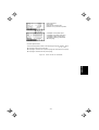
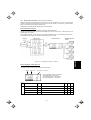
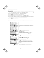
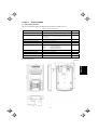
1.1 Acceptance Inspection
Unpack the package and check the following:
(1) The package contains a multi-function keypad and its
instruction manual (this book).
(2) There have been no problems during transportation. In
particular, no parts are damaged or have fallen out of place
nor are there any dents on the body.
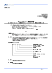
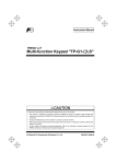
(3) The model name "TP-G1-J1" is inscribed on the back of the
multi-function keypad as shown in Figure 1.1.
The multi-function keypad is available in two models--"TP-G1-J1"
and "TP-G1-C1." The languages supported by those models differ
as listed below.
Model
Language
TP-G1-J1
English, Japanese, German, French, Spanish,
and Italian
TP-G1-C1
Chinese, Japanese, English, and Korean
If you suspect the product is not working properly or if you have
any questions about your product, contact your Fuji Electric
representative.
Figure 1.1
Back of Multi-function Keypad
TP-G1-J1
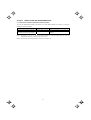
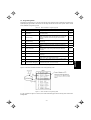
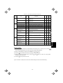
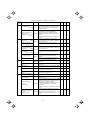
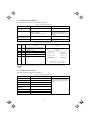
1.2 Inverters with which the Multi-function Keypad Interfaces
FRENIC series
FRENIC-Eco
Type of inverter *
Remarks
FRNF1S-
The multi-function keypad is fully supported by inverters with a ROM
version F1S10300 or later. (You can check the inverter’s ROM version
with [MAIN] in Menu #5 "Maintenance Information" in Programming
Mode.)
FRNF1E-
FRNF1H-
There are restrictions on the support for the multi-function keypad by
inverters with a ROM version earlier than F1S10300. For details,
consult your Fuji Electric representative.
FRENIC-Multi
FRNE1S-
FRNE1E-
FRENIC-MEGA
FRNG1S-
FRNG1E-
FRNG1H-
The multi-function keypad is fully supported by all of the FRENIC-Multi
series of inverters.
The multi-function keypad is fully supported by inverters with a ROM
version G1S10500 or later. (You can check the inverter’s ROM version
with [MAIN] in Menu #5 "Maintenance Information" in Programming
Mode.)
There are restrictions on the support for the multi-function keypad by
inverters with a ROM version earlier than G1S10500. For details,
consult your Fuji Electric representative.
* A box () replaces an alphanumeric character. For the details of the inverter type identification, refer to the inverter's
instruction manual, Chapter 1, Section 1.1 "Acceptance Inspection."
1-1
ENGLISH
The multi-function keypad "TP-G1-J1" interfaces with the following Fuji inverters:
Chapter 2
INSTALLATION AND INTERCONNECTION
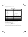
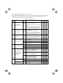
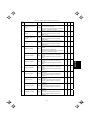
2.1 Accessories and Parts Required for Interconnection
To mount the multi-function keypad on the panel or any other device instead of an inverter, you need the
following accessories and parts.
Accessories/Parts
Type or Specifications
Remarks
Remote operation extension cable (Note 1)
CB-5S, CB-3S, or CB-1S
Choice of three lengths: 5 m, 3 m, and 1 m
Screws
(for mounting the multi-function keypad)
M3 × (Note 2)
Two screws required (to be provided by the
customer)
(Note 1) Alternatively, you can use an off-the-shelf 10BASE-T/100BASE-TX LAN cable (straight type) that meets the
ANSI/TIA/EIA-568A Category 5 standard (maximum length: 20 m).
(Note 2) Use the screws of the length just right for the panel. (See Figure 2.6.)
2-1
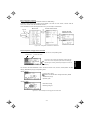
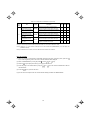
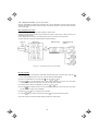
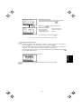
2.2 Mounting the Multi-function Keypad
2.2.1
Three ways of installation/use
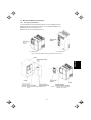
You can install and/or use the multi-function keypad in one of the following three ways:
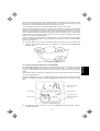
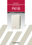
Mounting it directly on the inverter (see Figure 2.1). (For FRENIC-Eco/MEGA only.)
Mounting it on the panel (see Figure 2.2).
Using it remotely in your hand (see Figure 2.3).
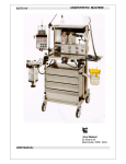
(a)
FRN15F1S-2J
(b)
FRN37F1S-2J
ENGLISH
Figure 2.1 Mounting the Multi-function Keypad Directly on the Inverter
Figure 2.2
Mounting the Multi-function Keypad on the
Panel
Figure 2.3
2-2
Using the Multi-function Keypad
Remotely in Your Hand
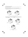
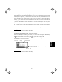
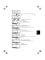
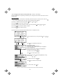
2.2.2
Mounting the multi-function keypad
After completion of interconnection, mount the multi-function keypad using the following procedure. Be sure to
turn the inverter power OFF beforehand.
Mounting the multi-function keypad directly on the inverter (For FRENIC-Eco/MEGA only)
(1) If a remote keypad is mounted on the inverter, remove it by pulling it toward you with the hook held down as
directed by the arrows in Figure 2.4.
Figure 2.4
Removing the Remote Keypad
(2) Put the multi-function keypad in the original slot while engaging its bottom latches with the holes (as shown
below), and push it onto the case of the inverter (arrow ) while holding it downward (against the terminal
block cover) (arrow ).
Figure 2.5
Mounting the Multi-function Keypad
2-3
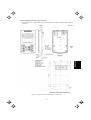
Mounting the multi-function keypad on the panel
ENGLISH
(1) Cut the panel out for a single square area and perforate two screw holes on the panel wall as shown in
Figure 2.6.
Figure 2.6
Location of Screw Holes and Dimension of Panel Cutout
2-4
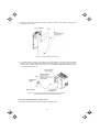
(2) Mount the multi-function keypad on the panel wall with 2 screws as shown below. (Recommended
tightening torque: 0.7 N•m)
Figure 2.7
Mounting the Multi-function Keypad
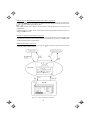
(3) If a remote keypad is mounted on the inverter, remove it (see Figure 2.4) and, using a remote operation
extension cable or a LAN cable, interconnect the multi-function keypad and the inverter (insert one end of
the cable into the RS-485 port with RJ-45 connector on the multi-function keypad and the other end into that
on the inverter) (See Figure 2.8).
Figure 2.8
Connecting the Multi-function Keypad to the Inverter with Remote
Operation Extension Cable or an Off-the-shelf LAN Cable
Using the multi-function keypad remotely in hand
Follow step (3) of "Mounting the multi-function keypad on the panel" above.
2-5
Chapter 3
OPERATION USING THE MULTI-FUNCTION KEYPAD
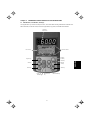
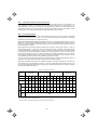
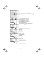
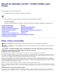
3.1 LED Monitor, LCD Monitor, and Keys
The keypad allows you to start and stop the motor, view various data including maintenance information and
alarm information, set function codes, monitor I/O signal status, copy data, and calculate the load factor.
7-segment
LED monitor
LCD monitor
Indicator indexes
LED lamp
Shift key
RUN key
(reverse)
STOP key
Reset key
UP key
DOWN key
Remote/Local
key
3-1
Function/Data key
ENGLISH
RUN key
(forward)
Program key
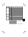
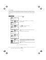
Table 3.1
Item
Overview of Keypad Functions
Monitors and Keys
Functions
Five-digit, 7-segment LED monitor which displays the following according to the
operation modes:
In Running mode:
In Programming mode:
In Alarm mode:
Running status information (e.g., output frequency,
current, and voltage)
same as above
Alarm code, which identifies the cause of alarm if the
protective function is activated.
LCD monitor which displays the following according to the operation modes:
Monitors
In Running mode:
In Programming mode:
In Alarm mode:
Indicator indexes
Running status information
Menus, function codes and their data
Alarm code, which identifies the cause of an alarm if
the protective function is activated.
In Running mode, these indexes show the unit of the number displayed on the
7-segment LED monitor and the running status information on the LCD monitor.
For details, see the next page.
Switches the operation modes of the inverter.
Shifts the cursor to the right when entering a number.
Pressing this key after removing the cause of an alarm will switch the inverter to
Running mode.
This key is used to reset settings or screen transition.
Programming keys
and
UP and DOWN keys. These keys are used to select the setting items or change
the function code data.
Function/Data key. This key switches the operation mode as follows:
In Running mode:
In Programming mode:
In Alarm mode:
Pressing this key switches the information to be
displayed concerning the status of the inverter (output
frequency (Hz), output current (A), output voltage (V),
etc.).
Pressing this key displays the function code and
establishes the newly entered data.
Pressing this key displays the details of the problem
indicated by the alarm code that has appeared on the
LED monitor.
Starts running the motor (forward rotation).
Starts running the motor (reverse rotation).
Operation
keys
Stops the motor.
Holding down this key for more than 1 second toggles between local and remote
modes.
LED
lamp
Lights while a run command is supplied to the inverter.
3-2
Indicator Index details
Unit of number
on LED monitor
Running status
Item
Hz
Output frequency and frequency command
A
Output current
V
Output voltage
%
Calculated torque, load factor, and speed
r/min
Preset and actual motor speeds and preset and actual load shaft speeds
m/min
Preset and actual line speeds
kW
Input power and motor output
X10
Data exceeding 99,999
min
Preset and actual constant feeding rate times
sec
Timer
PID
PID process value
FWD
Running in forward rotation
REV
Running in reverse rotation
STOP
No output frequency
REM
Remote mode
LOC
Run command
source
Description (information, condition, status)
COMM
JOG
HAND
Local mode
Via communication (RS-485 (standard, optional), field bus option)
Jogging mode
Via keypad (This item lights also in local mode.)
3-3
ENGLISH
Type
3.2 Overview of Operation Modes
The FRENIC series of inverters feature three operation modes listed in Table 3.2.
Table 3.2 Operation Modes
Mode
Description
This mode allows you to enter run/stop commands in regular operation. You can also
monitor the running status in real time.
If a light alarm occurs, the l-al* appears on the LED monitor. (Only in FRENIC-MEGA)
This mode allows you to set function code data and check a variety of information relating
to the inverter status and maintenance.
If an alarm condition arises, the inverter automatically enters the Alarm mode. In this mode,
you can view the corresponding alarm code* and its related information on the LED and
LCD monitors.
Running Mode
Programming Mode
Alarm Mode
* Codes that represent the causes of alarms that have been triggered by the protective
function. For details, refer to "Protective Functions" in the inverter's instruction manual.
Figures 3.1 (a) and (b) show the status transition of the inverter between these three operation modes.
Figure 3.1 (a)
Status Transition between Operation Modes in FRENIC-Eco/Multi
Power ON
Running mode
Programming mode
Run/Stop of motor
Monitor of running status
or
Detection of
a light alarm
Configuration of function
code data and monitor of
maintenance/alarm info
and various status
Release of
a light alarm
Run/Stop of motor
Light alarm displayed
(Press this key if
an alarm has
occurred.)
Occurrence of
a heavy alarm
Release of
a heavy alarm
Alarm mode
Display of alarm status
Figure 3.1 (b)
Status Transition between Operation Modes in FRENIC-MEGA (With light alarm added.)
3-4
3.3 Running Mode
When the inverter is turned ON, it automatically enters Running mode in which you can:
[ 1 ] Configure the frequency command and PID commands
[ 2 ] Run or stop the motor,
[ 3 ] Monitor the running status (e.g., output frequency, output current),
[ 4 ] Jog (inch) the motor,
[ 5 ] Switch between the remote and local modes, and
[ 6 ] Monitor light alarms.
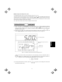
3.3.1
Configuring the frequency command and PID commands
You can configure the frequency command and PID commands with the
and
keys on the keypad.
It is possible to display or configure the reference frequency as load shaft speed and other
converted values of the mechanical system with function code E48. To configure the reference
frequency while monitoring the motor speed, load shaft speed, or speed (%), set the E48 data to 3,
4, or 7, respectively, as listed in Table 3.8 "Items Monitored."
■ Configuring the frequency command
Using
and
keys (F01 = 0 (factory default) or 8)
(1) Set function code F01 at "0" or "8" (
/
keys on keypad). This cannot be done when the keypad is in
and
keys, first place the
Programming mode or Alarm mode. To enable frequency setting using the
keypad in Running mode.
The lowest digit blinks.
Means the keypad takes precedence.
Allowable entry range
Operation guide
Figure 3.2 Example of Frequency Command Configuring Screen
(3) To change the frequency command, press the
inverter’s internal memory.
or
3-5
key again. The new setting can be saved into the
ENGLISH
(2) Press the
or
key. The 7-segment LED monitor displays the frequency command and the LCD
monitor displays the related information including the operation guide, as shown in Figure 3.2.
• The frequency command setting will be saved either automatically by turning the main power OFF
key. You can choose either way using function code E64. (Available in
or only by pressing the
FRENIC-Eco/MEGA)
• When you start accessing the frequency command or any other parameter with the
and
keys, the lowest digit on the display will blink and start changing. As you are holding down the key,
blinking will gradually move to the upper digit places and the upper digits will be changeable.
• Pressing the
key moves the changeable digit place (blinking) and thus allows you to change
upper digits easily.
• By setting function code C30 at "0" (Enable
/
keys on the keypad) and selecting frequency
command 2 as a frequency command source, you can also access the frequency command in the
same manner using the
and
keys.
/
keys on keypad) but have selected a frequency
• If you have set function code F01 at "0" (
command source other than frequency 1 (i.e., frequency 2, via communications, or as a
or
key for changing the frequency command
multi-frequency), then you cannot use the
even if the keypad is in Running mode. Pressing either of these keys will just display the currently
selected frequency command.
/
keys on keypad) enables the balanceless-bumpless
• Setting function code F01 at "8" (
switching. When the frequency command source is switched to the keypad from any other source,
the inverter inherits the current frequency that has applied before switching, providing smooth
switching and shockless running. (Available in FRENIC-MEGA)
• When the frequency command source is other than the digital reference setting, the LCD monitor
displays the following.
Means that the keypad is not
enabled.
Means that the setting on the
analog terminal [12] is effective.
(See Table 3.3.)
Table 3.3 lists the available command sources and their symbols.
Table 3.3
Symbol
Command source
Symbol
HAND
Keypad
MULTI
12
Terminal [12]
C1
Terminal [C1]
RS485-1
12 + C1
Terminal [12] +
Terminal [C1]
V2
U/D
Available Command Sources
Command source
Multi-frequency
Symbol
Command source
PID-HAND
PID keypad command
PID-P1
PID command 1
(Analog command)
RS-485 (Port 1) *1
PID-P2
PID command 2
(Analog command)
RS485-2
RS-485 (Port 2) *2
PID-U/D
PID UP/DOWN
command
Terminal [V2]
BUS
Bus option
PID_LINK
PID communications
command
UP/DOWN control
LOADER
Inverter support software
"FRENIC loader"
PID+MULTI
PID multi-frequency
command
*1 Refers to COM port 1 which is the RJ-45 connector on the inverter.
*2 Refers to COM port 2 which is on the terminal block of the inverter (FRENIC-MEGA) or on that of the option card
(FRENIC-Eco/Multi).
3-6
■ Make settings under PID process control
To enable PID process control, you need to set function code J01 at "1" or "2."
and
keys are different from those under
Under the PID control, the items that can be accessed with the
regular frequency control, depending upon the current LED monitor setting. If the LED monitor is set to the
speed monitor, the item accessible is a manual speed command (frequency command); if it is set to any other
data, the item accessible is a PID process command.
Refer to the inverter's user's manual for details on the PID control.
Configuring the PID process command with the
(1) Set function code J02 at "0" (
/
and
keys
keys on keypad).
(2) Set the LED monitor to something other than the speed monitor (E43 = 0) while the keypad is in Running
and
keys while the keypad is in
mode. You cannot modify the PID process command with the
and
keys,
Programming mode or Alarm mode. To enable the modification of the command with the
first switch to Running mode.
(3) Press the
or
key. The 7-segment LED monitor displays the PID process command and the LCD
monitor displays the related information including the operation guide, as shown in Figure 3.3.
Means that the keypad command is
effective.
Allowable range
Operation guide
Figure 3.3 Example of PID Process Command Configuring Screen
On the LED monitor, the decimal point of the lowest digit is used to characterize what is
displayed. The decimal point of the lowest digit blinks when a PID process command is
displayed; the decimal point lights when a PID feedback amount is displayed.
(4) To change the PID process command, press the
the inverter’s internal memory.
or
3-7
key again. The new setting can be saved into
ENGLISH
The lowest digit blinks.
• The PID process command will be saved either automatically by turning the main power OFF or
only by pressing the
key. You can choose either way using function code E64. (Available in
FRENIC-Eco/MEGA)
• Even if multi-frequency is selected as a PID process command (SS4 or SS8 = ON), you still can
set the process command using the keypad.
or
key displays,
• When function code J02 is set to any value other than "0," pressing the
on the LED monitor, the PID process command currently selected, while you cannot change the
setting. The LCD monitor displays the following.
Means that PID process
command 1 (analog
command) is effective.
Table 3.4 PID Process Command Manually Set with
PID control
(Mode
selection)
J01
PID control
(Remote command SV)
J02
LED Monitor
E43
Multifrequency
SS4, SS8
Other than 0
ON or OFF
0
1 or 2
and
Keys and Requirements
With
and
keys
PID process command by keypad
Other than 0
PID process command currently selected
Configuring the frequency command with the
and
keys under PID control
/
keys on keypad) and frequency command 1 (Frequency setting
When function code F01 is set at "0" (
via communications link: Disabled; Multi-frequency setting: Disabled; PID control: Disabled) is selected as a
keys if you specify the
and
manual speed command, you can modify the frequency setting using the
LED monitor as the speed monitor while the keypad is in Running mode.
Note that you cannot modify the frequency setting using the
keys while the keypad is in
and
Programming mode or Alarm mode. To enable the modification of the frequency setting using the
and
keys, first switch to Running mode. These conditions are summarized in Table 3.5 and the figure below. Table
3.5 shows the combinations of the parameters, while the figure below illustrates how the manual speed
entered via the keypad is translated to the final frequency command .
command
The setting and viewing procedures are the same as those for usual frequency setting.
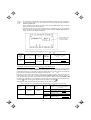
Table 3.5 Speed (Frequency) Command Manually Specified with
Frequency
command 1
(F01)
0
Frequency setting
via communications
link
Disabled
Other than the above
Multi-frequency
setting
Disabled
PID control
disabled
and
Keys and Requirements
Display during
/
key operation
PID enabled
PID output (as final frequency command)
Disabled
Manual speed command by keypad
(frequency setting)
PID enabled
PID output (as final frequency command)
Disabled
Manual speed command currently selected
(frequency setting)
3-8
■ Make settings under PID dancer control
To enable the PID dancer control, you need to set function code J01 at "3."
keys are different from those under
and
Under the PID control, the items that can be accessed with the
the regular frequency control, depending upon the current LED monitor setting. If the LED monitor is set to the
speed monitor, the item accessible is a primary frequency command; if it is set to any other data, the item
accessible is a PID dancer position command.
Configuring the PID dancer position command with the
(1) Set function code J02 at "0" (
/
and
keys
keys on keypad).
(2) Set the LED monitor to something other than the speed monitor (E43 = 0) when the inverter is in Running
mode. You cannot modify the PID dancer position command with the
keys while the keypad is
and
in Programming mode or Alarm mode. To enable the modification of the command, first switch to Running
mode.
The lowest digit blinks.
Means that the keypad command is
effective.
Allowable range
Operation guide
Figure 3.4 Example of PID Dancer Position Command Configuring Screen
On the LED monitor, the decimal point of the lowest digit is used to characterize what is
displayed. The decimal point of the lowest digit blinks when a PID dancer position command is
displayed; the decimal point lights when a PID feedback amount is displayed.
3-9
ENGLISH
or
key. The 7-segment LED monitor displays the PID dancer position command and the
(3) Press the
LCD monitor displays the related information including the operation guide, as shown in Figure 3.4.
key again. The new setting can be
(4) To change the PID dancer position command, press the
or
saved into the inverter’s internal memory as function code J57 data. It is retained even if you temporarily
switch to another PID command source and then go back to the via-keypad PID command. Furthermore,
you can directly configure the command with function code J57.
• Even if multi-frequency is selected as a PID dancer position command (SS4 or SS8 = ON),
you still can set the command using the keypad.
key
• When function code J02 is set to any value other than "0," pressing the
or
displays, on the LED monitor, the PID dancer position command currently selected, while
you cannot change the setting. The LCD monitor displays the same as for the PID process
control.
Table 3.6 Primary Frequency Command Specified with
PID control
(Mode
selection)
J01
PID control
(Remote command SV)
J02
and
LED Monitor
E43
Multi-frequency
SS4, SS8
Other than 0
ON or OFF
0
3
Keys and Requirements
With
and
keys
PID command by keypad
Other than 0
PID command currently selected
Configuring the primary frequency command with the
and
keys under PID dancer control
keys on keypad) and frequency command 1 (Frequency setting
When function code F01 is set at "0" (
/
via communications link: Disabled; Multi-frequency setting: Disabled) is selected as a primary frequency
command, you can modify the primary frequency command using the
and
keys if you specify the LED
monitor as the speed monitor while the keypad is in Running mode.
and
keys while the keypad is in
Note that you cannot modify the primary frequency command using the
Programming mode or Alarm mode. To enable the modification of the frequency setting, first switch to Running
entered via the keypad is translated to
mode. The figure below shows how the primary frequency command
the final frequency command .
The setting procedure is the same as that for usual frequency setting.
3-10
3.3.2
Running or stopping the motor
key starts running the motor in the forward direction and pressing the
By factory default, pressing the
key is disabled. You can run or stop the motor using the keypad only
key decelerates the motor to stop. The
in Running mode and Programming mode.
To run the motor in reverse direction or to run the motor in reversible mode, change the setting of function code
F02.
For details of function code F02, refer to the inverter's instruction manual, Chapter 5 "FUNCTION
CODES."
Figure 3.5 Rotational Direction of Motor
Note) The rotational direction of IEC-compliant motor is opposite to the one shown above.
■ Displaying the running status on the LCD monitor
(1) When function code E45 (LCD monitor item selection) is set at "0"
The LCD monitor displays the running status, the rotational direction, and the operation guide.
(The lower indicators show the running status and run command source. For the upper ones, see Section
3.3.3.)
Running status
ENGLISH
Rotational direction
Operation guide
Figure 3.6
Display of Running Status
The running status and the rotational direction are displayed as listed in Table 3.7.
Table 3.7
Status/Direction
Running Status and Rotational Direction
Display
Meaning
Running status
RUN
STOP
A run command is present or the inverter is driving the motor.
A run command is not present and the inverter is stopped.
Rotational direction
FWD
REV
Blank
Forward rotation being commanded.
Reverse rotation being commanded.
The inverter is stopped.
(2) When function code E45 (LCD monitor item selection) is set at "1"
The LCD monitor displays the output frequency, output current, and calculated torque in a bar chart.
(The lower indicators show the running status and run command source. For the upper ones, see Section
3.3.3.)
3-11
Output frequency
Bar chart
Output current
Calculated torque
The full scale (maximum value) for each parameter is as follows:
Output frequency: Maximum frequency
Output current:
200% of inverter’s rated current
Calculated torque: 200% of rated torque generated by motor
Figure 3.7
3.3.3
Bar Chart
Monitoring the running status on the LED monitor
The items listed below can be monitored on the 7-segment LED monitor. Immediately after the power is turned
ON, the monitor item specified by function code E43 is displayed.
Pressing the
key in Running mode switches between monitor items in the sequence shown in Table 3.8.
The "Monitor page #" column shows the monitor page of items supported by each inverter model.
Table 3.8
Monitored Items on
the LED Monitor
Speed Monitor
Example
Unit
Items Monitored
Meaning of Displayed Value
Function code E48 specifies what to be displayed.
Function
code E43
Eco
Multi MEGA
0
Output frequency
(before slip
compensation)
5*00
Hz
Frequency actually being output (Hz)
(E48=0)
Output frequency
(after slip
compensation)
5*00
Hz
Frequency actually being output (Hz)
(E48=1)
Reference
frequency
5*00
Hz
Frequency actually being output (Hz)
(E48=2)
Motor speed
1500
r/min
Output frequency (Hz) ×
Load shaft speed
30*0
r/min
Output frequency (Hz) x E50
(E48=4)
Line speed
30*0
r/min
Output frequency (Hz) x E50
(E48=5)
Constant feeding
rate time
Monitor page #
0
120
P01
E50
(E48=3)
Some items are not
displayed depending
on the inverter
model. For details,
refer to the inverter's
instruction manual.
50
min
5*0
%
Output frequency (Hz)
× 100
Maximum frequency (Hz)
Output current
1"34
A
Output of the inverter in current in rms
3
8
Input Power
1*25
kW
Input power to the inverter
9
9
%
Motor output torque in % (Calculated
value)
8
10
Speed (%)
Calculated torque
50
Output frequency (Hz) x E39
3-12
(E48=6)
(E48=7)
Monitored Items on
the LED Monitor
Example
Unit
Output voltage
200
V
Motor output
)85
Items Monitored (Continued)
Meaning of Displayed Value
Function
code E43
Monitor page #
Eco
Multi MEGA
Output of the inverter in voltage in rms
4
11
kW
Motor output in kW
16
12
50
%
Load rate of the motor in % with the
rated output being at 100%
15
13
PID command
(Note 1)
1*0*
-
PID command/feedback amount
transformed to that of physical value of
the object to be controlled.
10
14
PID feedback amount
(Note 1)
)0*
-
Refer to the function codes E40 and E41
for details.
12
15
10**
%
PID output in % with the maximum
output frequency (F03) being at 100%
14
16
Analog input monitor
(Note 2)
8"00
-
Timer
(for timer operation)
(Note 3)
50
s
Current position pulse
100
Position deviation
pulse
Load factor
PID output
(Note 1)
Analog input to the inverter converted
per E40 and E41
17
18
-
18
Remaining time when the timer
operation is enabled
13
-
17
-
pulse
Current position pulse for use under
positioning control
21
-
19
-
100
pulse
Position deviation pulse for use under
positioning control
22
-
20
-
Torque current
(Note 4)
48
%
Torque current command value or
calculated torque current
23
-
-
21
Exciting current
magnetic flux
command
(Note 4)
50
%
Magnetic flux command value
24
-
-
22
10*0
kWh
Input watt - hour (kWh)
100
25
-
-
23
Input watt-hour
Refer to the function codes E40 and E41
for details.
The LCD monitor (given below) shows information related to the item shown on the LED monitor. The monitor
item on the LED monitor can be switched by pressing the
key.
Monitor page #
(See Table 3.8.)
Item to be monitored
Operation guide
Figure 3.8 LCD Monitor Sample Detailed for the LED Monitor Item
(Note 1) These PID related items appear only when the inverter drives the motor under the PID control specified by
function code J01 (= 1, 2 or 3). When a PID command or PID output is displayed, the dot at the lowest digit on
the LED monitor blinks; when a PID feedback amount is displayed, it is lit.
(Note 2) This item appears only when the analog input monitor is enabled by any of function codes E61 to E63 (Select
terminal function).
(Note 3) This item appears only when the timer operation is enabled by function code C21 (data = 1).
(Note 4) If the V/f control is selected, a zero (0) is displayed.
3-13
ENGLISH
Table 3.8
3.3.4
Jogging (inching) the motor (Available in FRENIC-Multi/MEGA)
To start jogging operation, perform the following procedure.
(1) Make the inverter ready to jog with the steps below.
1) Switch the inverter to Running mode (see Section 3.2).
2) Press the "
+
keys" simultaneously. The lower indicator above the "JOG" index comes ON.
• Function code C20 specifies the jogging frequency. H54 and H55 (H55 is available only in
FRENIC-MEGA) specify the acceleration and deceleration times, respectively. These three
function codes are exclusive to jogging operation. Specify each function code data, if needed.
• Using the input terminal command "Ready for jogging" JOG switches between the normal
operation state and ready-to-jog state.
• Switching between the normal operation state and ready-to-jog state with the "
keys" is possible only when the inverter is stopped.
+
(2) Jog the motor.
While the
or
motor to stop.
key is held down, the motor continues jogging. Releasing the key decelerates the
(3) Make the inverter exit from the ready-to-jog state and return to the normal operation state.
Press the "
3.3.5
+
keys" simultaneously. The lower indicator above the "JOG" index goes OFF.
Switching between the remote and local modes (Available in FRENIC-Eco/MEGA)
The inverter can be operated either in remote mode or in local mode. In remote mode, which applies to normal
operation, the inverter is driven under the control of the data settings held in it, whereas in local mode, which
applies to maintenance operation, it is separated from the system and is driven manually under the control of
the keypad.
• Remote mode: The run and speed command sources are determined by source switching signals including
function codes, run command 2/1 switching signal, and communications link operation signal.
The keypad cannot be used as a command source.
• Local mode:
The keypad is enabled as a run and speed command source, regardless of the settings
specified by function codes. The keypad takes precedence over run command 2/1 switching
signal, communications link operation signal or other command sources.
The table below lists the run command sources using the keypad in the local mode.
Table 3.9 Run Commands from the Keypad in the Local Mode
Data for F02
0: Keypad
Run command sources
You can run or stop the motor using the
,
, and
keys on the keypad.
1: External signal
2: Keypad (forward)
You can run or stop the motor using the
and
You can run the motor in forward direction only. (The
3: Keypad (reverse)
You can run or stop the motor using the
and
You can run the motor in reverse direction only. (The
Holding down the
keys on the keypad.
key is disabled.)
keys on the keypad.
key is disabled.)
key for at least one second switches between the remote and local modes.
3-14
The mode can be switched also by an external digital input signal. To enable the switching, you need to assign
LOC to one of the digital input terminals, which means that the commands from the keypad are given
precedence (one of function codes E01 to E09, E98, or E99 must be set to "35").
You can confirm the current mode on the indicators (REM: Remote mode; LOC: Local mode).
When the mode is switched from Remote to Local, the frequency settings in the remote mode are automatically
inherited. Further, if the inverter is in Running mode at the time of the switching from Remote to Local, the run
command is automatically turned ON so that all the necessary data settings will be carried over. If, however,
there is a discrepancy between the settings on the keypad and those in the inverter itself (e.g., switching from
reverse rotation in the remote mode to forward rotation in the local mode using the keypad that is for forward
rotation only), the inverter automatically stops.
The paths of transition between remote and local modes depend on the current mode and the value (ON/OFF)
of LOC, the signal giving precedence to the commands from the keypad, as shown in the state transition
diagram shown in Figure 3.9.
For further details on how to set run commands and frequency commands in remote and local modes,
refer to the drive command related section in the inverter's user's manual, "BLOCK DIAGRAMS FOR
CONTROL LOGIC."
Figure 3.9 Transition between Remote and Local Modes
Monitoring light alarms (Available only in FRENIC-MEGA)
The FRENIC-MEGA identifies abnormal states in two categories--Heavy alarm and Light alarm. If the former
occurs, the inverter immediately trips; if the latter occurs, the inverter shows the l-al on the LED monitor and
blinks the "L-ALARM" indication in the operation guide area on the LCD monitor but it continues to run without
tripping.
Which abnormal states are categorized as a light alarm ("Light alarm" object) should be defined with function
codes H81 and H82 beforehand.
Assigning the LALM signal to any one of the digital output terminals with any of function codes E20 to E24 and
E27 (data = 98) enables the inverter to output the LALM signal on that terminal upon occurrence of a light
alarm.
Means that a light alarm
has occurred.
Rotational direction
Running status
Indicator indexes
Operation guides
Means that a light alarm
has occurred.
Figure 3.10 Display of Light Alarm
For details of the light alarm factors, refer to the FRENIC-MEGA Instruction Manual, Chapter 6
"TROUBLESHOOTING."
3-15
ENGLISH
3.3.6
■ How to check a light alarm factor
If a light alarm occurs, l-al appears on the LED monitor. To check the current light alarm factor, enter
key and select LALM1 on Menu #5 "Maintenance Information." For
Programming mode by pressing the
details of the menu transition of the maintenance information, refer to Section 3.4.6 "Reading maintenance
information."
It is also possible to check the factors of the last three light alarms by selecting LALM2 (last) to LALM4 (3rd
last).
■ How to remove the current light alarm
After checking the current light alarm factor, to switch the LED monitor from the l-al indication state back to
key in Running mode.
the running status display (e.g., output frequency), press the
If the light alarm factor has been removed, the "L-ALARM" disappears and the LALM output signal turns OFF. If
not (e.g. DC fan lock), the l-al on the LED monitor disappears (normal monitoring becomes available), the
"L-ALARM" remains displayed on the LCD monitor, and the LALM output signal remains ON.
The l-al has
disappeared and the
normal LED monitor is
displayed.
Rotational direction
Running status
Indicator indexes
Operation guides
The operation guides
remain displayed.
3-16
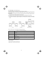
3.4 Programming Mode
Programming mode allows you to set and check function code data and monitor maintenance information and
input/output (I/O) signal status. The functions can be easily selected with a menu-driven system. Table 3.10 lists
menus available in Programming mode.
0
Menus Available in Programming Mode
Menu
Main functions
Refer to:
Quick Setup
Displays only basic function codes pre-selected.
3.4.2
1
Data Setting
Allows you to view and change the setting of the function code
you select. (Note)
3.4.1
2
Data Checking
Allows you to view and change a function code and its setting
(data) on the same screen. Also this allows you to check the
function codes that have been changed from their factory
defaults.
3.4.3
3
Drive Monitoring
Displays the running information required for maintenance or
test running.
3.4.4
4
I/O Checking
Displays external interface information.
3.4.5
5
Maintenance Information
Displays maintenance information including cumulative run
time.
3.4.6
6
Alarm Information
Displays four latest alarm codes. Also this allows you to view
the information on the running status at the time the alarm
occurred.
3.4.7
7
Alarm Cause
Displays the cause of the alarm.
3.4.8
8
Data Copying
Allows you to read or write function code data, as well as
verifying it.
3.4.9
9
Load Factor Measurement
Allows you to measure the maximum output current, average
output current, and average braking power.
3.4.10
10
User Setting
Allows you to add or delete function codes covered by Quick
Setup.
3.4.11
11
Communication Debugging
Allows you to confirm the data of function codes for
communication (S, M, W, X, and Z codes).
3.4.12
(Note) The o codes for options appear only when the corresponding option(s) is mounted on the inverter.
Figure 3.11 shows the transitions between menus in Programming mode.
Figure 3.11
Menu Transition in Programming Mode
If no key is pressed for approx. 5 minutes, the inverter automatically goes back to Running mode and turns the
backlight OFF.
3-17
ENGLISH
Table 3.10
Menu #
3.4.1
Setting function codes
-- Menu #1 "Data Setting" --
Menu #1 "Data Setting" in Programming mode allows you to set function codes for making the inverter functions
match your needs.
The function codes available differ depending upon the inverter model.
Table 3.11 Function Code List
Function Code Group
Function
F code
(Fundamental functions)
Fundamental functions
Functions concerning basic motor running
Terminal functions
Functions concerning the selection of operation of the
control circuit terminals; Functions concerning the
display on the LED monitor
C code
(Control functions of
frequency)
Control functions
Functions associated with frequency settings
P code
(Motor 1 parameters)
Motor 1 parameters
Functions for setting up characteristics parameters
(such as capacity) of the 1st motor
H code
(High performance functions)
High-level functions
Highly
added-value
sophisticated control
A code
(Motor 2 parameters)
Motor 2 parameters
Functions for setting up characteristics parameters
(such as capacity) of the 2nd motor
b code
(Motor 3 parameters)
Motor 3 parameters
Functions for setting up characteristics parameters
(such as capacity) of the 3rd motor
r code
(Motor 4 parameters)
Motor 4 parameters
Functions for setting up characteristics parameters
(such as capacity) of the 4th motor
J code
(Application functions 1)
Application functions 1
Functions for applications such as PID control
J code
(Application functions 2)
Application functions 2
Functions for applications such as speed control
Link functions
Functions for controlling communications
Optional functions
Functions for optional features (Note)
E code
(Extension terminal functions)
y code
(Link functions)
o code
(Option functions)
Description
functions;
Functions
for
(Note) The o codes appear only when the corresponding option(s) is mounted on the inverter.
Function codes requiring simultaneous keying
To modify the data for function code F00 (data protection), H03 (data initialization), or H97 (clear alarm data),
simultaneous keying of "
keys" or "
+
+
keys" is required.
Changing, validating, and saving function code data when the invert is running
Some function codes can be modified while the inverter is running, whereas others cannot. Further, depending
on the function code, modifications may or may not become effective immediately. For details, refer to the
"Change when running" column in Section 5.1 "Function Code Tables" in Chapter 5 of the inverter's instruction
manual.
3-18
Basic configuration of screens
Figure 3.12 shows the LCD screen transition for Menu #1 "Data Setting."
A hierarchy exists among those screens that are shifted in the order of "menu screen," "function code list
screen," and "function code data modification screens."
On the modification screen of the target function code, you can modify or check its data.
Menu screen
Function code list screen
Function code data
modification screens
Figure 3.12 Configuration of Screens for "DATA SET"
Screen samples for changing function code data
The "function code list screen" shows function codes, their names, and operation guides.
Function code name
The function code currently selected blinks, indicating that the
cursor has moved to this position (F03 blinks in this example).
Operation guide, scrolling horizontally to display the function of
each key.
The "function code data modification screen" shows the function code, its name, its data (before and after
change), allowable entry range, and operation guides.
<Before change>
Function code #, name
: Function code that has been changed from factory default
Data
Allowable entry range
Operation guide
<Changing data>
Data before change
Data being changed
Figure 3.13 Screen Samples for Changing Function Code Data
3-19
ENGLISH
Function code
Basic key operation
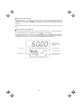
This section will give a description of the basic key operation, following the example of the function code data
changing procedure shown in Figure 3.14.
This example shows you how to change function code F03 data (maximum frequency) from 58.0 Hz to 58.1 Hz.
(1) When the inverter is powered ON, it automatically enters Running mode. In Running mode, press the
key to enter Programming mode. The menu for function selection will be displayed.
(2) Using the
and
keys, move the pointer Æ to "1. DATA SET" and then press the
display a list of function codes.
key, which will
(3) Use the
and
keys to select the desired function code group (in this example, F03:), and press the
key, which will display the screen for changing the desired function code data.
(4) Change the function code data by using the
and
keys. Pressing the
digit place to shift (cursor shifting) (The blinking digit can be changed).
(5) Press the
key causes the blinking
key to establish the function code data.
The data will be saved in the memory inside the inverter. The display will return to the function code list, then
move to the next function code (in this example, F04).
If you press the
key before the
key, the change made to data of the function code is cancelled. The
data reverts to the previous value, the screen returns to the function code list, and the function code (F03)
reappears.
(6) Press the
key to go back to the menu from the function code list.
/
/
/
Select the desired menu by moving the pointer Æ with
key.
Press
key to establish the desired menu.
Press
key to go back to Menu.
Select desired function code by moving the cursor with
/
key.
Press
key to establish the desired function code.
Press
/
key to change function code data.
Press
key to establish the function code data.
Press
key to cancel change of data.
Figure 3.14 Changing Function Code Data
3-20
/
3.4.2
Setting up function codes quickly using Quick Setup -- Menu #0 "Quick Setup" --
Menu #0 "QUICK SET" in Programming mode allows you to quickly set up a fundamental set of function codes
that you specify beforehand. Whereas at shipment from factory, only a set of function codes predetermined as
quick setup items is registered, you can add or delete some function codes using "10. USER SET." The set of
function codes covered by Quick Setup is held in the inverter (not the keypad). Therefore, if you mount your
keypad onto another inverter, the set of function codes held in the new inverter is subject to Quick Setup. If
necessary, you may copy the set of function codes subject to Quick Setup using the copy function (Menu #8
"Data Copying").
If you perform data initialization (function code H03), the set of function codes subject to Quick Setup will be
reset to the factory default.
For the list of function codes subject to Quick Setup by factory default, refer to the inverter's instruction
manual, Chapter 5 "FUNCTION CODES."
The LCD screen transition from Menu #0 is the same as with Menu #1 "Data Setting."
Basic key operation
Same as the basic key operation for Menu #1 "Data Setting."
3.4.3
Checking changed function codes -- Menu #2 "Data Checking" --
Menu #2 "Data Checking" in Programming mode allows you to check function codes (together with their data)
that have been changed. The function codes whose data have been changed from factory defaults are marked
key, you can view or change its data.
with . By selecting a function code and pressing the
The LCD screen transition from Menu #2 is the same as with Menu #1 "Data Setting," except for the different
screen listing function codes as shown below.
Changed
Function code data
ENGLISH
Function code
Operation guide, scrolling horizontally to display the
function of each key.
Figure 3.15 Function Code List Screen
Basic key operation
Same as the basic key operation for Menu #1 "Data Setting."
3-21
3.4.4
Monitoring the running status -- Menu #3 "Drive Monitoring" --
Menu #3 "Drive Monitoring" in Programming mode allows you to check the running status during maintenance
and test running.
Available function codes differ depending on the inverter model.
Table 3.12 Drive Monitoring Display Items
Page #
in ope.
guide
1
Item
Multi MEGA
Fot1
Output frequency (before slip compensation)
√
√
√
Fot2
Output frequency (after slip compensation)
-
√
√
Output current
Iout
Output current
√
√
√
Output voltage
Vout
Output voltage
√
√
√
Calculated torque
TRQ
Calculated output torque generated by motor
√
√
√
Fref
FWD
REV
(Blank)
Frequency command
√
√
√
Forward
Reverse
Stopped
√
√
√
Current limit
IL
Current limiting
√
√
√
Undervoltage
Voltage limit
LU
VL
Undervoltage detected
Voltage limiting
√
√
√
Torque limit
TL
Torque limiting
-
√
√
Speed limit
SL
RL
Speed limiting
Rotation direction limiting
-
-
√
Motor selected
M1-M4
Motor 1 to 4
-
-
√
Drive control
VF
DTV
VF-SC
VC-SL
VC-PG
V/f control without slip compensation
Dynamic torque vector control
V/f control with slip compensation
Vector control without speed sensor
Vector control with speed sensor
-
-
√
Motor speed
SYN
√
√
√
Load shaft speed
LOD
Output frequency (Hz) × Function code E50
√
√
√
Line speed
LIN
Output frequency (Hz) × Function code E50
√
√
√
LSC
Actual peripheral speed under constant
peripheral speed control
-
-
√
√
√
√
√
√
√
√
√
√
Constant peripheral
speed control monitor
4
Eco
Output frequency
Running direction
3
Description
Output frequency
Frequency command
2
Symbol
PID command
SV
PID feedback amount
PV
(Output frequency Hz) ×
120
P01
The PID command and PID feedback amount
are displayed after conversion to the virtual
physical values (e.g., temperature or pressure)
of the object to be controlled using the function
code E40 and E41 data (PID display
coefficients A and B).
Display value = (PID command or feedback
amount) × (Coefficient A - B) + B
PID output value
MV
PID output value, displayed in % (assuming the
maximum frequency (F03) as 100%).
3-22
Table 3.12 Drive Monitoring Display Items (Continued)
5
6
Item
8
Description
Eco
Multi MEGA
Torque limit value A
TLA
Driving torque limit value A (based on motor
rated torque)
-
√
√
Torque limit value B
TLB
Driving torque limit value B (based on motor
rated torque)
-
√
√
Reference torque bias
TRQB
Reserved ("----" appears.)
-
-
-
Current position pulse
P
Current position pulse for positioning control
-
√
√
Stop position target pulse
E
Stop position target pulse for positioning control
-
√
√
dP
Position deviation pulse for positioning control
-
√
√
Positioning control status
-
√
√
Position deviation pulse
Positioning control status
7
Symbol
MODE
Motor temperature
NTC
Temperature detected by the NTC thermistor
built in the motor (VG motor)
-
-
√
Ratio setting
Rati
When this setting is 100%, the LED monitor
shows 1.00.
-
-
√
-
-
√
-
-
√
-
-
√
-
-
√
-
-
√
-
-
√
Magnetic flux command
value
FLUX
Deviation in SY
synchronous operation
SY-d
4-multiplied current
position pulse
P4
4-multiplied stop position
target pulse
E4
4-multiplied position
deviation pulse
dP4
Positioning control status
MODE
Flux command value in %.
Deviation in SY synchronous operation
Current position pulse for positioning control
Stop position target pulse for positioning control
Position deviation pulse for positioning control
Positioning control status
Basic key operation
(1) When the inverter is powered ON, it automatically enters Running mode. In Running mode, press the
key to enter Programming mode. The menu for function selection will be displayed.
(2) Select "3. OPR MNTR" by moving the pointer Æ with the
(3) Press the
keys.
key to display the screen (by one page) for Operation Monitor.
(4) Select the page for the desired item by using the
information for the desired item.
(5) Press the
and
and
keys and confirm the running status
key to go back to the menu.
Figure 3.16 shows an example of the LCD screen transition starting from Menu #3 "Drive Monitoring."
3-23
ENGLISH
Page #
in ope.
guide
/
Select desired menu by moving the pointer Æ with
key.
key to establish the desired menu.
Press
Output frequency (before slip compensation)
Output frequency (after slip compensation)
Output current
Output voltage
1/8: Page # in operation guide
/
T means that this page continues to the next page.
Calculated torque
Frequency command
Running status
(See Table 3.12.)
/
Motor speed
Load shaft speed
Line speed
Constant peripheral speed control monitor
/
PID command
PID feedback amount
PID output value
/
Torque limit value A
Torque limit value B
Reserved.
/
Current position pulse
Stop position target pulse
Position deviation pulse
Positioning control status
/
3-24
/
Motor temperature
Ratio setting
Magnetic flux command value
Deviation in SY synchronous operation
/
4-multiplied current position pulse
4-multiplied stop position target pulse
4-multiplied position deviation pulse
4-multiplied positioning control status
S: End of page
Common operation items
To access the target data, switch to the desired page using the
and
keys.
T: This page continues to the next page.
¡: This page is continued from the previous page and continues to the next page.
S: This page is continued from the previous page.
ENGLISH
Figure 3.16 Screen Transition for "OPR MNTR"
3-25
3.4.5
Checking I/O signal status -- Menu #4 "I/O Checking" --
Menu #4 "I/O CHECK" in Programming mode allows you to check the digital and analog input/output signals
coming in/out of the inverter. This menu is used to check the running status during maintenance or test run.
Available function codes differ depending on the inverter model.
Table 3.13
Page #
in ope.
guide
1
2
Item
Input signals at the
control circuit terminal
block
Input signals via
communications link
Symbol
Description
Eco
FWD,
REV, X1
- X9, EN
Shows the ON/OFF state of the input signals at
the control circuit terminal block.
(Highlighted when short-circuited; normal when
open)
√
√
√
√
√
√
Note) The number of applicable terminals differs
depending on the inverter model. For details,
refer to the inverter's instruction manual.
√
√
√
Di
Input signal at the control circuit terminal block
(in hexadecimal)
√
√
√
Do
Output signal (in hexadecimal)
√
√
√
Input signal via communications link
(hexadecimal)
√
√
√
12
Input voltage at terminal [12]
√
√
√
C1
Input current at terminal [C1]
√
√
√
Note)
FWD,
REV, X1
- X9, XF,
XR, RST
Note)
3
Output signals
Y1 - Y4,
Y5,
30ABC
Note)
4
I/O signals (hexadecimal)
LNK
5
Analog input signals
V2
Analog output signals
6
7
Note) Symbols and
output formats differ
depending on the
inverter model.
I/O signals of digital input
and output interface cards
(option)
Pulse train input
I/O Check Items
Multi MEGA
Note) The number of applicable terminals differs
depending on the inverter model. For details,
refer to the inverter's instruction manual.
Input information for function code S06
(communication)
(Highlighted when 1; normal when 0)
Note) The number of applicable terminals differs
depending on the inverter model. For details,
refer to the inverter's instruction manual.
Output signal information
Input voltage at terminal [V2]
√
√
√
FMA
FMA
FMP
FMP
Output voltage at terminal [FMA]
Output current at terminal [FMA]
Average output voltage at terminal [FMP]
Pulse rate at terminal [FMP]
√*
√
√*
FMA
FMA
FMI
Output voltage at terminal [FMA]
Output current at terminal [FMA]
Output current at terminal [FMI]
√*
-
-
FM1
FM1
FM2
FM2
Output voltage at terminal [FM1]
Output current at terminal [FM1]
Output voltage at terminal [FM2]
Output current at terminal [FM2]
-
-
√*
Di-o
Input signal of option card in hexadecimal
-
√
√
Do-o
Output signal of option card in hexadecimal
-
√
√
Pulse count signal of pulse train input at
terminal [X7]
-
-
√
X7
* Some screens differ depending upon the specifications even on the same inverter models.
3-26
Table 3.13 I/O Check Items (Continued)
Page #
in ope.
guide
8
9
Item
Symbol
Eco
Multi MEGA
P1
Pulse rate (p/s) of the A/B phase signal fed
back from the reference PG
-
√
√
Z1
Pulse rate (p/s) of the Z phase signal fed back
from the reference PG
-
√
√
P2
Pulse rate (p/s) of the A/B phase signal fed
back from the slave PG
-
√
√
Z2
Pulse rate (p/s) of the Z phase signal fed back
from the slave PG
-
√
√
32
Input voltage at terminal [32] (option)
-
-
√
C2
Input current at terminal [C2] (option)
-
-
√
A0
Output voltage at terminal [A0] (option)
-
-
√
CS
Output current at terminal [CS] (option)
-
-
√
PG pulse rate
I/O signals of analog
input/output interface
cards
(option)
Description
Basic key operation
(1) When the inverter is powered ON, it automatically enters Running mode. In Running mode, press the
key to enter Programming mode. The menu for function selection will be displayed.
(2) Select "4. I/O CHECK" by moving Æ with the
key to display the screen (by one page) for I/O Checking.
and
(4) Select the page for the desired item by using the
desired item.
(5) Press the
keys.
keys and confirm the I/O check data for the
key to go back to the menu.
Figure 3.17 shows an example of the LCD screen transition starting from Menu #4 "I/O Checking."
3-27
ENGLISH
(3) Press the
and
/
Select the desired menu by moving the pointer Æ with
key.
Press
/
key to establish the desired menu.
Input signals at the control circuit terminal block
Highlighted when short-circuited
Normal when open
Note: The number of applicable terminals differs depending on
the inverter model.
/
Input signals via communications link
(See Note 1 on page 3-30.)
Highlighted when 1
Normal when 0
Note: The number of applicable terminals differs depending on
the inverter model.
/
Output signals
Highlighted when ON
Normal when OFF
Note: The number of applicable terminals differs depending on
the inverter model.
/
I/O signals (hexadecimal) (See Note 2 on page 3-30.)
Input signals at the control circuit terminal block
Output signal
Input signals via communications link (See Note 1 on page
3-30.)
/
Analog input signals
Input voltage at terminal [12]
Input current at terminal [C1]
Input voltage at terminal [V2]
/
Analog output signals*
Output voltage at terminal [FMA]
Output current at terminal [FMA]
Average output voltage at terminal [FMP]
Pulse rate at terminal [FMP]
/
* Some screens differ depending upon the specifications even on
the same inverter models. (See Table 3.13.)
3-28
I/O signals (option) (in hex.)
(See Note 2 on the next page.)
Input signal
Output signal
Pulse rate signal
/
PG pulse rate (option)
A/B phase signal from reference PG
Z phase signal from reference PG
A/B phase signal from slave PG
Z phase signal from slave PG
/
Analog I/O signals (option)
Input voltage at terminal [32]
Input current at terminal [C2]
Output voltage at terminal [A0]
Output current at terminal [CS]
Common operation items
To access the target data, switch to the desired page using the
and
keys.
T: This page continues to the next page.
¡: This page is continued from the previous page and continues to the next page.
Figure 3.17 Screen Transition for "I/O CHECK"
3-29
ENGLISH
S: This page is continued from the previous page.
Note 1 Input status at terminals via communications link
Input commands sent via RS-485 communications or other communications options can be displayed in two
ways depending on setting of the function code S06: "Display with ON/OFF of the LED segment" or "In
hexadecimal format." The content to be displayed is basically the same as that for the control I/O signal terminal
status display; however, (XF), (XR), and (RST) are added as inputs. Note that under communications control,
I/O display is in normal logic (Active-ON) (using the original signals that are not inverted).
Note 2 I/O status (hexadecimal)
Each I/O terminal is assigned to one of the 16 binary bits (bit 0 through bit 15). The bit to which no I/O terminal
is assigned is considered to have a value of "0." The I/O status is thus collectively expressed as a four-digit,
hexadecimal number (0 through F) as shown in Table 3.14.
Digital input terminals [FWD] and [[REV] are assigned to bits 0 and 1, [X1] through [X9] to bits 2 through 10, and
[EN] to bit 11, respectively. Each bit assumes a value of "1" when the corresponding signal is ON and a value of
"0" when it is OFF. For example, when signals [FWD] and [X1] are ON while all the other signals are OFF, the
status is expressed as "0005H."
Digital output terminals [Y1] through [Y4] are assigned to bits 0 through 3. Each is given a value of "1" when it is
short-circuited to [CMY], or a value of "0" when its circuit to [CMY] is open. The status of relay output terminal
[Y5A/C] is assigned to bit 4, which assumes a value of "1" when the contact between [Y5A] and [Y5C] is closed.
The status of relay output terminal [30A/B/C] is assigned to bit 8, which assumes a value of "1" when the contact
between [30A] and [30C] is closed or "0" when the contact between [30B] and [30C] is closed. For example,
when terminal [Y1] is ON, terminals [Y2] through [Y4]] are OFF, the contact between [Y5A] and [Y5C] is opened,
and the link between 30A and 30C is closed, the status is expressed as "0101H."
As in the control I/O signal terminal status display, the ON/OFF status of each input/output terminal signal of a
digital input and output interface cards (option) is expressed in hexadecimal notation.
Digital input terminals [I1] through [I16] on a digital input interface card (option) are assigned to 16 binary bits
(bit 0 through bit 15). Each bit assumes a value of "1" when the corresponding signal is ON and a value of "0"
when it is OFF. Digital output terminals [O1] through [O8] on a digital output interface card (option) are assigned
to eight binary bits (bit 0 through bit 7).
Table 3.14 Hexadecimal Notation
Data
Displayed
Bit
Highest digit
15
14
*
13
*
*
Input signal (RST) (XR) (XF)
Option
12
11
10
9
8
7
6
5
-
[EN]
[X9]
4
3
[X8]
[X7]
[X6]
[X5]
-
2
1
0
[X4]
[X3]
[X2]
[X1] [REV] [FWD]
-
-
[Y5A
/C]
[Y4]
[Y3]
[Y2]
[Y1]
-
-
-
-
-
-
-
[30A/B
/C]
DI
[I16]
[I15]
[I14]
[I13]
[I12]
[I11]
[I10]
[I9]
[I8]
[I7]
[I6]
[I5]
[I4]
[I3]
[I2]
[I1]
DO
-
-
-
-
-
-
-
-
[O8]
[O7]
[O6]
[O5]
[O4]
[O3]
[O2]
[O1]
Binary
0
0
0
0
0
0
0
0
0
0
0
0
0
1
0
1
Output signal
Example
(input)
Lowest digit
0005H
Hex
-: unassigned
* (XF), (XR), (RST) are for communications.
Refer to "Note 1 Input status at terminals via communications link" above.
3-30
3.4.6
Reading maintenance information -- Menu #5 "Maintenance Information" --
Menu #5 "MAINTENANC" in Programming mode allows you to view information necessary for performing
maintenance on the inverter.
Available function codes differ depending on the inverter model.
Table 3.15
Page #
in ope.
guide
Item
Display Items for Maintenance
Symbol
Description
Eco
Multi MEGA
Shows the cumulative run time during which the
inverter was powered ON.
1
√
√
√
Shows the DC link bus voltage of the inverter’s
main circuit.
√
√
√
TMPI
Shows a maximum temperature inside the inerter
every hour.
√
-
√
Max. temperature of heat
sink
TMPF
Shows the maximum temperature of the heat sink
every hour.
√
√
√
Max. effective current
Imax
Shows the maximum current in rms every hour.
√
√
√
CAP
Shows the current capacitance of the DC link bus
capacitor as % of the capacitance at factory
shipment. Refer to the inverter's instruction
manual, Chapter 7 "MAINTENANCE AND
INSPECTION" for details.
√
√
√
√
√
√
-
-
√
√
√
√
√
√
√
NST
Shows the total count of startups of the motor
(count of times when the run command for the
inverter was turned ON). When the total time
exceeds 65,535 hours, the counter will be reset to
0 and the count will start again.
√
√
√
Wh
Shows the input watt-hours of the inverter. Upon
exceeding 1,000,000 kWh, the count goes back to
0.
√
√
√
Cumulative run time
TIME
DC link bus voltage
EDC
Max. temperature inside
the inverter
Capacitance of the DC link
bus capacitor
When the total time exceeds 65,535 hours, the
counter will be reset to 0 and the count will start
again.
Cumulative motor run time
MTIM
When the count exceeds 65,535 hours
(FRENIC-Eco/Multi) or 99,990 hours
(FRENIC-MEGA), the counter will be reset to 0
and the count will start again.
Remaining time before the
Shows the time remaining before the next
next maintenance for
maintenance, which is estimated by subtracting
REMT1
motor 1
the cumulative run time of motor 1 from the
Note 1)
maintenance interval specified by H78.
Cumulative run time of
electrolytic capacitor on
the printed circuit board
Shows the product of the cumulative time of
voltage being applied to the electrolytic capacitor
on the printed circuit board and a coefficient
determined by the environmental condition.
TCAP
A time to be used as a guide for replacement
timing of the capacitor is indicated in brackets.
For details, refer to the inverter's instruction
manual, Chapter 7 "MAINTENANCE
INSPECTION."
3
Cumulative run time of the
cooling fan
Shows the cumulative run time of the cooling fan.
This counter does not work when the cooling fan
ON/OFF control (function code H06) is enabled
and the fan stops.
TFAN
A time to be used as a guide for replacement
timing of the cooling fan is indicated in brackets.
For details, refer to the inverter's instruction
manual, Chapter 7 "MAINTENANCE
INSPECTION."
Count of startups
Note 1)
4
Input watt-hour
Note 2)
3-31
ENGLISH
Shows the cumulative run time of the motor.
2
Table 3.15 Display Items for Maintenance (Continued)
Page #
in ope.
guide
4
Item
Symbol
Description
Eco
Input watt-hour data
Note 2)
PD
Shows the input watt-hour data as input watt-hour
(kWh) x function code E51. (The range of display
is 0.001 to 9,999. Values exceeding 9,999 are
expressed as 9,999.)
√
√
√
-
-
√
√
√
√
√
√
√
√
√
√
√
√
√
Shows the cumulative count of errors detected
during optional communication with option
installed.
√
√
-
Option error code
Shows the latest error that has been detected
during optional communication in a code.
√
√
-
ROM version of the
inverter
MAIN
Shows the ROM version of the inverter as a
4-digit code.
√
√
√
ROM version of the
keypad
KP
Shows the ROM version of the keypad as a
4-digit code.
√
√
√
OP1
Shows the ROM version of the option connected
to the A-port as a 4-digit code.
√
√
√
ROM version of
option 2
OP2
Shows the ROM version of the option connected
to the B-port as a 4-digit code.
-
-
√
ROM version of
option 3
OP3
Shows the ROM version of the option connected
to the C-port as a 4-digit code.
-
-
√
Shows the current temperature inside the inverter.
-
-
√
-
-
√
-
-
√
-
-
√
Remaining startup times
before the next
maintenance for motor 1
Note 1)
Shows the start-up times remaining before the
next maintenance, which is estimated by
subtracting the number of start-ups from the
REMN1 preset start-up count for maintenance specified
by H79.
The display method is the same as for REMT1
above.
Count of RS-485 errors
(COM port 1)
Note 3)
RS-485 error content
(COM port 1)
Note 3), Note 4)
5
NRR1
Count of RS-485 errors
(COM port 2)
Note 3)
RS-485 error content
(COM port 2)
Note 3), Note 4)
NRR2
Count of option errors
NRO
6
ROM version of
option 1
7
8
Multi MEGA
Shows the total number of errors that have
occurred in RS-485 communication (COM port 1)
since first power ON.
Shows the latest error that has occurred in
RS-485 communication (COM port 1) in a code.
Shows the total number of errors that have
occurred in RS-485 communication (COM port 2)
since first power ON.
Shows the latest error that has occurred in
RS-485 communication (COM port 2) in a code.
Temperature inside the
inverter (real-time value)
TMPIM
Temperature of heat sink
(real-time value)
Shows the current temperature of the heat sink
TMPFM
inside the inverter.
Lifetime of DC link bus
capacitor
(elapsed hours)
Shows the cumulative time during which a voltage
is applied to the DC link bus capacitor. When the
main power is shut down, the inverter
automatically measures the discharging time of
CAPEH the DC link bus capacitor and corrects the
elapsed time.
The display method is the same as that for TCAP
above.
Lifetime of DC link bus
capacitor
(remaining hours)
Shows the remaining lifetime of the DC link bus
capacitor, which is estimated by subtracting the
CAPRH elapsed time from the lifetime (10 years).
The display method is the same as that for TCAP
above.
3-32
Table 3.15 Display Items for Maintenance (Continued)
Item
Symbol
Cumulative run time of
motor 1
MTIM1
Cumulative run time of
motor 2
MTIM2
Cumulative run time of
motor 3
MTIM3
Cumulative run time of
motor 4
Number of startups 2
Number of startups 4
Light alarm (Latest)
Light alarm (Last)
√
-
-
√
Shows the content of the cumulative power-ON
time counter of the 3rd motor.
The display method is the same as that for
MTIM1 above.
-
-
√
MTIM4
Shows the content of the cumulative power-ON
time counter of the 4th motor.
The display method is the same as that for
MTIM1 above.
-
-
√
NST1
Shows the content of the 1st motor startup
counter (i.e., the number of run commands
issued).
Counter range: 0 to 65,535 times
When the count exceeds 65,535, the counter will
be reset to "0" and start over again.
-
-
√
NST2
Shows the content of the 2nd motor startup
counter (i.e., the number of run commands
issued).
The display method is the same as for NST1
above.
-
-
√
NST3
Shows the content of the 3rd motor startup
counter (i.e., the number of run commands
issued).
The display method is the same as for NST1
above.
-
-
√
NST4
Shows the content of the 4th motor startup
counter (i.e., the number of run commands
issued).
The display method is the same as for NST1
above.
-
-
√
LALM1
Shows the factor of the latest light alarm as an
alarm code.
For details, refer to the inverter's instruction
manual, Chapter 6, Section 6.1 "Protective
Functions."
-
-
√
LALM2
Shows the factor of the last light alarm as an
alarm code.
For details, refer to the inverter's instruction
manual, Chapter 6, Section 6.1 "Protective
Functions."
-
-
√
LALM3
Shows the factor of the 2nd last light alarm as an
alarm code.
For details, refer to the inverter's instruction
manual, Chapter 6, Section 6.1 "Protective
Functions."
-
-
√
LALM4
Shows the factor of the 3rd last light alarm as an
alarm code.
For details, refer to the inverter's instruction
manual, Chapter 6, Section 6.1 "Protective
Functions."
-
-
√
11
Light alarm (2nd last)
Light alarm (3rd last)
Multi MEGA
-
10
Number of startups 3
Shows the content of the cumulative power-ON
time counter of the 1st motor.
Eco
-
9
Number of startups
Description
When the count exceeds 99,990, the counter will
be reset to "0" and start over again.
Shows the content of the cumulative power-ON
time counter of the 2nd motor.
The display method is the same as that for
MTIM1 above.
3-33
ENGLISH
Page #
in ope.
guide
Table 3.15 Display Items for Maintenance (Continued)
Page #
in ope.
guide
Item
Count of option 1
communications errors
Option 1 communications
error code
12
Count of option 2
communications errors
Option 2 communications
error code
Count of option 3
communications errors
Option 3 communications
error code
Symbol
NROA
NROB
NROC
Description
Eco
Multi MEGA
Shows the total number of errors that have
occurred in the option connected to the A-port.
-
-
√
Shows the code of the error that has occurred in
the option connected to the A-port.
-
-
√
Shows the total number of errors that have
occurred in the option connected to the B-port.
-
-
√
Shows the code of the error that has occurred in
the option connected to the B-port.
-
-
√
Shows the total number of errors that have
occurred in the option connected to the C-port.
-
-
√
Shows the code of the error that has occurred in
the option connected to the C-port.
-
-
√
Note 1) Available for the 1st motor only even if the inverter has the motor switching function.
Note 2) To reset the input watt-hour and input watt-hour data to 0, set function code E51 to "0.000."
Note 3) "COM port 1" is on the inverter; "COM port 2" is on the terminal block (FRENIC-MEGA) or on the option card
(FRENIC-Eco/Multi).
Note 4) For details of error contents, refer to the RS-485 Communication User’s Manual.
Basic key operation
(1) When the inverter is powered ON, it automatically enters Running mode. In Running mode, press the
key to enter Programming mode. The menu for function selection will be displayed.
(2) Select "5. MAINTENANC" by moving the pointer Æ with the
(3) Press the
keys.
key to display the screen (by one page) for Maintenance.
(4) Select the page for the desired item by using the
the desired item.
(5) Press the
and
and
keys and confirm the Maintenance data for
key to go back to the menu.
Figure 3.18 shows an example of the LCD screen transition starting from Menu #5 "MAINTENANC."
3-34
/
Select the desired menu by moving the pointer Æ with
key.
Press
/
key to establish the desired menu.
Cumulative run time
DC link bus voltage
Max. temperature inside the inverter
Max. temperature of heat sink
/
Max. effective current
Capacitance of the DC link bus capacitor
Cumulative motor run time
Remaining time before the next maintenance for motor 1
Cumulative run time of
electrolytic capacitor (reference)
Cumulative run time of the cooling fan (reference)
/
Number of startups
Input watt-hour
Input watt-hour data
Remaining start-up times before the next maintenance for
motor 1
/
Error count & content for COM port 1
Error count & content for COM port 2
Error count & error code for option communication
/
ROM version
ROM version of the inverter
ROM version of the keypad
/
3-35
ENGLISH
/
ROM version (option)
Option 1 (A-port)
Option 2 (B-port)
Option 3 (C-port)
/
Temperature inside the inverter
Temperature of the heat sink
Lifetime of DC link bus capacitor (elapsed hours)
Life time of DC link bus capacitor (remaining hours)
/
Cumulative run time of motor 1
Cumulative run time of motor 2
Cumulative run time of motor 3
Cumulative run time of motor 4
/
Number of startups
Number of startups 2
Number of startups 3
Number of startups 4
/
Light alarm (Latest)
Light alarm (Last)
Light alarm (2nd last)
Light alarm (3rd last)
/
Count of errors & error code
Option 1 (A-port)
Option 2 (B-port)
Option 3 (C-port)
Common operation items
To access the target data, switch to the desired page using the
and
keys.
T: This page continues to the next page.
¡: This page is continued from the previous page and continues to the next page.
S: This page is continued from the previous page.
Figure 3.18
Screen Transition for "MAINTENANC"
3-36
3.4.7
Reading alarm information -- Menu #6 "Alarm Information" --
Menu #6 "ALM INF" in Programming mode allows you to view the information on the four most recent alarm
conditions that triggered protective functions (in alarm code and the number of occurrences). It also shows the
status of the inverter when the alarm condition arose.
Available alarm information differs depending on the inverter model.
Basic configuration of screens
Figure 3.19 shows the LCD screen transition for Menu #6 "Alarm Information."
A hierarchy exists among those screens that are shifted in the order of "menu screen," "alarm list screen," and
"Detailed alarm info screens."
On the "alarm list screen," you can view the current alarm and alarm history; on the "detailed alarm info screen,"
the information on the inverter running status at the time the alarm occurred.
Menu screen
Alarm list screen
Detailed alarm info
screens
ENGLISH
Figure 3.19 Configuration of Screens for "ALM INF"
Screen samples for viewing alarm info
The alarm list screen shows the current alarm and alarm history.
Symbol
Alarm code
No. of alarm occurrences
Cause use (latest) & No. of occurrences
Cause (last) & No. of occurrences
Cause (2nd last) & No. of occurrences
Cause (3rd last) & No. of occurrences
Page #
in ope.
guide
-
Item
Symbol
Description
Eco
Multi MEGA
Alarm history (latest)
0/1
Alarm code and the number of occurrences
√
√
√
Alarm history (last)
-1
Alarm code and the number of occurrences
√
√
√
Alarm history (2nd last)
-2
Alarm code and the number of occurrences
√
√
√
Alarm code and the number of occurrences
√
√
√
Alarm history (3rd last)
-3
3-37
On the "detailed alarm info screen," you can view the information on the inverter running status at the time an
alarm occurred. Table 3.16 lists the alarm information displayed on the LCD monitor for "ALM INF."
Table 3.16 Alarm Information Displayed
Page #
in ope.
guide
1
Item
4
Eco
Multi MEGA
Fot1
Output frequency (before slip compensation)
√
√
√
Output current
Iout
Output current
√
√
√
Output voltage
Vout
Output voltage
√
√
√
Calculated torque
TRQ
Motor output torque
√
√
√
Frequency command
Fref
Frequency command
√
√
√
Forward
Reverse
Stopped
√
√
√
FWD
REV
(Blank)
Current limit
IL
Current limiting
√
√
√
Undervoltage
Voltage limit
LU
VL
Undervoltage detected
Voltage limiting
√
√
√
Torque limit
TL
Torque limiting
-
√
√
√
√
√
Speed limiting
Rotation direction limiting
-
-
√
Shows the cumulative power-ON time of the
inverter.
Cumulative run time
Speed limit
3
Description
Output frequency
Running direction
2
Symbol
TIME
SL
RL
When the total time exceeds 65,535 hours, the
display will be reset to 0 and the count will start
again.
Motor selected
M1-M4
Motor 1 to 4
-
-
√
Drive control
VF
DTV
VF-SC
VF-SL
VC-PG
V/f control without slip compensation
Dynamic torque vector control
V/f control with slip compensation
Vector control without speed sensor
Vector control with speed sensor
-
-
√
Number of startups
NST
Shows the cumulative count of times the motor
has been started (the inverter run command
has been issued). When the total count
exceeds 65,535, the display will be reset to 0
and the count will start again.
√
√
√
DC link bus voltage
EDC
Shows the DC link bus voltage of the inverter's
main circuit.
√
√
√
Temperature inside the
inverter
TMPI
Shows the temperature inside the inverter.
√
-
√
Max. temperature of
heat sink
TMPF
Shows the maximum temperature of the heat
sink.
√
√
√
√
√
√
Input signals at the
control circuit terminal
block
TRM
ON/OFF status of input signals of the terminals
[FWD], [REV], [X1] to [X9], [EN] (Highlighted
when short-circuited; normal when open)
Note) The number of applicable terminals
differs depending on the inverter model. For
detail, refer to the inverter's instruction manual.
3-38
Table 3.16 Alarm Information Displayed (Continued)
Page #
in ope.
guide
5
Item
Input signals via
communications link
Symbol
LNK
Description
ON/OFF status of input signals for function
code S06 (Communication).
[FWD], [REV], [X1] to [X9], (XF), (XR), (RST)
(Highlighted when 1; normal when o)
Eco
Multi MEGA
√
√
√
√
√
√
√
√
√
√
√
√
Secondary error code for the alarm.
√
√
√
Detected speed
-
-
√
Note) The number of applicable terminals
differs depending on the inverter model. For
details refer to the inverter's instruction manual.
Output signals to the terminals [Y1] to [Y4],
[Y5A/C], [30A/B/C]
6
7
Output signals
-
Overlapping alarm 1
3
Overlapping alarm 1
2
Error sub-code
SUB
Detected speed
SPEED
Note) The number of applicable terminals
differs depending on the inverter model. For
details, refer to the inverter's instruction manual.
Simultaneously occurring alarm codes (1)
("----" is displayed if no alarms have occurred.)
Simultaneously occurring alarm codes (2)
("----" is displayed if no alarms have occurred.)
Basic key operation
(1) When the inverter is powered ON, it automatically enters Running mode. In Running mode, press the
key to enter Programming mode. The menu for function selection will be displayed.
(2) Select "6. ALM INF" by moving the pointer Æ with the
and
keys.
(3) Press the
key to get the Alarm list screen, which displays information on the four most recent alarm
conditions (alarm code and the number of occurrences for each alarm condition).
(4) Select the alarm condition to be displayed, by using the
and
keys.
(5) Press the
key to display the alarm code on the LED Monitor and the screen (by one page) for the status
data at the time of the alarm on the LCD Monitor.
(6) Select the page for the desired item by using the
desired item.
(7) Press the
key to go back to the alarm list. Press the
and
keys and confirm the status data for the
key again to go back to the menu.
Figure 3.20 shows an example of the LCD screen transition starting from Menu #6 "Alarm Information."
3-39
ENGLISH
The information of the first alarm is saved as "Alarm history (last)" (Symbol: -1), and that of the latest
alarm is retained as " Alarm history (latest)" (Symbol: 0/1).
/
Select the desired menu by moving the pointer Æ with
key.
Press
/
key to establish the desired menu.
Alarm cause (latest) and no. of occurrences
Alarm cause (last) and no. of occurrences
Alarm cause (2nd last) and no. of occurrences
Alarm cause (3rd last) and no. of occurrences
key to go back to Menu.
Press
/
Select desired alarm for viewing the detailed information by
moving the cursor with
/
key.
Press
key to establish the desired alarm info.
Output frequency
Output current
Output voltage
Calculated torque
/
Frequency command
Running direction/status
Cumulative run time
Running status
(See Table 3.16)
/
Number of startups
DC link bus voltage
Temperature inside the inverter
Max. temperature of heat sink
/
Figure 3.20 Screen Transition for "ALM INF"
3-40
Input signals at the control circuit terminal block
Highlighted when short-circuited;
Normal when opened
Note: The number of applicable terminals differs depending on the
inverter model.
/
Input signals via communications link
Highlighted when 1;
Normal when 0
Note: The number of applicable terminals differs depending on the
inverter model.
/
Output signals
Highlighted when ON;
Normal when OFF
Note: The number of applicable terminals differs depending on the
inverter model.
/
Overlapping alarm 2
Overlapping alarm 1
Error sub-code
Detected speed
To access the target data, switch to the desired page using the
and
keys.
T: This page continues to the next page.
¡: This page is continued from the previous page and continues to the next page.
S: This page is continued from the previous page.
Figure 3.20 Screen Transition for "ALM INF" (Continued)
3-41
ENGLISH
Common operation items
3.4.8
Viewing cause of alarm -- Menu #7 "Alarm Cause" --
Menu #7 "ALM CAUSE" in Programming mode allows you to view the information on the four most recent alarm
conditions that triggered protective functions (in alarm code and the number of occurrences). It also shows the
cause of each alarm.
Basic configuration of screens
Figure 3.21 shows the LCD screen transition for Menu #7 "Alarm Cause."
A hierarchy exists among those screens that are shifted in the order of "menu screen," "alarm list screen," and
"detailed alarm code screens."
On the "detailed alarm code screen" of the target function code, you can view the cause of alarms.
The alarm list screen is the same as that for Menu #6 "Alarm Information."
Menu screen
Alarm list screen
Detailed alarm code
screens
Figure 3.21 Configuration of Screens for "ALM CAUSE"
Basic key operation
(1) When the inverter is powered ON, it automatically enters Running mode. In Running mode, press the
key to enter Programming mode. The menu for function selection will be displayed.
(2) Select "7. ALM CAUSEF" by moving the pointer Æ with the
and
keys.
key to get the Alarm list screen, which displays information on the four most recent alarm
(3) Press the
conditions (alarm code and the number of occurrences for each alarm condition).
(4) Select the alarm condition to be displayed, by using the
and
keys.
key to display the alarm code on the LED Monitor and the screen for the cause of the alarm
(5) Press the
(can be more than 1 page) on the LCD Monitor.
key to view the previous or next page.
(6) Press the
or
(7) Press the
key to go back to the alarm list. Press the
key again to go back to the menu.
Figure 3.22 shows the LCD screen transition starting from Menu #7 "Alarm Cause."
3-42
/
Select the desired menu by moving the pointer Æ with
key.
/
key to establish the desired menu.
Press
Alarm cause (latest) and no. of occurrences
Alarm cause (last) and no. of occurrences
Alarm cause (2nd last) and no. of occurrences
Alarm cause (3rd last) and no. of occurrences
key to go back to Menu.
Press
/
Press
key to establish the desired alarm cause page.
/
Press
key to go back to alarm list screen.
Press
/
key to check all alarm causes.
Alarm cause (2nd page)
Common operation items
To access the target data, switch to the desired page using the
and
keys.
T: This page continues to the next page.
¡: This page is continued from the previous page and continues to the next page.
S: This page is continued from the previous page.
Figure 3.22 Screen Transition for "ALM CAUSE"
3-43
ENGLISH
Alarm cause (1st page)
3.4.9
Data copying -- Menu #8 "Data Copying" --
Menu #8 "Data Copying" in Programming mode provides various copy functions.
The multi-function keypad can hold three sets of function code data in its internal memory so that it can be used
with three different inverters. The copy function includes "Read," "Write," and "Verify" functions, which can be
used as follows.
(a) Reading function code data out of an inverter for which function codes are already configured and then
writing such function code data altogether into another inverter.
(b) Copying the function code data saved in the inverter memory into the keypad memory for backup.
(c) Saving function code data in the multi-function keypad as master data--saving more than one set of function
code data in the multi-function keypad and writing a set of data suited to the machinery into the target
inverter.
(a) Copy
(b) Backup
(c) Data management
Table 3.17 lists the menu of copy function by the multi-function keypad.
Table 3.17 List of DATA COPY Operations
Operation
Description
Read: Read data
Reads out function code data from the inverter and stores it into the internal memory of
the keypad.
Write: Write data
Writes the data held in the selected memory area of the keypad into the inverter.
Verify: Verify data
Verifies the data held in the keypad’s internal memory against the function code data in
the inverter.
Check: Check data
Checks the model information (format) and function code data held in the three memory
areas of the keypad.
Protect: Protect data
Protects the function code data saved in the internal memory of the keypad, preventing
the data from overwrite.
Items that can be copied by this function are:
- Function code data
- Function code items subject to quick setup, and
- Digital frequency command and PID commands.
3-44
Basic configuration of screens
Figure 3.23 shows the LCD screen transition for Menu #8 "Data Copying."
A hierarchy exists among those screens that are shifted in the order of "menu screen," "copy function list
screen," and "data selection screen."
On the "data selection screen," you can select the target memory in the multi-function keypad and the desired
copy function to proceed.
Menu screen
Copy function list
screen
Data selection screen
ENGLISH
Figure 3.23 Configuration of Screens for "DATA COPY"
3-45
(1) Read operation
/
Select the desired menu by moving the pointer Æ with
key.
/
key to establish the desired menu.
Press
List of data copy operations
Select the desired operation by moving the cursor with
key.
Press
/
key to establish the desired operation.
Data selection screen
Select the desired data by moving the cursor with
key.
To go back to List of data copy operations, press
Press
/
key.
key to establish the desired data.
Confirmation screen
If "Read" is actually performed, the data read out from the
inverter will overwrite the data held in this memory area in the
key.
keypad. If OK, press
To go back to Data selection screen, press
key.
key to start Read operation.
Press
"In progress" screen
A bar indicating progress appears in the bottom.
Upon completion, Completion screen automatically appears.
Completion screen
Indicates that Read operation has completed successfully.
key.
To go back to List of data copy operations, press
Figure 3.24 Screen Transition for "READ"
3-46
If you press
/
key during Read operation, the
operation under way will be aborted, and this Error screen will
appear.(Note) Once aborted, all the data held in the keypad’s
memory would be deleted.
If a communication error is detected between the keypad and
the inverter, this Error screen will appear.
Figure 3.25 Error Screens for "READ"
ENGLISH
If an ERROR screen or an ERROR Ver. Screen appears during operation, press the
key to reset the
error condition. When Reset is complete, the screen will go back to List of data copy operations.
3-47
(2) Write operation
/
Select the desired menu by moving the pointer Æ with
key.
Press
/
key to establish the desired menu.
List of data copy operations
Select the desired operation by moving the cursor with
key.
Press
/
key to establish the desired operation.
Data selection screen
Select the desired data by moving the cursor with
key.
To go back to List of data copy operations, press
Press
/
key.
key to establish the desired data.
Confirmation screen
If "Write" is actually performed, the selected data will overwrite
the data held in the inverter. If OK, press
key.
To go back to Data selection screen, press
Press
key.
key to start Write operation.
"In progress" screen
A bar indicating progress appears in the bottom.
Upon completion, Completion screen automatically appears.
Completion screen
Indicates that Write operation has completed successfully.
key.
To go back to List of data copy operations, press
Figure 3.26 Screen Transition for "WRITE"
3-48
If you press
or
key during Write operation, the
operation under way will be aborted, and this Error screen will
appear.(Note) Updating of the function code data in the inverter
is incomplete, with some of it remaining old. Do not run the
inverter in this state. Before running the inverter, redo the
writing or perform initialization.
For safety considerations, the following situations are treated
as an error:
• No valid data is found in the keypad’s memory. (No Read
operation has been performed since factory shipment; or, a
Read operation has been cancelled or aborted.)
• The data held in the keypad’s memory has an error.
• There is a mismatch in inverter’s model number.
• A Write operation has been performed while the inverter is
running.
• The inverter is data-protected.
• The Write enable for keypad command WE-KP is OFF.
The function code data held in the keypad is incompatible with
that in the inverter. (Either data may be non-standard; or a
version upgrade performed in the past may have made the
keypad or the inverter incompatible. Contact your Fuji Electric
representative.)
Figure 3.27 Error Screens for "WRITE"
ENGLISH
If an ERROR screen or an ERROR Ver. Screen appears during operation, press the
key to reset
the error condition. When Reset is complete, the screen will go back to List of data copy operations.
3-49
(3) Verify operation
/
Select the desired menu by moving the pointer Æ with
key.
Press
/
key to establish the desired menu.
List of data copy operations
Select the desired operation by moving the cursor with
key.
Press
/
key to establish the desired operation.
Data selection screen
Select data to be verified by moving the cursor with
key.
To go back to List of data copy operations, press
Press
/
key.
key to establish the desired data.
Confirmation screen
If OK, press
key.
To go back to Data selection screen, press
Press
key.
key to start Verify operation.
"In progress" screen
A bar indicating progress appears in the bottom.
When a mismatch is found, the Verify operation is halted, with
the function code and its data displayed on the LCD Monitor.
To resume the Verify operation from the next function code,
press
key again.
To resume Verify, press
3-50
key.
"In progress" screen
A bar indicating progress appears in the bottom.
Upon completion, Completion screen automatically appears.
Completion screen
Indicates that Verify operation has completed successfully.
key.
To go back to List of data copy operations, press
Figure 3.28 Screen Transition for "VERIFY"
If you press
/
key during Verify operation, the
operation under way will be aborted, and this Error screen will
appear. (Note)
The function code data held in the keypad is incompatible with
that in the inverter. (Either data may be non-standard; or a
version upgrade performed in the past may have made the
keypad or the inverter incompatible. Contact your Fuji Electric
representative.)
Figure 3.29 Error Screen for "VERIFY"
If an ERROR screen or an ERROR Ver. Screen appears during operation, press the
key to reset
the error factor. When Reset is complete, the screen will go back to List of data copy operations.
3-51
ENGLISH
If the keypad does not have any valid data, this Error screen
will appear. (Note)
(4) Check operation
/
Select the desired menu by moving the pointer Æ with
key.
Press
/
key to establish the desired menu.
List of data copy operations
Select the desired operation by moving the cursor with
key.
/
key to establish the desired operation.
Press
Data selection screen
/
Select data to be checked by moving the cursor with
key.
To go back to List of data copy operations, press
key.
Press
key to establish the desired data.
"Check data" screen
Displays function codes and their data.
/
key.
To check other function codes, press
To go back to List of data copy operations, press
key.
Figure 3.30 Screen Transition for "DATA CHECK"
If no valid data is found in the keypad, this Error screen will
appear. (Note)
Figure 3.31 Error Screen for "DATA COPY"
If an ERROR screen appears during operation, press the
key to reset the error factor. When Reset
is complete, the screen will go back to List of data copy operations.
3-52
(5) Data protect operation
Perform the operation for function code protection on the "KPÅINV READ" screen.
Select the desired menu by moving the pointer Æ with
key.
/
key to establish the desired menu.
Press
List of data copy operations
Select the "KPÅINV READ" by moving the cursor with
key.
/
key to establish the desired operation.
Press
Data selection screen
Select the desired data by moving the cursor with
key.
To go back to List of data copy operations, press
Press
/
key.
key for more than five seconds.
Completion screen
The data number and inverter type are highlighted, which
indicates the selected data is protected.
key.
To go back to List of data copy operations, press
key for more than five seconds in the same procedure
(Note) To release the data protection, press the
shown above. The screen returns to the normal state (not highlighted), which indicates the selected data
is not protected.
Figure 3.32
Screen Transition for "DATA PROTECT"
In the process of DATA READ operation, selecting protected
causes the screen to display the
data and pressing the
"Protected" (indicating that the data cannot be copied) and
return to the normal state.
Figure 3.33 Warning Against Selecting Protected Data
3-53
ENGLISH
/
3.4.10 Measuring load factor -- Menu #9 "Load Factor Measurement" -Menu #9 "LOAD FCTR" in Programming mode allows you to measure the maximum output current, the average
output current, and the average braking power. There are two types of measurement modes as listed below.
Table 3.18 Measurement Modes
Measurement Mode
Description
Limited duration measurement mode
Measuring load factors for a limited duration (hours).
Start-to-stop measurement mode
Measuring load factors from the start to stop of running.
If the "start to stop" mode is entered while the inverter is running, the measurement takes place until it
is stopped. If the "start to stop" mode is entered while the inverter is stopped, the measurement will
take place from the next start of running until it is stopped.
( 1 ) Limited duration measurement mode
Basic key operation
(1) When the inverter is powered ON, it automatically enters Running mode. In Running mode, press the
key to enter Programming mode. The menu for function selection will be displayed.
(2) Select "9. LOAD FCTR" by moving the pointer Æ with the
(3) Press the
and
keys.
key to get the measurement mode selection screen.
(4) Select the "HOURS SET" mode by moving the pointer Æ with the
and
keys.
key to establish the measurement mode. Then specify the measurement duration (default: 1
(5) Press the
hour). For details, refer to the screen transition in Figure 3.34.
(6) Press the
key to start the measurement.
(7) Press the
key to go back to the menu.
Figure 3.34 shows an example of the LCD screen transition starting from Menu #9 "Load Factor Measurement."
3-54
/
Select the desired menu by moving the pointer Æ with
key.
/
key to establish the desired menu.
Press
Mode selection screen
Select the desired measurement mode by moving the cursor
with
/
key.
Press
key to establish the desired measurement mode.
Measurement duration specification (Default: 1 hour)
/
Set the duration by using
Press
,
, and
key.
keys.
key to establish the duration and start measurement.
Measurement in progress (remaining time displayed)
When the measurement is in progress, the remaining time is
displayed and counting down.
key during measurement forcibly terminates
Pressing the
the measurement.
When the measurement duration has elapsed, the
measurement stops with the results displayed.
Measurement complete
(The preset measurement duration
Max. output current
reverts to the default.)
Average output current
Average braking power
Figure 3.34 Screen Transition for "LOAD FCTR" (Limited duration measurement mode)
3-55
ENGLISH
To go back to Mode selection, press
( 2 ) Start-to-stop measurement mode
Basic key operation
(1) When the inverter is powered ON, it automatically enters Running mode. In Running mode, press the
key to enter Programming mode. The menu for function selection will be displayed.
(2) Select "9. LOAD FCTR" by moving the pointer Æ with the
(3) Press the
and
keys.
key to get the measurement mode selection screen.
(4) Select the "STARTÆSTOP" mode by moving the pointer Æ with the
and
keys.
key to establish the measurement mode. The start-to-stop measurement mode requires the
(5) Press the
entry of a run command. For details, refer to the screen transition in Figure 3.35.
(7) Press the
key to go back to the menu.
Figure 3.35 shows an example of the LCD screen transition starting from Menu #9 "Load Factor Measurement."
/
Select the desired menu by moving the pointer Æ with
key.
Press
/
key to establish the desired menu.
Mode selection screen
Select the desired measurement mode ("STARTÆSTOP" in
this example) by moving the cursor with
/
key.
Press
key to establish the desired measurement mode.
Confirmation screen
key.
If OK, press
To go back to Mode selection, press
key.
key to signal "Ready."
Press
Waiting for run command (Standby for measurement)
Upon receiving a run command, the measurement will start.
If a run command has already been received, this screen will
be skipped.
Run command
ON
Measurement will start upon receiving a run command.
3-56
Measurement in progress
The measurement will continue until the inverter is stopped.
key.
To discontinue the measurement, press
/
Pressing the
/
key stops the measurement.
Measurement complete
Max. output current
Average output current
Average braking power
(When the measurement
completes, the results are
displayed.)
To go back to Mode selection, press
key.
Figure 3.35 Screen Transition for "LOAD FCTR" ("STARTÆSTOP" mode)
Going back to Running mode
While the measurement of the load factor is in progress, you can go back to the running mode by
pressing the
key (or, to the Mode selection screen by pressing the
key).
In these cases, the measurement of the load factor will continue. You can go back to "9. LOAD FCTR"
and confirm, on the Mode selection screen, that the measurement is in progress.
After the measurement has ended, you can view the results of the measurement by pressing the
key on the Mode selection screen.
ENGLISH
Screen when the measurement is in progress
The results of the measurement will be deleted when the inverter is powered OFF.
3-57
3.4.11 Changing function codes covered by Quick setup -- Menu #10 "User Setting" -Menu #10 "USER SET" in Programming mode allows you to change the set of function codes that are covered
by Quick setup.
Basic key operation
(1) When the inverter is powered ON, it automatically enters Running mode. In Running mode, press the
key to enter Programming mode. The menu for function selection will be displayed.
(2) Select "10. USER SET" by moving the pointer Æ with the
(3) Press the
and
keys.
key to get the list of function codes.
(4) Select the function codes to be added or deleted, by moving the pointer Æ with the
(5) Press the
key to perform the addition or deletion.
(6) Press the
key to go back to the menu.
and
keys.
Figure 3.36 shows the LCD screen transition starting from the "10. USER SET" menu.
/
Select the desired menu by moving the pointer Æ with
key.
Press
/
key to establish the desired menu.
List of function codes
Lists function codes with their names.
The function codes covered by Quick setup are highlighted
(names are highlighted).
Select the function code to be added (not highlighted) by
/
key.
moving the cursor with
To go back to the menu, press
Press
key.
key to add it to Quick setup.
Select the function code to be deleted (highlighted) by moving
/
key.
the cursor with
To go back to the menu, press
Press
key.
key to delete it from Quick setup.
To go back to Menu, press
key.
Figure 3.36 Screen Transition for Changing Function Codes Covered by Quick Setup
3-58
3.4.12 Performing communication debugging -- Menu #11 "Communication Debugging" -Menu #11 "Communication Debugging" in Programming mode allows you to view the data of
communication-related function codes (S, M, W, X, and Z codes) to help debug programs for communication
with host equipment.
Basic key operation
(1) When the inverter is powered ON, it automatically enters Running mode. In Running mode, press the
key to enter Programming mode. The menu for function selection will be displayed.
(2) Select "11. COMM DEBUG" by moving the pointer Æ with the
(3) Press the
and
keys.
key to get the list of communication-related function codes.
(4) Select the function code, by moving the pointer Æ with the
(5) Press the
key to check or change the function code.
(6) Press the
key to go back to the menu.
and
keys.
Figure 3.37 shows the LCD screen transition starting from the "11. COMM DEBUG" menu.
Select the desired menu by moving the pointer Æ with
key.
key to establish the desired menu.
Press
List of communication-related function codes
Lists function codes with their names.
Select the function by moving the cursor with
/
To go back to the menu, press
key.
Press
S Code
/
ENGLISH
/
key.
key to establish the desired menu.
Function code # and name
( : Data exists (≠ 0))
Data
Range
Operation guide
Data can be changed by
/
key.
pressing
Function code # and name
Reference only (Cannot be
changed)
M, W, X, Z Code (Monitoring only)
Data
Operation guide
Figure 3.37 Screen Transition for Communication Debugging
3-59
3.5 Alarm Mode
When a protective function is triggered, resulting in an alarm, the inverter automatically enters the alarm mode,
displaying the alarm code on the LED Monitor and the details of the alarm on the LCD Monitor as shown below.
Most recent cause; No. of consecutive occurrences
Cause of alarm
Operation guide
Operation guide
appears.
If there is other alarm cause information,
Figure 3.38 Without Non-overlapping Alarm
If more than one alarm (overlapping alarm) occurs, the display appears as shown below. You can check the
overlapping alarms.
Overlapping alarm
If overlapping alarms occur, the most recent cause appears as "1 = alarm code," not as "0 = alarm code."
Figure 3.39 With Overlapping Alarm
3-60
Also, you can view the alarm history.
In addition to the most recent (current) alarm, you can view three recent alarms and any overlapping alarms by
using the
and
keys while the most recent one is being displayed.
Most recent alarm; No. of consecutive occurrences
Cause of alarm
Operation guide
Operation guide
appears.
If there is other alarm cause information,
Previous alarm; No. of consecutive occurrences
Cause of alarm
Operation guide
Operation guide
Previous alarm; No. of consecutive occurrences
Cause of alarm
Operation guide
Operation guide
Figure 3.40 Switching of Display of Overlapping Alarm History
3-61
ENGLISH
Previous alarm; No. of consecutive occurrences
Cause of alarm
Operation guide
Operation guide
Display of running status information at the time of alarm (Note 1 in Figure 3.41)
key while an alarm code is displayed, you can view the output frequency, output current,
By pressing the
and other data concerning the running status. The data you can view is the same as with "6. ALM INF." Use the
and
keys for scrolling pages within the menu.
Also, while a past alarm code is displayed, you can view the inverter running status at the occurrence of the
displayed alarm.
key or
Pressing the
display of the alarm code.
key with the running status information being displayed will switch back to the
Transition to Programming mode (Note 2 in Figure 3.41)
To change function code data for investigating alarm causes or removing alarm factors, press the
key while
alarm information is displayed. Then the inverter enters the Programming mode, in which you can use a variety
of features including function code data change.
Resetting alarm (Note 3 in Figure 3.41)
When you remove the cause of the alarm and press the
inverter will go back to the Running mode.
key, the alarm condition will be reset, and the
(Note 3)
(Note 2)
(Note 1)
Figure 3.41
Screen Transition in/from Alarm Mode
3-62
3.6 Other Notes
The language selection and contrast adjustment of the multi-function keypad can be made with function codes,
as detailed in Sections 3.6.1 and 3.6.2, respectively.
The keypad is available in two types--multi-function keypad (TP-G1-) and remote keypad, which differ in the
points given in Sections 3.6.3 through 3.6.6.
3.6.1
Language selection (Function code E46)
Function code E46 selects the language of the multi-function keypad as listed below.
Language
Data for E46
3.6.2
TP-G1-J1
TP-G1-C1
0
Japanese
Chinese
1
English
English
2
German
Japanese
3
French
Korean
4
Spanish
-
5
Italian
-
Contrast adjustment (Function code E47)
Function code E47 adjusts the contrast of the multi-function keypad as listed below.
Data for E47
0
High
Run command source (Function code F02)
The multi-function keypad has the
the remote keypad has only the
,
and
keys and requires no rotational direction command, while
, and
keys.
Data for F02
0:
/
keys on keypad
Run command sources
Pressing the
/
/
key runs or stops the motor.
1: Terminal command
(Digital external signal)
The terminal command FWD or REV runs or stops the motor.
2:
/
keys on keypad
(forward)
The
or
key runs the motor in the forward direction or stops it, but does
not run it in the reverse direction.
3:
/
keys on keypad
(reverse)
key runs the motor in the reverse direction or stops it, but does
or
The
not run it in the forward direction.
3.6.4
Jogging operation
If the jogging operation is enabled, the remote keypad displays jog on the LED monitor. However, the
multi-function keypad does not display it but lights the lower indicator above the "JOG" index.
3.6.5
For details, refer to Section 3.3.4 “Jogging (inching) the motor."
Remote and local modes
The multi-function keypad has the
key to switch between the remote and local modes.
For details, refer to Section 3.3.5 “Switching between the remote and local modes.”
3-63
ENGLISH
3.6.3
0, 1, 2, - - - - - - - - - - - - - - - - - - - - - - - - - - - - - - - - 8, 9, 10
Low
3.6.6
Auto-tuning
To get the most out of the performance built into the inverter, auto-tuning the motor is required. There are the
following types of auto-tuning--"tuning with the motor stopped," "tuning while the motor is running," and "tuning
required depending on the drive mode." Select the proper auto-tuning type referring to the inverter's instruction
manual.
Auto-tuning procedure
Set function code P04 at "1," "2," or "3" and then press the
key.
key to select data "1," "2," or "3" preset to
Press
/
function code P04.
/
key to select the tuning mode.
Press
Waiting for a run command.
Turn ON the run
command.
Give the specific run command, Run forward or Run reverse.
(Note 1)
Tuning the motor parameters. (Note 2)
End of tuning
Turn OFF the run
command.
Upon turning OFF the run command (while the run command
given by the keypad or the link operation is automatically turned
OFF) the lead-through ends the tuning process, and moves to
the next function code.
Note: Function codes displayed differ depending on the inverter
model.
Figure 3.42
Menu Transition for Auto-tuning
key on the keypad. To tune the motor parameters in the
(Note 1) The factory default is “Run forward” for the
reverse direction, change setting of the function code F02.
3-64
(Note 2) • In tuning while the motor is running (P04 = 2), the inverter accelerates the motor up to around 50% of the
base frequency, starts tuning of motor parameters, and decelerates to stop the motor after the end of tuning.
• In tuning while the motor is running (P04 = 3), the inverter accelerates the motor up to around 50% of the
base frequency, starts tuning of motor parameters, and decelerates to stop the motor. Then it performs the
same operation again for the second round of tuning. Be careful, at that time, that the inverter automatically
accelerates.
Time required for auto-tuning differs depending on the tuning method specified by P04 and the motor
capacity. For details, refer to the inverter's instruction manual, Section 4.1 "Running the Motor for a Test."
3.7 Measuring the capacitance of DC link bus capacitor
Each part of the inverter has its own service life that will vary according to the environmental and operating
conditions.
As a function to judge the service life of parts, the inverter can measure the capacitance of the DC link bus
capacitor, and issue an alarm when the measured value is 85% or lower of the initial capacitance at shipment.
The inverter obtains the capacitance of DC link bus capacitor by measuring the discharging time of the capacitor
and calculating the capacitance value based on the measured value.
The discharging time of the DC link bus capacitor depends largely on the inverter's internal load conditions, e.g.
options attached or ON/OFF of digital I/O signals. If actual load conditions are so different from the ones at
which the initial/reference capacitance is measured that the measurement result falls out of the accuracy level
required, then the inverter does not perform measuring. For details, refer to the inverter's instruction manual,
Chapter 7 "MAINTENANCE AND INSPECTION."
The initial capacitance at shipment (reference capacitance) is usually measured with a remote keypad mounted.
If the inverter is used with a multi-function keypad mounted and measures the capacitance for life prediction, set
up the reference capacitance using the following procedure.
1) Set function code H98 (Protection/maintenance function) to enable the user to specify the judgment criteria
for the service life of the DC link bus capacitor (Bit 3 = 1) (refer to function code H98).
2) Turn OFF all run commands.
3) Make the inverter ready to be turned OFF under ordinary operating conditions.
4) Set both function codes H42 (Capacitance of DC link bus capacitor) and H47 (Initial capacitance of DC link
bus capacitor) to "0000."
5) Turn OFF the inverter, and the following operations are automatically performed.
The inverter measures the discharging time of the DC link bus capacitor and saves the result in function
code H47 (Initial capacitance of DC link bus capacitor).
The conditions under which the measurement has been conducted will be automatically collected and saved.
During the measurement, " . . . . " will appear on the LED monitor.
6) Turn ON the inverter again.
Confirm that H42 (Capacitance of DC link bus capacitor) and H47 (Initial capacitance of DC link bus
capacitor) hold right values. Shift to Menu #5 "Maintenance Information" and confirm that the relative
capacitance (ratio to full capacitance) is 100%.
If the measurement has failed, "0001" is entered into both H42 and H47. Remove the factor of the
failure and conduct the measurement again.
----------------------------------------------------------------------------------------------------------------------------------------------------
3-65
ENGLISH
--------------------------------------------- Reference capacitance setup procedure -------------------------------------------------
Hereafter, each time the inverter is turned OFF, it automatically measures the discharging time of the DC link
bus capacitor if the above conditions are met. Periodically check the relative capacitance of the DC link bus
capacitor (%) with Menu #5 "Maintenance Information" in Programming mode.
The condition given above produces a rather large measurement error. If this mode gives you a
lifetime alarm, set H98 (Maintenance operation) back to the default setting (Bit 3 (Select life judgment
threshold of DC link bus capacitor) = 0) and conduct the measurement under the condition at the time
of factory shipment.
If the multi-function keypad is mounted, the inverter does not measure the discharging time
automatically since the inverter's conditions are different from the ones applied at shipment.
3-66
Chapter 4
SPECIFICATIONS
4.1 General Specifications
Table 4.1 summarizes the general specifications of the multi-function keypad "TP-G1-J1."
Table 4.1 General Specifications
Item
Specifications
Enclosure
Front side: IP40; Rear side: IP20
Environment
Indoor only.
Remarks
Shall be free from corrosive gases, flammable gases, dust, and
direct sunlight.
Ambient temperature (during operation)
-10 to +50°C
Ambient humidity (during operation)
5 to 95% RH (no condensation)
Altitude
1000 m or below
Vibration
3 mm (max.)
9.8 m/s2
2 m/s2
1 m/s2
:
:
:
:
2 Hz to less than 9 Hz
9 Hz to less than 20 Hz
20 Hz to less than 55 Hz
55 Hz to less than 200 Hz
Ambient temperature (during storage)
-25 to +65°C
Ambient humidity (during storage)
5 to 95% RH (no condensation)
External dimensions
See the figure below.
Mass
129 g
External dimensions
ENGLISH
(Unit: mm)
4-1
4.2 Communication Specifications
Tables 4.2 and 4.3 summarize the communication specifications.
Table 4.2 Hardware Specifications
Item
Specifications
No. of inverters
connected
One inverter for one multi-function keypad
Connection cable
Shall meet the US ANSI/TIA/EIA-568A
Category 5 standard
(10BASE-T/100BASE-TX, straight).
Maximum
communication distance
20 m
Connector
RJ-45 connector
Remarks
The remote operation extension cable
is available as an option (CB-5S,
CB-3S, or CB-1S, depending on the
distance).
See Table 4.3.
Table 4.3 RJ-45 Connector Pin Assignment
Pin #
Signal
name
1, 8
Vcc
DC power source for the multi-function
keypad (5 V)
2, 7
GND
Reference potential
3, 6
NC
Unassigned (reserved)
4
DX -
RS-485 communication data ( - )
5
DX +
RS-485 communication data ( + )
Description
Remarks
SW3 for the terminating resistor on the control circuit board in the inverter must be set to OFF (open).
4.3 Transmission Specifications
Table 4.4 summarizes the transmission specifications.
Table 4.4 Transmission Specifications
Item
Specifications
Area code
No need to specify.
Communications protocol
Modbus-RTU
Synchronization system
Start-stop
Communication system
Half-duplex
Communication speed
(Baud rate)
19200 bps
Parity
Even parity
Stop bit length
1 bit
Error checking
CRC-16
Remarks
There is no need to specify function
codes y01 through y10 for RS-485
communication, which will be ignored
anyway.
4-2
多機能タッチパネル / Multi-function Keypad
"TP-G1-J1"
取扱説明書 / Instruction Manual
First Edition, December 2007
Second Edition, January 2008
Fuji Electric FA Components & Systems Co., Ltd.
● この取扱説明書の一部または全部を無断で複製・転載することはお断りします。
● この説明書の内容は将来予告なしに変更することがあります。
● 本書の内容については , 万全を期して作成いたしましたが , 万一ご不審の点や誤り , 記載もれなど ,
お気づきの点がありましたら , ご連絡ください。
● 運用した結果の影響については , 上項にかかわらず責任を負いかねますのでご了承ください。
The purpose of this instruction manual is to provide accurate information in handling, setting up and
operating of Multi-function keypad "TP-G1-J1" for the FRENIC-Eco/Multi/MEGA series of inverters. Please
feel free to send your comments regarding any errors or omissions you may have found, or any
suggestions you may have for generally improving the manual.
In no event will Fuji Electric FA Components & Systems Co., Ltd. be liable for any direct or indirect
damages resulting from the application of the information in this manual.
システム機器事業部
〒103-0011 東京都中央区日本橋大伝馬町 5 番 7 号
(三井住友銀行人形町ビル)
URL http://www.fujielectric.co.jp/fcs/
Fuji Electric FA Components
& Systems Co., Ltd.
Mitsui Sumitomo Bank Ningyo-cho Bldg., 5-7,
Nihonbashi, Odemma-cho, Chuo-ku, Tokyo,
103-0011, Japan
Phone: +81 3 5847 8011 Fax: +81 3 5847 8172
URL http://www.fujielectric.co.jp/fcs/
2008-01 (A08a/L07) XXCM