1
High Security and Access System
EVO48 V1.20
EVO192 V1.20
Installation Guide
Includes Keypad Installation
We hope this product performs to your complete satisfaction. Should you have any questions or comments,
please visit paradox.com and send us your comments.
paradox.com
Table of Contents
Introduction..................................................................... 1
Features of EVO48 .................................................................. 1
Features of EVO192 ................................................................ 1
Hardware Difference ................................................................ 1
Specifications ........................................................................... 1
Installation....................................................................... 2
Recommended Installation Procedure ..................................... 2
Location & Mounting ................................................................ 2
Earth Ground............................................................................ 2
AC Power ................................................................................. 2
Backup Battery......................................................................... 2
Auxiliary Power Terminals........................................................ 2
Bell/Siren Output ...................................................................... 2
Programmable Outputs ............................................................ 2
Keyswitch Connections ............................................................ 2
Access Control Connections .................................................... 2
Calculating Power Requirements............................................. 4
Keypad Zone Connections....................................................... 5
Addressable Zone Connections ............................................... 5
Double Zone Connections........................................................ 6
Combus Connections............................................................... 6
Fire Circuits .............................................................................. 7
Telephone Line Connections ................................................... 7
Built-in RTC.............................................................................. 7
Restrict Arming on Bell or Auxiliary Failure ...........................
Restrict Arming on TLM Failure .............................................
Restrict Arming on Module Troubles .....................................
Timed Auto-Arming................................................................
No Movement Auto-Arming ...................................................
Auto-Arming Options .............................................................
Switch To Stay Arming ..........................................................
Always Force Arm when Regular Arming ..............................
Auto Force on Stay Arming....................................................
Follow Zone Switches to Entry Delay 2 .................................
One-Touch Features..............................................................
Exit Delay...............................................................................
Keypad Lock-out Feature ......................................................
Bell Squawk ...........................................................................
Ring-back...............................................................................
Maximum Bypass Entries ......................................................
Display “Bypass” If Armed .....................................................
16
16
16
16
16
17
17
17
17
17
17
17
17
18
18
18
18
Alarm Options ............................................................... 19
Bell/alarm Output ...................................................................
Bell Cut-off Timer ...................................................................
Wireless Transmitter Supervision Options.............................
Police Code Timer .................................................................
Tamper Recognition Options .................................................
Keypad Panic Options ...........................................................
19
19
19
19
19
20
Programming Methods .................................................. 8
Event Reporting ............................................................ 21
WinLoad Uploading/Downloading Software* ...........................
Paradox Memory Key...............................................................
Module Broadcast ....................................................................
Programming Through a Keypad .............................................
Module Programming Mode.....................................................
Reporting Enabled .................................................................
Report Codes.........................................................................
Report Arming and Disarming ...............................................
Monitoring Station Phone Number.........................................
Account Number ....................................................................
Account Number Transmission..............................................
Reporting Formats .................................................................
Event Call Direction ...............................................................
Pager Delay ...........................................................................
Recent Close Delay ...............................................................
Power Failure Report Delay...................................................
Power Failure Restore Report Delay .....................................
Repeat Pager Report Code Transmission.............................
Auto Test Report....................................................................
Disarm Reporting Options .....................................................
Zone Restore Report Options................................................
Auto Report Code Programming ...........................................
Closing Delinquency Timer....................................................
8
8
8
8
8
Zone Programming......................................................... 9
Zone Programming ................................................................ 10
Zone Numbering .................................................................... 10
Zone Doubling (ATZ).............................................................. 10
Zone Definitions ..................................................................... 10
Zone Partition Assignment ..................................................... 11
Zone Options.......................................................................... 11
Input Speed............................................................................ 12
EOL on Hardwire Zones......................................................... 13
Keypad Numbering ................................................................ 13
Remote Control Programming .................................... 14
Hardware Requirements ........................................................ 14
Remote Control Template ...................................................... 14
Keyswitch Programming ............................................. 15
Keyswitch Numbering ............................................................ 15
Keyswitch Definitions ............................................................. 15
Keyswitch Partition Assignment ............................................. 15
Keyswitch Options.................................................................. 15
Arming and Disarming Options .................................. 16
Arming Follows Partition ........................................................ 16
Trouble Latch ......................................................................... 16
Restrict Arming on Supervision Loss ..................................... 16
Restrict Arming on Tamper .................................................... 16
Restrict Arming on AC Failure................................................ 16
Restrict Arming on Battery Failure ......................................... 16
22
22
23
24
24
24
24
24
25
25
25
25
25
25
25
25
26
26
Dialer Options ............................................................... 27
Telephone Line Monitoring ....................................................
Tone/Pulse Dialing.................................................................
Pulse Ratio ............................................................................
Busy Tone Detection .............................................................
Switch To Pulse .....................................................................
Bell On Communication Fail ..................................................
Keypad Beep on Successful Arm or Disarm Report ..............
Dial Tone Delay .....................................................................
27
27
27
27
27
27
27
27
VDMP3 Voice Module ................................................... 28
VDMP3 Installation Instructions............................................. 28
Feature activation (PGMs) ..................................................... 28
VDMP3 Setup Instructions..................................................... 28
EVO Control Panel
Programmable Outputs................................................ 29
PGM Activation Event............................................................
PGM Deactivation Option ......................................................
Flexible PGM Deactivation Option.........................................
PGM Deactivation Event........................................................
PGM Timer ............................................................................
PGM1 Becomes a 2-wire Smoke Detector Input*..................
PGM Test Mode.....................................................................
PGM Initial Status ..................................................................
29
29
29
29
29
29
29
29
System Settings and Commands................................ 30
Hardware Reset.....................................................................
Software Reset ......................................................................
Installer Code Lock ................................................................
Daylight Savings Time ...........................................................
Daylight Savings Time Schedule ...........................................
Battery Charge Current..........................................................
Combus Speed ......................................................................
Transmit Zone Status on Serial Port......................................
Serial Port Baud Rate ............................................................
Partitioning.............................................................................
Shabbat Feature ....................................................................
Installer Function Keys ..........................................................
Module Reset.........................................................................
Locate Module .......................................................................
Module Programming ............................................................
Module and Label Broadcast .................................................
System Date & Time..............................................................
Quick Module Scanning.........................................................
Module Scanning ...................................................................
Serial Number Viewing ..........................................................
Power Save Mode .................................................................
Auto Trouble Shutdown .........................................................
No AC Fail Display.................................................................
Multiple Action Feature ..........................................................
System Labels .......................................................................
30
30
30
30
30
30
30
30
30
31
31
31
31
31
31
31
31
31
31
31
31
32
32
32
32
Access Codes ............................................................... 34
Installer Code.........................................................................
Access Code Length..............................................................
System Master Code .............................................................
Programming Access Codes .................................................
User Options..........................................................................
Partition Assignment..............................................................
Access Control.......................................................................
34
34
34
34
34
35
35
Access Control: System Features .............................. 36
Common Access Control Terms............................................
Programming Overview .........................................................
Enable Access Control ..........................................................
Door Numbering ....................................................................
Access Levels........................................................................
Access Schedules .................................................................
Backup Schedules .................................................................
Holiday Programming ............................................................
Schedule Tolerance Window .................................................
Door Access Mode ................................................................
Code Access..........................................................................
Card and Code Access..........................................................
Skip Exit Delay When Arming With Access Card ..................
Restrict Arming on Door ........................................................
Restrict Disarming on Door....................................................
Door Access During Clock Loss ............................................
Reference & Installation Manual
36
36
36
36
36
36
36
36
36
37
37
37
37
37
37
37
Burglar Alarm On Forced Door or Door Left Open................ 37
Logging Access Control Events ............................................ 37
WinLoad Software ........................................................ 38
Panel Identifier ......................................................................
PC Password.........................................................................
PC Telephone Number..........................................................
Call Back Feature..................................................................
Call WinLoad .........................................................................
Answer WinLoad ...................................................................
Answering Machine Override Delay ......................................
Ring Counter .........................................................................
Event Buffer Transmission ....................................................
In-Field Firmware Upgrade....................................................
38
38
38
38
38
38
38
38
38
38
Appendix 1: Automatic Report Code List .................. 40
Appendix 2: Contact ID Report Code List .................. 42
Appendix 3: Keypad Installation Instructions ........... 44
Index .............................................................................. 50
Warnings ....................................................................... 54
1.0
1
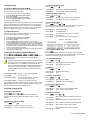
Introduction
The Digiplex EVO is a security and access control system with 8 on-board
zone inputs (16 with zone doubling) that is expandable to 48 or 192 zones
via the 4-wire combus. The EVO control panel features up to 999 users, 8
partitions, 32 doors and can support up to 254 modules in any combination.
The Digiplex EVO system provides the highest level of protection for banks,
high-security military and government sites, luxurious residential homes
and any place where maximum security is essential. These systems are
designed to be easy to use, and the modular concept of these systems
provides installers with labour-saving features that make expanding,
installing and servicing these systems quick and convenient.
Expand the EVO system by adding plug-and-play expansion modules
anywhere and in any combination on the 4-wire combus. Modules are
connected to the combus at the most convenient location and then their
zone inputs are assigned to the desired zone and partition. Also, only a
module’s used inputs are assigned to zones in the system. Keyswitches,
remote controls and unused module inputs do not use up zones. Once
installed, all combus modules, including motion detectors, can be
programmed remotely via a keypad or the WinLoad upload/download
software.
EVO also supports 32 virtual zones in addition to its security zones and
access control doors. Virtual zones can be used to automate PGM
activations without occupying a security zone and without affecting the
system’s security functions. The EVO system is a logical solution to every
installer’s security, access control and home automation installation needs.
1.1 Features of EVO48
Digital combus:
• Provides constant power, supervision and two-way communication
between the control panel and all its modules
• Supports up to 127 modules
• Connect modules up to 914m (3000ft) from the panel
• Sabotage-proof technology without additional wiring
8 on-board zones (16 w/ zone doubling) expandable to 48 zones via
4-wire combus
Built-in access control features
In-field firmware upgradeable via 307USB and WinLoad
Compatible with NEware
Automatic Daylight Saving Time feature
2 on-board solid-state relays PGM outputs (+ 3 optional), negative or
positive triggering
PGM1 can be used as a 2-wire smoke input
96 user codes
4 partitions
1024 events buffered
Program remote controls using the master or installer codes
Up to 96 remote controls with one MG-RTX3
Built-in-real-time clock backup battery
1.7A switching power supply
1 supervised bell output, auxiliary output and telephone line
Push button software reset (reset to default values and restart)
Push button to activate or deactivate the Auxiliary output
Fits in a 28cm x 28cm x 7.6cm (11in x 11in x 3in) metal box
The EVO series share the same programming for easy panel substitution
1.2 Features of EVO192
Same features as the EVO48 plus:
Expandable to 192 zones
5 on-board solid-state PGM outputs, negative or positive triggering
Supports up to 254 expansion bus modules
999 user codes
8 partitions
2048 events buffered
Up to 999 remote controls with one MG-RTX3
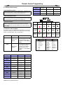
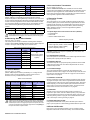
1.3 Hardware Difference
The programing for the EVO48 and EVO192 panels is identical. However,
certain differences may affect how many elements can be programmed.
Feature
EVO48
EVO192
Zones
48
192
Partitions
4
8
Users
96
999
On-board PGMs*
2
5
Modules
127
254
1.4 Specifications
Control Panel (Non-UL systems)
AC Power:
Battery:
Auxiliary Power:
16Vac, 20/40VA, 50-60Hz
12Vdc, 7Ah minimum
12Vdc 600mA typical, 700mA maximum,
fuseless shutdown at 1.1A
Bell Output:
1A, fuseless shutdown @ 3A
PGM Output:
PGM1 to PGM4 100mA solid-state relays with
+/- trigger, PGM5 Form C relay output rated at
5A/28Vdc N.O. / N.C.
Operational Temperature: -20°C to +50°C (4°F to +122°F)
All control panel outputs are rated to operate between 10.8Vdc and
12.1Vdc
Control Panel (UL compliant systems)
AC Power:
Battery:
Auxiliary Power:
16Vac, 40VA, 60Hz
12Vdc, 7Ah minimum
11.4 to 12.5Vdc, 200mA maximum, fuseless
shutdown at 1.1A
Bell Output:
11.4 to 12.5Vdc, 1A maximum, fuseless
shutdown @ 3A
PGM Output:
PGM1 to PGM4 100mA solid-state relays with
+/- trigger, PGM5 Form C relay output rated at
5A/28Vdc N.O. / N.C.
All control panel outputs are rated to operate between 11.4Vdc and
12.5Vdc
Specifications may change without prior notice.
General Note 1
Please note that only LCD and Grafica keypads can be used to program the
EVO system. LED keypads cannot be used to program the system.
General Note 2
Please note that the steps may differ when programming with the Grafica
keypad (DNE-K07). If not indicated, refer to the complete “Grafica User
Manual”, which can be downloaded for free from our website at
paradox.com
EVO Control Panel 1
2
Installation
2.1 Recommended Installation Procedure
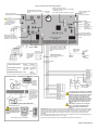
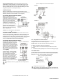
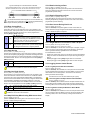
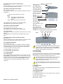
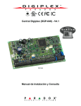
2.8 Programmable Outputs
1.
PGM1 to PGM4 are 100mA (max.) solidstate relays with +/- trigger. PGM5 is a 5A/
28Vdc N.O./ N.C. relay output. They can be
set at either normally open or normally
closed. If the current draw on PGM1 to
PGM4 is to exceed the current output, we
recommend using a relay as shown in
Figure 1.
2.
3.
4.
5.
Connect a small group of modules, including a keypad. See Figure 3
on page 3 for connection information.
Connect the battery and AC power. Enter section [4000] (see section
13.20 on page 31). Only the Clock Loss trouble and/or Bell Absent
trouble should appear. Verify the connection if a module does not
appear in section [4000], or if a module trouble occurs.
Disconnect AC power and the battery, follow steps 2, 3 and 4 for other
modules.
If modules were removed, enter [4005](see section 13.18 on page
31).
Connect an LCD keypad at various points from the control panel and
use the keypad’s built-in voltmeter.
2.2 Location & Mounting
Select a site that is not accessible to intruders and leave at least 2" around
the box to allow proper ventilation and heat dissipation. The site should be
dry and close to an AC, ground and telephone line connection.
2.3 Earth Ground
Connect the ground connector to the enclosure and cold water pipe or
grounding rod as per local electrical codes.
2.4 AC Power
Use a 16.5Vac (50/60Hz) transformer with a minimum 20VA rating. For
increased power use a 40VA rating. For UL Listed systems, use model
#BE156240CAA. For CSA listed systems, use model #BE116240AAA. Do
not use any switch-controlled outlets to power the transformer.
Do not connect the transformer or the backup battery until all wiring is completed.
When powering up the EVO control panel, the panel will begin a module scan.
2.5 Backup Battery
Connect a 12Vdc 7Ah rechargeable acid/lead or gel cell backup battery
(YUASA model #NP7-12 recommended). Verify the polarity, as reversed
connections will blow the battery fuse. For details on how to set the Battery
Charge Current to either 350mA or 850mA, see section 13.6 on page 30.
2.5.1 Battery Test
The control panel conducts a dynamic battery test under load every 60
seconds. If the battery is disconnected, if its capacity is too low or if the
battery voltage drops to 10.5 volts or less when there is no AC, the “Battery
Trouble” message will appear in the Trouble Display. At 8.5 volts, the panel
shuts down and all outputs close.
2.6 Auxiliary Power Terminals
The auxiliary power supply can power accessories in the security system. A
fuseless circuit protects the auxiliary output against overload and shuts it
down if the current exceeds 1.1A. Auxiliary power will resume once the
overload condition has restored. Press and hold the AUX button for two
seconds to turn AUX power on and off.
2.7 Bell/Siren Output
The bell output supplies 12Vdc upon alarm and can support one 30-watt or
two 20-watt sirens. The bell output will automatically shut down if the
current exceeds 3A. If the load on the BELL terminals returns to normal
(≤3A), the control panel will re-instate power to the BELL terminals. Please
verify correct polarity.
For connection of self-contained bell/siren, see Figure 3 on page 3.
When the bell output is not used, the “Bell Absent” message appears in the
Trouble Display. To avoid this, connect a 1kΩ resistor across the bell output. UL
Note: The keypads must be programmed to beep with all troubles.
2 Reference & Installation Manual
Figure 1: PGM & Relay
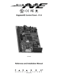
2.9 Keyswitch Connections
Connect the keyswitches to the keypad,
control panel, or Zone Expansion Module's
hardwired input terminals as shown in
Figure 2.
2.10 Access Control Connections
For all access control explanations and
connection drawings, refer to Access Control:
System Features on page 36.
Figure 2: Keyswitch
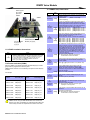
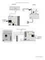
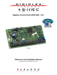
Figure 3: EVO Control Panel Wiring Diagram
AUX LED and AUX control button.
(Activates and deactivates the auxiliary
output)
Charging and battery test
LED (every 60 seconds).
Built-in RTC
See page 7.
VDMP3 voice module module
connects directly to the control panel via the EBUS
and DIALER connectors
(See ‘VDMP3 Installation Instructions” on page 27.)
Used for In-Field Firmware
Upgrade through a
307USB
Direct Connect Interface.
Red "STATUS" LED:
Flashing - Indicates proper
operation.
Always On - Panel is using
a phone line.
Fast Flash - Indicates a control
panel failure.
Off Control panel error.
12Vdc 7Ah Rechargeable
Acid/Lead or Gel Cell
Backup Battery
Press and hold the Reset
button for 2 seconds to restart
the panel without removing
power.
PGM Trigger: This Jumper
allows you to choose whether
the solid-state relay PGMs are
grounded (-) or give out 12V (+).
Optional on EVO48
Four pin connector
can be used for
quick installation
of a keypad or
module.
For the hardwired connections, see
Single Zone Input Connections on page
6 and Double Zone Connections on
page 6.
AUX Power (Auxiliary):
Provides up to 700mA. Refer to
Table 1 on page 4
AWG#14 single
conductor solid
copper wire
Ground
clamp
Cold water
pipe
grounding
To metallic
enclosure
Combus
Bell/Siren
Door Contact
* if EOL is enabled in
the control panel
Bell/Siren
Connection for Self-Contained Bell/Siren
The sum of the current
drawn from the BELL and
AUX must be limited to
2.0A. Exceeding this limit will
overload the panel power supply
and lead to complete system
shutdown.
40VA transformer strongly recommended
The combus supports a maximum of 127 (EVO48)
or 254 (EVO192) modules. Although external power
supplies can be used to provide power to modules
connected far from the control panel, the total
distance of all runs of wire combined cannot
exceed 914m (3000ft). For example, if ten runs of
wire measuring 305m (1000ft) each are connected
to the control panel, the total distance would be
3048m (10, 000ft), which exceeds the system's
capacity.
Before adding any module to the control panel
make sure you shutdown the AUX output by
pressing and holding the AUX button for 3
seconds.
PLEASE NOTE: When powering up the EVO control panel, the panel will begin a module scan to verify if all the modules
connected to the panel are operational. The scanning process will take between 30 seconds and 3 minutes to complete
depending on the number of modules connected to the control panel. The module scan is complete when the LCD
keypad begins to show the partition status. Only after the module scan is complete will the control panel be fully
operational.
When installing the combus wires in a noisy environment, or when connecting the combus across separate buildings, you
must use a shielded cable. Refer to section 2.15.1 on page 6.
Please see UL and ULC Warnings on page 54 for applicable UL/ULC warnings and information.
EVO Control Panel 3
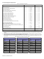
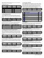
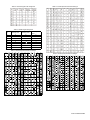
2.11 Calculating Power Requirements
Table 1: Power Requirement Calculation
Description
QTY.
mA used by each
Total mA
Grafica Graphic LCD Keypads (DNE-K07):
_______
X
130mA =
__________ mA
LCD Keypads (EVO641):
_______
X
110mA =
__________ mA
LCD Keypads with Built-in Reader (EVO641R):
_______
X
120mA =
__________ mA
LED Keypads (DGP2-648):
_______
X
110mA =
__________ mA
Motion Detector Modules (DG85, DGP2-50/60/70):
_______
X
30mA
=
__________ mA
Door Contact Modules (DGP2-ZC1):
_______
X
15mA
=
__________ mA
1-Zone Expansion Modules (DGP2-ZX1):
_______
X
30mA
=
__________ mA
4-Zone Expansion Modules (APR3-ZX4):
_______
X
30mA
=
__________ mA
8-Zone Expansion Modules (APR-ZX8):
_______
X
30mA
=
__________ mA
Magellan Wireless Expansion Modules (MG-RTX3):
_______
X
35mA
=
__________ mA
4-PGM Expansion Modules (APR3-PGM4):
_______
X
150mA =
__________ mA
Printer Modules (APR-PRT3):
_______
X
25mA
=
__________ mA
DVACS Modules (DGP2-DVAC):
_______
X
40mA
=
__________ mA
Annunciator Modules (DGP2-ANC1):
_______
X
20mA
=
__________ mA
InTouch Voice-Assisted Arm/Disarm Modules (APR3-ADM2):
_______
X
105mA =
__________ mA
Hub and Bus Isolator (APR3-HUB2):
_______
X
50mA
=
__________ mA
Access Control Module (DGP-ACM12):
Note: The DGP-ACM12 consumes 130mA from its own power supply.
The DGP-ACM11 consumes 120mA when connected on the combus for power.
_______
X
120mA =
__________ mA
Listen-In Module (DGP-LSN4)
_______
X
60mA
=
__________ mA
Internet Module (IP100)
_______
X
110mA =
__________ mA
Plug-In Voice Module (VDMP3)
_______
X
35mA
__________ mA
=
Other devices such as hardwired motion detectors
__________ mA
Maximum available milliamps = 700mA
1.
2.
3.
GRAND TOTAL
__________ mA
Using Table 1, calculate the total number of milliamps (mA) required by each device, module, and accessory in the system. Please take into account
devices connected to the control panel’s PGM outputs. Since the BELL output has its own power supply, do not include the sirens connected to it in the
calculation.
If Grand Total is less than 700mA, go to step 3. If the value is greater, an external power supply is required (see Figure 5 on page 5) to provide the
additional power needed. Proceed with step 3 and refer to the example in Figure 4 on page 5.
Due to the degradation of a power signal over long distances, EACH length or run of wire in the system can support only a specific number of milliamps
(mA). Using Table 2, determine how many milliamps each length of wire can support. Please note that the total number of milliamps (mA) can never
surpass 700mA.
Table 2: Milliamps (mA) Limitations For Each Run of Wire
Gauge: 18AWG, Surface: 0.823mm2
Gauge: 22AWG, Surface: 0.326mm2
Gauge: 24AWG, Surface: 0.205mm2
Length of each run
of wire
Available
milliamps (mA)
Length of each run
of wire
Available
milliamps (mA)
Length of each run
of wire
Available
milliamps (mA)
30m(100ft.)
61m(200ft.)
91m(300ft.)
122m(400ft.)
152m(500ft.)
183m(600ft.)
213m(700ft.)
244m(800ft.)
274m(900ft.)
305m(1000ft.)
457m(1500ft.)
610m(2000ft.)
762m(2500ft.)
914m(3000ft.)
700
700
700
700
690
575
493
431
383
345
230
172
138
115
30m(100ft.)
61m(200ft.)
91m(300ft.)
122m(400ft.)
152m(500ft.)
183m(600ft.)
213m(700ft.)
244m(800ft.)
274m(900ft.)
305m(1000ft.)
700
682
454
341
273
227
195
170
151
136
30m(100ft.)
61m(200ft.)
91m(300ft.)
122m(400ft.)
152m(500ft.)
183m(600ft.)
700
429
286
214
171
143
4 Reference & Installation Manual
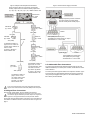
Figure 4: Sample Power Requirement Calculations
Figure 5: External Power Supply Connections
Power required by devices connected to control panel’s
auxiliary output must not exceed the auxiliary output’s limit:
(A) + (B) + (C) + (D) + (E) + (F) + (G) = 368mA<700mA = OK
Control Panel
aux. output
= 700mA
15m (50ft)
61m (200ft)
APR-PRT3
(A) = 25mA
Milliamps required by devices connected
to a power supply do not draw power
from the control panel’s auxiliary output.
EVO641
(D) = 110mA
7.5m (25ft)
Module
15m (50ft)
DGP2-70
(E) = 30mA
APR-ZX8
(B) = 30mA
22 AWG
30m (100ft)
152m (500ft) from control panel
152 (500ft) from control panel’s aux. output
Therefore this run = max. 273mA
7.5m (25ft)
As indicated in Table 2 on
page 4, this run of wire can
support 700mA. Total mA on
this run of wire:
(A) 25mA + (B) 30mA =
55mA<700mA = OK
EVO641
(F) = 110mA
15m (50ft)
Power Supply
EVO641
(G) = 110mA
290m (950ft)
DGP2-60
(C) = 30mA
305m (1000ft)
Module
610m (2000ft) from control panel
152m (500ft) from power supply
Therefore this run = max. 273mA
91m (300ft)
As indicated in Table 2 on
page 4, this run of wire
can support 454mA. Total
mA on this run of wire:
(D) 110mA + (E) 30mA +
(F) 110mA + (G) 110mA
= 360mA<454mA = OK
As indicated in Table 2 on
page 4, this run of wire
can support 136mA. Total
mA on this run of wire:
(A) 25mA + (C) 30mA =
55mA<136mA = OK
2.13 Addressable Zone Connections
The control panel includes eight hardwired input terminals for use with
traditional hardwired (non-combus) door contacts, smoke detectors and/or
motion detectors.
The control panel also supports hardwire zone expansion modules. Figure
6 shows single zone (ATZ disabled) hardwire input terminal connections
recognized by the Digiplex EVO system. For UL listed installations, use
EOL resistor part #2011002000.
Do not use the same transformer for the control panel and the external power
supplies. Do not install modules more than 914m (3000ft) from the control panel.
2.12 Keypad Zone Connections
Every keypad, except Grafica, has one hardwire input terminal.
Even with the ATZ feature enabled in the control panel, only one device can be
connected to the keypad’s hardwired input terminal. Tamper is not recognized on
keypad zones. The keypad zone follows the control panel’s EOL definition.
The keypad communicates the status of the zone to the control panel via
the combus. The detection device is connected as shown in Figure 3 on
page 3.
EVO Control Panel 5
Figure 6: Single Zone Input Connections
N.C. Contacts, No EOL
N.C., With EOL
Ul/ULC Configuration
CONTROL PANEL TERMINAL
CONTROL PANEL TERMINAL
2.14 Double Zone Connections
Enabling the ATZ feature (see section 4.3) allows you to install two
detection devices per input terminal. Connect the devices as shown in
Figure 7. For UL listed Burglary System installations only, use EOL resistor
part #2011002000.
Figure 7: Double Zone Connections
N.C., No EOL Resistor
CONTROL PANEL TERMINALS
N.O., With EOL
Ul/ULC Configuration
N.C. Contacts, No EOL,
With tamper recognition
N.C., No EOL, With Tamper Recognition
CONTROL PANEL TERMINAL
CONTROL PANEL TERMINAL
CONTROL PANEL TERMINALS
N.C., With EOL and Tamper & Wire Fault
Recognition (UL/ULC)
CONTROL PANEL TERMINALS
N.C. With EOL, With Tamper
& Wire Fault Recognition
UL/ULC Configuration
N.O., With EOL, With Tamper
& Wire Fault Recognition†
CONTROL PANEL TERMINAL
CONTROL PANEL TERMINAL
2.15 Combus Connections
The 4-wire combus can support 127 (EVO48) or 254 (EVO192) modules.
Use star and/or daisy chain configuration. The total length of wire cannot
exceed 914m (3000ft).
Before connecting a module to the combus, remove AC and battery power from the
control panel.
2.15.1 Connecting the Combus in Noisy Environments
When installing the combus wires in proximity to high electrical
interferences or across separate buildings, use shielded cables:
† Enable ATZ (see section 4.3 on page
10) and connect as follows (extra input
cannot be used)
6 Reference & Installation Manual
Within the Same Building: Strip the outer jacket at one end of the
shielded cable to expose the shield and connect the shield to the control
panel ground (not the dialer ground), while leaving the shield at the other
end of the cable open (floating).
Across Separate Buildings: Strip the outer jacket at one end of the
shielded cable to expose the shield. In the same building as the control
panel, connect the exposed shield to any earth ground available, while
leaving the shield at the other end of the cable open (floating). The same
configuration applies for any subsequent building.
Figure 10: Telephone Line Connection Examples
Example 1:
EVO
Dialer
2.16 Fire Circuits
Assign the smoke detectors connected to the control panel or zone
expansion input terminals to a zone and define the zone's parameters as a
Fire Zone (see section 4.4.12 and section 4.4.13 on page 11).
Ground
clamp
2.16.1 Smoke Detector Installation (2-Wire)*
PGM1 can be defined as a 2-wire
smoke detector input (see section 12.6
on page 29). Connect the 2-wire smoke
detectors as shown in Figure 8. If a line
short occurs or the smoke detector
activates, whether the system is armed
or disarmed, the control panel will
generate an alarm. If the line is open,
the “Zone Fault” trouble indication
appears in the Trouble Display and the
report code is sent to the monitoring
station, if programmed.
Main line
Figure 8:
2-Wire Detectors
PGM1 becomes
input# 255
Example 2:
N.O. contacts
1K9
EOL
EVO
Dialer
Smoke detectors
Note: It is recommended that the smoke
detectors be connected in a daisy chain
configuration.
* UL Note: Not to be used with UL Listed systems.
Ground
clamp
2.16.2 ESL CleanMe® Installation
Connect ESL smoke detectors like the standard smoke detectors. Avoid
connecting more than 20 ESL smoke detectors. When an CleanMe signal
is sent, the control panel will generate a Zone Fault trouble and may
transmit the Fire Loop report code to the monitoring station. The trouble will
be cleared if there is no CleanMe signal for 255 seconds. If an alarm
occurs, the trouble will be cleared until it is detected again.
2.16.3 Smoke Detector Installation (4-Wire)
Recommended: System Sensor model
2112/24D smoke detectors. Connect the
4-wire smoke detectors and a relay as
shown in Figure 9. To comply with UL955,
install the 4-wire smoke detectors with 18
gauge wire. If power is interrupted, the
relay causes the control panel to transmit
the Fire Loop Trouble report programmed
in section [2906].
To reset (unlatch), connect the smoke
detector’s negative (-) to a PGM. Then
program the PGM with the “Smoke
Detector Power Reset” activation event
(see section 12.1 on page 29; Event
Group #067, start # 004, end # 004) to
interrupt power to the smoke detector for
four seconds when the [CLEAR] and
[ENTER] keys are pressed and held for two
seconds.
Figure 9: 4-Wire Detectors
Main line
2.17 Telephone Line Connections
The telephone lines can be connected directly to the control panel or
through a CA38A or RJ31 as shown in Figure 10.
UL Note: Installer must verify line seizure after every installation
For TBR-21 compliance, please note the following:
1. The EVO can be connected to the telephone network via an RJ-11
connector.
2. The Maximum Dialing Attempts cannot exceed 15 attempts (page 25).
2.18 Built-in RTC
The RTC will save the EVO’s internal clock when both the AC and battery
power have been lost. The RTC uses a 3V lithium battery (CR2032) with a
battery life of 11 years. Change the battery as shown below:
Figure 11: Changing the RTC’s Battery
3V Lithium Battery
(CR2032)
Note: It is recommended that the
smoke detectors be connected in a
daisy chain configuration.
If ATZ is enabled (see section 4.3 on page 10), do not use the extra input (doubled
zone).
Insert the battery with
the positive facing up
and the negative facing
down.
Reprogram the control panel’s clock after changing the battery.
Danger of explosion exists if the lithium battery is incorrectly replaced. Replace only
with the same or equivalent type recommended by the manufacturer. Dispose of used
batteries according to the manufacturer’s instructions.
* For installations without EOL, remove 1KΩ
EVO Control Panel 7
3
Programming Methods
3.1 WinLoad Uploading/Downloading Software*
3.4 Programming Through a Keypad
We recommend programming the control panel with WinLoad. Refer to
WinLoad Software on page 38 for details.
Use the “EVO Programming Guide” to record how the sections were
programmed. To enter programming mode:
* UL Note: Not verified by UL
1.
2.
3.
4.
3.2 Paradox Memory Key
The Paradox Memory Key can copy the programmed contents of one
control panel into as many others. Not to be used with UL Listed
systems.
Copy to Memory Key
1. Insert the Memory Key (PMC-4) onto the control
panel’s connector labelled “MEM KEY”.
2. To copy the contents to the Memory Key except
zone numbering and sections [0501] to [0532],
enter installer programming mode, then enter
section [4020]. (Depending on the memory key, the
labels may or may not be included.)
To copy the contents to the Memory Key including
zone numbering and sections [0501] to [0532],
enter section [4021]. (Depending on the memory
key, the labels may or may not be included.)
3. When the keypad emits a confirmation beep, remove the Memory Key.
Remove the write protect jumper.
Download to Control Panel
1) Insert the Memory Key onto the control panel’s
connector labelled “MEM KEY”.
2) To download the contents of the Memory Key except
zone numbering and sections [0501] to [0532], enter
installer programming mode and then enter section
[4010]. (Depending on the memory key, the labels
may or may not be included.)
To download the contents of the Memory Key
including zone numbering and sections [0501] to [0532], enter installer
programming mode and then enter section [4011].(Depending on the
memory key, the labels may or may not be included.)
3) When the keypad emits a confirmation beep, remove the Memory Key.
Figure 12: Using the Memory Key
Jumper ON =
Can copy and download
contents of the Memory Key
Jumper OFF =
Cannot override contents
of the Memory Key
Press and hold the [0] key.
Key in the [INSTALLER CODE] (default = 000000).
Key in the 4-digit [SECTION].
Key in required [DATA]. Refer to the “EVO Programming Guide” or to
the corresponding sections in this manual.
For LCD Keypads: The control panel will save the data and go to the next
section or press the [ENTER] key to save the data and go to the next
section. Press the [CLEAR] key go to the preceding step or to erase the
current data entry.
For Grafica Keypads: Press Grafica’s center action key (Save) to save the
data and go to the next section. Press the right action key (Exit) to go to the
preceding step or press the left action key (Clear) to erase the current data.
3.4.1 Feature Select Programming
Most of the options are programmed using the Feature Select Method.
For LCD Keypads: The option is considered ON when the number
appears within the brackets on the LCD keypad. Turn options ON and OFF
by pressing the corresponding keys on the keypad and then press [ENTER]
to save.
For Grafica Keypads: Select or clear the check boxes or set the options by
pressing the corresponding keys on the keypad. The feature is considered
ON when its check box is selected. Press the Grafica’s center action key
(Save) to save.
3.4.2 Decimal Programming
Sections may require 3-digit decimal values from 000 to 255.
3.4.3 Hexadecimal Programming
Sections may require Hexadecimal values from 0 to F. Press:
For LCD Keypads:
[0] to [9]
= values 0 to 9 respectively
[STAY] key
=A
[DISARM] key = D
[FORCE] key
=B
[BYP] key
=E
[ARM] key
=C
[MEM] key
=F
For Grafica Keypads:
[0] to [9]
= values 0 to 9 respectively
[#]
= A to F (press the key until the desired letter appears)
3.5 Module Programming Mode
To program a Module with a keypad, enter Module Programming Mode:
1.
2.
3.
4.
5.
3.3 Module Broadcast
Keypads and other modules can also be programmed easily by using
Module Broadcast (see section 13.16 on page 31). Once a module is
programmed, its sections can be sent to other similar modules through the
combus.
8 Reference & Installation Manual
Press and hold the [0] key.
Key in the [INSTALLER CODE] (default = 000000).
Key in section [4003].
Key in 8-digit [SERIAL NUMBER] of the module.
Key in 3-digit [SECTION] and required [DATA]. Refer to the “Module
Programming Guide” for details.
The control panel will redirect all programming to the selected module. To
exit the Module Programming Mode, press the [CLEAR] key on LCD
keypads, or the right action key (Exit) on Grafica keypads.
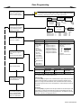
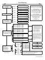
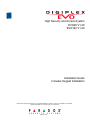
4
Zone Programming
In any Zone Programming option, pressing [ACC] will save the data and go
to the next zone on the same option screen. Pressing [TRBL] will save the
data and go to the previous zone on the same option screen.
Enter Section [0400], then
enter the number of the
zone you want to program
Hardwired
Device A
Keypad
SN#: 1A000252
Keypad Zone
Control Panel
SN#:020000A2
Enter the zone’s 8-digit
serial and 3-digit input
number (The input number
is not needed for module
with only one input)
2
COMMUNICATION
CombusNETWORK
7
Hardwired
Device B
Detector A:
Hardwired Device A:
Hardwired Device B:
Hardwired Device C:
Enter the zone’s parameters
(01) (*2*****) default
APR3-ZX8 Module
SN#: 34000041
1
2
Input Terminals
3 4 5 6
Zone#
1=
2=
3=
4=
7
Section#
[0001]
[0002]
[0003]
[0004]
Input 5
Hardwired
Device C
Serial#
21000033
1A000252
020000A2
34000041
Input#
N/A
N/A
002
005
8
Zone Definition
Partition
Zone Option
_____
_____
12345678
0 - Disabled (default)
1 - Entry Delay 1
2 - Entry Delay 2
3 - Follow
4 - Instant
5 - 24Hr Buzzer
6 - 24Hr Burglary
1 - Assigned to Partition 1
(default)
2 - Assigned to Partition 2
3 - Assigned to Partition 3
4 - Assigned to Partition 4
[1] Auto Zone Shutdown Enabled
[2] Bypass Enabled (default)
[3] Stay Zone
[4] Force Zone
[5]
[6]
Zone Alarm Type
off
off
Steady Alarm
off
on
Pulsed Alarm
on
off
Silent Alarm
on
on
Report Only
[7] Intellizone
[8] Delay before Transmission
7 - 24Hr Hold-up
Enter the zone’s report
codes
(00) (00) (00) (00) default
8
Input 2
1
Input Terminals
3 4 5 6
Detector A
SN#: 21000033
8 - 24Hr Gas
9 - 24Hr Heat
A - 24Hr Water
B - 24Hr Freeze
C - Delayed 24Hr
Fire
D - Standard 24Hr
Fire
E - Stay Delay 1
F - Stay Delay 2
5 - Assigned to Partition 5
6 - Assigned to Partition 6
7 - Assigned to Partition 7
8 - Assigned to Partition 8
Enter the zone’s label
.
Alarm Report Code
Alarm Restore
Report Code
Tamper Report
Code
Tamper Restore
Report Code
__ / __
__ / __
__ / __
__ / __
Ademco slow, Silent Knight fast, SESCOA, Ademco express or Pager formats:
Key-in desired 2-digit hex values from 00 to FF.
Press [ENTER] to save and
go to the next zone
Pressing [CLEAR] twice will
exit the zone programming
menus. Press [ENTER]
before pressing clear to
save your modifications.
Ademco format:
Use section [4032] to program a set of default Ademco report codes from the Auto
Report Code Programming on page 26. Then to program the remaining report
codes or to change some of the defaults, enter the individual sections and key-in
the desired 2-digit hex value found in the Appendix 2: Contact ID Report Code List
on page 42.
SIA format:
Use section [4032] to program a set of SIA report codes from the Auto Report Code
Programming on page 26. Codes that have not been set to default can be set to
default manually by entering FF in the appropriate section. To disable the reporting
of an event, enter 00 in the appropriate section
EVO Control Panel 9
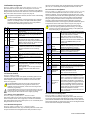
4.1 Zone Programming
4.4 Zone Definitions
Two different methods can be used to program zones:
4.4.1 Zone Disabled
4.1.1 Using section [0400]
In any Zone Programming option, pressing [ACC] will save the data
and go to the next zone on the same option screen. Pressing
[TRBL] will save the data and go to the previous zone on the same
option screen.
4.1.2 Using zone serial and input numbers
If you are not using an EVO641 or an EVO641R keypad, you can only
program zones 1 to 96 through sections [0001] to [0096].
Zone
Zone
Number Numbering
Zone
definitions
Zone Partition
Zone Options
Assignment
1
[0001]
[0101]
[0201]
[0301]
2
[0002]
[0102]
[0202]
[0302]
+1 per zone
+1 per zone
+1 per zone
+1 per zone
[0096]
[0196]
[0296]
[0396]
96
4.2 Zone Numbering
SECTION [0400]
SECTIONS [0001]
TO
[0400]: FIRST DIGIT = 0
SECTIONS [0101] TO [0196]: FIRST DIGIT = 0
Disables the corresponding zone. Zones are disabled by default.
SECTION
Allows you to program zones 001 through 192 as shown in the diagram on
page 9.
[0096]
• To assign an addressable PIR or door contact to the combus, program
the module’s serial number into the section corresponding to the zone.
• To assign a detection device connected to a module or control panel's
hardwired input terminal, program the module's or control panel's serial
number and the input number to the desired zone. See the “Digiplex
Modules Programming Guide” for details of its input numbers (input
numbers not required for keypad zones).
If PGM1 is defined as a smoke detector input (see section 12.6 on page 29), the
control panel will recognize it as input # 255.
4.2.1 Clearing a Zone’s Numbering
4.4.2 Entry Delays 1 and 2
[0400]: FIRST DIGIT = 1 AND 2
SECTIONS [0101] TO [0196]: FIRST DIGIT = 1 AND 2
(default Entry Delay 1= 030, Entry Delay 2 = 060) A zone defined as Entry
Delay 1 follows the Entry Delay 1 Timer of its assigned partition. A zone
defined as Entry Delay 2 follows the Entry Delay 2 Timer of its assigned
partition. Each partition includes two Entry Delay Timers. To program an
Entry Delay Timer, key in the desired 3-digit delay value (001 to 255
seconds) into the corresponding section.
SECTION
Partition 1
Entry Delay 1 Timer: [3111]
Entry Delay 2 Timer: [3112]
Partition 2
Entry Delay 1 Timer: [3211]
Entry Delay 2 Timer: [3212]
Partition 3
Entry Delay 1 Timer: [3311]
Entry Delay 2 Timer: [3312]
Partition 4
Entry Delay 1 Timer: [3411]
Entry Delay 2 Timer: [3412]
Partition 5
Entry Delay 1 Timer: [3511]
Entry Delay 2 Timer: [3512]
Partition 6
Entry Delay 1 Timer: [3611]
Entry Delay 2 Timer: [3612]
Partition 7
Entry Delay 1 Timer: [3711]
Entry Delay 2 Timer: [3712]
Partition 8
Entry Delay 1 Timer: [3811]
Entry Delay 2 Timer: [3812]
These are the same timers used for Stay Delay zones.
4.4.3 Follow Zones
[0400]: FIRST DIGIT = 3
SECTIONS [0101] TO [0196]: FIRST DIGIT = 3
The control panel waits until the end of the Entry Delay before generating
an alarm if an Entry Delay zone opens before the Follow zone.
SECTION
4.4.4 Instant Zones
Using section [0400]
1. Enter the zone number you wish to delete.
2. Press [0] all the way through the serial/input, parameters and report
codes screen.
3. Press [ENTER] to exit.
SECTION
Using an LCD Keypad:
1. Enter a section number between [0001] to [0096].
2. Press [0] and then [ENTER] to save and exit.
4.4.5 24Hr Buzzer Zones
Using a Grafica Keypad:
1. Enter a section number between [0001] to [0096].
2. Press [0] to clear the serial number.
3. Highlight the input number and then press [0] to clear the data.
4. Press Grafica’s center action key (Save) to save and exit.
[0400]: FIRST DIGIT = 4
SECTIONS [0101] TO [0196]: FIRST DIGIT = 4
When an armed Instant zone opens, the control panel immediately
generates an alarm.
[0400]: FIRST DIGIT = 5
SECTIONS [0101] TO [0196]: FIRST DIGIT = 5
Whenever a 24Hr Buzzer zone opens, the control panel activates the
keypad buzzer to indicate that the zone was breached. The control panel
will report the alarm, but will not enable the bell/siren output. Enter any valid
access code on the keypad to stop the buzzer.
SECTION
The keypads must be assigned to the same partition as the 24Hr Buzzer zone or the
buzzer will not activate. UL Note: Not to be used for perimeter protection.
4.3 Zone Doubling (ATZ)
SECTION [3033]: OPTION [8]
(default = disabled) Fire Zones cannot be doubled.
4.4.6 24Hr Burglary Zones
Input
Doubled Zone Input
Input 01
Input 09 (ATZ of Input 01)
[0400]: FIRST DIGIT = 6
SECTIONS [0101] TO [0196]: FIRST DIGIT = 6
When a 24Hr Burglary zone opens, the control panel will immediately
generate a burglary alarm.
Input 02
Input 10 (ATZ of Input 02)
4.4.7 24Hr Hold-up Zones
Input 03
Input 11 (ATZ of Input 03)
SECTION
Input 04
Input 12 (ATZ of Input 04)
Input 05
Input 13 (ATZ of Input 05)
Input 06
Input 14 (ATZ of Input 06)
Input 07
Input 15 (ATZ of Input 07)
Input 08
Input 16 (ATZ of Input 08)
SECTION
10 Reference & Installation Manual
[0400]: FIRST DIGIT = 7
SECTIONS [0101] TO [0196]: FIRST DIGIT = 7
When a 24Hr Hold-up zone opens, the control panel will immediately
generate an alarm.
The SIA FSK reporting format includes specific codes to identify the
alarm as a Hold-up, Gas, Heat, Water, or Freeze Alarm.
4.4.8 24Hr Gas Zones*
4.4.14 Stay Delay Zone
[0400]: FIRST DIGIT = 8
SECTIONS [0101] TO [0196]: FIRST DIGIT = 8
When a 24Hr Gas zone opens, the control panel will immediately generate
an alarm.
SECTION
SECTION
4.4.9 24Hr Heat Zones**
[0400]: FIRST DIGIT = 9
SECTIONS [0101] TO [0196]: FIRST DIGIT = 9
When a 24Hr Heat zone opens, the control panel will immediately generate
an alarm.
SECTION
** UL Note: UL Listed compatible devices must be used for UL systems. For
UL Listed systems, this type of zone should be programmed as a pulsing Fire
alarm.
[0400]: FIRST DIGIT = E AND F
SECTIONS [0101] TO [0196]: FIRST DIGIT = E AND F
Using the Regular or Force arming methods, the control panel processes
the zone as an Instant zone (see section 4.4.4 on page 10). Using the Stay
or Instant arming methods and the zone is triggered, the control panel will
not generate an alarm until the programmed Stay Delay elapses. A zone
defined as Stay Delay 1 follows the Entry Delay 1 Timer of its assigned
partition. A zone defined as Stay Delay 2 follows the Entry Delay 2. To
program the Entry Delay Timers, refer to Entry Delays 1 and 2 on page 10.
4.5 Zone Partition Assignment
SECTION [0400]: SECOND DIGIT = 1 TO 8
SECTIONS [0101] TO [0196]: SECOND DIGIT = 1
Assign zones to one partition.
TO
8
4.4.10 24Hr Water Zones*
[0400]: FIRST DIGIT = A
SECTIONS [0101] TO [0196]: FIRST DIGIT = A
When a 24Hr Water zone opens, the control panel will immediately
generate an alarm.
SECTION
4.4.11 24Hr Freeze Zones*
[0400]: FIRST DIGIT = B
SECTIONS [0101] TO [0196]: FIRST DIGIT = B
When a 24Hr Freeze zone opens, the control panel will immediately
generate an alarm.
SECTION
* UL Note: UL Listed compatible devices must be used for UL systems. For UL
Listed systems, this type of zone must be programmed as a silent auxiliary
alarm.
4.4.12 Delayed 24Hr Fire Zone (Not to be used with UL Listed systems)
[0400]: FIRST DIGIT = C
SECTIONS [0101] TO [0196]: FIRST DIGIT = C
The Delayed 24Hr Fire Zone definition from Figure 14 on page 12 is used in
homes where a smoke detector often generates false alarms. A zone
programmed as Fire becomes normally open and requires an EOL resistor.
SECTION
The keypads must be assigned to the same partition as the Delayed 24Hr Fire zone
for the buzzer to activate.
* UL Warning: For UL/ULC installations, a Fire zone cannot be bypassed and its
alarm type must be Pulsed (audible).
4.4.13 Standard 24Hr Fire Zone
[0400]: FIRST DIGIT = D
SECTIONS [0101] TO [0196]: FIRST DIGIT = D
A zone programmed as Fire becomes normally open and requires an EOL
resistor. When a Standard 24Hr Fire Zone triggers, the control panel can:
• send a Zone Alarm report code (see section 9.2.1 on page 22).
• send a Fire Loop Trouble Report (see section 9.2.11 on page 23) if a
tamper/wiring fault occurs on a Fire Zone. A “Zone Fault Trouble” will
also appear in the keypad's Trouble Display.
• generate a Fire alarm, which can be silent, pulsed, steady or report only.
Fire alarms generate an intermittent signal (see Figure 13).
SECTION
* UL Warning: For UL/ULC installations, a Fire Zone cannot be bypassed
and its alarm type must be Pulsed (audible).
4.6 Zone Options
The zone options from are described below. Refer to the EVO programming
guide for additional information on Zone Programming.
4.6.1 Auto Zone Shutdown
[0400]: OPTION [1]
SECTIONS [0101] TO [0196]: OPTION [1]
(default = 000) When enabled, the control panel will stop generating alarms
once the Auto Zone Shutdown Limit is reached. It resets every time the
partition that is assigned to the corresponding zone is armed. To program
the Auto Zone Shutdown Limit, enter the desired 3-digit counter (000 to
015) into section corresponding to the desired partition (000 = disabled):
SECTION
Partition 1: [3114]
Partition 5: [3514]
Partition 2: [3214]
Partition 6: [3614]
Partition 3: [3314]
Partition 7: [3714]
Partition 4: [3414]
Partition 8: [3814]
4.6.2 Bypass Zones
[0400]: OPTION [2]
SECTIONS [0101] TO [0196]: OPTION [2]
(default = enabled) Allow zones to be Manually Bypassed.
SECTION
4.6.3 Stay Zones
[0400]: OPTION [3]
SECTIONS [0101] TO [0196]: OPTION [3]
Only zones with option [3] enabled will be bypassed when the partition is
Stay armed or Instant armed. All other zones will remain activated. Fire
Zones cannot be set as Stay Zones.
SECTION
4.6.4 Force Zones (Not to be used with UL Listed systems)
[0400]: OPTION [4]
SECTIONS [0101] TO [0196]: OPTION [4]
Only zones with option [4] enabled can be bypassed when the partition is
Force armed. Fire Zones cannot be Force Zones.
SECTION
Figure 13: Bell/Siren Output During Fire Alarm
EVO Control Panel 11
4.6.5 Alarm Types
Figure 14: Delayed 24Hr Fire Zone
[0400]: OPTION [2] & [6]
SECTIONS [0101] TO [0196]: OPTIONS [5] & [6]
SECTION
Option Feature
[5]
Delayed Fire Zone
Triggered
Description
[6]
OFF OFF
ON
OFF
OFF
ON
ON
ON
Activate bell/siren output & delay
report transmission for 30s.
sends the report code and activates the bell
output
sends the report code and pulses the bell output
Pulsed Alarm
(see Figure 14)
sends the report code, but the bell output is not
Silent Alarm
activated. Partition must be disarmed.
Steady Alarm
Report Only
Yes
Has the zone
closed within
30s?
sends the report code. Disarming is not required.
No
4.6.6 Intellizone*
[0400]: OPTION [7]
SECTIONS [0101] TO [0196]: OPTION [7]
(default = 032) If an alarm condition occurs on a zone with option [7]
enabled, the control panel triggers the Intellizone Delay. Fire Zones cannot
be set as Intellizones. An alarm will only be generated if the selected
conditions occur during the Intellizone Delay:
1. An alarm occurs on another zone defined as Intellizone.
2. The zone in alarm restores and reoccurs.
3. The zone stays in alarm for the entire Intellizone Delay.
SECTION
Has a 2nd
Delayed Fire
Zone opened
in 30s?
Yes
Latch alarm and transmit
report code as described
in section 4.4.13
No
Any key on
keypad
pressed
within 30s?
Key in the desired 3-digit delay value (010 to 255 seconds, default value is
32 seconds) into the section corresponding to the desired partition
Any value less than 10 seconds will be replaced by the default
value of 32 seconds.
No
Yes
Bell/siren silenced. Delay report
transmission an additional 90s.
Partition 1: [3110] Partition 3: [3310] Partition 5: [3510] Partition 7: [3710]
Partition 2: [3210] Partition 4: [3410] Partition 6: [3610] Partition 8: [3810]
No
* UL Note: For UL Listed systems, the detection pattern of both zones must
be installed so that each zone has the capability of protecting the area alone.
Problem
corrected?
Yes
4.6.7 Intellizone Options
Use these options to enable or disable different Intellizone related options.
END
Alarm Disabled
Partition 1: [3126] Partition 3: [3326] Partition 5: [3526] Partition 7: [3726]
Partition 2: [3226] Partition 4: [3426] Partition 6: [3626] Partition 8: [3826]
Option Description
[1]
[2]
[3]
[5]
Intellizone Delay (default = disabled)
The zone stays in alarm for the entire Intellizone Delay.
Intellizone Double Knockout and Zone Crossing (default =
disabled)
The zone in alarm restores and reoccurs or an alarm occurs on
another zone defined as Intellizone
Intellizone Zone Crossing (default = disabled)
An alarm occurs on another zone defined as Intellizone.
Police Code is Generated on Zone Crossing Only (default =
disabled)
12 Reference & Installation Manual
4.6.8 Delay Before Alarm Transmission
[0400]: OPTION [8]
SECTIONS [0101] TO [0196]: OPTION [8]
(default = 000) When an alarm condition occurs on a zone with option [8]
enabled, the alarm will not be reported to the monitoring station until the
end of the Alarm Transmission Delay. Disarming the system cancels any
report originating from this zone. To program the Alarm Transmission Delay,
access section [3055].
SECTION
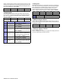
4.7 Input Speed
(001 to 255 X 30msec, default = 600ms)
The Input Speed defines how quickly the control panel responds to an open
zone detected on any hardwired input terminal (does not apply to
addressable motion detectors and door contacts). Set the Input Speed (001
to 255 X 30ms, default = 600ms):
[0961]
Input 01
[0973]
Input 13 (ATZ of Input 01)
[0962]
Input 02
[0974]
Input 14 (ATZ of Input 02)
[0963]
Input 03
[0975]
Input 15 (ATZ of Input 03)
[0964]
Input 04
[0976]
Input 16 (ATZ of Input 04)
[0965]
Input 05
[0977]
Input 13 (ATZ of Input 01)
[0966]
Input 06
[0978]
Input 14 (ATZ of Input 02)
[0967]
Input 07
[0979]
Input 15 (ATZ of Input 03)
[0968]
Input 08
[0980]
Input 16 (ATZ of Input 04)
4.8 EOL on Hardwire Zones
SECTION [3033]: OPTION [7]
(default = disabled) If detection devices connected to hardwired input
terminals use 1kΩ end of line resistors, enable option [7] in section [3033].
For details on using EOL resistors, refer to Addressable Zone Connections
on page 5 and Double Zone Connections on page 6.
4.9 Keypad Numbering
SECTIONS [2801] TO [2832]
Keypad Numbering identifies the keypad in the event buffer. The keypad is
assigned to a Keypad Number from 1 to 32 through the keypad's serial
number in sections [2801] to [2832].
EVO Control Panel 13
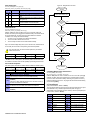
5
Remote Control Programming
5.1 Hardware Requirements
If the EVO48 System Includes:
MG-RTX3 Wireless Expansion Module And EVO641 / EVO641R keypad
Up to 96 remote controls can now be programmed into the EVO control
panel and configured using a master code or installer code.
[2911]
Template 12
(__/__)
(__/__)
[2912]
Template 13
(__/__)
(__/__)
[2913]
Template 14
(__/__)
(__/__)
[2914]
Template 15
(__/__)
(__/__)
If the EVO192 System Includes:
MG-RTX3 Wireless Expansion Module And EVO641 / EVO641R keypad
Up to 999 remote controls can now be programmed into the EVO control
panel and configured using a master code or installer code.
(1B) (C0) (00) (00)
future use
If the System Includes:
MG-RTX3 Wireless Expansion Module But does not include:EVO641 /
EVO641R keypad. Remote controls must be stored in the wireless
expansion module (32 remotes per MG-RTX3) by enabling option [1] in
section [3029].
Button 1
Button 2
Button 3
Button 2+3
MG-REM1
+
MG-REM2
+
Disarm
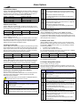
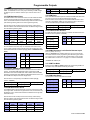
5.2 Remote Control Template
It is possible to set up to 16 different button templates which can then be
assigned to individual users. Each user is pre-programmed with a default
remote control button pattern: (1 B) (C 0) (template 1).
Default
(1 B) (C 0)
Section
Option
[2940]
Default button
Template
[2941]
Assign Button
Template
Utility
Key 1
Utility
Key 2
Disabled
Description
To select a button template as
the default template, enter (00)
to (15) representing button
templates in sections [2900] to
[2915].
To assign a button template to
a user, select user when
prompted, then enter (00) to
(15) representing button
templates in sections [2900] to
[2915].
Section
Template#
Button
Options
[2900]
Template 1
(__/__)
(__/__)
[2901]
Template 2
(__/__)
(__/__)
[2902]
Template 3
(__/__)
(__/__)
[2903]
Template 4
(__/__)
(__/__)
[2904]
Template 5
(__/__)
(__/__)
[2905]
Template 6
(__/__)
(__/__)
[2906]
Template 7
(__/__)
(__/__)
[2907]
Template 8
(__/__)
(__/__)
[2908]
Template 9
(__/__)
(__/__)
[2909]
Template 10
(__/__)
(__/__)
[2910]
Template 11
(__/__)
(__/__)
14 Reference & Installation Manual
Regular
Arm
Table 3: Template Entries
Entry
Disarm:
cannot be
modified
Entry
Function
[0]
Button Disabled
[8]
Function
[1]
Regular Arm
[9]
Panic 2
[2]
Stay Arm
A = [stay]
Panic 3
Utility Key 1
Panic 1
[3]
Instant Arm
B = [force]
[4]
Force Arm
C = [arm]
Utility Key 2
[5]
N/A
D = [disarm]
Utility Key 3
[6]
N/A
E = [byp]
Utility Key 4
[7]
N/A
F = [mem]
N/A
Keyswitch Programming
6
6.1 Keyswitch Numbering
2.
SECTIONS [0501] TO [0532]
Keyswitch Numbering allows you to assign any hardwired input in the
system to any of the 32 keyswitch zones in the control panel (see Figure
15). UL Note: Do not use Keyswitches in UL Listed systems.
6.3 Keyswitch Partition Assignment
Figure 15: Example of Keyswitch Numbering
Input Terminals
3 4 5 6 7
COMMUNICATION
CombusNETWORK
Zone Expansion Module
SN#: 34000041
1
2
Input Terminals
3 4 5 6
Serial#
020000A2
34000041
34000041
Sections [0601] to [0632]: Option [3]
When enabled, the keyswitch can only disarm assigned partitions. The type
of disarming is determined by the other Keyswitch Options selected.
8
6.4.2 Stay/Instant Disarm Option (Keyswitch)
Keyswitch C
Keyswitch B
Section
[0501]
[0502]
[0503]
7
Input 6
Input 2
Keyswitch A
Keyswitch
Zone #
Keyswitch A:
1=
Keyswitch B:
2=
Keyswitch C:
3=
Each keyswitch zone can be programmed with one or more options.
6.4.1 Disarm Only
8
Input 1
2
SECTIONS [0601] TO [0632]: SECOND DIGIT = 1 TO 8
Each keyswitch must be assigned to one partition.
6.4 Keyswitch Options
Control Panel
SN#: 020000A2
1
Enable option [4] in the section corresponding to the desired
keyswitch.
Input#
001
002
006
SECTIONS [0601] TO [0632]: OPTION [4]
When enabled, the keyswitch can only disarm assigned Stay or Instant
armed partitions. When option [4] is disabled, the keyswitch can disarm
partitions armed using any arming method.
6.4.3 Arm Only (Keyswitch)
SECTIONS [0601] TO [0632]: OPTION [5]
When enabled, the keyswitch can only arm assigned partitions. The type of
arming is determined by the other Keyswitch Options selected.
6.2 Keyswitch Definitions
6.4.4 Regular Arming (Keyswitch)
Keyswitch Definitions determine how a keyswitch is used.
SECTIONS [0601] TO [0632]: OPTION [6] TO [8]
With disabled, the arming option will be Regular arming.
6.2.1 Keyswitch Disabled
SECTIONS [0601] TO [0632]: FIRST
Disables keyswitch input.
DIGIT
=0
6.2.2 Momentary Keyswitch
6.4.5 Stay Arming (Keyswitch)
SECTIONS [0601] TO [0632]: OPTION [6]
Activating the keyswitch will Stay Arm the partition.
SECTIONS [0601] TO [0632]: FIRST DIGIT = 1
To arm or disarm a partition using the Momentary Keyswitch, turn on the
keyswitch for three seconds then turn it off.
6.4.6 Force Arming (Keyswitch)
6.2.3 Maintained Keyswitch
6.4.7 Instant Arming (Keyswitch)
SECTIONS [0601] TO [0632]: FIRST DIGIT = 2
To arm a partition using the Maintained Keyswitch, turn the switch from the
ON to the OFF position. Disarm it by setting the key on the ON position.
SECTIONS [0601] TO [0632]: OPTION [8]
This option is identical to Stay arming except that all armed zones will
become Instant Zones (see section 4.4.4 on page 10).
6.2.4 Generates a Utility Key Event on Open
SECTIONS [0601] TO [0632]: FIRST DIGIT = 3
To program a keyswitch to generate a Utility Key Event:
1.
2.
SECTIONS [0601] TO [0632]: OPTION [7]
Activating the keyswitch will force arm the selected partition.
Only one of the arming options (Stay, Force, Instant and Regular)
can be selected.
Program the Activation Event of a PGM output with the Utility Key
Event corresponding to the desired keyswitch (see PGM
Programming Table in the "EVO Programming Guide": Event Group
048).
Enable option [3] in the section corresponding to the desired
keyswitch.
6.2.5 Generates a Utility Key Event on Open and Close
SECTIONS [0601] TO [0632]: FIRST DIGIT = 4
A Utility Key Event can be generated whenever the keyswitch input is
opened or closed. The Utility Key Events increase from 32 to 64 events;
one event for each state.
When a keyswitch is defined with the Generate a Utility Key Event on Open
and Close option, the Keyswitch Partition Assignment and Keyswitch
Options are disabled. To program a keyswitch to generate a Utility Key
Event:
1. Program the Activation Event of a PGM output with the Utility Key
Event corresponding to the desired keyswitch (see PGM Programming
Table in the "EVO Programming Guide": Event Group 048).
EVO Control Panel 15
7
Arming and Disarming Options
7.1 Arming Follows Partition
7.9 Restrict Arming on Module Troubles
(default = disabled) A partition can be set to follow the arming and
disarming status of one or more partitions.
SECTION [3035]: OPTION [5]
(default = disabled) When is enabled, the control panel uses the same
Restrict Arming options for the modules connected to the combus.
Section:
Partition 1: [3121]
Partition 2: [3221]
Partition 3: [3321]
Partition 4: [3421]
Partition 5: [3521]
Partition 6: [3621]
Partition 7: [3721]
Partition 8: [3821]
Partition arms & disarms with:
Option [1] =
Partition 1
Option [2] =
Partition 2
Option [3] =
Partition 3
Option [4] =
Partition 4
Option [5] =
Partition 5
Option [6] =
Partition 6
Option [7] =
Partition 7
Option [8] =
Partition 8
7.2 Trouble Latch
SECTION [3033]: OPTION [6]
With the Trouble Latch feature disabled, when a trouble occurs and is
corrected, the trouble is automatically cleared and no longer displayed.
With the Trouble Latch feature enabled, the trouble will remain displayed
until it is manually cleared by the user. To clear the trouble, the user must
enter the trouble display and then exit the trouble display. For LCD and
LED keypads, press [CLEAR] to exit. For Grafica keypads, press the left
action key (Back) to exit.
Only troubles that have been corrected can be cleared. If a
trouble has not been corrected, it will continue to be displayed
even if the user tries to clear the trouble by using the method
described above.
7.3 Restrict Arming on Supervision Loss
SECTION [3034]: OPTION [4]
(default = disabled) When enabled, arming is restricted if a supervision
loss signal from the Magellan Wireless System MG-RTX3 is received.
7.4 Restrict Arming on Tamper
SECTION [3034]: OPTION [8]
(default = disabled) When enabled, the control panel prevents arming if it
detects a tamper on a zone or module (see section 8.5 on page 19).
Partitions will not arm until the Installer Code is entered and the tamper
trouble conditions are corrected.
7.5 Restrict Arming on AC Failure
SECTION [3035]: OPTION [1]
(default = disabled) When enabled, the control panel prevent arming if it
detects a loss of AC power.
7.6 Restrict Arming on Battery Failure
SECTION [3035]: OPTION [2]
(default = disabled) When enabled, the control panel prevents arming if it
detects a battery loss or if the battery voltage is less than 10.5V.
7.7 Restrict Arming on Bell or Auxiliary Failure
SECTION [3035]: OPTION [3]
(default = disabled) When enabled, the control panel prevents arming if:
• the bell or siren is disconnected
• the Bell Output has exceeded its current limits
• the Auxiliary Outputs have exceeded their current limits
7.10 Timed Auto-Arming
(default = disabled) The control panel arms the selected partition every day
at the time set (see section 7.10.1). A 60-second Exit Delay (default value)
triggers before the partition arms. It can be cancelled or postponed by
entering a valid access code. If zones are open, the control panel arms the
partition and considers all open zones as temporarily bypassed (except
24hr. zones). The control panel transmits the Auto-Arming report code
programmed in section [3910]. The control panel will transmit the Late to
Close report code programmed in section [3912]. Enable option [1] in the
desired section:
Partition 1: [3122] Partition 3: [3322] Partition 5: [3522] Partition 7: [3722]
Partition 2: [3222] Partition 4: [3422] Partition 6: [3622] Partition 8: [3822]
7.10.1 Auto-Arm Timer
Enter the time when the partition should arm in the desired section:
Partition 1: [3101] Partition 3: [3301] Partition 5: [3501] Partition 7: [3701]
Partition 2: [3201] Partition 4: [3401] Partition 6: [3601] Partition 8: [3801]
7.10.2 Postpone Auto-Arming
(default = 000) It is possible to postpone auto-arming for a preset amount of
time by entering a valid user code during the exit delay. The delay is set by
entering a number between 001 and 255 in the appropriate section. That
number represents for how many increments of 15 minutes the arming will
be postponed.
Partition 1: [3120] Partition 3: [3320] Partition 5: [3520] Partition 7: [3720]
Partition 2: [3220] Partition 4: [3420] Partition 6: [3620] Partition 8: [3820]
7.11 No Movement Auto-Arming
(default = disabled) If no movement occurs in a partition for the specified
period, the control panel will automatically arm that partition. The AutoArming Option determines the arming method (see section 7.12). The
control panel will transmit the No Movement report code programmed in
section [3913] upon arming. The control panel will always transmit the Late
to Close report code [3912]. Enable option [2] in the desired section:
Partition 1: [3122] Partition 3: [3322] Partition 5: [3522] Partition 7: [3722]
Partition 2: [3222] Partition 4: [3422] Partition 6: [3622] Partition 8: [3822]
7.11.1 No Movement Timer
(default = 000) Select the section corresponding to the desired partition and
program the time without movement necessary before the control panel will
arm and/or send the No Movement report code. If No Movement AutoArming is disabled, the control panel can still send the No Movement report
code. Enter the time period (001 to 255 x 5 minutes, 000 = disabled) when
the partition should arm in the desired section:
Partition 1: [3107] Partition 3: [3307] Partition 5: [3507] Partition 7: [3707]
Partition 2: [3207] Partition 4: [3407] Partition 6: [3607] Partition 8: [3807]
7.11.2 No Movement Schedule
7.8 Restrict Arming on TLM Failure
SECTION [3035]: OPTION [4]
(default = disabled) When enabled, the control panel can prevent arming if
it is unable to access the telephone line.
16 Reference & Installation Manual
It is possible to program the No-movement arming option for each partition
to follow a schedule. These schedules, which function like access
schedules, will ensure that No-Movement arming only occurs during these
specified periods and not at any moment when there is no movement.
When option [8] is enabled, access is permitted during the programmed
holidays (see section 15.8 on page 36).
No Movement Schedule
Partition 1: [3131] Partition 3: [3331] Partition 5: [3531] Partition 7: [3731]
Partition 2: [3231] Partition 4: [3431] Partition 6: [3631] Partition 8: [3831]
Option
Day
Option
7.17 One-Touch Features
(default = disabled) The One-Touch features can arm or disarm a partition,
access Bypass Programming, or display the Event Buffer by pressing and
holding a specific key for 2 seconds instead of entering an access code. If
the keypad is assigned to more than one partition, the feature must be
enabled in the corresponding partitions. Select the section corresponding to
the desired partition and enable or disable the desired options:
Day
Partition 1: [3125] Partition 3: [3325] Partition 5: [3525] Partition 7: [3725]
[1]
Sunday (S)
[5]
Thursday (T)
Partition 2: [3225] Partition 4: [3425] Partition 6: [3625] Partition 8: [3825]
[2]
Monday (M)
[6]
Friday (F)
[3]
Tuesday (T)
[7]
Saturday (S)
[4]
Wednesday (W)
[8]
Holidays (H)
7.12 Auto-Arming Options
(default = disabled) When using the Auto-Arming features (see section
7.10 and section 7.11), the control panel can Force arm or Stay arm the
partitions. To Auto-Arm using Stay arming, enable option [3] in the desired
section:
Partition 1: [3122] Partition 3: [3322] Partition 5: [3522] Partition 7: [3722]
Partition 2: [3222] Partition 4: [3422] Partition 6: [3622] Partition 8: [3822]
Option One-Touch Feature
One-Touch
Key
[1]
Regular Arming
[ARM]
[2]
Stay Arming
[STAY]
[3]
Instant Arming
[5]
[4]
Force Arming
[FORCE]
[5]
Stay/Instant Disarming
[DISARM]
[6]
Bypass Programming
[BYP]
[7]
Event Record Display
[7]
7.13 Switch To Stay Arming
If no Entry Delay zones are opened and closed during the Exit Delay after
Regular arming a partition, the control panel can switch from Regular
arming to Stay arming. Enable the option in the desired section:
7.18 Exit Delay
Partition 1: [3121] Option [1]
Partition 5: [3521] Option [5]
(default = 060) The Exit Delay is the amount of time users have to leave the
protected area before arming. It applies to all zones, except 24Hr Zones.
Program the Exit Delay from 001 to 255 seconds:
Partition 2: [3221] Option [2]
Partition 6: [3621] Option [6]
Partition 1: [3108] Partition 3: [3308] Partition 5: [3508] Partition 7: [3708]
Partition 3: [3321] Option [3]
Partition 7: [3721] Option [7]
Partition 2: [3208] Partition 4: [3408] Partition 6: [3608] Partition 8: [3808]
Partition 4: [3421] Option [4]
Partition 8: [3821] Option [8]
7.14 Always Force Arm when Regular Arming
(default = disabled) When enabled for a particular partition, the system will
Force arm that partition whenever Regular or Force arming is activated.
Stay and Instant arming are not affected by this feature. An event will be
generated for every zone bypassed in that manner. Another event will be
generated when the zone will be closed. Enable option [8] in the desired
section:
Partition 1: [3123] Partition 3: [3323] Partition 5: [3523] Partition 7: [3723]
Partition 2: [3223] Partition 4: [3423] Partition 6: [3623] Partition 8: [3823]
7.18.1 Exit Delay Termination
(default = enabled) The control panel can reduce the Exit Delay to 7
seconds when an Entry Delay zone is opened and closed during the delay.
Enable option [4] in the desired section:
Partition 1: [3122] Partition 3: [3322] Partition 5: [3522] Partition 7: [3722]
Partition 2: [3222] Partition 4: [3422] Partition 6: [3622] Partition 8: [3822]
7.18.2 No Exit Delay on Remote Arm
(default = enabled) When a user arms by using a remote control from the
Magellan Wireless System (MG-RTX3), the control panel will cancel the
Exit Delay and immediately arm the partition. Enable option [8] in the
desired section:
7.15 Auto Force on Stay Arming
Partition 1: [3125] Partition 3: [3325] Partition 5: [3525] Partition 7: [3725]
(default = disabled) When enabled for a particular partition, the system will
Force arm that partition whenever Stay arming is activated. An event will be
generated for every zone bypassed in that manner. Another event will be
generated when the zone will be closed. Enable option [4] in the desired
section
Partition 2: [3225] Partition 4: [3425] Partition 6: [3625] Partition 8: [3825]
Partition 1: [3126] Partition 3: [3326] Partition 5: [3526] Partition 7: [3726]
Partition 2: [3226] Partition 4: [3426] Partition 6: [3626] Partition 8: [3826]
7.18.3 Special Arming Exit Delay
(default = 060) This allows to set an exit delay in seconds for a special
arming. Special arming are any arming that do happen without interacting
with a keypad (i.e.: scheduled arming, keyswitch arming, WinLoad arming,
no movement arming, etc.)
Partition 1: [3130] Partition 3: [3330] Partition 5: [3530] Partition 7: [3730]
7.16 Follow Zone Switches to Entry Delay 2
Partition 2: [3230] Partition 4: [3430] Partition 6: [3630] Partition 8: [3830]
(default = enabled) When enabled and an Entry Delay zone is bypassed,
an armed Follow Zone (see section 4.4.3 on page 10) that opens without an
Entry Delay being triggered will switch to the partition’s Entry Delay 2.
Enable option [8] in the desired section:
7.19 Keypad Lock-out Feature
Partition 1: [3122] Partition 3: [3322] Partition 5: [3522] Partition 7: [3722]
Partition 2: [3222] Partition 4: [3422] Partition 6: [3622] Partition 8: [3822]
(default = 005) If a consecutive number of invalid codes are entered into a
keypad, the control panel can be set to lockout access from all the keypads
in the partition for a specified period. Program the number of consecutive
invalid codes from 001 to 255 (000 = disabled) into the desired section:
Partition 1: [3105] Partition 3: [3305] Partition 5: [3505] Partition 7: [3705]
Partition 2: [3205] Partition 4: [3405] Partition 6: [3605] Partition 8: [3805]
EVO Control Panel 17
(default = 015) Program the duration of the keypad lockout from 001 to 255
minutes into the desired section. Programming 000 into these sections will
not lockout the keypad, the control panel will transmit the Keypad Lockout
report code programmed in section [3937].
Partition 1: [3106] Partition 3: [3306] Partition 5: [3506] Partition 7: [3706]
Partition 2: [3206] Partition 4: [3406] Partition 6: [3606] Partition 8: [3806]
7.21 Ring-back
After disarming the system, the control panel can warn the user that there
was an alarm and that it may be dangerous to enter by having the keypad
beep 10 times and/or by squawking the bell 10 times. The user should
leave immediately and contact the monitoring station from a secure
location. Select the section that corresponds to the desired partition and
enable or disable the desired option (off = disabled) (default = disabled):
Partition 1: [3124] Partition 3: [3324] Partition 5: [3524] Partition 7: [3724]
7.20 Bell Squawk
The control panel can activate the bell output briefly causing the bell or
siren to squawk to alert users that a partition is being armed, disarmed or
that an Entry or Exit Delay was triggered. Enable or disable the desired
option (off = disabled):
Partition 2: [3224] Partition 4: [3424] Partition 6: [3624] Partition 8: [3824]
[7]
Bell Ring-back
Bell or siren emits 10 squawks
[8]
Keypad Ring-back
Keypad emits 10 beeps
Partition 1: [3124] Partition 3: [3324] Partition 5: [3524] Partition 7: [3724]
Partition 2: [3224] Partition 4: [3424] Partition 6: [3624] Partition 8: [3824]
7.22 Maximum Bypass Entries
Option Bell Squawk on:
(default = 000) The Maximum Bypass Entries feature limits the number of
zones that can be bypassed in each partition. Enter any value between 001
and 096 (000 = no limit).
[1]
Disarming
[2]
Arming
[3]
Auto-Arming
[4]
Exit Delay
[5]
Entry Delay
[6]
Remote Arming/
Disarming
Description
Emits 2 squawks upon disarming
(default = disabled)
Emits 1 squawk upon arming
(default = disabled)
Emits 1 squawk every second for 60s before
Auto-Arming a partition. Emits a series of 3
squawks every second for 10s before arming
(default = disabled)
Emits 1 squawk every second during the Exit
Delay. Emits a series of 3 squawks every
second during the final 10 seconds of the
Exit Delay (default = disabled)
Emits 1 squawk every second during the
Entry Delay (default = disabled)
Emits 1 squawk upon arming and 2 squawks
upon disarming with a remote control (using
the Magellan Wireless System, MG-RTX3
(default = enabled)
18 Reference & Installation Manual
Partition 1: [3115] Partition 3: [3315] Partition 5: [3515] Partition 7: [3715]
Partition 2: [3215] Partition 4: [3415] Partition 6: [3615] Partition 8: [3815]
7.23 Display “Bypass” If Armed
SECTION [3033]: OPTION [5]
(default = enabled) When enabled, the keypads will not display that zones
have been bypassed while the system is armed.
8
Alarm Options
8.1 Bell/alarm Output
(default = only option [1] enabled) When an alarm condition is detected in
a partition, the control panel can trigger the on-board BELL output enabling
any bells or sirens connected to it. In section [3032] enable the option to
enable the bell output in the desired partition (off = disabled):
Partition 1: Option [1]
Partition 2: Option [2]
Partition 3: Option [3]
Partition 4: Option [4]
ON
OFF
ON
ON
Partition 5: Option [5]
Partition 6: Option [6]
Partition 7: Option [7]
Partition 8: Option [8]
8.2 Bell Cut-off Timer
(default = 004) After an audible alarm, the bell or siren will stop once the
partition is disarmed or when the Bell Cut-Off Timer has elapsed. Enter any
value between 001 and 255 minutes:
Partition 1: [3113] Partition 3: [3313] Partition 5: [3513] Partition 7: [3713]
Partition 2: [3213] Partition 4: [3413] Partition 6: [3613] Partition 8: [3813]
8.2.1 No Bell Cut-Off on Fire Alarm
SECTION [3030]: OPTION [2]
(default = disabled) The control panel can disable the Bell Cut-Off Timers
when alarms are generated from zones defined as Standard or Delayed
Fire Zones (see section 4.4 on page 10). The BELL output will remain
enabled until a user disarms the partition in alarm.
When disarmed: Generates Trouble Only
The control panel displays Zone Fault in the Trouble Display
and transmits the defined report code (see section 9.2 on page
22).
When armed: Follows Zone Alarm Type
The control panel follows the zone’s alarm type (see section
4.6.5 on page 12).
When disarmed: Generates Audible Alarm
The control panel displays Zone Fault in the Trouble Display,
transmits the defined report code (see section 9.2 on page 22),
and generates an audible alarm.
When armed: Follows Zone Alarm Type
The control panel follows the zone’s alarm type (see section
4.6.5 on page 12).
8.3.1 Supervision Bypass Options
SECTION [3034]: OPTION [3]
(default = disabled) When enabled in section [3034], the Wireless
Transmitter Supervision Options will follow the zone's bypass definition.
The control panel will not perform any action if a supervision loss occurs on
a bypassed zone. When disabled, it will ignore the bypass definition and will
follow the option set in section 8.3.
8.4 Police Code Timer
(default = 000) The control panel re-verifies the zone status during an alarm
at a programmed rate once the Bell Cut-Off Timer and the Recycle Delay
elapse. If open zones remain, the control panel will regenerate the alarm.
Enter the number of times from 001 to 255 (000 = no limit) in one armed
period that the control panel will re-verify the zone status:
(default = 000) If an alarm condition occurs on a zone, the control panel
generates an alarm and triggers the Police Code Timer. The Police Code
programmed in [3934] will only be sent if one of the following conditions
occurs during the delay:
1. An alarm occurs on another zone.
2. The zone in alarm restores and reoccurs.
Key in the desired 3-digit delay value (001 to 255 minutes, 000 = disabled)
into the section corresponding to the desired partition:
Partition 1: [3117] Partition 3: [3317] Partition 5: [3517] Partition 7: [3717]
Partition 1: [3118] Partition 3: [3318] Partition 5: [3518] Partition 7: [3718]
Partition 2: [3217] Partition 4: [3417] Partition 6: [3617] Partition 8: [3817]
Partition 2: [3218] Partition 4: [3418] Partition 6: [3618] Partition 8: [3818]
8.2.3 Recycle Delay
Refer to Intellizone Options on page 12 to set it up so that a police code is
only generated on Zone Crossing.
8.2.2 Recycle Alarm Rate
(default = 000) The Recycle Delay is the amount of time the control panel
will wait after the Bell Cut-off occurs before re-verifying the zone status.
Program the Recycle Delay from 001 to 255 minutes (000 = disabled):
Partition 1: [3116] Partition 3: [3316] Partition 5: [3516] Partition 7: [3716]
Partition 2: [3216] Partition 4: [3416] Partition 6: [3616] Partition 8: [3816]
8.3 Wireless Transmitter Supervision Options
SECTION [3034]: OPTIONS [1] AND [2]
When the control panel detects a Supervision Loss, the control panel can
generate an alarm and/or trouble, unless the Wireless Transmitter
Supervision Option is disabled.
The Supervision feature must be enabled in the Magellan Wireless
System (MG-RTX3) for this feature to function.
8.5 Tamper Recognition Options
SECTION [3034]: OPTIONS [5] AND [6]
When the control panel detects a tamper or wire fault on a zone or on an
expansion module, the control panel can generate an alarm and/or trouble,
as shown in the table below.
[5] [6] Description
OFF OFF
OFF
ON
ON
OFF
ON
ON
[1] [2] Description
OFF OFF
OFF
ON
Disabled (default):
Displays zone open on the keypads, but will not generate an
alarm or trouble.
Not permitted on UL systems.
Generates Trouble Only (when armed or disarmed):
The control panel displays Zone Fault in the Trouble Display
and transmits the defined report code (see section 9.2 on page
22).
Disabled (default):
Displays zone open on the keypads, but will not generate an
alarm or trouble.
Not permitted on UL systems.
Generates Trouble Only (when armed or disarmed):
The control panel displays Zone Fault in the Trouble Display and
transmits the defined report code (see section 9.2 on page 22).
When disarmed: Generates Trouble Only
The control panel displays Zone Fault in the Trouble Display and
transmits the defined report code (see section 9.2 on page 22).
When armed: Follows Zone Alarm Type
The control panel follows the zone’s alarm type (see section
4.6.5 on page 12).
When disarmed: Generates Audible Alarm
The control panel displays Zone Fault in the Trouble Display,
transmits the defined report code (see section 9.2 on page 22),
and generates an audible alarm.
When armed: Follows Zone Alarm Type
The control panel follows the zone’s alarm type (see section
4.6.5 on page 12).
EVO Control Panel 19
8.5.1 Tamper Bypass Options
SECTION [3034]: OPTION [7]
(default = enabled) When enabled in section [3034], the control panel will
ignore the zone’s bypass definition and will follow the option set in section
8.5 (page 19) if a tamper or wire fault occurs on a bypassed zone. When
disabled, Tamper Recognition follows the zone’s bypass definition. This
means that the control panel will not perform any action if a tamper or wire
fault occurs on a bypassed zone.
8.6 Keypad Panic Options
(default = disabled) The control panel can generate an alarm (audible, fire
or report only) by pressing the keypad Panic key(s). Refer to the table
below for the keypad Panic keys. In the section that corresponds to the
desired partition, enable or disable options [1] through [6]:
Partition 1: [3123] Partition 3: [3323] Partition 5: [3523] Partition 7: [3723]
Partition 2: [3223] Partition 4: [3423] Partition 6: [3623] Partition 8: [3823]
Option Feature
Press and Hold 2 Seconds:
LCD keypads: Keys [1] and [3] simultaneously
[1]
Panic 1*
Grafica keypads: The
key
LCD keypads: Keys [4] and [6] simultaneously
[2]
Panic 2*
Grafica keypads: The
key
LCD keypads: Keys [7] and [9] simultaneously
[3]
Panic 3
Grafica keypads: The
key
Option Alarm Type
[4]
Panic 1:*
[5]
Panic 2:*
[6]
Panic 3:
ON
OFF
ON
OFF
ON
OFF
= Audible
= Report Only
= Audible
= Report Only
= Fire
= Report Only
Report Only
The keypad emits a single confirmation beep and transmits the report code.
Audible Alarm
The control panel activates the BELL output until a user cancels the alarm or
when the Bell Cut-Off Timer elapses .
Fire Alarm
Same as audible operation, except that the bell/siren output will be pulsed.
* UL Note: For UL Listed systems, all emergency non-medical and auxiliary
panic alarms will be report only.
20 Reference & Installation Manual
9
Event Reporting
Figure 16: Event Reporting
Dialing Enabled/Disabled
Section [3036]
Option [3]
Partition 1
Reporting Account Number 1
3 or 4 digits (0-F) in Section [3061]
Partition 2
Reporting Account Number 2
3 or 4 digits (0-F) in Section [3062]
Related Features
Delay Before Alarm Transmission: [3055]
Pager Format Delay Transmission: [3057]
Recent Closing Delay
Sections [3109], [3209], [3309], [3409],
[3509], [3609], [3709] and [3809]
Partition 3
Reporting Account Number 3
3 or 4 digits (0-F) in Section [3063]
Partition 4
Reporting Account Number 4
3 or 4 digits (0-F) in Section [3064]
Partition 5
Reporting Account Number 5
3 or 4 digits (0-F) in Section [3065]
Report Disarm Options
Option [7]: Sections [3123], [3223], [3323],
[3423], [3523], [3623], [3723] and [3823]
Partition 6
Reporting Account Number 6
3 or 4 digits (0-F) in Section [3066]
Report Zone Restore Options
Section [3037] Option [8]
Partition 7
Reporting Account Number 7
3 or 4 digits (0-F) in Section [3067]
Partition 8
Reporting Account Number 8
3 or 4 digits (0-F) in Section [3068]
Power Failure Report Delay: [3058]
Reporting Account Numbers
Monitoring Station
Telephone Numbers
1 to 4 (32 digits)
Sections [3071] to [3074]
Dialing sequences for Arm/Disarm Report Codes
Partition 1 = [3127] Partition 5 = [3527]
Partition 2 = [3227] Partition 6 = [3627]
Partition 3 = [3327] Partition 7 = [3727]
Partition 4 = [3427] Partition 8 = [3827]
Event Call Direction
Defines to which Monitoring
Station Telephone Number
each specific group of events
will be reported.
Dialing sequences for Alarm/Restore Report Codes
Partition 1 = [3128] Partition 5 = [3528]
Partition 2 = [3228] Partition 6 = [3628]
Partition 3 = [3328] Partition 7 = [3728]
Partition 4 = [3428] Partition 8 = [3828]
Dialing sequences for Tamper/Restore Report Codes
Partition 1 = [3129] Partition 5 = [3529]
Partition 2 = [3229] Partition 6 = [3629]
Partition 3 = [3329] Partition 7 = [3729]
Partition 4 = [3429] Partition 8 = [3829]
Dialing sequence for
Trouble/Restore Report Codes: [3080]
Auto Test Report: [3040] and [3041]
Alternate Dial
Section [3037] Option [6]
[1] = Call Monitoring Telephone 1
[2] = Call Monitoring Telephone 2
[3] = Call Monitoring Telephone 3
[4] = Call Monitoring Telephone 4
[5] = Backup on Telephone 1
[6] = Backup on Telephone 6
[7] = Backup on Telephone 7
[8] = Backup on Telephone 8
For each section (dialing sequence)
enable up to 4 monitoring station
telephone numbers and 1 backup
telephone number. The numbers are
dialed sequentially from 1 to 4
followed by the backup number.
This sequence will continue until
each number has been dialed at
least once.
Dialing sequence for
System Special Report Codes: [3081]
Pulse
Reporting Formats
Section [3070]
First digit= MSTN #1
Second digit=MSTN #2
Third digit=MSTN #3
Fourth digit=MSTN #4
MSTN = Monitoring Station
Telephone Number
[0]
Ademco Slow
[1]
Silent Knight Fast
[2]
Sescoa
DTMF
(Tone)
[3]
Ademco Express
[7]
Pager
[6]
SIA FSK
[5]
Ademco Contact I.D.
Program 2-digit (00-FF)
report codes into:
Sections [0201] to [0296]
Sections [0701] to [0732]
Sections [0801] to [0832]
Sections [2001] to [2099]
Sections [2101] to [2199]
Sections [3900] to [3991]
Maximum Dialing Attempt
Section [3056]
Delay Between Dialing Attempts
Section [3054]
Sections [4030] to [4037]
Manual & Automatic programming of report codes, refer to:
1) Ademco Contact ID and SIA FSK under Reporting Formats on page 24
2) Auto Report Code Programming on page 26
EVO Control Panel 21
9.1 Reporting Enabled
SECTION [3036]: OPTION [3]
(default = disabled) If enabled, the control panel verifies if a report code
was programmed in the section corresponding to event that happened. If a
report code is programmed, the control panel dials the monitoring station
telephone number. When the monitoring station answers, the control panel
transmits the system account code and the programmed report code.
9.2 Report Codes
Report codes are 2-digit or 1-digit hexadecimal value. The Ademco Slow,
Silent Knight, Sescoa and Pager Formats support 1-digit report codes. The
transmission is defined by these two items: Reporting Formats (see
section 9.7 on page 24) and Event Call Direction (see section 9.8 on page
24). If you are using the Ademco CID or SIA formats, an Auto Report Code
Programming feature is available (see section 9.17 on page 26).
9.2.1 Zone Alarm and Alarm Restore Report Codes
[0400]: FIRST AND SECOND BRACKETS
SECTIONS [0201] TO [0296]: FIRST AND SECOND BRACKETS
The first set of 2 digits in the sections refer to the Alarm Report Codes that
identify which zones generated an alarm. The second set of 2 digits refer to
the Alarm Restore Report Codes when a zone closes or once the bell has
cut-off (see section 8.2 on page 19). Refer to Zone Restore Report Options
in (see section 9.16 on page 25).
SECTION
[3900]
Cold Start
control panel re-starts after complete
shutdown (total power loss)
[3901]
Warm Start
control panel resets due to sudden
problem other than power loss
[3902]
Test Report
report generated automatically
(see section 9.14)
[3903]
Listen-In to Follow
Listen-In module attempts to start a
Listen-In session
[3904]
WinLoad Login
Request
communication attempted between
WinLoad and control panel (Callback only)
[3905]
WinLoad Log Off
control panel ends communication with
WinLoad
[3906]
Installer In
installer enters programming mode
[3907]
Installer Out
installer exits programming mode
[3908] to [3909]
Future Use
9.2.8 Special Arming Report Codes
When the partition arms using a special arming feature, the control panel
can send the report code identifying how the system was armed.
[3910]
Auto-Arming
when Auto-Arming (see section 7.10 on page
16)
[0400]: THIRD AND FOURTH BRACKETS
SECTIONS [0201] TO [0296]: THIRD AND FOURTH BRACKETS
The third set of 2 digits refer to the Tamper Report Codes. The fourth set of
2 digits refer to the Tamper Restore Report Codes.
[3911]
PC Arming
system armed using WinLoad or NEware
software
[3912]
Late to Close
when Auto-Arming (see section 7.10 on page
16)
9.2.3 Keyswitch Arming
[3913]
No Movement
when No Movement Auto-Arming
(see section 7.11 on page 16)
[3914]
Partial Arming
when partitions are Stay, Instant or Force armed
or armed with bypassed zones
[3915]
Quick Arming
partitions armed with a One-Touch Arming
feature (see section 7.17 on page 17)
[3916]
Early to Close
partition armed before Arming Report Schedule
(see section 9.3.1 on page 23)
[3917]
Late to Close
partition armed after Arming Report Schedule
(see section 9.3.1 on page 23)
[3918]
Remote Arm
partition armed with the InTouch Voice-Assisted
Arm/Disarm Module (APR3-ADM2)
[3919]
Closing
Delinquency
Partition hasn’t been armed before the
programmed Closing Delinquency Timer
elapsed (see section 9.18 on page 26).
9.2.2 Tamper and Tamper Restore Report Codes
SECTION
SECTIONS [0701] TO [0732]
Each section from [0701] to [0732] corresponds to a keyswitch from 1 to
32. The control panel can send the report code to the monitoring station
identifying which keyswitch was used to arm. It will not send report codes
for keyswitches that are defined with the PGM Activation definition.
9.2.4 Keyswitch Disarming
SECTIONS [0801] TO [0832]
Each section from [0801] to [0832] corresponds to a keyswitch from 1 to
32. The control panel can send a report code to the monitoring station
identifying which keyswitch was used to disarm. It can transmit the report
codes every time a partition is disarmed or only following an alarm. It will
not send report codes for keyswitches that are defined with the PGM
Activation definition.
9.2.5 Access Codes Arming
SECTIONS [2001] TO [2099]
A report code can be programmed for each user access code from 01 to 98
in sections [2001] to [2098]. User access codes from 99 to 999 use a
common report code in section [2099]. The control panel can send the
report code identifying which access code was used to arm the system.
9.2.6 Access Codes Disarming
SECTIONS [2101] TO [2199]
A report code can be programmed for each user access code from 01 to 98
in sections [2101] to [2198]. User access codes from 99 to 999 use a
common report code programmed in section [2199].The control panel can
send the report code to the monitoring station identifying which access
code was used to disarm the system. It can be transmitted when a partition
is disarmed or only following an alarm. Also, see section 9.15 on page 25.
9.2.9 Special Disarming Report Codes
When using one of the special disarming features listed below, the control
panel can send the report code identifying how the system was disarmed.
Also, refer to Disarm Reporting Options in section 9.15 on page 25.
[3920]
Cancel Auto-Arm
partition disarms during the Auto-Arm’s delay
(see section 7.10 on page 16)
[3921]
Quick Disarm
partition disarms using One-Touch Disarming
feature (see section 7.17 on page 17)
[3922]
PC Disarm
system disarmed using WinLoad or NEware
software
[3923]
PC Disarm after
Alarm
system disarmed using WinLoad or NEware
software after an alarm occurs
[3924]
Cancel Alarm
indicates that an alarm was cancelled even
though the system was not armed when the
alarm occurred.
[3925]
Future Use
[3926]
Early to Open
partition disarmed before Disarming
Schedule (see section 9.3.1 on page 23)
[3927]
Late to Open
partition disarmed after Disarming Schedule
(see section 9.3.1 on page 23)
9.2.7 Special System Reporting Codes
When the system generates one of the following events, the control panel
can send the report code to the monitoring station identifying the event:
22 Reference & Installation Manual
[3928]
Remote Disarm
partition disarmed with InTouch VoiceAssisted Arm/Disarm Module (APR3-ADM2)
9.2.10 Special Alarm Report Codes
[3930]
[3931]
[3932]
[3933]
9.2.12 System Trouble Restore Codes
[3970]
TLM1 Restored
[3981]
Module Tamper Restored
[3971]
AC Restored
[3982]
ROM Check Error Restored
[3972]
Battery Restored
[3983]
Module TLM Restored
[3973]
Auxiliary Supply
Restored
[3984]
Module Fail to Communicate
Restored
Emergency Panic
(non-medical)
the panic keys [1] and [3] were pressed
(see section 8.6 on page 20)
Auxiliary Panic
the panic keys [4] and [6] were pressed
(see section 8.6 on page 20)
[3974]
Bell Output Restored [3985]
Printer Fault Restored
Fire Panic
the panic keys [7] and [9] were pressed
(see section 8.6 on page 20)
[3975]
Clock Loss Restored [3986]
Module AC Failure Restored
[3976]
Fire Loop Restored
[3987]
Module Battery Restored
Recent Closing
an alarm is generated within the Recent
Close Delay (see section 9.10 on page 25)
[3977]
Future Use
[3988]
Module Auxiliary Restored
[3978]
Future Use
[3989]
Future Use
[3979]
Future Use
[3990]
Wireless Transmitter Battery
Restored
[3980]
Bus Fault Restored
[3991]
Wireless Module Supervision
Restored
[3934]
Police Code
Confirmation of an alarm condition occurred
during the Police Code Timer’s delay (see
section 8.4 on page 19).
[3935]
Auto Zone
Shutdown
the control panel stops regenerating alarms
on a zone during the same armed period
(see section 4.6.1 on page 11)
[3936]
Duress
a Duress enabled access code is keyed in
(see Appendix 3: Keypad Installation
Instructions on page 44)
[3937]
Keypad Lockout
too many invalid codes entered
(see section 7.19 on page 17)
If the Telephone Line Monitoring (see section 10.1) is disabled, the control panel will
not transmit the TLM report code.
9.3 Report Arming and Disarming
These features identify when partitions should be armed or disarmed. It
allow the control panel to report changes from the schedule.
9.3.1 Arming and Disarming Report Schedules
9.2.11 System Trouble Codes
[3941]
AC Failure
AC power not detected. Also, see Power
Fail Report Delay in section 9.11
[3942]
Battery Failure
battery is disconnected or the battery
voltage is less than or equal to 10.5V
[3943]
Auxiliary Supply
the aux power supply’s current is greater
than or equal to 1.1A
Bell Output
bell output is disconnected or the current
is greater than or equal to 3A
[3944]
[3945]
Clock Loss
panel time lost (see section 13.17)
[3946]
Fire Loop Trouble
tamper on a Fire Zone (see section 4.4)
[3947] TO [3949]
Future Use
[3950]
Bus Fault
a module was removed from the combus
[3951]
Module Tamper
tamper/wire fault on module (not a motion
detector) on the combus
[3952]
ROM Check Error
on-board Read-Only Memory trouble
[3953]
Module TLM
TLM failure detected on Listen-In Module
(DGP-LSN4)
[3954]
Module Fail to
Communicate
DGP2-DVAC failed to communicate with
the monitoring station
[3955]
Printer Fault
Printer Module detected an error
[3956]
Module AC Failure no AC power detected on a module
[3957]
Module Battery
Failure
battery on a module is disconnected or the
battery voltage is low
[3958]
Module Auxiliary
Failure
the AUX output on a module has
exceeded current limits
[3959]
Future Use
[3960]
Wireless Transmitter Low Battery
[3961]
Wireless Module
this report code is global unless using the
Supervision Failure Contact ID or SIA reporting formats
the battery voltage is low on a wireless
transmitter
[3962] to [3964]
Future Use
[3965]
Fail to Com 1
Phone Number 1 failed to communicate*
[3966]
Fail to Com 2
Phone Number 2 failed to communicate*
[3967]
Fail to Com 3
Phone Number 3 failed to communicate*
[3968]
Fail to Com 4
Phone Number 4 failed to communicate*
* No “Fail to Communicate” for Pager telephone numbers
Arming and Disarming Report Schedules identify the days and times that a
partition should be armed and disarmed. Each schedule consists of 2
programmable time periods called Intervals that determine the time span
and days when the partition should be armed or disarmed (see Figure 17).
Schedules are enabled when they are programmed.
Figure 17: Example of an Arming and a Disarming Report Schedule
Program the Start Time and End Time according to the 24-hour clock and
enable the options representing the desired Days for the desired partition.
When option [8] is enabled, access is permitted during the programmed
holidays (see section 15.8 on page 36).
Arming Report Schedule
Partition 1: [3102] Partition 3: [3302] Partition 5: [3502] Partition 7: [3702]
Partition 2: [3202] Partition 4: [3402] Partition 6: [3602] Partition 8: [3802]
Disarming Report Schedule
Partition 1: [3103] Partition 3: [3303] Partition 5: [3503] Partition 7: [3703]
Partition 2: [3203] Partition 4: [3403] Partition 6: [3603] Partition 8: [3803]
EVO Control Panel 23
Day
9.6 Account Number Transmission
[1]
Sunday (S)
[5]
Thursday (T)
[2]
Monday (M)
[6]
Friday (F)
[3]
Tuesday (T)
[7]
Saturday (S)
[4]
Wednesday (W)
[8]
Holidays (H)
SECTION [3035]: OPTION [6]
(default = Partition Account #) When enabled, the account number
corresponding to the MSTN that was dialed will be sent regardless of which
partition the report originated from. When disabled, the account number
that is sent to the monitoring station corresponds to the partition where the
event originated, regardless of which MSTN is dialed.
Option
Day
Option
9.3.2 Arming/Disarming Schedule Tolerance Window
(default = 000) The Arming/Disarming Schedule Tolerance Window
lengthens the partition’s Arming/Disarming Schedule for some users. User
access codes with Add Tolerance Windows to Schedules enabled have the
number of minutes programmed in these sections added before and after
the corresponding partition’s schedule. Enter any value between 001 and
255 to determine Arming/Disarming Schedule Tolerance Window in
minutes.
Partition 1: [3104] Partition 3: [3304] Partition 5: [3504] Partition 7: [3704]
Partition 2: [3204] Partition 4: [3404] Partition 6: [3604] Partition 8: [3804]
The Arming/Disarming Schedule Tolerance Window applies to the Arming and
Disarming Report Schedules only (section 9.3.1). The Arming/Disarming Schedule
Tolerance Window does not apply to Access Schedules (section 15.6 on page 36).
9.7 Reporting Formats
SECTION [3070]
The control panel can use a number of different reporting formats. Each
monitoring station phone numbers should be programmed with the same
reporting format unless they are combined with a Pager format. The first
digit represents the reporting format (see Table 6) used for Monitoring
Station Telephone Number 1, the second digit, Monitoring Station
Telephone Number 2, etc.
Compatible Digital Alarm Communication Receivers (DACRs):*
• Sur-Gard DRL2A
• Ademco 685
• Osborne Hoffman Quick Alert II
9.4 Monitoring Station Phone Number
SECTIONS [3071] TO [3074]
The control panel can dial up to 4 different monitoring station telephone
numbers. Sections [3071] to [3074] represent monitoring station telephone
numbers 1 through 4. Enter any digit up to a maximum of 32.
Functions
Table 4: Special Telephone Number Keys
Key
*
[STAY]
#
[FORCE]
Switch to Tone Dialing (T)
Wait for second dial tone (W)
[ARM]
[DISARM]
[#]
(Press the key until the
desired letter/symbol
appears)
4-second pause (P)
[BYP]
Insert
[MEM]
—
Delete
[TRBL]
—
Delete from cursor to end
[ACC]
Left action key (Clear)
Table 6: Reporting Formats*
0 = Ademco slow (1400Hz, 1900Hz, 10BPS)
4 = Contact ID Pager
1 = Silent Knight fast (1400Hz, 1900Hz, 20BPS) 5 = Ademco Contact ID
2 = Sescoa (2300Hz, 1800Hz, 20BPS)
6 = SIA FSK
3 = Ademco Express (DTMF 4+2)
7 = Pager
* UL Note: Installer must verify the compatibility with of the DACR. Use
listed compatible DACRs.
9.7.1 Standard Pulse Formats
The control panel can use the Ademco slow, Silent Knight fast and Sescoa
standard pulse reporting formats (see Table 6).
9.7.2 Ademco Express
The Ademco Express is a high-speed reporting format that communicates
2-digit (00 to FF) report codes. The Ademco Express does not use the
Contact ID Report Codes.
9.7.3 Contact ID Pager
9.5 Account Number
SECTIONS [3061] TO [3068]
(default = 000) All report codes are preceded by a 3- or 4-digit Account
Number to ensure correct identification of system events. Account
Numbers can be any hexadecimal value from 0 to F.
The control panel will transmit a Contact ID report instead of a user
generated numerical code to a pager. The Contact ID report code will come
from either the Automatic Report Code List on page 40 or the Contact ID
Report Code List on page 42.
9.7.4 Ademco Contact ID
Table 5: Account Numbers
Section [3035],
Section [3035],
Section Account Number
option [6] = disabled option [6] = enabled
[3061] Account Number 1 Partition 1
MSTN 1
[3062] Account Number 2 Partition 2
MSTN 2
[3063] Account Number 3 Partition 3
MSTN 3
[3064] Account Number 4 Partition 4
MSTN 4
[3065] Account Number 5 Partition 5
N/A
[3066] Account Number 6 Partition 6
N/A
[3067] Account Number 7 Partition 7
N/A
[3068] Account Number 8 Partition 8
N/A
Only the SIA format supports the [0] = 0 digit in its account numbers. Account
numbers that use other reporting formats do not support the [0] = 0 digit. Enter the
[STAY] = A digit in its place. When using the SIA Format, and the Account Number
Transmission (see section 9.6 on page 24) corresponds to the partition, the control
panel only uses the Partition 1 Account Number programmed in section [3061], but
the report code includes the partition number.
Ademco Contact ID is a fast communicator format that uses tone reporting.
To program the report codes, use the 2-digit hexadecimal values from the
Contact ID Report Codes List in the “EVO Programming Guide”. Enter 00 to
disable reporting or FF to use the default report code from the Automatic
Report Code List in the “EVO Programming Guide”. To program a set of
default Contact ID codes, refer to section 9.17 on page 26.
9.7.5 SIA FSK
SIA FSK is a fast communicator format that uses tone reporting. To
program the report codes, enter 00 to disable reporting or any other value
to use the default report code from the Automatic Report Code List in the
“EVO Programming Guide”. To program a set of default SIA FSK codes,
refer to Auto Report Code Programming on page 26.
9.7.6 Pager Reporting Format
Using this format allows the control panel to transmit report codes to a
pager. A pound symbol “#” is automatically generated after the report code.
9.8 Event Call Direction
Event groups can be programmed to dial up to four monitoring station
telephone numbers with one used as a backup. The numbers are dialed
24 Reference & Installation Manual
sequentially, skipping any disabled numbers and stopping once all selected
telephone numbers have been reached. If the control panel still fails to
report to a monitoring station telephone number after reaching the
Maximum Dialing Attempts (see section 9.8.1 on page 25), the control
panel will dial the selected backup telephone number. For each section
enable or disable the options:
code programmed into section [3933]. Enter any value between 001 and
255 to determine Recent Close Delay in seconds.
Partition 1: [3109] Partition 3: [3309] Partition 5: [3509] Partition 7: [3709]
Partition 2: [3209] Partition 4: [3409] Partition 6: [3609] Partition 8: [3809]
9.11 Power Failure Report Delay
Troubles and Restore Troubles: [3080]
Special System, Arming, Disarming and Alarm Reporting: [3081]
Access Code and Keyswitch Arming and Disarming
Partition 1: [3127] Partition 3: [3327] Partition 5: [3527] Partition 7: [3727]
Partition 2: [3227] Partition 4: [3427] Partition 6: [3627] Partition 8: [3827]
SECTION [3058]
(default = 030) The control panel will delay the transmission of the AC
Failure report code programmed into section [3941] by the period
programmed into section [3058]. Enter any value between 001 and 255 to
determine Power Failure Report Delay in minutes.
9.12 Power Failure Restore Report Delay
Partition 2: [3228] Partition 4: [3428] Partition 6: [3628] Partition 8: [3828]
SECTION [3060]
(default = 030) The control panel will delay the transmission of the AC
Failure Restore report code programmed into section [3972] by the period
programmed into section [3060]. Enter any value between 001 and 255 to
determine Power Failure Restore Report Delay in minutes.
Tampers and Tamper Restores
9.13 Repeat Pager Report Code Transmission
Zone Alarms and Alarm Restores
Partition 1: [3128] Partition 3: [3328] Partition 5: [3528] Partition 7: [3728]
Partition 1: [3129] Partition 3: [3329] Partition 5: [3529] Partition 7: [3729]
SECTION [3059]
{default = 000) This feature re-sends the report code as specified.
Partition 2: [3229] Partition 4: [3429] Partition 6: [3629] Partition 8: [3829]
9.14 Auto Test Report
(default = only option [1] enabled)
Option Call:
Option Call (select one only):
[1]
Telephone Number 1
[5]
Backup on Number 1
[2]
Telephone Number 2
[6]
Backup on Number 2
[3]
Telephone Number 3
[7]
Backup on Number 3
[4]
Telephone Number 4
[8]
Backup on Number 4
SECTION [3037]: OPTIONS [3] AND [4] AND
SECTIONS [3040], [3041], [3042] AND [3043]
The control panel can transmit the test report code programmed into
section [3902] every hour or after a period of time.
OFF OFF
Auto Test
Report
Period
(default)
OFF ON
Timed Test
Transmission
when Armed/
Disarmed
ON OFF
Hourly Test
Transmission
ON
Timed and
Hourly Test
Transmission
9.8.1 Maximum Dialing Attempts*
SECTION [3056]
(default = 008) The number (001 to 255, 000 = 8 attempts) programmed
into section [3056] determines how many tries before proceeding to the
next number. Also refer to section 9.8.3.
* UL Note: For UL Listed systems, the maximum dialing attempts must be set
to 5 to 10 attempts between the EVO’s two telephone lines.
9.8.2 Delay Between Dialing Attempts
SECTION [3054]
(default = 020) This delay can be set from 001 to 127 seconds.
9.8.3 Alternate Dialing Option
SECTION [3037]: OPTION [6]
(default = disabled) When enabled, the control panel dials the selected
backup telephone number after every failed attempt to contact a monitoring
station telephone number. When disabled, the control panel dials the
backup telephone number after the Maximum Dialing Attempts (see section
9.8.1) to one monitoring station telephone number fail.
9.9 Pager Delay
SECTION [3057]
(default = 020) When using the Pager Reporting Format (see section 9.7.6),
the control panel will wait for the delay period programmed into section
[3057] before uploading the report codes to the pager. Enter any value
between 001 and 127 to determine Pager Delay in seconds.
ON
After the number programmed (000 to 255 days,
default = 000) in section [3040], the control panel
transmits a report code at the time (00:00 to 23:59,
default = 00:00) programmed in section [3041].
When disarmed: The control panel transmits the
code at regular intervals. Program the number of
minutes (000 to 255, default = 060) between
transmissions in section [3043].
When armed: The control panel transmits the test
report code at regular intervals. Program the
number of minutes (000 to 255, default = 005)
between each transmission in section [3042].
The control panel will transmit the test report code
every hour on the minute value programmed in
section [3041] (the last two digits). Note that the
first two digits of section [3041] will be ignored.
The test report code will be transmitted when any
of the conditions of the second and third options
listed above (options [3] = OFF and [4] = ON /
options [3] = ON and [4] = OFF) are met.
9.15 Disarm Reporting Options
(default = disabled) When disabled, the control panel sends the Disarming
Report Codes (see section 9.2 on page 22) every time the partition is
disarmed. When enabled, the control panel sends the Disarming Report
Codes to the monitoring station only when the partition is disarmed
following an alarm. Select the section that corresponds to the desired
partition and enable or disable option [7]:
Partition 1: [3123] Partition 3: [3323] Partition 5: [3523] Partition 7: [3723]
Partition 2: [3223] Partition 4: [3423] Partition 6: [3623] Partition 8: [3823]
9.10 Recent Close Delay
9.16 Zone Restore Report Options
(default = 000) If an alarm is generated within the programmed period after
arming the partition, the control panel will transmit the Recent Close report
SECTION [3037]: OPTION [8]
(default = disabled) When disabled, the control panel sends the Zone
Alarm Restore report codes to the monitoring station when the Bell Cut-Off
Timer elapses (see section 8.2) or when the alarm is disarmed. When
EVO Control Panel 25
enabled, the control panel sends the Zone Alarm Restore report codes (see
section 9.2) to the monitoring station as soon as the zone returns to normal
(zone closure) or upon disarming.
9.17 Auto Report Code Programming
When using either the Contact ID or SIA Reporting Formats (see section
9.7 on page 24), the control panel can automatically program a set of
default report codes. The Contact ID Reporting Format can be modified
using the manual programming method (see section 9.7.4 & section 9.7.5
on page 24) to program remaining report codes or to change some of the
defaults. Enter any of the following sections to set the indicated report
codes with the default values (FF) from the Automatic Report Codes List in
the "EVO Programming Guide":
Section Description
[4030]
Resets all the report code sections to 00 (cleared).
[4031]
Sets all the report code sections to FF (defaults).
Section Sets to Defaults (FF)
Reset Sections
[4032]
Zone Alarm and Restore Report Codes
Tamper and Restore Report Codes
[0201] to [0296]
[4033]
Keyswitch Arming Report Codes
Keyswitch Disarming Report Codes
Access Code Arming Report Codes
Access Code Disarming Report Codes
[0701] to [0732]
[0801] to [0832]
[2001] to [2099]
[2101] to [2199]
[4034]
Special System Report Codes
[3900] to [3909]
[4035]
Special Arming Report Codes
Special Disarming Report Codes
[3910] to [3919]
[3920] to [3929]
[4036]
Special Alarm Report Codes
[3930] to [3939]
[4037]
Trouble and Restore Report Codes
[3940] to [3991]
9.18 Closing Delinquency Timer
(default = 000; disabled) When a partition in the system is disarmed, the
control panel will start the corresponding partition’s Closing Delinquency
Timer. If the Closing Delinquency Timer elapses before the partition is
armed again, EVO will transmit a “Closing Delinquency” report code to the
monitoring station. Enter a value from 001 to 255 days into the appropriate
section. Enter 000 to disable the Closing Delinquency Timer.
Partition 1: [3119] Partition 3: [3319] Partition 5: [3519] Partition 7: [3719]
Partition 2: [3219] Partition 4: [3419] Partition 6: [3619] Partition 8: [3819]
26 Reference & Installation Manual
10
Dialer Options
10.1 Telephone Line Monitoring
10.6 Bell On Communication Fail
SECTION [3036]: OPTIONS [1] AND [2]
When enabled, the system verifies the existence of the main telephone line
once every second. After each successful test, the Status LED on the
control panel flashes briefly. A line test failure occurs when the TLM detects
less than 3 volts for the period defined by the TLM Fail Timer (see section
10.1.1). If the line test fails, the control panel will generate one or more
conditions as defined by the TLM settings below, until it detects the
telephone line again. When the dialer detects a telephone ring, the TLM
test stops for 1 minute.
SECTION [3036]: OPTION [8]
(default = disabled) When enabled and the control panel fails to
communicate with the monitoring station when the partition is armed, the
control panel can enable the BELL output.
[1]
[2] Feature
OFF OFF
Disabled
ON
OFF
Trouble Only
OFF
ON
ON
ON
When the line test fails
TLM disabled (default) .
The Communicator trouble appears in the
Trouble Display.
The Communicator trouble appears in the
Alarm when
Trouble Display. If the partition is armed, the
Armed
control panel generates an alarm.
The Communicator trouble appears in the
Trouble Display. The control panel switches
Silent Alarms
become Audible any triggered Silent Alarm zones or Silent
panic alarms to an audible alarm.
10.7 Keypad Beep on Successful Arm or Disarm Report
SECTION [3037]: OPTION [5]
(default = disabled) When enabled and a user arms or disarms a partition,
the keypad emits a beep tone to confirm that the monitoring station
received the arming or disarming report code.
10.8 Dial Tone Delay
SECTION [3037]: OPTION [7]
(default = disabled)
[7]
ON
If no dial tone is present, dialer hangs up after 32 secs.
[7]
OFF
If no dial tone is present, force dials after 3 secs.
If more time is required, insert a 4-second pause into the desired telephone
number sequence (see section 9.4).
10.1.1 TLM Fail Timer
SECTION [3053]
(default = 016) If the TLM does not detect the existence of the main
telephone line for the time programmed in this section, the control panel will
generate the condition(s) defined by the TLM options (see section 10.1).
Enter any value between 016 and 255 (value is X2 seconds) into section
[3053]. Entering a value between 000 and 016 will set the TLM Fail Timer
to 32 seconds.
10.2 Tone/Pulse Dialing
SECTION [3036]: OPTION [4]
(default = enabled)
[4]
ON
Tone/DTMF format
[4]
OFF
Pulse dialing format
10.3 Pulse Ratio
SECTION [3036]: OPTION [5]
(default = enabled) When using Pulse dialing (see section 10.2), select one
of two Pulse Ratios. If the selected pulse ratio does not provide adequate
results, try the other one.
[5]
ON
North American pulse ratio of 1:1.5
[5]
OFF
European pulse ratio of 1:2
10.4 Busy Tone Detection
SECTION [3036]: OPTION [6]
(default = enabled) When enabled, the control panel immediately hangs up
if it receives a busy signal when it dials an outside number.
10.5 Switch To Pulse
SECTION [3036]: OPTION [7]
(default = disabled) When is enabled, the control panel switches from tone
dialing to pulse dialing on the fifth attempt to report events to the monitoring
station. The control panel continues to use pulse dialing until it establishes
communication. When the control panel switches to another monitoring
station telephone number, it returns to tone dialing and switches back to
pulse dialing on the fifth attempt.
EVO Control Panel 27
11
VDMP3 Voice Module
11.3 VDMP3 Setup Instructions
Attach support
pin to EVO
panel and
VDMP3
Step
Enable
Functions
2
Telephone
Numbers
Connect 307USB /
CONV4USB (WinLoad /
NEware) to SERIAL
11.1 VDMP3 Installation Instructions
Step
1
Install
English
• Power down the EVO control panel.
• Install the VDMP3 directly onto the EVO control panel’s SERIAL and
DIALER connectors as shown in "VDMP3 Installation Instructions".
• If using a 307USB or CONV4USB, connect to the COM PORT
connector as shown in "VDMP3 Installation Instructions".
• Power up the EVO control panel.
11.2 Feature activation (PGMs)
Using the VDMP3, it is possible to activate the PGM utility keys or PGM
groups that are programmed in the EVO panel.
VDMP3 feature numbers do not necessarily correspond to EVO utility key
numbers.
3
Enable
Numbers
[3090]
[3091]
to
[3098]
[3133]
to
[3833]
4
Answering
Machine
Override
[3052]
5
Enable
Features
(PGM)
English
Select the following options to enable voice reporting and
arm/disarm function.
1
VDMP3
Connect VDMP3
to EBUS and
DIALER
EVO
section
[1] Arm/disarm
[2] Voice reporting
(default 1 and 2 ON)
Program up to 8 telephone numbers which will be called in
sequence in the event of an alarm. Telephone numbers
should be programmed in priority sequence as the VDMP3
will start with telephone number 1. For extra key functions,
see Special Telephone Number Keys on page 24.
[3091] Telephone number 1
[3095] Telephone number 5
[3092] Telephone number 2
[3096] Telephone number 6
[3093] Telephone number 3
[3097] Telephone number 7
[3094] Telephone number 4
[3098] Telephone number 8
Choose which telephone numbers will be enabled for each
partition in your system. Options [1] to [8] represent
telephone numbers 1 through 8.
(Default: Telephone number 1 is enabled for all partitions.)
[3133] Partition 1 [1] to [8]
[3533] Partition 5 [1] to [8]
[3233] Partition 2 [1] to [8]
[3633] Partition 6 [1] to [8]
[3333] Partition 3 [1] to [8]
[3733] Partition 7 [1] to [8]
[3433] Partition 4 [1] to [8]
[3833] Partition 8 [1] to [8]
If the VDMP3 uses a telephone line that is connected to an
answering machine or service, the Answering Machine
Override must be programmed. The value programmed in
section [3052] represents the delay period that the VDMP3
will wait between the first and second call. The user must
call the VDMP3, hang up, and then call back within the
value programmed in section [3052]. The module then
overrides the answering machine or service by picking up
the line on the first ring.
000 to 225 seconds (default 008)
Note: Changing these values will also affect PC
communication via WinLoad software.
Features in this section correspond to utility key PGMs in the
EVO control panel. For more information, see Feature
Activation (PGMs).
[3087]
Options [1] to [8] represent features 1 to 8 (default: OFF)
[3088]
After the VDMP3 dials a phone number, it waits the
programmed delay period before sending the voice
message. The value programmed in section [3088]
represents the length of time the VDMP3 will wait before
playing the message.
000 to 127 seconds (default 003)
6
Message
Delay
For example:
VDMP3
Feature
EVO Utility Key
VDMP3
Feature
EVO Utility Key
Feature 1 ON
Utility Key 1
Feature 5 ON
Utility Key 9
Feature 1 OFF
Utility Key 2
Feature 5 OFF
Utility Key 10
Feature 2 ON
Utility Key 3
Feature 6 ON
Utility Key 11
Feature 2 OFF
Utility Key 4
Feature 6 OFF
Utility Key 12
Feature 3 ON
Utility Key 5
Feature 7 ON
Utility Key 13
Feature 3 OFF
Utility Key 6
Feature 7 OFF
Utility Key 14
Feature 4 ON
Utility Key 7
Feature 8 ON
Utility Key 15
Feature 4 OFF
Utility Key 8
Feature 8 OFF
Utility Key 16
If the utility key in the EVO panel is programmed with a timer, the
VDMP3 will not recognize PGM deactivation when the set timer
elapses. As a result, the VDMP3 may indicate that the PGM is ON
when actually the timer has elapsed and the PGM is in fact OFF
28 Reference & Installation Manual
7
Message
Repetitions
8
Delay
Before Next
Number
9
Ring
Counter
Set the number of times the VDMP3 will play the voice
message.
[3089]
000 to 008 repetitions (default 008)
Set the delay before the VDMP3 attempts to dial the next
number on the list.
[3054]
[3051]
000 to 255 seconds (default 020)
Note: Changing these values will also affect regular
reporting to monitoring station.
Set the number of rings the VDMP3 will wait before the call
is answered.
000 to 008 rings (default 008)
Note: Changing these values will also affect PC
communication via WinLoad software.
12
Programmable Outputs
The control panel provides a maximum of 100 mA to PGM1 to PGM4.
PGM5 is a 5A/28Vdc N.O./ N.C. relay output. Activating a PGM changes
it’s state from open to closed or closed to open. Refer to section 2.8 on
page 2.
PGM 4
[0944]
[0945]
[0946]
[0947]
PGM 5
[0954]
[0955]
[0956]
[0957]
12.5 PGM Timer
12.1 PGM Activation Event
The PGM Activation Event determines which event will activate the PGM.
The Event Group specifies the event, the Feature Group identifies the
source, and the Start # and End # sets the range within the Feature Group
(see PGM Programming Table in the "EVO Programming Guide").
Enter the sections that correspond to the Event Group, Feature Group,
Start # and End # of the desired PGM and enter the desired 3-digit number
from the PGM Programming Table:
Event Group Feature Group
When the PGM Deactivation Option is enabled, the PGM Timer determines
how many seconds or minutes the PGM remains activated.
Enter the section that corresponds to the desired PGM and enter a value
from 001 to 255 (default = 005). The value entered is either in seconds or
minutes as determined by the PGM Time Base Selection:
PGM 1: [0918]
PGM 2: [0928]
PGM 4: [0948]
PGM 5: [0958]
PGM 3: [0938]
Start #
End #
12.5.1 PGM Time Base Selection
The PGM Time Base Selection determines whether the PGM Timers are in
minutes or seconds (default = seconds):
PGM 1:
[0910]
[0911]
[0912]
[0913]
PGM 2:
[0920]
[0921]
[0922]
[0923]
PGM 3:
[0930]
[0931]
[0932]
[0933]
PGM 4:
[0940]
[0941]
[0942]
[0943]
PGM 5:
[0950]
[0951]
[0952]
[0953]
PGM 1: [0919]
Option
PGM 2: [0929]
[2]
ON
Minutes
PGM 3: [0939]
[2]
OFF
Seconds
12.2 PGM Deactivation Option
PGM 4: [0949]
Once the PGMs are activated, they can deactivate when another event
occurs or after a period of time. Enter the section that corresponds to the
desired PGM and enable or disable option [1] (default = PGM Deactivation
Event):
PGM 5: [0959]
PGM 1: [0919]
Option
Feature
PGM 2: [0929]
[1]
ON
PGM Timer
PGM 3: [0939]
[1]
OFF
PGM Deactivation Event
PGM 4: [0949]
[4]
ON
Normally Closed
PGM 5: [0959]
[4]
OFF
Normally Open
Feature
12.6 PGM1 Becomes a 2-wire Smoke Detector Input*
SECTION [3030]: OPTION [1]
(default = disabled) When enabled, PGM1 acts as a zone input for twowire smoke detectors. When programming Zone Numbering (see section
4.2 on page 10), the control panel will recognize PGM1 as input number
255. Please refer to section 2.16.1 on page 7 for connection information.
* UL Note: Not verified by UL.
12.7 PGM Test Mode
Entering sections [0901] to [0903] activates the corresponding PGM for 8
seconds to verify if the PGM is functioning as desired.
12.3 Flexible PGM Deactivation Option
The PGM Deactivation Option must be set to PGM Timer for this feature to
function. The Flexible PGM Deactivation Option uses both the PGM
Deactivation Event and the PGM Timer. When enabled, and if the PGM is
activated, it will deactivate when either the PGM Deactivation Event occurs
or the PGM Timer elapses, whichever happens first.
PGM 1: [0901]
PGM 2: [0902]
PGM 4: [0904]
PGM 5: [0905]
PGM 3: [0903]
12.8 PGM Initial Status
Use this option to set the initial state for the PGM.
Enter the section corresponding to the PGM and enable option [3]
(default = disabled):
PGM 1: [0919]
Option
PGM 1: [0919]
PGM 2: [0929]
PGM 2: [0929]
[4]
ON
Normally Closed
PGM 4: [0949]
PGM 5: [0959]
PGM 3: [0939]
[4]
OFF
Normally Open
PGM 3: [0939]
12.4 PGM Deactivation Event
Feature
PGM 4: [0949]
The PGM Deactivation Event determines which event will return the PGM
to its original state. The Event Group specifies the event, the Feature Group
identifies the source, and the Start # and End # determine the range within
the Feature Group.
PGM 5: [0959]
Enter the sections that correspond to the Event Group, Feature Group,
Start # and End # of the desired PGM and enter the desired 3-digit number
from the PGM Programming Table.
Event Group Feature Group
Start #
End #
PGM 1:
[0914]
[0915]
[0916]
[0917]
PGM 2:
[0924]
[0925]
[0926]
[0927]
PGM 3:
[0934]
[0935]
[0936]
[0937]
EVO Control Panel 29
13
System Settings and Commands
13.1 Hardware Reset
A Hardware Reset sets sections [0001] to [3991] to default. Only the Panel
ID, PC Password, PC Telephone Number and Event Buffer are not reset.
The Installer Code Lock prevents Hardware Reset.
1. Make sure the Installer Code Lock is disabled
2. Press and hold the Reset and Aux buttons for 3 seconds
3. The panel will be reset to defaults
13.2 Software Reset
Performing a software reset will set certain parameters to default values or
program certain sections with a set of pre-defined values. To reset:
1. Enter Panel Programming Mode (see section 3.4).
2. Enter section [4049] to unlock software reset.
3. Enter the 4-digit [SECTION] of the software reset you wish to perform.
4. For every other section your want to reset, you will have to unlock
software reset.
[4040]
Resets the programmable sections from [0001] to [3991] to
default (even if Installer Code Lock is enabled) except: Event
Buffer, Panel ID, PC Password, PC Telephone Number and Zone,
Door, Partition and User Labels (see section 14.4 on page 34).
[4041]
Resets the System Master Code to 123456.
[4042]
Resets all Zone Programming sections from [0001] to [0196],
[0201] to [0296] and [0961] to [0984] to default.
[4043]
Resets the Access Control sections, except Door Labels (see
section 13.25 on page 32), from [2201] to [2712] to default.
[4044]
Resets all User Access Code Programming sections from [1001]
to [1999] and [2001] to [2199] to default. User Labels (see
section 14.4 on page 34) will not be reset.
[4045]
Resets all control panel settings from [3020] to [3043] and from
[3900] to [3991] and all the Dialer sections from [3051] to [3081].
[4046]
Resets all Partition Settings, except Partition Labels (see section
13.25 on page 32), from [3101] to [3831] to default.
[4047]
Resets Keyswitch Programming sections from [0501] to [0832]
and all Programmable Outputs sections from [0901] to [0939] to
default.
[4048]
Entering this section resets the User Labels from the User
Access Codes, the Zone Labels from [0301] to [0396], Door
Labels from [2301] to [2332], Partition Labels [3100], [3200],
[3300], [3400], [3500], [3600], [3700] and [3800] to default.
[4049]
Select the schedule followed for the Daylight Savings Time adjustment.
Canada/United States/Mexico/
00 St-Johns/Bahamas/Turks and
Caicos
01 Cuba
02 Brazil
03 Chile
04 Falkland Islands
05 Paraguay
European Union/United
06
Kingdom/Greenland
South Australia/Victoria/
08 Australian Capital Territory/
New South Wales
07
Russia and surrounding
countries
09 Tasmania/Lord Howe Island
10 New-Zealand/Chatham
11
Tonga
12 Iraq/Syria
13 Israel (TBC)
14 Lebanon/Kirgizstan
15 Palestine
16 Egypt
17 Namibia
Canada/United States 2007
18
(default)
19 New Zealand
13.6 Battery Charge Current
SECTION [3030]: OPTION [5]
Depending on the battery’s capacity, enable or disable the option:
[5]
ON
850mA
[5]
OFF
350mA (default)
A 40VA transformer is required when selecting the 850mA battery charge current, a
20VA transformer may damage the system.
13.7 Combus Speed
SECTION [3030]: OPTION [8]
In large installations, set the speed to High. If you are experiencing
communication troubles, set the speed to Normal or install a Hub (APR3HUB2). The control panel will restart when a change is made
[8]
ON
High Speed
[8]
OFF
Normal Speed (default)
Please note that when the combus speed is changed the following
will occur and is considered normal operation:
Entering this section will unlock software reset for sections [4040]
to [4048].
• The message COMM. TROUBLE CALL SERVICE will be
displayed on keypads connected to the combus.
• The AC and STATUS LEDs will begin to alternately flash and all
operations on the system will be suspended for approximately
one minute while the system reconfigures.
Do not remove power from the control panel.
13.3 Installer Code Lock
13.8 Transmit Zone Status on Serial Port
SECTION [3001]
(default = 000) Enter 147 into section [3001] to lock all programming. When
147 is programmed, performing a hardware reset as described in section
13.1 will not affect the current panel settings. To remove the Installer Lock,
enter 000 into section [3001].
SECTION [3035]: OPTION [7]
When enabled, the control panel will transmit zone status information
through the serial port. Use this when there are devices or software
connected to the serial port like WinLoad.
13.4 Daylight Savings Time
13.9 Serial Port Baud Rate
SECTION [3030]: OPTION [3]
(default = enabled) When enabled, the control panel adjusts the system's
clock (time) for daylight saving changes.
SECTION [3035]: OPTION [8]
Adjust depending on the baud rate set in WinLoad or NEware:
13.5 Daylight Savings Time Schedule
SECTION [3022]
(default = 18)
30 Reference & Installation Manual
[8]
ON
57,600 baud
[8]
OFF
38,400 baud (default)
If communication between the control panel and the computer is
experiencing difficulty at 57,600 baud, especially over long
distances reduce the baud rate of the software to 38,400 baud.
13.10 Partitioning
13.14 Locate Module
SECTION [3031]: OPTIONS [1] TO [8]
(default = partition 1 enabled) The control panel can provide up to eight
completely independent partitions. Most features and options can be
independently set for each partition. All zones, keyswitch zones, user codes
and system modules are assigned to specific partitions. The EVO48 only
has 4 partitions.
SECTION [4002]
To locate a specific module on the combus, key in the module's serial
number into section [4002]. The LED on the module flashes until the serial
number is entered or the module’s tamper or unlocate switch is pressed.
[1]
Partition 1
[3]
Partition 3
[5]
Partition 5
[7]
Partition 7
[2]
Partition 2
[4]
Partition 4
[6]
Partition 6
[8]
Partition 8
13.15 Module Programming
SECTION [4003]
To program a module, enter section [4003] to enter Module Programming
Mode (see section 3.5 on page 8), and enter the module's serial number. To
exit, press the [CLEAR] key until Normal Mode is displayed.
13.10.1 Panel Partition Assignment
SECTION [3020]
(default = 00) The control panel will report system events as originating
from one or all enabled partitions. The System Troubles can only be viewed
through the partitions enabled in this section. Enter a 2-digit decimal
number from 01 to 08 which represent partitions 1 to 8. Enter 00 to disable
this feature.
13.11 Shabbat Feature
SECTION [3030]: OPTION [4]
(default = disabled) When enabled, addressable detectors and keypads in
the system no longer display system status through the LCD and/or LEDs
between noon Friday and midnight Saturday. Normal operation is reinstated Sunday at 12:00:01a.m. A user can access all the usual
commands and features during the Shabbat period by pressing a key or by
entering their access code (depending on how Confidential Mode is
configured in the keypad). When no actions have occurred for two minutes,
the Shabbat feature will re-activate. During the Shabbat period:
• the LCD keypads only display the date and time
• the backlight is disabled
• the LED indicators on modules are disabled
13.16 Module and Label Broadcast
SECTION [4004]
Module Broadcast
To copy the contents of the programming sections from one module to
another, enter the serial number of the source module in section [4004],
enter the serial numbers of all the destination modules and press [ACC] or
the center action key (Start).
Label Broadcast
Copy the User Labels, Zone Labels (sections [0301] to [0396]), the Door
Labels (sections [2301] to [2332]) and the Partition Labels (sections
[3100], [3200], [3300], [3400], [3500], [3600], [3700] and [3800]) to all the
modules in the system that support these labels. To transmit the labels, in
section [4004], enter the control panel’s serial number. From the
Destination screen, do not enter a serial number and press [ACC] if using an
LCD keypad or the center action key (Start) if using a Grafica keypad.
The Module and Label Broadcast feature will only work when a module is
broadcasting its data to a module or to modules of the same type and model number.
13.17 System Date & Time
The System Date and Time is programmed through the User Menu.
13.12 Installer Function Keys
Press and hold the [0] key and key in the [INSTALLER CODE] to access the
installer functions and then:
For LCD keypads: Press the key indicated in the list below that
corresponds to the function you wish to activate.
For Grafica keypads: Press the center action key (Options), highlight the
desired function and then press the center action key (Ok).
[STAY]
TEST REPORT: Sends the Test Report report code programmed
in section [3902] to the monitoring station.
CALL WINLOAD: Dials the PC telephone number programmed
[FORCE]
in section [3010] to communicate using WinLoad.
[ARM]
ANSWER WINLOAD: Forces the control panel to answer a call
made by the monitoring station that is using WinLoad.
[DISARM]
CANCEL COMMUNICATION: Cancels all communication with
the monitoring station or WinLoad until the next reportable event.
[MEM]
INSTALLER TEST MODE: Perform walk tests where the bell or
siren squawks once when a zone opens and twice when it
closes. Press [MEM] again to exit. Partitions cannot be armed if
the Installer Test Mode is enabled.
[TRBL]
START MODULE SCAN: Verifies the status of modules on the
combus. The LCD Keypads display the serial number of each
module connected to the combus.
[ACC]
START VOLTMETER READING (EVO641 only): Verifies if the
combus is supplying enough power at the keypad’s location.
13.13 Module Reset
SECTION [4001]
To reset a module connected to the combus to its default values, key in the
module's serial number into section [4001].
13.18 Quick Module Scanning
SECTION [4005]
After entering the section, the control panel will scan all addresses
assigned to modules. If any missing modules are detected (i.e. detector
removed from the combus), the control panel will erase the module's serial
number, removing the module from the control panel's memory.
13.19 Module Scanning
SECTION [4006]
After entering the section, the control panel will scan all addresses on the
combus. If any missing modules are detected (i.e. detector
removed from the combus), the control panel will erase the module's serial
number, removing the module from the control panel's memory.
If new modules are detected, the serial number will be entered in the
control panel’s memory.
13.20 Serial Number Viewing
SECTION [4000]
Enter section [4000] to view the serial number of the control panel and all
the modules on the combus. The firmware version of some modules will be
displayed as well (e.g. (XXXXXXXX) VXX.XX).
For LCD Keypads: The keypad will display the control panel’s serial
number. Use the [S] and [T] keys to scroll.
For Grafica Keypads: The keypad will display the control panel’s serial
number. Press the center action key (Next) to scroll.
13.21 Power Save Mode
SECTION [3033]: OPTIONS [4]
(default = enabled) When enabled and the control panel is running on the
backup battery, the control panel can set all keypads into Power Save
Mode. The keypad's backlight and LEDs are disabled until a key is pressed,
an alarm occurs or an Entry Delay is triggered.
EVO Control Panel 31
13.22 Auto Trouble Shutdown
SECTION [3021]
(default = 00) If a trouble occurs more than the number programmed, the
control panel stops reporting the trouble. Enter a value between 01 and 15,
(00 = disabled). Each trouble has its own counter that is reset at midnight.
13.23 No AC Fail Display
SECTION [3030]: OPTION [6]
(default = disabled) When enabled, the control panel will not display the
AC Failure as a trouble. When an AC Failure occurs with this option
enabled:
• the AC LED will extinguish
• the AC Failure report code will be reported.
• the trouble will not appear in the Trouble Display
• the keypad will not beep to indicate the trouble
13.24 Multiple Action Feature
SECTION [3033]: OPTION [1]
(default = disabled) When enabled, users will remain in the User Menu
after entering their access code. With option [1] off, the control panel will
exit the User Menu after every action.
Table 8: Numeric and Alphanumeric keys
Numeric
Alphanumeric
Key
Press key
one time
Press key
one time
Press key
two times
Press key
three times
[0]
[1]
[2]
[3]
[4]
[5]
[6]
[7]
[8]
[9]
0
1
2
3
4
5
6
7
8
9
--A
D
G
J
M
P
S
V
Y
--B
E
H
K
N
Q
T
W
Z
--C
F
I
L
O
R
U
X
Table 9: Special Characters Catalogue
032
048
064
080
096
112
128
144
160
176
192
208
224
240
033
049
065
081
097
113
129
145
161
177
193
209
225
241
034
050
066
082
098
114
130
146
162
178
194
210
226
242
035
051
067
083
099
115
131
147
163
179
195
211
227
243
036
052
068
084
100
116
132
148
164
180
196
212
228
244
037
053
A069
085
101
117
133
149
165
181
197
213
229
245
038
054
070
086
102
118
134
150
166
182
198
214
230
246
039
055
071
087
103
119
135
151
167
183
199
215
231
247
040
056
072
088
104
120
136
152
168
184
200
216
232
248
041
057
073
089
105
121
137
153
169
185
201
217
233
249
042
058
074
090
106
122
138
154
170
186
202
218
234
250
043
059
075
091
107
123
139
155
171
187
203
219
235
251
044
060
076
092
108
124
140
156
172
188
204
220
236
252
045
061
077
093
109
125
141
157
173
189
205
221
237
253
046
062
078
094
110
126
142
158
174
190
206
222
238
254
047
063
079
095
111
127
143
159
175
191
207
223
239
255
13.25 System Labels
The existing label displayed on the LCD screen can be modified to suit the
installation’s needs. Each label contains a maximum of 16 characters.
To re-program the System Label, enter the desired section and use Table 7,
Table 9 and Table 8 (page 32) to modify the label. For other languages,
refer to Table 10 to Table 14 on page 33. For instructions on how to enter
letters and special characters for the Grafica keypad, refer to “Grafica’s
Online Manual”. A complete “Grafica Online Manual” is available on our
website at paradox.com.
Zone Labels: Sections [0301] to [0396] represent Zones 01 to 96.
Door Labels: Sections [2301] to [2332] represent Doors 01 to 32.
Partition Labels:
Partition 1: [3100] Partition 3: [3300] Partition 5: [3500] Partition 7: [3700]
Partition 2: [3200] Partition 4: [3400] Partition 6: [3600] Partition 8: [3800]
Table 7: Keys
Press
Feature
Description
[STAY]
Insert Space
Inserts a blank space in the cursor’s position
[FORCE]
Delete
Deletes the character or blank space found
at the cursor’s position
[ARM]
Delete Until the
End
Deletes all characters and spaces to the
right of the cursor and at the cursor's position
[DISARM]
Numeric or
Alphanumeric
Switches from numeric keys to alphanumeric
keys and vice versa (see Table 8)
[BYP]
Lower or Upper
Case
Switches the case setting from lower to
upper case and vice versa
Special
Characters
The cursor will turn into a flashing black
square. Enter the 3-digit number that
represents the desired symbol (see Table 9
on page 32, Table 13 on page 33 and
Table 14 on page 33).
[MEM]
32 Reference & Installation Manual
Table 10: Hebrew Keypad Letter Assignment
Table 11: Russian Keypad Letter Assignment
Table 14: Russian Special Characters Catalogue
Table 12: Greek Keypad Assignment
Key
Press key once
Press key twice
#
&
*
0
2
6
%
[1]
[2]
[3]
[4]
[5]
[6]
[7]
[8]
$
'
3
.
4
7
;
Press key three
times
)
<
+
/
1
5
(
9
Table 13: Hebrew Special Characters Catalogue
032
048
064
080
096
112
160
176
192
208
224
240
033
049
065
081
097
113
161
177
193
209
225
241
034
050
066
082
098
114
162
178
194
210
226
242
Table 15: Greek Special Characters Catalogue
035
051
067
083
099
115
163
179
195
211
227
243
036
052
068
084
100
116
164
180
196
212
228
244
037
053
069
085
101
117
165
181
197
213
229
245
038
054
070
086
102
118
166
182
198
214
230
246
039
055
071
087
103
119
167
183
199
215
231
247
040
056
072
088
104
120
168
184
200
216
232
248
041
057
073
089
105
121
169
185
201
217
233
249
042
058
074
090
106
122
170
186
202
218
234
250
043
059
075
091
107
123
171
187
203
219
235
251
044
060
076
092
108
124
172
188
204
220
236
252
045
061
077
093
109
125
173
189
205
221
237
253
046
062
078
094
110
126
174
190
206
222
238
254
047
063
079
095
111
127
175
191
207
223
239
255
016
032
048
064
080
096
112
128
144
160
176
192
208
224
240
017
033
049
065
081
097
113
129
145
161
177
193
209
225
241
018
034
050
066
082
098
114
130
146
162
178
194
210
226
242
019
035
051
067
083
099
115
131
147
163
179
195
211
227
243
020
036
052
068
084
100
116
132
148
164
180
196
212
228
244
021
037
053
A069
085
101
117
133
149
165
181
197
213
229
245
022
038
054
070
086
102
118
134
150
166
182
198
214
230
246
023
039
055
071
087
103
119
135
151
167
183
199
215
231
247
024
040
056
072
088
104
120
136
152
168
184
200
216
232
248
025
041
057
073
089
105
121
137
153
169
185
201
217
233
249
026
042
058
074
090
106
122
138
154
170
186
202
218
234
250
027
043
059
075
091
107
123
139
155
171
187
203
219
235
251
028
044
060
076
092
108
124
140
156
172
188
204
220
236
252
029
045
061
077
093
109
125
141
157
173
189
205
221
237
253
030
046
062
078
094
110
126
142
158
174
190
206
222
238
254
031
047
063
079
095
111
127
143
159
175
191
207
223
239
255
EVO Control Panel 33
14
Access Codes
14.1 Installer Code
SECTION [1000]
(default = 000000) The Installer Code is six digits in length where each digit
can be any value from 0 to 9. To change the Installer Code:
1. Press and hold [0]
2. Enter [INSTALLER CODE]
3. Key in [1000]
4. Enter new 6-digit [INSTALLER CODE]
The Installer Code can program the User Code Options and the Partition
Assignment, but cannot program the personal identification numbers.
14.2 Access Code Length
SECTION [3033]: OPTIONS [2] AND [3]
Access codes can be 1 to 6 digits in length if flexible user access code is
enabled. When programming access codes with less than 6 digits, press
the [ENTER] key after entering the last digit. The control panel automatically
removes the last 2 digits of the user access code if the length is changed
from 6 digits to 4 digits. However, if the user access code length is changed
from 4 digits to 6 digits, the control panel adds 2 digits to the end by using
the first 2 digits.
Figure 18: Programming User Access Codes
Press & hold
the [0] key
Key in the
[INSTALLER
CODE]
Enter
[SECTION]
User Options
Feature Select
Programming
Press the [S] key
OFF OFF
4-digit User Access Code (default)
User
Partition
Assignment
OFF
ON
6-digit User Access Code
Feature Select
Programming
ON
ON
Flexible User Access Code
[2]
[3]
Press the [S] key
Where sections [1002] to [1999] represent
user access codes 002 to 999.
User Options
[1]
[2] Master Feature
OFF Disabled
ON
OFF Master - user can program user
access codes only
ON
ON Full Master - user can program user
access codes, options, and assignments
[3] Duress [6]Stay & Instant
[4] Bypass [7]Force
[5] Arm Only[8] OFF = Access keypad’s partitions
ON = Access user’s partitions
* Note: all users can regular arm.
OFF
Partition Assignment †
[1] User Code has Access to Partition 1
[2] User Code has Access to Partition 2
[3] User Code has Access to Partition 3
[4] User Code has Access to Partition 4
[5] User Code has Access to Partition 5
[6] User Code has Access to Partition 6
[7] User Code has Access to Partition 7
[8] User Code has Access to Partition 8
14.3 System Master Code
SECTION [1001]
(default = 123456) The Installer Code can change the User Code Options,
Partition Assignment and Access Control Options, but cannot change the
personal identification number (PIN). Each digit in the System Master Code
can be any value from 0 to 9. To reset the System Master Code, refer to
section 13.2 on page 30. With the System Master Code, a user can use any
of the available arming methods with access to all partitions and can
program all user access codes, User Options, Partition Assignments and
Access Control Options.
14.4 Programming Access Codes
SECTIONS [1002] TO [1999]
(default = all options are off except bypass) The control panel supports
998 user access codes. In sections [1002] to [1999], the Installer Code can
program the User Code Options, Partition Assignment and Access Control
Options, but cannot program the personal identification numbers (PIN). To
program the PINs, refer the users to the “System Manager’s Manual”. The
System Master Code or a user with the Master feature enabled can
program the User Code Options, Partition Assignment, Access Control
Options and User Labels using a different method of programming.
If no partition assignment is selected, the user access code will only
be able to activate PGMs.
To program user labels, refer to the “LCD Keypad System
Manager’s Manual” or to the “Grafica Graphic LCD Keypad Online
Help”.
14.5 User Options
SECTIONS [1002] TO [1999]: USER OPTIONS SCREEN, OPTIONS [1] TO [8]
The User Options define how each user access code can arm or disarm the
partitions. All users can Regular arm their assigned partitions, but only
those with the Arm Only option disabled can disarm an assigned partition.
Enable or disable the options as required for each user access code as
shown in Figure 18.
Access
Level &
Schedule
Assignment
Enter digits
Access
Control User
Options
Feature Select
Programming
Press the [S] key
Enter
Access Card
Access Level & Schedule Assignment
First Brackets: Access Level
Enter Level from 00 to 15 (00 = all doors)
Second Brackets: Schedule
Enter number from 00 to 15 (00 = all times)
Access Control Options
[1] Access Control
[2] Can Disarm with Access Card
[3] Card with Door Unlocked Period Extension
[4]
[5]Feature
off
offCannot Arm with Card (arming
disabled)
on
offCan Regular Arm with Card
off
onCan Stay Arm with Card
on
onCan Force Arm with Card
[6] Add Tolerance Window to Schedules
[7] off = Code can arm, disarm & access anytime
on = Code follows Schedule
[8] off = Valid Card can be granted access and
disarm partition
on = Valid Card can be granted access,
Access Card Assignment
Remote
Control
Assignment
Enter Access Card's serial number manually or
present Card to the reader.
Remote Control Assignment*
Enter remote control’s serial number manually or
press a remote button twice.
Press [ENTER] or [S] to save
and go to the next section.
† The default setting depends on the programming user’s assigned partitions. For example, when a
user (with master feature) that is assigned to partitions 1 and 2 programs a user code, partitions 1
and 2 will be the default setting for the new user.
* Remote controls can also be assigned using a Master Code.
34 Reference & Installation Manual
14.6 Partition Assignment
SECTIONS [1002] TO [1999]: ASSIGN AREA SCREEN, OPTIONS [1] TO [8]
Each of the 998 user access codes can be assigned to one or more
partitions. Users can only arm, disarm and view the status of the partitions
assigned to their user access codes. Select one or more of the partitions for
each user access code as shown in Figure 18 on page 34.
If no partition assignment is selected, the user access code will only
be able to activate PGMs.
The default setting depends on the programming user’s assigned
partitions. For example, when a user (with master feature) that is
assigned to partitions 1 and 2 programs a user code, partitions 1
and 2 will be the default setting for the new user.
[1]
ON
14.7.3 Access Control Options
SECTIONS [1002] TO [1999]: ACCESS OPTION SCREEN, OPTIONS [1] TO [8]
The Access Control Options define how each Access Card can arm or
disarm the partitions. To arm the partition(s) assigned to the door, a valid
card is presented to the reader twice within approximately 5 seconds while
the door remains closed. For the card to be valid, it must be presented
during its assigned Schedule, within its assigned Access Level and be
assigned to the keypad’s assigned partitions depending on the Door
Access Mode (see section 15.10 on page 37). Enable or disable the options
as required for each Access Card as shown in Figure 18 on page 34.
A user that is not assigned to any partition, but has the access
control user option [1] enabled (“Access Control”), can now gain
access to an access control door by entering a code # (PIN) and
then pressing the [ACC] keypad button.
[2]
OFF OFF
ON
the second set of brackets, enter the two-digit Primary Schedule number
(00 to 15, 00 = unrestricted) to be assigned to that user access code.
OFF
ON
[3]
User cannot create or modify other user
access codes.
User can create new user access codes with
Master enabled default options only, can program PINs and
User Labels.
User can create and modify user access codes
and program the User Options, Partition
Full Master
Assignment (can assign only the partitions the
enabled
Master Code has access to), Access Control
features, PINs and User Labels.
A Duress enabled user access code can arm
or disarm the partition and can immediately
Duress
transmit a silent alarm to the monitoring
station.
Master disabled
[4]
Bypass
[5]
Arm Only
[2]
[3]
User can program bypass entries.
[6]
Stay or Instant
Arm
User can arm assigned partitions, but cannot
disarm.
User can Stay arm or Instant arm assigned
partitions.
[7]
Force Arm
User can Force arm assigned partitions
User Menu
Access
Option [8] ON = User can access all its
assigned partitions, regardless of the keypad’s
partition assignment.
Option [8] OFF = User can only access the
partitions assigned to both itself and the
keypad.
[8]
[1]
[4]
ON = User’s Access Control feature is enabled
and user has access when the control panel’s
Access Control feature is enabled.
OFF = User’s Access Control feature is
Access Control
disabled, but the user access code remains
unaffected. This can be used to disable a lost
or stolen card without deleting the user
access code.
Card can unlock Door and disarm assigned
Card can
partitions. User Option [5]: Arm Only must be
Disarm
disabled for this feature to function.
Card uses the Door Unlocked Period
Card with
Extension feature (see DGP-ACM12’s
Extended
Unlocked Period “Reference & Installation Manual”).
[5]
OFF OFF
Arming Disabled Cannot arm partitions
ON
OFF
Regular Arm
Card can Regular arm
OFF
ON
Stay Arm
Card can Stay arm
ON
ON
Force Arm
Card can Force arm
[6]
Add Tolerance
Windows to
Schedules
[7]
Code follows
Schedule
[8]
Card to Unlock
and Code to
Disarm
Card and Code use the Schedule Tolerance
Windows (see section 9.3.2 on page 24 and
section 15.9 on page 36).
ON = Code is only valid during assigned
Schedule (see section 14.7.2).
OFF = Code is valid at all times.
ON = A door contact must be installed on the
Door, the Door must be assigned to a zone
(section 4.2) and the zone defined as an Entry
Delay. A valid Card can unlock the Door, but
cannot disarm the partition. If the partition is
armed, the Entry Delay is triggered and a user
access code must be entered to disarm the
area. User Option [5]: Arm Only and Access
Control Option [2]: Card can Disarm must be
disabled for this feature to function.
OFF = A valid Card can unlock the Door and
disarm the partition.
14.7 Access Control
SECTIONS [1002] TO [1999]
In addition to the user access code options, the following options can be
programmed when Access Control is enabled: Access Level, Schedule,
Access Options and Access Card. For details on Access Control, see
section 15 on page 36.
The System Master Code and user access codes with the Full
Master feature enabled can also program the Access Level,
Schedule, Access User Options, and Access Card using another
method for programming.
The System Master Code has access to all doors all the time. Only the card’s serial
number and the choice of arming method can be changed. If the other options are
changed, the System Master Code will revert to its original programming.
14.7.1 Access Level Assignment
SECTIONS [1002] TO [1999]: LEVEL + SCHEDULE SCREEN
User access codes can only open the doors included in their assigned
Access Level (see section 15.5 on page 36). In the first set of brackets,
enter the two-digit Access Level number (00 to 15, 00 = unrestricted) to be
assigned to that user access code.
14.7.4 Access Card Assignment
SECTIONS [1002] TO [1999]: ACCESS CARD SCREEN
The Access Card is activated by assigning its serial number to the user
access code. EVO supports 26-bit Wiegand proximity cards and readers
(recommended: DGP-R910 reader and CR-R700 Series cards). Enter the
serial number manually or present the Access Card to the keypad’s reader
and its serial number will register automatically.
14.7.2 Schedule Assignment
SECTIONS [1002] TO [1999]: LEVEL + SCHEDULE SCREEN
Schedules determine the hours, days and holidays that user access codes
can open the doors in their assigned Access Level (see section 15.6). In
EVO Control Panel 35
15
Access Control: System Features
For details on connecting Access Control devices, refer to the “Digiplex
Access Control Module Reference & Installation Manual”.
Figure 19: Typical Access Control Installation*
15.4 Door Numbering
SECTIONS [2201] TO [2232]
Each door monitored and controlled requires an Access Control Module
(DGP-ACM12) or an access keypad. The keypad or module is assigned to
the door in sections [2201] to [2232]. EVO supports up to 32 Doors.
15.5 Access Levels
1 = Request for Exit Device (Paradoor)
2 = Door Contact
3 = Reader (DGP-R910 or DGP-R915) on
other side of the wall
4 = Access Control Module (DGP-ACM12)
5 = Locking Device
6 = Control Panel (EVO)
Persons authorized to access the protected area are issued cards assigned
to user access codes programmed with an Access Level (see section 15.5)
and a Schedule (see section 15.6). The control panel determines whether
or not to unlock the door depending on the card’s schedule and access.
15.1 Common Access Control Terms
Access Alarm: A warning generated by the reader if an Access Door is
open past the programmed time or if it was opened without the proper
signal. This event is logged in the Event Buffer, but cannot be reported.
Access Card: A tag assigned to a user access code used to identify the
user to the Access Control system.
Access Denied: The system preventing access through an Access Door.
Access Granted: The system granting access through a protected door.
Burglar Alarm: An warning sent to the control panel if an armed zone in
the EVO security system has been breached. This event is logged in the
Event Buffer and can be reported to a monitoring station.
Door Left Open: Each Access Door is programmed with a period of time it
is allowed to stay open. An Access Alarm will be triggered after that period.
Forced Door: An Access Door was opened without an “Access Granted” or
“Request for Exit” signal, a silent or audible Access Alarm can be triggered.
SECTIONS [2601] TO [2615]
Access Levels determine which Doors a user can access. Each Access
Level is a combination of the Doors from sections [2201] to [2232]. They
are assigned to the users through their user access codes (refer to the
“System Manager’s Manual”). Sections contains four screens representing
the 32 Doors. Level 00 allows the user to access all.
Level 01: [2601]
01 to 08
09 to 16
17 to 24
25 to 32
01 to 08
09 to 16
17 to 24
25 to 32
to
Level 15: [2615]
15.6 Access Schedules
SECTIONS [2401] TO [2432]
Schedules consist of two programmable time periods called Interval A and
B. Enter the Start Time and the End Time in the first and second screen.
Select the days in which it is valid in the third screen. Option [8] represents
the programmed holidays. If enabled, users have access between the Start
Time and End Time during the holidays. An Interval cannot cross into
another day. Schedules are assigned to the users through their user access
codes (refer to the “System Manager’s Manual”). Primary Schedules 001 to
015 are programmed in sections [2401] to [2415] respectively. Secondary
Schedules 016 to 032 are programmed in sections [2416] to [2432]
respectively. Schedule 000 allows the user access at all times. Primary
Schedules can be assigned to user access codes. Secondary Schedules
are Backup Schedules.
Section
Start Time End Time
set as per
Schedule 001: [2401] A: 24hr. clock
to
Schedule 032: [2432] B: set as per
24hr. clock
set as per
24hr. clock
set as per
24hr. clock
Reader: An Access Control device (DGP-R910) located near an Access
Door that sends the information from an Access Card to the control panel.
Request for Exit: When a REX device (Paradoor 460) detects movement,
it sends a request-for-exit signal to the panel.
Valid Card: An Access Card presented to a reader during its assigned
Schedule and within its assigned Access Level.
15.2 Programming Overview
The following is the MINIMUM required to program Access Control:
1. Enable Access Control in section [3038] option [1].
2. Assign the Doors in sections [2201] to [2232].
3. Create the Access Levels in sections [2601] to [2615].
4. Create the Schedules in sections [2401] to [2432].
5. Set the Holidays in sections [2701] to [2712].
6. Program user access codes (see section 14 on page 34).
7. Program the Access Control Modules.
15.3 Enable Access Control
SECTION [3038]: OPTION [1]
(default = disabled) Enable to activate Access Control.
Days
[1] = Sunday (S)
[2] = Monday (M)
[3] = Tuesday (T)
[4] = Wednesday (W)
[5] = Thursday (T)
[6] = Friday (F)
[7] = Saturday (S)
[8] = Holidays (H)
15.7 Backup Schedules
SECTION [2501] TO [2532]
When an Access Card or user access code is used at an Access Door, the
control panel verifies whether it was used during its assigned Primary
Schedule. If there are linked schedules, it will verify them. The control panel
will verify up to 8 linked Schedules. Each Schedule from 001 to 032 can be
linked to another Schedule in sections [2501] to [2532]. In each section
enter the 3-digit Schedule number to link it.
15.8 Holiday Programming
SECTIONS [2701] TO [2712]
Holiday Programming identifies holidays. Each section from [2701] to
[2712] represents a month. Each section includes four groups of five to
eight options that represent the days of the month. Enable the options
representing the holidays.
15.9 Schedule Tolerance Window
their Schedule. Enter any value between 001 and 255 (default = 000) to
36 Reference & Installation Manual
SECTION [3039]
User access codes with ‘Add Tolerance Windows to Schedules’ enabled
have the number of minutes programmed in [3039] added before and after
determine Schedule Tolerance Window in minutes.
Figure 20: Example of a Schedule Tolerance Window
User’s assigned Schedule is 9a.m. to 5p.m. When ‘Add Tolerance Windows to
Schedules’ is enabled for the user, the user has access from 8a.m. to 6p.m.
Schedule Tolerance Windows
15.14 Restrict Arming on Door
SECTION [2251] TO [2282]: OPTION [4]
With option [4] ON, the control panel can prevent an Access Card from
arming the partition(s) assigned to the door even if the Access Card is
programmed to permit arming.
15.15 Restrict Disarming on Door
The Schedule Tolerance Window applies to Access Schedules only
(see section 15.6 on page 36). and not to the Arming and Disarming
Report Schedules (see section 9.3.1 on page 23).
15.10 Door Access Mode
SECTION [2251] TO [2282]: OPTION [1]
Access Door and user can be assigned to one or more partitions in the
security system. Actions performed by the user will be directly linked to the
partition(s) assigned to that door. Doors 01 to 32 are programmed in
sections [2251] to [2282] respectively.
[1]
ON
[1]
OFF
“OR” Access Door
The Access Door grants access or permits arming or
disarming to users assigned to at least one of the door’s
partitions. An “OR” door will arm or disarm only the
partitions that it has in common with the users.
“AND” Access Door
The Access Door grants access or permits arming only to
users assigned to all the door’s assigned partitions.
15.11 Code Access
SECTION [2251] TO [2282]: OPTION [2]
Code Access can allow access to an Access Door by entering a valid user
access code and pressing the [ACC] key on a EVO641 LCD Keypad instead
of using the Access Card. The control panel will verify its assigned Access
Level and Schedule. Doors 01 to 32 are programmed in sections [2251] to
[2282] respectively.
[2]
ON
[ACC] key enabled
[2]
OFF
Access with Card only
This option is not available for LED and Grafica Keypads.
15.12 Card and Code Access
SECTION [2251] TO [2282]: OPTION [3]
The Access Door can be programmed to require a user to present a valid
Access Card and then enter the user’s valid code on a DGP-R915 that is
connected to an Access Control Module (DGP-ACM12). The DGP-R915
and the Access Control Module must be correctly configured. Please refer
to the DGP-R915 “Installation and Operating Instructions”, and to the
Access Control Module “Reference & Installation Manual” for instructions.
Doors 01 to 32 are programmed in sections [2251] to [2282] respectively.
[3]
ON
Access Card AND User Access Code required
[3]
OFF
Access Card OR User Access Code
When option [3] is enabled, the Access Card must be presented
before the user access code is entered.
15.13 Skip Exit Delay When Arming With Access Card
SECTION [2251] TO [2282]: OPTION [5]
With option [5] ON, the control panel can prevent an Access Card from
disarming the partition(s) assigned to the door even if the Access Card is
programmed to permit disarming.
15.16 Door Access During Clock Loss
SECTION [3038]: OPTION [8]
(default = disabled) If the system registers a Clock Loss Trouble, the
control panel will no longer recognize the Schedules until the clock is reset.
Enable or disable the option as required:
Option
Until the Clock is reset, access can be granted to:
[8]
ON
The System Master or User Access Code with Master
feature or Schedule 00 (00 = all times) enabled
[8]
OFF
All users regardless of their programmed Schedules
15.17 Burglar Alarm On Forced Door or Door Left Open
SECTION [3038]: OPTION [5] (FORCED DOOR)
SECTION [3038]: OPTION [7] (DOOR LEFT OPEN)
(default = disabled) If an Access Door is forced open or left open, a signal
can be sent to the control panel to trigger the burglar alarm. The burglar
alarm is generated instantly regardless of the zone’s definition.
For these features to function:
• Install a door contact and connect it to the door’s Access Control Module
• Assign the Access Control Module to a zone (see Zone Programming on
page 9)
• Enable option [5] in section [3038]: Burglar Alarm on Forced Door
• Enable option [7] in section [3038]: Burglar Alarm on Door Left Open
15.18 Logging Access Control Events
15.18.1 Log Request For Exit In Event Buffer
SECTION [3038]: OPTION [2]
(default = disabled) When enabled, the control panel can record the REX
events generated from all the Doors in the Event Buffer, but cannot report
these events to the monitoring station. The events can be viewed by
entering the Event Record Display.
Since REX events can occur often, the Event Buffer may fill up quickly.
15.18.2 Log Door Left Open Restore In Event Buffer
SECTION [3038]: OPTION [3]
(default = disabled) When enabled, the Door Left Open Restore event can
be recorded in the Event Buffer. These events cannot be reported to the
monitoring station, but can be viewed by entering the Event Record Display.
15.18.3 Log Door Forced Open Restore In Event Buffer
SECTION [3038]: OPTION [4]
(default = disabled) When enabled, the Door Forced Open Restore event
can be recorded in the Event Buffer. This event cannot be reported to the
monitoring station, but it can be viewed by entering the Event Record
Display.
SECTION [3038]: OPTION [6]
(default = disabled) When arming with an Access Card, the system can
arm with or without starting the Exit Delay.
[6]
ON
The Exit Delay is cancelled
[6]
OFF
The Exit Delay is triggered
EVO Control Panel 37
16
WinLoad Software
16.1 Panel Identifier
SECTION [3011]
(default = 0000) Program the same Panel Identifier in the control panel and
WinLoad. WinLoad will establish communication on matching identifier.
Enter the desired 4-digit hexadecimal number into section [3011].
To use:
1. Call the installation and, with Winload, press [ENTER] on the keyboard
or hang up manually on the second ring.
2. After hanging up, WinLoad immediately calls the installation back or
call back manually.
16.2 PC Password
16.8 Ring Counter
SECTION [3012]
(default = 0000) Program the same Password in the control panel and
WinLoad. WinLoad will establish communication on matching passwords.
Enter the desired four-digit hexadecimal number into section [3012].
SECTION [3051]
(default = 008) The Ring Counter represents the number of rings the control
panel will wait before picking up the line. If more than 10 seconds pass
between each ring, the Ring Counter resets. Enter any value between 01 to
15 (00 = disabled).
16.3 PC Telephone Number
SECTION [3010]
The control panel dials this number to communicate with a computer using
WinLoad. Enter any digit from 0 to 9 and any special keys or functions (see
Table 4: Special Telephone Number Keys on page 24) up to a maximum of
32 digits into section [3010].
16.4 Call Back Feature
SECTION [3037]: OPTION [1]
(default = disabled) If enabled and a computer using WinLoad attempts to
communicate with the control panel, the control panel hangs up and calls
the computer back to verify identification codes and establish
communication. When the control panel hangs up, WinLoad automatically
goes into Wait For Call Mode (see “WinLoad’s Online Help”), ready to
answer when the control panel calls back. The PC Telephone Number must
be programmed.
16.5 Call WinLoad
Dial the PC Telephone Number programmed in section [3010] to
communicate with WinLoad. The control panel and WinLoad verify that the
Panel Identifier and the PC Password match before establishing
communication.
WinLoad must be in Wait For Call Mode (see WinLoad’s Online
Help).
For LCD Keypads: Press and hold the [0] key, enter your [INSTALLER
CODE] and then press [FORCE].
For Grafica Keypads: Press and hold the [0] key, enter your [INSTALLER
CODE], press the center action key (Options), highlight Call WinLoad and
then press the left action key (Select).
16.6 Answer WinLoad
To upload/download on-site, connect the computer to the control panel
using an ADP-1 line adapter. In WinLoad set Dialing Condition to Blind Dial,
program the PC telephone number and follow the ADP-1 Adapter‘s
instructions. When the computer has dialed:
For LCD Keypads: Press and hold the [0] key, enter the [INSTALLER CODE]
and press [ARM] to answer WinLoad. Press [DISARM] to hang up.
For Grafica Keypads: Press and hold the [0] key, enter the [INSTALLER
CODE], press the center action key (Options), highlight Answer WinLoad
and then press the left action key (Select). To hang up, highlight Cancel
Communication and then press the left action key (Select).
16.7 Answering Machine Override Delay
SECTION [3052]
(default = 008) Program the Answering Machine Override if WinLoad is
used to communicate with an installation that uses an answering machine
or service.
Program a value (00 to 15 X 4 seconds, 00 = disabled) representing the
delay period the control panel will wait between the first and second call.
38 Reference & Installation Manual
16.9 Event Buffer Transmission
SECTION [3037]: OPTION [2]
(default = disabled) Once the Event Buffer contains 1998 events, the
control panel makes two attempts to establish communication through
WinLoad by calling the PC Telephone Number programmed in section
[3010]. WinLoad must be in Wait To Dial mode.The control panel uploads
the contents of the Event Buffer to WinLoad. If communication is interrupted
before completing transmission or communication is not established after
two attempts, the control panel wait until the Event Buffer receives another
1998 events before attempting Event Buffer Transmission.The Event Buffer
can hold 2048 Events.If it is full, new event will erase old ones.
16.10 In-Field Firmware Upgrade
1.
2.
Connect the CONV4USB or the 307USB to the “Serial” or “Upgrade”
port of the module or panel as shown in Figure 21 and Figure 22 on
page 39.
Start WinLoad and click on the In-Field Firmware Programmer button.
If your control panel is not automatically detected, click the Com
port settings button and select the correct Com port. Then, click
the Refresh Product Info button to connect with the panel.
3.
4.
5.
6.
Verify the product information located in the window.
In the drop down menu, select the most recent version of the firmware.
Use this button to load additional firmware files from another location
or click Download firmware from the web to get the latest firmware
online.
Click on Update product firmware.
If the upgrade process is not completed properly, either because Cancel was
pressed or because of technical problems, the panel or module will not function
until a firmware is properly transferred.
Figure 21: Upgrading Control Panels and Modules
CONV4USB
307USB
To computer’s USB
port or 9- pin serial
port
DB-9
(DB-9).
or
USB
PC LINK USB
Product Link
Rx/Tx
To computer’s
9-pin serial
port (DB-9).
Figure 22: Upgrading EVO641-EVO641R Keypads
Battery or control panel AUX
CONV3USB / CONV4USB
OR
To computer’s
USB port or 9PIN serial port
(DB-9)
EVO Control Panel 39
17
Appendix 1: Automatic Report Code List
Default Contact ID Report Code
when using sections [4032] to [4037]
Default SIA Report Code
when using sections [4032] to [4037]
Arming with Master Code (##)
3 4A1 - Close by user
CL - Closing Report
Arming with User Code (##)
3 4A1 - Close by user
CL - Closing Report
Arming with Keyswitch (##)
3 4A9 - Keyswitch Close
CS - Closing Keyswitch
Auto Arming
3 4A3 - Automatic Close
CA - Automatic Closing
Arm with PC software
3 4A7 - Remote arm/disarm
CQ - Remote Arming
Late To Close
3 452 - Late to Close
OT - Late to Close
No Movement
3 452 - Late to Close
NA - No Movement Arming
Partial arming
1 456 - Partial Arm
CG - Close Area
Quick arming
3 4A8 - Quick arm
CL - Closing Report
Remote Arm (voice)
3 4A7 - Remote Arm
CQ - Arm with Voice Module
Delinquency Closing
1 654 - System Inactivity
CD - System Inactivity
Disarm with Master Code (##)
1 4A1 - Open by user
OP - Opening Report
Disarm with User Code (##)
1 4A1 - Open by user
OP - Opening Report
Disarm with Keyswitch (##)
1 4A9 - Keyswitch Open
OS - Opening Keyswitch
Disarm after alarm with Master Code (##)
1 4A1 - Open by user
OP - Opening Report
Disarm after alarm with User Code (##)
1 4A1 - Open by user
OP - Opening Report
Disarm after alarm with Keyswitch (##)
1 4A9 - Keyswitch Open
OS - Opening Keyswitch
Cancel alarm with Master Code (##)
1 4A6 - Cancel
OR - Disarm From Alarm
Cancel alarm with User Code (##)
1 4A6 - Cancel
OR - Disarm From Alarm
Cancel alarm with Keyswitch (##)
1 4A6 - Cancel
OS - Opening Keyswitch
System Event
Auto Arming Cancellation
1 464 - Auto-Arm Time Extended
CE - Closing Extend
Cancel Alarm with PC Software
1 4A6 - Cancel
OR - Disarm From Alarm
Voice Disarm
1 4A7 - Remote arm/disarm
OQ - Remote Disarming
Disarm with PC software
1 4A7 - Remote arm/disarm
OQ - Remote Disarming
Disarm after an alarm with PC software
1 4A7 - Remote arm/disarm
OQ - Remote Disarming
Quick Disarm
1 4A8 - Quick Disarm
OP - Opening Report
Zone Bypassed (##)
1 57A - Zone bypass
UB - Untyped Zone Bypass
Zone alarm (##)
1 13A - Burglary Alarm
BA - Burglary Alarm
Fire alarm (##)
1 11A - Fire alarm
FA - Fire Alarm
Early to Disarm by User
1 451 - Early to Open
OK - Early to Open
Late to Disarm by User
1 452 - Late to Open
OJ - Late to Open
Zone alarm restore (##)
3 13A - Burglary Alarm Restore
BH - Burglary Alarm Restore
Fire alarm restore (##)
3 11A - Fire alarm Restore
FH - Fire Alarm Restore
24Hr Gas alarm (##)
1 13A - Burglary Alarm
GA - Gas Alarm
24Hr Heat alarm (##)
1 13A - Burglary Alarm
KA - Heat Alarm
24Hr Water alarm (##)
1 13A - Burglary Alarm
WA - Water Alarm
24Hr Freeze alarm (##)
1 13A - Burglary Alarm
ZA - Freeze Alarm
24Hr Gas alarm restore (##)
3 13A - Burglary Alarm Restore
GR - Gas Alarm Restore
24Hr Heat alarm restore (##)
3 13A - Burglary Alarm Restore
KR - Heat Alarm Restore
24Hr Water alarm restore (##)
3 13A - Burglary Alarm Restore
WR - Water Alarm Restore
24Hr Freeze alarm restore (##)
3 13A - Burglary Alarm Restore
ZR - Freeze Alarm Restore
Panic 1 - Emergency
1 12A - Panic alarm
PA - Panic Alarm
Panic 2 - Medical
1 1AA - Medical alarm
MA - Medical Alarm
Panic 3 - Fire
1 115 - Pull Station
FA - Fire Alarm
Recent closing
3 459 - Recent Close
CR - Recent Closing
Police Code
1 139 - Burglary Alarm
BM - Burglary Alarm
Global zone shutdown
1 574 - Group bypass
CG - Close Area
Duress alarm
1 121 - Duress
HA - Hold-up Alarm
Zone shutdown (##)
1 57A - Zone bypass
UB - Untyped Zone Bypass
Zone tampered (##)
1 144 - Sensor tamper
TA - Tamper Alarm
40 Reference & Installation Manual
System Event
Default Contact ID Report Code
when using sections [4032] to [4037]
Default SIA Report Code
when using sections [4032] to [4037]
Zone tamper restore (##)
3 144 - Sensor tamper restore
TR - Tamper Restoral
Keypad Lockout
1 421 - Access denied
JA - User Code Tamper
AC Failure
1 3A1 - AC loss
AT - AC Trouble
Battery Failure
1 3A9 - Battery test failure
YT - System Battery Trouble
Auxiliary supply trouble
1 3AA - System trouble
YP - Power Supply Trouble
Bell output current limit
1 321 - Bell 1
YA - Bell Fault
Bell absent
1 321 - Bell 1
YA - Bell Fault
Clock lost
1 626 - Time/Date inaccurate
JT - Time Changed
Fire loop trouble
1 373 - Fire trouble
FT - Fire Trouble
TLM trouble restore
3 351 - Telco 1 fault restore
LR - Phone Line restoral
AC Failure restore
3 3A1 - AC loss restore
AR - AC Restoral
Battery Failure restore
3 3A9 - Battery test restore
YR - System Battery Restoral
Auxiliary supply trouble restore
3 3AA - System trouble restore
YQ - Power Supply restored
Bell output current limit restore
3 321 - Bell 1 restore
YH - Bell Restored
Bell absent restore
3 321 - Bell 1 restore
YH - Bell Restored
Clock programmed
3 625 - Time/Date Reset
JT - Time Changed
Fire loop trouble restore
3 373 - Fire trouble restore
FJ - Fire Trouble Restore
Combus fault
1 333 - Expansion module failure
ET - Expansion Trouble
Module tamper
1 145 - Expansion module tamper
TA - Tamper Alarm
Module ROM_RAM_error
1 3A4 - Rom checksum bad
YF - Parameter Checksum Fail
Module TLM trouble
1 352 - Telco 2 fault
LT - Phone Line trouble
Module fail to communicate to monitoring station
1 354 - Fail to communicate
YC - Communication Fails
Printer fault
1 336 - Local printer failure
VT - Printer Trouble
Module AC Failure
1 3A1 - AC loss
AT - AC Trouble
Module battery failure
1 3A9 - Battery test failure
YT - System Battery Trouble
Module Auxiliary supply trouble
1 3AA - System trouble
YP - Power Supply Trouble
Combus fault restore
3 333 - Expansion module failure restore
ER - Expansion Restoral
Module tamper restore
3 145 - Expansion module tamper restore
TR - Tamper Restoral
Module ROM_RAM_error restore
3 3A4 - Rom checksum bad restore
YG - Parameter Changed
Module TLM restore
3 352 - Telco 2 fault restore
LR - Phone Line Restoral
Early to Arm by User
3 451 - Early to Close
CK - Early to Close
Late to Arm by User
3 452 - Late to Close
CJ - Late to Close
Zone Excluded on Force Arming
1 57A - Zone Bypass
XW - Zone Forced
Zone Went Back to Arm Status
3 57A - Zone Bypass Restore
VV - Zone Included
Printer fault restore
3 336 - Local printer failure restore
VR - Printer Restore
Module AC restore
3 3A1 - AC loss restore
AR - AC Restoral
Module battery restore
3 3A9 - Battery test failure restore
YR - System Battery Restoral
Module Auxiliary supply restore
3 3AA - System trouble restore
YQ - Power Supply Restored
Fail to communicate with monitoring station
1 354 - Fail to communicate
YC - Communication Fails
Module RF low battery
1 384 - RF transmitter low battery
XT - Transmitter Battery Trouble
Module RF supervision trouble
1 381 - Loss of supervision - RF
US - Untype Zone Supervision
Module RF battery restore
3 384 - RF transmitter battery restore
XR - Transmitter Battery Restoral
Module RF supervision restore
3 381 - Supervision restore - RF
UR - Untyped Zone Restoral
Cold Start
1 3A8 - System shutdown
RR - Power Up
Warm Start
1 3A5 - System reset
YW - Watchdog Reset
Test Report engaged
1 6A2 - Periodic test report
TX - Test Report
Listen-In request
1 606 - Listen-In to follow
LF - Listen-In to follow
WinLoad Login request
1 411 - Call Back Request
RB - Remote Program Begin
PC software communication finished
1 412 - Successful - download access
RS - Remote Program Success
Installer on site
1 627 - Program mode Entry
LB - Local Program
Installer programming finished
1 628 - Program mode Exit
LS - Local Program Success
Module Fail to Communicate Restore
3 354 - Fail to Communicate Restore
YK - Communication Restore
EVO Control Panel 41
18
CID#
Appendix 2: Contact ID Report Code List
Reporting Code
MEDICAL ALARMS - 100
100 Medical Alarm
101 Personal Emergency
102 Fail to Report In
FIRE ALARMS - 110
110 Fire Alarm
111 Smoke
112 Combustion
113 Water Flow
114 Heat
115 Pull Station
116 Duct
117 Flame
118 Near Alarm
PANIC ALARMS - 120
120 Panic Alarm
121 Duress
122 Silent
123 Audible
124 Duress-Access Granted
125 Duress-Egress Granted
BURGLAR ALARMS - 130
130 Burglary
131 Perimeter
132 Interior
133 24-Hour
134 Entry/Exit
135 Day/Night
136 Outdoor
137 Tamper
138 Near Alarm
139 Intrusion Verifier
GENERAL ALARMS - 140
140 General Alarm
141 Polling Loop Open
142 Polling Loop Short
143 Expansion Module Failure
144 Sensor Tamper
145 Expansion Module Tamper
146 Silent Burglary
147 Sensor Supervision Failure
24-HOUR NON-BURGLARY - 150 & 160
150 24-Hour Non-Burglary
151 Gas Detected
152 Refrigeration
153 Loss of Heat
154 Water Leakage
155 Foil Break
156 Day Trouble
157 Low Bottled Gas Level
158 High Temperature
159 Low Temperature
161 Loss of Air Flow
162 Carbon Monoxide Detected
163 Tank Level
FIRE SUPERVISORY - 200 & 210
200 Fire Supervisory
201 Low Water Pressure
42 Reference & Installation Manual
Prog.
Prog.
CID#
Reporting Code
Value
Value
202 Low CO2
34
01
203 Gate Valve Sensor
35
02
204 Low Water Level
36
03
205 Pump Activated
37
206 Pump Failure
38
04 SYSTEM TROUBLES - 300 & 310
05
300 System Trouble
39
06
301 AC Loss
3A
07
302 Low System Battery
3B
08
303 RAM Checksum Bad
3C
09
304 ROM Checksum Bad
3D
0A
305 System Reset
3E
0B
306 Panel Program Changed
3F
0C
307 Self-Test Failure
40
308 System Shutdown
41
0D
309 Battery Test Failure
42
0E
310 Ground Fault
43
0F
311 Battery Missing/Dead
44
10
312 Power Supply Over Current
45
11
313 Engineer Reset
46
12
SOUNDER/RELAY TROUBLES - 320
320 Sounder Relay
47
13
321 Bell 1
48
14
322 Bell 2
49
15
323 Alarm Relay
4A
16
324 Trouble Relay
4B
17
325 Reversing Relay
4C
18
326 Notification Appliance chk. #3
4D
19
327 Notification Appliance chk. #4
4E
1A SYSTEM PERIPHERAL TROUBLES - 330 & 340
1B
330 System Peripheral
4F
1C
331 Polling Loop Open
50
332 Polling Loop Short
51
1D
333 Expansion Module Failure
52
1E
334 Repeater Failure
53
1F
335 Local Printer Paper Out
54
20
336 Local Printer Failure
55
21
337 Exp. Module DC Low
56
22
338 Exp. Module Low Batt
57
23
339 Exp. Module Reset
58
24
341 Exp. Module Tamper
59
342 Exp. Module AC Lost
5A
25
26
27
28
29
2A
2B
2C
2D
2E
2F
30
31
32
33
343 Exp. Module Self-Test Fail
5B
344 RF Receiver Jam Detected
5C
COMMUNICATION TROUBLES - 350 & 360
350 Communication
5D
351 Telco Fault 1
5E
352 Telco Fault 2
5F
353 Long Range Radio
60
354 Fail to Communicate
61
355 Loss of Radio Supervision
62
356 Loss of Central Polling
63
357 Long Range Radio VSWR problem
64
PROTECTION LOOP TROUBLES - 370
370 Protection Loop
65
371 Protection Loop Open
66
372 Protection Loop short
67
373 Fire Trouble
68
CID#
Reporting Code
374 Exit Error Alarm
375 Panic Zone Trouble
376 Hold-up Zone Trouble
377 Swinger Trouble
378 Cross-Zone Trouble
SENSOR TROUBLES - 380
380 Sensor Trouble
381 Loss of Supervision - RF
382 Loss of Supervision - RPM
383 Sensor Tamper
384 RF Transmitter Low Battery
385 Smoke Detector Hi Sensitivity
386 Smoke Detector Low Sensitivity
387 Intrusion Detector Hi Sensitivity
388 Intrusion Detector Low Sensitivity
389 Sensor Self-Test Failure
391 Sensor Watch Trouble
392 Drift Compensation Error
393 Maintenance Alert
OPEN/CLOSE - 400
400 Open/Close
401 Open/Close by User
402 Group Open/Close
403 Automatic Open/Close
406 Cancel
407 Remote Arm/Disarm
408 Quick Arm
409 Keyswitch Open/Close
REMOTE ACCESS - 410
411 Callback Request Made
412 Successful - Download Access
413 Unsuccessful Access
414 System Shutdown
415 Dialer Shutdown
416 Successful Upload
ACCESS CONTROL - 420
421 Access Denied
422 Access Report By User
423 Forced Access
424 Egress Denied
425 Egress Granted
426 Access Door Propped Open
Access Point Door Status Monitor
427
trouble
428 Access Point Request to Exit
429 Access Program Mode Entry
430 Access Program Mode Exit
431 Access Threat Level Change
432 Access Relay/Trigger Fail
433 Access RTE Shunt
434 Access DSM Shunt
441 Armed Stay
442 Keyswitch Armed Stay
SPECIAL TROUBLES - 450 & 460
450 Exception Open/Close
451 Early Open/Close
452 Late Open/Close
453 Failed to Open
454 Failed to Close
Prog.
Value
69
6A
6B
6C
6D
6E
6F
70
71
72
73
74
75
76
77
78
79
7A
7B
7C
7D
7E
7F
80
81
82
83
84
85
86
87
88
89
8A
8B
8C
8D
8E
8F
90
91
92
93
94
95
96
97
98
99
9A
9B
9C
9D
CID#
Reporting Code
455 Auto-Arm Failed
456 Partial Arm
457 User Exit Error
458 User on Premises
459 Recent Close
461 Wrong Code Entry
462 Legal Code Entry
463 Re-arm after Alarm
464 Auto-Arm Time Extended
465 Panic Alarm Reset
466 Service On/Off Premises
SOUNDER RELAY DISABLES - 520
520 Sounder/Relay Disabled
521 Bell 1 Disable
522 Bell 2 Disable
523 Alarm Relay Disable
524 Trouble Relay Disable
525 Reversing Relay Disable
Notification Appliance chk. #3
526
Disabled
Notification Appliance chk. #4
527
Disabled
531 Module Added
532 Module Removed
Prog.
Value
9E
9F
A0
A1
A2
A3
A4
A5
A6
A7
A8
A9
AA
AB
AC
AD
AE
Prog.
CID#
Value
COMMUNICATION DISABLES - 550 & 560
609
551 Dialer Disabled
B3
611
552 Radio Transmitter Disabled
B4
612
BYPASSES - 570
613
570 Zone Bypass
B5
614
571 Fire Bypass
B6
615
572 24-Hour Zone Bypass
B7
616
COMMUNICATION DISABLES - 550 & 560
621
573 Burglary Bypass
B8
622
574 Group Bypass
B9
623
575 Swinger Bypass
BA
624
576 Access Zone Shunt
BB
625
577 Access Point Bypass
BC
626
TEST/MISC. - 600
627
601 Manual Trigger Test
BD
628
602 Periodic Test Report
BE
629
603 Periodic RF Transmission
BF
630
604 Fire Test
C0
631
CID#
Reporting Code
Reporting Code
Video Xmitter Active
Point Test Ok
Point Not Tested
Intrusion Zone Walk Tested
Fire Zone Walk Tested
Panic Zone Walk Tested
Service Request
Event Log Reset
Event Log 50% Full
Event Log 90% Full
Event Log Overflow
Time/Date Reset
Time/Date Inaccurate
Program Mode Entry
Program Mode Exit
32 Hour Event Log Marker
Schedule Change
Exception Schedule Change
Prog.
Value
C5
C6
C7
C8
C9
CA
CB
CC
CD
CE
CF
D0
D1
D2
D3
D4
D5
D6
AF
605 Status Report to Follow
C1
632 Access Schedule Change
D7
B0
606 Listen-in to Follow
C2
654 System Inactivity
D8
B1
607 Walk Test Mode
Periodic Test - System Trouble
608
Present
C3
B2
C4
EVO Control Panel 43
19
Appendix 3: Keypad Installation Instructions
1.1 Keypad Installation Instructions
2.2 EVO641R Access Control Connection
1.1.1 Connecting the Keypads
Figure 24: : Typical Access Control Installation
The keypads are connected to the control panel's combus in a star and/or
daisy chain configuration. Connect the four terminals labeled red, black,
green and yellow of each keypad to the corresponding terminals on the
control panel.
1
2
1.1.2 Connecting Keypad Zones
Each keypad has one hardwired input terminal, allowing you to connect one
detector or door contact directly to it. Connect the device to the keypad's
input terminal as shown in Figure 3 on page 3. In order to communicate its
status to the control panel, the keypad's input must be assigned to a zone in
the control panel and the zone's parameters must be defined.
3
4
5
1 = Request for Exit (REX) device (Paradoor)
2 = Door contact
3 = EVO641R LCD Keypad Module
4 = Locking device
5 = Control panel (EVO)
1.1.3 Programmable Output
Each keypad has one on-board PGM. Upon activation, the PGM can
provide 50mA to any device connected to it. If the current drawn is to
exceed the current limit, a relay should be connected to the PGM as shown
in Figure 3 on page 3.
Figure 25: : Access Control Overview
To EVO control
panel
EVO641R
2.1 Keypad Specific Instructions
2.1.1 Memory Key Connection
A memory key can be used to download programming to the EVO641 and
EVO641R keypads.
Combus
2.1.2 Memory Key
SECTIONS [510] AND [520]
Download information using the memory key (PMC-4).
Section [510] =
Section [520] =
Download all from the memory key (LCD keypad
sections [001] to [396] and all messages) to the
LCD keypad.
REX device (Z2)
Figure 26: : Access Control Connections
Copy the LCD keypad sections [001] to [396] and
all messages to the memory key.
2.1.3 Download Contents of Memory Key to Keypad
SECTION [510]
1. Insert the memory key into the keypad’s connector labelled “KEY.”
2. To download the contents of the memory key, enter the keypad’s
programming mode and enter section [510].
3. When the keypad emits a confirmation beep, wait 5 seconds and
remove the memory key after the second confirmation beep.
Door
Contact
(Z1)
Locking
Device
(PGM)
EVO641R
EVO641R
Fused external
power supply
(recommended)
No EOL
required
for Z2.
2.1.4 Copy the Keypad Contents to the Memory Key
SECTION [520]
1. Insert the memory key onto the keypad’s connector labelled “KEY.”
Ensure that the write protect jumper is ON.
2. To copy the contents to the memory key, enter the keypad’s
programming mode and enter section [520].
3. After the confirmation beep, wait 5 seconds and remove the memory
key after the second confirmation beep. Set the memory key’s jumper
to OFF if you do not wish to accidentally overwrite its contents.
Figure 23: PMC-4 Jumper Settings
Jumper On
Jumper Off
IN4007
Diode
Paradoor (460)
Request to Exit device.
Must be connected to Z2
terminal.
Door Lock
EVO641R
Door Contact
Must be connected
to Z1 terminal.
* Follows control panel’s EOL definition.
If a door contact is not being used, install a jumper or a 1k9 resistor across the
and Z1 terminals depending on the control panel’s EOL definition.
BLK
If the REX (Request for Exit) device is not being used, place a jumper across
the BLK and Z2 terminals.
44 Reference & Installation Manual
3.1 Programming
3.3.3 Display Exit Delay Timer
SECTION [003]: OPTION [2]
3.1.1 Entering Module Programming Mode
The keypad is programmed through the control panel. To do so, you must
first enter Module Programming Mode:
Option [2] OFF=
Option [2] ON=
1.
2.
3.
4.
5.
6.
3.3.4 Display Entry Delay Timer
From Normal Mode press and hold the [0] key.
Enter the [INSTALLER CODE] (Default: 000000).
Enter section [4003].
Enter the keypad’s 8-digit [SERIAL NUMBER].
Enter the 3-digit [SECTION] you want to program.
Enter the required [DATA].
The control panel will then redirect all programming to the selected keypad.
Every time the [CLEAR] key is pressed it will revert to the preceding step,
unless entering in data in which case it will erase the current data entry.
Please note that the serial number is located on the keypad's PC board or
enter section [000] in Step 3 to view the keypad’s serial number.
3.1.2 Module Broadcast
The control panel’s Module Broadcast feature can be used to copy the
contents of one keypad to one or more keypads.
1.
2.
3.
4.
5.
6.
From Normal Mode press and hold the [0] key.
Enter [INSTALLER CODE] (Default: 000000).
Enter section [4004].
Enter the [SERIAL #] of the source keypad. The source is the
programmed keypad whose data you want to copy to other keypads.
Enter the [SERIAL #] of the destination keypads. The destination is the
keypad(s) you want to program with the source’s data. If you want to
program more than one keypad with the source’s data, enter the serial
numbers of the keypads one at a time.
Once you have entered the serial numbers of the keypads you want to
program, press the [ACC] key.
3.2 Message Programming EVO641/EVO641R
SECTIONS [101] TO [148], [200] TO [204], AND [301] TO [396]
Each section contains one message with a maximum of 16 characters. For
more details and to record any changes, use the Digiplex Modules’
Programming Guide.
The EVO control panel has up to 8 partitions, 96 zones and up
to 999 user codes. The LCD keypad only allows you to program
the messages for up to 4 partitions, 48 zones and 96 user
codes. The rest of the messages can be programmed directly
into the EVO control panel. Refer to the EVO Reference &
Installation Manual and to the EVO Programming Guide for
more details.
Will not display Exit Delay timer (default)
LCD screen will display Exit Delay timer
SECTION [003]: OPTION [3]
Option [3] OFF=
Option [3] ON=
Will not display the Entry Delay Timer (default)
LCD screen will display Entry Delay Timer
3.3.5 Confidential Mode
SECTION [003]: OPTIONS [4] AND [5]
In Confidential Mode, all LEDs will turn off and the display will change until
either a button is pressed or an access code is entered.
Option [4] OFF = Normal Mode (default)
Option [4] ON = Confidential Mode
Option [5] OFF =
Option [5] ON =
LCD screen activated by entering an access
code (default)
LCD screen activated by pressing a button
Figure 27: LCD Screen
3.3.6 Confidential Mode Timer
SECTION [007]
Section [007] determines the amount of time without action before the
keypad enters Confidential Mode. The Confidential Mode Timer can be set
from 005 seconds to 255 seconds. Default: 120 seconds.
3.3.7 Time Display Option
SECTION [003]: OPTION [8]
Option [8] OFF = Date displayed as yy/mm/dd (default)
Option [8] ON = Date displayed as dd/mm/yy
3.3.8 Muting
SECTION [004]: OPTION [1]
Section [101] to [148] = “Zone 01” to “Zone 48” respectively
Option [1] OFF =
Option [1] ON =
Section [200] =
“Paradox Security”
3.3.9 Beep on Exit Delay
Section [201] to [204] =
“First Area”, “Second Area”, “Third Area”,
and “Fourth Area” respectively
SECTION [004]: OPTION [2]
Section [301] to [396] =
“Code 01” to “Code 96” respectively
Option [2] OFF=
Option [2] ON=
Audible sounds (default)
Mute
Exit Delay beep disabled
Exit Delay beep enabled (default)
After entering the section corresponding to the desired message, use the
Message Programming Keys (refer to Table 8) and Table 7 on page 32 to
change the message to suit your installation needs.
3.3.10 Chime on Zone Closure
3.3 EVO641 Programming
Option [4] OFF = Chime on Zone Closure disabled (default)
Option [4] ON = Chime on Zone Closure enabled
3.3.1 Partition Assignment
SECTION [001]: OPTIONS [1] TO [8]
To assign the keypad to a partition, simply enable the option that
corresponds to the desired partition. By default, partitions 1 to 8 are
enabled.
SECTION [004]: OPTION [4]
3.3.11 Beep on Trouble
SECTION [005]: OPTIONS [1]
TO
[4]
Option [1] OFF =
Beep disabled: System Troubles and Clock Loss
(default)
Option [1] ON =
Beep enabled: System Troubles and Clock Loss
3.3.2 Display Access Code Entry
SECTION [003]: OPTION [1]
Option [1] OFF =
Option [1] ON =
Digits are replaced by a * (default)
Access Code digits will be displayed
Option [2] OFF = Beep disabled: Communicator Troubles (default)
Option [2] ON =
Beep enabled: Communicator Troubles
Option [3] OFF =
Beep disabled: Module and Bus Troubles
(default)
EVO Control Panel 45
Option [3] ON =
3.4.7 PGM Deactivation Event
Beep enabled: Module and Bus Troubles
Option [4] OFF = Beep disabled: all Zone Troubles (default)
Option [4] ON =
Beep enabled: all Zone Troubles
SECTIONS [013] TO [016]
If the PGM Deactivation Option is set to follow the PGM Deactivation event,
the PGM will return to its normal state when the event programmed in
sections [013] to [016] occurs.
3.3.12 Keypad Tamper Enable
Enter the sections that correspond to the Event Group, Feature Group,
Start # and End # of the PGM and enter the required data.
SECTION [006]: OPTION [5]
Option [5] OFF =
Option [5] ON =
Keypad's tamper is disabled (default)
Keypad's tamper is enabled
Event Group
Feature Group
Start #
End #
[013]
[014]
[015]
[016]
PGM
3.3.13 Combus Voltmeter
1.
2.
3.
3.5 EVO641R Programming
From Normal Mode press and hold the [0] key.
Enter the [INSTALLER CODE] (Default: 000000).
Press [ACC].
3.5.1 Partition Assignment
The voltage may drop during the control panel battery test.
3.4 Programmable Output Options
SECTION [001]: OPTIONS [1] TO [8]
To assign the keypad to a partition, enable the option that corresponds to
the desired partition. By default, partitions 1 to 8 are enabled.
3.5.2 Display Access Code Entry
SECTION [003]: OPTION [1]
3.4.1 PGM State
SECTION [006]: OPTION [1]
Option [1] OFF=
Option [1] ON=
Option [1] OFF=Digits are replaced by a “*“(default)
Option [1] ON=Access Code digits will be displayed
PGM is Normally Open (default)
PGM is Normally Closed
3.5.3 Display Exit Delay Timer
The PGM can provide 50mA to any device connected to it.
3.4.2 PGM Deactivation Mode
SECTION [003]: OPTION [2]
Option [2] OFF=Will not display Exit Delay timer (default)
Option [2] ON=LCD screen will display Exit Delay timer
3.5.4 Display Entry Delay Timer
SECTION [006]: OPTION [2]
Option [2] OFF = Deactivates on PGM Deactivation Event (default)
Option [2] ON = PGM will deactivate according to the PGM Timer
SECTION [003]: OPTION [3]
Option [3] OFF=Will not display the Entry Delay Timer (default)
Option [3] ON=LCD screen will display Entry Delay Timer
3.4.3 PGM Base Time
3.5.5 Confidential Mode
SECTION [006]: OPTION [3]
SECTION [003]: OPTIONS [4] AND [5]
Section [003]:
Option [4] OFF=Normal Mode (default)
Option [4] ON=Confidential Mode
Option [3] OFF =
Option [3] ON =
PGM Base Time is 1 second (default)
PGM Base Time is 1 minute
3.4.4 PGM Override
SECTION [006]: OPTION [4]
When the PGM override is enabled, the keypad's on-board PGM will ignore
PGM Activation Events (section 3.4.6), PGM Deactivation Events (section
3.4.7), and PGM Timers (section 3.4.5). It will remain in its normal state
until the PGM Override is disabled. This option may be used to test the
PGM connections.
Option [4] OFF =
Option [4] ON =
PGM Override disabled (default)
PGM Override enabled
Option [5] OFF=LCD screen activated by entering an access code (default)
Option [5] ON=LCD screen activated by pressing a button
3.5.6 Confidential Mode Timer
SECTION [007]
Section [007] determines the amount of time without action before the
keypad enters Confidential Mode. The Confidential Mode Timer can be set
from 005 seconds to 255 seconds. Default: 120 secs.
3.5.7 Time Display Option
SECTION [003]: OPTION [8]
3.4.5 PGM Timer
SECTION [008]
The value programmed in section [008] represents how long the PGM will
remain in its opposite state after being activated. To program the timer,
enter a 3-digit decimal value (000 to 255) in section [008]. Default: 5
seconds.
3.4.6 PGM Activation Event
SECTIONS [009] TO [012]
Enter the sections that correspond to the Event Group, Feature Group,
Start # and End # of the PGM and enter the required data.
PGM
Event Group
Feature Group
Start #
End #
[009]
[010]
[011]
[012]
Option [8] OFF=Date displayed as yy/mm/dd (default)
Option [8] ON=Date displayed as dd/mm/yy
3.5.8 Muting
SECTION [004]: OPTION [1]
Option [1] OFF=Audible sounds (default)
Option [1] ON=Mute
3.5.9 Beep on Exit Delay
SECTION [004]: OPTION [2]
Option [2] OFF=Exit Delay beep disabled
Option [2] ON=Exit Delay beep enabled (default)
3.5.10 Chime on Zone Closure
SECTION [004]: OPTION [4]
Option [4] OFF=Chime on Zone Closure disabled (default)
Option [4] ON=Chime on Zone Closure enabled
46 Reference & Installation Manual
3.5.11 Beep on Trouble
SECTION [005]: OPTIONS [1]
3.6.5 Relock Door
TO
[4]
Option [1] OFF=Beep disabled: System Troubles and Clock Loss
Option [1] ON=Beep enabled: System Troubles and Clock Loss
Option [2] OFF=Beep disabled: Communicator Troubles
Option [2] ON=Beep enabled: Communicator Troubles
Option [3] OFF=Beep disabled: Module and Combus Troubles
Option [3] ON=Beep enabled: Module and Combus Troubles
Option [4] OFF=Beep disabled: all Zone Troubles
Option [4] ON=Beep enabled: all Zone Troubles
3.5.12 Keypad Tamper Enable
SECTION [006]: OPTION [5]
Option [5] OFF=Keypad's tamper is disabled (default)
Option [5] ON=Keypad's tamper is enabled
3.5.13 Time Format
SECTION [005]: OPTION [7]
Option [7] OFF=Time uses the International time format (default).
Option [7] ON=Time uses the US time format.
3.5.14 Combus Voltmeter
1.
2.
3.
From Normal Mode press and hold the [0] key.
Enter the [INSTALLER CODE] (by default 000000).
Press [ACC].
The voltage may drop during the control panel battery test.
3.6 Access Control Options
3.6.1 Assigning Doors To Partitions
SECTION [002]: OPTIONS [1] TO [8]
The Access Control door can be assigned to one or more partition(s) in the
alarm system. This means that the actions performed with the Access
Control Card will be directly linked to the partition(s) assigned to that door.
Option [1] ON =Door assigned to Partition 1(default)
Option [2] ON =Door assigned to Partition 2
Option [3] ON=Door assigned to Partition 3
Option [4] ON =Door assigned to Partition 4
Option [5] ON=Door assigned to Partition 5
Option [6] ON=Door assigned to Partition 6
Option [7] ON=Door assigned to Partition 7
Option [8] ON=Door assigned to Partition 8
OFF = Access Control Cards will not be able to arm and/or disarm
partitions from the door's reader
3.6.2 Unlock on REX (Request For Exit)
SECTION [006]: OPTION [8]
Option [8] OFF=Unlock on REX disabled (default)
Option [8] ON=Unlock on REX enabled
3.6.3 Door Unlocked Period
SECTION [008]
Enter any value between 001 and 255 to determine the seconds the door
can remain unlocked. Default = 5 secs.
3.6.4 Door Unlocked Period Extension
SECTION [009]
The Door Unlocked Period Extension is the amount of time added to the
Door Unlocked Period in section [008], which leaves the door unlocked
longer. This will allow those with this feature enabled on their User Access
Codes extra time to enter. Enter any value between 001 and 255 to
determine the number of seconds to be added to the time programmed in
section [008]. Default = 15 secs.
SECTION [006]: OPTION [6]
Option [6] OFF=Locking device latches immediately (default)
Option [6] ON=Locking device latches when door closes
3.6.6 Door Unlocked Schedule
SECTION [017]
The Door Unlocked Schedule determines the hours, days, and holidays
that the door will remain unlocked. Program the Start Time and End Time
according to the 24-hour clock within the same day. Use Feature Select
Programming to set the options representing the Days.
Table 16: Door Unlocked Schedule
Option
[1]
[2]
[3]
[4]
Day
Sunday (S)
Monday (M)
Tuesday (T)
Wednesday (W)
Option
[5]
[6]
[7]
[8]
Day
Thursday (T)
Friday (F)
Saturday (S)
Holidays (H)
3.6.7 Card Activates Door Unlocked Schedule
SECTION [006]: OPTION [1]
Option [1] OFF=The Schedule activates without Card
Option [1] ON=Card activates Door Unlocked Schedule (default)
3.6.8 Door Left Open Access Alarm
SECTION [006]: OPTION [2]
Table 17: Door Left Open Access Alarm
Section
[004]
Option [3] Door Left Open Pre-alarm
Option [5] Door Left Open Alarm
Option [6] Door Left Open Alarm follows
[010]
Door Left Open Interval
[011]
Door Left Open Pre-alarm Timer
[012]
Beep Timer for Door Left Open Alarm
Option [2] OFF=Door Left Open Alarm won’t be generated (default)
Option [2] ON=Door Left Open Alarm is enabled
3.6.9 Door Left Open Interval Before Access Alarm
SECTION [010]
Enter any value between 001 and 255 to determine the number of seconds
the door may remain open before the Access Alarm is triggered. Default =
60 secs.
3.6.10 Door Left Open Pre-Alarm
SECTION [004]: OPTION [3]
Program the Pre-Alarm timer in section [011].
Option [3] OFF=The Pre-Alarm will not be generated
Option [3] ON=Pre-Alarm is enabled (default)
3.6.11 Door Left Open Pre-Alarm Timer
SECTION [011]
This timer will trigger the Door Left Open Pre-Alarm before the end of the
Door Left Open Interval. Enter any value between 001 and 255 to
determine the seconds before the expiry of the Door Left Open Interval that
the reader will beep. Default = 15 seconds.
3.6.12 Door Left Open Alarm Feedback
SECTION [004]: OPTIONS [5] AND [6]
Option [5] OFF=The Door Left Open Alarm is silent
Option [5] ON=The Door Left Open Alarm is audible (default)
If option [5] is enabled:
Option [6] OFF=Beep as long as the Door Left Open Alarm is
occurring (default)
Option [6] ON=Door Left Open Alarm follows Beep Timer (section [012])
EVO Control Panel 47
3.6.13 Beep Timer For Door Left Open Alarm
Figure 28: .: Keypad Overview
SECTION [012]
Enter any value between 001 and 255 to determine the number of seconds
the Access Alarm will beep. Default = 5 seconds.
Partition Lights: (A1, A2, A3 and A4)
ON = Partition armed
OFF = Partition disarmed
FLASH = Partition in alarm
3.6.14 Door Forced Open Access Alarm
Action Lights: (Access, Stay,
Force, Mem, Trbl and Prg)
Lights will illuminate according
to the status of the system.
SECTION [006]: OPTION [3]
When the Door Forced Open Alarm is disabled, the following sections are
also disabled:
Table 18: Door Forced Open Access Alarm
Section
[004]
[013]
Option [7] Door Forced Open Alarm
Option [8] Door Forced Open Alarm
follows
Beep Timer for Door Forced Open Alarm
Option [3] OFF=Door Forced Open Alarm is disabled (default)
Option [3] ON=Door Forced Open Alarm is enabled
3.6.15 Door Forced Open Feedback
SECTION [004]: OPTIONS [7]
AND
[8]
Option [7] OFF=Door Forced Open Alarm is silent
Option [7] ON=Door Forced Open Alarm is audible (default)
If option [7] is enabled:
Option [8] OFF=Will beep as long as Door Forced Open Alarm is occurring
(default)
Option [8] ON=Door Forced Open Alarm follows Beep Timer. (section
[013])
Numerical Lights: (Zones)
ON = Open / breached
OFF = OK
FLASHES = Tamper / fire loop
“AC” Light:
ON = AC Power
OFF = Power failure
“Status” Light:
When green:
ON = All zones closed
OFF = Zone(s) open
FLASH = Exit Delay in progress
Keypad will display the status
of all its assigned partitions.
When red:
ON = All partitions armed
OFF = Partition disarmed
FLASH = Partition in alarm
[ENTER] Saves current data and exits current menu.
[CLEAR] Erases current data entry or reverts to the preceding step.
Figure 29: : LED Partition Display
Value:
001
002
003
004
3.6.16 Beep Timer For Door Forced Open Alarm
SECTION [013]
Enter any value between 001 and 255 to determine the number of seconds
the Door Forced Open Alarm will beep. Default = 5 seconds.
3.6.17 PIN Entry ON Keypad
SECTION [006]: OPTION [4]
If the Card and Code Access option is enabled in the EVO control panel,
users must present their access control card and then enter their PIN on
the EVO641R keypad to gain access. The PIN Entry on Keypad option
cannot be turned ON and will always be OFF.
4.1 DGP2-648BL Programming
Do not assign the same display number to more than one section.
For example, you cannot assign value 002 to sections [003] and
[004]. The rejection beep will remind you that a selected display
number is already assigned to another section.
4.1.2 Zone Display
4.1.1 Partition Display
Section [101] To [196]
Section [001] to [008]
You can program the keypad to display up to a total of 48. Sections [101] to
[196] correspond to zones 1 to 96 respectively. These zones are displayed
on LED numbers 1 to 48 and are assigned values 001 to 048.
You can program the LED keypad to display up to four partitions. Sections
[001] to [008] correspond to partitions 1 to 8. The LED numbers A1 to A4
are assigned values 001 to 004 (Figure 29). To assign a display number to
a partition, choose a section number from [001] to [008] and assign it a
value between 001 and 004 which represents LED numbers A1 to A4
respectively
Do not assign more than one LED number to a zone. For example,
you cannot assign LED number 33 to zones 21 and 28. The
rejection beep will remind you that a selected LED number is
already assigned to another section.
Every time the [CLEAR] key is pressed it will revert to the preceding
step, unless entering in data in which case it will erase the current
entry.
4.1.3 Section Reset
Section [040]
This section resets zone display sections [101] to [196] to default settings.
Enter [040] to perform the reset.
4.1.4 Confidential Mode
Section [009] Option [1]
In Confidential Mode all LEDs will turn off until either a button is pressed or
an access code is entered.
Option [1] OFF = Disabled (default).
Option [1] ON = Enabled.
48 Reference & Installation Manual
4.1.5 Exit Confidential Mode
4.2.2 PGM Activation Event
Section [009] Option [2]
SECTION [014] to [017]
Option [2] ON = Exit Confidential Mode by entering an access code.
Option [2] OFF = Exit Confidential Mode by pressing a button (default).
Option [2] must be set to ON on UL listed systems.
Option [2] will only work if option [1] is enabled.
4.1.6 Confidential Mode Timer
Section [012]
Section [012] determines the amount of time without action before the
keypad enters Confidential Mode. The Confidential Mode Timer can be set
from 005 seconds to 255 seconds. Default: 120 seconds
4.1.7 Muting
Section [009] Option [3]
Enter the sections that correspond to the EVENT GROUP, FEATURE GROUP,
START # and END # of the PGM and enter the required data.
Event group
PGM
Feature group
[014]
[015]
Start #
[016]
End #
[017]
4.2.3 PGM Deactivation Event
SECTION [018] to [021]
If the PGM Deactivation Option is set to follow the PGM Deactivation Event,
the PGM will return to its normal state when the event programmed in
sections [018] to [021] occurs. Enter the sections that correspond to the
EVENT GROUP, FEATURE GROUP, START # and END # of the PGM and enter
the required data.
Event group
Feature group
Start #
End #
Option [3] OFF = Audible sounds (default).
Option [3] ON = Mute.
PGM
4.1.8 Beep on Exit Delay
4.2.4 PGM Deactivation Mode
Section [009] Option [4]
Option [4] OFF = Exit Delay beep disabled.
Option [4] ON = Exit Delay beep enabled (default).
SECTION [011] Option [2]
Option [2] OFF = Deactivation as per PGM Deactivation Event (default).
Option [2] ON = PGM will deactivate according to the PGM Timer.
4.1.9 Chime on Zone Closure
4.2.5 PGM Base Time
Section [009] Option [5]
Option [5] OFF = Chime on Zone Closure disabled (default).
Option [5] ON = Chime on Zone Closure enabled.
4.1.10 Beep on Trouble
Section [010] Options [1] To [4]
System Troubles / Clock Loss
Option [1] OFF = Disabled (default).
Option [1] ON = Enabled.
Communicator Troubles
Option [2] OFF = Disabled (default).
Option [2] ON = Enabled.
[018]
[019]
[020]
[021]
SECTION [011] Option [3]
Option [3] OFF = PGM Base Time is 1 second (default).
Option [3] ON = PGM Base Time is 1 minute.
4.2.6 PGM Timer
SECTION [013]
To program the timer, enter a 3-digit decimal value (001 to 255) in section
[013].
4.2.7 PGM Test
SECTION [030]
Use this section to initiate a PGM test, which will activate the PGM for 8
seconds. Enter section [030] to activate this test.
Module / Communication Bus Troubles
Option [3] OFF = Disabled (default).
Option [3] ON = Enabled.
Zone Troubles
Option [4] OFF = Disabled (default).
Option [4] ON = Enabled.
4.1.11 Keypad Anti-tamper Enable
Section [011] Option [5]
Option [5] OFF = Keypad's anti-tamper is disabled (default).
Option [5] ON = Keypad's anti-tamper is enabled.
4.2 Programmable Output Options
4.2.1 PGM State
SECTION [011] OPTION [1]
The PGM is limited to 50mA.
Option [5] OFF = PGM is Normally Open (default).
Option [5] ON = PGM is Normally Closed.
EVO Control Panel 49
5
Index
Power Supply Connections ...............................................5
A
AC Failure not Displayed ..................................................... 32
AC Power ......................................................................... 2
Access Alarm ................................................................... 36
Access Card .................................................................... 36
Access Card Assignment ..................................................... 35
Access Code Length .......................................................... 34
Access Codes .................................................................. 34
Access Control feature ........................................................ 35
Away Zones. See Force Zones
B
Battery .............................................................................2
Battery Test .................................................................2
Battery Charge Current ........................................................ 30
Baud Rate ....................................................................... 30
Bell
Bell/siren Output ............................................................2
Bell/Siren Output During Fire Alarm ................................... 11
Access Control Terms ........................................................ 36
Access Denied ................................................................. 36
Bell On Communication Fail .................................................. 27
Access Granted ................................................................ 36
Bell Squawk ..................................................................... 18
Access Level Assignment .................................................... 35
Bell/alarm Output ............................................................... 19
Account Number ............................................................... 24
Broadcast ........................................................................ 31
Account Number Transmission .............................................. 24
Burglar Alarm ................................................................... 36
Activate Card ................................................................... 35
Burglar Alarm on Door Left Open ............................................ 37
Add Tolerance Windows to Schedules ..................................... 35
Burglar Alarm On Forced Door ............................................... 37
Ademco Contact ID ............................................................ 24
Burglary Zones ................................................................. 10
Ademco Express ............................................................... 24
Bus Connection in Noisy Environments .......................................6
Ademco slow ................................................................... 24
Bus Speed ....................................................................... 30
Advanced Technology Zoning (ATZ) ....................................... 10
Busy Tone Detection ........................................................... 27
Alarm
On Door Left Open ...................................................... 37
On Forced Door .......................................................... 37
Buzzer Zones ................................................................... 10
Alarm Transmission Delay. See Delay Alarm Transmission
C
Alarm Types .................................................................... 12
Alternate Dialing Option ...................................................... 25
Always Force Arm ............................................................. 17
AND Door Access Mode ...................................................... 37
Answer WinLoad ............................................................... 31
Answering Machine Override Delay ........................................ 38
Arming Follows Partition ...................................................... 16
Arming with Access Card
Skip Exit Delay ........................................................... 37
Arming/Disarming Reporting ................................................. 23
Arming/Disarming Schedule Tolerance Window .......................... 24
Assigning Doors ............................................................... 36
Assigning keyswitches to partitions ......................................... 15
Audible Alarm ..................................................................
Bell Cut-off Timer ........................................................
Pulsed .....................................................................
Steady .....................................................................
20
19
12
12
Auto Force on Stay Arming .................................................. 17
Auto Report Code Programming ............................................ 26
Auto Test Report Period ...................................................... 25
Auto Trouble Shutdown ....................................................... 32
Auto Zone Shutdown .......................................................... 11
Auto Zone Shutdown Limit ................................................... 11
Auto-Arming
Timed ...................................................................... 16
Timer ...................................................................... 16
Auto-Arming Options .......................................................... 17
Automatic Event Buffer Transmission ...................................... 38
Automatic report code list .................................................... 40
Auxiliary Power ................................................................... 2
Calculating power consumption ......................................... 4
Power Limitations .......................................................... 4
50 Reference & Installation Manual
Bypass Zones ................................................................... 11
Call Back Feature .............................................................. 38
Call Direction .................................................................... 24
Call WinLoad .................................................................... 31
Cancel Communication ........................................................ 31
Card and Code Access ........................................................ 37
Card can Disarm ............................................................... 35
Card to Unlock and Code to Disarm ......................................... 35
Clock Loss
Access during Clock Loss .............................................. 37
Closing Delinquency Timer ................................................... 26
Code Access .................................................................... 37
Code Follows Schedule ....................................................... 35
Codes
Special Alarm Report Codes ........................................... 22
Special Arming Report Codes .......................................... 22
Special Disarming Report Codes ...................................... 22
System Trouble Codes .................................................. 23
System Trouble Restore Codes ........................................ 23
Connecting the Bus in Noisy Environments ..................................6
Connections
Bus Connections ...........................................................6
Double Zone Connections ................................................6
Keypad Zone Connections ................................................5
Keyswitch Connections ....................................................2
Power ........................................................................2
Single Zone Connections .................................................5
Contact ID Pager ............................................................... 24
Contact ID Report Code List .................................................. 42
D
Daylight Savings Time ......................................................... 30
Daylight Savings Time Schedule ............................................. 30
Delay Alarm Transmission ................................................... 12
Heat Zones ...................................................................... 11
Delay Alarm Transmission Timer ............................................ 12
Hold-up Zones .................................................................. 10
Delay Between Dialing Attempts ............................................ 25
Holiday Programming .......................................................... 36
Delayed 24Hr Fire Zone ...................................................... 11
Hourly Test Transmission ..................................................... 25
Delinquency Timer, Closing .................................................. 26
Dial Tone Delay ................................................................ 27
I
Digiplex Memory Key. See Paradox Memory Key
Identifier code. See Panel Identifier ......................................... 38
Disarm Reporting Options .................................................... 25
In-Field Firmware Upgrade ................................................... 38
Display “Bypass” If Armed .................................................... 18
Door Access Mode ............................................................ 37
Input Numbers
Keyswitch Numbering ................................................... 15
Door Forced Open Restore event ........................................... 37
Input Speed ..................................................................... 12
Door Labels ..................................................................... 32
Installation Procedure ...........................................................2
Door Left Open ................................................................. 36
Installer Code ................................................................... 34
Doors
Access During Clock Loss .............................................
Assigning The Keypad To A Door ....................................
Burglar Alarm On Door Left Open ....................................
Burglar Alarm On Forced Door ........................................
Installer Function Keys ........................................................ 31
37
36
37
37
Double Zone Connections ...................................................... 6
Duress ........................................................................... 35
E
Earth Ground ..................................................................... 2
Enable Access Control ........................................................ 36
Enable Reporting .............................................................. 22
End # ............................................................................ 29
Entry Delay Timer ............................................................. 10
Entry Delay Timers ............................................................ 10
EOL Zones ...................................................................... 13
ESL CleanMeTM Installation ................................................... 7
Event Buffer
Log Door Forced Open Restore In Event Buffer .................... 37
Log Door Left Open Restore In Event Buffer ........................ 37
Log Request For Exit In Event Buffer ................................ 37
Event Group .................................................................... 29
Exit Delay ....................................................................... 17
Exit Delay cancelled on Remote Arm ....................................... 17
Exit Delay Termination ........................................................ 17
Extended Unlocked Period ................................................... 35
F
Installer Lock .................................................................... 30
Installer Test Mode ............................................................. 31
Instant zone ..................................................................... 10
Intellizone ........................................................................ 12
Intellizone Delay ................................................................ 12
K
Keypad Beep on Successful Arm/Disarm Report ......................... 27
Keypad Installation Instructions .............................................. 44
Keypad Lockout ................................................................ 17
Keypad Numbering ............................................................. 13
Keypad Zone Connections ......................................................5
Keyswitch
Arm Only .................................................................. 15
Connections .................................................................2
Definitions ................................................................. 15
Disabled ................................................................... 15
Keyswitch Numbering ................................................... 15
Maintained ................................................................ 15
Momentary ................................................................ 15
Options .................................................................... 15
Partition Assignment ..................................................... 15
Stay/Instant Disarm ...................................................... 15
L
Label Broadcast ................................................................ 31
Label Programming ............................................................ 32
Feature Group .................................................................. 29
LCD Display
Shabbat Feature ......................................................... 31
Feature Select Programming .................................................. 8
Linked Schedules. See Backup Schedules
Fire Alarm ....................................................................... 20
Locate Module .................................................................. 31
Fire Circuits ....................................................................... 7
Location & Mounting .............................................................2
Fire Zone .......................................................................... 7
Delayed 24Hr ............................................................ 11
Standard 24Hr ........................................................... 11
Lock-out .......................................................................... 17
Follow Zone Switches to Entry Delay 2 .................................... 17
Force Zones .................................................................... 11
Forced Door .................................................................... 36
Freeze Zones .................................................................. 11
Function Keys, Installer ....................................................... 31
G
Gas Zones ...................................................................... 11
Ground ............................................................................ 2
H
Logging Access Control Events .............................................. 37
M
Master ............................................................................ 35
Maximum Bypass Entries ..................................................... 18
Maximum Dialing Attempts ................................................... 25
Message Programming. See Label Programming
Module Broadcast ...........................................................8, 31
Module Reset ................................................................... 31
Module Scan .................................................................... 31
Module Scanning ............................................................... 31
Multiple Action Feature ........................................................ 32
Hardware Reset ................................................................ 30
EVO Control Panel 51
Record REX events ............................................................ 37
N
No AC Fail Display ............................................................ 32
No Bell Cut-Off on Fire Alarm ................................................ 19
No Exit Delay on Remote Arm ............................................... 17
No Movement Schedule ...................................................... 16
Recycle Alarm .................................................................. 19
Recycle Delay ................................................................... 19
Repeat Pager Report Code Transmission .................................. 25
Report Code, Repeat Pager .................................................. 25
Noisy Environments ............................................................. 6
Report Only ..................................................................... 12
O
Request for Exit ................................................................. 36
One-touch Features ........................................................... 17
Reset
Hardware .................................................................. 30
Module ..................................................................... 31
Software ................................................................... 30
OR Door Access Mode ....................................................... 37
P
Reporting Formats ............................................................. 24
Partition Labels ................................................................. 32
Restrict Arming on
AC Failure ................................................................. 16
Battery Failure ............................................................ 16
Bell or Auxiliary Failure .................................................. 16
Door ........................................................................ 37
Module Troubles ......................................................... 16
Supervision Loss ......................................................... 16
Tamper .................................................................... 16
TLM Failure ............................................................... 16
Partitioning ...................................................................... 31
Restrict Disarming on Door ................................................... 37
Pager Format ................................................................... 24
Pager Reporting Format ...................................................... 24
Panel Answer Options ........................................................ 38
Panel Partition Assignment .................................................. 31
Panic Options .................................................................. 20
Paradox Memory Key ........................................................... 8
PC Password ................................................................... 38
Ring Counter .................................................................... 38
PC Telephone Number ....................................................... 38
Ring-back ........................................................................ 18
PCB Layout ....................................................................... 3
RTC ................................................................................7
PGM
PGM Activation Event ...................................................
PGM Deactivation Event ...............................................
PGM Deactivation Option ..............................................
PGM Delay Timers ......................................................
PGM Time Base Selection .............................................
29
29
29
29
29
PGM Initial Status ............................................................. 29
Police Code Timer ............................................................. 19
Postpone Auto-Arming ........................................................ 16
Power Failure Report Delay .................................................. 25
Power Failure Restore Report Delay ....................................... 25
Power Save Mode ............................................................. 31
Power Supply Connections .................................................... 5
Primary Schedule .............................................................. 36
Procedure to Install .............................................................. 2
Programmable Outputs ......................................................... 2
As a 2-wire smoke detector .............................................. 7
As a 4-wire smoke detector .............................................. 7
Connections ................................................................ 2
Relay ................................................................... 2, 29
Programming ..................................................................... 8
Decimal Programming .................................................... 8
Feature Select Method ................................................... 8
Hexadecimal Programming .............................................. 8
Modules ................................................................... 31
Zone Programming ........................................................ 9
S
Schedule Assignment .......................................................... 35
Schedule Tolerance Window for Arming/Disarming ....................... 24
Schedules ....................................................................... 36
Serial Port Baud Rate .......................................................... 30
Serial Port Transmission of Zone Status .................................... 30
Sescoa ........................................................................... 24
Shabbat Feature ................................................................ 31
SIA FSK .......................................................................... 24
Silent Alarm ................................................................ 12, 20
Silent Knight fast ............................................................... 24
Sirens ..............................................................................2
Skip Exit Delay When Arming With Card ................................... 37
Special Arming Exit Delay .................................................... 17
Special Characters ............................................................. 32
Special Telephone Number Keys ............................................ 24
Speed, Bus ...................................................................... 30
Standard Pulse Formats ...................................................... 24
Standard 24Hr Fire Zone ...................................................... 11
Start # ............................................................................ 29
Stay Zones ...................................................................... 11
Supervision Bypass Options .................................................. 19
Switch To Pulse ................................................................ 27
Pulse Dialing ................................................................... 27
Switch To Stay Arming ........................................................ 17
Pulse formats. See Standard Pulse Formats
System Date and Time ........................................................ 31
Pulse Ratio ..................................................................... 27
System Labels .................................................................. 32
Pulsed Audible Alarm ......................................................... 12
System Master Code .......................................................... 34
Q
T
Quick Module Scanning ...................................................... 31
Tamper Bypass Options ....................................................... 20
R
Telephone Line Connection Examples ........................................7
Telephone Line Connections ...................................................7
Reader .......................................................................... 36
Telephone Line Monitoring (TLM) ........................................... 27
Recent Close Delay ........................................................... 25
Test Report ...................................................................... 31
52 Reference & Installation Manual
Test reports ..................................................................... 25
Timed and Hourly Test Transmission ....................................... 25
Timed Test Transmission when Armed/Disarmed ........................ 25
TLM Fail Timer ................................................................. 27
Tolerance Window ............................................................. 24
Transformer ...................................................................... 2
Transmit Zone Status on Serial Port ........................................ 30
U
User Access Codes ........................................................... 34
User Labels. See Access Codes
User Menu Access ............................................................ 35
Utility Key ....................................................................... 15
V
Valid Card ....................................................................... 36
W
Water Zones .................................................................... 11
WinLoad ...................................................................... 8, 38
Answer WinLoad ....................................................31, 38
Call WinLoad .........................................................31, 38
Cancel Communication ................................................. 31
Wireless Transmitter Supervision Options ................................. 19
Z
Zone Labels .................................................................... 32
Zone Restore Report Options ................................................ 25
Zone Status Transmission to Serial Port ................................... 30
Zones
Alarm Transmission Delay ............................................. 12
Bypass .................................................................... 11
Connections ................................................................ 5
Definition .................................................................. 10
Delayed 24Hr Fire Zone ................................................ 11
Disabled ................................................................... 10
Doubling .................................................................. 10
EOL ........................................................................ 13
Force Zone ............................................................... 11
Generates a report only ................................................ 12
Intellizone ................................................................. 12
Partition Assignment .................................................... 11
Pulsed Audible Alarm ................................................... 12
Silent Alarm .............................................................. 12
Standard 24Hr Fire Zone ............................................... 11
Stay Zone ................................................................. 11
Steady Audible Alarm ................................................... 12
Zone Doubling (ATZ) .................................................... 10
Zone Options ............................................................. 11
24Hr Burglary zone ...................................................... 10
24Hr Buzzer .............................................................. 10
24Hr Freeze zone ....................................................... 11
24Hr Gas zone ........................................................... 11
24Hr Heat zone .......................................................... 11
24Hr Hold-up zone ...................................................... 10
24Hr Water zone ........................................................ 11
24Hr Zones ..................................................................... 10
EVO Control Panel 53
6
Warnings
FCC Warnings
IMPORTANT INFORMATION
This equipment complies with Part 68 of the FCC rules subpart D and CS-03. Inside the cover of this equipment is a label that contains, among other information, the FCC
registration number of this equipment.
notification to telephone company
Upon request, customer shall notify telephone company of particular line to which the connection will be made and provide the FCC registration number and the ringer equivalence
of the protective circuit.
FCC REGISTRATION NUMBER:
RINGER EQUIVALENCE NUMBER:
USOC JACK:
5A7CAN-22633 - AL - E
0.1B (U.S. & CANADA)
RJ31X (USA), CA31A
(CANADA)
TELEPHONE CONNECTION REQUIREMENTS
Except for telephone company provided ringers, all connections to the telephone network shall be made through standard plugs and telephone company provided jacks, or
equivalent, in such a manner as to allow for easy, immediate disconnection of terminal equipment. Standard jacks shall be so arranged that, if plug connected thereto is withdrawn,
no interference to operation of equipment at customer's premises which remains connected to telephone network shall occur by reason of such withdrawal.
INCIDENCE OF HARM
Should terminal equipment/protective circuitry cause harm to telephone network, telephone company shall, where practicable, notify customer that temporary disconnection of
service may be required; however, where prior notice is not practicable, the telephone company may temporarily discontinue service if action is deemed reasonable in
circumstances. In case of temporary discontinuance, telephone company shall promptly notify customer and will be given opportunity to correct the situation.
CHANGES IN TELEPHONE COMPANY EQUIPMENT OR FACILITIES
The telephone company may make changes in its communication facilities, equipment operations or procedures, where such actions are reasonably required and proper in its
business. Should any such changes render customer's terminal equipment incompatible with the telephone company facilities, the customer shall be given adequate notice to
effect the modifications to maintain uninterrupted service.
GENERAL
This equipment shall not be used on coin telephone lines. Connection to party line service is subject to state tariffs.
RINGER EQUIVALENCE NUMBER (REN)
The REN is useful to determine the quantity of devices that you may connect to your telephone line and still have all of those devices ring when your telephone number is called. In
most, but not all areas, sum of the REN's of all devices connected to one line should not exceed five (5). To be certain of the number of devices that you may connect to your line,
you may want to contact your local telephone company.
EQUIPMENT MAINTENANCE FACILITY
If you experience trouble with this telephone equipment, please contact facility indicated below for information on obtaining service or repairs. The telephone company may ask that
you disconnect this equipment from network until problem is corrected or until you are sure that the equipment is not malfunctioning.
FCC PART 15, WARNINGS: INFORMATION TO USER
This equipment has been tested and found to comply with the limits for Class B digital devices, pursuant to Part 15 of FCC rules. These limits are designed to provide reasonable
protection against harmful interference in a residential installation. This equipment generates, uses and can radiate radio frequency energy, and, if not installed and used in
accordance with the instructions, may cause harmful interference to radio communications. However, there is no guarantee that interference will not occur in a particular
installation. If this equipment does cause harmful interference to equipment intermittently, the user is encouraged to try to correct the interference by one or more of the following
measures: (1) reorient or relocate the receiving antenna; (2) increase the separation between the equipment and receiver; (3) connect the equipment to an outlet on a circuit other
than the one to which the receiver is connected, or (4) consult the dealer or an experienced radio/tv technician for assistance.
CAUTION:
Changes or modifications not expressly approved by PARADOX SECURITY SYSTEMS could void the user's authority to operate the equipment.
UL and ULC Warnings
UL AND C-UL INSTALLATION NOTES
The control panel (EVO) and LCD Keypad (EVO641) are UL listed in accordance with standard UL1023 (Household Burglar -- Alarm Systems Units), standard UL985 (Household
Fire Warning Units), standard UL1635 (Digital Alarm Communicator System Units), standard UL609 (Local Burglar Alarm Units and Systems), standard UL365 (Police Station
Connected Burglar Alarm Units and Systems) and standards UL1610 (Monitoring Station Burglar Alarm Units). This equipment has the capability of being programmed with
features and connected to modules not verified for use in UL installations. To stay within these standards, the installer should use the following guidelines when configuring the
system:
•
All components of the system should be UL listed for the intended application.
•
If the system will be used for “Fire” detection, the installer should refer to NFPA Standards #72, Chapter 2. In addition, once installation is complete, the local fire authority
must be notified of the installation.
•
This equipment must be verified by a qualified technician once every three years.
•
All keypads must use a tamper switch.
•
Maximum allowed entry delay is 45 seconds.
•
Maximum allowed exit delay is 60 seconds.
•
Minimum 4 minutes for bell cut-off time.
•
The following features do not comply with UL requirements: Bypass Recall, Shabbat, Auto Trouble Shutdown, and “No AC Fail” display.
•
Do not connect the primary indicating device to a relay. The installer must use the bell output.
•
All modules installed on the system must be UL listed in accordance with the standards listed above.
•
The metallic enclosure must be grounded to the cold water pipe.
For further details concerning the above information, refer to the UL standards listed and/or the Underwriters Laboratories Inc. Standard for Safety‘s Installation and Classification
of Burglar and Holdup Alarm Systems.
Recommended:
•
•
•
•
EOL resistor part #2011002000
Transformers: (A) ATC Frost #FTC3716 16.5Vac, 37VA; (B) ATC Frost #FPS4016 16.5Vac, 40VA; (C) Basler Electronics model #BE156240CAA 16.5Vac (50/60Hz), 20VA or
40VA.
For CSA listed systems, use Basler Electronics’ transformer model #BE116240AAA.
12Vdc 7Ah rechargeable acid/lead or gel cell backup battery (YUASA model #NP7-12 recommended) for residential use. 7Ah battery to comply with fire requirements.
All outputs are Class 2 or power-limited, except for the battery terminal.The Class 2 and power-limited fire alarm circuits shall be installed using CL3, CL3R, CL3P, or substitute
cable permitted by the National Electrical Code, ANSI/NFPA 70.
The control unit and keypads are intended to be programmed and installed as follows:
Household Fire Warning Systems (US and Canada)
•
At least one model EVO641 keypad shall be used with the system.
•
One Paradox model MR3-UL end-of-line supervision relay. The relay is intended to provide supervision of the smoke detector power circuit.
•
One listed audible device rated to operate over the range of 11.4 to 12.5Vdc and rated 85db minimum is required for this application. For example, Wheelock model 46T-12
is compatible. The bell cutoff time shall be programmed for a minimum of 4 minutes (5 minutes for Canada).
•
The fire alarm initiating circuit shall employ the listed model 2011002000-PRT end-of-line resistor.
•
For Canadian systems, the secure screw for the listed Class 2 transformer shall not be employed.
Household Grade A Burglar Alarm system Unit (US and Canada)
•
At least one listed audible device rated to operate over the range of 11.4 to 12.5Vdc and rated 85db minimum. For example, Wheelock model 46T-12 is compatible.
•
At least one model EVO641 keypad shall be used.
•
All initiating circuits shall be programmed and installed as end-of-line supervised.
•
Burglar alarm initiating devices shall be rated to operate over the range of 11.4 to 12.5Vdc.
•
The bell cutoff time shall be programmed for a minimum of 4 minutes.
•
The maximum entry delay shall not exceed 60 seconds. The maximum exit delay shall not exceed 45 seconds.
•
For Canadian systems, the secure screw for the listed Class 2 transformer shall not be employed.
Grade B Monitoring Station (Level 0)
Same as Household Grade A Burglar alarm system unit except:
•
The ringback feature shall be enabled (section [3037] option [5]; page 27).
•
The model AB12M Bell and Bell Housing, manufactured by ADEMCO shall be employed. Bell cutoff time shall be programmed for a minimum of 15 minutes (30 minutes for
Canada).
•
The Auto Test Report setting must be programmed to send a test transmission to the monitoring station at least once every 24 hours (section [3037] options [3] and [4] on
page 25 and section [3041] on page 25).
•
Openings and closings must be reported to the monitoring station. Report codes shall be enabled.
•
Model 278-0000-035 attack resistant enclosure must be employed.
Grade C Monitoring Station (Level 0)
Same as Grade B Monitoring Station except the Grade A Bell housing may not be employed.
Grade A Local Alarm Units (Level 0)
Same as Grade B Monitoring Station except:
•
Bell test must be enabled.
Police Station Connect with Basic Line Security (Level 0)
Same as Grade B Monitoring Station except:
•
Openings and closings may not be reported to the monitoring station.
Access Control System
•
At least one model EVO641R keypad shall be used with the system.
•
The listed compatible model DGP-R915 reader shall be employed off the keypad.
Control of the Protected Premise
In order to have a UL certified system, the protected area is to be under the responsibility of one ownership and management (i.e. one business under one name). This may be a
group of buildings attached or unattached with different addresses but under the responsibility of someone having mutual interest. The person of mutual interest is not the alarm
installing company.
Bell Location
The alarm sounding device (bell) must be located where it can be heard by the person or persons responsible for maintaining the security system during the daily arming cycle.
Protection of the Control Unit
The local control unit and the local power supply must be protected by one of the following ways:
•
The control unit and audible alarm device must be in a protected area, which is armed 24 hours a day.
•
Each partition shall arm the area protecting the control unit and the audible alarm device power supply. This may require duplicate protection armed by each partition. Access
to this protected area, without causing an alarm, will require that all partitions be disarmed
In all cases described above, the protected area for the control unit must be programmed as not bypassable.
CTR-21 Warnings
The equipment has been approved in accordance with Council Decision 98/482/EC for pan-European single terminal connection to the public switched telephone network (PSTN).
However, due to differences between the individual PSTNs provided in different countries, the approval does not, of itself, give an unconditional assurance of successful operation
on every PSTN network termination point. In the event of problems, you should contact your equipment supplier in the first instance.
General Warning
This equipment must be installed and maintained by qualified service personnel only.
Warranty
For complete warranty information on this product please refer to the Limited Warranty Statement found on the website www.paradox.com/terms. Your use of the Paradox product
signifies your acceptance of all warranty terms and conditions.
ATTACHMENT LIMITATION NOTICE
The Industry Canada label identifies certified equipment. This certification means that the equipment meets certain telecommunications network protective, operational and safety
requirements. The Department does not guarantee the equipment will operate to the user's satisfaction.
Before installing this equipment, users should ensure that it is permissible to be connected to the facilities of the local telecommunications company. The equipment must also be
installed using an acceptable method of connection. The customer should be aware that compliance with the above conditions may not prevent degradation of service in some
situations.
Repairs to certified equipment should be made by an authorized Canadian maintenance facility designated by the supplier. Any repairs or alterations made by the user to this
equipment, or equipment malfunctions, may give the telecommunications company cause to request the user to disconnect the equipment.
Users should ensure for their own protection that the electrical ground connections of the power utility, telephone lines and internal metallic water pipe system, if present, are
connected together. This precaution may be particularly important in rural areas.
CAUTION: Users should not attempt to make such connections themselves, but should contact the appropriate electrical inspection authority, or electrician, as appropriate.
The Load Number (LN) assigned to each terminal device denotes the percentage of the total load to be connected to a telephone loop which is used by the device to prevent
overloading. The termination on a loop may consist of any combination of devices subject only to the requirement that the total of the Load Numbers of all of the devices does not
exceed 100.
Industry Canada certification is only applicable to installation of devices which include transformers approved by the Canadian Standards Association (CSA).
© 2002-2007 Paradox Security Systems Ltd.
Digiplex EVO, WinLoad, Magellan, NEware and InTouch are trademarks or registered trademarks of Paradox Security Systems Ltd. and its affiliates in
Canada, the United States and/or other countries. All rights reserved.
Notes:
Printed in Canada - 10/2007
paradox.com
EVO-EI03