1
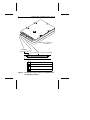
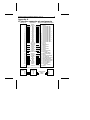
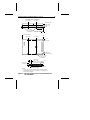
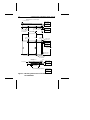
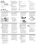
.......................... ST9235 Family: .......................... ST9080A .......................... ST9145A, ST9145AG .......................... ST9235A, ST9235AG .......................... Installation Guide .......................... Contents Read before you begin... . . . . . . . . . . . . . . 1 Installation overview . . . . . . . . . . . . . . . . . . . . 2 Setting master/slave jumpers . . . . . . . . . . . . . . .3 Connecting cables . . . . . . . . . . . . . . . . . . . . .3 Mounting the drive . . . . . . . . . . . . . . . . . . . . .5 Configuring system BIOS . . . . . . . . . . . . . . . . . . 5 Formatting and partitioning the drive . . . . . . . . . . . 8 Installation troubleshooting . . . . . . . . . . . . . . . . 9 Appendix A. AT interface connector pin assignments . 11 Appendix B. Mounting dimension drawings . . . . . . . 12 Appendix C. Technical support services . . . . . . . . 15 © 1993 Seagate Technology, Inc. All rights reserved Publication Number: 36216-001, Rev. B Seagate®, Seagate Technology®, and the Seagate logo are registered trademarks of Seagate Technology, Inc. SeaFAX, SeaFONE, SeaTDD, and SeaBOARD are trademarks of Seagate Technology, Inc. Other product names are trademarks or registered trademarks of their owners. Seagate reserves the right to change, without notice, product offerings or specifications. No part of this publication may be reproduced in any form without written permission of Seagate Technology, Inc. ST9235 Family Installation Guide, Rev. B 1 Read before you begin... Note. Drives in the ST9235 family are usually installed in notebook or laptop systems. Special training or tools may be needed to service these computers. In some instances, opening the case may void your warranty. Be sure to review the terms and conditions of your system warranty before opening the system enclosure. Warning. Always power off and unplug your computer system before touching any internal components. Observe static discharge precautions. • Keep the drive in its static-shielded bag until you are ready to complete the installation. • Do not touch the PC board or the I/O connector pins. • Always handle the drive by its edges or frame. Never apply pressure to the PC Board or to the drive’s top cover. • Use a grounded wrist strap. If none is available, ground yourself by touching the metal chassis of the system before handling any components. • Use antistatic padding on all work surfaces and avoid staticinducing carpeted areas. Inspection. When you are familiar with the handling precautions listed above, inspect the drive. If it appears to be damaged, contact your distributor or dealer immediately. Handle drives carefully. Improper handling during transit or shipping accounts for many installation problems. Even minor bumps can exert relatively large G forces on these drives. Always handle the drive carefully. In addition, do not attach any labels to the drive top cover, as they may prevent proper ventilation. 2 ST9235 Family Installation Guide, Rev. B Warranty. Contact your authorized Seagate distributor or dealer for warranty information. Maintenance and repair. Seagate drives do not require any preventive maintenance. The head/disc assembly is sealed and does not contain any user-serviceable components. Tampering with the factory seal voids the warranty. Seagate customer service centers are the only facilities authorized to service Seagate drives. Seagate does not sanction any third-party repair facilities. Shipping. When transporting or shipping a drive, you must use a Seagate-approved container. If possible, use an original Seagate shipping box with a Seagate Approved Package label. Shipping a drive in a nonapproved container voids the drive warranty. Seagate service centers may refuse receipt of components improperly packaged or obviously damaged in transit. Call your authorized Seagate distributor to purchase additional boxes. Seagate recommends shipping by an air-ride carrier experienced in handling computer equipment. Installation overview Drive installation can be divided into several logical steps: 1. 2. 3. 4. 5. Setting master/slave jumpers Connecting cables Mounting the drive Configuring the system BIOS Formatting and partitioning the drive Each of these steps is described in detail on the following pages. Some may not be applicable to your particular installation requirements. ST9235 Family Installation Guide, Rev. B 3 Setting master/slave jumpers Two drives may be controlled through a single drive controller cable with two connectors. In this case, one drive is designated as the master and the other is designated as the slave. As shown in Figure 1 on page 4, the jumpers on each drive must be set to identify which drive is master and which is slave. Connecting cables The ST9235 Family drives use a 44-pin AT interface connector cable with two rows of 22 female contacts on 0.079 inch (2 mm) centers (see Figure 1). Pin assignments for the AT interface are listed in Appendix A. Most cables have a stripe down one side, which designates pin 1. Make sure pin 1 on the interface cable connector is aligned to pin 1 on the drive interface connector and pin 1 on the host connector. To assist in cable alignment, pin 20 has been removed on the male interface connector on the drive. This type of connector is designed to be used with a keyed cable connector having a plug in place of pin 20. Before mounting the drive, be sure that the connecting cable is long enough to reach the drive, but not so long that it will be pinched when the system enclosure is replaced. Connecting cables for the ST9235 family drives must not be longer than 18 inches (457 mm). Power connections Power for the ST9235 family drives is supplied through the 44-pin interface connector (see Appendix A for specific pin assignments). Caution. These drives can accept only +5 volts DC power. Do not use +12 volts DC power. 4 ST9235 Family Installation Guide, Rev. B Note. Drive is shown with circuit board up. Master/slave Pin 1 configuration jumpers Pin 20 removed for keying Circuit board A B C D Drive is master; no slave present Drive is master; Seagate slave drive present Drive is slave; Seagate master drive present Reserved positions (do not use) Figure 1. AT interface cable connector and master/slave configuration jumpers ST9235 Family Installation Guide, Rev. B 5 Mounting the drive You can mount (and operate) a ST9235 family drive in any orientation. However, you must securely attach the drive to a rigid frame using four side-mounting screws or four bottom-mounting screws. Caution: To avoid damaging the drive: • Use M3X0.5 metric mounting screws only. • Do not insert mounting screws more than 0.150 inches (3.81 mm) into the mounting holes (except: 0.190 inches (4.82 mm) for the bottom-mounting holes of the ST9235A and ST9235AG). • Do not overtighten the screws (maximum torque: 3 inch-lb). Allow a minimum clearance of 0.030 inches (0.762 mm) around the entire perimeter of the drive for cooling airflow. Mounting dimension drawings for the ST9235 family drives are provided in Appendix B. As shown in these drawings, some ST9235 family drives conform to the industry standard MCC mounting specification. Refer to the ST9235 Family Product Manual (Seagate publication 36206-001) for further details. Configuring system BIOS Before the host system can recognize a new drive, you must enter basic information about the drive into the host system BIOS. Specifically, you need to know the number of cylinders, heads, and sectors, as well as the overall capacity of the drive you are installing. The table on page 6 lists these specifications for the ST9235 family drives. It is not necessary to understand these terms to set up the system BIOS. Read your system documentation or run your system setup program (described on the following page) to determine which 6 ST9235 Family Installation Guide, Rev. B drive types your BIOS supports. Another method is to run the FINDTYPE.EXE utility program, available from Seagate Technical Support services (on the SeaBOARD BBS) as described in Appendix C. The methods used to configure system BIOS vary from system to system. In many cases you can run a setup program from the DOS prompt. In other cases, you must initiate BIOS setup by pressing certain keys while the system is booting up. Within the setup program, there are three possible ways that you can specify your drive type: • Match your drive specifications (from the table below) with those of a drive type specified in the setup program. • Specify a custom or user-defined drive type in the setup program, then manually enter your drive specifications from the table below. • Select specifications lower than those required for your drive, and allow your drive to mimic the drive type selected. Drive Specification ST9080A ST9145A & ST9235A & ST9145AG ST9235AG No. cylinders No. read/write heads No. sectors per track Total No. sectors Capacity (Mbytes) BIOS calculated Usable 823 4 38 125,096 980 15 17 249,900 985 13 32 409,760 61.0 64.0 122.0 127.9 200.0 209.7 When the drive specifications are entered manually as a userdefined or custom drive type, the BIOS should display a drive capacity equal to that listed as BIOS calculated capacity in the ST9235 Family Installation Guide, Rev. B 7 table above. This value will be lower than the usable drive capacity. In a few situations, none of the drive types specified in your BIOS setup program will match your drive, and the setup program will not provide an opportunity to specify a custom drive type. In this case, consider the third option described above — allowing your ST9235 family drive to mimic one of the BIOS-supported drive types. During the BIOS setup process, simply select a drive type with a capacity that is less than or equal to the drive’s BIOS calculated capacity listed in the table on page 6. This drive type should have no more than 16 read/write heads or 63 sectors per track. In addition, the total number of sectors for that drive type (listed in the setup program) should not exceed the number of cylinders times the number of read/write heads times the number of sectors per track. In other words: Total sectors per drive ≤ (No. cylinders) × (No. read/write heads) × (No. sectors per track) BIOS compatibility recommendations The ST9235 family drives are AT interface compatible drives, which conform to ATA specifications. The host system BIOS must provide support for the AT interface command set. Consult the system documentation for information on the AT interface within your system. Several key compatibility issues are discussed below. In accordance with ATA specifications, the BIOS must reset any emulation/translation parameters after a hard reset is received from the host. In some configurations, the ST9235 family AT interface drives supply 11 bytes of Error Correction Code (ECC) with the Read Long and Write Long commands. Depending on the drive type, 8 ST9235 Family Installation Guide, Rev. B your system BIOS may look for 4 bytes of ECC. If your system BIOS expects 4 bytes of ECC and the drive supplies a different number of bytes, some drive diagnostic programs may fail, typically resulting in time-out errors. Consult your system documentation or call your system dealer or manufacturer for information on configuring your system to receive 11 bytes of ECC. Formatting and partitioning the drive Caution. Formatting or partitioning a drive that contains data may result in a partial or complete loss of that data. Make sure all data has been safely backed up before repartitioning or reformatting a drive. Seagate Technology assumes no liability for lost data. Low-level formatting Seagate AT Interface drives are low-level formatted at the factory and do not require additional low-level formatting prior to use. Partitioning A single disc drive can be subdivided into partitions that behave as separate drives (labeled C, D, E, etc.). Versions of DOS prior to Version 4.0 are not able to access more than 32 Mbytes of disc space as a single drive. Therefore, drives having a capacity of over 32 Mbytes must be divided into several smaller partitions for use with these older versions of DOS. Seagate does not recommend using ST9235 family drives with DOS versions prior to Version 3.3. To partition a drive, you must first boot the system using a floppy disk that contains system files. Partition the drive using the DOS FDISK utility program (described in your DOS manual). If you are partitioning a drive that will be used to boot the system, make sure that the primary DOS partition is marked active. ST9235 Family Installation Guide, Rev. B 9 High-level formatting Once the drive is partitioned, use the DOS FORMAT command (or equivalent utility program) to high-level format each of the drive partitions. This process verifies the information written by the low-level format and creates file allocation tables (used to catalog and access files). Consult your DOS manual for FORMAT command options. During formatting, DOS system files should be transferred to one disc partition (generally the “C” drive), so that the system can boot off of that drive. After high-level formatting a drive, you can verify the usable drive capacity using the DOS CHKDSK utility program. Installation troubleshooting Before calling Seagate Technical Support, please read and consider all the possibilities discussed below. The suggestions presented here will resolve the vast majority of installation problems. Warning. To avoid personal injury and damage to electronic components, always turn off and unplug the computer system before changing jumpers or touching any internal components. • Verify compatibility. Check the documentation for the host adapter and the drive to confirm that these components are appropriately matched for each other and to your system. • Verify your configuration. Refer to the drive and controller installation guides to make sure all jumper settings suit your configuration requirements. • Check all cables. Make sure all cables are securely connected. Ribbon cables are especially fragile. Make sure they are not crimped or damaged in any way. Having extra cables on hand for troubleshooting saves time and frustration. Most cables have a stripe down one side to designate the pin 1 10 ST9235 Family Installation Guide, Rev. B location. Make sure pin 1 on the interface cable connector is connected to pin 1 on the drive interface connector and pin 1 on the host connector. Refer to Figure 1 on page 4 for the location of pin 1 on the drive interface connector. • Check all cards. Make sure all cards are secured in the expansion slots on the motherboard. Full size (16-bit) cards cannot be plugged into half-size (8-bit) slots. Make sure all cards are plugged into appropriately sized expansion slots. Once the cards are permanently installed and the system is running properly, use mounting screws to secure the cards in place. • Check the power supply specifications. The output of your power supply may not be sufficient to meet the power requirements of the new devices you have installed. If you are not sure whether the power supply meets the system requirements, consult your system dealer or distributor. • Use the same version of DOS throughout your system. The same version of DOS must be used throughout all phases of building and configuring your system. • Verify the BIOS drive type. The BIOS drive type you specified during system setup must approximate, but not exceed, the specifications and maximum drive capacity of the disc drive. Refer to the BIOS configuration section of this manual to double check your drive specifications against those specified in your system BIOS. • Check for viruses. Before installing any new software, scan the installation diskettes for viruses. After the software has been installed on the hard disc, scan that drive for viruses. Symptoms of viruses can include intermittent system lockups, reboots and drive errors. ST9235 Family Installation Guide, Rev. B 11 Appendix A. AT interface connector pin assignments Drive pin # Signal name Host pin # and signal description 1 2 3 4 5 6 7 8 9 10 11 12 13 14 15 16 17 18 19 20 21 22 23 24 25 26 27 *28 Reset– Ground DD7 DD8 DD6 DD9 DD5 DD10 DD4 DD11 DD3 DD12 DD2 DD13 DD1 DD14 DD0 DD15 Ground (removed) DMARQ Ground DIOW– Ground DIOR– Ground IORDY SPSYNC:CSEL 1 2 3 4 5 6 7 8 9 10 11 12 13 14 15 16 17 18 19 20 21 22 23 24 25 26 27 28 29 30 31 32 33 *34 35 36 37 38 *39 DMACK– Ground INTRQ IOCS16– DA1 PDIAG– DA0 DA2 CS1FX– CS3FX– DASP– 29 30 31 32 33 34 35 36 37 38 39 40 Ground 40 Host Reset Ground Host Data Bus Bit 7 Host Data Bus Bit 8 Host Data Bus Bit 6 Host Data Bus Bit 9 Host Data Bus Bit 5 Host Data Bus Bit 10 Host Data Bus Bit 4 Host Data Bus Bit 11 Host Data Bus Bit 3 Host Data Bus Bit 12 Host Data Bus Bit 2 Host Data Bus Bit 13 Host Data Bus Bit 1 Host Data Bus Bit 14 Host Data Bus Bit 0 Host Data Bus Bit 15 Ground (No Pin) DMA Request Ground Host I/O Write Ground Host I/O Read Ground I/O Channel Ready Spindle sync or Cable Select DMA Acknowledge Ground Host Interrupt Request Host 16 Bit I/O Host Address Bus Bit 1 Passed Diagnostics Host Address Bus Bit 0 Host Address Bus Bit 2 Host Chip Select 0 Host Chip Select 1 Drive Active/ Drive 1 Present Ground *Indicates master-slave signals (details shown below). Drive 1 (slave) 28 34 39 Drive 0 (master) 28 34 39 Host SPSYNC:CSEL PDIAG– DASP– 28 34 39 12 ST9235 Family Installation Guide, Rev. B Appendix B. Mounting dimension drawings Dimensions are in inches (mm) 0.492 ± 0.005 (12.50 ± 0.13) 0.066 ± 0.020 (1.68 ± 0.51) 0.000 0.100 ± 0.010 (2.54 ± 0.25) 0.146 +0.011, –0.008 (3.71 +0.28, –0.20) 4X 3 mm × 0.5 mm 0.15 in (3.81 mm) min. full thread 1.227 ± 0.025 (31.17 ± 0.64) 4.010 (101.85) max 1.500 ± 0.010 (38.10 ± 0.25) 0.000 1.375 ± 0.015 (34.93 ± 0.38) 0.155 ± 0.025 (3.94 ± 0.64) 0.000 0.275 ± 0.025 (6.99 ± 0.64) 2.760 (70.10) max 2.430 ± 0.020 (61.72 ± 0.51) 4X 3 mm × 0.5 mm 0.15 in (3.81 mm) min. full thread Pin 20 removed for keying Pin 1 0.166 ± 0.015 (4.22 ± 0.38) 0.079 (2.00) 0.079 (2.00) 1.654 (42.00) Figure 2. Mounting dimensions for the ST9080A ST9235 Family Installation Guide, Rev. B 13 Dimensions are in inches (mm) 2.875 (73.03) 1.375 (34.93) 0.750 max (19.05) 0.157 ± 0.020 (3.99 ± 0.51) 0.000 0.118 (3.00) 4X 3 mm × 0.5 mm, 0.15 in (3.81 mm) min full thread 1.227 ± 0.025 (31.17 ± 0.64) 0.146 +0.011, –0.008 (3.71 +0.28, –0.20) 4.010 max (101.85) 2.875 (73.03) 0.000 1.375 (34.93) 0.000 0.160 (4.06) 2.590 (65.79) 2.760 max (70.10) 4X 3 mm × 0.5 mm, 0.15 in (3.81 mm) min full thread 0.394 ± 0.025 (10.01 ± 0.64) Pin 1 0.079 (2.00) pin spacing 0.079 (2.00) pin spacing Pin 20 removed for keying Notes: 1. The ST9145A form-factor complies with MCC mounting standards. 2. All dimensional tolerances are ± 0.010 inch (± 0.25 mm) maximum unless otherwise specified. Figure 3. Mounting dimensions for the ST9145A and the ST9145AG 14 ST9235 Family Installation Guide, Rev. B Dimensions are in inches (mm) 0.750 (19.05) max 0.066 ± 0.020 (1.68 ± 0.51) 0.039 ± 0.020 (0.99 ± 0.51) 0.000 4X 3 mm × 0.5 mm 0.15 in. (3.81 mm) min. full thread 0.230 ± 0.010 (5.84 ± 0.25) 0.118 ± 0.010 (3.00 ± 0.25) 0.146 +0.011, –0.008 (3.71 +0.28, –0.20) 1.227 ± 0.025 (31.17 ± 0.64) 4.010 (101.85) max 1.500 ± 0.010 (38.10 ± 0.25) 0.000 1.375 ± 0.015 (34.93 ± 0.38) 0.155 ± 0.025 (3.94 ± 0.64) 0.000 0.275 ± 0.025 (6.99 ± 0.64) 0.239 ± 0.025 (6.07 ± 0.64) 2.760 (70.10) max 2.430 ± 0.020 (61.72 ± 0.51) 4X 3 mm × 0.5 mm 0.15 in (3.81 mm) min. full thread Pin 20 removed for keying Pin 1 0.166 ± 0.015 (4.22 ± 0.38) 0.157 ± 0.009 (3.99 ± 0.23) 0.079 (2.00) 0.079 (2.00) 1.654 (42.00) Key to mounting specifications: non-MCC mount MCC mount Figure 4. Mounting dimensions for the ST9235A and the ST9235AG ST9235 Family Installation Guide, Rev. B 15 Appendix C. Technical support services Product technical support is available for all Seagate products by calling the SeaFAX, SeaFONE, SeaTDD and SeaBOARD services described below. These services are free, but long-distance charges (if any) are paid by the user. SeaFAX. 408/438-2620 You can use a touch-tone telephone to access Seagate’s automated FAX system and select technical support information by return FAX. This service is available 24 hours a day, 7 days a week. SeaFONE. 408/438-8222 Seagate’s phone system provides recorded technical information on selected Seagate products while you are on hold. Technical support specialists are available to answer questions from 8:00 A.M. to 5:00 P.M. (PST), Monday through Friday. Recordings are accessible 24 hours a day, 7 days a week. SeaTDD. 408/438-5382 Using a TDD (Telecommunications Device for the Deaf) device, you can send questions or comments 24 hours a day, or communicate with a technical support specialist between 8:00 A.M. and 5:00 P.M. (PST), Monday through Friday. SeaBOARD. The Seagate Technical Support Bulletin Board System (BBS) is available 24 hours a day, 7 days a week. A modem is required to access this service. Set your communications software for eight data bits, no parity and one stop bit (8N1). Using the SeaBOARD BBS you can obtain: • Specifications and configuration for Seagate products. • Reprints of Seagate documentation. 16 ST9235 Family Installation Guide, Rev. B • A directory of information and helpful utility programs that you can download to your own computer. • The FINDTYPE.EXE utility program, which can be very useful in drive installation. It compares the drive’s geometry with all geometries supported by your system BIOS. This program either signals that an exact match exists between the drive geometry and the system BIOS, or recommends the closest drive type supported by your system BIOS. BBS location Modem number Maximum baud rate United States 408-438-8771 9600 England 44-62-847-8011 9600 France 33-1-40 67 10 34 9600 Germany 49-89-140-9331 2400 Singapore 65-292-6973 9600 Australia 61-2-756-2359 9600 Seagate Technology, Inc. 920 Disc Drive, Scotts Valley, CA 95066, USA Publication Number: 36216-001, Rev. B, Printed in USA